EP3173610A1 - Intake pipe for an internal combustion engine provided with a thermoelectric conversion device and internal combustion engine provided with such a pipe - Google Patents
Intake pipe for an internal combustion engine provided with a thermoelectric conversion device and internal combustion engine provided with such a pipe Download PDFInfo
- Publication number
- EP3173610A1 EP3173610A1 EP16200824.7A EP16200824A EP3173610A1 EP 3173610 A1 EP3173610 A1 EP 3173610A1 EP 16200824 A EP16200824 A EP 16200824A EP 3173610 A1 EP3173610 A1 EP 3173610A1
- Authority
- EP
- European Patent Office
- Prior art keywords
- supercharger
- pipe
- internal combustion
- segment
- combustion engine
- Prior art date
- Legal status (The legal status is an assumption and is not a legal conclusion. Google has not performed a legal analysis and makes no representation as to the accuracy of the status listed.)
- Granted
Links
Images

Classifications
-
- F—MECHANICAL ENGINEERING; LIGHTING; HEATING; WEAPONS; BLASTING
- F02—COMBUSTION ENGINES; HOT-GAS OR COMBUSTION-PRODUCT ENGINE PLANTS
- F02M—SUPPLYING COMBUSTION ENGINES IN GENERAL WITH COMBUSTIBLE MIXTURES OR CONSTITUENTS THEREOF
- F02M35/00—Combustion-air cleaners, air intakes, intake silencers, or induction systems specially adapted for, or arranged on, internal-combustion engines
- F02M35/10—Air intakes; Induction systems
- F02M35/10242—Devices or means connected to or integrated into air intakes; Air intakes combined with other engine or vehicle parts
- F02M35/10268—Heating, cooling or thermal insulating means
-
- F—MECHANICAL ENGINEERING; LIGHTING; HEATING; WEAPONS; BLASTING
- F02—COMBUSTION ENGINES; HOT-GAS OR COMBUSTION-PRODUCT ENGINE PLANTS
- F02B—INTERNAL-COMBUSTION PISTON ENGINES; COMBUSTION ENGINES IN GENERAL
- F02B29/00—Engines characterised by provision for charging or scavenging not provided for in groups F02B25/00, F02B27/00 or F02B33/00 - F02B39/00; Details thereof
- F02B29/04—Cooling of air intake supply
-
- F—MECHANICAL ENGINEERING; LIGHTING; HEATING; WEAPONS; BLASTING
- F02—COMBUSTION ENGINES; HOT-GAS OR COMBUSTION-PRODUCT ENGINE PLANTS
- F02M—SUPPLYING COMBUSTION ENGINES IN GENERAL WITH COMBUSTIBLE MIXTURES OR CONSTITUENTS THEREOF
- F02M31/00—Apparatus for thermally treating combustion-air, fuel, or fuel-air mixture
- F02M31/20—Apparatus for thermally treating combustion-air, fuel, or fuel-air mixture for cooling
-
- Y—GENERAL TAGGING OF NEW TECHNOLOGICAL DEVELOPMENTS; GENERAL TAGGING OF CROSS-SECTIONAL TECHNOLOGIES SPANNING OVER SEVERAL SECTIONS OF THE IPC; TECHNICAL SUBJECTS COVERED BY FORMER USPC CROSS-REFERENCE ART COLLECTIONS [XRACs] AND DIGESTS
- Y02—TECHNOLOGIES OR APPLICATIONS FOR MITIGATION OR ADAPTATION AGAINST CLIMATE CHANGE
- Y02T—CLIMATE CHANGE MITIGATION TECHNOLOGIES RELATED TO TRANSPORTATION
- Y02T10/00—Road transport of goods or passengers
- Y02T10/10—Internal combustion engine [ICE] based vehicles
- Y02T10/12—Improving ICE efficiencies
Definitions
- the present invention relates to an intake pipe for an internal combustion engine provided with a thermoelectric conversion device.
- the present invention also relates to an internal combustion engine provided with an intake pipe comprising a thermoelectric conversion device.
- an internal combustion engine supercharged by means of a turbocharger supercharging system comprises a head defining a plurality of cylinders, each of which is connected to an intake manifold via at least one respective intake valve and to an exhaust manifold via at least one respective exhaust valve, and inside which the fuel is injected by an injector.
- thermoelectric conversion devices in the engine compartment, which allow to recover the electric energy required for the charging process of the battery of the vehicle, while eliminating the alternator, which is a rather expensive and bulky component.
- the documents WO-A1-2012067565 , US-A1-2003234008 , US-B1-6817197 , US-A1-2006122762 and JP-A-2007255364 describe internal combustion engines provided with respective thermoelectric conversion devices, which, however, are characterized by reduced efficiency.
- Object of the present invention is to provide an intake pipe for an internal combustion engine provided with a thermoelectric conversion device, said pipe allows to overcome the drawbacks of the state of the art and is, at the same time, easy to manufacture.
- a further object of the present invention is to provide an internal combustion engine provided with an intake pipe comprising a thermoelectric conversion device, which allows to overcome the drawbacks of the state of the art and is, at the same time, easy to manufacture.
- thermoelectric conversion device a component for an internal combustion engine provided with a thermoelectric conversion device and an internal combustion engine provided with an intake pipe comprising a thermoelectric conversion device are provided, as claimed in the appended claims.
- numeral 1 indicates, as a whole, an internal combustion engine supercharged by means of a turbocharger supercharging system 2.
- the internal combustion engine 1 comprises a number of cylinders 3 (in particular, Figure 1 shows four cylinders 3), each of which is connected to an intake manifold 4 via at least one respective intake valve (not shown) and to an exhaust manifold 5 via at least one respective exhaust valve (not shown).
- the intake manifold 4 receives fresh air (i.e. air from the external environment) through an intake pipe 6, which is provided with an air filter 7 and is controlled by a throttle valve 8.
- An intercooler 9, whose function is to cool the intake air, is arranged along the intake pipe 6.
- the exhaust manifold 5 is connected to an exhaust pipe 10 that feeds the exhaust gases produced by combustion to an exhaust system, which emits the gases produced by combustion into the atmosphere and normally comprises at least one catalyst 11 and at least one silencer (not shown) arranged downstream of the catalyst 11.
- the supercharging system 2 of the internal combustion engine 1 comprises a turbocharger 12 provided with a turbine 13, which is arranged along the exhaust pipe 10 so as to rotate at high speed under the action of the exhaust gases expelled from the cylinders 3, and a supercharger 14, which is arranged along the intake pipe 6 and is mechanically connected to the turbine 13 to be driven into rotation by the turbine 13 itself, so as to increase the pressure of the air fed into the feeding pipe 6.
- the exhaust pipe 10 is provided with a bypass pipe 15, which is connected in parallel to the turbine 13 so as to have its ends connected upstream and downstream of the turbine 13 itself; a wastegate valve 16 is arranged along the bypass pipe 15, the former being adapted to adjust the flow rate of the exhaust gases flowing through the bypass pipe 15 and controlled by an actuator 17.
- the internal combustion engine 1 also comprises a high-pressure EGR HP circuit which in turn comprises a bypass pipe 18 connected in parallel to the assembly formed by the cylinders 3, the intake manifold 4 and the exhaust manifold 5.
- a Poff valve 19 is arranged along the bypass pipe 18, the former being adapted to adjust the flow rate of the exhaust gases flowing through the bypass pipe 18 and controlled by an EGR solenoid valve 20.
- a heat exchanger 21, whose function is to cool the gases exiting the exhaust manifold 5, is arranged along the bypass pipe 18, downstream of the Poff valve 19.
- the internal combustion engine 1 is controlled by an electronic control unit 22, which supervises the operation of all the components of the internal combustion engine 1.
- the electronic control unit 22 is connected to a sensor 23, which measures the temperature and the pressure of the gas mixture in the intake manifold 4, to a sensor 24, which measures the rotational speed of the internal combustion engine 1, and to a sensor 25 (typically, a UHEGO or UEGO oxygen linear sensor - of a known type and not described in detail), which measures the air/fuel ratio of the exhaust gases upstream of the catalyst 11.
- the internal combustion engine 1 lastly comprises a low-pressure EGR LP circuit, which in turn comprises a bypass pipe 26 provided along the exhaust pipe 10; the bypass pipe 26 is connected in parallel to the turbocharger 12.
- An EGR valve 27 is arranged along the bypass pipe 26, the former being adapted to adjust the flow rate of the exhaust gases flowing through the bypass pipe 26.
- a heat exchanger 28, whose function is to cool the gases exiting the exhaust manifold 5 and entering the supercharger 14, is also arranged along the bypass pipe 26, upstream of the valve 27.
- the low-pressure EGR LP circuit comprises a three-way mixing device which is arranged at the intersection between the exhaust pipe 10 and the intake pipe 6, whose function is to adjust the mixing of the exhaust gases coming from the exhaust pipe 10 with the fresh air present in the intake pipe 6.
- the low-pressure EGR LP circuit originates from the exhaust pipe 10 downstream of the catalyst 11 so as to collect the exhaust gases, which have already been treated by the catalyst 11 itself and have a pressure only slightly higher than the atmospheric pressure; in this way, the recirculated exhaust gases from the bypass pipe 26 are "cleaner", i.e. they have a smaller amount of pollutants.
- This configuration is also referred to as “Long-Route" EGR, since the bypass pipe 26 must be longer than normal to get downstream of the catalyst 11.
- the electronically controlled throttle valve 8 comprises a valve body 29 housing an electric engine 30, a tubular feeding pipe 31 having a circular cross section through which the air sucked in from the internal combustion engine flows, and a throttle plate (not shown), which is circular in shape, engages the feeding pipe 31 and rotates between an open position and a closed position of the feeding pipe 31 due to the action of an actuator device.
- the electric engine 30 has a cylindrical body, which is arranged in a tubular housing 32 of the valve body 29 arranged next to the feeding pipe 31.
- the valve body 29 consists entirely of a first material, internally defining the feeding pipe 31, and comprises, among other things, the tubular housing 32 which is arranged next to the feeding pipe 31 and houses the electric engine 30.
- the material that constitutes the valve body 29 is a metal material, in particular aluminium.
- the valve body 29 comprises a conditioning circuit 33 as described, for example, in patent applications EP2921687 and BO2014A000349 , which are entirely incorporated herein by reference.
- the conditioning circuit 33 in turn comprises a channel 34 and a pipe 35.
- the channel 34 is substantially L-shaped and surrounds the feeding pipe 31 on two sides.
- the inside of the channel 34 houses the pipe 35, which is also substantially L-shaped and is made of steel, preferably a stainless steel.
- the pipe 35 is in hydraulic communication with a pump (not shown), which circulates the conditioning fluid and supplies it to the pipe 35 for the conditioning of the different parts of the throttle valve 8. It clearly appears that the conditioning circuit 33 may alternatively have a different shape from the substantially L shape described above.
- the throttle valve 8 comprises a thermoelectric conversion device 36.
- the thermoelectric conversion device 36 comprises a plurality of Peltier coolers 37.
- the operation of the Peltier coolers 37 provides for exploiting a thermoelectric effect whereby, in a circuit comprising metal conductors, electricity is generated due to a temperature difference ⁇ T.
- a current will flow which is proportional to the temperature difference ⁇ T between the hot side and the cold side.
- the Peltier coolers 37 can then be used as a generator of electrical energy.
- Each Peltier cooler 37 comprises a very thin plate provided with a surface that faces the hot side and a surface that faces the cold side.
- the plate is formed by two semiconductor materials mutually connected by a layer of electrically conductive material, preferably copper.
- the plate has, in plan view, a preferably square shape. According to a preferred embodiment, the surface that faces the hot side can withstand temperatures up to approximately 200°C, whereas the surface that faces the cold side is at temperatures between 30°C and 90°C.
- the plate is of the insulated type and namely has a lower cladding layer and an upper cladding layer, made of an electrically insulating material, preferably ceramic, capable of optimising the efficiency of the Peltier cooler.
- each Peltier cooler 37 The potential difference at the terminals of each Peltier cooler 37 is obtained thanks to the temperature gradient ⁇ T, because the two metals generate different electric potentials at the two sides having different temperatures, giving rise to a current flow which produces a magnetic field.
- the efficiency of the Peltier coolers 37 is at a maximum when the difference between the hot side and the cold side is very high.
- the Peltier coolers 37 are housed in respective seats made in the valve body 29, and comprise a hot side, which is thermally coupled to a surface delimiting the hot zone from which to extract heat in the area of the feeding pipe 31, and a cold side, which is thermally coupled to a surface in the area of the conditioning circuit 33. Therefore, the Peltier coolers 37 can be taken as generators of electrical energy to assist in the charging process of a battery of the vehicle.
- FIG. 3 illustrates a module 38 which incorporates on the inside the intake manifold 4 and the intercooler 9.
- the module 38 comprises a central body 39 made of any thermoplastic material capable of withstanding temperatures in the range of 210 - 215°C.
- the central body 39 has a substantially parallelepiped shape and internally defines the intake manifold 4 for collecting the air coming from the supercharger 14 to be fed to the four cylinders 3.
- the central body 39 comprises an inlet opening 40 for the intake of fresh air, which communicates with the intake pipe 6, so as to inject the fresh air coming from the supercharger 14 into the central body 39.
- the intercooler 9, whose function is to cool the fresh air sucked from the supercharger 14, is defined inside the central body 39.
- the intercooler 9 substantially consists of an air/water heat exchanger, wherein the air sucked from the intake pipe 6 (i.e., coming from the supercharger 14) enters at a temperature of about 200°C.
- the fresh air sucked from the intake pipe 6 is cooled to approximately 50°C and leaves the central body 39 through four pipes 41, each of which is associated with a respective cylinder 3 and along which their respective intake valves (not shown) are arranged.
- the pipes 41 are formed at a major side wall of the central body 39 opposite to the major side wall in which the inlet opening 40 is formed.
- the central body 31 is then provided with a cooling hydraulic circuit 42 supplied with a cooling fluid, which enters the central body 39 through an inlet pipe 43, is fed into said central body 39, and exits through an outlet pipe 44; both the inlet pipe 43 and the outlet pipe 44 are formed at an upper wall of the central body 39.
- the module 38 also comprises a thermoelectric conversion device 45.
- the thermoelectric conversion device 45 comprises a plurality of Peltier coolers 46, whose operation is entirely similar to that described in the foregoing discussion on the Peltier coolers 37.
- the Peltier coolers 46 comprise a hot side that is hit by the flow of air sucked from the intake pipe 6, which defines the hot zone from which to extract heat, and a cold side, which is thermally coupled to a surface in the area of the cooling hydraulic circuit 42.
- the Peltier coolers 46 are housed in the central body 39 with an orientation parallel to a minor side wall of the central body 39 itself. In this case too, therefore, the Peltier coolers 37 can be taken as generators of electrical energy to assist in the charging process of a battery of the vehicle.
- the central body 39 is also provided with an electrical connector 39' in order to achieve the electrical connection of the thermoelectric conversion device 45.
- Figures 3 and 4 show a segment 47 of the intake pipe 6, which connects the supercharger 14 to the throttle valve 8 with cylindrical symmetry around an axis X.
- the segment 47 is provided with an outer jacket 48 coaxial with the axis X and defined by a tubular body having, in its cross section, a polygonal (in particular, hexagonal) shape inside which a conditioning circuit 49 is defined.
- the conditioning circuit 49 is supplied with a cooling fluid, which enters the jacket 48 through an inlet pipe 50, flows inside the jacket 48 (in particular, inside a chamber defined between a lower wall 48* and an upper wall 48** of the jacket 48), and exits through an outlet pipe 51.
- the segment 47 is provided with an inner jacket 52 coaxial with the axis X, interposed between the outer jacket 48 and the segment 47, is defined by a tubular body having, in its cross section, a polygonal (in particular, hexagonal) shape complementary to the shape of the outer jacket 48.
- the inner jacket 52 also comprises a thermoelectric conversion device 53.
- the thermoelectric conversion device 53 comprises a plurality of Peltier coolers 54, whose operation is entirely similar to that described in the foregoing discussion on the Peltier coolers 37.
- Each Peltier cooler 54 comprises a very thin plate provided with a surface that faces the hot side and a surface that faces the cold side, and arranged next to one another, so as to define the polygonal profile of the inner jacket 52.
- the Peltier coolers 54 comprise a hot side, which is thermally coupled to a surface delimiting the hot zone from which to extract heat in the area of the segment 47, and a cold side, which is thermally coupled to a surface in the area of the outer jacket 48. Therefore, the Peltier coolers 37 can be taken as generators of electrical energy to assist in the charging process of a battery of the vehicle.
- the outer jacket 48 is also provided with an electrical connector 48' in order to achieve the electrical connection of the thermoelectric conversion device 53.
- thermoelectric conversion devices 36, 45, 53 may find advantageous application in any component or combination of components of the circuit portion that allows to exploit the temperature differences between the heat of the air flow exiting the supercharger 14 (approximately 200°C) and the cooling fluid of the internal combustion engine 1 or other circuit conditioning fluids (30°C - 90°C).
- the thermoelectric conversion devices 36, 45, 53 may find advantageous application also in the absence of said conditioning circuits.
- thermoelectric conversion devices 36, 45, 53 described in the foregoing discussion, which can be used individually or in combination in the supercharged internal combustion engine 1.
- thermoelectric conversion devices 36, 45, 53 to the throttle valve 8
- intake manifold 4 and segment 47 of the intake pipe 6 allows to recover the electric energy required for the charging process of the battery of the vehicle, while eliminating the alternator, which is a rather expensive and bulky component.
Landscapes
- Engineering & Computer Science (AREA)
- Chemical & Material Sciences (AREA)
- Combustion & Propulsion (AREA)
- Mechanical Engineering (AREA)
- General Engineering & Computer Science (AREA)
- Supercharger (AREA)
- Pharmaceuticals Containing Other Organic And Inorganic Compounds (AREA)
Abstract
Description
- The present invention relates to an intake pipe for an internal combustion engine provided with a thermoelectric conversion device.
- The present invention also relates to an internal combustion engine provided with an intake pipe comprising a thermoelectric conversion device.
- As is known, an internal combustion engine supercharged by means of a turbocharger supercharging system comprises a head defining a plurality of cylinders, each of which is connected to an intake manifold via at least one respective intake valve and to an exhaust manifold via at least one respective exhaust valve, and inside which the fuel is injected by an injector.
- Each cylinder houses a respective piston mechanically connected via a connecting rod to a crankshaft so as to transmit to said crankshaft the force generated by the combustion inside the cylinder. Typically, the crankshaft also drives into rotation an alternator designed for converting the mechanical energy generated by the internal combustion engine into electrical energy required for the charging process of a battery of the vehicle. However, the alternator is a rather expensive, bulky and heavy component to drive into rotation, with negative effects on the overall performance of the internal combustion engine.
- To solve this problem, it has been proposed to insert thermoelectric conversion devices in the engine compartment, which allow to recover the electric energy required for the charging process of the battery of the vehicle, while eliminating the alternator, which is a rather expensive and bulky component. The documents
WO-A1-2012067565 ,US-A1-2003234008 ,US-B1-6817197 ,US-A1-2006122762 andJP-A-2007255364 - Object of the present invention is to provide an intake pipe for an internal combustion engine provided with a thermoelectric conversion device, said pipe allows to overcome the drawbacks of the state of the art and is, at the same time, easy to manufacture.
- A further object of the present invention is to provide an internal combustion engine provided with an intake pipe comprising a thermoelectric conversion device, which allows to overcome the drawbacks of the state of the art and is, at the same time, easy to manufacture.
- According to the present invention, a component for an internal combustion engine provided with a thermoelectric conversion device and an internal combustion engine provided with an intake pipe comprising a thermoelectric conversion device are provided, as claimed in the appended claims.
- The present invention will now be described with reference to the accompanying drawings, which illustrate a non-limiting embodiment thereof, in which:
-
Figure 1 is a schematic view of a supercharged internal combustion engine according to the present invention; -
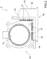
Figure 2 is a plan view of a throttle valve of the internal combustion engine ofFigure 1 ; -
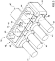
Figure 3 is a perspective view of an intake manifold of the internal combustion engine ofFigure 1 ; and -
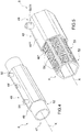
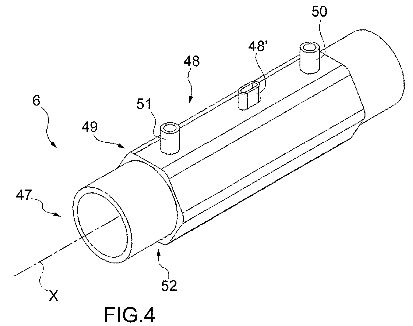
Figures 4 and 5 are perspective views of a segment of an intake pipe of the internal combustion engine ofFigure 1 according to the present invention. - In
Figure 1 , numeral 1 indicates, as a whole, an internal combustion engine supercharged by means of aturbocharger supercharging system 2. - The internal combustion engine 1 comprises a number of cylinders 3 (in particular,
Figure 1 shows four cylinders 3), each of which is connected to anintake manifold 4 via at least one respective intake valve (not shown) and to anexhaust manifold 5 via at least one respective exhaust valve (not shown). Theintake manifold 4 receives fresh air (i.e. air from the external environment) through anintake pipe 6, which is provided with anair filter 7 and is controlled by athrottle valve 8. Anintercooler 9, whose function is to cool the intake air, is arranged along theintake pipe 6. Theexhaust manifold 5 is connected to anexhaust pipe 10 that feeds the exhaust gases produced by combustion to an exhaust system, which emits the gases produced by combustion into the atmosphere and normally comprises at least onecatalyst 11 and at least one silencer (not shown) arranged downstream of thecatalyst 11. - The
supercharging system 2 of the internal combustion engine 1 comprises aturbocharger 12 provided with aturbine 13, which is arranged along theexhaust pipe 10 so as to rotate at high speed under the action of the exhaust gases expelled from thecylinders 3, and asupercharger 14, which is arranged along theintake pipe 6 and is mechanically connected to theturbine 13 to be driven into rotation by theturbine 13 itself, so as to increase the pressure of the air fed into thefeeding pipe 6. - The
exhaust pipe 10 is provided with abypass pipe 15, which is connected in parallel to theturbine 13 so as to have its ends connected upstream and downstream of theturbine 13 itself; awastegate valve 16 is arranged along thebypass pipe 15, the former being adapted to adjust the flow rate of the exhaust gases flowing through thebypass pipe 15 and controlled by an actuator 17. - The internal combustion engine 1 also comprises a high-pressure EGRHP circuit which in turn comprises a
bypass pipe 18 connected in parallel to the assembly formed by thecylinders 3, theintake manifold 4 and theexhaust manifold 5. APoff valve 19 is arranged along thebypass pipe 18, the former being adapted to adjust the flow rate of the exhaust gases flowing through thebypass pipe 18 and controlled by anEGR solenoid valve 20. Aheat exchanger 21, whose function is to cool the gases exiting theexhaust manifold 5, is arranged along thebypass pipe 18, downstream of thePoff valve 19. - The internal combustion engine 1 is controlled by an
electronic control unit 22, which supervises the operation of all the components of the internal combustion engine 1. Theelectronic control unit 22 is connected to asensor 23, which measures the temperature and the pressure of the gas mixture in theintake manifold 4, to asensor 24, which measures the rotational speed of the internal combustion engine 1, and to a sensor 25 (typically, a UHEGO or UEGO oxygen linear sensor - of a known type and not described in detail), which measures the air/fuel ratio of the exhaust gases upstream of thecatalyst 11. - The internal combustion engine 1 lastly comprises a low-pressure EGRLP circuit, which in turn comprises a
bypass pipe 26 provided along theexhaust pipe 10; thebypass pipe 26 is connected in parallel to theturbocharger 12. AnEGR valve 27 is arranged along thebypass pipe 26, the former being adapted to adjust the flow rate of the exhaust gases flowing through thebypass pipe 26. Aheat exchanger 28, whose function is to cool the gases exiting theexhaust manifold 5 and entering thesupercharger 14, is also arranged along thebypass pipe 26, upstream of thevalve 27. Alternatively, the low-pressure EGRLP circuit comprises a three-way mixing device which is arranged at the intersection between theexhaust pipe 10 and theintake pipe 6, whose function is to adjust the mixing of the exhaust gases coming from theexhaust pipe 10 with the fresh air present in theintake pipe 6. - The low-pressure EGRLP circuit originates from the
exhaust pipe 10 downstream of thecatalyst 11 so as to collect the exhaust gases, which have already been treated by thecatalyst 11 itself and have a pressure only slightly higher than the atmospheric pressure; in this way, the recirculated exhaust gases from thebypass pipe 26 are "cleaner", i.e. they have a smaller amount of pollutants. This configuration is also referred to as "Long-Route" EGR, since thebypass pipe 26 must be longer than normal to get downstream of thecatalyst 11. - As shown in
Figure 2 , the electronically controlledthrottle valve 8 comprises avalve body 29 housing anelectric engine 30, atubular feeding pipe 31 having a circular cross section through which the air sucked in from the internal combustion engine flows, and a throttle plate (not shown), which is circular in shape, engages thefeeding pipe 31 and rotates between an open position and a closed position of thefeeding pipe 31 due to the action of an actuator device. - The
electric engine 30 has a cylindrical body, which is arranged in atubular housing 32 of thevalve body 29 arranged next to thefeeding pipe 31. Thevalve body 29 consists entirely of a first material, internally defining thefeeding pipe 31, and comprises, among other things, thetubular housing 32 which is arranged next to thefeeding pipe 31 and houses theelectric engine 30. According to a preferred embodiment, the material that constitutes thevalve body 29 is a metal material, in particular aluminium. Lastly, thevalve body 29 comprises aconditioning circuit 33 as described, for example, in patent applicationsEP2921687 andBO2014A000349 conditioning circuit 33 in turn comprises achannel 34 and apipe 35. Thechannel 34 is substantially L-shaped and surrounds thefeeding pipe 31 on two sides. The inside of thechannel 34 houses thepipe 35, which is also substantially L-shaped and is made of steel, preferably a stainless steel. Thepipe 35 is in hydraulic communication with a pump (not shown), which circulates the conditioning fluid and supplies it to thepipe 35 for the conditioning of the different parts of thethrottle valve 8. It clearly appears that theconditioning circuit 33 may alternatively have a different shape from the substantially L shape described above. - Lastly, the
throttle valve 8 comprises athermoelectric conversion device 36. In particular, thethermoelectric conversion device 36 comprises a plurality of Peltiercoolers 37. As is known, the operation of the Peltiercoolers 37 provides for exploiting a thermoelectric effect whereby, in a circuit comprising metal conductors, electricity is generated due to a temperature difference ΔT. By heating one side of the reversible Peltier cooler 37 (the "hot side") and cooling the other side (the "cold side") in an electrical circuit connected to the terminals of the Peltiercoolers 37, a current will flow which is proportional to the temperature difference ΔT between the hot side and the cold side. The Peltiercoolers 37 can then be used as a generator of electrical energy. - Each Peltier
cooler 37 comprises a very thin plate provided with a surface that faces the hot side and a surface that faces the cold side. Typically, the plate is formed by two semiconductor materials mutually connected by a layer of electrically conductive material, preferably copper. The plate has, in plan view, a preferably square shape. According to a preferred embodiment, the surface that faces the hot side can withstand temperatures up to approximately 200°C, whereas the surface that faces the cold side is at temperatures between 30°C and 90°C. - According to a preferred embodiment, the plate is of the insulated type and namely has a lower cladding layer and an upper cladding layer, made of an electrically insulating material, preferably ceramic, capable of optimising the efficiency of the Peltier cooler.
- The potential difference at the terminals of each Peltier
cooler 37 is obtained thanks to the temperature gradient ΔT, because the two metals generate different electric potentials at the two sides having different temperatures, giving rise to a current flow which produces a magnetic field. - Clearly, the efficiency of the Peltier
coolers 37 is at a maximum when the difference between the hot side and the cold side is very high. For this reason, the Peltiercoolers 37 are housed in respective seats made in thevalve body 29, and comprise a hot side, which is thermally coupled to a surface delimiting the hot zone from which to extract heat in the area of thefeeding pipe 31, and a cold side, which is thermally coupled to a surface in the area of theconditioning circuit 33. Therefore, the Peltiercoolers 37 can be taken as generators of electrical energy to assist in the charging process of a battery of the vehicle. -
Figure 3 illustrates amodule 38 which incorporates on the inside theintake manifold 4 and theintercooler 9. In particular, themodule 38 comprises acentral body 39 made of any thermoplastic material capable of withstanding temperatures in the range of 210 - 215°C. Thecentral body 39 has a substantially parallelepiped shape and internally defines theintake manifold 4 for collecting the air coming from thesupercharger 14 to be fed to the fourcylinders 3. Thecentral body 39 comprises aninlet opening 40 for the intake of fresh air, which communicates with theintake pipe 6, so as to inject the fresh air coming from thesupercharger 14 into thecentral body 39. - The
intercooler 9, whose function is to cool the fresh air sucked from thesupercharger 14, is defined inside thecentral body 39. Theintercooler 9 substantially consists of an air/water heat exchanger, wherein the air sucked from the intake pipe 6 (i.e., coming from the supercharger 14) enters at a temperature of about 200°C. The fresh air sucked from theintake pipe 6 is cooled to approximately 50°C and leaves thecentral body 39 through fourpipes 41, each of which is associated with arespective cylinder 3 and along which their respective intake valves (not shown) are arranged. Thepipes 41 are formed at a major side wall of thecentral body 39 opposite to the major side wall in which theinlet opening 40 is formed. - The
central body 31 is then provided with a coolinghydraulic circuit 42 supplied with a cooling fluid, which enters thecentral body 39 through aninlet pipe 43, is fed into saidcentral body 39, and exits through anoutlet pipe 44; both theinlet pipe 43 and theoutlet pipe 44 are formed at an upper wall of thecentral body 39. - The
module 38 also comprises athermoelectric conversion device 45. In particular, thethermoelectric conversion device 45 comprises a plurality ofPeltier coolers 46, whose operation is entirely similar to that described in the foregoing discussion on thePeltier coolers 37. ThePeltier coolers 46 comprise a hot side that is hit by the flow of air sucked from theintake pipe 6, which defines the hot zone from which to extract heat, and a cold side, which is thermally coupled to a surface in the area of the coolinghydraulic circuit 42. ThePeltier coolers 46 are housed in thecentral body 39 with an orientation parallel to a minor side wall of thecentral body 39 itself. In this case too, therefore, thePeltier coolers 37 can be taken as generators of electrical energy to assist in the charging process of a battery of the vehicle. Thecentral body 39 is also provided with an electrical connector 39' in order to achieve the electrical connection of thethermoelectric conversion device 45. -
Figures 3 and4 show asegment 47 of theintake pipe 6, which connects thesupercharger 14 to thethrottle valve 8 with cylindrical symmetry around an axis X. Thesegment 47 is provided with anouter jacket 48 coaxial with the axis X and defined by a tubular body having, in its cross section, a polygonal (in particular, hexagonal) shape inside which aconditioning circuit 49 is defined. Theconditioning circuit 49 is supplied with a cooling fluid, which enters thejacket 48 through aninlet pipe 50, flows inside the jacket 48 (in particular, inside a chamber defined between alower wall 48* and anupper wall 48** of the jacket 48), and exits through anoutlet pipe 51. Furthermore, thesegment 47 is provided with aninner jacket 52 coaxial with the axis X, interposed between theouter jacket 48 and thesegment 47, is defined by a tubular body having, in its cross section, a polygonal (in particular, hexagonal) shape complementary to the shape of theouter jacket 48. - The
inner jacket 52 also comprises athermoelectric conversion device 53. In particular, thethermoelectric conversion device 53 comprises a plurality ofPeltier coolers 54, whose operation is entirely similar to that described in the foregoing discussion on thePeltier coolers 37. EachPeltier cooler 54 comprises a very thin plate provided with a surface that faces the hot side and a surface that faces the cold side, and arranged next to one another, so as to define the polygonal profile of theinner jacket 52. ThePeltier coolers 54 comprise a hot side, which is thermally coupled to a surface delimiting the hot zone from which to extract heat in the area of thesegment 47, and a cold side, which is thermally coupled to a surface in the area of theouter jacket 48. Therefore, thePeltier coolers 37 can be taken as generators of electrical energy to assist in the charging process of a battery of the vehicle. Theouter jacket 48 is also provided with an electrical connector 48' in order to achieve the electrical connection of thethermoelectric conversion device 53. - It clearly appears that the
thermoelectric conversion devices throttle valve 8,intake manifold 4 and segment 47) are provided with respective conditioning circuits indicated by 33, 42 and 49, thethermoelectric conversion devices - It also clearly appears that the supercharged internal combustion engine 1, according to alternative embodiments, can be provided with any number of
thermoelectric conversion devices - The components herein described so far have certain advantages. In particular, although not cheap to produce, the application of the
thermoelectric conversion devices throttle valve 8,intake manifold 4 andsegment 47 of theintake pipe 6 allows to recover the electric energy required for the charging process of the battery of the vehicle, while eliminating the alternator, which is a rather expensive and bulky component.
Claims (9)
- An intake pipe (6) for an internal combustion engine (1) supercharged by means of a turbocharger (12) provided with a turbine (13) and a supercharger (14), wherein the intake pipe (6) connects the supercharger (14) to an intake manifold (4); the intake manifold (4) is supplied with a flow of air sucked from the supercharger (14) and controlled by a throttle valve (8) and is connected to a plurality of cylinders (3); wherein at least a segment (47) of the intake pipe (6) is provided with a thermoelectric conversion device (53) comprising a number of Peltier coolers (54) and designed to exploit the heat of the air flow exiting the supercharger (14); and wherein the segment (47) of the intake pipe (6) is provided with an inner jacket (52) coaxial with the segment (47) itself, wherein the inner jacket (52) comprises a plurality of Peltier coolers (54) comprising a hot side thermally coupled to a surface delimiting the hot zone from which to extract heat in the area of said segment (47).
- The pipe according to claim 1, wherein the segment (47) of the intake pipe (6) comprises an outer jacket (48), which is coaxial with the segment (47) and has, defined on the inside, a conditioning circuit (49); wherein the inner jacket (52) is interposed between the segment (47) and the outer jacket (48), and the Peltier coolers (54) comprise a cold side, which is thermally coupled to a surface in the area of the outer jacket (48).
- The pipe according to claim 2, wherein the Peltier coolers (54) are arranged next to one another and the inner jacket (52) has, in its cross section, a polygonal profile; wherein the outer jacket (48) has, in its cross section, a profile that is complementary to the profile of the inner jacket (52).
- An internal combustion engine (1) supercharged by means of a turbocharger (12) provided with a turbine (13) and a supercharger (14) and comprising an intake pipe (6) connecting the supercharger (14) to an intake manifold (4), which is supplied with a flow of air sucked from the supercharger (14) and controlled by a throttle valve (8), and is connected to a plurality of cylinders (3); wherein the intake pipe (6) is made according to any one of claims 1 to 3.
- The engine according to claim 4, wherein the intake manifold (4) comprises a central body (39), which is supplied with a flow of air sucked from the supercharger (14) and is provided with a thermoelectric conversion device (45) comprising a number of Peltier coolers (46) and designed to exploit the heat of the air flow exiting the supercharger (14).
- The engine according to claim 5, wherein the intake manifold (4) houses on the inside an air/water conditioning circuit (42) to cool the flow of air sucked from the supercharger (14); and wherein the Peltier coolers (46) are housed on the inside of the central body (39) and comprise a hot side that is hit by the flow of air sucked from the supercharger (14), which defines the hot zone from which to extract heat, and a cold side that is thermally coupled in the area of the conditioning circuit (42).
- The engine according to any one of claims 4 to 6, wherein the throttle valve (8) comprises a valve body (29), a tubular feeding pipe (31) defined in the valve body (29) and through which the air sucked in from the internal combustion engine coming from the supercharger (14) flows, and a thermoelectric conversion device (36) comprising a number of Peltier coolers (37) and designed to exploit the heat of the air flow exiting the supercharger (14).
- The engine according to claim 7, wherein the Peltier coolers (37) are housed in respective seats made in the valve body (29) and comprise a hot side, which is thermally coupled to a surface delimiting the hot zone from which to extract heat in the area of the feeding pipe (31).
- The engine according to claim 7 or 8, wherein the throttle valve (8) comprises an actuator device (30) and a conditioning circuit (33) for the actuator device (30), which is defined in the valve body (29); wherein the Peltier coolers (37) are housed in respective seats made in the valve body (29) close to the conditioning circuit (33), and they comprise a cold side, which is thermally coupled to a surface in the area of the conditioning circuit (33).
Applications Claiming Priority (1)
| Application Number | Priority Date | Filing Date | Title |
|---|---|---|---|
| ITUB2015A005945A ITUB20155945A1 (en) | 2015-11-26 | 2015-11-26 | COMPONENT FOR AN INTERNAL COMBUSTION ENGINE PROVIDED WITH A THERMOELECTRIC CONVERSION DEVICE |
Publications (2)
| Publication Number | Publication Date |
|---|---|
| EP3173610A1 true EP3173610A1 (en) | 2017-05-31 |
| EP3173610B1 EP3173610B1 (en) | 2018-08-22 |
Family
ID=55485180
Family Applications (1)
| Application Number | Title | Priority Date | Filing Date |
|---|---|---|---|
| EP16200824.7A Not-in-force EP3173610B1 (en) | 2015-11-26 | 2016-11-25 | Intake pipe for an internal combustion engine provided with a thermoelectric conversion device and internal combustion engine provided with such a pipe |
Country Status (2)
| Country | Link |
|---|---|
| EP (1) | EP3173610B1 (en) |
| IT (1) | ITUB20155945A1 (en) |
Citations (6)
| Publication number | Priority date | Publication date | Assignee | Title |
|---|---|---|---|---|
| US20030234008A1 (en) | 2002-06-20 | 2003-12-25 | John Van Winkle | Dual cooling intake system for an internal combustion engine |
| US6817197B1 (en) | 2003-09-10 | 2004-11-16 | Cummins, Inc. | Intake air dehumidification system for an internal combustion engine |
| US20060122762A1 (en) | 2004-11-15 | 2006-06-08 | Perkins Michael T | On demand boost conditioner (ODBC) |
| JP2007255364A (en) | 2006-03-24 | 2007-10-04 | Nissan Diesel Motor Co Ltd | Intake device of engine |
| WO2012067565A1 (en) | 2010-11-18 | 2012-05-24 | Scania Cv Ab | Arrangement for cooling an electrical control unit in an engine space of a vehicle |
| EP2921687A1 (en) | 2014-03-19 | 2015-09-23 | Magneti Marelli S.p.A. | Throttle valve for an internal combustion engine provided with a conditioning circuit |
-
2015
- 2015-11-26 IT ITUB2015A005945A patent/ITUB20155945A1/en unknown
-
2016
- 2016-11-25 EP EP16200824.7A patent/EP3173610B1/en not_active Not-in-force
Patent Citations (6)
| Publication number | Priority date | Publication date | Assignee | Title |
|---|---|---|---|---|
| US20030234008A1 (en) | 2002-06-20 | 2003-12-25 | John Van Winkle | Dual cooling intake system for an internal combustion engine |
| US6817197B1 (en) | 2003-09-10 | 2004-11-16 | Cummins, Inc. | Intake air dehumidification system for an internal combustion engine |
| US20060122762A1 (en) | 2004-11-15 | 2006-06-08 | Perkins Michael T | On demand boost conditioner (ODBC) |
| JP2007255364A (en) | 2006-03-24 | 2007-10-04 | Nissan Diesel Motor Co Ltd | Intake device of engine |
| WO2012067565A1 (en) | 2010-11-18 | 2012-05-24 | Scania Cv Ab | Arrangement for cooling an electrical control unit in an engine space of a vehicle |
| EP2921687A1 (en) | 2014-03-19 | 2015-09-23 | Magneti Marelli S.p.A. | Throttle valve for an internal combustion engine provided with a conditioning circuit |
Also Published As
| Publication number | Publication date |
|---|---|
| ITUB20155945A1 (en) | 2017-05-26 |
| EP3173610B1 (en) | 2018-08-22 |
Similar Documents
| Publication | Publication Date | Title |
|---|---|---|
| EP2981695B1 (en) | Egr for a two-stroke cycle engine without a supercharger | |
| US9086011B2 (en) | Directly communicated turbocharger | |
| US8234864B2 (en) | Engine system having multi-stage turbocharging and exhaust gas recirculation | |
| US9664153B2 (en) | Engine with exhaust gas recirculation | |
| EP2063097A1 (en) | Internal combustion engine having exhaust gas cooling in cooling jacket | |
| US20070028901A1 (en) | Exhaust gas recirculation system for internal combustion engine having superchargers | |
| US20160032871A1 (en) | Low pressure exhaust gas recirculation module | |
| US10487722B2 (en) | Compressor housing | |
| US20130333673A1 (en) | Heating of fuel with exhaust gas recirculation | |
| US8938962B2 (en) | Exhaust system | |
| EP2630353B1 (en) | Turbocharger egr module | |
| EP2578853A2 (en) | Power system | |
| US9863306B2 (en) | Engine restart aid | |
| US20140109884A1 (en) | Automotive engine coolant and heating system | |
| EP3173610B1 (en) | Intake pipe for an internal combustion engine provided with a thermoelectric conversion device and internal combustion engine provided with such a pipe | |
| KR101534726B1 (en) | Engine system having turbo charger | |
| EP2884072A1 (en) | Intake manifold for a supercharged internal combustion engine with a built-in intercooler and provided with a heat exchanger for a high-pressure EGR circuit | |
| WO2018113988A1 (en) | An internal combustion engine | |
| WO2015055891A1 (en) | Method for operating an internal combustion engine | |
| WO2009080086A1 (en) | Method and apparatus for regulating boost pressure | |
| LAZAREV et al. | Exhaust gases energy use in the course of gas exchange in diesel-fueled vehicles | |
| WO2016097019A1 (en) | Intake system for internal combustion engines | |
| RU2715305C1 (en) | Combustion control method in ice with turbo-compressor | |
| GB2544479B (en) | Internal combustion engine with increased thermal efficiency | |
| RU76077U1 (en) | COOLING SYSTEM FOR DIESEL ENGINE WITH COOLER FOR RECYCLED GASES |
Legal Events
| Date | Code | Title | Description |
|---|---|---|---|
| PUAI | Public reference made under article 153(3) epc to a published international application that has entered the european phase |
Free format text: ORIGINAL CODE: 0009012 |
|
| AK | Designated contracting states |
Kind code of ref document: A1 Designated state(s): AL AT BE BG CH CY CZ DE DK EE ES FI FR GB GR HR HU IE IS IT LI LT LU LV MC MK MT NL NO PL PT RO RS SE SI SK SM TR |
|
| AX | Request for extension of the european patent |
Extension state: BA ME |
|
| 17P | Request for examination filed |
Effective date: 20171129 |
|
| GRAP | Despatch of communication of intention to grant a patent |
Free format text: ORIGINAL CODE: EPIDOSNIGR1 |
|
| INTG | Intention to grant announced |
Effective date: 20180306 |
|
| GRAS | Grant fee paid |
Free format text: ORIGINAL CODE: EPIDOSNIGR3 |
|
| GRAA | (expected) grant |
Free format text: ORIGINAL CODE: 0009210 |
|
| AK | Designated contracting states |
Kind code of ref document: B1 Designated state(s): AL AT BE BG CH CY CZ DE DK EE ES FI FR GB GR HR HU IE IS IT LI LT LU LV MC MK MT NL NO PL PT RO RS SE SI SK SM TR |
|
| REG | Reference to a national code |
Ref country code: GB Ref legal event code: FG4D |
|
| REG | Reference to a national code |
Ref country code: CH Ref legal event code: EP |
|
| REG | Reference to a national code |
Ref country code: AT Ref legal event code: REF Ref document number: 1032821 Country of ref document: AT Kind code of ref document: T Effective date: 20180915 |
|
| REG | Reference to a national code |
Ref country code: IE Ref legal event code: FG4D |
|
| REG | Reference to a national code |
Ref country code: DE Ref legal event code: R096 Ref document number: 602016004981 Country of ref document: DE |
|
| REG | Reference to a national code |
Ref country code: FR Ref legal event code: PLFP Year of fee payment: 3 |
|
| REG | Reference to a national code |
Ref country code: NL Ref legal event code: MP Effective date: 20180822 |
|
| REG | Reference to a national code |
Ref country code: LT Ref legal event code: MG4D |
|
| PG25 | Lapsed in a contracting state [announced via postgrant information from national office to epo] |
Ref country code: IS Free format text: LAPSE BECAUSE OF FAILURE TO SUBMIT A TRANSLATION OF THE DESCRIPTION OR TO PAY THE FEE WITHIN THE PRESCRIBED TIME-LIMIT Effective date: 20181222 Ref country code: RS Free format text: LAPSE BECAUSE OF FAILURE TO SUBMIT A TRANSLATION OF THE DESCRIPTION OR TO PAY THE FEE WITHIN THE PRESCRIBED TIME-LIMIT Effective date: 20180822 Ref country code: NL Free format text: LAPSE BECAUSE OF FAILURE TO SUBMIT A TRANSLATION OF THE DESCRIPTION OR TO PAY THE FEE WITHIN THE PRESCRIBED TIME-LIMIT Effective date: 20180822 Ref country code: LT Free format text: LAPSE BECAUSE OF FAILURE TO SUBMIT A TRANSLATION OF THE DESCRIPTION OR TO PAY THE FEE WITHIN THE PRESCRIBED TIME-LIMIT Effective date: 20180822 Ref country code: GR Free format text: LAPSE BECAUSE OF FAILURE TO SUBMIT A TRANSLATION OF THE DESCRIPTION OR TO PAY THE FEE WITHIN THE PRESCRIBED TIME-LIMIT Effective date: 20181123 Ref country code: NO Free format text: LAPSE BECAUSE OF FAILURE TO SUBMIT A TRANSLATION OF THE DESCRIPTION OR TO PAY THE FEE WITHIN THE PRESCRIBED TIME-LIMIT Effective date: 20181122 Ref country code: BG Free format text: LAPSE BECAUSE OF FAILURE TO SUBMIT A TRANSLATION OF THE DESCRIPTION OR TO PAY THE FEE WITHIN THE PRESCRIBED TIME-LIMIT Effective date: 20181122 Ref country code: FI Free format text: LAPSE BECAUSE OF FAILURE TO SUBMIT A TRANSLATION OF THE DESCRIPTION OR TO PAY THE FEE WITHIN THE PRESCRIBED TIME-LIMIT Effective date: 20180822 Ref country code: SE Free format text: LAPSE BECAUSE OF FAILURE TO SUBMIT A TRANSLATION OF THE DESCRIPTION OR TO PAY THE FEE WITHIN THE PRESCRIBED TIME-LIMIT Effective date: 20180822 |
|
| REG | Reference to a national code |
Ref country code: AT Ref legal event code: MK05 Ref document number: 1032821 Country of ref document: AT Kind code of ref document: T Effective date: 20180822 |
|
| PG25 | Lapsed in a contracting state [announced via postgrant information from national office to epo] |
Ref country code: LV Free format text: LAPSE BECAUSE OF FAILURE TO SUBMIT A TRANSLATION OF THE DESCRIPTION OR TO PAY THE FEE WITHIN THE PRESCRIBED TIME-LIMIT Effective date: 20180822 Ref country code: AL Free format text: LAPSE BECAUSE OF FAILURE TO SUBMIT A TRANSLATION OF THE DESCRIPTION OR TO PAY THE FEE WITHIN THE PRESCRIBED TIME-LIMIT Effective date: 20180822 Ref country code: HR Free format text: LAPSE BECAUSE OF FAILURE TO SUBMIT A TRANSLATION OF THE DESCRIPTION OR TO PAY THE FEE WITHIN THE PRESCRIBED TIME-LIMIT Effective date: 20180822 |
|
| PG25 | Lapsed in a contracting state [announced via postgrant information from national office to epo] |
Ref country code: RO Free format text: LAPSE BECAUSE OF FAILURE TO SUBMIT A TRANSLATION OF THE DESCRIPTION OR TO PAY THE FEE WITHIN THE PRESCRIBED TIME-LIMIT Effective date: 20180822 Ref country code: AT Free format text: LAPSE BECAUSE OF FAILURE TO SUBMIT A TRANSLATION OF THE DESCRIPTION OR TO PAY THE FEE WITHIN THE PRESCRIBED TIME-LIMIT Effective date: 20180822 Ref country code: PL Free format text: LAPSE BECAUSE OF FAILURE TO SUBMIT A TRANSLATION OF THE DESCRIPTION OR TO PAY THE FEE WITHIN THE PRESCRIBED TIME-LIMIT Effective date: 20180822 Ref country code: EE Free format text: LAPSE BECAUSE OF FAILURE TO SUBMIT A TRANSLATION OF THE DESCRIPTION OR TO PAY THE FEE WITHIN THE PRESCRIBED TIME-LIMIT Effective date: 20180822 Ref country code: CZ Free format text: LAPSE BECAUSE OF FAILURE TO SUBMIT A TRANSLATION OF THE DESCRIPTION OR TO PAY THE FEE WITHIN THE PRESCRIBED TIME-LIMIT Effective date: 20180822 Ref country code: ES Free format text: LAPSE BECAUSE OF FAILURE TO SUBMIT A TRANSLATION OF THE DESCRIPTION OR TO PAY THE FEE WITHIN THE PRESCRIBED TIME-LIMIT Effective date: 20180822 |
|
| REG | Reference to a national code |
Ref country code: DE Ref legal event code: R097 Ref document number: 602016004981 Country of ref document: DE |
|
| PG25 | Lapsed in a contracting state [announced via postgrant information from national office to epo] |
Ref country code: DK Free format text: LAPSE BECAUSE OF FAILURE TO SUBMIT A TRANSLATION OF THE DESCRIPTION OR TO PAY THE FEE WITHIN THE PRESCRIBED TIME-LIMIT Effective date: 20180822 Ref country code: SM Free format text: LAPSE BECAUSE OF FAILURE TO SUBMIT A TRANSLATION OF THE DESCRIPTION OR TO PAY THE FEE WITHIN THE PRESCRIBED TIME-LIMIT Effective date: 20180822 Ref country code: SK Free format text: LAPSE BECAUSE OF FAILURE TO SUBMIT A TRANSLATION OF THE DESCRIPTION OR TO PAY THE FEE WITHIN THE PRESCRIBED TIME-LIMIT Effective date: 20180822 |
|
| PLBE | No opposition filed within time limit |
Free format text: ORIGINAL CODE: 0009261 |
|
| STAA | Information on the status of an ep patent application or granted ep patent |
Free format text: STATUS: NO OPPOSITION FILED WITHIN TIME LIMIT |
|
| 26N | No opposition filed |
Effective date: 20190523 |
|
| PG25 | Lapsed in a contracting state [announced via postgrant information from national office to epo] |
Ref country code: LU Free format text: LAPSE BECAUSE OF NON-PAYMENT OF DUE FEES Effective date: 20181125 Ref country code: MC Free format text: LAPSE BECAUSE OF FAILURE TO SUBMIT A TRANSLATION OF THE DESCRIPTION OR TO PAY THE FEE WITHIN THE PRESCRIBED TIME-LIMIT Effective date: 20180822 |
|
| REG | Reference to a national code |
Ref country code: BE Ref legal event code: MM Effective date: 20181130 |
|
| REG | Reference to a national code |
Ref country code: IE Ref legal event code: MM4A |
|
| PG25 | Lapsed in a contracting state [announced via postgrant information from national office to epo] |
Ref country code: SI Free format text: LAPSE BECAUSE OF FAILURE TO SUBMIT A TRANSLATION OF THE DESCRIPTION OR TO PAY THE FEE WITHIN THE PRESCRIBED TIME-LIMIT Effective date: 20180822 |
|
| PG25 | Lapsed in a contracting state [announced via postgrant information from national office to epo] |
Ref country code: IE Free format text: LAPSE BECAUSE OF NON-PAYMENT OF DUE FEES Effective date: 20181125 |
|
| PG25 | Lapsed in a contracting state [announced via postgrant information from national office to epo] |
Ref country code: BE Free format text: LAPSE BECAUSE OF NON-PAYMENT OF DUE FEES Effective date: 20181130 |
|
| PG25 | Lapsed in a contracting state [announced via postgrant information from national office to epo] |
Ref country code: MT Free format text: LAPSE BECAUSE OF NON-PAYMENT OF DUE FEES Effective date: 20181125 |
|
| PG25 | Lapsed in a contracting state [announced via postgrant information from national office to epo] |
Ref country code: TR Free format text: LAPSE BECAUSE OF FAILURE TO SUBMIT A TRANSLATION OF THE DESCRIPTION OR TO PAY THE FEE WITHIN THE PRESCRIBED TIME-LIMIT Effective date: 20180822 |
|
| PG25 | Lapsed in a contracting state [announced via postgrant information from national office to epo] |
Ref country code: PT Free format text: LAPSE BECAUSE OF FAILURE TO SUBMIT A TRANSLATION OF THE DESCRIPTION OR TO PAY THE FEE WITHIN THE PRESCRIBED TIME-LIMIT Effective date: 20180822 |
|
| PG25 | Lapsed in a contracting state [announced via postgrant information from national office to epo] |
Ref country code: HU Free format text: LAPSE BECAUSE OF FAILURE TO SUBMIT A TRANSLATION OF THE DESCRIPTION OR TO PAY THE FEE WITHIN THE PRESCRIBED TIME-LIMIT; INVALID AB INITIO Effective date: 20161125 Ref country code: CY Free format text: LAPSE BECAUSE OF FAILURE TO SUBMIT A TRANSLATION OF THE DESCRIPTION OR TO PAY THE FEE WITHIN THE PRESCRIBED TIME-LIMIT Effective date: 20180822 Ref country code: MK Free format text: LAPSE BECAUSE OF NON-PAYMENT OF DUE FEES Effective date: 20180822 |
|
| REG | Reference to a national code |
Ref country code: CH Ref legal event code: PL |
|
| PG25 | Lapsed in a contracting state [announced via postgrant information from national office to epo] |
Ref country code: LI Free format text: LAPSE BECAUSE OF NON-PAYMENT OF DUE FEES Effective date: 20191130 Ref country code: CH Free format text: LAPSE BECAUSE OF NON-PAYMENT OF DUE FEES Effective date: 20191130 |
|
| GBPC | Gb: european patent ceased through non-payment of renewal fee |
Effective date: 20201125 |
|
| PG25 | Lapsed in a contracting state [announced via postgrant information from national office to epo] |
Ref country code: GB Free format text: LAPSE BECAUSE OF NON-PAYMENT OF DUE FEES Effective date: 20201125 |
|
| PGFP | Annual fee paid to national office [announced via postgrant information from national office to epo] |
Ref country code: IT Payment date: 20231019 Year of fee payment: 8 Ref country code: FR Payment date: 20231019 Year of fee payment: 8 Ref country code: DE Payment date: 20231019 Year of fee payment: 8 |
|
| REG | Reference to a national code |
Ref country code: DE Ref legal event code: R119 Ref document number: 602016004981 Country of ref document: DE |
|
| PG25 | Lapsed in a contracting state [announced via postgrant information from national office to epo] |
Ref country code: DE Free format text: LAPSE BECAUSE OF NON-PAYMENT OF DUE FEES Effective date: 20250603 |
|
| PG25 | Lapsed in a contracting state [announced via postgrant information from national office to epo] |
Ref country code: IT Free format text: LAPSE BECAUSE OF NON-PAYMENT OF DUE FEES Effective date: 20241125 |
|
| PG25 | Lapsed in a contracting state [announced via postgrant information from national office to epo] |
Ref country code: FR Free format text: LAPSE BECAUSE OF NON-PAYMENT OF DUE FEES Effective date: 20241130 |