EP2921687A1 - Throttle valve for an internal combustion engine provided with a conditioning circuit - Google Patents
Throttle valve for an internal combustion engine provided with a conditioning circuit Download PDFInfo
- Publication number
- EP2921687A1 EP2921687A1 EP15159960.2A EP15159960A EP2921687A1 EP 2921687 A1 EP2921687 A1 EP 2921687A1 EP 15159960 A EP15159960 A EP 15159960A EP 2921687 A1 EP2921687 A1 EP 2921687A1
- Authority
- EP
- European Patent Office
- Prior art keywords
- valve body
- branch
- valve
- pipe
- valve according
- Prior art date
- Legal status (The legal status is an assumption and is not a legal conclusion. Google has not performed a legal analysis and makes no representation as to the accuracy of the status listed.)
- Granted
Links
Images


Classifications
-
- F—MECHANICAL ENGINEERING; LIGHTING; HEATING; WEAPONS; BLASTING
- F02—COMBUSTION ENGINES; HOT-GAS OR COMBUSTION-PRODUCT ENGINE PLANTS
- F02D—CONTROLLING COMBUSTION ENGINES
- F02D9/00—Controlling engines by throttling air or fuel-and-air induction conduits or exhaust conduits
- F02D9/08—Throttle valves specially adapted therefor; Arrangements of such valves in conduits
- F02D9/10—Throttle valves specially adapted therefor; Arrangements of such valves in conduits having pivotally-mounted flaps
- F02D9/1075—Materials, e.g. composites
- F02D9/1085—Non-organic materials, e.g. metals, alloys, ceramics
-
- F—MECHANICAL ENGINEERING; LIGHTING; HEATING; WEAPONS; BLASTING
- F02—COMBUSTION ENGINES; HOT-GAS OR COMBUSTION-PRODUCT ENGINE PLANTS
- F02D—CONTROLLING COMBUSTION ENGINES
- F02D9/00—Controlling engines by throttling air or fuel-and-air induction conduits or exhaust conduits
- F02D9/08—Throttle valves specially adapted therefor; Arrangements of such valves in conduits
- F02D9/10—Throttle valves specially adapted therefor; Arrangements of such valves in conduits having pivotally-mounted flaps
- F02D9/1005—Details of the flap
-
- F—MECHANICAL ENGINEERING; LIGHTING; HEATING; WEAPONS; BLASTING
- F02—COMBUSTION ENGINES; HOT-GAS OR COMBUSTION-PRODUCT ENGINE PLANTS
- F02D—CONTROLLING COMBUSTION ENGINES
- F02D9/00—Controlling engines by throttling air or fuel-and-air induction conduits or exhaust conduits
- F02D9/08—Throttle valves specially adapted therefor; Arrangements of such valves in conduits
- F02D9/10—Throttle valves specially adapted therefor; Arrangements of such valves in conduits having pivotally-mounted flaps
- F02D9/1035—Details of the valve housing
-
- F—MECHANICAL ENGINEERING; LIGHTING; HEATING; WEAPONS; BLASTING
- F02—COMBUSTION ENGINES; HOT-GAS OR COMBUSTION-PRODUCT ENGINE PLANTS
- F02M—SUPPLYING COMBUSTION ENGINES IN GENERAL WITH COMBUSTIBLE MIXTURES OR CONSTITUENTS THEREOF
- F02M15/00—Carburettors with heating, cooling or thermal insulating means for combustion-air, fuel, or fuel-air mixture
- F02M15/02—Carburettors with heating, cooling or thermal insulating means for combustion-air, fuel, or fuel-air mixture with heating means, e.g. to combat ice-formation
-
- F—MECHANICAL ENGINEERING; LIGHTING; HEATING; WEAPONS; BLASTING
- F02—COMBUSTION ENGINES; HOT-GAS OR COMBUSTION-PRODUCT ENGINE PLANTS
- F02D—CONTROLLING COMBUSTION ENGINES
- F02D9/00—Controlling engines by throttling air or fuel-and-air induction conduits or exhaust conduits
- F02D9/08—Throttle valves specially adapted therefor; Arrangements of such valves in conduits
- F02D9/10—Throttle valves specially adapted therefor; Arrangements of such valves in conduits having pivotally-mounted flaps
- F02D9/107—Manufacturing or mounting details
Definitions
- the present invention relates to a throttle valve for an internal combustion engine provided with a conditioning circuit.
- a throttle valve In internal combustion engines a throttle valve is usually provided, which is arranged upstream of an intake manifold and adjusts the air flow rate fed to the cylinders.
- a typical throttle valve currently on the market has a valve body provided with a tubular feeding duct through which the air taken in or compressed for the internal combustion engine flows; inside the feeding duct a throttle plate is housed, which is splined to a rotatable shaft to rotate between an opening position and a closing position of the feeding duct.
- the rotation of the throttle plate is controlled by an actuating device normally comprising an electric motor coupled to the throttle plate shaft by means of a gear drive and at least one spring that pushes the throttle plate shaft towards the closing position (or better towards a limp-home position forthcoming the closing position).
- the electric motor has a cylindrical body, which is arranged in a tubular housing of the valve body arranged next to the feeding duct.
- the gear drive is arranged in a chamber of the valve body, which is defined by two shells, a first shell that defines a removable lid and a second shell that is arranged next to the feeding duct and next to the tubular housing.
- valve body comprises a conditioning circuit that is defined by a channel, which can take various forms and paths; in the case it is substantially L-shaped it has a major branch, which is obtained in the upper portion of the second shell and a minor branch, which is obtained in the upper portion of the tubular housing.
- the channel is in hydraulic communication with a pump that circulates the conditioning fluid and feeds the same to the channel for conditioning the different parts of the throttle valve.
- the entire valve body is made of metal material, preferably aluminum, and is monolithic (i.e. obtained from a single seamless piece).
- the valve body i.e., the second shell, the feeding pipe and the tubular housing
- fusion normally die cast
- the injection of the material occurs at rather high temperatures (of the order of 700°C), also high pressures (of the order of 1000 bar) and in very brief times, it may occur that porosities and/or micro-bubbles of air generate in the valve body which are hardly visible to the naked eye (but are only visible to X-rays) and are difficult to identify during the setting and adjusting step of the throttle valve.
- Said porosity and/or micro-bubbles are particularly dangerous because, with the aging of the valve body and in case of rather high pressures involved, the passage of the conditioning fluid in the conditioning circuit channel can lead to putting in communication different micro-bubbles one with the other and thus creating channels for the passage of the conditioning fluid to the other components and, in particular, towards the electric motor, to the feeding duct or to the external environment.
- Object of the present invention is to provide a throttle valve for an internal combustion engine provided with a conditioning circuit, in which said throttle valve is free from the drawbacks of the state of the art and is, at the same time, easy and inexpensive to manufacture.
- number 1 indicates as a whole a throttle valve with electronic control for an internal combustion engine (not illustrated).
- the throttle valve 1 comprises a valve body 2 housing an electric motor 3 (illustrated in Figure 2 ), a tubular feeding duct 4 with circular section through which the air taken in by the internal combustion engine flows, and a throttle plate 5 (shown schematically in dashed lines), which has a circular shape, engages the feeding duct 4 and rotates between an opening position and a closing position of the feeding duct 4 due to the action of an actuating device.
- the throttle plate 5 is splined to a shaft 6 having a longitudinal rotation axis 7 to rotate between the opening position and the closing position due to the action of the actuating device.
- the actuating device comprises the electric motor 3 which is coupled to the shaft 6 itself by means of a gear drive 8, a return spring (not shown and coupled to the shaft 6) suited to rotate the throttle plate 5 towards the closing position, and a contrast spring (not shown and coupled to the shaft 6) suited to rotate the throttle plate 5 towards a limp-home position defined by an abutment body (not shown) against the action of the return spring.
- the electric motor 3 has a cylindrical body, which is arranged in a tubular housing 9 (illustrated in Figure 1 ) of the valve body 2 arranged next to the feeding duct 4 and is maintained in a predetermined position inside the tubular housing 9 by a metal plate provided with a pair of female electric connectors 10 (illustrated in Figure 2 ), which are electrically connected to the electric motor 3 and are suited to be engaged by a pair of respective male electric connectors 11 (illustrated in Figure 1 ).
- the gear drive 8 is arranged in a chamber 12 (shown in Figure 2 ) of the valve body 2, which is defined by two shells 13* and 13**, of which a shell 13* defining a removable lid 13* (shown in Figure 1 ) and a shell 13** being arranged next to the feeding duct 4 and next to the tubular housing 9.
- the throttle valve 1 comprises a position inductive sensor of a "contactless" type, which is coupled to the shaft 6 and is suited to detect the angular position of the shaft 6 and, therefore, of the throttle plate 5 in order to allow a feedback control of the position of the throttle plate 5 itself.
- the position sensor comprises a rotor 14 (shown in Figure 2 ) integral with the shaft 6 and a stator 15 (shown in Figure 1 ) carried by the lid 13* removable and in use arranged facing the rotor 14.
- the removable lid 13* is provided with a female electric connector 16, which comprises a series of electric contacts (not illustrated in detail): two electric contacts are connected to the male electric connectors 11 suited to feed the electric motor 3, while the other electric contacts are attached to the stator 15 of the position sensor.
- the valve body 2 is entirely made of a first material, internally defines the feeding duct 4, and comprises, among other things, the tubular housing 9 being arranged next to the feeding duct 4 and houses the electric motor 3 and the chamber 12, which houses the gear drive 8 and is closed by a removable lid 13*.
- the shell 13**, the feeding duct 4 and the tubular housing 9 are made of the first material.
- the material that makes up the valve body 2 is a metal material, in particular aluminum.
- the throttle plate 5 is made with the same first metal material forming the valve body 2; alternatively the throttle plate 5 is made of a metal material that is different from the first metal material which forms the valve body 2 but still has a behavior similar to the first metal material forming the valve body 2.
- the two parts which cooperate together to define the closure of the feeding duct 4 are made with the same material (or both metal materials similar to each other) and therefore allow substantially the same type of performance regarding both temperature variations and aging.
- the valve body 2 comprises a conditioning circuit 17 which in turn comprises a channel 18 and a pipe 19.
- the channel 18 is substantially L-shaped and has a major branch 18* obtained in the upper portion of the shell 13**, a minor branch 18** obtained in the upper portion of the tubular housing 9 and a bent joint segment 18*** between the major branch 18* and the minor branch 18**.
- the pipe 19 is housed, which is made of a second material and is also substantially L-shaped having a major branch 19*, a minor branch 19** and a bent joint segment 19*** between the major branch and the minor branch.
- the second material which makes up the pipe 19 is steel, preferably stainless steel.
- the pipe 19 is in hydraulic communication with a pump (not illustrated) that circulates the conditioning fluid and feeds the same to the channel for conditioning the different parts of the throttle valve.
- the valve body 2 (i.e., the shell 13**, the feeding duct 4 and the tubular housing 9) is made by fusion (normally die cast) with the pipe 19 inserted inside the mold and, if necessary, is subsequently machined.
- the first material forming the valve body 2 i.e., the shell 13**, the feeding duct 4 and the tubular housing 9) is injection molded around the pipe 19 so that the outer surface of the pipe 19 is arranged in contact with the inner surface of the channel 18.
- an abutment support element is housed that during the injection acts as an abutment and as a support for the pipe 19 to prevent movement of the pipe 19 itself.
- the support element is preferably arranged inside the mold at the bent joint segment 19*** of the pipe 19.
- the channel 18 is substantially L-shaped and has the major branch 18*, which is obtained in the upper portion of the shell 13**, the minor branch 18**, which is obtained in the upper portion of the tubular housing 9 and the bent joint segment 18*** between the major branch 18* and the minor branch 18** and open on the upper part.
- the bent joint segment 18*** has a top window 20 the shape of which is complementary to the shape of the bearing element arranged inside the mold.
- conditioning circuit 17 may alternately be of different shapes other than the substantially L shape as described above.
- the conditioning circuit 17 i.e. the channel 18 and the pipe 19
- the conditioning circuit 17 has a rectilinear shape and is obtained in the upper portion of the shell 13** or in the upper portion of the tubular housing 9.
- the throttle valve 1 described above has numerous advantages.
- valve body 2 of the throttle valve 1 described above is simple and inexpensive to manufacture, as it is easily manufactured by a injection overmoulding of the valve body 2 (i.e., the shell 13**, the feeding duct 4 and the tubular housing 9) around the pipe 19.
- valve body 2 of the throttle valve 1 described above has extremely reasonable weight and manufacturing cost.
- the throttle valve 1 enables to prevent the passage of the conditioning fluid used in the conditioning circuit and contained inside the pipe 19 towards, for example, the electric motor 3, the feeding duct 4 or towards the external environment during use regardless of the phenomena of aging.
Landscapes
- Engineering & Computer Science (AREA)
- Chemical & Material Sciences (AREA)
- Combustion & Propulsion (AREA)
- Mechanical Engineering (AREA)
- General Engineering & Computer Science (AREA)
- Ceramic Engineering (AREA)
- Control Of Throttle Valves Provided In The Intake System Or In The Exhaust System (AREA)
Abstract
Description
- The present invention relates to a throttle valve for an internal combustion engine provided with a conditioning circuit.
- In internal combustion engines a throttle valve is usually provided, which is arranged upstream of an intake manifold and adjusts the air flow rate fed to the cylinders. A typical throttle valve currently on the market has a valve body provided with a tubular feeding duct through which the air taken in or compressed for the internal combustion engine flows; inside the feeding duct a throttle plate is housed, which is splined to a rotatable shaft to rotate between an opening position and a closing position of the feeding duct. The rotation of the throttle plate is controlled by an actuating device normally comprising an electric motor coupled to the throttle plate shaft by means of a gear drive and at least one spring that pushes the throttle plate shaft towards the closing position (or better towards a limp-home position forthcoming the closing position).
- The electric motor has a cylindrical body, which is arranged in a tubular housing of the valve body arranged next to the feeding duct. The gear drive is arranged in a chamber of the valve body, which is defined by two shells, a first shell that defines a removable lid and a second shell that is arranged next to the feeding duct and next to the tubular housing.
- Finally, the valve body comprises a conditioning circuit that is defined by a channel, which can take various forms and paths; in the case it is substantially L-shaped it has a major branch, which is obtained in the upper portion of the second shell and a minor branch, which is obtained in the upper portion of the tubular housing. The channel is in hydraulic communication with a pump that circulates the conditioning fluid and feeds the same to the channel for conditioning the different parts of the throttle valve.
- In most of the throttle valves available on the market, the entire valve body is made of metal material, preferably aluminum, and is monolithic (i.e. obtained from a single seamless piece).
- The valve body (i.e., the second shell, the feeding pipe and the tubular housing) is made by fusion (normally die cast) and, if necessary, is subsequently mechanically processed. Since, for the production of the valve body by means of fusion (normally die cast), the injection of the material occurs at rather high temperatures (of the order of 700°C), also high pressures (of the order of 1000 bar) and in very brief times, it may occur that porosities and/or micro-bubbles of air generate in the valve body which are hardly visible to the naked eye (but are only visible to X-rays) and are difficult to identify during the setting and adjusting step of the throttle valve.
- Said porosity and/or micro-bubbles are particularly dangerous because, with the aging of the valve body and in case of rather high pressures involved, the passage of the conditioning fluid in the conditioning circuit channel can lead to putting in communication different micro-bubbles one with the other and thus creating channels for the passage of the conditioning fluid to the other components and, in particular, towards the electric motor, to the feeding duct or to the external environment.
- Object of the present invention is to provide a throttle valve for an internal combustion engine provided with a conditioning circuit, in which said throttle valve is free from the drawbacks of the state of the art and is, at the same time, easy and inexpensive to manufacture.
- According to the present invention a throttle valve for an internal combustion engine provided with a conditioning circuit, as claimed by the appended claims is provided.
- The present invention will now be described with reference to the accompanying drawings, which illustrate a non-limitative embodiment, wherein:
-
Figure 1 is a perspective view, partially exploded and with parts removed for clarity, of a throttle valve according to the present invention; -
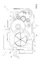
Figure 2 is a front view, with parts removed for clarity of the throttle valve ofFigure 1 ; -
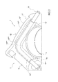
Figure 3 is a perspective view of a detail of the throttle valve ofFigure 1 , in particular of a conditioning circuit; -
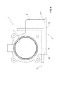
Figure 4 is a plan view with parts removed for clarity of the throttle valve ofFigure 1 ; -
Figure 5 is a perspective view of the conditioning circuit ofFigure 3 ; and -
Figures 6a) and 6b ) show two details of the conditioning circuit ofFigure 3 . - In
Figures 1 and2 , number 1 indicates as a whole a throttle valve with electronic control for an internal combustion engine (not illustrated). The throttle valve 1 comprises avalve body 2 housing an electric motor 3 (illustrated inFigure 2 ), atubular feeding duct 4 with circular section through which the air taken in by the internal combustion engine flows, and a throttle plate 5 (shown schematically in dashed lines), which has a circular shape, engages thefeeding duct 4 and rotates between an opening position and a closing position of thefeeding duct 4 due to the action of an actuating device. Thethrottle plate 5 is splined to ashaft 6 having a longitudinal rotation axis 7 to rotate between the opening position and the closing position due to the action of the actuating device. - As illustrated in
Figure 2 , the actuating device comprises theelectric motor 3 which is coupled to theshaft 6 itself by means of agear drive 8, a return spring (not shown and coupled to the shaft 6) suited to rotate thethrottle plate 5 towards the closing position, and a contrast spring (not shown and coupled to the shaft 6) suited to rotate thethrottle plate 5 towards a limp-home position defined by an abutment body (not shown) against the action of the return spring. - The
electric motor 3 has a cylindrical body, which is arranged in a tubular housing 9 (illustrated inFigure 1 ) of thevalve body 2 arranged next to thefeeding duct 4 and is maintained in a predetermined position inside thetubular housing 9 by a metal plate provided with a pair of female electric connectors 10 (illustrated inFigure 2 ), which are electrically connected to theelectric motor 3 and are suited to be engaged by a pair of respective male electric connectors 11 (illustrated inFigure 1 ). - The
gear drive 8 is arranged in a chamber 12 (shown inFigure 2 ) of thevalve body 2, which is defined by twoshells 13* and 13**, of which ashell 13* defining aremovable lid 13* (shown inFigure 1 ) and ashell 13** being arranged next to thefeeding duct 4 and next to thetubular housing 9. - As illustrated in
Figures 1 and2 , the throttle valve 1 comprises a position inductive sensor of a "contactless" type, which is coupled to theshaft 6 and is suited to detect the angular position of theshaft 6 and, therefore, of thethrottle plate 5 in order to allow a feedback control of the position of thethrottle plate 5 itself. The position sensor comprises a rotor 14 (shown inFigure 2 ) integral with theshaft 6 and a stator 15 (shown inFigure 1 ) carried by thelid 13* removable and in use arranged facing therotor 14. - As shown in
Figure 1 , theremovable lid 13* is provided with a femaleelectric connector 16, which comprises a series of electric contacts (not illustrated in detail): two electric contacts are connected to the maleelectric connectors 11 suited to feed theelectric motor 3, while the other electric contacts are attached to thestator 15 of the position sensor. - The
valve body 2 is entirely made of a first material, internally defines thefeeding duct 4, and comprises, among other things, thetubular housing 9 being arranged next to thefeeding duct 4 and houses theelectric motor 3 and thechamber 12, which houses thegear drive 8 and is closed by aremovable lid 13*. In other words, theshell 13**, thefeeding duct 4 and thetubular housing 9 are made of the first material. - According to a preferred embodiment, the material that makes up the valve body 2 (i.e., the
shell 13**, thefeeding duct 4 and the tubular housing 9) is a metal material, in particular aluminum. Preferably, thethrottle plate 5 is made with the same first metal material forming thevalve body 2; alternatively thethrottle plate 5 is made of a metal material that is different from the first metal material which forms thevalve body 2 but still has a behavior similar to the first metal material forming thevalve body 2. In this way, the two parts which cooperate together to define the closure of thefeeding duct 4 are made with the same material (or both metal materials similar to each other) and therefore allow substantially the same type of performance regarding both temperature variations and aging. - Finally, according to the embodiment illustrated in
Figures 3 and4 , thevalve body 2 comprises aconditioning circuit 17 which in turn comprises achannel 18 and apipe 19. Thechannel 18 is substantially L-shaped and has amajor branch 18* obtained in the upper portion of theshell 13**, aminor branch 18** obtained in the upper portion of thetubular housing 9 and a bentjoint segment 18*** between themajor branch 18* and theminor branch 18**. Inside thechannel 18 thepipe 19 is housed, which is made of a second material and is also substantially L-shaped having amajor branch 19*, aminor branch 19** and a bentjoint segment 19*** between the major branch and the minor branch. According to a preferred variant, the second material which makes up thepipe 19 is steel, preferably stainless steel. Thepipe 19 is in hydraulic communication with a pump (not illustrated) that circulates the conditioning fluid and feeds the same to the channel for conditioning the different parts of the throttle valve. - The valve body 2 (i.e., the
shell 13**, thefeeding duct 4 and the tubular housing 9) is made by fusion (normally die cast) with thepipe 19 inserted inside the mold and, if necessary, is subsequently machined. In other words, the first material forming the valve body 2 (i.e., theshell 13**, thefeeding duct 4 and the tubular housing 9) is injection molded around thepipe 19 so that the outer surface of thepipe 19 is arranged in contact with the inner surface of thechannel 18. - According to a preferred embodiment, inside the mold used for the production of the valve body 2 (i.e., the
shell 13**, thefeeding duct 4 and the tubular housing 9) by means of fusion (normally die cast) an abutment support element is housed that during the injection acts as an abutment and as a support for thepipe 19 to prevent movement of thepipe 19 itself. - As illustrated in detail in
Figures 5 and 6 , the support element is preferably arranged inside the mold at thebent joint segment 19*** of thepipe 19. - The
channel 18 is substantially L-shaped and has themajor branch 18*, which is obtained in the upper portion of theshell 13**, theminor branch 18**, which is obtained in the upper portion of thetubular housing 9 and the bentjoint segment 18*** between themajor branch 18* and theminor branch 18** and open on the upper part. In particular, thebent joint segment 18*** has atop window 20 the shape of which is complementary to the shape of the bearing element arranged inside the mold. - It appears obvious that the
conditioning circuit 17 may alternately be of different shapes other than the substantially L shape as described above. - In particular, according to different alternatives, the conditioning circuit 17 (i.e. the
channel 18 and the pipe 19) has a rectilinear shape and is obtained in the upper portion of theshell 13** or in the upper portion of thetubular housing 9. - The throttle valve 1 described above has numerous advantages.
- In the first place, the
valve body 2 of the throttle valve 1 described above is simple and inexpensive to manufacture, as it is easily manufactured by a injection overmoulding of the valve body 2 (i.e., theshell 13**, thefeeding duct 4 and the tubular housing 9) around thepipe 19. - Furthermore, the
valve body 2 of the throttle valve 1 described above has extremely reasonable weight and manufacturing cost. - Finally, the throttle valve 1 enables to prevent the passage of the conditioning fluid used in the conditioning circuit and contained inside the
pipe 19 towards, for example, theelectric motor 3, thefeeding duct 4 or towards the external environment during use regardless of the phenomena of aging.
Claims (11)
- A throttle valve (1) for an internal combustion engine; the throttle valve (1) comprises:a valve body (2);a tubular feeding duct (4), which is defined in the valve body (2) and through which the air taken in by the internal combustion engine flows; anda throttle plate (5), which is arranged inside the feeding duct (4) and is splined to a shaft (6) mounted in a rotary manner, so as to rotate around a rotation axis (7) between a maximum opening position and a closing position to open and close the feeding duct (4);an actuating device, which controls the rotation of the throttle plate (5) around the rotation axis (7) and comprises an electric motor (3) as well as a gear drive (8), which transmits the motion from the electric motor (3) to the shaft (6) of the throttle plate (5);an actuating device conditioning circuit (17) defined in the valve body (2);the throttle valve (1) is characterised in that the valve body (2) is entirely made of a first metal material and the conditioning circuit (17) comprises a pipe (19) made of a second metal material, and wherein the valve body (2) is injection-overmoulded around the pipe (19).
- A valve according to claim 1, wherein the second metal material is steel, preferably stainless steel.
- A valve according to claim 1 or 2, wherein the first metal material is aluminium.
- A valve according to any of the previous claims, wherein the throttle plate (5) is made of the same first material that makes up the valve body (2).
- A valve according to any of the previous claims, wherein the valve body (2) comprises a tubular housing (9), which is arranged next to the feeding duct (4) and houses the electric motor (3); and wherein the gear drive (8) is arranged in a chamber (12) of the valve body (2), which is defined by two shells (13*, 13**), a first shell (13*) defining a removable lid (13*) and a second shell (13**) being arranged next to the feeding duct (4) and next to the tubular housing (9).
- A valve according to claim 5, wherein the pipe (19) comprises a first branch (19*), which is housed in the upper portion of the second shell (13**).
- A valve according to claim 5 or 6, wherein the pipe (19) comprises a second branch (19**), which is housed in the upper portion of the tubular housing (9).
- A valve according to claims 6 and 7, wherein the pipe (19) is substantially L-shaped.
- A valve according to claim 8, wherein the pipe (19) comprises a joint segment (19***) joining the first branch (19*) housed in the upper portion of the second shell (13**) to the second branch (19**) housed in the upper portion of the tubular housing (9).
- A valve according to claim 9, wherein the conditioning circuit (17) comprises a channel (18), which is obtained in the valve body (2), is made of the first metal material, and is designed to house the pipe (19); wherein the channel (18) comprises a first branch (18*), which is obtained in the upper portion of the second shell (13**), a second branch (18**), which is obtained in the upper portion of the tubular housing (8), and a joint segment (18***), which joins the first branch (18*) and the second branch (18**) together.
- A valve according to claim 10, wherein the bent joint segment (18***) between the first branch (18*) and the second branch (18**) is open on the upper part.
Applications Claiming Priority (1)
| Application Number | Priority Date | Filing Date | Title |
|---|---|---|---|
| ITBO20140140 | 2014-03-19 |
Publications (2)
| Publication Number | Publication Date |
|---|---|
| EP2921687A1 true EP2921687A1 (en) | 2015-09-23 |
| EP2921687B1 EP2921687B1 (en) | 2017-01-04 |
Family
ID=50486952
Family Applications (1)
| Application Number | Title | Priority Date | Filing Date |
|---|---|---|---|
| EP15159960.2A Active EP2921687B1 (en) | 2014-03-19 | 2015-03-19 | Throttle valve for an internal combustion engine provided with a conditioning circuit |
Country Status (2)
| Country | Link |
|---|---|
| US (1) | US20150267622A1 (en) |
| EP (1) | EP2921687B1 (en) |
Cited By (1)
| Publication number | Priority date | Publication date | Assignee | Title |
|---|---|---|---|---|
| EP3173610A1 (en) | 2015-11-26 | 2017-05-31 | Magneti Marelli S.p.A. | Intake pipe for an internal combustion engine provided with a thermoelectric conversion device and internal combustion engine provided with such a pipe |
Families Citing this family (2)
| Publication number | Priority date | Publication date | Assignee | Title |
|---|---|---|---|---|
| EP3037643B1 (en) * | 2014-12-22 | 2018-08-29 | Magneti Marelli S.p.A. | Electromechanical actuator for an internal combustion engine provided with a conditioning circuit |
| FR3131619B1 (en) | 2022-01-04 | 2026-04-24 | Valeo Systemes De Controle Moteur | VALVE BODY AND ACTUATOR COMPRISING SUCH A VALVE BODY |
Citations (4)
| Publication number | Priority date | Publication date | Assignee | Title |
|---|---|---|---|---|
| JPH11179817A (en) * | 1997-12-24 | 1999-07-06 | Honda Motor Co Ltd | Throttle body manufacturing method |
| EP1126154A2 (en) * | 2000-02-16 | 2001-08-22 | Denso Corporation | Throttle body for an internal combustion engine and its manufacturing method and a throttle apparatus using the same |
| DE102007053329A1 (en) * | 2007-06-19 | 2008-12-24 | Kia Motors Corporation | Magnesium throttle body and method of making same |
| DE202013005082U1 (en) * | 2012-06-06 | 2013-10-17 | MAGNETI MARELLI S.p.A. | A throttle valve for an internal combustion engine, which is provided with a metallic valve seat inside which a valve body made of plastic material is injection-molded |
Family Cites Families (6)
| Publication number | Priority date | Publication date | Assignee | Title |
|---|---|---|---|---|
| US2529572A (en) * | 1946-01-15 | 1950-11-14 | Weatherhead Co | Carburetor valve |
| US5396866A (en) * | 1993-12-27 | 1995-03-14 | Kuntz; Dennis R. | Ram tube |
| US7137614B2 (en) * | 2003-10-15 | 2006-11-21 | Aisan Kogyo Kabushiki Kaisha | Valve devices for controlling flow of intake air |
| JP4353291B2 (en) * | 2007-09-20 | 2009-10-28 | 株式会社デンソー | Valve open / close control device |
| KR20130067883A (en) * | 2011-12-14 | 2013-06-25 | 현대자동차주식회사 | Automotive chamber structure |
| DE102012223156A1 (en) * | 2012-12-14 | 2014-06-18 | Continental Automotive Gmbh | Housing and method of manufacturing the housing |
-
2015
- 2015-03-18 US US14/661,208 patent/US20150267622A1/en not_active Abandoned
- 2015-03-19 EP EP15159960.2A patent/EP2921687B1/en active Active
Patent Citations (4)
| Publication number | Priority date | Publication date | Assignee | Title |
|---|---|---|---|---|
| JPH11179817A (en) * | 1997-12-24 | 1999-07-06 | Honda Motor Co Ltd | Throttle body manufacturing method |
| EP1126154A2 (en) * | 2000-02-16 | 2001-08-22 | Denso Corporation | Throttle body for an internal combustion engine and its manufacturing method and a throttle apparatus using the same |
| DE102007053329A1 (en) * | 2007-06-19 | 2008-12-24 | Kia Motors Corporation | Magnesium throttle body and method of making same |
| DE202013005082U1 (en) * | 2012-06-06 | 2013-10-17 | MAGNETI MARELLI S.p.A. | A throttle valve for an internal combustion engine, which is provided with a metallic valve seat inside which a valve body made of plastic material is injection-molded |
Cited By (1)
| Publication number | Priority date | Publication date | Assignee | Title |
|---|---|---|---|---|
| EP3173610A1 (en) | 2015-11-26 | 2017-05-31 | Magneti Marelli S.p.A. | Intake pipe for an internal combustion engine provided with a thermoelectric conversion device and internal combustion engine provided with such a pipe |
Also Published As
| Publication number | Publication date |
|---|---|
| EP2921687B1 (en) | 2017-01-04 |
| US20150267622A1 (en) | 2015-09-24 |
Similar Documents
| Publication | Publication Date | Title |
|---|---|---|
| US9353706B2 (en) | Actuator and valve arrangement | |
| US9945283B2 (en) | Multiport valve with modular rotor | |
| EP2921687B1 (en) | Throttle valve for an internal combustion engine provided with a conditioning circuit | |
| CN105276199B (en) | Electric valve | |
| US7007925B2 (en) | Electrohydraulic valve having an armature with a rolling bearing | |
| EP2264318A1 (en) | A variable-displacement lubricant pump | |
| US20150184584A1 (en) | Rotational drive apparatus | |
| CN112780801B (en) | Valve device | |
| EP2921750A1 (en) | A valve | |
| US9726173B2 (en) | Variable displacement lubricant pump for an internal combustion engine with a temperature control valve | |
| CN108603469B (en) | Pumping assembly for feeding fuel, preferably diesel fuel, to an internal combustion engine | |
| KR20120105008A (en) | System for feeding fuel from a tank to an internal combustion engine | |
| ITBO20120312A1 (en) | BUTTERFLY VALVE FOR AN INTERNAL COMBUSTION ENGINE PROVIDED WITH A METALLIC VALVE SEAT MOLDED INSIDE A BODY VALVE IN PLASTIC MATERIAL | |
| US10968840B2 (en) | Method to manufacture a throttle valve for an internal combustion engine provided with a conditioning circuit | |
| KR20160093607A (en) | Actuator | |
| EP2881564B1 (en) | Throttle valve for an internal combustion engine provided with a metal valve seat overmoulded inside a valve body made of a plastic material | |
| US20190055942A1 (en) | Pumping assembly to feed fuel, preferably diesel fuel, to an internal combustion engine | |
| JP5943007B2 (en) | Sensor module | |
| CN105793526B (en) | Rotor for a camshaft adjuster, kit of parts for producing a rotor for a camshaft adjuster, and method for producing a joined component, preferably a rotor for a camshaft adjuster | |
| EP3164602B1 (en) | Overflow valve for a fuel feed system and method for production of such a valve | |
| EP3060807B1 (en) | Variable displacement lubricant pump | |
| CN103375583B (en) | The hydraulic servo control system of SERVO CONTROL gearbox | |
| EP1939432A1 (en) | Servo controlled valve with cylindrical shutter for adjusting the intake air flow rate in an internal combustion engine | |
| CN111379888A (en) | Die assembly and valve block manufacturing method | |
| WO2013174610A1 (en) | Pressure limiting valve and fuel injecion plant for an internal combustion engine comprising said pressure limiting valve |
Legal Events
| Date | Code | Title | Description |
|---|---|---|---|
| PUAI | Public reference made under article 153(3) epc to a published international application that has entered the european phase |
Free format text: ORIGINAL CODE: 0009012 |
|
| AK | Designated contracting states |
Kind code of ref document: A1 Designated state(s): AL AT BE BG CH CY CZ DE DK EE ES FI FR GB GR HR HU IE IS IT LI LT LU LV MC MK MT NL NO PL PT RO RS SE SI SK SM TR |
|
| AX | Request for extension of the european patent |
Extension state: BA ME |
|
| 17P | Request for examination filed |
Effective date: 20151112 |
|
| GRAP | Despatch of communication of intention to grant a patent |
Free format text: ORIGINAL CODE: EPIDOSNIGR1 |
|
| INTG | Intention to grant announced |
Effective date: 20160729 |
|
| GRAS | Grant fee paid |
Free format text: ORIGINAL CODE: EPIDOSNIGR3 |
|
| GRAA | (expected) grant |
Free format text: ORIGINAL CODE: 0009210 |
|
| AK | Designated contracting states |
Kind code of ref document: B1 Designated state(s): AL AT BE BG CH CY CZ DE DK EE ES FI FR GB GR HR HU IE IS IT LI LT LU LV MC MK MT NL NO PL PT RO RS SE SI SK SM TR |
|
| REG | Reference to a national code |
Ref country code: GB Ref legal event code: FG4D |
|
| REG | Reference to a national code |
Ref country code: CH Ref legal event code: EP |
|
| REG | Reference to a national code |
Ref country code: AT Ref legal event code: REF Ref document number: 859481 Country of ref document: AT Kind code of ref document: T Effective date: 20170115 |
|
| REG | Reference to a national code |
Ref country code: IE Ref legal event code: FG4D |
|
| REG | Reference to a national code |
Ref country code: FR Ref legal event code: PLFP Year of fee payment: 3 |
|
| REG | Reference to a national code |
Ref country code: DE Ref legal event code: R096 Ref document number: 602015001180 Country of ref document: DE |
|
| REG | Reference to a national code |
Ref country code: LT Ref legal event code: MG4D Ref country code: NL Ref legal event code: MP Effective date: 20170104 |
|
| REG | Reference to a national code |
Ref country code: AT Ref legal event code: MK05 Ref document number: 859481 Country of ref document: AT Kind code of ref document: T Effective date: 20170104 |
|
| PG25 | Lapsed in a contracting state [announced via postgrant information from national office to epo] |
Ref country code: NL Free format text: LAPSE BECAUSE OF FAILURE TO SUBMIT A TRANSLATION OF THE DESCRIPTION OR TO PAY THE FEE WITHIN THE PRESCRIBED TIME-LIMIT Effective date: 20170104 |
|
| PG25 | Lapsed in a contracting state [announced via postgrant information from national office to epo] |
Ref country code: IS Free format text: LAPSE BECAUSE OF FAILURE TO SUBMIT A TRANSLATION OF THE DESCRIPTION OR TO PAY THE FEE WITHIN THE PRESCRIBED TIME-LIMIT Effective date: 20170504 Ref country code: FI Free format text: LAPSE BECAUSE OF FAILURE TO SUBMIT A TRANSLATION OF THE DESCRIPTION OR TO PAY THE FEE WITHIN THE PRESCRIBED TIME-LIMIT Effective date: 20170104 Ref country code: LT Free format text: LAPSE BECAUSE OF FAILURE TO SUBMIT A TRANSLATION OF THE DESCRIPTION OR TO PAY THE FEE WITHIN THE PRESCRIBED TIME-LIMIT Effective date: 20170104 Ref country code: NO Free format text: LAPSE BECAUSE OF FAILURE TO SUBMIT A TRANSLATION OF THE DESCRIPTION OR TO PAY THE FEE WITHIN THE PRESCRIBED TIME-LIMIT Effective date: 20170404 Ref country code: GR Free format text: LAPSE BECAUSE OF FAILURE TO SUBMIT A TRANSLATION OF THE DESCRIPTION OR TO PAY THE FEE WITHIN THE PRESCRIBED TIME-LIMIT Effective date: 20170405 Ref country code: HR Free format text: LAPSE BECAUSE OF FAILURE TO SUBMIT A TRANSLATION OF THE DESCRIPTION OR TO PAY THE FEE WITHIN THE PRESCRIBED TIME-LIMIT Effective date: 20170104 |
|
| PG25 | Lapsed in a contracting state [announced via postgrant information from national office to epo] |
Ref country code: PT Free format text: LAPSE BECAUSE OF FAILURE TO SUBMIT A TRANSLATION OF THE DESCRIPTION OR TO PAY THE FEE WITHIN THE PRESCRIBED TIME-LIMIT Effective date: 20170504 Ref country code: PL Free format text: LAPSE BECAUSE OF FAILURE TO SUBMIT A TRANSLATION OF THE DESCRIPTION OR TO PAY THE FEE WITHIN THE PRESCRIBED TIME-LIMIT Effective date: 20170104 Ref country code: ES Free format text: LAPSE BECAUSE OF FAILURE TO SUBMIT A TRANSLATION OF THE DESCRIPTION OR TO PAY THE FEE WITHIN THE PRESCRIBED TIME-LIMIT Effective date: 20170104 Ref country code: BG Free format text: LAPSE BECAUSE OF FAILURE TO SUBMIT A TRANSLATION OF THE DESCRIPTION OR TO PAY THE FEE WITHIN THE PRESCRIBED TIME-LIMIT Effective date: 20170404 Ref country code: SE Free format text: LAPSE BECAUSE OF FAILURE TO SUBMIT A TRANSLATION OF THE DESCRIPTION OR TO PAY THE FEE WITHIN THE PRESCRIBED TIME-LIMIT Effective date: 20170104 Ref country code: AT Free format text: LAPSE BECAUSE OF FAILURE TO SUBMIT A TRANSLATION OF THE DESCRIPTION OR TO PAY THE FEE WITHIN THE PRESCRIBED TIME-LIMIT Effective date: 20170104 Ref country code: RS Free format text: LAPSE BECAUSE OF FAILURE TO SUBMIT A TRANSLATION OF THE DESCRIPTION OR TO PAY THE FEE WITHIN THE PRESCRIBED TIME-LIMIT Effective date: 20170104 Ref country code: LV Free format text: LAPSE BECAUSE OF FAILURE TO SUBMIT A TRANSLATION OF THE DESCRIPTION OR TO PAY THE FEE WITHIN THE PRESCRIBED TIME-LIMIT Effective date: 20170104 |
|
| REG | Reference to a national code |
Ref country code: DE Ref legal event code: R097 Ref document number: 602015001180 Country of ref document: DE |
|
| PG25 | Lapsed in a contracting state [announced via postgrant information from national office to epo] |
Ref country code: EE Free format text: LAPSE BECAUSE OF FAILURE TO SUBMIT A TRANSLATION OF THE DESCRIPTION OR TO PAY THE FEE WITHIN THE PRESCRIBED TIME-LIMIT Effective date: 20170104 Ref country code: RO Free format text: LAPSE BECAUSE OF FAILURE TO SUBMIT A TRANSLATION OF THE DESCRIPTION OR TO PAY THE FEE WITHIN THE PRESCRIBED TIME-LIMIT Effective date: 20170104 Ref country code: CZ Free format text: LAPSE BECAUSE OF FAILURE TO SUBMIT A TRANSLATION OF THE DESCRIPTION OR TO PAY THE FEE WITHIN THE PRESCRIBED TIME-LIMIT Effective date: 20170104 Ref country code: SK Free format text: LAPSE BECAUSE OF FAILURE TO SUBMIT A TRANSLATION OF THE DESCRIPTION OR TO PAY THE FEE WITHIN THE PRESCRIBED TIME-LIMIT Effective date: 20170104 |
|
| PLBE | No opposition filed within time limit |
Free format text: ORIGINAL CODE: 0009261 |
|
| STAA | Information on the status of an ep patent application or granted ep patent |
Free format text: STATUS: NO OPPOSITION FILED WITHIN TIME LIMIT |
|
| PG25 | Lapsed in a contracting state [announced via postgrant information from national office to epo] |
Ref country code: MC Free format text: LAPSE BECAUSE OF FAILURE TO SUBMIT A TRANSLATION OF THE DESCRIPTION OR TO PAY THE FEE WITHIN THE PRESCRIBED TIME-LIMIT Effective date: 20170104 Ref country code: SM Free format text: LAPSE BECAUSE OF FAILURE TO SUBMIT A TRANSLATION OF THE DESCRIPTION OR TO PAY THE FEE WITHIN THE PRESCRIBED TIME-LIMIT Effective date: 20170104 Ref country code: DK Free format text: LAPSE BECAUSE OF FAILURE TO SUBMIT A TRANSLATION OF THE DESCRIPTION OR TO PAY THE FEE WITHIN THE PRESCRIBED TIME-LIMIT Effective date: 20170104 |
|
| REG | Reference to a national code |
Ref country code: IE Ref legal event code: MM4A |
|
| PG25 | Lapsed in a contracting state [announced via postgrant information from national office to epo] |
Ref country code: LU Free format text: LAPSE BECAUSE OF NON-PAYMENT OF DUE FEES Effective date: 20170319 |
|
| REG | Reference to a national code |
Ref country code: FR Ref legal event code: PLFP Year of fee payment: 4 |
|
| PG25 | Lapsed in a contracting state [announced via postgrant information from national office to epo] |
Ref country code: IE Free format text: LAPSE BECAUSE OF NON-PAYMENT OF DUE FEES Effective date: 20170319 Ref country code: SI Free format text: LAPSE BECAUSE OF FAILURE TO SUBMIT A TRANSLATION OF THE DESCRIPTION OR TO PAY THE FEE WITHIN THE PRESCRIBED TIME-LIMIT Effective date: 20170104 |
|
| REG | Reference to a national code |
Ref country code: BE Ref legal event code: MM Effective date: 20170331 |
|
| PG25 | Lapsed in a contracting state [announced via postgrant information from national office to epo] |
Ref country code: BE Free format text: LAPSE BECAUSE OF NON-PAYMENT OF DUE FEES Effective date: 20170331 |
|
| PG25 | Lapsed in a contracting state [announced via postgrant information from national office to epo] |
Ref country code: MT Free format text: LAPSE BECAUSE OF NON-PAYMENT OF DUE FEES Effective date: 20170319 |
|
| REG | Reference to a national code |
Ref country code: CH Ref legal event code: PL |
|
| PG25 | Lapsed in a contracting state [announced via postgrant information from national office to epo] |
Ref country code: CH Free format text: LAPSE BECAUSE OF NON-PAYMENT OF DUE FEES Effective date: 20180331 Ref country code: LI Free format text: LAPSE BECAUSE OF NON-PAYMENT OF DUE FEES Effective date: 20180331 |
|
| PG25 | Lapsed in a contracting state [announced via postgrant information from national office to epo] |
Ref country code: HU Free format text: LAPSE BECAUSE OF FAILURE TO SUBMIT A TRANSLATION OF THE DESCRIPTION OR TO PAY THE FEE WITHIN THE PRESCRIBED TIME-LIMIT; INVALID AB INITIO Effective date: 20150319 |
|
| PG25 | Lapsed in a contracting state [announced via postgrant information from national office to epo] |
Ref country code: CY Free format text: LAPSE BECAUSE OF FAILURE TO SUBMIT A TRANSLATION OF THE DESCRIPTION OR TO PAY THE FEE WITHIN THE PRESCRIBED TIME-LIMIT Effective date: 20170104 |
|
| GBPC | Gb: european patent ceased through non-payment of renewal fee |
Effective date: 20190319 |
|
| PG25 | Lapsed in a contracting state [announced via postgrant information from national office to epo] |
Ref country code: MK Free format text: LAPSE BECAUSE OF FAILURE TO SUBMIT A TRANSLATION OF THE DESCRIPTION OR TO PAY THE FEE WITHIN THE PRESCRIBED TIME-LIMIT Effective date: 20170104 |
|
| PG25 | Lapsed in a contracting state [announced via postgrant information from national office to epo] |
Ref country code: GB Free format text: LAPSE BECAUSE OF NON-PAYMENT OF DUE FEES Effective date: 20190319 |
|
| PG25 | Lapsed in a contracting state [announced via postgrant information from national office to epo] |
Ref country code: AL Free format text: LAPSE BECAUSE OF FAILURE TO SUBMIT A TRANSLATION OF THE DESCRIPTION OR TO PAY THE FEE WITHIN THE PRESCRIBED TIME-LIMIT Effective date: 20170104 |
|
| PGFP | Annual fee paid to national office [announced via postgrant information from national office to epo] |
Ref country code: DE Payment date: 20260219 Year of fee payment: 12 |
|
| PGFP | Annual fee paid to national office [announced via postgrant information from national office to epo] |
Ref country code: IT Payment date: 20260219 Year of fee payment: 12 |
|
| PGFP | Annual fee paid to national office [announced via postgrant information from national office to epo] |
Ref country code: FR Payment date: 20260219 Year of fee payment: 12 |
|
| PGFP | Annual fee paid to national office [announced via postgrant information from national office to epo] |
Ref country code: TR Payment date: 20260225 Year of fee payment: 12 |