EP3173573B1 - Sphärische bohrlochschieber-ringdichtung - Google Patents
Sphärische bohrlochschieber-ringdichtung Download PDFInfo
- Publication number
- EP3173573B1 EP3173573B1 EP16002455.0A EP16002455A EP3173573B1 EP 3173573 B1 EP3173573 B1 EP 3173573B1 EP 16002455 A EP16002455 A EP 16002455A EP 3173573 B1 EP3173573 B1 EP 3173573B1
- Authority
- EP
- European Patent Office
- Prior art keywords
- spherical
- blow out
- out preventer
- annular seal
- pipe
- Prior art date
- Legal status (The legal status is an assumption and is not a legal conclusion. Google has not performed a legal analysis and makes no representation as to the accuracy of the status listed.)
- Active
Links
Images


Classifications
-
- E—FIXED CONSTRUCTIONS
- E21—EARTH OR ROCK DRILLING; MINING
- E21B—EARTH OR ROCK DRILLING; OBTAINING OIL, GAS, WATER, SOLUBLE OR MELTABLE MATERIALS OR A SLURRY OF MINERALS FROM WELLS
- E21B33/00—Sealing or packing boreholes or wells
- E21B33/02—Surface sealing or packing
- E21B33/03—Well heads; Setting-up thereof
- E21B33/06—Blow-out preventers, i.e. apparatus closing around a drill pipe, e.g. annular blow-out preventers
-
- E—FIXED CONSTRUCTIONS
- E21—EARTH OR ROCK DRILLING; MINING
- E21B—EARTH OR ROCK DRILLING; OBTAINING OIL, GAS, WATER, SOLUBLE OR MELTABLE MATERIALS OR A SLURRY OF MINERALS FROM WELLS
- E21B33/00—Sealing or packing boreholes or wells
- E21B33/02—Surface sealing or packing
- E21B33/08—Wipers; Oil savers
- E21B33/085—Rotatable packing means, e.g. rotating blow-out preventers
Definitions
- the present disclosure relates to a spherical blow out preventer annular seal for use on a drilling rig.
- blow out preventer In oil well drilling operations, subsurface high pressure gas pockets can be encountered.
- a blow out preventer is required to prevent the release of the high pressure upwards through the drilling hole.
- Blow out preventers are mounted in a housing surrounding a drill hole.
- Typical blow out preventers have a resilient sealing means which can be caused to tightly grip the outer circumferential surfaces of various diameter drill string components to prevent pressure from subterranean gas pockets from blowing out material along the drilling string.
- Most oil well blow out preventers are remotely activated, as by a hydraulically actuated piston. Drilling activities are reaching into deeper and harder reservoirs and existing blow out preventer products are being challenged to function at higher temperatures and pressures.
- the conventional anti-extrusion barrier is designed to close on the largest diameter drill pipe and its operating range does not eliminate the gap in the anti-extrusion barrier which remains when closing on small pipe sizes. This gap is filled with compressed elastomer and is prone to be extruded at elevated temperature and pressure, causing a leak path for the contained fluids.
- a spherical blow out preventer annular seal is provided for sealing around a pipe.
- the blow out preventer includes a housing adapted to be disposed around the pipe and having a generally spherical interior surface.
- a seal body includes a plurality of metallic inserts arranged side by side in an annular pattern and each includes a base portion and a wedge shaped extension having a partially spherical outer surface terminating at a tip end.
- An annular elastomeric body is over-molded on the base portions of the plurality of metallic inserts with the partially spherical outer surface of each of the wedge shaped extensions being supported in engagement with the interior spherical surface of the housing.
- a piston is engaged with the seal body to press the metallic inserts upward and inward against the generally spherical interior surface of the housing so as to come together tangentially around the pipe.
- the upward movement of the hydraulic piston in a spherical blow out preventer drives the metals segments upward and inward to form an anti-extrusion barrier and at the same time forces the rubber into a smaller space thus moving it inward to build contact pressure against the pipe, thus effecting a seal.
- the tangential movement of the inserts of the present disclosure allow further upward movement of the piston after the metal segments have made contact with the pipe or with each other. This is achieved by the tangential movement of segments relative to each other. This allows use of longer segments resulting in smaller extrusion gaps while providing improved contact stress and thus improved sealing functions across different pipe diameters in a certain range.
- Example embodiments are provided so that this disclosure will be thorough, and will fully convey the scope to those who are skilled in the art. Numerous specific details are set forth such as examples of specific components, devices, and methods, to provide a thorough understanding of embodiments of the present disclosure. It will be apparent to those skilled in the art that specific details need not be employed, that example embodiments may be embodied in many different forms and that neither should be construed to limit the scope of the disclosure. In some example embodiments, well-known processes, well-known device structures, and well-known technologies are not described in detail.
- first, second, third, etc. may be used herein to describe various elements, components, regions, layers and/or sections, these elements, components, regions, layers and/or sections should not be limited by these terms. These terms may be only used to distinguish one element, component, region, layer or section from another region, layer or section. Terms such as “first,” “second,” and other numerical terms when used herein do not imply a sequence or order unless clearly indicated by the context. Thus, a first element, component, region, layer or section discussed below could be termed a second element, component, region, layer or section without departing from the teachings of the example embodiments.
- spatially relative terms such as “inner,” “outer,” “beneath,” “below,” “lower,” “above,” “upper,” and the like, may be used herein for ease of description to describe one element or feature's relationship to another element(s) or feature(s) as illustrated in the figures.
- Spatially relative terms may be intended to encompass different orientations of the device in use or operation in addition to the orientation depicted in the figures. For example, if the device in the figures is turned over, elements described as “below” or “beneath” other elements or features would then be oriented “above” the other elements or features.
- the example term “below” can encompass both an orientation of above and below.
- the device may be otherwise oriented (rotated 90 degrees or at other orientations) and the spatially relative descriptors used herein interpreted accordingly.
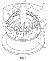
- the spherical blow out preventer 10 includes an annular housing 12 (shown in partial cutaway view for illustrative purposes) having an opening 14 receiving a pipe 16 and having a generally spherical interior surface 18.
- the annular housing 12 can be made of steel, other metals or other materials that can withstand high temperatures and pressures.
- a seal body 20 is disposed within the annular housing 12.
- the seal body 20 includes a plurality of metallic inserts 22 arranged in a side-by-side annular pattern.
- the metallic inserts 22 include a base portion 24 and a wedge-shaped extension 26 having a partially spherical outer surface 28 terminating at a tip end 30.
- an annular elastomeric body 32 is over-molded on the base portions 24 of the plurality or metallic inserts 22. The elastomeric body 32 supports each of the metallic inserts 22 with the partially spherical outer surface 28 of each of the wedge-shaped extensions 26 being supported in engagement with the interior spherical surface 18 of the annular housing 12.
- the elastomeric body 32 includes a partially spherical outer surface 34, a generally cylindrical inner surface 36 and a generally conical inner surface 38 extending from the generally cylindrical inner surface 36.
- the elastomeric body 32 may define a recessed gap region 40 in the elastomeric body between each metallic insert 22.
- the gap region 40 can include a generally conical-shaped outer surface 42 although other shapes may be used.
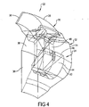
- FIG. 4 cut away views of a segment of the seal body 20 are shown with a metallic insert 22 shown over-molded within the elastomeric body 32.
- the base portion 24 includes an enlarged shoe region 44 and a relatively narrower neck region 46 extending between the shoe region 44 and the wedge shaped extension 26.
- the shoe region 44 can include a generally flat or planar surface 48 on a side facing the neck portion 46 and an arcuate surface 50 on a side facing away from the neck portion 46.
- the metallic inserts 22 are positioned so that the tip ends 30 point in a direction that is offset from a center axis "A" of the seal body 20.
- the base portion 24 can be generally symmetric about a plane P that passes through a center axis of the seal body 20 while the wedge shaped extension 26 is skewed so that the plane of symmetry P of the base portion 24 intersects a side wall 54 of the wedge shaped extension 26.
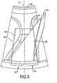
- a piston 52 is disposed against the seal body 20. The piston 52 can be actuated to press the metallic inserts 22 upward and inward against the generally spherical interior surface 18 of the housing 12.
- the wedge shaped extensions 26 come together tangentially around the pipe to the position as shown in Figure 3 .
- the metallic inserts 22 are spaced from one another by a first predetermined distance and when they are moved to the deformed position, illustrated in Figure 3 , the wedge shaped extensions 26 move radially inward and circumferentially to come together tangentially around the pipe 16.
- the tip ends 30 of each of the wedge-shaped extensions 26 are positioned directly adjacent to the side surface 54 of an adjacent wedge-shaped extension 26 at a location that is spaced from the tip end 30 of the adjacent wedge-shaped extension 26.
- the wedge-shaped extensions 26 combine to form an anti-extrusion barrier with the wedge-shaped extensions 26 making contact with the pipe 16 and/or with each other resulting in smaller extrusion gaps that are essential under higher temperature and pressure applications.
- 14 metallic inserts 22 are shown, however it should be understood that more or fewer inserts can be utilized depending upon the desired application.
- the tangential movement of the inserts 22 also allows for the use of longer wedge-shaped extensions 26 resulting in smaller extrusion gaps when used across different pipe diameters within a certain range.
Landscapes
- Life Sciences & Earth Sciences (AREA)
- Engineering & Computer Science (AREA)
- Geology (AREA)
- Mining & Mineral Resources (AREA)
- Physics & Mathematics (AREA)
- Environmental & Geological Engineering (AREA)
- Fluid Mechanics (AREA)
- General Life Sciences & Earth Sciences (AREA)
- Geochemistry & Mineralogy (AREA)
- Gasket Seals (AREA)
Claims (13)
- Sphärische Ringdichtung für einen Blowout-Preventer zur Abdichtung um ein Rohr (16), umfassend:ein Gehäuse (12), welches zur Anordnung um das Rohr (16) herum vorgesehen ist und eine allgemein sphärische Innenfläche (18) aufweist;einen Dichtungskörper (20), der eine Vielzahl metallischer Einsätze (22), die nebeneinander in einem ringförmigen Muster angeordnet sind und jeweils einen Basisabschnitt (24) und einen keilförmigen Fortsatz (26) mit einer teilweise sphärischen Außenfläche (28) einschließen, die in einem Spitzenende (30) endet, und einen ringförmigen Elastomerkörper (32) einschließt, mit dem die Basisabschnitte (24) der Vielzahl metallischer Einsätze (22) umspritzt sind, wobei die teilweise sphärische Außenfläche (28) von jedem der keilförmigen Fortsätze (26) Träger in Eingriff mit der sphärischen Innenfläche (18) des Gehäuses (12) sind;einen Kolben (52) in Eingriff mit dem Dichtungkörper (20), um die metallischen Einsätze (22) aufwärts und einwärts gegen die allgemein sphärische Innenfläche (18) des Gehäuses (12) zu pressen, um so tangential um das Rohr (16) herum zusammen zu kommen;dadurch gekennzeichnet, dass die Spitzenenden (30) der Einsätze (22) in eine Richtung weisen, die von einer Mittelachse (A) des Dichtungskörpers (20) versetzt ist,wobei die Einsätze (22) in einer nicht verformten Position des Dichtungskörpers (20) voneinander um eine erste vorbestimmte Distanz beabstandet sind,und wobei die keilförmigen Fortsätze (26) in einer verformten Position des Dichtungskörpers (20) radial einwärts und im Umkreis zusammen tangential um das Rohr (16) herum angeordnet sind und die Spitzenenden (30) von jedem der Fortsätze (26) direkt benachbart zu einer Seitenfläche (54) eines Fortsatzes (26) an einer Stelle positioniert sind,die von dem Spitzenende (30) des benachbarten Fortsatzes (26) beabstandet ist.
- Sphärische Ringdichtung für einen Blowout-Preventer nach Anspruch 1, wobei der ringförmige Elastomerkörper (32) eine teilweise sphärische Außenfläche (34) aufweist.
- Sphärische Ringdichtung für einen Blowout-Preventer nach einem der Ansprüche 1 oder 2, wobei der ringförmige Elastomerkörper (32) eine allgemein zylindrische Innenfläche (36) einschließt.
- Sphärische Ringdichtung für einen Blowout-Preventer nach Anspruch 3, wobei der ringförmige Elastomerkörper (32) eine konische Innenfläche (38) einschließt, die sich von der allgemein zylindrischen Innenfläche (36) erstreckt.
- Sphärische Ringdichtung für einen Blowout-Preventer nach einem der Ansprüche 1 bis 4, wobei die metallischen Einsätze (22) in einem nicht verformten Zustand des Dichtungskörpers (20) voneinander um eine erste Distanz beabstandet sind und in einem verformten Zustand des Dichtungskörpers (20) zusammen tangential um das Rohr (16) herum angeordnet sind.
- Sphärische Ringdichtung für einen Blowout-Preventer nach einem der Ansprüche 1 bis 5, wobei das Spitzenenden (30) von jedem der keilförmigen Fortsätze (26), wenn die metallischen Einsätze (22) zusammen tangential um das Rohr (16) herum angeordnet sind, sich direkt benachbart zu einer Seitenfläche (54) eines benachbarten keilförmigen Fortsatzes (26) an einer Stelle befinden, die von dem Spitzenende (30) des benachbarten keilförmigen Fortsatzes (26) beabstandet ist.
- Sphärische Ringdichtung für einen Blowout-Preventer nach einem der Ansprüche 1 bis 6, wobei der Basisabschnitt (24) der metallischen Einsätze (22) einen vergrößerten Fußbereich (44) und einen relativ engeren Halsbereich (46) aufweist, der zwischen dem Fußbereich (44) und dem keilförmigen Fortsatz (26) angeordnet ist.
- Sphärische Ringdichtung für einen Blowout-Preventer nach Anspruch 7, wobei der vergrößerte Fußbereich (44) eine allgemein ebene Fläche (48) auf einer Seite, die zu dem Halsabschnitt (46) weist, und eine bogenförmige Fläche (50) an einer Seite einschließt, die von dem Halsabschnitt (46) weg weist.
- Sphärische Ringdichtung für einen Blowout-Preventer nach einem der Ansprüche 1 bis 8, wobei die metallischen Einsätze (22) so positioniert sind, das die Spitzenenden (30) in eine Richtung weisen, die sowohl im nicht verformten Zustand als auch im verformten Zustand von einer Mittelachse des Dichtungskörpers (20) versetzt ist.
- Sphärische Ringdichtung für einen Blowout-Preventer nach einem der Ansprüche 1 bis 9, wobei die keilförmigen Fortsätze (26) relativ zu dem Rohr (16) sowohl in eine radial einwärtige als auch in eine Umkreisrichtung beweglich sind.
- Sphärische Ringdichtung für einen Blowout-Preventer nach einem der Ansprüche 1 bis 10, wobei die metallischen Einsätze (22) enger zusammen positioniert sind, wenn die metallischen Einsätze (22) in einem verformten Zustand aufwärts und einwärts gegen die allgemein sphärische Innenfläche (18) des Gehäuses (12) gepresst werden.
- Sphärische Ringdichtung für einen Blowout-Preventer nach einem der Ansprüche 1 bis 11, wobei die keilförmigen Fortsätze (26) der metallischen Einsätze (22) sowohl in einer radial einwärtigen als auch einer Umkreisrichtung relativ zu dem Rohr (16) positioniert sind.
- Sphärische Ringdichtung für einen Blowout-Preventer nach einem der Ansprüche 1 bis 12, wobei die Spitzenenden (30) der keilförmigen Fortsätze (26) entlang eines Pfades bewegbar sind, der tangential zu dem Rohr (16) verläuft.
Applications Claiming Priority (1)
| Application Number | Priority Date | Filing Date | Title |
|---|---|---|---|
| US14/950,330 US9938793B2 (en) | 2015-11-24 | 2015-11-24 | Spherical blow out preventer annular seal |
Publications (2)
| Publication Number | Publication Date |
|---|---|
| EP3173573A1 EP3173573A1 (de) | 2017-05-31 |
| EP3173573B1 true EP3173573B1 (de) | 2018-03-21 |
Family
ID=57389150
Family Applications (1)
| Application Number | Title | Priority Date | Filing Date |
|---|---|---|---|
| EP16002455.0A Active EP3173573B1 (de) | 2015-11-24 | 2016-11-18 | Sphärische bohrlochschieber-ringdichtung |
Country Status (3)
| Country | Link |
|---|---|
| US (1) | US9938793B2 (de) |
| EP (1) | EP3173573B1 (de) |
| CA (1) | CA2941781C (de) |
Families Citing this family (1)
| Publication number | Priority date | Publication date | Assignee | Title |
|---|---|---|---|---|
| US10590728B2 (en) * | 2017-05-19 | 2020-03-17 | Cameron International Corporation | Annular blowout preventer packer assembly |
Family Cites Families (42)
| Publication number | Priority date | Publication date | Assignee | Title |
|---|---|---|---|---|
| US2243340A (en) | 1938-05-23 | 1941-05-27 | Frederic W Hild | Rotary blowout preventer |
| US2760795A (en) | 1953-06-15 | 1956-08-28 | Shaffer Tool Works | Rotary blowout preventer for well apparatus |
| US3572627A (en) * | 1968-10-04 | 1971-03-30 | Cameron Iron Works Inc | Blowout preventer |
| US3587734A (en) | 1969-09-08 | 1971-06-28 | Shafco Ind Inc | Adapter for converting a stationary blowout preventer to a rotary blowout preventer |
| US3667721A (en) * | 1970-04-13 | 1972-06-06 | Rucker Co | Blowout preventer |
| US3737139A (en) | 1971-06-28 | 1973-06-05 | Hydril Co | Annular blowout preventer |
| US3897071A (en) | 1972-04-27 | 1975-07-29 | Hydril Co | Annular blowout preventer with variable inside diameter |
| US3897040A (en) | 1973-05-11 | 1975-07-29 | Hydril Co | Annular blowout preventer with variable inside diameter |
| US3917293A (en) | 1974-06-26 | 1975-11-04 | Hydril Co | Controlled closing pattern packing unit for blowout preventer |
| US3994472A (en) | 1975-01-17 | 1976-11-30 | Cameron Iron Works, Inc. | Annular type blowout preventer |
| US4007904A (en) | 1975-03-28 | 1977-02-15 | Cameron Iron Works, Inc. | Annular blowout preventer |
| US4030354A (en) | 1976-02-27 | 1977-06-21 | Scott Kenneth F | Testing of ram and annular blowout preventers |
| GB1539472A (en) | 1976-08-24 | 1979-01-31 | Cameron Iron Works Inc | Annular blowout preventer |
| GB1539471A (en) | 1976-08-24 | 1979-01-31 | Cameron Iron Works Inc | Annular blowout preventer |
| US4099699A (en) | 1976-09-10 | 1978-07-11 | Cameron Iron Works, Inc. | Annular blowout preventer |
| US4095805A (en) | 1976-10-15 | 1978-06-20 | Cameron Iron Works, Inc. | Annular blowout preventer |
| US4098516A (en) | 1977-08-15 | 1978-07-04 | Hydril Company | Blowout preventer packing unit with slanted reinforcing inserts |
| SU819302A1 (ru) | 1978-12-07 | 1981-04-07 | Предприятие П/Я М-5616 | Вращающийс превентор |
| US4310139A (en) | 1980-04-04 | 1982-01-12 | Cameron Iron Works, Inc. | Annular blowout preventer |
| US4438900A (en) | 1980-06-05 | 1984-03-27 | Nl Industries, Inc. | Locking mechanism for annular blowout preventer |
| US4602794A (en) | 1980-06-05 | 1986-07-29 | Nl Industries, Inc. | Annular blowout preventer with upper and lower spherical sealing surfaces and rigid translation element |
| US4460149A (en) * | 1980-06-05 | 1984-07-17 | Nl Industries, Inc. | Annular blowout preventer with upper and lower spherical sealing surfaces |
| US4460150A (en) | 1981-12-28 | 1984-07-17 | Cameron Iron Works, Inc. | Annular blowout preventer |
| US4460151A (en) | 1981-12-29 | 1984-07-17 | Cameron Iron Works, Inc. | Annular blowout preventer |
| US4448255A (en) | 1982-08-17 | 1984-05-15 | Shaffer Donald U | Rotary blowout preventer |
| US4458876A (en) | 1982-09-16 | 1984-07-10 | Ventre Corporation | Annular blowout preventer |
| EP0113413A3 (de) | 1983-01-10 | 1985-05-08 | Cameron Iron Works, Inc. | Ringförmiges Ausblasventil |
| DE3473489D1 (en) | 1983-04-13 | 1988-09-22 | Cameron Iron Works Inc | Annular blowout preventer |
| SU1189995A1 (ru) | 1983-10-10 | 1985-11-07 | Научно-производственное объединение по термическим методам добычи нефти "Союзтермнефть" | Вращающийс превентор |
| SU1263807A1 (ru) | 1984-04-10 | 1986-10-15 | Предприятие П/Я Р-6767 | Вращающийс превентор |
| US4605195A (en) | 1985-05-01 | 1986-08-12 | Hydril Company | Annular blowout preventer packing unit |
| US4949785A (en) | 1989-05-02 | 1990-08-21 | Beard Joseph O | Force-limiting/wear compensating annular sealing element for blowout preventers |
| US5116017A (en) | 1990-10-18 | 1992-05-26 | Granger Stanley W | Annular sealing element with self-pivoting inserts for blowout preventers |
| US5178215A (en) | 1991-07-22 | 1993-01-12 | Folsom Metal Products, Inc. | Rotary blowout preventer adaptable for use with both kelly and overhead drive mechanisms |
| RU1798480C (ru) | 1991-09-06 | 1993-02-28 | Производственное Объединение Бумагоделательного Машиностроения | Превентор универсальный |
| US5251869A (en) | 1992-07-16 | 1993-10-12 | Mason Benny M | Rotary blowout preventer |
| US5848643A (en) | 1996-12-19 | 1998-12-15 | Hydril Company | Rotating blowout preventer |
| RU2324806C2 (ru) | 2003-12-30 | 2008-05-20 | Петрушин Валерий Иванович | Превентор универсальный сферический |
| US20080023917A1 (en) | 2006-07-28 | 2008-01-31 | Hydril Company Lp | Seal for blowout preventer with selective debonding |
| US8176933B2 (en) | 2006-07-28 | 2012-05-15 | Hydril Usa Manufacturing Llc | Annular BOP packing unit |
| CN102235158B (zh) | 2011-05-26 | 2015-05-20 | 西南石油大学 | 一种井下环空防喷器及其装配工艺 |
| US9016659B2 (en) | 2012-06-26 | 2015-04-28 | Hydril Usa Manufacturing Llc | Fiber reinforced elastomer anisotropic annular blowout preventer |
-
2015
- 2015-11-24 US US14/950,330 patent/US9938793B2/en active Active
-
2016
- 2016-09-13 CA CA2941781A patent/CA2941781C/en active Active
- 2016-11-18 EP EP16002455.0A patent/EP3173573B1/de active Active
Non-Patent Citations (1)
| Title |
|---|
| None * |
Also Published As
| Publication number | Publication date |
|---|---|
| US20170145770A1 (en) | 2017-05-25 |
| CA2941781A1 (en) | 2017-05-24 |
| EP3173573A1 (de) | 2017-05-31 |
| US9938793B2 (en) | 2018-04-10 |
| CA2941781C (en) | 2017-10-31 |
Similar Documents
| Publication | Publication Date | Title |
|---|---|---|
| EP2971468B1 (de) | Geteilte foldback-ringe mit antiumreifungsband | |
| CA2981934C (en) | Packing element back-up system incorporating iris mechanism | |
| RU2598104C2 (ru) | Система поддержки герметизирующего элемента | |
| US8381809B2 (en) | Packer with non-extrusion ring | |
| US9133681B2 (en) | Protected retaining bands | |
| EP2706187B1 (de) | Abstandshalter für Bohrwerkzeuge mit Gleitelementen | |
| US9518441B2 (en) | Expandable packing element and cartridge | |
| US20160138362A1 (en) | 3-d printed downhole components | |
| US20110048744A1 (en) | Expandable Gage Ring | |
| US11492871B2 (en) | Buckle prevention ring | |
| EP3645826A1 (de) | Dichtungsvorrichtung und verfahren zur verwendung | |
| US5732772A (en) | Dual split tubing hanger | |
| EP3645828A1 (de) | Dichtungsvorrichtung und verfahren zur verwendung | |
| EP3173573B1 (de) | Sphärische bohrlochschieber-ringdichtung | |
| US5641019A (en) | Swab-resistant subterranean well packer | |
| CA2667937C (en) | Improved sealing apparatus | |
| US12152458B1 (en) | Packer assembly for blowout preventer | |
| CN112601875A (zh) | 抗挤压组件和包括该抗挤压组件的密封系统 |
Legal Events
| Date | Code | Title | Description |
|---|---|---|---|
| PUAI | Public reference made under article 153(3) epc to a published international application that has entered the european phase |
Free format text: ORIGINAL CODE: 0009012 |
|
| AK | Designated contracting states |
Kind code of ref document: A1 Designated state(s): AL AT BE BG CH CY CZ DE DK EE ES FI FR GB GR HR HU IE IS IT LI LT LU LV MC MK MT NL NO PL PT RO RS SE SI SK SM TR |
|
| AX | Request for extension of the european patent |
Extension state: BA ME |
|
| 17P | Request for examination filed |
Effective date: 20170627 |
|
| RBV | Designated contracting states (corrected) |
Designated state(s): AL AT BE BG CH CY CZ DE DK EE ES FI FR GB GR HR HU IE IS IT LI LT LU LV MC MK MT NL NO PL PT RO RS SE SI SK SM TR |
|
| GRAP | Despatch of communication of intention to grant a patent |
Free format text: ORIGINAL CODE: EPIDOSNIGR1 |
|
| INTG | Intention to grant announced |
Effective date: 20171116 |
|
| GRAS | Grant fee paid |
Free format text: ORIGINAL CODE: EPIDOSNIGR3 |
|
| GRAA | (expected) grant |
Free format text: ORIGINAL CODE: 0009210 |
|
| AK | Designated contracting states |
Kind code of ref document: B1 Designated state(s): AL AT BE BG CH CY CZ DE DK EE ES FI FR GB GR HR HU IE IS IT LI LT LU LV MC MK MT NL NO PL PT RO RS SE SI SK SM TR |
|
| REG | Reference to a national code |
Ref country code: GB Ref legal event code: FG4D |
|
| REG | Reference to a national code |
Ref country code: CH Ref legal event code: EP |
|
| REG | Reference to a national code |
Ref country code: AT Ref legal event code: REF Ref document number: 981320 Country of ref document: AT Kind code of ref document: T Effective date: 20180415 |
|
| REG | Reference to a national code |
Ref country code: IE Ref legal event code: FG4D |
|
| REG | Reference to a national code |
Ref country code: DE Ref legal event code: R096 Ref document number: 602016002054 Country of ref document: DE |
|
| REG | Reference to a national code |
Ref country code: NL Ref legal event code: FP |
|
| PG25 | Lapsed in a contracting state [announced via postgrant information from national office to epo] |
Ref country code: CY Free format text: LAPSE BECAUSE OF FAILURE TO SUBMIT A TRANSLATION OF THE DESCRIPTION OR TO PAY THE FEE WITHIN THE PRESCRIBED TIME-LIMIT Effective date: 20180321 Ref country code: FI Free format text: LAPSE BECAUSE OF FAILURE TO SUBMIT A TRANSLATION OF THE DESCRIPTION OR TO PAY THE FEE WITHIN THE PRESCRIBED TIME-LIMIT Effective date: 20180321 Ref country code: LT Free format text: LAPSE BECAUSE OF FAILURE TO SUBMIT A TRANSLATION OF THE DESCRIPTION OR TO PAY THE FEE WITHIN THE PRESCRIBED TIME-LIMIT Effective date: 20180321 Ref country code: HR Free format text: LAPSE BECAUSE OF FAILURE TO SUBMIT A TRANSLATION OF THE DESCRIPTION OR TO PAY THE FEE WITHIN THE PRESCRIBED TIME-LIMIT Effective date: 20180321 |
|
| REG | Reference to a national code |
Ref country code: LT Ref legal event code: MG4D |
|
| REG | Reference to a national code |
Ref country code: AT Ref legal event code: MK05 Ref document number: 981320 Country of ref document: AT Kind code of ref document: T Effective date: 20180321 |
|
| REG | Reference to a national code |
Ref country code: NO Ref legal event code: T2 Effective date: 20180321 |
|
| PG25 | Lapsed in a contracting state [announced via postgrant information from national office to epo] |
Ref country code: BG Free format text: LAPSE BECAUSE OF FAILURE TO SUBMIT A TRANSLATION OF THE DESCRIPTION OR TO PAY THE FEE WITHIN THE PRESCRIBED TIME-LIMIT Effective date: 20180621 Ref country code: RS Free format text: LAPSE BECAUSE OF FAILURE TO SUBMIT A TRANSLATION OF THE DESCRIPTION OR TO PAY THE FEE WITHIN THE PRESCRIBED TIME-LIMIT Effective date: 20180321 Ref country code: LV Free format text: LAPSE BECAUSE OF FAILURE TO SUBMIT A TRANSLATION OF THE DESCRIPTION OR TO PAY THE FEE WITHIN THE PRESCRIBED TIME-LIMIT Effective date: 20180321 Ref country code: SE Free format text: LAPSE BECAUSE OF FAILURE TO SUBMIT A TRANSLATION OF THE DESCRIPTION OR TO PAY THE FEE WITHIN THE PRESCRIBED TIME-LIMIT Effective date: 20180321 Ref country code: GR Free format text: LAPSE BECAUSE OF FAILURE TO SUBMIT A TRANSLATION OF THE DESCRIPTION OR TO PAY THE FEE WITHIN THE PRESCRIBED TIME-LIMIT Effective date: 20180622 |
|
| PG25 | Lapsed in a contracting state [announced via postgrant information from national office to epo] |
Ref country code: IT Free format text: LAPSE BECAUSE OF FAILURE TO SUBMIT A TRANSLATION OF THE DESCRIPTION OR TO PAY THE FEE WITHIN THE PRESCRIBED TIME-LIMIT Effective date: 20180321 Ref country code: RO Free format text: LAPSE BECAUSE OF FAILURE TO SUBMIT A TRANSLATION OF THE DESCRIPTION OR TO PAY THE FEE WITHIN THE PRESCRIBED TIME-LIMIT Effective date: 20180321 Ref country code: ES Free format text: LAPSE BECAUSE OF FAILURE TO SUBMIT A TRANSLATION OF THE DESCRIPTION OR TO PAY THE FEE WITHIN THE PRESCRIBED TIME-LIMIT Effective date: 20180321 Ref country code: PL Free format text: LAPSE BECAUSE OF FAILURE TO SUBMIT A TRANSLATION OF THE DESCRIPTION OR TO PAY THE FEE WITHIN THE PRESCRIBED TIME-LIMIT Effective date: 20180321 Ref country code: EE Free format text: LAPSE BECAUSE OF FAILURE TO SUBMIT A TRANSLATION OF THE DESCRIPTION OR TO PAY THE FEE WITHIN THE PRESCRIBED TIME-LIMIT Effective date: 20180321 Ref country code: AL Free format text: LAPSE BECAUSE OF FAILURE TO SUBMIT A TRANSLATION OF THE DESCRIPTION OR TO PAY THE FEE WITHIN THE PRESCRIBED TIME-LIMIT Effective date: 20180321 |
|
| PG25 | Lapsed in a contracting state [announced via postgrant information from national office to epo] |
Ref country code: SM Free format text: LAPSE BECAUSE OF FAILURE TO SUBMIT A TRANSLATION OF THE DESCRIPTION OR TO PAY THE FEE WITHIN THE PRESCRIBED TIME-LIMIT Effective date: 20180321 Ref country code: AT Free format text: LAPSE BECAUSE OF FAILURE TO SUBMIT A TRANSLATION OF THE DESCRIPTION OR TO PAY THE FEE WITHIN THE PRESCRIBED TIME-LIMIT Effective date: 20180321 Ref country code: SK Free format text: LAPSE BECAUSE OF FAILURE TO SUBMIT A TRANSLATION OF THE DESCRIPTION OR TO PAY THE FEE WITHIN THE PRESCRIBED TIME-LIMIT Effective date: 20180321 Ref country code: CZ Free format text: LAPSE BECAUSE OF FAILURE TO SUBMIT A TRANSLATION OF THE DESCRIPTION OR TO PAY THE FEE WITHIN THE PRESCRIBED TIME-LIMIT Effective date: 20180321 |
|
| PG25 | Lapsed in a contracting state [announced via postgrant information from national office to epo] |
Ref country code: PT Free format text: LAPSE BECAUSE OF FAILURE TO SUBMIT A TRANSLATION OF THE DESCRIPTION OR TO PAY THE FEE WITHIN THE PRESCRIBED TIME-LIMIT Effective date: 20180723 |
|
| REG | Reference to a national code |
Ref country code: DE Ref legal event code: R097 Ref document number: 602016002054 Country of ref document: DE |
|
| PLBE | No opposition filed within time limit |
Free format text: ORIGINAL CODE: 0009261 |
|
| STAA | Information on the status of an ep patent application or granted ep patent |
Free format text: STATUS: NO OPPOSITION FILED WITHIN TIME LIMIT |
|
| PG25 | Lapsed in a contracting state [announced via postgrant information from national office to epo] |
Ref country code: DK Free format text: LAPSE BECAUSE OF FAILURE TO SUBMIT A TRANSLATION OF THE DESCRIPTION OR TO PAY THE FEE WITHIN THE PRESCRIBED TIME-LIMIT Effective date: 20180321 |
|
| 26N | No opposition filed |
Effective date: 20190102 |
|
| PG25 | Lapsed in a contracting state [announced via postgrant information from national office to epo] |
Ref country code: SI Free format text: LAPSE BECAUSE OF FAILURE TO SUBMIT A TRANSLATION OF THE DESCRIPTION OR TO PAY THE FEE WITHIN THE PRESCRIBED TIME-LIMIT Effective date: 20180321 |
|
| PG25 | Lapsed in a contracting state [announced via postgrant information from national office to epo] |
Ref country code: LU Free format text: LAPSE BECAUSE OF NON-PAYMENT OF DUE FEES Effective date: 20181118 Ref country code: MC Free format text: LAPSE BECAUSE OF FAILURE TO SUBMIT A TRANSLATION OF THE DESCRIPTION OR TO PAY THE FEE WITHIN THE PRESCRIBED TIME-LIMIT Effective date: 20180321 |
|
| REG | Reference to a national code |
Ref country code: BE Ref legal event code: MM Effective date: 20181130 |
|
| REG | Reference to a national code |
Ref country code: IE Ref legal event code: MM4A |
|
| PG25 | Lapsed in a contracting state [announced via postgrant information from national office to epo] |
Ref country code: FR Free format text: LAPSE BECAUSE OF NON-PAYMENT OF DUE FEES Effective date: 20181130 Ref country code: IE Free format text: LAPSE BECAUSE OF NON-PAYMENT OF DUE FEES Effective date: 20181118 |
|
| PG25 | Lapsed in a contracting state [announced via postgrant information from national office to epo] |
Ref country code: BE Free format text: LAPSE BECAUSE OF NON-PAYMENT OF DUE FEES Effective date: 20181130 |
|
| PG25 | Lapsed in a contracting state [announced via postgrant information from national office to epo] |
Ref country code: MT Free format text: LAPSE BECAUSE OF NON-PAYMENT OF DUE FEES Effective date: 20181118 |
|
| PG25 | Lapsed in a contracting state [announced via postgrant information from national office to epo] |
Ref country code: TR Free format text: LAPSE BECAUSE OF FAILURE TO SUBMIT A TRANSLATION OF THE DESCRIPTION OR TO PAY THE FEE WITHIN THE PRESCRIBED TIME-LIMIT Effective date: 20180321 |
|
| PG25 | Lapsed in a contracting state [announced via postgrant information from national office to epo] |
Ref country code: HU Free format text: LAPSE BECAUSE OF FAILURE TO SUBMIT A TRANSLATION OF THE DESCRIPTION OR TO PAY THE FEE WITHIN THE PRESCRIBED TIME-LIMIT; INVALID AB INITIO Effective date: 20161118 Ref country code: MK Free format text: LAPSE BECAUSE OF NON-PAYMENT OF DUE FEES Effective date: 20180321 |
|
| REG | Reference to a national code |
Ref country code: CH Ref legal event code: PL |
|
| PG25 | Lapsed in a contracting state [announced via postgrant information from national office to epo] |
Ref country code: CH Free format text: LAPSE BECAUSE OF NON-PAYMENT OF DUE FEES Effective date: 20191130 Ref country code: LI Free format text: LAPSE BECAUSE OF NON-PAYMENT OF DUE FEES Effective date: 20191130 Ref country code: IS Free format text: LAPSE BECAUSE OF FAILURE TO SUBMIT A TRANSLATION OF THE DESCRIPTION OR TO PAY THE FEE WITHIN THE PRESCRIBED TIME-LIMIT Effective date: 20180721 |
|
| PGFP | Annual fee paid to national office [announced via postgrant information from national office to epo] |
Ref country code: NL Payment date: 20251124 Year of fee payment: 10 |
|
| PGFP | Annual fee paid to national office [announced via postgrant information from national office to epo] |
Ref country code: DE Payment date: 20251126 Year of fee payment: 10 |
|
| PGFP | Annual fee paid to national office [announced via postgrant information from national office to epo] |
Ref country code: GB Payment date: 20251125 Year of fee payment: 10 |
|
| PGFP | Annual fee paid to national office [announced via postgrant information from national office to epo] |
Ref country code: NO Payment date: 20251120 Year of fee payment: 10 |