EP3173535A1 - Apparatus and method for coupling work tool to a machine - Google Patents
Apparatus and method for coupling work tool to a machine Download PDFInfo
- Publication number
- EP3173535A1 EP3173535A1 EP16199585.7A EP16199585A EP3173535A1 EP 3173535 A1 EP3173535 A1 EP 3173535A1 EP 16199585 A EP16199585 A EP 16199585A EP 3173535 A1 EP3173535 A1 EP 3173535A1
- Authority
- EP
- European Patent Office
- Prior art keywords
- locking sleeve
- arm
- actuator
- coupling means
- coupling
- Prior art date
- Legal status (The legal status is an assumption and is not a legal conclusion. Google has not performed a legal analysis and makes no representation as to the accuracy of the status listed.)
- Granted
Links
- 230000008878 coupling Effects 0.000 title claims abstract description 74
- 238000010168 coupling process Methods 0.000 title claims abstract description 74
- 238000005859 coupling reaction Methods 0.000 title claims abstract description 74
- 238000000034 method Methods 0.000 title claims description 22
- 238000002485 combustion reaction Methods 0.000 description 2
- 239000012530 fluid Substances 0.000 description 2
- 230000001010 compromised effect Effects 0.000 description 1
- 238000010276 construction Methods 0.000 description 1
- 238000006073 displacement reaction Methods 0.000 description 1
- 238000001125 extrusion Methods 0.000 description 1
- 239000000446 fuel Substances 0.000 description 1
- 239000000463 material Substances 0.000 description 1
- 230000004048 modification Effects 0.000 description 1
- 238000012986 modification Methods 0.000 description 1
- 239000011435 rock Substances 0.000 description 1
- 230000005641 tunneling Effects 0.000 description 1
Images


Classifications
-
- B—PERFORMING OPERATIONS; TRANSPORTING
- B23—MACHINE TOOLS; METAL-WORKING NOT OTHERWISE PROVIDED FOR
- B23P—METAL-WORKING NOT OTHERWISE PROVIDED FOR; COMBINED OPERATIONS; UNIVERSAL MACHINE TOOLS
- B23P19/00—Machines for simply fitting together or separating metal parts or objects, or metal and non-metal parts, whether or not involving some deformation; Tools or devices therefor so far as not provided for in other classes
- B23P19/04—Machines for simply fitting together or separating metal parts or objects, or metal and non-metal parts, whether or not involving some deformation; Tools or devices therefor so far as not provided for in other classes for assembling or disassembling parts
-
- E—FIXED CONSTRUCTIONS
- E02—HYDRAULIC ENGINEERING; FOUNDATIONS; SOIL SHIFTING
- E02F—DREDGING; SOIL-SHIFTING
- E02F3/00—Dredgers; Soil-shifting machines
- E02F3/04—Dredgers; Soil-shifting machines mechanically-driven
- E02F3/28—Dredgers; Soil-shifting machines mechanically-driven with digging tools mounted on a dipper- or bucket-arm, i.e. there is either one arm or a pair of arms, e.g. dippers, buckets
- E02F3/36—Component parts
- E02F3/3604—Devices to connect tools to arms, booms or the like
- E02F3/3609—Devices to connect tools to arms, booms or the like of the quick acting type, e.g. controlled from the operator seat
-
- E—FIXED CONSTRUCTIONS
- E02—HYDRAULIC ENGINEERING; FOUNDATIONS; SOIL SHIFTING
- E02F—DREDGING; SOIL-SHIFTING
- E02F3/00—Dredgers; Soil-shifting machines
- E02F3/04—Dredgers; Soil-shifting machines mechanically-driven
- E02F3/28—Dredgers; Soil-shifting machines mechanically-driven with digging tools mounted on a dipper- or bucket-arm, i.e. there is either one arm or a pair of arms, e.g. dippers, buckets
- E02F3/30—Dredgers; Soil-shifting machines mechanically-driven with digging tools mounted on a dipper- or bucket-arm, i.e. there is either one arm or a pair of arms, e.g. dippers, buckets with a dipper-arm pivoted on a cantilever beam, i.e. boom
- E02F3/32—Dredgers; Soil-shifting machines mechanically-driven with digging tools mounted on a dipper- or bucket-arm, i.e. there is either one arm or a pair of arms, e.g. dippers, buckets with a dipper-arm pivoted on a cantilever beam, i.e. boom working downwardly and towards the machine, e.g. with backhoes
-
- E—FIXED CONSTRUCTIONS
- E02—HYDRAULIC ENGINEERING; FOUNDATIONS; SOIL SHIFTING
- E02F—DREDGING; SOIL-SHIFTING
- E02F3/00—Dredgers; Soil-shifting machines
- E02F3/04—Dredgers; Soil-shifting machines mechanically-driven
- E02F3/28—Dredgers; Soil-shifting machines mechanically-driven with digging tools mounted on a dipper- or bucket-arm, i.e. there is either one arm or a pair of arms, e.g. dippers, buckets
- E02F3/36—Component parts
- E02F3/3604—Devices to connect tools to arms, booms or the like
- E02F3/3609—Devices to connect tools to arms, booms or the like of the quick acting type, e.g. controlled from the operator seat
- E02F3/3627—Devices to connect tools to arms, booms or the like of the quick acting type, e.g. controlled from the operator seat with a hook and a longitudinal locking element
-
- E—FIXED CONSTRUCTIONS
- E02—HYDRAULIC ENGINEERING; FOUNDATIONS; SOIL SHIFTING
- E02F—DREDGING; SOIL-SHIFTING
- E02F3/00—Dredgers; Soil-shifting machines
- E02F3/04—Dredgers; Soil-shifting machines mechanically-driven
- E02F3/28—Dredgers; Soil-shifting machines mechanically-driven with digging tools mounted on a dipper- or bucket-arm, i.e. there is either one arm or a pair of arms, e.g. dippers, buckets
- E02F3/36—Component parts
- E02F3/3604—Devices to connect tools to arms, booms or the like
- E02F3/3609—Devices to connect tools to arms, booms or the like of the quick acting type, e.g. controlled from the operator seat
- E02F3/3636—Devices to connect tools to arms, booms or the like of the quick acting type, e.g. controlled from the operator seat using two or four movable transversal pins
-
- E—FIXED CONSTRUCTIONS
- E02—HYDRAULIC ENGINEERING; FOUNDATIONS; SOIL SHIFTING
- E02F—DREDGING; SOIL-SHIFTING
- E02F3/00—Dredgers; Soil-shifting machines
- E02F3/04—Dredgers; Soil-shifting machines mechanically-driven
- E02F3/28—Dredgers; Soil-shifting machines mechanically-driven with digging tools mounted on a dipper- or bucket-arm, i.e. there is either one arm or a pair of arms, e.g. dippers, buckets
- E02F3/36—Component parts
- E02F3/3604—Devices to connect tools to arms, booms or the like
- E02F3/3609—Devices to connect tools to arms, booms or the like of the quick acting type, e.g. controlled from the operator seat
- E02F3/365—Devices to connect tools to arms, booms or the like of the quick acting type, e.g. controlled from the operator seat with redundant latching means, e.g. for safety purposes
-
- E—FIXED CONSTRUCTIONS
- E02—HYDRAULIC ENGINEERING; FOUNDATIONS; SOIL SHIFTING
- E02F—DREDGING; SOIL-SHIFTING
- E02F3/00—Dredgers; Soil-shifting machines
- E02F3/04—Dredgers; Soil-shifting machines mechanically-driven
- E02F3/76—Graders, bulldozers, or the like with scraper plates or ploughshare-like elements; Levelling scarifying devices
Definitions
- the present disclosure relates to engaging work tools to machines, and more particularly it relates to an apparatus and a method for assembling a work tool to an arm assembly of a machine.
- Machines such as, hydraulic excavators, hydraulic shovels, backhoe loaders and the like, are often required to perform different kinds of work on a work site. Therefore, different work tools, such as buckets, hammers, rippers, and grapples, may have to be engaged with an arm assembly (including for example, sticks and booms) of the machine. It is known that the process of removing one work tool from the arm assembly and replacing the work tool with a different work tool may be a time consuming and difficult process.
- Quick couplers have been employed to enable quick engagement of the stick and the work tool and the quick couplers do, to an extent, reduce effort required for removing the work tool and replacing it. However, such quick couplers add weight to the stick end and build up the stick height/length. As a result, the machine's capabilities may be compromised.
- US Patent 5,400,531 A discloses an excavator or earth-working device.
- the earth working device includes a forked dipper arm, a linkage and an earth-working implement pivotally connected to the forked dipper arm and linkage.
- the implement is attached to a dipper arm and linkage of the earth-working device by a so-called "quick-hitch" connection to allow interchange between various earth-working implements.
- a safety device may also be provided on the "quick-hitch” connection to prevent accidental detachment of the implement from the dipper arm and linkage.
- the present disclosure provides an apparatus for coupling a work tool to an arm assembly of a machine.
- the work tool includes first and second tool engagement means and the arm assembly includes first and second arms.
- the apparatus includes a first coupling means adapted to engage with the first arm and the first tool engagement means.
- the apparatus further includes a second coupling means adapted to engage with the second arm and the second tool engagement means.
- the apparatus also includes an actuator coupled to and arranged to move the first and second coupling means between a retracted position, in which the first and/or second coupling means is disengaged from the first and/or second tool engagement means, and an extended position, in which the first and second coupling means are engaged with the first and second tool engagement means.
- a locking sleeve is mounted at least partially around the actuator, the locking sleeve being moveable into a locked position to prevent the first and second coupling means from moving into the retracted position from the extended position.
- the present disclosure further provides a machine comprising the aforementioned apparatus.
- the present disclosure may further provide an arrangement comprising aforementioned apparatus, arm assembly and work tool.
- the present disclosure further provides a method of coupling a work tool to an arm assembly of a machine.
- the work tool having first and second tool engagement means and the arm assembly having first and second arms.
- the method includes engaging a first coupling means with the first arm and the first tool engagement means.
- the method includes engaging a second coupling means with the second arm.
- the method further includes moving an actuator to an extended position to engage the second coupling means to the second tool engagement means.
- the method also includes moving a locking sleeve to a locked position to prevent the first and second coupling means from moving into the retracted position from the extended position.
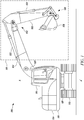
- FIG. 1 illustrates a side view of an exemplary machine 100 equipped with an arm assembly 102, according to an embodiment of the present disclosure.
- the machine 100 may be an excavator, a material handler, a long reach excavator, a foundation drill, a rock drill, a piling machine, a tunneling machine, or a front shovel.
- the machine 100 is shown to be an excavator-type earthmoving or logging machine.
- the arm assembly 102 includes linkages such as a boom 104, at least one arm, such as a first arm 106, and a work tool 108.
- the boom 104 may be pivotally connected to a chassis 110 of the machine 100
- the first arm 106 may be pivotally connected to the boom 104
- the work tool 108 may be pivotally connected to the first arm 106.
- the machine 100 may also include a ground engaging unit 112, such as tracks for propelling the machine 100, a power source 114 to power the arm assembly 102 and the ground engaging unit 112, and an operator cabin 116 for hosting user interface devices for controlling the arm assembly 102 and the ground engaging unit 112.
- the power source 114 may include an engine, such as a diesel engine, a gasoline engine, a gaseous fuel-powered engine, or any other type of combustion engine known in the art.
- the power source 114 may alternatively embody a non-combustion source of power such as a fuel cell, a power storage device, or another source known in the art.
- the power source 114 may produce a mechanical or electrical power output that may then be converted to hydraulic power for moving the arm assembly 102 and the work tool 108.
- an overall movement of the work tool 108 in a first vertical plane 118 may be achieved in three parts, first by raising and lowering the boom 104 with respect to the chassis 110, second by moving the first arm 106 toward and outward with respect to the operator cabin 116, and third by rotating the work tool 108 relative to the first arm 106.
- the boom 104 may be raised and lowered by a pair of first hydraulic actuators 120.
- the first arm 106 may be moved toward and outward with respect to the operator cabin 116 by a second hydraulic actuator 122.
- a third hydraulic actuator 124 may be used to turn the work tool 108 relative to the first arm 106.
- the chassis 110 and the arm assembly 102 may be rotated about a vertical axis A-A' (shown in FIG. 1 ) by a fourth hydraulic actuator 126, such as a hydraulic motor, with respect to the ground engaging unit 112.
- a fourth hydraulic actuator 126 such as a hydraulic motor
- the machine 100 includes a coupling apparatus 128 for coupling the work tool 108 to the arm assembly 102 and to aid in the turning movements of the work tool 108 with respect to the first arm 106.
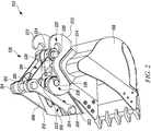
- FIG. 2 illustrates the arm assembly 102 and the coupling apparatus 128 operably coupled to the arm assembly 102, in accordance with an embodiment of the present disclosure.
- the arm assembly 102 includes the first arm 106, which extends longitudinally away from the operator cabin 116.
- the first arm 106 is considered to have a rectangular cross-section, and accordingly the first arm 106 has a first side 202 and a second side (not shown) opposite to the first side 202.
- the arm assembly 102 includes a first connecting arm 204 and a second connecting arm 206.
- the first connecting arm 204 has a first end 208 and a second end 210.
- the first end 208 of the first connecting arm 204 is adapted to be attached to the first side 202 of the first arm 106 and the second end 210 of the first connecting arm 204 is disposed distant from the surface of the first arm 106.
- the second connecting arm 206 has a first end 212 and a second end 214.
- the first end 212 of the second connecting arm 206 is adapted to be attached to the second side of the first arm 106 and the second end 214 of the second connecting arm 206 is disposed distant from the surface of the first arm 106.
- the first connecting arm 204 and the second connecting arm 206 may be positioned inclined with a certain angle with respect to the first arm 106.
- the arm assembly 102 may further include a second arm 216 having a first end 218 and a second end 220.
- the first end 218 of the second arm 216 is attached to the second end 210 of the first connecting arm 204 and the second end 214 of the second connecting arm 206.
- the second end 220 of the second arm 216 is disposed distant from the first end 218; such that the second arm 216 is inclined to the first connecting arm 204 and the second connecting arm 206.
- the first arm 106 may be a stick end of the arm assembly 102
- the second arm 216 may be a push bar.
- the arm assembly 102 includes at least one mounting means, such as a first mounting means 222 and a second mounting means 224.
- the first mounting means 222 is located at the first side 202 of the first arm 106, as shown in FIG. 2 .
- the second mounting means 224 is located at the second end 220 of the second arm 216.
- the first mounting means 222 and the second mounting means 224 may be, for example, includes passageways formed in, for example, hollow cylindrical components.
- the work tool 108 includes at least one tool engagement means, such as a first tool engagement means 226 and a second tool engagement means 227.
- the present embodiment includes a pair of first tool engagement means 226 and a pair of second tool engagement means 227.
- the first tool engagement means 226 and the second tool engagement means 227 are adapted to be coupled to the first mounting means 222 and the second mounting means 224 respectively.
- the first and second tool engagement means 226, 227 may includes recesses located on side plates 232 and 233 respectively.
- each side plate 232, 233 may include a pair of inwardly facing hooks forming the recesses.
- the openings of the recesses forming the first tool engagement means 226 may face the openings of the recesses forming the second tool engagement means 227.
- the side plate 232 and side plate 233 are attached to a base member 234.
- the base member 234 is adapted to be attached to the work tool 108.
- the base member 234 may be welded to the work tool 108.
- the first and second tool engagement means 226, 227 may be formed as an integral part of the work tool 108.
- the tool engagement means 226, 227 may be attached to the work tool 108 in various other ways, as would be known to a person skilled in the art, albeit with few variations to the structure of the first and second tool engagement means 226, 227 and the work tool 108 illustrated in FIG. 2 .
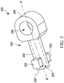
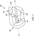
- FIGS. 3-5 illustrate the coupling apparatus 128, according to the embodiment of the present disclosure. Reference may also be made to FIG. 2 to describe one or more components of the work tool 108.
- the coupling apparatus 128 includes an actuator 240.
- the actuator 240 includes a first member 242 and a second member 244. Further, the actuator 240 defines a longitudinal axis B-B' that passes through the center of the first and second member 242, 244, as shown in FIGS. 3 and 4 .
- the first member 242 is circular in cross section. Alternately, the first member 242 can square or rectangle or any other shape according to requirement.
- the first member 242 includes a first end 246 and second end 248 distal, and separated along axis B-B', from the first end 246.
- the first end 246 of the first member 242 is provided with a hole 230.
- the hole 230 is disposed perpendicular to the longitudinal axis B-B' as shown in FIG. 3 .
- the first member 242 includes an outer surface 250 that extends from the first end 246 to the second end 248.
- the outer surface 250 includes one or more stops 252.
- the outer surface 250 disposes a pair of stops 252 proximal to the second end 248.
- the stops 252 are square extrusions. Alternately, there may be multiple stops 252 in any location on the outer surface 252 of circular, rectangular or of any other shape, according to the design requirements.
- Each stop 252 extends radially perpendicular to the outer surface 250 of the first member 242.
- the first member 242 further includes a passageway 254 extending therein from the second end 248 as shown.
- the passageway 254 is disposed such that the longitudinal axis B-B' passes through a center of the passageway 254 as shown.
- the passageway 254 is a circular hole.
- the passageway 254 may be a square, rectangular hole or a hole of any other cross section according to the design requirements.
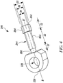
- the second member 244 extends between a first end 256 and a second end 258.
- the second end 258 of the second member 244 is distal to and separated along longitudinal axis B-B' from the first end 256.
- the second member 244 includes an elongate body 245.
- the elongate body 245 is cylindrical and substantially round in cross section. In another, example the elongate body 245 can be square rectangle or any other shape according to the design requirements.
- the elongate body 245 includes a series of different diameters along axis B-B' between the first end 256 and the second end 258.
- the elongate body 245 includes a first portion 260 having uniform diameter, a second portion 262 of a larger uniform diameter connected to the first portion 260 and a third portion 264 of yet a larger uniform diameter connected to the second portion 262.
- the first portion 260 has a diameter D1 about the longitudinal axis B-B' along a length L1 along the longitudinal axis B-B'.
- the second portion 262 has a diameter D2 about the longitudinal axis B-B' and a length L2 in the longitudinal direction axis B-B'.
- the third portion 264 extends between the second portion 262 and the second end 258 with a diameter D3 about the longitudinal axis B-B' and length L3.
- L2 is greater than L3 and L3 is greater than L1, although in alternative embodiments the lengths L1, L2, L3 may be equal or different.
- D3 is greater than D2 and D2 is greater than D1, although in alternative embodiments the diameters D1, D2, D3 may be equal or different.
- the first and second members 242, 244 are coupled together. As illustrated in FIG. 6 , the passageway 254 of the first member 242 slidably receives the second portion 262 and the third portion 264 of the second member 244. The diameter "D3" of the third portion 264 that extends radially from the diameter "D2" of the second portion 262 abuts within a protrusion within the passageway 254. Further, the second member 244 can be relatively displaced along the length L2 of the second portion 262 within the passageway 254. In an example, the relative displacement between the first and second member 242, 244 may be carried out in any way known in the art, such as manually, hydraulically or magnetically.
- the coupling apparatus 128 further includes a locking sleeve 270.
- the locking sleeve 270 is mounted over the actuator 240.
- the locking sleeve 270 includes a first portion 272 and a second portion 274 extending from the first portion 272.
- the first portion includes a home 271 therethrough (illustrated in FIG. 5 ).
- the home 271 receives the first portion 260 of the second member 244, allowing the locking sleeve 270 to turn about the longitudinal axis B-B'.
- the second portion 274 includes one or more protrusions 276 that extend along the longitudinal axis B-B' from the first portion 272.
- the protrusions 276 dispose a pair of first slot 275 and a second slot 278.
- the first slot 275 is configured to receive the stops 252 when the second portion 262 is partially or completely received within the passageway 254.
- the second slot 278 is disposed distal to the first portion 272.
- the second slot 272 is shaped to receive the stops 252 when the second portion 262 extends from the passageway 254.
- the actuator 240 is arranged to move the first and second coupling means 228, 230 between extended and retracted positions as shown in FIG. 2 and FIGS. 8 to 10 by moving the first and second members 242, 244 relative to one another.
- the second portion 262 In an example the retracted position the second portion 262 is partially or completely received within the passageway 254, as shown in FIG. 2 .
- at least one of the holes 228, 230 is disengaged from the first and/or second tool engagement means 226, 227.
- the second portion 262 is partially or completely extends out of the passageway 254.
- the coupling apparatus 128 includes a first coupling means 236 and a second coupling means 238.
- the first coupling means 236 is adapted to engage with the first arm 106 and the first tool engagement means 226.
- the second coupling means 238 is adapted to engage with the second arm 216 and the second tool engagement means 227.
- the first coupling means 236 is a pin member for coupling the first tool engagement means 226 with the hole 228 of the second member 244 and the first mounting means 222 of the first arm 106.
- the second coupling means 238 is a pin member for coupling the second tool engagement means 227 with the second mounting means 224 of the second arm 216 and the hole 230 of the first member 242.
- the first and second coupling means 236, 238 extend outwards from the passageways of the first and second mounting means 222, 224. The first and second coupling means 236, 238 are received within the first and second tool engagement means 226, 227.
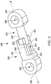
- the first member 242 includes a cylinder and the second member 244 includes a piston that is movable within the cylinder.
- the first and second members 242, 244 may be fluidly coupled to a hydraulic circuit (not shown).
- the hydraulic circuit may be controlled by an operator to retract or extend the first and/or second members 242, 244.
- the hydraulic circuit may supply pressurized hydraulic fluid to the cylinder formed within the first member 242, and may force the piston formed in the second member 244 to extend with respect to the first member 242.
- a restriction to the flow of hydraulic fluid from the cylinder restricts the movement of the first member 242, with respect to the second member 244, thereby locking the actuator 240 in the extended position thereof.
- the present disclosure provides the coupling apparatus 128 for assembling the work tool 108 with the arm assembly 102 of the machine 100.
- the present disclosure further provides a method 1200 for assembling the work tool 108 with the arm assembly 102.
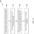
- FIG. 12 illustrates a flowchart of the method, according to an embodiment of the present disclosure.
- the method 1200 may be implemented in any suitable hardware, such that the hardware employed can perform the steps of the method 1200 readily and on a real-time basis. For the convenience in description, various steps of the method 1200 will be described in conjunction with the preceding figures of the present disclosure.
- the first coupling means 236 is engaged with the first arm 106 of the arm assembly 102 and first tool engagement means 226.
- the actuator 240 is in a retracted position.
- the first coupling means 236 is aligned with the first mounting means 222.
- the first coupling means 236 is received within first coupling means 236 and the first mounting means 222.
- the extended portions of the first coupling means 236 are coupled with the first tool engagement means 226, particularly by being received in the recesses as shown in FIG. 8 .
- the second coupling means 238 is engaged with the second arm 216.
- the second coupling means 238 is aligned with the second mounting means 224.
- the second coupling means 238 is received within the second mounting means 224 as shown in FIG. 9 .
- the actuator 240 is moved to an extended position to engage the second coupling means 238 to the second tool engagement means 227.
- the first member 242 of the actuator 240 is moved relative to the second member 244 along the longitudinal axis B-B' to move into an extended position.
- the second coupling means 238 extends further to couple the extended portion of the second coupling means 238 to the second tool engagement means 228, particularly by being received within the recesses.
- the locking sleeve 270 is moved to a locked position.
- the locking sleeve 270 is turned about the abutment portion 260 such that the second portion 274 conforms to the stop 252 of the first member 242 as shown in FIG. 10 .
- the locking sleeve 270 prevents any relative motion such as retraction between the first member 242 and the second member 244 thereby coupling the work tool 108 to the machine 100.
- In the locked position one or more protrusions 276 of the locking sleeve 270 engages with the stop 252 of the first member 242.
- the locking sleeve 270 and the stop 252 are arranged such that the motion of the locking sleeve 270 is prevented in at least one direction.
- the locking sleeve 270 may be spring loaded such that the locking sleeve 270 turns to the locked position when the first and second members 242, 244 are at extended position.
- the locking sleeve 270 may have a different mechanism to lock the actuator 240 such as push, slide, latch and the like.
- the coupling apparatus 128 of the present disclosure provides an easy and efficient coupling of the work tool 108 to the arm assembly 102. Since the coupling or the assembling of the work tool 108 and the arm assembly 102 is assisted by the actuator 240 and the locking sleeve 270, the process of coupling can be performed in short duration of time. Further, owing to the presence of flexibility in placing the first and second tool engagement means 226, 227, the coupling apparatus 128 can be replaced or coupled to the arm assembly 102 at any instant of time.
Abstract
Description
- The present disclosure relates to engaging work tools to machines, and more particularly it relates to an apparatus and a method for assembling a work tool to an arm assembly of a machine.
- Machines, such as, hydraulic excavators, hydraulic shovels, backhoe loaders and the like, are often required to perform different kinds of work on a work site. Therefore, different work tools, such as buckets, hammers, rippers, and grapples, may have to be engaged with an arm assembly (including for example, sticks and booms) of the machine. It is known that the process of removing one work tool from the arm assembly and replacing the work tool with a different work tool may be a time consuming and difficult process. Quick couplers have been employed to enable quick engagement of the stick and the work tool and the quick couplers do, to an extent, reduce effort required for removing the work tool and replacing it. However, such quick couplers add weight to the stick end and build up the stick height/length. As a result, the machine's capabilities may be compromised.
- For example,
US Patent 5,400,531 A discloses an excavator or earth-working device. The earth working device includes a forked dipper arm, a linkage and an earth-working implement pivotally connected to the forked dipper arm and linkage. The implement is attached to a dipper arm and linkage of the earth-working device by a so-called "quick-hitch" connection to allow interchange between various earth-working implements. A safety device may also be provided on the "quick-hitch" connection to prevent accidental detachment of the implement from the dipper arm and linkage. - The present disclosure provides an apparatus for coupling a work tool to an arm assembly of a machine. The work tool includes first and second tool engagement means and the arm assembly includes first and second arms. Further, the apparatus includes a first coupling means adapted to engage with the first arm and the first tool engagement means. The apparatus further includes a second coupling means adapted to engage with the second arm and the second tool engagement means. The apparatus also includes an actuator coupled to and arranged to move the first and second coupling means between a retracted position, in which the first and/or second coupling means is disengaged from the first and/or second tool engagement means, and an extended position, in which the first and second coupling means are engaged with the first and second tool engagement means. Further, a locking sleeve is mounted at least partially around the actuator, the locking sleeve being moveable into a locked position to prevent the first and second coupling means from moving into the retracted position from the extended position.
- The present disclosure further provides a machine comprising the aforementioned apparatus. In a further embodiment, the present disclosure may further provide an arrangement comprising aforementioned apparatus, arm assembly and work tool.
- The present disclosure further provides a method of coupling a work tool to an arm assembly of a machine. The work tool having first and second tool engagement means and the arm assembly having first and second arms. The method includes engaging a first coupling means with the first arm and the first tool engagement means. The method includes engaging a second coupling means with the second arm. The method further includes moving an actuator to an extended position to engage the second coupling means to the second tool engagement means. The method also includes moving a locking sleeve to a locked position to prevent the first and second coupling means from moving into the retracted position from the extended position.
- Other features and aspects of this disclosure will be apparent from the following description and the accompanying drawings.
-
-
FIG. 1 illustrates a side view of a machine equipped with an arm assembly, according to an embodiment of the present disclosure; -
FIG. 2 illustrates the arm assembly equipped with a coupling apparatus for assembling a work tool to the arm assembly in a retracted position, according to an embodiment of the present disclosure; -
FIG. 3 illustrates a coupling apparatus, according to an embodiment of the present disclosure; -
FIG. 4 illustrates the coupling apparatus, according to an embodiment of the present disclosure; -
FIG. 5 illustrates a locking sleeve of the coupling apparatus, according to an embodiment of the present disclosure; -
FIG. 6 illustrates a locking sleeve disposed over an actuator, according to an embodiment of the present disclosure; -
FIG. 7 illustrates a cross sectional view of the locking sleeve disposed over an actuator; -
FIG. 8 illustrates an operation to couple or assemble the tool engagement means and the arm assembly, according to an embodiment of the present disclosure; -
FIG. 9 illustrates an operation to couple or assemble the tool engagement means and the arm assembly, according to an embodiment of the present disclosure; -
FIG. 10 illustrates an operation to couple or assemble the tool engagement means and the arm assembly, according to an embodiment of the present disclosure; -
FIG. 11 illustrates the arm assembly equipped with an apparatus for assembling a work tool to the arm assembly, according to an embodiment of the present disclosure; and -
FIG. 12 is a flowchart of a method of assembling the tool engagement to the arm assembly, according to an embodiment of the present disclosure. - Reference will now be made in detail to specific embodiments or features, examples of which are illustrated in the accompanying drawings. Wherever possible, corresponding or similar reference numbers will be used throughout the drawings to refer to the same or corresponding parts. Moreover, references to various elements described herein, are made collectively or individually when there may be more than one element of the same type. However, such references are merely exemplary in nature. It may be noted that any reference to elements in the singular may also be construed to relate to the plural and vice-versa without limiting the scope of the disclosure to the exact number or type of such elements unless set forth explicitly in the appended claims.
-
FIG. 1 illustrates a side view of anexemplary machine 100 equipped with anarm assembly 102, according to an embodiment of the present disclosure. Themachine 100 may be an excavator, a material handler, a long reach excavator, a foundation drill, a rock drill, a piling machine, a tunneling machine, or a front shovel. In the illustrated embodiment, themachine 100 is shown to be an excavator-type earthmoving or logging machine. Further, thearm assembly 102 includes linkages such as aboom 104, at least one arm, such as afirst arm 106, and awork tool 108. Theboom 104 may be pivotally connected to achassis 110 of themachine 100, thefirst arm 106 may be pivotally connected to theboom 104, and thework tool 108 may be pivotally connected to thefirst arm 106. - The
machine 100 may also include a groundengaging unit 112, such as tracks for propelling themachine 100, apower source 114 to power thearm assembly 102 and theground engaging unit 112, and anoperator cabin 116 for hosting user interface devices for controlling thearm assembly 102 and theground engaging unit 112. Thepower source 114 may include an engine, such as a diesel engine, a gasoline engine, a gaseous fuel-powered engine, or any other type of combustion engine known in the art. Thepower source 114 may alternatively embody a non-combustion source of power such as a fuel cell, a power storage device, or another source known in the art. Thepower source 114 may produce a mechanical or electrical power output that may then be converted to hydraulic power for moving thearm assembly 102 and thework tool 108. - Further, an overall movement of the
work tool 108 in a first vertical plane 118 (shown inFIG. 1 ) may be achieved in three parts, first by raising and lowering theboom 104 with respect to thechassis 110, second by moving thefirst arm 106 toward and outward with respect to theoperator cabin 116, and third by rotating thework tool 108 relative to thefirst arm 106. Theboom 104 may be raised and lowered by a pair of firsthydraulic actuators 120. Thefirst arm 106 may be moved toward and outward with respect to theoperator cabin 116 by a secondhydraulic actuator 122. In addition, a thirdhydraulic actuator 124 may be used to turn thework tool 108 relative to thefirst arm 106. Furthermore, thechassis 110 and thearm assembly 102 may be rotated about a vertical axis A-A' (shown inFIG. 1 ) by a fourthhydraulic actuator 126, such as a hydraulic motor, with respect to the groundengaging unit 112. According to an aspect of the present disclosure, themachine 100 includes acoupling apparatus 128 for coupling thework tool 108 to thearm assembly 102 and to aid in the turning movements of thework tool 108 with respect to thefirst arm 106. -
FIG. 2 illustrates thearm assembly 102 and thecoupling apparatus 128 operably coupled to thearm assembly 102, in accordance with an embodiment of the present disclosure. As described earlier, thearm assembly 102 includes thefirst arm 106, which extends longitudinally away from theoperator cabin 116. In one example and for the purpose of this description, thefirst arm 106 is considered to have a rectangular cross-section, and accordingly thefirst arm 106 has afirst side 202 and a second side (not shown) opposite to thefirst side 202. Further, thearm assembly 102 includes a first connectingarm 204 and a second connectingarm 206. The first connectingarm 204 has afirst end 208 and asecond end 210. Thefirst end 208 of the first connectingarm 204 is adapted to be attached to thefirst side 202 of thefirst arm 106 and thesecond end 210 of the first connectingarm 204 is disposed distant from the surface of thefirst arm 106. Similarly, the second connectingarm 206 has afirst end 212 and asecond end 214. Thefirst end 212 of the second connectingarm 206 is adapted to be attached to the second side of thefirst arm 106 and thesecond end 214 of the second connectingarm 206 is disposed distant from the surface of thefirst arm 106. In one example, the first connectingarm 204 and the second connectingarm 206 may be positioned inclined with a certain angle with respect to thefirst arm 106. - The
arm assembly 102 may further include asecond arm 216 having afirst end 218 and asecond end 220. Thefirst end 218 of thesecond arm 216 is attached to thesecond end 210 of the first connectingarm 204 and thesecond end 214 of the second connectingarm 206. Further, thesecond end 220 of thesecond arm 216 is disposed distant from thefirst end 218; such that thesecond arm 216 is inclined to the first connectingarm 204 and the second connectingarm 206. In an embodiment of the present disclosure, thefirst arm 106 may be a stick end of thearm assembly 102, and thesecond arm 216 may be a push bar. - For the purpose of coupling the
coupling apparatus 128 to thearm assembly 102, thearm assembly 102 includes at least one mounting means, such as a first mounting means 222 and a second mounting means 224. In said implementation, the first mounting means 222 is located at thefirst side 202 of thefirst arm 106, as shown inFIG. 2 . The second mounting means 224 is located at thesecond end 220 of thesecond arm 216. The first mounting means 222 and the second mounting means 224 may be, for example, includes passageways formed in, for example, hollow cylindrical components. - In construction, as illustrated in
FIG. 2 , thework tool 108 includes at least one tool engagement means, such as a first tool engagement means 226 and a second tool engagement means 227. The present embodiment includes a pair of first tool engagement means 226 and a pair of second tool engagement means 227. The first tool engagement means 226 and the second tool engagement means 227 are adapted to be coupled to the first mounting means 222 and the second mounting means 224 respectively. The first and second tool engagement means 226, 227 may includes recesses located onside plates side plate side plate 232 andside plate 233 are attached to abase member 234. Further, thebase member 234 is adapted to be attached to thework tool 108. In one example, thebase member 234 may be welded to thework tool 108. In another example, the first and second tool engagement means 226, 227 may be formed as an integral part of thework tool 108. However, the tool engagement means 226, 227 may be attached to thework tool 108 in various other ways, as would be known to a person skilled in the art, albeit with few variations to the structure of the first and second tool engagement means 226, 227 and thework tool 108 illustrated inFIG. 2 . -
FIGS. 3-5 illustrate thecoupling apparatus 128, according to the embodiment of the present disclosure. Reference may also be made toFIG. 2 to describe one or more components of thework tool 108. Thecoupling apparatus 128 includes anactuator 240. Theactuator 240 includes afirst member 242 and asecond member 244. Further, theactuator 240 defines a longitudinal axis B-B' that passes through the center of the first andsecond member FIGS. 3 and4 . In the present embodiment, thefirst member 242 is circular in cross section. Alternately, thefirst member 242 can square or rectangle or any other shape according to requirement. Thefirst member 242 includes afirst end 246 andsecond end 248 distal, and separated along axis B-B', from thefirst end 246. Thefirst end 246 of thefirst member 242 is provided with ahole 230. Thehole 230 is disposed perpendicular to the longitudinal axis B-B' as shown inFIG. 3 . - The
first member 242 includes anouter surface 250 that extends from thefirst end 246 to thesecond end 248. Theouter surface 250 includes one or more stops 252. In the present example, theouter surface 250 disposes a pair ofstops 252 proximal to thesecond end 248. Also, thestops 252 are square extrusions. Alternately, there may bemultiple stops 252 in any location on theouter surface 252 of circular, rectangular or of any other shape, according to the design requirements. Eachstop 252 extends radially perpendicular to theouter surface 250 of thefirst member 242. Thefirst member 242 further includes apassageway 254 extending therein from thesecond end 248 as shown. Thepassageway 254 is disposed such that the longitudinal axis B-B' passes through a center of thepassageway 254 as shown. In the present disclosure, thepassageway 254 is a circular hole. Alternately, thepassageway 254 may be a square, rectangular hole or a hole of any other cross section according to the design requirements. - As best shown in
FIG. 4 , thesecond member 244 extends between afirst end 256 and asecond end 258. Thesecond end 258 of thesecond member 244 is distal to and separated along longitudinal axis B-B' from thefirst end 256. In the present embodiment, thesecond member 244 includes an elongate body 245. In an example the elongate body 245 is cylindrical and substantially round in cross section. In another, example the elongate body 245 can be square rectangle or any other shape according to the design requirements. The elongate body 245 includes a series of different diameters along axis B-B' between thefirst end 256 and thesecond end 258. The elongate body 245 includes afirst portion 260 having uniform diameter, asecond portion 262 of a larger uniform diameter connected to thefirst portion 260 and athird portion 264 of yet a larger uniform diameter connected to thesecond portion 262. - In particular, the
first portion 260 has a diameter D1 about the longitudinal axis B-B' along a length L1 along the longitudinal axis B-B'. Thesecond portion 262 has a diameter D2 about the longitudinal axis B-B' and a length L2 in the longitudinal direction axis B-B'. Thethird portion 264 extends between thesecond portion 262 and thesecond end 258 with a diameter D3 about the longitudinal axis B-B' and length L3. In the illustrated embodiment L2 is greater than L3 and L3 is greater than L1, although in alternative embodiments the lengths L1, L2, L3 may be equal or different. In the illustrated embodiment D3 is greater than D2 and D2 is greater than D1, although in alternative embodiments the diameters D1, D2, D3 may be equal or different. - The first and
second members FIG. 6 , thepassageway 254 of thefirst member 242 slidably receives thesecond portion 262 and thethird portion 264 of thesecond member 244. The diameter "D3" of thethird portion 264 that extends radially from the diameter "D2" of thesecond portion 262 abuts within a protrusion within thepassageway 254. Further, thesecond member 244 can be relatively displaced along the length L2 of thesecond portion 262 within thepassageway 254. In an example, the relative displacement between the first andsecond member - Referring to
FIG. 5 to 10 , thecoupling apparatus 128 further includes a lockingsleeve 270. The lockingsleeve 270 is mounted over theactuator 240. The lockingsleeve 270 includes afirst portion 272 and asecond portion 274 extending from thefirst portion 272. The first portion includes ahome 271 therethrough (illustrated inFIG. 5 ). Thehome 271 receives thefirst portion 260 of thesecond member 244, allowing the lockingsleeve 270 to turn about the longitudinal axis B-B'. Thesecond portion 274 includes one ormore protrusions 276 that extend along the longitudinal axis B-B' from thefirst portion 272. In the present embodiment, theprotrusions 276 dispose a pair offirst slot 275 and asecond slot 278. Thefirst slot 275 is configured to receive thestops 252 when thesecond portion 262 is partially or completely received within thepassageway 254. Thesecond slot 278 is disposed distal to thefirst portion 272. Thesecond slot 272 is shaped to receive thestops 252 when thesecond portion 262 extends from thepassageway 254. - The
actuator 240 is arranged to move the first and second coupling means 228, 230 between extended and retracted positions as shown inFIG. 2 andFIGS. 8 to 10 by moving the first andsecond members second portion 262 is partially or completely received within thepassageway 254, as shown inFIG. 2 . In the retracted position, at least one of theholes second portion 262 is partially or completely extends out of thepassageway 254. - The
coupling apparatus 128 includes a first coupling means 236 and a second coupling means 238. The first coupling means 236 is adapted to engage with thefirst arm 106 and the first tool engagement means 226. The second coupling means 238 is adapted to engage with thesecond arm 216 and the second tool engagement means 227. In the present disclosure, the first coupling means 236 is a pin member for coupling the first tool engagement means 226 with thehole 228 of thesecond member 244 and the first mounting means 222 of thefirst arm 106. The second coupling means 238 is a pin member for coupling the second tool engagement means 227 with the second mounting means 224 of thesecond arm 216 and thehole 230 of thefirst member 242. In the present embodiment the first and second coupling means 236, 238 extend outwards from the passageways of the first and second mounting means 222, 224. The first and second coupling means 236, 238 are received within the first and second tool engagement means 226, 227. - Referring to
FIG. 11 , thefirst member 242 includes a cylinder and thesecond member 244 includes a piston that is movable within the cylinder. Further, the first andsecond members second members first member 242, and may force the piston formed in thesecond member 244 to extend with respect to thefirst member 242. Further, a restriction to the flow of hydraulic fluid from the cylinder restricts the movement of thefirst member 242, with respect to thesecond member 244, thereby locking theactuator 240 in the extended position thereof. - The present disclosure provides the
coupling apparatus 128 for assembling thework tool 108 with thearm assembly 102 of themachine 100. The present disclosure further provides amethod 1200 for assembling thework tool 108 with thearm assembly 102.FIG. 12 illustrates a flowchart of the method, according to an embodiment of the present disclosure. Further, themethod 1200 may be implemented in any suitable hardware, such that the hardware employed can perform the steps of themethod 1200 readily and on a real-time basis. For the convenience in description, various steps of themethod 1200 will be described in conjunction with the preceding figures of the present disclosure. - Referring to
FIG. 12 , atstep 1202 of themethod 1200, the first coupling means 236 is engaged with thefirst arm 106 of thearm assembly 102 and first tool engagement means 226. In one example, theactuator 240 is in a retracted position. The first coupling means 236 is aligned with the first mounting means 222. The first coupling means 236 is received within first coupling means 236 and the first mounting means 222. Further, the extended portions of the first coupling means 236 are coupled with the first tool engagement means 226, particularly by being received in the recesses as shown inFIG. 8 . Atstep 1204 the second coupling means 238 is engaged with thesecond arm 216. The second coupling means 238 is aligned with the second mounting means 224. The second coupling means 238 is received within the second mounting means 224 as shown inFIG. 9 . - At
step 1206 theactuator 240 is moved to an extended position to engage the second coupling means 238 to the second tool engagement means 227. Thefirst member 242 of theactuator 240 is moved relative to thesecond member 244 along the longitudinal axis B-B' to move into an extended position. The second coupling means 238 extends further to couple the extended portion of the second coupling means 238 to the second tool engagement means 228, particularly by being received within the recesses. - At
step 1208, the lockingsleeve 270 is moved to a locked position. The lockingsleeve 270 is turned about theabutment portion 260 such that thesecond portion 274 conforms to thestop 252 of thefirst member 242 as shown inFIG. 10 . The lockingsleeve 270 prevents any relative motion such as retraction between thefirst member 242 and thesecond member 244 thereby coupling thework tool 108 to themachine 100. In the locked position one ormore protrusions 276 of the lockingsleeve 270 engages with thestop 252 of thefirst member 242. Further, the lockingsleeve 270 and thestop 252 are arranged such that the motion of the lockingsleeve 270 is prevented in at least one direction. In an unlocked position theprotrusions 276 allows relative motion between the first and thesecond member sleeve 270 may be spring loaded such that the lockingsleeve 270 turns to the locked position when the first andsecond members sleeve 270 may have a different mechanism to lock theactuator 240 such as push, slide, latch and the like. - Therefore, as it would be understood to the person skilled in the art, the
coupling apparatus 128 of the present disclosure provides an easy and efficient coupling of thework tool 108 to thearm assembly 102. Since the coupling or the assembling of thework tool 108 and thearm assembly 102 is assisted by theactuator 240 and the lockingsleeve 270, the process of coupling can be performed in short duration of time. Further, owing to the presence of flexibility in placing the first and second tool engagement means 226, 227, thecoupling apparatus 128 can be replaced or coupled to thearm assembly 102 at any instant of time. Furthermore, since the coupling or the assembling of thework tool 108 and thearm assembly 102 may be carried out by theactuator 240 and lockingsleeve 270, provided at thearm assembly 102, overall weight and length of thearm assembly 102 remains substantially same, and therefore capabilities of themachine 100 remain uncompromised. - While aspects of the present disclosure have been particularly shown and described with reference to the embodiments above, it will be understood by those skilled in the art that various additional embodiments may be contemplated by the modification of the disclosed machines, systems and methods without departing from the spirit and scope of what is disclosed. Such embodiments should be understood to fall within the scope of the present disclosure as determined based upon the claims and any equivalents thereof.
Claims (13)
- An apparatus for coupling a work tool to an arm assembly of a machine, the work tool comprising first and second tool engagement means and the arm assembly comprising first and second arms, wherein the apparatus comprises:a first coupling means adapted to engage with the first arm and the first tool engagement means;a second coupling means adapted to engage with the second arm and the second tool engagement means; andan actuator coupled to and arranged to move the first and second coupling means between a retracted position, in which the first and/or second coupling means is disengaged from the first and/or second tool engagement means, and an extended position, in which the first and second coupling means are engaged with the first and second tool engagement means,wherein a locking sleeve is mounted at least partially around the actuator, the locking sleeve being moveable into a locked position to prevent the first and second coupling means from moving into the retracted position from the extended position.
- An apparatus as claimed in claim 1, wherein the first and second coupling means comprise first and second pin members respectively.
- The apparatus of claim 2, wherein the actuator comprises a first member moveable relative to a second member, the locking sleeve being mounted at least partially around the first and/or second member.
- The apparatus as claimed in claim 3, wherein the first member comprises a stop against which the locking sleeve abuts when in the locked position.
- The apparatus as claimed in claim 3 or claim 4, wherein the second member comprises an abutment portion against which the locking sleeve abuts.
- The apparatus as claimed in claim 4 or claim 5 wherein the locking sleeve and stop are arranged such that, when in the locked position, rotation of the locking sleeve is prevented in at least one direction.
- The apparatus as claimed in any one of claims 3 to 6 wherein the first member comprises a cylinder and the second member comprises a piston moveable within the cylinder.
- The apparatus as claimed in any one of the preceding claims, wherein the locking sleeve includes:a first portion adapted to abut an abutment portion of the actuator; anda second portion extending from the first portion, wherein the second portion includes one or more protrusions extending along the longitudinal axis of the locking sleeve, andwherein the locking sleeve is adapted to rotate about the longitudinal axis between a locked position and an unlocked position.
- The apparatus as claimed in any one of claims 4 to 8, wherein the one or more protrusions of the second portion of the locking sleeve engages with the stop of the actuator when the locking sleeve is in the locked position.
- A machine comprising the apparatus of any one of the preceding claims.
- A method of coupling a work tool to an arm assembly of a machine, the work tool having first and second tool engagement means and the arm assembly having first and second arms, the method comprising:engaging a first coupling means with the first arm and the first tool engagement means;engaging a second coupling means with the second arm;moving an actuator to an extended position to engage the second coupling means to the second tool engagement means; and,moving a locking sleeve to a locked position to prevent the first and second coupling means from moving into the retracted position from the extended position.
- The method of claim 10, wherein the step of moving the actuator includes moving a first member of the actuator relative to a second member of actuator.
- The method of claim 10, wherein the step of moving the locking sleeve includes rotating the locking sleeve around the actuator to abut against the abutment portion of the second member.
Applications Claiming Priority (1)
| Application Number | Priority Date | Filing Date | Title |
|---|---|---|---|
| GB1520735.0A GB2544747A (en) | 2015-11-24 | 2015-11-24 | Apparatus and method for coupling work tool to a machine |
Publications (2)
| Publication Number | Publication Date |
|---|---|
| EP3173535A1 true EP3173535A1 (en) | 2017-05-31 |
| EP3173535B1 EP3173535B1 (en) | 2021-09-08 |
Family
ID=55133301
Family Applications (1)
| Application Number | Title | Priority Date | Filing Date |
|---|---|---|---|
| EP16199585.7A Active EP3173535B1 (en) | 2015-11-24 | 2016-11-18 | Apparatus and method for coupling work tool to a machine |
Country Status (4)
| Country | Link |
|---|---|
| US (1) | US20170145653A1 (en) |
| EP (1) | EP3173535B1 (en) |
| CN (1) | CN106881584B (en) |
| GB (1) | GB2544747A (en) |
Families Citing this family (3)
| Publication number | Priority date | Publication date | Assignee | Title |
|---|---|---|---|---|
| US10978262B2 (en) * | 2017-10-20 | 2021-04-13 | Otis Elevator Company | Reach tool for use in low voltage applications |
| CN108487359B (en) * | 2018-03-30 | 2021-05-04 | 广东知识城运营服务有限公司 | Head changing device for loader |
| CN112359891B (en) * | 2020-11-17 | 2022-11-18 | 徐州徐工挖掘机械有限公司 | Work device and construction machine |
Citations (6)
| Publication number | Priority date | Publication date | Assignee | Title |
|---|---|---|---|---|
| US5400531A (en) * | 1992-08-20 | 1995-03-28 | Brown; Hilton T. | Excavator device |
| US5607251A (en) * | 1996-04-03 | 1997-03-04 | The Stanley Works | Quick coupler assembly for hanging attachment |
| EP1318242A2 (en) * | 2001-12-06 | 2003-06-11 | Geith Patents Limited | A coupler for coupling an accessory to a dipper arm and a control system for such a coupler |
| US20030133779A1 (en) * | 2002-01-17 | 2003-07-17 | Ashley Heiple | Adapter assembly for an implement coupling system |
| US20040245002A1 (en) * | 2003-06-06 | 2004-12-09 | Shingo Muroto | Screw-rod locking structure for attachment fixture |
| US20050169703A1 (en) * | 2001-11-29 | 2005-08-04 | Jrb Attachments, Llc | Spread-style coupler with supplemental lock system |
Family Cites Families (10)
| Publication number | Priority date | Publication date | Assignee | Title |
|---|---|---|---|---|
| US3469870A (en) * | 1967-11-24 | 1969-09-30 | Homer A Barkus | Telescopic structure with rotatable shaft |
| GB8500911D0 (en) * | 1985-01-15 | 1985-02-20 | Mason S T | Quick-change fitting |
| DE4109783C2 (en) * | 1990-03-23 | 1998-04-09 | Hilton S Enterprises Inc Pty L | Quick coupling device for a device for carrying out earth movements |
| US5597283A (en) * | 1991-04-09 | 1997-01-28 | Jones; Gordon | Quick coupling for heavy equipment attachment |
| EP1210482A1 (en) * | 1999-07-12 | 2002-06-05 | JRB Company, Inc. | Excavator arm assembly with integral quick coupler |
| US6658770B2 (en) * | 2002-01-11 | 2003-12-09 | Rockland, Inc. | Implement coupling assembly for excavating machines and the like |
| CN201473987U (en) * | 2009-07-03 | 2010-05-19 | 厦门厦工小型机械有限公司 | Quick-change frame of excavating working device |
| CN201973001U (en) * | 2011-04-14 | 2011-09-14 | 天津优瑞纳斯液压机械有限公司 | Locking device for piston rod of hydraulic cylinder |
| CN204553448U (en) * | 2015-01-26 | 2015-08-12 | 浙江理工大学 | A kind of pipe fitting quick-mounting device and adopt the fast-assembling wardrobe of this device |
| CN104712623A (en) * | 2015-01-26 | 2015-06-17 | 苏州艾利欧电器有限公司 | Retractable device |
-
2015
- 2015-11-24 GB GB1520735.0A patent/GB2544747A/en not_active Withdrawn
-
2016
- 2016-11-15 US US15/352,119 patent/US20170145653A1/en not_active Abandoned
- 2016-11-18 EP EP16199585.7A patent/EP3173535B1/en active Active
- 2016-11-24 CN CN201611050914.4A patent/CN106881584B/en active Active
Patent Citations (6)
| Publication number | Priority date | Publication date | Assignee | Title |
|---|---|---|---|---|
| US5400531A (en) * | 1992-08-20 | 1995-03-28 | Brown; Hilton T. | Excavator device |
| US5607251A (en) * | 1996-04-03 | 1997-03-04 | The Stanley Works | Quick coupler assembly for hanging attachment |
| US20050169703A1 (en) * | 2001-11-29 | 2005-08-04 | Jrb Attachments, Llc | Spread-style coupler with supplemental lock system |
| EP1318242A2 (en) * | 2001-12-06 | 2003-06-11 | Geith Patents Limited | A coupler for coupling an accessory to a dipper arm and a control system for such a coupler |
| US20030133779A1 (en) * | 2002-01-17 | 2003-07-17 | Ashley Heiple | Adapter assembly for an implement coupling system |
| US20040245002A1 (en) * | 2003-06-06 | 2004-12-09 | Shingo Muroto | Screw-rod locking structure for attachment fixture |
Also Published As
| Publication number | Publication date |
|---|---|
| GB2544747A (en) | 2017-05-31 |
| CN106881584B (en) | 2021-06-04 |
| US20170145653A1 (en) | 2017-05-25 |
| GB201520735D0 (en) | 2016-01-06 |
| EP3173535B1 (en) | 2021-09-08 |
| CN106881584A (en) | 2017-06-23 |
Similar Documents
| Publication | Publication Date | Title |
|---|---|---|
| EP3176331B1 (en) | Apparatus and method for assembling work tool to a machine | |
| US9228314B2 (en) | Quick coupler hydraulic control system | |
| EP3241949B1 (en) | Integrated excavator pin grabber quick coupler | |
| US8281506B2 (en) | Tool coupler assembly | |
| EP3173535B1 (en) | Apparatus and method for coupling work tool to a machine | |
| US20140317967A1 (en) | Excavator with Expanded Work Implement Compatibility | |
| EP2230435A1 (en) | Extendable fluid coupler | |
| US20160251820A1 (en) | Work tool assembly and coupler | |
| US11208785B2 (en) | Tool coupling arrangement having zero offset | |
| US9976277B2 (en) | Apparatus and method for coupling work tool to a machine | |
| KR20170056972A (en) | bucket for excavator | |
| US20140230587A1 (en) | Thumb Assembly | |
| US20150197914A1 (en) | Bucket linkage assembly with lifting eye | |
| US20170121934A1 (en) | Accessory for excavation of a ditch and related methods | |
| KR102616192B1 (en) | Quick coupler for excavator with multi safety apparatus | |
| CN212153490U (en) | Bucket rod of excavator, working arm of excavator and excavator | |
| CN220286156U (en) | Locking mechanism and working machine | |
| WO2004016863A1 (en) | A connector | |
| US20070028488A1 (en) | Bracket and Method for Transport of Articulated Arm Attachment | |
| US20210002849A1 (en) | Drill Adaptor | |
| JP2006097348A (en) | Work tool installing device | |
| KR20180110428A (en) | A Separable Claw for Excavators | |
| KR20140030640A (en) | Attachment mounting device of construction machine |
Legal Events
| Date | Code | Title | Description |
|---|---|---|---|
| PUAI | Public reference made under article 153(3) epc to a published international application that has entered the european phase |
Free format text: ORIGINAL CODE: 0009012 |
|
| STAA | Information on the status of an ep patent application or granted ep patent |
Free format text: STATUS: REQUEST FOR EXAMINATION WAS MADE |
|
| 17P | Request for examination filed |
Effective date: 20161118 |
|
| AK | Designated contracting states |
Kind code of ref document: A1 Designated state(s): AL AT BE BG CH CY CZ DE DK EE ES FI FR GB GR HR HU IE IS IT LI LT LU LV MC MK MT NL NO PL PT RO RS SE SI SK SM TR |
|
| AX | Request for extension of the european patent |
Extension state: BA ME |
|
| STAA | Information on the status of an ep patent application or granted ep patent |
Free format text: STATUS: EXAMINATION IS IN PROGRESS |
|
| 17Q | First examination report despatched |
Effective date: 20190730 |
|
| STAA | Information on the status of an ep patent application or granted ep patent |
Free format text: STATUS: EXAMINATION IS IN PROGRESS |
|
| GRAP | Despatch of communication of intention to grant a patent |
Free format text: ORIGINAL CODE: EPIDOSNIGR1 |
|
| STAA | Information on the status of an ep patent application or granted ep patent |
Free format text: STATUS: GRANT OF PATENT IS INTENDED |
|
| INTG | Intention to grant announced |
Effective date: 20210407 |
|
| GRAS | Grant fee paid |
Free format text: ORIGINAL CODE: EPIDOSNIGR3 |
|
| GRAA | (expected) grant |
Free format text: ORIGINAL CODE: 0009210 |
|
| STAA | Information on the status of an ep patent application or granted ep patent |
Free format text: STATUS: THE PATENT HAS BEEN GRANTED |
|
| AK | Designated contracting states |
Kind code of ref document: B1 Designated state(s): AL AT BE BG CH CY CZ DE DK EE ES FI FR GB GR HR HU IE IS IT LI LT LU LV MC MK MT NL NO PL PT RO RS SE SI SK SM TR |
|
| REG | Reference to a national code |
Ref country code: GB Ref legal event code: FG4D |
|
| REG | Reference to a national code |
Ref country code: AT Ref legal event code: REF Ref document number: 1428718 Country of ref document: AT Kind code of ref document: T Effective date: 20210915 Ref country code: CH Ref legal event code: EP |
|
| REG | Reference to a national code |
Ref country code: IE Ref legal event code: FG4D |
|
| REG | Reference to a national code |
Ref country code: DE Ref legal event code: R096 Ref document number: 602016063382 Country of ref document: DE |
|
| REG | Reference to a national code |
Ref country code: NL Ref legal event code: FP |
|
| REG | Reference to a national code |
Ref country code: SE Ref legal event code: TRGR |
|
| REG | Reference to a national code |
Ref country code: LT Ref legal event code: MG9D |
|
| PG25 | Lapsed in a contracting state [announced via postgrant information from national office to epo] |
Ref country code: LT Free format text: LAPSE BECAUSE OF FAILURE TO SUBMIT A TRANSLATION OF THE DESCRIPTION OR TO PAY THE FEE WITHIN THE PRESCRIBED TIME-LIMIT Effective date: 20210908 Ref country code: BG Free format text: LAPSE BECAUSE OF FAILURE TO SUBMIT A TRANSLATION OF THE DESCRIPTION OR TO PAY THE FEE WITHIN THE PRESCRIBED TIME-LIMIT Effective date: 20211208 Ref country code: FI Free format text: LAPSE BECAUSE OF FAILURE TO SUBMIT A TRANSLATION OF THE DESCRIPTION OR TO PAY THE FEE WITHIN THE PRESCRIBED TIME-LIMIT Effective date: 20210908 Ref country code: ES Free format text: LAPSE BECAUSE OF FAILURE TO SUBMIT A TRANSLATION OF THE DESCRIPTION OR TO PAY THE FEE WITHIN THE PRESCRIBED TIME-LIMIT Effective date: 20210908 Ref country code: HR Free format text: LAPSE BECAUSE OF FAILURE TO SUBMIT A TRANSLATION OF THE DESCRIPTION OR TO PAY THE FEE WITHIN THE PRESCRIBED TIME-LIMIT Effective date: 20210908 Ref country code: RS Free format text: LAPSE BECAUSE OF FAILURE TO SUBMIT A TRANSLATION OF THE DESCRIPTION OR TO PAY THE FEE WITHIN THE PRESCRIBED TIME-LIMIT Effective date: 20210908 |
|
| REG | Reference to a national code |
Ref country code: NO Ref legal event code: T2 Effective date: 20210908 |
|
| REG | Reference to a national code |
Ref country code: AT Ref legal event code: MK05 Ref document number: 1428718 Country of ref document: AT Kind code of ref document: T Effective date: 20210908 |
|
| PG25 | Lapsed in a contracting state [announced via postgrant information from national office to epo] |
Ref country code: LV Free format text: LAPSE BECAUSE OF FAILURE TO SUBMIT A TRANSLATION OF THE DESCRIPTION OR TO PAY THE FEE WITHIN THE PRESCRIBED TIME-LIMIT Effective date: 20210908 Ref country code: GR Free format text: LAPSE BECAUSE OF FAILURE TO SUBMIT A TRANSLATION OF THE DESCRIPTION OR TO PAY THE FEE WITHIN THE PRESCRIBED TIME-LIMIT Effective date: 20211209 |
|
| PG25 | Lapsed in a contracting state [announced via postgrant information from national office to epo] |
Ref country code: AT Free format text: LAPSE BECAUSE OF FAILURE TO SUBMIT A TRANSLATION OF THE DESCRIPTION OR TO PAY THE FEE WITHIN THE PRESCRIBED TIME-LIMIT Effective date: 20210908 |
|
| PG25 | Lapsed in a contracting state [announced via postgrant information from national office to epo] |
Ref country code: IS Free format text: LAPSE BECAUSE OF FAILURE TO SUBMIT A TRANSLATION OF THE DESCRIPTION OR TO PAY THE FEE WITHIN THE PRESCRIBED TIME-LIMIT Effective date: 20220108 Ref country code: SM Free format text: LAPSE BECAUSE OF FAILURE TO SUBMIT A TRANSLATION OF THE DESCRIPTION OR TO PAY THE FEE WITHIN THE PRESCRIBED TIME-LIMIT Effective date: 20210908 Ref country code: SK Free format text: LAPSE BECAUSE OF FAILURE TO SUBMIT A TRANSLATION OF THE DESCRIPTION OR TO PAY THE FEE WITHIN THE PRESCRIBED TIME-LIMIT Effective date: 20210908 Ref country code: RO Free format text: LAPSE BECAUSE OF FAILURE TO SUBMIT A TRANSLATION OF THE DESCRIPTION OR TO PAY THE FEE WITHIN THE PRESCRIBED TIME-LIMIT Effective date: 20210908 Ref country code: PT Free format text: LAPSE BECAUSE OF FAILURE TO SUBMIT A TRANSLATION OF THE DESCRIPTION OR TO PAY THE FEE WITHIN THE PRESCRIBED TIME-LIMIT Effective date: 20220110 Ref country code: PL Free format text: LAPSE BECAUSE OF FAILURE TO SUBMIT A TRANSLATION OF THE DESCRIPTION OR TO PAY THE FEE WITHIN THE PRESCRIBED TIME-LIMIT Effective date: 20210908 Ref country code: EE Free format text: LAPSE BECAUSE OF FAILURE TO SUBMIT A TRANSLATION OF THE DESCRIPTION OR TO PAY THE FEE WITHIN THE PRESCRIBED TIME-LIMIT Effective date: 20210908 Ref country code: CZ Free format text: LAPSE BECAUSE OF FAILURE TO SUBMIT A TRANSLATION OF THE DESCRIPTION OR TO PAY THE FEE WITHIN THE PRESCRIBED TIME-LIMIT Effective date: 20210908 Ref country code: AL Free format text: LAPSE BECAUSE OF FAILURE TO SUBMIT A TRANSLATION OF THE DESCRIPTION OR TO PAY THE FEE WITHIN THE PRESCRIBED TIME-LIMIT Effective date: 20210908 |
|
| REG | Reference to a national code |
Ref country code: DE Ref legal event code: R097 Ref document number: 602016063382 Country of ref document: DE |
|
| PG25 | Lapsed in a contracting state [announced via postgrant information from national office to epo] |
Ref country code: MC Free format text: LAPSE BECAUSE OF FAILURE TO SUBMIT A TRANSLATION OF THE DESCRIPTION OR TO PAY THE FEE WITHIN THE PRESCRIBED TIME-LIMIT Effective date: 20210908 |
|
| REG | Reference to a national code |
Ref country code: CH Ref legal event code: PL |
|
| PLBE | No opposition filed within time limit |
Free format text: ORIGINAL CODE: 0009261 |
|
| STAA | Information on the status of an ep patent application or granted ep patent |
Free format text: STATUS: NO OPPOSITION FILED WITHIN TIME LIMIT |
|
| PG25 | Lapsed in a contracting state [announced via postgrant information from national office to epo] |
Ref country code: LU Free format text: LAPSE BECAUSE OF NON-PAYMENT OF DUE FEES Effective date: 20211118 Ref country code: DK Free format text: LAPSE BECAUSE OF FAILURE TO SUBMIT A TRANSLATION OF THE DESCRIPTION OR TO PAY THE FEE WITHIN THE PRESCRIBED TIME-LIMIT Effective date: 20210908 Ref country code: BE Free format text: LAPSE BECAUSE OF NON-PAYMENT OF DUE FEES Effective date: 20211130 |
|
| REG | Reference to a national code |
Ref country code: BE Ref legal event code: MM Effective date: 20211130 |
|
| 26N | No opposition filed |
Effective date: 20220609 |
|
| PG25 | Lapsed in a contracting state [announced via postgrant information from national office to epo] |
Ref country code: SI Free format text: LAPSE BECAUSE OF FAILURE TO SUBMIT A TRANSLATION OF THE DESCRIPTION OR TO PAY THE FEE WITHIN THE PRESCRIBED TIME-LIMIT Effective date: 20210908 |
|
| PG25 | Lapsed in a contracting state [announced via postgrant information from national office to epo] |
Ref country code: IE Free format text: LAPSE BECAUSE OF NON-PAYMENT OF DUE FEES Effective date: 20211118 |
|
| PG25 | Lapsed in a contracting state [announced via postgrant information from national office to epo] |
Ref country code: FR Free format text: LAPSE BECAUSE OF NON-PAYMENT OF DUE FEES Effective date: 20211130 |
|
| PG25 | Lapsed in a contracting state [announced via postgrant information from national office to epo] |
Ref country code: IT Free format text: LAPSE BECAUSE OF FAILURE TO SUBMIT A TRANSLATION OF THE DESCRIPTION OR TO PAY THE FEE WITHIN THE PRESCRIBED TIME-LIMIT Effective date: 20210908 |
|
| PG25 | Lapsed in a contracting state [announced via postgrant information from national office to epo] |
Ref country code: HU Free format text: LAPSE BECAUSE OF FAILURE TO SUBMIT A TRANSLATION OF THE DESCRIPTION OR TO PAY THE FEE WITHIN THE PRESCRIBED TIME-LIMIT; INVALID AB INITIO Effective date: 20161118 |
|
| P01 | Opt-out of the competence of the unified patent court (upc) registered |
Effective date: 20230517 |
|
| PG25 | Lapsed in a contracting state [announced via postgrant information from national office to epo] |
Ref country code: CY Free format text: LAPSE BECAUSE OF FAILURE TO SUBMIT A TRANSLATION OF THE DESCRIPTION OR TO PAY THE FEE WITHIN THE PRESCRIBED TIME-LIMIT Effective date: 20210908 |
|
| PG25 | Lapsed in a contracting state [announced via postgrant information from national office to epo] |
Ref country code: LI Free format text: LAPSE BECAUSE OF NON-PAYMENT OF DUE FEES Effective date: 20220630 Ref country code: CH Free format text: LAPSE BECAUSE OF NON-PAYMENT OF DUE FEES Effective date: 20220630 |
|
| PGFP | Annual fee paid to national office [announced via postgrant information from national office to epo] |
Ref country code: NL Payment date: 20231020 Year of fee payment: 8 |
|
| PGFP | Annual fee paid to national office [announced via postgrant information from national office to epo] |
Ref country code: GB Payment date: 20231019 Year of fee payment: 8 |
|
| PGFP | Annual fee paid to national office [announced via postgrant information from national office to epo] |
Ref country code: SE Payment date: 20231020 Year of fee payment: 8 Ref country code: NO Payment date: 20231023 Year of fee payment: 8 Ref country code: DE Payment date: 20231019 Year of fee payment: 8 |