EP3173265A1 - Stabilizer manufacturing apparatus and stabilizer manufacturing method - Google Patents
Stabilizer manufacturing apparatus and stabilizer manufacturing method Download PDFInfo
- Publication number
- EP3173265A1 EP3173265A1 EP15824883.1A EP15824883A EP3173265A1 EP 3173265 A1 EP3173265 A1 EP 3173265A1 EP 15824883 A EP15824883 A EP 15824883A EP 3173265 A1 EP3173265 A1 EP 3173265A1
- Authority
- EP
- European Patent Office
- Prior art keywords
- stabilizer
- rubber bush
- hot air
- nozzles
- location
- Prior art date
- Legal status (The legal status is an assumption and is not a legal conclusion. Google has not performed a legal analysis and makes no representation as to the accuracy of the status listed.)
- Withdrawn
Links
- 239000003381 stabilizer Substances 0.000 title claims abstract description 275
- 238000004519 manufacturing process Methods 0.000 title claims abstract description 71
- 241001247986 Calotropis procera Species 0.000 claims abstract description 200
- 238000010438 heat treatment Methods 0.000 claims abstract description 26
- 239000012790 adhesive layer Substances 0.000 claims abstract description 7
- 238000000034 method Methods 0.000 claims description 14
- 238000005096 rolling process Methods 0.000 claims description 5
- 238000007664 blowing Methods 0.000 claims 1
- 238000012986 modification Methods 0.000 description 52
- 230000004048 modification Effects 0.000 description 52
- 239000000463 material Substances 0.000 description 14
- 239000010410 layer Substances 0.000 description 13
- 230000008569 process Effects 0.000 description 13
- 230000003247 decreasing effect Effects 0.000 description 10
- 230000007704 transition Effects 0.000 description 5
- 230000006866 deterioration Effects 0.000 description 4
- 238000005265 energy consumption Methods 0.000 description 4
- 229920005989 resin Polymers 0.000 description 4
- 239000011347 resin Substances 0.000 description 4
- 239000000725 suspension Substances 0.000 description 4
- 238000012546 transfer Methods 0.000 description 4
- 229910000639 Spring steel Inorganic materials 0.000 description 3
- 230000033001 locomotion Effects 0.000 description 3
- 230000007246 mechanism Effects 0.000 description 3
- 230000005855 radiation Effects 0.000 description 3
- -1 respectively Substances 0.000 description 3
- 101100043866 Caenorhabditis elegans sup-10 gene Proteins 0.000 description 2
- CURLTUGMZLYLDI-UHFFFAOYSA-N Carbon dioxide Chemical compound O=C=O CURLTUGMZLYLDI-UHFFFAOYSA-N 0.000 description 2
- XEEYBQQBJWHFJM-UHFFFAOYSA-N Iron Chemical compound [Fe] XEEYBQQBJWHFJM-UHFFFAOYSA-N 0.000 description 2
- 238000013459 approach Methods 0.000 description 2
- 230000033228 biological regulation Effects 0.000 description 2
- 238000006073 displacement reaction Methods 0.000 description 2
- 230000000694 effects Effects 0.000 description 2
- 238000012423 maintenance Methods 0.000 description 2
- 230000001404 mediated effect Effects 0.000 description 2
- 229910001220 stainless steel Inorganic materials 0.000 description 2
- 239000010935 stainless steel Substances 0.000 description 2
- 101100381534 Saccharomyces cerevisiae (strain ATCC 204508 / S288c) BEM2 gene Proteins 0.000 description 1
- 230000002159 abnormal effect Effects 0.000 description 1
- 238000005299 abrasion Methods 0.000 description 1
- 239000000853 adhesive Substances 0.000 description 1
- 230000001070 adhesive effect Effects 0.000 description 1
- XAGFODPZIPBFFR-UHFFFAOYSA-N aluminium Chemical compound [Al] XAGFODPZIPBFFR-UHFFFAOYSA-N 0.000 description 1
- 229910052782 aluminium Inorganic materials 0.000 description 1
- 238000009529 body temperature measurement Methods 0.000 description 1
- 229910002092 carbon dioxide Inorganic materials 0.000 description 1
- 239000001569 carbon dioxide Substances 0.000 description 1
- 238000006243 chemical reaction Methods 0.000 description 1
- 239000011248 coating agent Substances 0.000 description 1
- 238000000576 coating method Methods 0.000 description 1
- 238000001816 cooling Methods 0.000 description 1
- 239000003822 epoxy resin Substances 0.000 description 1
- 239000000446 fuel Substances 0.000 description 1
- 230000006872 improvement Effects 0.000 description 1
- 238000007689 inspection Methods 0.000 description 1
- 229910052742 iron Inorganic materials 0.000 description 1
- 238000013021 overheating Methods 0.000 description 1
- 229920000647 polyepoxide Polymers 0.000 description 1
- 230000000644 propagated effect Effects 0.000 description 1
- 230000004043 responsiveness Effects 0.000 description 1
- 238000005070 sampling Methods 0.000 description 1
- 239000004576 sand Substances 0.000 description 1
- 238000004904 shortening Methods 0.000 description 1
- 238000009751 slip forming Methods 0.000 description 1
- 230000003685 thermal hair damage Effects 0.000 description 1
- 238000004073 vulcanization Methods 0.000 description 1
- 239000002699 waste material Substances 0.000 description 1
- XLYOFNOQVPJJNP-UHFFFAOYSA-N water Substances O XLYOFNOQVPJJNP-UHFFFAOYSA-N 0.000 description 1
Images





Classifications
-
- B—PERFORMING OPERATIONS; TRANSPORTING
- B60—VEHICLES IN GENERAL
- B60G—VEHICLE SUSPENSION ARRANGEMENTS
- B60G21/00—Interconnection systems for two or more resiliently-suspended wheels, e.g. for stabilising a vehicle body with respect to acceleration, deceleration or centrifugal forces
- B60G21/02—Interconnection systems for two or more resiliently-suspended wheels, e.g. for stabilising a vehicle body with respect to acceleration, deceleration or centrifugal forces permanently interconnected
- B60G21/04—Interconnection systems for two or more resiliently-suspended wheels, e.g. for stabilising a vehicle body with respect to acceleration, deceleration or centrifugal forces permanently interconnected mechanically
- B60G21/05—Interconnection systems for two or more resiliently-suspended wheels, e.g. for stabilising a vehicle body with respect to acceleration, deceleration or centrifugal forces permanently interconnected mechanically between wheels on the same axle but on different sides of the vehicle, i.e. the left and right wheel suspensions being interconnected
- B60G21/055—Stabiliser bars
-
- B—PERFORMING OPERATIONS; TRANSPORTING
- B29—WORKING OF PLASTICS; WORKING OF SUBSTANCES IN A PLASTIC STATE IN GENERAL
- B29C—SHAPING OR JOINING OF PLASTICS; SHAPING OF MATERIAL IN A PLASTIC STATE, NOT OTHERWISE PROVIDED FOR; AFTER-TREATMENT OF THE SHAPED PRODUCTS, e.g. REPAIRING
- B29C65/00—Joining or sealing of preformed parts, e.g. welding of plastics materials; Apparatus therefor
- B29C65/02—Joining or sealing of preformed parts, e.g. welding of plastics materials; Apparatus therefor by heating, with or without pressure
- B29C65/10—Joining or sealing of preformed parts, e.g. welding of plastics materials; Apparatus therefor by heating, with or without pressure using hot gases (e.g. combustion gases) or flames coming in contact with at least one of the parts to be joined
-
- B—PERFORMING OPERATIONS; TRANSPORTING
- B29—WORKING OF PLASTICS; WORKING OF SUBSTANCES IN A PLASTIC STATE IN GENERAL
- B29C—SHAPING OR JOINING OF PLASTICS; SHAPING OF MATERIAL IN A PLASTIC STATE, NOT OTHERWISE PROVIDED FOR; AFTER-TREATMENT OF THE SHAPED PRODUCTS, e.g. REPAIRING
- B29C65/00—Joining or sealing of preformed parts, e.g. welding of plastics materials; Apparatus therefor
- B29C65/02—Joining or sealing of preformed parts, e.g. welding of plastics materials; Apparatus therefor by heating, with or without pressure
- B29C65/44—Joining a heated non plastics element to a plastics element
-
- B—PERFORMING OPERATIONS; TRANSPORTING
- B29—WORKING OF PLASTICS; WORKING OF SUBSTANCES IN A PLASTIC STATE IN GENERAL
- B29C—SHAPING OR JOINING OF PLASTICS; SHAPING OF MATERIAL IN A PLASTIC STATE, NOT OTHERWISE PROVIDED FOR; AFTER-TREATMENT OF THE SHAPED PRODUCTS, e.g. REPAIRING
- B29C65/00—Joining or sealing of preformed parts, e.g. welding of plastics materials; Apparatus therefor
- B29C65/48—Joining or sealing of preformed parts, e.g. welding of plastics materials; Apparatus therefor using adhesives, i.e. using supplementary joining material; solvent bonding
-
- B—PERFORMING OPERATIONS; TRANSPORTING
- B29—WORKING OF PLASTICS; WORKING OF SUBSTANCES IN A PLASTIC STATE IN GENERAL
- B29C—SHAPING OR JOINING OF PLASTICS; SHAPING OF MATERIAL IN A PLASTIC STATE, NOT OTHERWISE PROVIDED FOR; AFTER-TREATMENT OF THE SHAPED PRODUCTS, e.g. REPAIRING
- B29C65/00—Joining or sealing of preformed parts, e.g. welding of plastics materials; Apparatus therefor
- B29C65/78—Means for handling the parts to be joined, e.g. for making containers or hollow articles, e.g. means for handling sheets, plates, web-like materials, tubular articles, hollow articles or elements to be joined therewith; Means for discharging the joined articles from the joining apparatus
- B29C65/7858—Means for handling the parts to be joined, e.g. for making containers or hollow articles, e.g. means for handling sheets, plates, web-like materials, tubular articles, hollow articles or elements to be joined therewith; Means for discharging the joined articles from the joining apparatus characterised by the feeding movement of the parts to be joined
- B29C65/7861—In-line machines, i.e. feeding, joining and discharging are in one production line
- B29C65/787—In-line machines, i.e. feeding, joining and discharging are in one production line using conveyor belts or conveyor chains
-
- B—PERFORMING OPERATIONS; TRANSPORTING
- B29—WORKING OF PLASTICS; WORKING OF SUBSTANCES IN A PLASTIC STATE IN GENERAL
- B29C—SHAPING OR JOINING OF PLASTICS; SHAPING OF MATERIAL IN A PLASTIC STATE, NOT OTHERWISE PROVIDED FOR; AFTER-TREATMENT OF THE SHAPED PRODUCTS, e.g. REPAIRING
- B29C66/00—General aspects of processes or apparatus for joining preformed parts
- B29C66/01—General aspects dealing with the joint area or with the area to be joined
- B29C66/05—Particular design of joint configurations
- B29C66/10—Particular design of joint configurations particular design of the joint cross-sections
- B29C66/11—Joint cross-sections comprising a single joint-segment, i.e. one of the parts to be joined comprising a single joint-segment in the joint cross-section
- B29C66/112—Single lapped joints
- B29C66/1122—Single lap to lap joints, i.e. overlap joints
-
- B—PERFORMING OPERATIONS; TRANSPORTING
- B29—WORKING OF PLASTICS; WORKING OF SUBSTANCES IN A PLASTIC STATE IN GENERAL
- B29C—SHAPING OR JOINING OF PLASTICS; SHAPING OF MATERIAL IN A PLASTIC STATE, NOT OTHERWISE PROVIDED FOR; AFTER-TREATMENT OF THE SHAPED PRODUCTS, e.g. REPAIRING
- B29C66/00—General aspects of processes or apparatus for joining preformed parts
- B29C66/50—General aspects of joining tubular articles; General aspects of joining long products, i.e. bars or profiled elements; General aspects of joining single elements to tubular articles, hollow articles or bars; General aspects of joining several hollow-preforms to form hollow or tubular articles
- B29C66/51—Joining tubular articles, profiled elements or bars; Joining single elements to tubular articles, hollow articles or bars; Joining several hollow-preforms to form hollow or tubular articles
- B29C66/53—Joining single elements to tubular articles, hollow articles or bars
- B29C66/532—Joining single elements to the wall of tubular articles, hollow articles or bars
- B29C66/5324—Joining single elements to the wall of tubular articles, hollow articles or bars said single elements being substantially annular, i.e. of finite length
- B29C66/53241—Joining single elements to the wall of tubular articles, hollow articles or bars said single elements being substantially annular, i.e. of finite length said articles being tubular and said substantially annular single elements being of finite length relative to the infinite length of said tubular articles
-
- B—PERFORMING OPERATIONS; TRANSPORTING
- B29—WORKING OF PLASTICS; WORKING OF SUBSTANCES IN A PLASTIC STATE IN GENERAL
- B29C—SHAPING OR JOINING OF PLASTICS; SHAPING OF MATERIAL IN A PLASTIC STATE, NOT OTHERWISE PROVIDED FOR; AFTER-TREATMENT OF THE SHAPED PRODUCTS, e.g. REPAIRING
- B29C66/00—General aspects of processes or apparatus for joining preformed parts
- B29C66/70—General aspects of processes or apparatus for joining preformed parts characterised by the composition, physical properties or the structure of the material of the parts to be joined; Joining with non-plastics material
- B29C66/71—General aspects of processes or apparatus for joining preformed parts characterised by the composition, physical properties or the structure of the material of the parts to be joined; Joining with non-plastics material characterised by the composition of the plastics material of the parts to be joined
-
- B—PERFORMING OPERATIONS; TRANSPORTING
- B29—WORKING OF PLASTICS; WORKING OF SUBSTANCES IN A PLASTIC STATE IN GENERAL
- B29C—SHAPING OR JOINING OF PLASTICS; SHAPING OF MATERIAL IN A PLASTIC STATE, NOT OTHERWISE PROVIDED FOR; AFTER-TREATMENT OF THE SHAPED PRODUCTS, e.g. REPAIRING
- B29C66/00—General aspects of processes or apparatus for joining preformed parts
- B29C66/70—General aspects of processes or apparatus for joining preformed parts characterised by the composition, physical properties or the structure of the material of the parts to be joined; Joining with non-plastics material
- B29C66/74—Joining plastics material to non-plastics material
- B29C66/742—Joining plastics material to non-plastics material to metals or their alloys
-
- B—PERFORMING OPERATIONS; TRANSPORTING
- B29—WORKING OF PLASTICS; WORKING OF SUBSTANCES IN A PLASTIC STATE IN GENERAL
- B29C—SHAPING OR JOINING OF PLASTICS; SHAPING OF MATERIAL IN A PLASTIC STATE, NOT OTHERWISE PROVIDED FOR; AFTER-TREATMENT OF THE SHAPED PRODUCTS, e.g. REPAIRING
- B29C66/00—General aspects of processes or apparatus for joining preformed parts
- B29C66/80—General aspects of machine operations or constructions and parts thereof
-
- B—PERFORMING OPERATIONS; TRANSPORTING
- B29—WORKING OF PLASTICS; WORKING OF SUBSTANCES IN A PLASTIC STATE IN GENERAL
- B29C—SHAPING OR JOINING OF PLASTICS; SHAPING OF MATERIAL IN A PLASTIC STATE, NOT OTHERWISE PROVIDED FOR; AFTER-TREATMENT OF THE SHAPED PRODUCTS, e.g. REPAIRING
- B29C66/00—General aspects of processes or apparatus for joining preformed parts
- B29C66/80—General aspects of machine operations or constructions and parts thereof
- B29C66/83—General aspects of machine operations or constructions and parts thereof characterised by the movement of the joining or pressing tools
- B29C66/836—Moving relative to and tangentially to the parts to be joined, e.g. transversely to the displacement of the parts to be joined, e.g. using a X-Y table
-
- B—PERFORMING OPERATIONS; TRANSPORTING
- B29—WORKING OF PLASTICS; WORKING OF SUBSTANCES IN A PLASTIC STATE IN GENERAL
- B29C—SHAPING OR JOINING OF PLASTICS; SHAPING OF MATERIAL IN A PLASTIC STATE, NOT OTHERWISE PROVIDED FOR; AFTER-TREATMENT OF THE SHAPED PRODUCTS, e.g. REPAIRING
- B29C66/00—General aspects of processes or apparatus for joining preformed parts
- B29C66/80—General aspects of machine operations or constructions and parts thereof
- B29C66/84—Specific machine types or machines suitable for specific applications
- B29C66/843—Machines for making separate joints at the same time in different planes; Machines for making separate joints at the same time mounted in parallel or in series
- B29C66/8432—Machines for making separate joints at the same time mounted in parallel or in series
-
- B—PERFORMING OPERATIONS; TRANSPORTING
- B29—WORKING OF PLASTICS; WORKING OF SUBSTANCES IN A PLASTIC STATE IN GENERAL
- B29C—SHAPING OR JOINING OF PLASTICS; SHAPING OF MATERIAL IN A PLASTIC STATE, NOT OTHERWISE PROVIDED FOR; AFTER-TREATMENT OF THE SHAPED PRODUCTS, e.g. REPAIRING
- B29C66/00—General aspects of processes or apparatus for joining preformed parts
- B29C66/90—Measuring or controlling the joining process
- B29C66/91—Measuring or controlling the joining process by measuring or controlling the temperature, the heat or the thermal flux
- B29C66/914—Measuring or controlling the joining process by measuring or controlling the temperature, the heat or the thermal flux by controlling or regulating the temperature, the heat or the thermal flux
- B29C66/9141—Measuring or controlling the joining process by measuring or controlling the temperature, the heat or the thermal flux by controlling or regulating the temperature, the heat or the thermal flux by controlling or regulating the temperature
-
- B—PERFORMING OPERATIONS; TRANSPORTING
- B29—WORKING OF PLASTICS; WORKING OF SUBSTANCES IN A PLASTIC STATE IN GENERAL
- B29C—SHAPING OR JOINING OF PLASTICS; SHAPING OF MATERIAL IN A PLASTIC STATE, NOT OTHERWISE PROVIDED FOR; AFTER-TREATMENT OF THE SHAPED PRODUCTS, e.g. REPAIRING
- B29C66/00—General aspects of processes or apparatus for joining preformed parts
- B29C66/90—Measuring or controlling the joining process
- B29C66/91—Measuring or controlling the joining process by measuring or controlling the temperature, the heat or the thermal flux
- B29C66/914—Measuring or controlling the joining process by measuring or controlling the temperature, the heat or the thermal flux by controlling or regulating the temperature, the heat or the thermal flux
- B29C66/9161—Measuring or controlling the joining process by measuring or controlling the temperature, the heat or the thermal flux by controlling or regulating the temperature, the heat or the thermal flux by controlling or regulating the heat or the thermal flux, i.e. the heat flux
-
- B—PERFORMING OPERATIONS; TRANSPORTING
- B29—WORKING OF PLASTICS; WORKING OF SUBSTANCES IN A PLASTIC STATE IN GENERAL
- B29C—SHAPING OR JOINING OF PLASTICS; SHAPING OF MATERIAL IN A PLASTIC STATE, NOT OTHERWISE PROVIDED FOR; AFTER-TREATMENT OF THE SHAPED PRODUCTS, e.g. REPAIRING
- B29C66/00—General aspects of processes or apparatus for joining preformed parts
- B29C66/90—Measuring or controlling the joining process
- B29C66/91—Measuring or controlling the joining process by measuring or controlling the temperature, the heat or the thermal flux
- B29C66/919—Measuring or controlling the joining process by measuring or controlling the temperature, the heat or the thermal flux characterised by specific temperature, heat or thermal flux values or ranges
- B29C66/9192—Measuring or controlling the joining process by measuring or controlling the temperature, the heat or the thermal flux characterised by specific temperature, heat or thermal flux values or ranges in explicit relation to another variable, e.g. temperature diagrams
- B29C66/91951—Measuring or controlling the joining process by measuring or controlling the temperature, the heat or the thermal flux characterised by specific temperature, heat or thermal flux values or ranges in explicit relation to another variable, e.g. temperature diagrams in explicit relation to time, e.g. temperature-time diagrams
-
- B—PERFORMING OPERATIONS; TRANSPORTING
- B60—VEHICLES IN GENERAL
- B60G—VEHICLE SUSPENSION ARRANGEMENTS
- B60G21/00—Interconnection systems for two or more resiliently-suspended wheels, e.g. for stabilising a vehicle body with respect to acceleration, deceleration or centrifugal forces
- B60G21/02—Interconnection systems for two or more resiliently-suspended wheels, e.g. for stabilising a vehicle body with respect to acceleration, deceleration or centrifugal forces permanently interconnected
- B60G21/026—Interconnection systems for two or more resiliently-suspended wheels, e.g. for stabilising a vehicle body with respect to acceleration, deceleration or centrifugal forces permanently interconnected transversally
-
- B—PERFORMING OPERATIONS; TRANSPORTING
- B60—VEHICLES IN GENERAL
- B60G—VEHICLE SUSPENSION ARRANGEMENTS
- B60G21/00—Interconnection systems for two or more resiliently-suspended wheels, e.g. for stabilising a vehicle body with respect to acceleration, deceleration or centrifugal forces
- B60G21/02—Interconnection systems for two or more resiliently-suspended wheels, e.g. for stabilising a vehicle body with respect to acceleration, deceleration or centrifugal forces permanently interconnected
- B60G21/04—Interconnection systems for two or more resiliently-suspended wheels, e.g. for stabilising a vehicle body with respect to acceleration, deceleration or centrifugal forces permanently interconnected mechanically
-
- B—PERFORMING OPERATIONS; TRANSPORTING
- B60—VEHICLES IN GENERAL
- B60G—VEHICLE SUSPENSION ARRANGEMENTS
- B60G21/00—Interconnection systems for two or more resiliently-suspended wheels, e.g. for stabilising a vehicle body with respect to acceleration, deceleration or centrifugal forces
- B60G21/02—Interconnection systems for two or more resiliently-suspended wheels, e.g. for stabilising a vehicle body with respect to acceleration, deceleration or centrifugal forces permanently interconnected
- B60G21/04—Interconnection systems for two or more resiliently-suspended wheels, e.g. for stabilising a vehicle body with respect to acceleration, deceleration or centrifugal forces permanently interconnected mechanically
- B60G21/05—Interconnection systems for two or more resiliently-suspended wheels, e.g. for stabilising a vehicle body with respect to acceleration, deceleration or centrifugal forces permanently interconnected mechanically between wheels on the same axle but on different sides of the vehicle, i.e. the left and right wheel suspensions being interconnected
-
- B—PERFORMING OPERATIONS; TRANSPORTING
- B60—VEHICLES IN GENERAL
- B60G—VEHICLE SUSPENSION ARRANGEMENTS
- B60G21/00—Interconnection systems for two or more resiliently-suspended wheels, e.g. for stabilising a vehicle body with respect to acceleration, deceleration or centrifugal forces
- B60G21/02—Interconnection systems for two or more resiliently-suspended wheels, e.g. for stabilising a vehicle body with respect to acceleration, deceleration or centrifugal forces permanently interconnected
- B60G21/04—Interconnection systems for two or more resiliently-suspended wheels, e.g. for stabilising a vehicle body with respect to acceleration, deceleration or centrifugal forces permanently interconnected mechanically
- B60G21/05—Interconnection systems for two or more resiliently-suspended wheels, e.g. for stabilising a vehicle body with respect to acceleration, deceleration or centrifugal forces permanently interconnected mechanically between wheels on the same axle but on different sides of the vehicle, i.e. the left and right wheel suspensions being interconnected
- B60G21/055—Stabiliser bars
- B60G21/0551—Mounting means therefor
-
- F—MECHANICAL ENGINEERING; LIGHTING; HEATING; WEAPONS; BLASTING
- F16—ENGINEERING ELEMENTS AND UNITS; GENERAL MEASURES FOR PRODUCING AND MAINTAINING EFFECTIVE FUNCTIONING OF MACHINES OR INSTALLATIONS; THERMAL INSULATION IN GENERAL
- F16F—SPRINGS; SHOCK-ABSORBERS; MEANS FOR DAMPING VIBRATION
- F16F1/00—Springs
- F16F1/36—Springs made of rubber or other material having high internal friction, e.g. thermoplastic elastomers
-
- B—PERFORMING OPERATIONS; TRANSPORTING
- B29—WORKING OF PLASTICS; WORKING OF SUBSTANCES IN A PLASTIC STATE IN GENERAL
- B29C—SHAPING OR JOINING OF PLASTICS; SHAPING OF MATERIAL IN A PLASTIC STATE, NOT OTHERWISE PROVIDED FOR; AFTER-TREATMENT OF THE SHAPED PRODUCTS, e.g. REPAIRING
- B29C65/00—Joining or sealing of preformed parts, e.g. welding of plastics materials; Apparatus therefor
- B29C65/48—Joining or sealing of preformed parts, e.g. welding of plastics materials; Apparatus therefor using adhesives, i.e. using supplementary joining material; solvent bonding
- B29C65/4805—Joining or sealing of preformed parts, e.g. welding of plastics materials; Apparatus therefor using adhesives, i.e. using supplementary joining material; solvent bonding characterised by the type of adhesives
- B29C65/483—Reactive adhesives, e.g. chemically curing adhesives
-
- B—PERFORMING OPERATIONS; TRANSPORTING
- B29—WORKING OF PLASTICS; WORKING OF SUBSTANCES IN A PLASTIC STATE IN GENERAL
- B29L—INDEXING SCHEME ASSOCIATED WITH SUBCLASS B29C, RELATING TO PARTICULAR ARTICLES
- B29L2031/00—Other particular articles
- B29L2031/30—Vehicles, e.g. ships or aircraft, or body parts thereof
-
- B—PERFORMING OPERATIONS; TRANSPORTING
- B29—WORKING OF PLASTICS; WORKING OF SUBSTANCES IN A PLASTIC STATE IN GENERAL
- B29L—INDEXING SCHEME ASSOCIATED WITH SUBCLASS B29C, RELATING TO PARTICULAR ARTICLES
- B29L2031/00—Other particular articles
- B29L2031/721—Vibration dampening equipment, e.g. shock absorbers
-
- B—PERFORMING OPERATIONS; TRANSPORTING
- B60—VEHICLES IN GENERAL
- B60G—VEHICLE SUSPENSION ARRANGEMENTS
- B60G2204/00—Indexing codes related to suspensions per se or to auxiliary parts
- B60G2204/10—Mounting of suspension elements
- B60G2204/12—Mounting of springs or dampers
- B60G2204/122—Mounting of torsion springs
- B60G2204/1222—Middle mounts of stabiliser on vehicle body or chassis
-
- B—PERFORMING OPERATIONS; TRANSPORTING
- B60—VEHICLES IN GENERAL
- B60G—VEHICLE SUSPENSION ARRANGEMENTS
- B60G2206/00—Indexing codes related to the manufacturing of suspensions: constructional features, the materials used, procedures or tools
- B60G2206/01—Constructional features of suspension elements, e.g. arms, dampers, springs
- B60G2206/80—Manufacturing procedures
- B60G2206/81—Shaping
- B60G2206/8106—Shaping by thermal treatment, e.g. curing hardening, vulcanisation
-
- B—PERFORMING OPERATIONS; TRANSPORTING
- B60—VEHICLES IN GENERAL
- B60G—VEHICLE SUSPENSION ARRANGEMENTS
- B60G2206/00—Indexing codes related to the manufacturing of suspensions: constructional features, the materials used, procedures or tools
- B60G2206/01—Constructional features of suspension elements, e.g. arms, dampers, springs
- B60G2206/80—Manufacturing procedures
- B60G2206/82—Joining
- B60G2206/821—Joining by gluing
Definitions
- the present invention relates to a stabilizer manufacturing apparatus and a stabilizer manufacturing method, for fixing a rubber bush used when fixing a stabilizer to a vehicle body, to the stabilizer.
- a conventional vehicle is equipped with a stabilizer that is used to cancel deviation of up-and-down motions of right and left wheels.
- the stabilizer includes arm sections that are connected to a pair of right and left suspensions, respectively, and a stabilizer bar that allows torsional deformation and its restoration to be carried out therein.
- the stabilizer bar is provided to allow a central region thereof to be rotatable with respect to a vehicle body through a rubber bush.
- the rubber bush is a buffer that absorbs and reduces impact, vibration and the like exerted on the right and left wheels.
- the rubber bush is firmly attached to a bracket, and the bracket is fixed to the vehicle body using bolts.
- the rubber bush In a case where the rubber bush is attached to the stabilizer bar, conventionally, the rubber bush has not been firmly attached to the stabilizer bar, but has been only inserted around the central region of the stabilizer bar.
- the stabilizer bar has been configured to be axially movable and rotatable with respect to the rubber bush that is fixed to the vehicle body.
- the stabilizer bar and the rubber bush are movable as described above, and thus there exists a gap, i.e., clearance, between both members. As a result, there exists a variation in surface pressure between the stabilizer bar and the rubber bush.
- a displacement stopper (not shown) made of aluminum is provided in the vicinity of the rubber bush. In this case, a weight of the vehicle is increased by the displacement stopper, which goes against a current trend for an improvement of fuel efficiency.
- the entire inside of the furnace needs to be heated at the temperature of at least around 160 degrees Celsius.
- the invention according to claim 4 provides the stabilizer manufacturing apparatus according to claim 1, further including a reflective member that is disposed at a position on the opposite side of the nozzles to face the location in the vicinity of the rubber bush bonding location of the stabilizer, and reflects the hot air blown out through the nozzles to blow the hot air against the location close to the rubber bush on the stabilizer.
- the invention according to claim 5 provides the stabilizer manufacturing apparatus according to claim 4, wherein the reflective member has a concave shape which is concave to the location in the vicinity of the rubber bush bonding location of the stabilizer.
- the inventions according to claim 6 and claim 13 allow the reflective member to be attached to the fixing jig, thus allowing the reflective member to need only to have the smallest volume and an attachment structure of the reflective member to be simplified. Therefore, a decrease in cost can be achieved.
- the resin layer on the surface of the material of the stabilizer 1 and the primer layer are joined together by an anchor effect, an intermolecular bond or the like.
- the primer layer and the top coat layer are joined together by an ion bond.
- the top coat layer on the surface of the material of the stabilizer 1 and the rubber bushes 3 are reliably joined together by vulcanization reaction, allowing the rubber bushes 3 to be bonded to the stabilizer 1.
- the pair of rubber bushes 3 are compressed by the jig (not shown) to be fixed to the two bonding locations 1s at which the adhesive layer is formed on the central part of the stabilizer 1. Then, heating is continued for about 32 minutes at about 160 degrees Celsius in the curing furnace R, thereby allowing the pair of rubber bushes 3 to be bonded via the adhesive layer to the two bonding locations 1s on the central part of the stabilizer 1, respectively.
- the curing furnace R in which the curing process is carried out is a hot-air type furnace that uses hot air for heating.
- the curing process in the curing furnace R is controlled by a control unit (not shown), e.g., a PLC (Programmable Logic Controller).
- a control unit e.g., a PLC (Programmable Logic Controller).
- a plurality of stabilizers 1 to which the rubber bushes 3 are compressively fixed by the jigs (not shown) are continuously conveyed on the line (see outlined arrows ⁇ 1 in FIG.2 and FIG.3 ). More specifically, the pair of rubber bushes 3 are compressed by the jigs (not shown), respectively, to be fixed to (press-contacted with) the two bonding locations 1s on the central part of each of the stabilizers 1 that are mounted on a conveyor belt 4. Then, the stabilizer 1 having the pair of rubber bushes 3 press-contacted therewith is conveyed in the curing furnace R to be heated for about 32 minutes at about 160 degrees Celsius, thereby allowing the bonding to be carried out.
- the hot air generating device 5 is provided with an air inlet (not shown) for taking in external air, the heat source such as a heater (not shown) that heats the taken-in air at a predetermined temperature, and fans f1, f2, f3 that send the air heated by the heat source to the nozzles 7.
- the heat source such as a heater (not shown) that heats the taken-in air at a predetermined temperature
- fans f1, f2, f3 that send the air heated by the heat source to the nozzles 7.
- Hot air of air volume "Low” is supplied by the fan f2 through the duct 6b to the nozzles 7.
- the locations against which the hot air is blown are disposed with being spaced each other in place along the conveyor belt 4 (see FIG.2 and FIG.3 ).
- FIG.1 since the pair of right and left rubber bushes 3 are provided on the stabilizer 1 (see FIG.1 ), four nozzles 7 and two reflective plates 8 are provided for one stabilizer 1 where the bonding locations 1s for the right and left rubber bushes 3 are heated at the same area. Note that a configuration such that the bonding locations 1s for the right and left rubber bushes 3 are heated at different areas may be adopted.
- FIG.2 and FIG.3 illustrate the configuration in which the right and left rubber bushes 3 provided on one stabilizer 1 are heated at the same area.
- the configuration described above allows the openings 7s1 of the nozzles 7 to be disposed so as to allow the hot air to hit the neighboring regions 1a1 (see FIG.4 ) in the vicinity of the bonding location 1s for the rubber bush 3 on the stabilizer 1, thereby giving the heat to the bonding location 1s by heat transfer. Therefore, heat loss associated with heat transfer by air-mediated convection and radiation can be greatly reduced, as compared to a conventional continuous heating furnace. Consequently, energy saving can be achieved, which lessens the amount of emission of carbon dioxide and is good for the environment.
- Such regulation of the air volume of hot air allows the set temperature of the heat source in the hot air generating device 5 to be constant in principle. This makes a configuration unnecessary, which changes the temperature in the hot air generating device 5, and a minimum number of ducts are only needed, thus making it possible to achieve a decrease in cost.
- This configuration makes it possible to suppress overheating even in case of trouble such as stagnation within the furnace because the temperature of the heat source in the hot air generating device 5 is kept constant.
- the configuration such that the hot air is blown from the nozzles 7 against the vicinity of the heating target (the bonding location 1s for the rubber bush 3 on the stabilizer 1) is adopted, thus making it possible to reduce a space required for heating the heating target and achieve space saving.
- increasing or decreasing the air volume blown out through the nozzles 7 makes it possible to carry out regulation such as shortening or lengthening the heating line. For example, when the air volume blown out through the nozzles 7 is increased, the amount of heat to be given to the heating target can be increased to shorten the heating line.
- FIG.7A describes a view taken in the direction of arrow A in FIG.2 , showing a state of the bonding being carried out by hot air blown out through nozzles in a first modification
- FIG.7B describes a perspective view including partial cross-section, showing the state of the bonding being carried out by hot air blown out through the nozzles in the first modification.
- the first modification replaces the reflective plate 8 having the shape of a flat plate in the above embodiment, with a reflective plate 18 having a concave shape.
- the reflective plate 18 in the first modification is formed, in order to allow the hot air blown out through the nozzles 7 to be reflected without loss on the location in the vicinity of the bonding location 1s for the rubber bush 3 on the stabilizer 1, into a concave shape with a curvature such that the vicinity (neighboring regions 1a1) of the bonding location 1s and the rubber bush 3 are surrounded inside.
- the reflective plate 18 is formed into a concave shape which is concave to the vicinity (neighboring regions 1a1) of the bonding location 1s and the rubber bush 3.
- the reflective plate 18 has a concave shape along the direction in which the stabilizers 1 are placed on the conveyor belt 4 (the direction in which the front and back side of the space in FIG.7A is penetrated through) (see FIG.7B ).
- the reflective plate 18 may be disposed separately for locations facing the nozzles 7, or may be formed into a continuous shape for the locations facing the nozzles 7. Note that FIG.7B illustrates the case in which the reflective plate 18 is continuously formed.
- the first modification allows the reflective plate 18 to have a concave shape, thus allowing the hot air n11 blown out through the nozzles 7 directed to the neighboring regions 1a1 in the vicinity of the rubber bush 3 on the stabilizer 1, to be efficiently reflected toward and hit the neighboring regions 1a1 in the vicinity of the rubber bush 3 on the stabilizer 1.
- This makes it possible to effectively heat the bonding location 1s. Therefore, the bonding location 1s for the rubber bush 3 on the stabilizer 1 can be heated efficiently and effectively through the thermal conduction by the stabilizer 1, thus reducing energy consumption.
- FIG.8A describes a view taken in the direction of arrow A in FIG.2 , showing a state of the bonding being carried out by hot air blown out through nozzles in a second modification
- FIG.8B describes a perspective view including partial cross-section, showing the state of the bonding being carried out by hot air blown out through the nozzles in the second modification.
- the second modification replaces the reflective plate 8 having the shape of a flat plate in the above embodiment, with a reflective plate 28 having two concave shapes 28a, 28b.
- the reflective plate 28 has the concave shapes 28a, 28b which are concave to the neighboring regions 1a22, 1b22, respectively, in the vicinity of the bonding location 1s of the stabilizer 1.
- the reflective plate 28 has the concave shapes extending along the direction in which the stabilizers 1 are placed on the conveyor belt 4 (the direction in which the front and back side of the space in FIG.8A is penetrated through) (see FIG.8B ).
- hot air n21b blown out through the other nozzle 7 hit the other neighboring region 1b21 in the vicinity of the rubber bush 3 on the stabilizer 1 and heat the region. Then, the hot air n21b passing through the stabilizer 1 is reflected on the concave shape 28b of the reflective plate 28 to be hot air n22b, which in turn hits the other neighboring region 1b22 on the side opposite to the other nozzle 7 in the vicinity of the rubber bush 3 on the stabilizer 1 and heats the region.
- the reflective plate 28 may be disposed separately for locations facing the nozzles 7, or may be formed into a continuous shape for the locations facing the nozzles 7. Note that FIG.8B illustrates the case in which the reflective plate 28 is formed into a continuous shape for the locations facing the nozzles 7.
- the second modification allows the reflective plate 28 to have the two concave shapes 28a, 28b. Therefore, the hot air n21a, n21b blown out through the nozzles 7 directed to the neighboring regions 1a21, 1b21 in the vicinity of the rubber bush 3 on the stabilizer 1 can be efficiently reflected, and the reflected hot air n22a, n22b hit the neighboring regions 1a22, 1b22 on the side opposite to the nozzles 7 in the vicinity of the rubber bush 3 on the stabilizer 1, thereby making it possible to effectively heat the bonding location 1s.
- the reflective plate 28 since the reflective plate 28 has the two concave shapes 28a, 28b, it can be easily formed into a shape such that the hot air n21a, n21b blown out through each nozzle 7 is effectively reflected.
- the bonding location 1s for the rubber bush 3 on the stabilizer 1 can be heated more efficiently and effectively, thus reducing energy consumption.
- FIG.9A describes a view taken in the direction of arrow A in FIG.2 , showing a state of the bonding being carried out by hot air blown out through nozzles in a third modification
- FIG.9B describes a perspective view including partial cross-section, showing the state of the bonding being carried out by hot air blown out through the nozzles in the third modification.
- the third modification replaces the reflective plate 28 having the two concave shapes 28a, 28b in the second modification, with separated reflective plates 38a, 38b.
- the separated reflective plates 38a, 38b in the third modification are formed, in order to allow the hot air blown out through the nozzles 7 to be reflected without loss on the locations (neighboring regions 1a32, 1b32) in the vicinity of the bonding location 1s for the rubber bush 3 on the stabilizer 1, into two concave shapes with a curvature such that the vicinity (neighboring regions 1a32, 1b32) of the bonding location 1s of the stabilizer 1 is surrounded inside.
- the reflective plate 38a has the concave shape which is concave to the neighboring region 1a32 in the vicinity of the bonding location 1s of the stabilizer 1.
- the reflective plate 38b has the concave shape which is concave to the neighboring region 1b32 in the vicinity of the bonding location 1s of the stabilizer 1.
- the reflective plates 38a, 38b have the concave shapes each extending along the direction in which the stabilizers 1 are placed on the conveyor belt 4 (the direction in which the front and back side of the space in FIG.9A is penetrated through) (see FIG.9B ).
- hot air n31b blown out through the other nozzle 7 hit the other neighboring region 1b31 in the vicinity of the rubber bush 3 on the stabilizer 1 and heat the region.
- the hot air n31b passing through the stabilizer 1 is reflected on the reflective plate 38b having the concave shape to be hot air n32b, which in turn hits the other neighboring region 1b32 on the side opposite to the other nozzle 7 in the vicinity of the rubber bush 3 on the stabilizer 1 and heats the region. This makes it possible to heat the bonding location 1s through the thermal conduction by the stabilizer 1.
- each of the reflective plates 38a, 38b is adapted to allow the hot air n31a, n31b blown out through the respective nozzles 7 to be reflected thereon, and allow the reflected hot air n32a, n32b to hit the neighboring regions 1a32, 1b32 on the side opposite to the nozzles 7 in the vicinity of the rubber bush 3 on the stabilizer 1, the reflective plates 38a, 38b may be disposed separately for locations facing the nozzles 7, or may be formed into a continuous shape for the locations facing the nozzles 7.
- FIG.9B illustrates the case in which each of the reflective plates 38a, 38b is formed into a continuous shape for the locations facing the nozzles 7.
- the third modification allows the two reflective plates 38a, 38b each having the concave shape to be provided. Therefore, the hot air n31a, n31b blown out through the nozzles 7 directed to the neighboring regions 1a31, 1b31 in the vicinity of the rubber bush 3 on the stabilizer 1 can be efficiently reflected, and the reflected hot air n32a, n32b hit the neighboring regions 1a32, 1b32 on the side opposite to the nozzles 7 in the vicinity of the rubber bush 3 on the stabilizer 1, thereby making it possible to efficiently and effectively heat the bonding location 1s through the thermal conduction by the stabilizer 1.
- the two reflective plates 38a, 38b each having the concave shape are separately provided, they can be easily formed into a shape such that the hot air n31a, n31b blown out through each nozzle 7 is effectively reflected.
- the two reflective plates 38a, 38b are provided separately from each other, material for connecting the plates with each other is made unnecessary, thus reducing a material cost.
- the bonding location 1s for the rubber bush 3 on the stabilizer 1 can be heated efficiently and effectively through the thermal conduction, thus reducing energy consumption.
- FIG.10A describes a view taken in the direction of arrow A in FIG.2 , showing a state of the bonding being carried out by hot air blown out through nozzles in a fourth modification
- FIG.10B describes a perspective view showing the state of the bonding being carried out by hot air blown out through the nozzles in the fourth modification.
- the fourth modification replaces the reflective plate in the above embodiment, with a configuration having a reflective plate 48 fixed to a fixing jig J that fixes the stabilizer 1 to the conveyor belt 4 adapted to move in the curing furnace R.
- the reflective plate 48 in the fourth modification has a concave shape with a curvature such that it surrounds neighboring regions 1a42, 1b42 in the vicinity of the bonding location 1s for the rubber bush 3 on the stabilizer 1.
- the reflective plate 48 has the concave shape which is concave to the neighboring regions 1a42, 1b42 in the vicinity of the bonding location 1s for the rubber bush 3 on the stabilizer 1.
- the reflective plate 48 is configured to be fixed to the fixing jig J used for attaching the stabilizer 1 to the conveyor belt 4.
- the reflective plate 48 is adapted to reflect thereon hot air n41a blown out through the nozzles 7, to be hot air n42a.
- the hot air n41a heats a neighboring region 1a41 on the stabilizer 1
- the reflected hot air n42a heats the neighboring region 1a42 on the stabilizer 1.
- the reflective plate 48 is adapted to reflect thereon hot air n41b blown out through the nozzles 7, to be hot air n42b.
- the hot air n41b heats a neighboring region 1b41 on the stabilizer 1
- the reflected hot air n42b heats the neighboring region 1b42 on the stabilizer 1.
- a reflective plate located on the other side of the stabilizer 1 is also configured to be fixed to the fixing jig J in the same manner as the reflective plate 48.
- the fourth modification allows the reflective plate 48 that is adapted to reflect thereon the hot air n41a, n41b blown out through the respective nozzles 7, to be fixed to the fixing jig J, thus making it possible to simplify an attachment structure of the reflective plate 48 and achieve a decrease in cost.
- the reflective plate 48 that reflects thereon the hot air n41a, n41b blown out through the nozzles 7 is fixed to the fixing jig J for the stabilizer 1 to be moved together with the stabilizer 1.
- the fifth modification replaces the nozzles 7 in the above embodiment, with nozzles 57a, 57a disposed on the upper side and nozzles 57b, 57b disposed on the lower side.
- the fifth modification allows the nozzles 57a, 57a to be disposed above the location on the stabilizer 1 in the vicinity of the rubber bush 3 that is press-contacted with the stabilizer 1, and allows the nozzles 57b, 57b to be disposed below the location, thus making it possible to allow more hot air to be blown against the location in the vicinity of the bonding location 1s for the rubber bush 3 on the stabilizer 1. Therefore, a larger amount of heat can be given to the bonding location 1s for the rubber bush 3 on the stabilizer 1, allowing heating of the bonding location 1s to be effectively carried out.
- the sixth modification allows a pair of nozzles 67a, 67a to be disposed above the location in the vicinity of the rubber bush 3 that is press-contacted with the stabilizer 1, and allows a pair of nozzles 67b, 67b to be disposed below the location.
- the stabilizer 1 and the rubber bush 3 press-contacted with the stabilizer 1 are fixed to the conveyor belt 4 to move on the line in the curing furnace R.
- the heads 67as, 67as, 67bs, 67bs of the nozzles 67a, 67a, 67b, 67b each have no slant, unlike the embodiment and the first to fifth modifications described above.
- the heads 67as, 67as of the nozzles 67a, 67a on the upper side have openings 67ak, 67ak that are disposed to face the locations on the stabilizer 1 in the vicinity of the bonding location 1s for the rubber bush 3 that is press-contacted with the stabilizer 1.
- the heads 67bs, 67bs of the nozzles 67b, 67b have openings 67bk, 67bk that are disposed to face the locations on the stabilizer 1 in the vicinity of the bonding location 1s for the rubber bush 3 that is press-contacted with the stabilizer 1.
- the sixth modification allows the nozzles 67a, 67a to be disposed above the location in the vicinity of the rubber bush 3 that is press-contacted with the stabilizer 1, and allows the nozzles 67b, 67b to be disposed below the location, thus making it possible to allow more hot air to be blown against the location in the vicinity of the bonding location 1s for the rubber bush 3 on the stabilizer 1. Therefore, a larger amount of heat can be given to the bonding location 1s for the rubber bush 3 on the stabilizer 1.
- the nozzles 67b, 67b are disposed below the location in the vicinity of the bonding location 1s for the rubber bush 3 that is press-contacted with the stabilizer 1, the hot air blown out through the nozzles 67b, 67b can be blown against desired locations.
- the heads 67as, 67as, 67bs, 67bs of the nozzles 67a, 67a, 67b, 67b have no slant, production of the nozzles 67a, 67a, 67b, 67b can be facilitated to increase productivity and thus a decrease in cost can be achieved.
- the present invention is not limited to the above embodiment and the above first to sixth modifications, and may include various embodiments.
- the above embodiment has been described for a better understanding of the present invention, and is not necessarily limited to what includes all of the described configurations.
- an embodiment such that some of the described configurations are included may be adopted.
Landscapes
- Engineering & Computer Science (AREA)
- Mechanical Engineering (AREA)
- Physics & Mathematics (AREA)
- Thermal Sciences (AREA)
- General Engineering & Computer Science (AREA)
- Chemical & Material Sciences (AREA)
- Combustion & Propulsion (AREA)
- Manufacturing & Machinery (AREA)
- Vehicle Body Suspensions (AREA)
- Springs (AREA)
Abstract
Description
- The present invention relates to a stabilizer manufacturing apparatus and a stabilizer manufacturing method, for fixing a rubber bush used when fixing a stabilizer to a vehicle body, to the stabilizer.
- A conventional vehicle is equipped with a stabilizer that is used to cancel deviation of up-and-down motions of right and left wheels.
- The stabilizer includes arm sections that are connected to a pair of right and left suspensions, respectively, and a stabilizer bar that allows torsional deformation and its restoration to be carried out therein.
- The stabilizer bar is provided to allow a central region thereof to be rotatable with respect to a vehicle body through a rubber bush.
- The rubber bush is a buffer that absorbs and reduces impact, vibration and the like exerted on the right and left wheels. The rubber bush is firmly attached to a bracket, and the bracket is fixed to the vehicle body using bolts.
- In a case where the rubber bush is attached to the stabilizer bar, conventionally, the rubber bush has not been firmly attached to the stabilizer bar, but has been only inserted around the central region of the stabilizer bar.
- That is, the stabilizer bar has been configured to be axially movable and rotatable with respect to the rubber bush that is fixed to the vehicle body.
-
- Patent Literature 1: Japanese Unexamined Patent Application Publication No.
2006-27311 - Patent Literature 2: Japanese Unexamined Patent Application Publication No.
2012-121414 - The stabilizer bar and the rubber bush are movable as described above, and thus there exists a gap, i.e., clearance, between both members. As a result, there exists a variation in surface pressure between the stabilizer bar and the rubber bush.
- Moreover, there is a possibility that sand and/or mud enter the gap between the stabilizer bar and the rubber bush to allow a coated film formed on the surface of the stabilizer bar to be eroded, and to allow abrasion of the stabilizer bar to progress.
- Furthermore, when water enters the gap between the stabilizer bar and the rubber bush, or an ambient temperature becomes extremely low, a problem occurs in that the rubber bush slips on the stabilizer bar to allow abnormal noise to be generated.
- In addition, when the vehicle turns, there is a possibility that the stabilizer bar and the rubber bush fixed to the vehicle body are displaced from each other, and thus steering responsiveness is far from being good. To cope with this, a displacement stopper (not shown) made of aluminum is provided in the vicinity of the rubber bush. In this case, a weight of the vehicle is increased by the displacement stopper, which goes against a current trend for an improvement of fuel efficiency.
- In order to solve such problems, in recent years, a stabilizer bar to which a rubber bush is firmly attached with an adhesive has been developed, and patent literatures relating to such a stabilizer bar are disclosed (for example, see
Patent Literatures 1 and 2). - However, when bonding the rubber bush to the stabilizer bar, heat-bonding needs to be carried out for about half an hour at around 160 degrees Celsius in a continuous heating furnace.
- When the heat-bonding is carried out in the furnace, the entire inside of the furnace needs to be heated at the temperature of at least around 160 degrees Celsius.
-
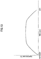
FIG.13 describes a graph representing transition of a temperature in a furnace in a situation of bonding of a rubber bush to a stabilizer bar in a conventional art. The horizontal axis inFIG. 13 represents the amount of time (min: minutes), and the vertical axis inFIG.13 represents the furnace temperature. - As is obvious from
FIG.13 , problems occur in that a rise of the furnace temperature is slow and thermal energy generated after the stabilizer bar is heated at around 160 degrees Celsius goes to waste. - In addition, since the entire stabilizer bar is heated, there is a possibility that extra thermal energy is consumed to lead to an increase in cost.
- Incidentally, in the case of such a continuous heating furnace using radiation heat and eradiation heat, a heat source is set to have a higher temperature than a set temperature in the furnace which is a set temperature at a time of bonding of an object, because of heat loss due to heat transfer by air and the like.
- Moreover, in order to allow the object to rise up to the set temperature as rapidly as possible from room temperature when the object enters the furnace, the set temperature of the heat source is set, in some cases, to be even higher in the vicinity of an entrance of the furnace as indicated by a two-dot chain line in
FIG. 5 . From the above, there is a high possibility that extra thermal energy is further consumed. - In view of the above actual situation, the present invention makes it an object thereof to provide a stabilizer manufacturing apparatus and a stabilizer manufacturing method that are capable of heat-bonding a rubber bush to a stabilizer at a low cost and with space saved.
- In order to solve the problems described above, the invention according to
claim 1 provides a stabilizer manufacturing apparatus that is adapted to bond a rubber bush which is a bush made of rubber interposed between a vehicle body and a stabilizer that suppresses a rolling phenomenon of a vehicle, to a rubber bush bonding location where an adhesive layer of the stabilizer is formed, the stabilizer manufacturing apparatus including: a curing furnace for heating the stabilizer that is conveyed by a manufacturing line conveying unit and has the rubber bush bonding location with which the rubber bush is press-contacted, to perform the bonding; a heat source device that heats air; a blower device that sends the air heated by the heat source device as hot air; and a plurality of nozzles that are disposed along the manufacturing line conveying unit in the curing furnace and adapted to blow the hot air at a near position from and against a location in the vicinity of the rubber bush bonding location of the stabilizer. - The invention according to claim 9 provides a stabilizer manufacturing method that realizes the stabilizer manufacturing apparatus according to
claim 1. - The inventions according to
claim 1 and claim 9 allow heat to be given by heat transfer from the vicinity of the rubber bush bonding location to the rubber bush bonding location, thus making it possible to reduce heat loss and achieve energy saving. In addition, a space required for heating the rubber bush bonding location is very small. - The invention according to claim 2 provides the stabilizer manufacturing apparatus according to
claim 1, wherein the nozzles each have a head that has a slant formed to be away from the stabilizer, from a side close to the rubber bush toward a side distant from the rubber bush, in a situation of the hot air being blown against the location. - The invention according to claim 10 provides a stabilizer manufacturing method that realizes the stabilizer manufacturing apparatus according to claim 2.
- The inventions according to claim 2 and claim 10 allow each head of the nozzles to have the slant formed to be away from the stabilizer, from the side close to the rubber bush toward the side distant from the rubber bush, in a situation of the hot air being blown against the location, thus allowing less hot air to hit the rubber bush and more hot air to hit the stabilizer. Therefore, deterioration of the rubber bush due to heat can be suppressed. Moreover, more heat is given to the stabilizer having high thermal conductivity than the rubber bush having low thermal conductivity, thus making it possible to efficiently and effectively carry out heating of the rubber bush bonding location of the stabilizer, through thermal conduction by the stabilizer having high thermal conductivity. Energy saving can be achieved on this point, too.
- The invention according to
claim 3 provides the stabilizer manufacturing apparatus according toclaim 1, wherein the nozzles each have an opening that is disposed to face the stabilizer close to the rubber bush, in a situation of the hot air being blown out through the opening of each nozzle. - The invention according to claim 11 provides a stabilizer manufacturing method that realizes the stabilizer manufacturing apparatus according to
claim 3. - The inventions according to
claim 3 and claim 11 allow the openings of the nozzles to be disposed to face the stabilizer close to the rubber bush, thus making it possible to avoid the hot air blown out through the openings of the nozzles from directly hitting the rubber bush and to suppress deterioration of the rubber bush as minimally as possible. - The invention according to
claim 4 provides the stabilizer manufacturing apparatus according toclaim 1, further including a reflective member that is disposed at a position on the opposite side of the nozzles to face the location in the vicinity of the rubber bush bonding location of the stabilizer, and reflects the hot air blown out through the nozzles to blow the hot air against the location close to the rubber bush on the stabilizer. - The invention according to claim 12 provides a stabilizer manufacturing method that realizes the stabilizer manufacturing apparatus according to
claim 4. - The inventions according to
claim 4 and claim 12 allow the reflective member to be disposed to reflect the hot air blown out through the nozzles to blow the hot air against the location close to the rubber bush on the stabilizer, thus allowing the nozzles to be only needed on one side and making it possible to effectively utilize heat of the hot air blown out through the nozzles. - Therefore, the manufacturing cost and running cost can be reduced and thus a decrease in cost can be achieved. Moreover, the nozzles are only needed on one side and the heat of the hot air blown out through the nozzles can be effectively utilized, thus making it possible to reduce energy consumption.
- The invention according to
claim 5 provides the stabilizer manufacturing apparatus according toclaim 4, wherein the reflective member has a concave shape which is concave to the location in the vicinity of the rubber bush bonding location of the stabilizer. - The invention according to
claim 5 allows the reflective member to have a concave shape which is concave to the location in the vicinity of the rubber bush bonding location of the stabilizer, thus making it possible to reflect the hot air blown out through the nozzles to blow the hot air with being effectively collected at and against the location in the vicinity of the rubber bush bonding location of the stabilizer. - Accordingly, thermal energy can be effectively transferred to the rubber bush bonding location of the stabilizer to heat the rubber bush bonding location and thus the energy can be effectively used.
- The invention according to claim 6 provides the stabilizer manufacturing apparatus according to
claim 4, further including a fixing jig that fixes the stabilizer to the manufacturing line conveying unit, wherein the reflective member is attached to the fixing jig. - The invention according to claim 13 provides a stabilizer manufacturing method that realizes the stabilizer manufacturing apparatus according to claim 6.
- The inventions according to claim 6 and claim 13 allow the reflective member to be attached to the fixing jig, thus allowing the reflective member to need only to have the smallest volume and an attachment structure of the reflective member to be simplified. Therefore, a decrease in cost can be achieved.
- The invention according to
claim 7 provides the stabilizer manufacturing apparatus according toclaim 1, wherein the stabilizer with which the rubber bush is press-contacted is conveyed by the manufacturing line conveying unit from an entrance to an exit of the curing furnace, and air volume of hot air blown out through the nozzles disposed on the entrance side of the curing furnace is set to be more than air volume of hot air blown out through the nozzles disposed on the exit side. - The invention according to claim 14 provides a stabilizer manufacturing method that realizes the stabilizer manufacturing apparatus according to
claim 7. - The inventions according to
claim 7 and claim 14 allow the air volume of hot air blown out through the nozzles to be set to be more on the entrance side of the curing furnace than on the exit side, thus making it possible to prevent the air volume from being used in vain, reduce the energy and achieve energy saving. - The invention according to
claim 8 provides the stabilizer manufacturing apparatus according toclaim 1, wherein a temperature at which the heat source device heats air is set to be a constant temperature. - The invention according to
claim 8 allows the temperature at which the heat source device heats air to be set to be a constant temperature, thus making it possible to reduce the configuration for controlling the temperature to decrease the manufacturing cost with a low failure rate, and to reduce maintenance work to increase reliability. - The present invention makes it possible to materialize a stabilizer manufacturing apparatus and a stabilizer manufacturing method that are capable of heat-bonding a rubber bush to a stabilizer at a low cost and with space saved.
-
-
FIG.1 is a perspective view of the vicinity of a stabilizer according to an embodiment of the present invention. -
FIG.2 is a conceptual perspective view showing a state of the stabilizer and a rubber bush in a curing process in a stabilizer manufacturing apparatus according to the embodiment. -
FIG.3 is a conceptual side view showing a state of the stabilizer and the rubber bush in a furnace in the curing process in the stabilizer manufacturing apparatus according to the embodiment. -
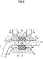
FIG.4 is a view taken in the direction of arrow A inFIG.2 , showing a state of the vicinity of a bonding location of the stabilizer and therubber bush 3, the vicinity being heated in the curing furnace. -
FIG.5 is a graph representing a temperature of a heat source in a situation of the stabilizer being moved from an entrance to an exit of the curing furnace. -
FIG. 6 is a graph representing air volume of hot air which is blown against the vicinity of the bonding location of the stabilizer from the entrance to the exit of the curing furnace, for the present invention (solid line) and a conventional art (two-dot chain line). -
FIG.7A is a view taken in the direction of arrow A inFIG.2 , showing a state of the bonding being carried out by hot air blown out through nozzles in a first modification. -
FIG. 7B is a perspective view including partial cross-section, showing the state of the bonding being carried out by hot air blown out through the nozzles in the first modification. -
FIG.8A is a view taken in the direction of arrow A inFIG.2 , showing a state of the bonding being carried out by hot air blown out through nozzles in a second modification. -
FIG. 8B is a perspective view including partial cross-section, showing the state of the bonding being carried out by hot air blown out through the nozzles in the second modification. -
FIG.9A is a view taken in the direction of arrow A inFIG.2 , showing a state of the bonding being carried out by hot air blown out through nozzles in a third modification. -
FIG. 9B is a perspective view including partial cross-section, showing the state of the bonding being carried out by hot air blown out through the nozzles in the third modification. -
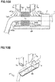
FIG. 10A is a view taken in the direction of arrow A inFIG. 2 , showing a state of the bonding being carried out by hot air blown out through nozzles in a fourth modification. -
FIG. 10B is a perspective view showing the state of the bonding being carried out by hot air blown out through the nozzles in the fourth modification. -
FIG.11 is a view taken in the direction of arrow A inFIG.2 , showing a state of the bonding being carried out by hot air blown out through nozzles in a fifth modification. -
FIG.12 is a view taken in the direction of arrow A inFIG.2 , showing a state of the bonding being carried out by hot air blown out through nozzles in a sixth modification. -
FIG.13 is a graph representing transition of a temperature in a furnace in a situation of bonding of a rubber bush to a stabilizer bar in a conventional art. - Embodiments of the present invention will be hereinafter described in detail with reference to the drawings as appropriate.
-
FIG.1 describes a perspective view of the vicinity of a stabilizer according to an embodiment of the present invention. - The embodiment describes a
stabilizer 1 that is used to cancel deviation of positions of right and left wheels W of a vehicle (not shown). - The vehicle is equipped with a pair of suspension mechanisms 2 attached to the right and left wheels W, and the
stabilizer 1 to which the pair of suspension mechanisms 2 is connected. - The
stabilizer 1 functions, for example, when the vehicle turns to allow a vehicle body (not shown) to be inclined (rolling phenomenon), to torsionally deform depending on the deviation of positions of the right and left wheels W and generate an elastic force for restoring the torsional deformation to its original state, to thereby suppress the rolling phenomenon of the vehicle. - The
stabilizer 1 is formed of, for example, spring steel. Examples of the spring steel that can be used include SUP3, SUP6, SUP7, SUP9, SUP9A, SUP10, SUP11A, SUP12 and SUP13 that are defined in the Japanese Industrial Standards (JIS) G 4801:2005, and SUP10 of these examples is most preferable. - The
stabilizer 1 includes right and leftarm sections 1a that are connected to the pair of right and left suspension mechanisms 2, respectively, and astabilizer bar 1b that allows the torsional deformation and its restoration to be carried out therein, and is formed into nearly U shape. - A pair of
rubber bushes 3 which are bushes made of rubber is bonded to a central part of thestabilizer bar 1b, with being spaced each other. Therubber bush 3 is a buffer that absorbs and reduces impact, vibration and the like exerted on the right and left wheels. Therubber bush 3 is firmly attached to a bracket 9 using bolts, and the bracket 9 is fixed to the vehicle body using bolts. - The
stabilizer 1 to which therubber bushes 3 are fixed by bonding is manufactured as described below. - First, the
stabilizer 1 is formed into a predetermined final shape (seeFIG.1 ) using pipe material or rod material composed of spring steel as the material. Subsequently, coating is applied on the surface of the material of the final shape of thestabilizer 1. Then, a coated film composed of an epoxy resin-based resin layer is formed on abonding location 1s (seeFIG.4 ) for therubber bush 3 of the material of the final shape, a primer layer is formed on the resin layer, and a top coat layer is formed on the primer layer. The resin layer, the primer layer and the top coat layer that are formed on thestabilizer 1 constitute an adhesive layer. - Subsequently, the
rubber bushes 3 are each compressed by a jig to be fixed to twobonding locations 1s that are spaced each other on the central part of thestabilizer 1. Then, a curing process is applied in which therubber bushes 3 with being compressed and deflected by the jigs are introduced into a curing furnace R (seeFIG. 2 andFIG. 3 ) to be heated and cured as described in detail below. - In the curing process, the resin layer on the surface of the material of the
stabilizer 1 and the primer layer are joined together by an anchor effect, an intermolecular bond or the like. Also, the primer layer and the top coat layer are joined together by an ion bond. Moreover, the top coat layer on the surface of the material of thestabilizer 1 and therubber bushes 3 are reliably joined together by vulcanization reaction, allowing therubber bushes 3 to be bonded to thestabilizer 1. - Next, description will be given of the curing process.
- In the curing process, as described above, the pair of
rubber bushes 3 are compressed by the jig (not shown) to be fixed to the twobonding locations 1s at which the adhesive layer is formed on the central part of thestabilizer 1. Then, heating is continued for about 32 minutes at about 160 degrees Celsius in the curing furnace R, thereby allowing the pair ofrubber bushes 3 to be bonded via the adhesive layer to the twobonding locations 1s on the central part of thestabilizer 1, respectively. -
FIG. 2 describes a conceptual perspective view showing a state of the stabilizer and the rubber bush in the curing process in a stabilizer manufacturing apparatus according to the embodiment, andFIG.3 describes a conceptual side view showing a state of the stabilizer and the rubber bush in the furnace in the curing process in the stabilizer manufacturing apparatus according to the embodiment. -
FIG.4 describes a view taken in the direction of arrow A inFIG.2 , showing a state of the vicinity of the bonding location of the stabilizer and the rubber bush, the vicinity being heated in the curing furnace. - Note that, in order to facilitate the understanding,
FIG.3 illustratesnozzles 7 each being disposed on one side of onerubber bush 3 of the pair on thestabilizer 1. Moreover,FIG.3 omits illustration as tonozzles 7 each being disposed on the other side of the onerubber bush 3 and pairs ofnozzles 7 each pair being disposed on both sides of theother rubber bush 3 of the pair on thestabilizer 1. - The stabilizer manufacturing apparatus S in the embodiment is provided with the curing furnace R for heating the
rubber bush 3 to bond it to thebonding location 1s of thestabilizer 1. - The curing furnace R in which the curing process is carried out is a hot-air type furnace that uses hot air for heating. The curing process in the curing furnace R is controlled by a control unit (not shown), e.g., a PLC (Programmable Logic Controller).
- In the curing furnace R, a plurality of
stabilizers 1 to which therubber bushes 3 are compressively fixed by the jigs (not shown) are continuously conveyed on the line (see outlined arrows α1 inFIG.2 andFIG.3 ). More specifically, the pair ofrubber bushes 3 are compressed by the jigs (not shown), respectively, to be fixed to (press-contacted with) the twobonding locations 1s on the central part of each of thestabilizers 1 that are mounted on aconveyor belt 4. Then, thestabilizer 1 having the pair ofrubber bushes 3 press-contacted therewith is conveyed in the curing furnace R to be heated for about 32 minutes at about 160 degrees Celsius, thereby allowing the bonding to be carried out. - As shown in
FIG.3 , provided in the curing furnace R is a hotair generating device 5 that maintains a heat source at a constant temperature and sends hot air. Where the heating is carried out for about 32 minutes at about 160 degrees Celsius, the temperature of the heat source is set to be about 170 (plus 0 to 30) degrees Celsius, i.e., about 170 degrees Celsius to about 200 degrees Celsius. Note that the bonding temperature of about 160 degrees Celsius and the time of about 32 minutes in the heating, and the temperature of the heat source in this case, are merely one example and can be appropriately selected. - The hot
air generating device 5 is provided with an air inlet (not shown) for taking in external air, the heat source such as a heater (not shown) that heats the taken-in air at a predetermined temperature, and fans f1, f2, f3 that send the air heated by the heat source to thenozzles 7. - The air taken in through the air intake is heated by the heater (not shown), changed to hot air using the fans f1, f2, f3, and sent through
ducts nozzles 7. The fans f1, f2, f3 shown inFIG. 3 are schematically illustrated, and the number, locations and the like of the fans f1, f2, f3 can be appropriately set depending on air volume blown out through therespective nozzles 7. - For example, hot air of air volume "High" is supplied by the fan f1 through the
duct 6a to thenozzles 7. - Hot air of air volume "Low" is supplied by the fan f2 through the
duct 6b to thenozzles 7. - Hot air of air volume "Low" is supplied by the fan f3 through the
duct 6c to thenozzles 7. - Then, hot air is blown through an opening 7s1 of a
head 7s (FIG.4 ) of thenozzle 7, at a near position from and against the location in the vicinity (details are described later) of thebonding location 1s for therubber bush 3 on thestabilizer 1. The opening 7s1 of thehead 7s of thenozzle 7 does not directly face therubber bush 3, but faces the location in the vicinity of thebonding location 1s for therubber bush 3. This configuration avoids the hot air blown out through thenozzles 7 from directly hitting therubber bush 3 and suppresses deterioration of therubber bush 3 due to heat. - That is, in the curing furnace R, with the temperature of the heat source in the hot
air generating device 5 being kept constant, the air volume of hot air allows heat to be given to the location in the vicinity of thebonding location 1s for therubber bush 3 on thestabilizer 1, and thermal conduction mainly by thestabilizer 1 allows control of the elevated temperature process to be carried out at thebonding location 1s for therubber bush 3. - As shown in
FIG.4 , thenozzles 7 forming hot-air outlets (openings 7s1) are provided at two locations against which the hot air is blown and for onerubber bush 3 that is press-contacted with thestabilizer 1, that is, to constitute a pair ofnozzles 7. - The locations against which the hot air is blown, that is, the pair of
nozzles 7, are disposed with being spaced each other in place along the conveyor belt 4 (seeFIG.2 andFIG.3 ). - Moreover, a
reflective plate 8 is provided on the opposite side of the twonozzles 7. Thereflective plate 8 is adapted to reflect hot air, which is blown out through thenozzles 7 and passes through neighboring regions 1a1 in the vicinity of thebonding location 1s between thestabilizer 1 and therubber bush 3, again on the vicinity of thebonding location 1s between thestabilizer 1 and therubber bush 3. - That is, the hot air n1 blown out through the
nozzles 7 and passing through the neighboring regions 1a1 in the vicinity of thebonding location 1s between thestabilizer 1 and therubber bush 3 hits thereflective plate 8 to be reflected and is directed again to the neighboring regions 1a1 in the vicinity of thebonding location 1s between thestabilizer 1 and therubber bush 3. - The
reflective plate 8 is continuously provided in the direction of movement of the conveyor belt 4 (the direction in which the front and back side of the space inFIG.4 is penetrated through) . Alternatively, a plurality ofreflective plates 8 are provided with being spaced each other at least only at areas on which the hot air blown out through the pair ofnozzles 7 appropriately provided is reflected as shown inFIG.4 . - The material of the
reflective plate 8 can be arbitrarily selected as long as thereflective plate 8 can reflect the hot air blown out through thenozzles 7 on the location (neighboring regions 1a1) in the vicinity of thebonding location 1s for therubber bush 3 on thestabilizer 1. For example, an iron plate to which rust-proof treatment is applied, e.g., a stainless steel plate, is provided as thereflective plate 8. Note that it is preferable in the light of forming and cost that the stainless steel plate is easy to be formed so as to allow a thickness thereof to be equal to or less than a predetermined thickness. - The
head 7s of thenozzle 7, which forms the opening 7s1 that is a hot-air outlet, is formed to allow a side close to therubber bush 3 to extend to the vicinity of thestabilizer 1 to be made longer, and to allow a side opposite to therubber bush 3 to be away from thestabilizer 1 to be made shorter, and has a slant shape such that a tube is cut at a slant. That is, the opening 7s1 of thenozzle 7 has an elliptically shaped opening which is obliquely slanted. This allows air volume of the hot air directed to therubber bush 3 to be lessened. - In addition, orientation of the hot air n1 blown out through the
nozzles 7, in other words, the location which the opening 7s1 of thenozzle 7 faces, is allowed to be the location (neighboring regions 1a1) close to therubber bush 3 on thestabilizer 1, thereby allowing the hot air blown out through thenozzles 7 not to directly hit therubber bush 3. - This allows air volume of the hot air n1 hitting the
rubber bush 3 to be decreased to the extent possible, thermal damage exerted on therubber bush 3 to be reduced, and thermal deterioration of therubber bush 3 to be suppressed as minimally as possible. - The hot air n1 which is blown out through the
nozzles 7 and hits the neighboring regions 1a1 in the vicinity of thebonding location 1s of thestabilizer 1, or the hot air n1 which passes through the neighboring regions 1a1, is reflected on thereflective plate 8 to be hot air n2, which in turn hits, from below, the neighboring regions 1a1 close to thebonding location 1s for therubber bush 3 and heats the regions. The heat which heats the region on thestabilizer 1 close to therubber bush 3 is propagated to thebonding location 1s for therubber bush 3, through thermal conduction in thestabilizer 1 having high thermal conductivity (see arrows β1 inFIG.4 ), and heats thebonding location 1s. - Moreover, the
bonding location 1s between therubber bush 3 and thestabilizer 1 is also heated by heat which is supplied from the external space of the rubber bush 3 (see arrows β2 inFIG.4 ) through radiation and air-mediated convection in the curing furnace R. - Herein, since the pair of right and left
rubber bushes 3 are provided on the stabilizer 1 (seeFIG.1 ), fournozzles 7 and tworeflective plates 8 are provided for onestabilizer 1 where thebonding locations 1s for the right and leftrubber bushes 3 are heated at the same area. Note that a configuration such that thebonding locations 1s for the right and leftrubber bushes 3 are heated at different areas may be adopted.FIG.2 andFIG.3 illustrate the configuration in which the right and leftrubber bushes 3 provided on onestabilizer 1 are heated at the same area. -
Fig. 5 describes a graph representing a temperature of the heat source in a situation of the stabilizer being moved from an entrance to an exit of the curing furnace. The horizontal axis inFIG.5 represents the amount of time (elapsed) from the entrance to the exit, and the vertical axis inFIG.5 represents the temperature of the heat source. - As indicated by a solid line in
FIG. 5 , the temperature of the heat source is kept at a constant temperature in the process of movement from the entrance to the exit of the curing furnace R, of thestabilizer 1 with which the pair ofrubber bushes 3 are press-contacted. - Note that, as long as the heating condition is met for the heating at about 160 degrees Celsius for about 32 minutes at the
bonding location 1s for therubber bush 3 on thestabilizer 1, a configuration may be adopted in which, for thestabilizer 1 with which therubber bushes 3 are press-contacted, the temperature of the heat source is set to be high in the vicinity of the entrance of the curing furnace R, as indicated by a two-dot chain line, and as thestabilizer 1 approaches the exit, the temperature of the heat source is decreased in two steps or multiple steps. Alternatively, a configuration may be adopted in which the temperature is decreased with at least one of a linear transition of temperature and a curved transition of temperature. Decreasing the temperature makes it possible to achieve energy saving. -
FIG.6 describes a graph representing air volume of hot air which is blown against the vicinity of thebonding location 1s of the stabilizer from the entrance to the exit of the curing furnace, for the present invention (solid line) and a conventional art (two-dot chain line). The horizontal axis inFIG.6 represents the amount of time (elapsed) from the entrance to the exit, and the vertical axis inFIG. 6 represents transition of the air volume blown out through thenozzles 7. - In the vicinity of the entrance of the curing furnace R, hot air having the maximum air volume is blown against the location in the vicinity of the
rubber bush 3 press-contacted with thestabilizer 1 to give a large amount of heat to the location, rapidly increasing the temperature of thebonding location 1s of thestabilizer 1 with which therubber bush 3 is press-contacted, to around 160 degrees Celsius. Thereafter, the air volume is decreased by one step, allowing the temperature of thebonding location 1s of thestabilizer 1 with which therubber bush 3 is press-contacted, to be maintained at around 160 degrees Celsius. - That is, the maximum air volume in the vicinity of the entrance of the curing furnace R allows the temperature of the
bonding location 1s of thestabilizer 1 with which therubber bush 3 is press-contacted, to be rapidly increased to around 160 degrees Celsius. Thereafter, the air volume is decreased by one step, allowing the temperature of thebonding location 1s of thestabilizer 1 with which therubber bush 3 is press-contacted, to be maintained for about 32 minutes at the temperature of about 160 degrees Celsius. - Herein, the temperature of the
stabilizer 1 in the vicinity of therubber bush 3 is measured with a thermocouple. Temperature measurement using the thermocouple may be carried out at a time of production line setting, or at a time of maintenance, or may be carried out in sampling inspection. - Note that, as long as the temperature of the
bonding location 1s of thestabilizer 1 with which therubber bush 3 is press-contacted is maintained at the temperature of about 160 degrees Celsius, a configuration may be adopted in which the air volume is changed in three steps as indicated by a two-dot chain line inFIG.6 , i.e., the temperature of thebonding location 1s of thestabilizer 1 with which therubber bush 3 is press-contacted is rapidly increased to the temperature of about 160 degrees Celsius in the first step, and then the air volume is decreased in two steps so as to maintain the temperature of about 160 degrees Celsius. Alternatively, as long as the temperature of thebonding location 1s for therubber bush 3 on thestabilizer 1 is maintained for about 32 minutes at about 160 degrees Celsius, a configuration for decreasing the air volume may adopt another configuration. - The
bonding location 1s between thestabilizer 1 and therubber bush 3 is heated for about 32 minutes at about 160 degrees Celsius in this way, allowing the bonding to be carried out. - The configuration described above allows the openings 7s1 of the
nozzles 7 to be disposed so as to allow the hot air to hit the neighboring regions 1a1 (seeFIG.4 ) in the vicinity of thebonding location 1s for therubber bush 3 on thestabilizer 1, thereby giving the heat to thebonding location 1s by heat transfer. Therefore, heat loss associated with heat transfer by air-mediated convection and radiation can be greatly reduced, as compared to a conventional continuous heating furnace. Consequently, energy saving can be achieved, which lessens the amount of emission of carbon dioxide and is good for the environment. - Moreover, the air volume of hot air blown out through the
nozzles 7 in the vicinity of the entrance of the curing furnace R is set to be higher to allow a large amount of heat to be given, and the air volume of hot air is set to be lower to allow a smaller amount of heat to be given as thestabilizer 1 approaches the exit of the curing furnace R, maintaining the predetermined temperature (about 160 degrees Celsius). This allows the temperature of thebonding location 1s for therubber bush 3 on thestabilizer 1 with which therubber bush 3 is press-contacted, to be increased to about 160 degrees Celsius, and then the temperature of about 160 degrees Celsius to be maintained. - Such regulation of the air volume of hot air allows the set temperature of the heat source in the hot
air generating device 5 to be constant in principle. This makes a configuration unnecessary, which changes the temperature in the hotair generating device 5, and a minimum number of ducts are only needed, thus making it possible to achieve a decrease in cost. - In addition, as shown in
FIG. 6 , the air volume in the vicinity of the entrance is made larger with rapid heating from the ambient temperature to allow for quick heating, and from the step of keeping of uniform heating at about 160 degrees Celsius, air volume required for keeping the amount of heat equivalent to radiative cooling is only needed. Therefore, the configuration such that the air volume is decreased in two steps from the initial air volume is basically adopted. However, the number of steps of the air volume may be appropriately changed to three or four steps. - This configuration makes it possible to suppress overheating even in case of trouble such as stagnation within the furnace because the temperature of the heat source in the hot
air generating device 5 is kept constant. - Moreover, the configuration such that the hot air is blown from the
nozzles 7 against the vicinity of the heating target (thebonding location 1s for therubber bush 3 on the stabilizer 1) is adopted, thus making it possible to reduce a space required for heating the heating target and achieve space saving. Moreover, increasing or decreasing the air volume blown out through thenozzles 7 makes it possible to carry out regulation such as shortening or lengthening the heating line. For example, when the air volume blown out through thenozzles 7 is increased, the amount of heat to be given to the heating target can be increased to shorten the heating line. - From the above, it is possible to materialize a stabilizer manufacturing apparatus and a stabilizer manufacturing method that are capable of heat-bonding the
rubber bushes 3 to thestabilizer 1 at a low cost and with space saved. -
FIG.7A describes a view taken in the direction of arrow A inFIG.2 , showing a state of the bonding being carried out by hot air blown out through nozzles in a first modification, andFIG.7B describes a perspective view including partial cross-section, showing the state of the bonding being carried out by hot air blown out through the nozzles in the first modification. - The first modification replaces the
reflective plate 8 having the shape of a flat plate in the above embodiment, with areflective plate 18 having a concave shape. - The other configuration is the same as the configuration of the embodiment, and thus the same component is shown with the same reference sign given and detailed description thereof is omitted.
- The
reflective plate 18 in the first modification is formed, in order to allow the hot air blown out through thenozzles 7 to be reflected without loss on the location in the vicinity of thebonding location 1s for therubber bush 3 on thestabilizer 1, into a concave shape with a curvature such that the vicinity (neighboring regions 1a1) of thebonding location 1s and therubber bush 3 are surrounded inside. - In other words, the
reflective plate 18 is formed into a concave shape which is concave to the vicinity (neighboring regions 1a1) of thebonding location 1s and therubber bush 3. - The
reflective plate 18 has a concave shape along the direction in which thestabilizers 1 are placed on the conveyor belt 4 (the direction in which the front and back side of the space inFIG.7A is penetrated through) (seeFIG.7B ). - This allows hot air n11 blown out through the
nozzles 7 to hit the neighboring regions 1a1 in the vicinity of therubber bush 3 on thestabilizer 1 and heat the regions. Then, the hot air n11 passing through thestabilizer 1 is reflected on thereflective plate 18 to be hot air n12, which in turn hits the neighboring regions 1a1 on the side opposite to thenozzles 7 in the vicinity of therubber bush 3 on thestabilizer 1 and heats the regions. - Note that, as long as the
reflective plate 18 is adapted to allow the hot air n11 blown out through thenozzles 7 to be reflected thereon to be the hot air n12, and allow the hot air n12 to hit the neighboring regions 1a1 on the side opposite to thenozzles 7 in the vicinity of therubber bush 3 on thestabilizer 1, thereflective plate 18 may be disposed separately for locations facing thenozzles 7, or may be formed into a continuous shape for the locations facing thenozzles 7. Note thatFIG.7B illustrates the case in which thereflective plate 18 is continuously formed. - The first modification allows the
reflective plate 18 to have a concave shape, thus allowing the hot air n11 blown out through thenozzles 7 directed to the neighboring regions 1a1 in the vicinity of therubber bush 3 on thestabilizer 1, to be efficiently reflected toward and hit the neighboring regions 1a1 in the vicinity of therubber bush 3 on thestabilizer 1. This makes it possible to effectively heat thebonding location 1s. Therefore, thebonding location 1s for therubber bush 3 on thestabilizer 1 can be heated efficiently and effectively through the thermal conduction by thestabilizer 1, thus reducing energy consumption. -
FIG.8A describes a view taken in the direction of arrow A inFIG.2 , showing a state of the bonding being carried out by hot air blown out through nozzles in a second modification, andFIG.8B describes a perspective view including partial cross-section, showing the state of the bonding being carried out by hot air blown out through the nozzles in the second modification. - The second modification replaces the
reflective plate 8 having the shape of a flat plate in the above embodiment, with areflective plate 28 having twoconcave shapes - The other configuration is the same as the configuration of the embodiment, and thus the same component is shown with the same reference sign given and detailed description thereof is omitted.
- The
reflective plate 28 in the second modification is formed, in order to allow the hot air blown out through thenozzles 7 to be reflected without loss on the locations (1a22, 1b22) in the vicinity of thebonding location 1s for therubber bush 3 on thestabilizer 1, into the twoconcave shapes bonding location 1s of thestabilizer 1 is surrounded inside. - In other words, the
reflective plate 28 has theconcave shapes bonding location 1s of thestabilizer 1. - The
reflective plate 28 has the concave shapes extending along the direction in which thestabilizers 1 are placed on the conveyor belt 4 (the direction in which the front and back side of the space inFIG.8A is penetrated through) (seeFIG.8B ). - This allows hot air n21a blown out through one
nozzle 7 to hit one neighboring region 1a21 in the vicinity of therubber bush 3 on thestabilizer 1 and heat the region. Then, the hot air n21a passing through thestabilizer 1 is reflected on theconcave shape 28a of thereflective plate 28 to be hot air n22a, which in turn hits one neighboring region 1a22 on the side opposite to the onenozzle 7 in the vicinity of therubber bush 3 on thestabilizer 1 and heats the region. - In the same way, hot air n21b blown out through the
other nozzle 7 hit the other neighboring region 1b21 in the vicinity of therubber bush 3 on thestabilizer 1 and heat the region. Then, the hot air n21b passing through thestabilizer 1 is reflected on theconcave shape 28b of thereflective plate 28 to be hot air n22b, which in turn hits the other neighboring region 1b22 on the side opposite to theother nozzle 7 in the vicinity of therubber bush 3 on thestabilizer 1 and heats the region. - Note that, as long as the
reflective plate 28 is adapted to allow the hot air n21a, n21b blown out through thenozzles 7 to be reflected thereon, and allow the hot air n22a, n22b to hit the neighboring regions 1a22, 1b22 on the side opposite to thenozzles 7 in the vicinity of therubber bush 3 on thestabilizer 1, thereflective plate 28 may be disposed separately for locations facing thenozzles 7, or may be formed into a continuous shape for the locations facing thenozzles 7. Note thatFIG.8B illustrates the case in which thereflective plate 28 is formed into a continuous shape for the locations facing thenozzles 7. - The second modification allows the
reflective plate 28 to have the twoconcave shapes nozzles 7 directed to the neighboring regions 1a21, 1b21 in the vicinity of therubber bush 3 on thestabilizer 1 can be efficiently reflected, and the reflected hot air n22a, n22b hit the neighboring regions 1a22, 1b22 on the side opposite to thenozzles 7 in the vicinity of therubber bush 3 on thestabilizer 1, thereby making it possible to effectively heat thebonding location 1s. - In addition, since the
reflective plate 28 has the twoconcave shapes nozzle 7 is effectively reflected. - Therefore, the
bonding location 1s for therubber bush 3 on thestabilizer 1 can be heated more efficiently and effectively, thus reducing energy consumption. -
FIG.9A describes a view taken in the direction of arrow A inFIG.2 , showing a state of the bonding being carried out by hot air blown out through nozzles in a third modification, andFIG.9B describes a perspective view including partial cross-section, showing the state of the bonding being carried out by hot air blown out through the nozzles in the third modification. - The third modification replaces the
reflective plate 28 having the twoconcave shapes reflective plates - The other configuration is the same as the configuration of the embodiment, and thus the same component is shown with the same reference sign given and detailed description thereof is omitted.
- The separated
reflective plates nozzles 7 to be reflected without loss on the locations (neighboring regions 1a32, 1b32) in the vicinity of thebonding location 1s for therubber bush 3 on thestabilizer 1, into two concave shapes with a curvature such that the vicinity (neighboring regions 1a32, 1b32) of thebonding location 1s of thestabilizer 1 is surrounded inside. - In other words, the
reflective plate 38a has the concave shape which is concave to the neighboring region 1a32 in the vicinity of thebonding location 1s of thestabilizer 1. Similarly, thereflective plate 38b has the concave shape which is concave to the neighboring region 1b32 in the vicinity of thebonding location 1s of thestabilizer 1. - The
reflective plates stabilizers 1 are placed on the conveyor belt 4 (the direction in which the front and back side of the space inFIG.9A is penetrated through) (seeFIG.9B ). - This allows hot air n31a blown out through one
nozzle 7 to hit one neighboring region 1a31 in the vicinity of therubber bush 3 on thestabilizer 1 and heat the region. Then, the hot air n31a passing through thestabilizer 1 is reflected on thereflective plate 38a having the concave shape to be hot air n32a, which in turn hits one neighboring region 1a32 on the side opposite to the onenozzle 7 in the vicinity of therubber bush 3 on thestabilizer 1 and heats the region. This makes it possible to heat thebonding location 1s through the thermal conduction by thestabilizer 1. - In the same way, hot air n31b blown out through the
other nozzle 7 hit the other neighboring region 1b31 in the vicinity of therubber bush 3 on thestabilizer 1 and heat the region. Then, the hot air n31b passing through thestabilizer 1 is reflected on thereflective plate 38b having the concave shape to be hot air n32b, which in turn hits the other neighboring region 1b32 on the side opposite to theother nozzle 7 in the vicinity of therubber bush 3 on thestabilizer 1 and heats the region. This makes it possible to heat thebonding location 1s through the thermal conduction by thestabilizer 1. - Note that, as long as each of the
reflective plates respective nozzles 7 to be reflected thereon, and allow the reflected hot air n32a, n32b to hit the neighboring regions 1a32, 1b32 on the side opposite to thenozzles 7 in the vicinity of therubber bush 3 on thestabilizer 1, thereflective plates nozzles 7, or may be formed into a continuous shape for the locations facing thenozzles 7. Note thatFIG.9B illustrates the case in which each of thereflective plates nozzles 7. - The third modification allows the two
reflective plates nozzles 7 directed to the neighboring regions 1a31, 1b31 in the vicinity of therubber bush 3 on thestabilizer 1 can be efficiently reflected, and the reflected hot air n32a, n32b hit the neighboring regions 1a32, 1b32 on the side opposite to thenozzles 7 in the vicinity of therubber bush 3 on thestabilizer 1, thereby making it possible to efficiently and effectively heat thebonding location 1s through the thermal conduction by thestabilizer 1. - In addition, since the two
reflective plates nozzle 7 is effectively reflected. - Also, since the two
reflective plates - Therefore, the
bonding location 1s for therubber bush 3 on thestabilizer 1 can be heated efficiently and effectively through the thermal conduction, thus reducing energy consumption. - Accordingly, a further decrease in cost can be achieved.
-
FIG.10A describes a view taken in the direction of arrow A inFIG.2 , showing a state of the bonding being carried out by hot air blown out through nozzles in a fourth modification, andFIG.10B describes a perspective view showing the state of the bonding being carried out by hot air blown out through the nozzles in the fourth modification. - The fourth modification replaces the reflective plate in the above embodiment, with a configuration having a
reflective plate 48 fixed to a fixing jig J that fixes thestabilizer 1 to theconveyor belt 4 adapted to move in the curing furnace R. - The other configuration is the same as the configuration of the embodiment, and thus the same component is shown with the same reference sign given and detailed description thereof is omitted.
- The
reflective plate 48 in the fourth modification has a concave shape with a curvature such that it surrounds neighboring regions 1a42, 1b42 in the vicinity of thebonding location 1s for therubber bush 3 on thestabilizer 1. - In other words, the
reflective plate 48 has the concave shape which is concave to the neighboring regions 1a42, 1b42 in the vicinity of thebonding location 1s for therubber bush 3 on thestabilizer 1. - Moreover, the
reflective plate 48 is configured to be fixed to the fixing jig J used for attaching thestabilizer 1 to theconveyor belt 4. - The
reflective plate 48 is adapted to reflect thereon hot air n41a blown out through thenozzles 7, to be hot air n42a. The hot air n41a heats a neighboring region 1a41 on thestabilizer 1, and the reflected hot air n42a heats the neighboring region 1a42 on thestabilizer 1. - Also, the
reflective plate 48 is adapted to reflect thereon hot air n41b blown out through thenozzles 7, to be hot air n42b. The hot air n41b heats a neighboring region 1b41 on thestabilizer 1, and the reflected hot air n42b heats the neighboring region 1b42 on thestabilizer 1. - Note that a reflective plate (not shown) located on the other side of the
stabilizer 1 is also configured to be fixed to the fixing jig J in the same manner as thereflective plate 48. - The fourth modification allows the
reflective plate 48 that is adapted to reflect thereon the hot air n41a, n41b blown out through therespective nozzles 7, to be fixed to the fixing jig J, thus making it possible to simplify an attachment structure of thereflective plate 48 and achieve a decrease in cost. - Moreover, the
reflective plate 48 that reflects thereon the hot air n41a, n41b blown out through thenozzles 7 is fixed to the fixing jig J for thestabilizer 1 to be moved together with thestabilizer 1. - Therefore, the
reflective plate 48 need not be provided for each of thenozzles 7 that are disposed along the line in the curing furnace R, thus allowing the size of thereflective plate 48 to be reduced to the minimum necessary. - Accordingly, material for the
reflective plate 48 needs only the smallest volume, thus making it possible to reduce a material cost and achieve a decrease in cost. -
FIG.11 describes a view taken in the direction of arrow A inFIG.2 , showing a state of the bonding being carried out by hot air blown out through nozzles in a fifth modification. - The fifth modification replaces the
nozzles 7 in the above embodiment, withnozzles nozzles - The other configuration is the same as the configuration of the embodiment, and thus the same component is shown with the same reference sign given and detailed description thereof is omitted.
- The fifth modification allows a pair of
nozzles stabilizer 1 in the vicinity of therubber bush 3 that is press-contacted with thestabilizer 1, and allows a pair ofnozzles - The
stabilizer 1 and therubber bush 3 press-contacted with thestabilizer 1 are fixed to theconveyor belt 4 to move on the line in the curing furnace R. - Heads 57as, 57as of the
nozzles stabilizer 1, toward the side distant from therubber bush 3. Similarly, heads 57bs, 57bs of thenozzles stabilizer 1, toward the side distant from therubber bush 3. - Moreover, the heads 57as, 57as of the
nozzles rubber bush 3 that is press-contacted with thestabilizer 1. Similarly, the heads 57bs, 57bs of thenozzles rubber bush 3 that is press-contacted with thestabilizer 1. - The fifth modification allows the
nozzles stabilizer 1 in the vicinity of therubber bush 3 that is press-contacted with thestabilizer 1, and allows thenozzles bonding location 1s for therubber bush 3 on thestabilizer 1. Therefore, a larger amount of heat can be given to thebonding location 1s for therubber bush 3 on thestabilizer 1, allowing heating of thebonding location 1s to be effectively carried out. - Moreover, since the
nozzles rubber bush 3 that is press-contacted with thestabilizer 1, the hot air blown out through thenozzles -
FIG.12 describes a view taken in the direction of arrow A inFIG.2 , showing a state of the bonding being carried out by hot air blown out through nozzles in a sixth modification. - The sixth modification replaces the
nozzles nozzles - The other configuration is the same as the configuration of the embodiment, and thus the same component is shown with the same reference sign given and detailed description thereof is omitted.
- The sixth modification allows a pair of
nozzles rubber bush 3 that is press-contacted with thestabilizer 1, and allows a pair ofnozzles - The
stabilizer 1 and therubber bush 3 press-contacted with thestabilizer 1 are fixed to theconveyor belt 4 to move on the line in the curing furnace R. - The heads 67as, 67as, 67bs, 67bs of the
nozzles - Moreover, the heads 67as, 67as of the
nozzles stabilizer 1 in the vicinity of thebonding location 1s for therubber bush 3 that is press-contacted with thestabilizer 1. Similarly, the heads 67bs, 67bs of thenozzles stabilizer 1 in the vicinity of thebonding location 1s for therubber bush 3 that is press-contacted with thestabilizer 1. - The sixth modification allows the
nozzles rubber bush 3 that is press-contacted with thestabilizer 1, and allows thenozzles bonding location 1s for therubber bush 3 on thestabilizer 1. Therefore, a larger amount of heat can be given to thebonding location 1s for therubber bush 3 on thestabilizer 1. - Moreover, since the
nozzles bonding location 1s for therubber bush 3 that is press-contacted with thestabilizer 1, the hot air blown out through thenozzles - In addition, since the heads 67as, 67as, 67bs, 67bs of the
nozzles nozzles -
- 1. Although, in the above embodiment and the above modifications, the reflective plate of a plate material has been illustrated as the reflective member, the reflective member may be composed of a member in the form of a block other than the plate material as long as it can reflect hot air, and shapes thereof can be arbitrarily selected.
- 2. The configuration of the above sixth modification, in which the heads 67as, 67as, 67bs, 67bs of the
nozzles - 3. A configuration may be adopted which is obtained by suitably selecting from among and combining together the configurations of the above embodiment and the above first to sixth modifications.
- Note that the present invention is not limited to the above embodiment and the above first to sixth modifications, and may include various embodiments. For example, the above embodiment has been described for a better understanding of the present invention, and is not necessarily limited to what includes all of the described configurations. For example, an embodiment such that some of the described configurations are included may be adopted.
-
- 1: Stabilizer
- 1a1: Neighboring region (Location in the vicinity of a rubber bush bonding location)
- 1a21, 1a22, 1b21, 1b22: Neighboring region (Location in the vicinity of a rubber bush bonding location)
- 1a31, 1a32, 1b31, 1b32: Neighboring region (Location in the vicinity of a rubber bush bonding location)
- 1a41, 1a42, 1b41, 1b42 : Neighboring region (Location in the vicinity of a rubber bush bonding location)
- 1s: Bonding location (Rubber bush bonding location)
- 3: Rubber bush
- 4: Conveyor belt (Manufacturing line conveying unit)
- 5: Hot air generating device (Heat source device)
- 7, 57a, 57b, 67a, 67b: Nozzle
- 7s, 57as, 57bs: Head
- 8, 18, 28, 38a, 38b, 48: Reflective plate (Reflective member) f1, f2, f3: Fan (Blower device)
- J: Fixing jig
- R: Curing furnace
- S: Stabilizer manufacturing apparatus
Claims (14)
- A stabilizer manufacturing apparatus that is adapted to bond a rubber bush which is a bush made of rubber interposed between a vehicle body and a stabilizer that suppresses a rolling phenomenon of a vehicle, to a rubber bush bonding location where an adhesive layer of the stabilizer is formed, the apparatus comprising:a curing furnace for heating the stabilizer that is conveyed by a manufacturing line conveying unit and has the rubber bush bonding location with which the rubber bush is press-contacted, to perform the bonding;a heat source device that heats air;a blower device that sends the air heated by the heat source device as hot air; anda plurality of nozzles that are disposed along the manufacturing line conveying unit in the curing furnace and adapted to blow the hot air at a near position from and against a location in the vicinity of the rubber bush bonding location of the stabilizer.
- The stabilizer manufacturing apparatus according to claim 1, wherein
the nozzles each have a head that has a slant formed to be away from the stabilizer, from a side close to the rubber bush toward a side distant from the rubber bush, in a situation of the hot air being blown against the location. - The stabilizer manufacturing apparatus according to claim 1, wherein
the nozzles each have an opening that is disposed to face the stabilizer close to the rubber bush, in a situation of the hot air being blown out through the opening of each nozzle. - The stabilizer manufacturing apparatus according to claim 1, further comprising
a reflective member that is disposed at a position on the opposite side of the nozzles to face the location in the vicinity of the rubber bush bonding location of the stabilizer, and reflects the hot air blown out through the nozzles to blow the hot air against the location close to the rubber bush on the stabilizer. - The stabilizer manufacturing apparatus according to claim 4, wherein
the reflective member has a concave shape which is concave to the location in the vicinity of the rubber bush bonding location of the stabilizer. - The stabilizer manufacturing apparatus according to claim 4, further comprising
a fixing jig that fixes the stabilizer to the manufacturing line conveying unit, wherein
the reflective member is attached to the fixing jig. - The stabilizer manufacturing apparatus according to claim 1, wherein
the stabilizer with which the rubber bush is press-contacted is conveyed by the manufacturing line conveying unit from an entrance to an exit of the curing furnace, and
air volume of hot air blown out through the nozzles disposed on the entrance side of the curing furnace is set to be more than air volume of hot air blown out through the nozzles disposed on the exit side. - The stabilizer manufacturing apparatus according to claim 1, wherein
a temperature at which the heat source device heats air is set to be a constant temperature. - A stabilizer manufacturing method that includes bonding a rubber bush which is a bush made of rubber interposed between a vehicle body and a stabilizer that suppresses a rolling phenomenon of a vehicle, to a rubber bush bonding location where an adhesive layer of the stabilizer is formed, the method comprising:heating air by means of a heat source device;sending, by means of a blower device, heated air as hot air to a plurality of nozzles that are disposed along a manufacturing line conveying unit;conveying in a curing furnace, by means of the manufacturing line conveying unit, the stabilizer having the rubber bush bonding location with which the rubber bush is press-contacted; andblowing, by means of the nozzles, the hot air at a near position from and against a location in the vicinity of the rubber bush bonding location of the stabilizer.
- The stabilizer manufacturing method according to claim 9, wherein
the nozzles each have a head that has a slant formed to be away from the stabilizer, from a side close to the rubber bush toward a side distant from the rubber bush, in a situation of the hot air being blown against the location. - The stabilizer manufacturing method according to claim 9, wherein
the nozzles each have an opening that is disposed to face the stabilizer close to the rubber bush, in a situation of the hot air being blown out through the opening of each nozzle. - The stabilizer manufacturing method according to claim 9, further comprising
reflecting, by means of a reflective member, the hot air blown out through the nozzles to blow the hot air against the location close to the rubber bush on the stabilizer. - The stabilizer manufacturing method according to claim 12, wherein
the reflective member is attached to a fixing jig that fixes the stabilizer to the manufacturing line conveying unit. - The stabilizer manufacturing method according to claim 9, wherein
air volume of hot air blown out through the nozzles disposed on the entrance side of the curing furnace is set to be more than air volume of hot air blown out through the nozzles disposed on the exit side.
Applications Claiming Priority (2)
| Application Number | Priority Date | Filing Date | Title |
|---|---|---|---|
| JP2014149556A JP6444082B2 (en) | 2014-07-23 | 2014-07-23 | Stabilizer manufacturing apparatus and method |
| PCT/JP2015/070570 WO2016013519A1 (en) | 2014-07-23 | 2015-07-17 | Stabilizer manufacturing device and method therefor |
Publications (2)
| Publication Number | Publication Date |
|---|---|
| EP3173265A1 true EP3173265A1 (en) | 2017-05-31 |
| EP3173265A4 EP3173265A4 (en) | 2018-04-04 |
Family
ID=55163044
Family Applications (1)
| Application Number | Title | Priority Date | Filing Date |
|---|---|---|---|
| EP15824883.1A Withdrawn EP3173265A4 (en) | 2014-07-23 | 2015-07-17 | Stabilizer manufacturing apparatus and stabilizer manufacturing method |
Country Status (5)
| Country | Link |
|---|---|
| US (1) | US10259285B2 (en) |
| EP (1) | EP3173265A4 (en) |
| JP (1) | JP6444082B2 (en) |
| CN (1) | CN106536240B (en) |
| WO (1) | WO2016013519A1 (en) |
Families Citing this family (6)
| Publication number | Priority date | Publication date | Assignee | Title |
|---|---|---|---|---|
| JP7398901B2 (en) | 2018-08-28 | 2023-12-15 | 旭化成株式会社 | Modified conjugated diene polymer composition, rubber composition, and method for producing rubber composition |
| CN109080157B (en) * | 2018-09-21 | 2024-04-02 | 德奥福臻越智能机器人(杭州)有限公司 | Heating device |
| JP7095572B2 (en) * | 2018-11-28 | 2022-07-05 | トヨタ自動車株式会社 | Stabilizer device and manufacturing method of stabilizer device |
| JP7147528B2 (en) * | 2018-12-11 | 2022-10-05 | トヨタ自動車株式会社 | Stabilizer device and stabilizer system including the same |
| CN111844769A (en) * | 2020-08-21 | 2020-10-30 | 宁波恒元精工管阀科技有限公司 | Anti-corrosion processing method of steel-plastic conversion pipe |
| CN118906734B (en) * | 2024-09-12 | 2025-02-11 | 苏州威通重卡汽配有限公司 | Stabilizer bar assembly for new energy heavy truck |
Family Cites Families (29)
| Publication number | Priority date | Publication date | Assignee | Title |
|---|---|---|---|---|
| DE1811467A1 (en) * | 1968-11-28 | 1970-06-18 | Henkel & Cie Gmbh | Process for coating strand-like structures with adhesion promoters for rubber |
| US4122321A (en) * | 1977-02-16 | 1978-10-24 | Park-Ohio Industries, Inc. | Induction heating furnace |
| JPS58125613U (en) * | 1982-07-21 | 1983-08-26 | 株式会社日立製作所 | Fin pipe manufacturing equipment |
| JPS60131243A (en) * | 1983-12-19 | 1985-07-12 | 積水化学工業株式会社 | Automatic pasting device for heat-insulating material for table flap |
| JPS62152564A (en) * | 1985-12-27 | 1987-07-07 | Trinity Ind Corp | Drying oven for painting |
| US4781054A (en) * | 1986-12-19 | 1988-11-01 | Rockwell International Suspension Systems Company | Apparatus for bending and forming heated tubular workpieces |
| JP2778838B2 (en) * | 1990-12-25 | 1998-07-23 | 日本発条株式会社 | Furnace for heat treatment and temperature control method of this furnace |
| JP2660105B2 (en) * | 1990-12-27 | 1997-10-08 | 日本発条株式会社 | Round bar material transfer device |
| JP2000177009A (en) * | 1998-12-16 | 2000-06-27 | Sekisui Chem Co Ltd | Manufacturing method of synthetic resin lining tube |
| JP2001270315A (en) * | 2000-03-24 | 2001-10-02 | Tokai Rubber Ind Ltd | Stabilizer bar with rubber bush |
| JP2006027311A (en) | 2004-07-12 | 2006-02-02 | Toyo Tire & Rubber Co Ltd | Stabilizer bar with rubber bush |
| JP4560376B2 (en) * | 2004-10-29 | 2010-10-13 | 東海ゴム工業株式会社 | Stabilizer bush |
| JP2006170293A (en) * | 2004-12-14 | 2006-06-29 | Toyo Tire & Rubber Co Ltd | Vibration isolator and its mounting method |
| JP4004512B2 (en) * | 2005-04-15 | 2007-11-07 | 東洋ゴム工業株式会社 | Manufacturing method of stabilizer bar with rubber bush |
| US8168920B2 (en) * | 2007-09-11 | 2012-05-01 | Shibuya Kogyo Co., Ltd. | Bonding device |
| JP5398192B2 (en) * | 2008-07-29 | 2014-01-29 | 日本発條株式会社 | Stabilizer device and manufacturing method thereof |
| JP2010185649A (en) * | 2009-01-15 | 2010-08-26 | Omron Corp | Hot air supply device and hot air supply method |
| DE112011100846T8 (en) * | 2010-03-08 | 2013-03-14 | Chuo Hatsujo Kabushiki Kaisha | Massive stabilizer, steel material for the solid stabilizer and manufacturing process of the solid stabilizer |
| JP5550405B2 (en) * | 2010-03-23 | 2014-07-16 | 中央発條株式会社 | Spring manufacturing method |
| DE102010022487A1 (en) * | 2010-06-02 | 2011-12-08 | Benteler Automobiltechnik Gmbh | Method for connecting a rubber bearing to a bearing for a motor vehicle and a device for connecting a rubber bearing to a bearing |
| JP5478472B2 (en) | 2010-12-07 | 2014-04-23 | 日本発條株式会社 | Bush and bracket integrated stabilizer bar |
| DE102011112077B4 (en) | 2011-09-01 | 2013-04-11 | ThyssenKrupp Federn und Stabilisatoren GmbH | Production plant for the production of products from cylindrical metal bars |
| JP5909134B2 (en) * | 2012-03-30 | 2016-04-26 | 富士重工業株式会社 | Precure device |
| JP2013258313A (en) * | 2012-06-13 | 2013-12-26 | Hitachi Chemical Co Ltd | Manufacturing method of solar cell module |
| US10276857B2 (en) * | 2012-09-25 | 2019-04-30 | Toyota Jidosha Kabushiki Kaisha | Method of manufacturing electrode for secondary battery and hot-gas drying furnace |
| CN103231637B (en) * | 2013-04-18 | 2015-08-12 | 安徽中鼎密封件股份有限公司 | The connection structure of a kind of Panhard rod and stabilizer bar bushing and manufacture craft thereof |
| CN103317994B (en) * | 2013-06-26 | 2016-05-11 | 上汽大众汽车有限公司 | The manufacture method of automobile stabilizer bar |
| JP6542516B2 (en) * | 2014-08-28 | 2019-07-10 | 三菱製鋼株式会社 | Method of manufacturing stabilizer bar with rubber bush |
| JP2017177911A (en) * | 2016-03-29 | 2017-10-05 | 住友理工株式会社 | Manufacturing method of stabilizer bar with rubber bush |
-
2014
- 2014-07-23 JP JP2014149556A patent/JP6444082B2/en active Active
-
2015
- 2015-07-17 WO PCT/JP2015/070570 patent/WO2016013519A1/en not_active Ceased
- 2015-07-17 EP EP15824883.1A patent/EP3173265A4/en not_active Withdrawn
- 2015-07-17 US US15/327,587 patent/US10259285B2/en not_active Expired - Fee Related
- 2015-07-17 CN CN201580039783.7A patent/CN106536240B/en not_active Expired - Fee Related
Also Published As
| Publication number | Publication date |
|---|---|
| WO2016013519A8 (en) | 2017-02-16 |
| WO2016013519A1 (en) | 2016-01-28 |
| EP3173265A4 (en) | 2018-04-04 |
| JP2016022871A (en) | 2016-02-08 |
| US10259285B2 (en) | 2019-04-16 |
| CN106536240A (en) | 2017-03-22 |
| JP6444082B2 (en) | 2018-12-26 |
| CN106536240B (en) | 2019-05-31 |
| US20170174036A1 (en) | 2017-06-22 |
Similar Documents
| Publication | Publication Date | Title |
|---|---|---|
| US10259285B2 (en) | Stabilizer manufacturing apparatus and stabilizer manufacturing method | |
| CN105339158B (en) | The heater of prefabricated component | |
| CN203923006U (en) | A kind of toughened glass production line | |
| US10525625B2 (en) | Plasticizing unit including a thermal separating device and an active tempering device | |
| US20130291592A1 (en) | Method for heating glass sheets | |
| JP5729059B2 (en) | Heat-treated steel or bending member manufacturing apparatus and manufacturing method | |
| CN107052106A (en) | Structure member and manufacture method | |
| KR102664183B1 (en) | Curved glass reinforcement with stress pattern weakening effect | |
| JP4809633B2 (en) | Method and apparatus for heating glass panels | |
| US10471490B2 (en) | Machine and method of bending a longitudinal cylindrical pipe | |
| KR101709760B1 (en) | Hardening apparatus and method for coating on plate, and Near infrared ray heating apparatus therefor | |
| JP2012500377A (en) | Heat treatment plant | |
| CN103965792B (en) | Air adhering method | |
| US9889581B2 (en) | Tool temperature control | |
| EP4417400A1 (en) | Bonding method | |
| CA3049096C (en) | Method and device for bending a glass pane | |
| RU2818359C2 (en) | Equipment for bent glass tempering with possibility of hardening spots weakening | |
| KR102737929B1 (en) | Electrical heating element, and softening device therefor and control method | |
| KR101649409B1 (en) | Apparatus for manufacturing three dimensional glass | |
| CN121594653B (en) | A mesh belt furnace heat treatment production line | |
| JP6989440B2 (en) | Precure drying device | |
| KR20200021223A (en) | Apparatus for drying film and film manufacturing system comprising the same | |
| KR20040082262A (en) | Heater for airconditioning | |
| KR20200056169A (en) | Cooling system for copressed air in vehicle | |
| CN103967583A (en) | Automobile radiator |
Legal Events
| Date | Code | Title | Description |
|---|---|---|---|
| STAA | Information on the status of an ep patent application or granted ep patent |
Free format text: STATUS: THE INTERNATIONAL PUBLICATION HAS BEEN MADE |
|
| PUAI | Public reference made under article 153(3) epc to a published international application that has entered the european phase |
Free format text: ORIGINAL CODE: 0009012 |
|
| STAA | Information on the status of an ep patent application or granted ep patent |
Free format text: STATUS: REQUEST FOR EXAMINATION WAS MADE |
|
| 17P | Request for examination filed |
Effective date: 20170120 |
|
| AK | Designated contracting states |
Kind code of ref document: A1 Designated state(s): AL AT BE BG CH CY CZ DE DK EE ES FI FR GB GR HR HU IE IS IT LI LT LU LV MC MK MT NL NO PL PT RO RS SE SI SK SM TR |
|
| AX | Request for extension of the european patent |
Extension state: BA ME |
|
| DAV | Request for validation of the european patent (deleted) | ||
| DAX | Request for extension of the european patent (deleted) | ||
| A4 | Supplementary search report drawn up and despatched |
Effective date: 20180307 |
|
| RIC1 | Information provided on ipc code assigned before grant |
Ipc: B60G 21/04 20060101ALI20180301BHEP Ipc: B29C 65/48 20060101ALI20180301BHEP Ipc: B29C 65/10 20060101ALI20180301BHEP Ipc: B29C 65/78 20060101ALI20180301BHEP Ipc: B29L 31/30 20060101ALI20180301BHEP Ipc: B60G 21/05 20060101ALI20180301BHEP Ipc: B60G 21/055 20060101AFI20180301BHEP Ipc: F16F 1/36 20060101ALI20180301BHEP Ipc: B29C 65/44 20060101ALI20180301BHEP Ipc: B29C 65/00 20060101ALI20180301BHEP Ipc: B60G 21/02 20060101ALI20180301BHEP Ipc: B29L 31/00 20060101ALI20180301BHEP |
|
| STAA | Information on the status of an ep patent application or granted ep patent |
Free format text: STATUS: EXAMINATION IS IN PROGRESS |
|
| 17Q | First examination report despatched |
Effective date: 20190320 |
|
| GRAP | Despatch of communication of intention to grant a patent |
Free format text: ORIGINAL CODE: EPIDOSNIGR1 |
|
| STAA | Information on the status of an ep patent application or granted ep patent |
Free format text: STATUS: GRANT OF PATENT IS INTENDED |
|
| INTG | Intention to grant announced |
Effective date: 20200205 |
|
| STAA | Information on the status of an ep patent application or granted ep patent |
Free format text: STATUS: THE APPLICATION IS DEEMED TO BE WITHDRAWN |
|
| 18D | Application deemed to be withdrawn |
Effective date: 20200616 |