EP3172388B1 - Agrafe de retenue pour un système de toiture à protection contre la traînée du vent - Google Patents
Agrafe de retenue pour un système de toiture à protection contre la traînée du vent Download PDFInfo
- Publication number
- EP3172388B1 EP3172388B1 EP15741190.1A EP15741190A EP3172388B1 EP 3172388 B1 EP3172388 B1 EP 3172388B1 EP 15741190 A EP15741190 A EP 15741190A EP 3172388 B1 EP3172388 B1 EP 3172388B1
- Authority
- EP
- European Patent Office
- Prior art keywords
- roof
- tile
- retaining clip
- stone
- recess
- Prior art date
- Legal status (The legal status is an assumption and is not a legal conclusion. Google has not performed a legal analysis and makes no representation as to the accuracy of the status listed.)
- Not-in-force
Links
Images

Classifications
-
- E—FIXED CONSTRUCTIONS
- E04—BUILDING
- E04D—ROOF COVERINGS; SKY-LIGHTS; GUTTERS; ROOF-WORKING TOOLS
- E04D1/00—Roof covering by making use of tiles, slates, shingles, or other small roofing elements
- E04D1/34—Fastenings for attaching roof-covering elements to the supporting elements
-
- E—FIXED CONSTRUCTIONS
- E04—BUILDING
- E04D—ROOF COVERINGS; SKY-LIGHTS; GUTTERS; ROOF-WORKING TOOLS
- E04D1/00—Roof covering by making use of tiles, slates, shingles, or other small roofing elements
- E04D1/34—Fastenings for attaching roof-covering elements to the supporting elements
- E04D2001/3408—Fastenings for attaching roof-covering elements to the supporting elements characterised by the fastener type or material
- E04D2001/3438—Fasteners comprising several coacting elements
-
- E—FIXED CONSTRUCTIONS
- E04—BUILDING
- E04D—ROOF COVERINGS; SKY-LIGHTS; GUTTERS; ROOF-WORKING TOOLS
- E04D1/00—Roof covering by making use of tiles, slates, shingles, or other small roofing elements
- E04D1/34—Fastenings for attaching roof-covering elements to the supporting elements
- E04D2001/347—Fastenings for attaching roof-covering elements to the supporting elements characterised by the fastening pattern
- E04D2001/3482—Fastenings for attaching roof-covering elements to the supporting elements characterised by the fastening pattern the fastening means taking hold directly on elements of succeeding rows and fastening them simultaneously to the structure
Definitions
- the present invention relates to retaining clips for a roofing system with wind drag protection and to a roofing system with roof stones or roof tiles for laying on a roof understructure with a certain overlapping of the roof stones or tiles, and to a set of parts comprising said clip.
- roof tile and "roof stone” are used here to designate roofing elements which are made from different materials such as natural materials in various compositions, from artificial materials and from mixtures of materials of one or the other type with suitable additives normally of a material substance which is formed in a mould and hardened, or through extrusion.
- the term “roof tile” is used for roofing elements of predominantly natural materials
- the term “roof stone” is used as a rule for elements made of concrete.
- comparable building elements of other materials such as clay, brick earth, plastics, metal or by way of example roof slates are to be included in these terms.
- roof stones or roof tiles can be laid with a predetermined overlap in horizontal rows on the roof understructure.
- the roof stones or roof tiles are thereby normally hung on the roof battens of the roof understructure via rebates and ribs moulded close to the edge on the upper side (the side facing away from the roof understructure), and these regions are each covered by roof stones or roof tiles laid adjacent to one another.
- a conventional procedure is to attach additional fastenings in the form of retaining clips which are provided in a normally regular arrangement in the roof surface area according to a clip pattern and which each engage clip-like round a part of the roof understructure, normally a horizontally aligned roof batten, and round each of the roof stones or roof tiles. The engagement prevents the roof stones or roof tiles from lifting up from the roof understructure.
- a roofing system having roof stones or roof tiles and retaining clips for storm-proof fastening on a roof understructure.
- the roof stones or tiles are provided on the underneath with transverse ribs or webs in which a fastening pin is inserted so that it protrudes in the longitudinal direction of the roof plate either side of a transverse web parallel to the longitudinal direction.
- a roughly Z-shaped bent oblong metal bracket is provided which is provided at both ends with several holes spaced from one another so that the holes of the one end can be hung from the protruding pin and a hole at the other end section is fastened by means of nails or the like on the roof batten.
- a drawback of this solution lies in the fact that the metal brackets can only then be attached both to the roof stones or tiles and also on the roof understructure when the latter is accessible from the rear side of the roofing. This is however generally not possible in the case of modern roofing systems having insulated roof understructures.
- the object of the invention is to provide retaining clips for a roofing system which can be manufactured cost-effectively and which offer a reliable protection against wind drag.
- the object of the invention is further to provide a roofing system with wind drag protection which is to be installed efficiently and which offers great security and reliability even in the event of strong winds.
- the invention proposes a retaining clip (or clamp) for fastening roof stones or tiles which are to be laid with overlap on a roof understructure and a roofing system.
- a retaining clip or clamp
- Preferred configurations of the retaining clips are provided in the patent claims.
- the invention further relates also to roofing which is manufactured with a roofing system according to the invention.
- a roof stone or roof tile for laying on a roof understructure with overlap cover, wherein the roof stone or tile has at least one fastening pin which is inserted in the underneath and protrudes away from same and wherein the fastening pin is designed and arranged so that it is to be fastened on the roof understructure by way of a retaining clip which engages round a part of the roof understructure, wherein the fastening pin can be brought into form-fitting engagement with a recess in the retaining clip in order to fasten the roof stone or tile on the retaining clip.
- the distance between two underneath sides of two regularly stacked roof stones or roof tiles, minus the thickness of the roof stone or roof tile is more than the length the fixing pin protrudes from the underneath side of said roof stone or roof tile.
- the underneath side means the lower side of the roof stone or roof tile, which is intended to be oriented downwards when the roof stone or tile is installed on a roof.
- roof stones or tiles which are stacked one to the other as is the case for transporting by means of a pallet of roof stones or roof tiles. It means that two or more roof stones or roof tiles are stacked with their sides substantially coplanar and the underneath or lower side of one roof stone or roof tile, oriented and contacting to some extend the upper side of a second roof stone or roof tile.
- This relatively short fastening or fixation pin will not hinder the stacking of the roof stoned or tiles for transporting, nor will cause scratching or damaging upper surfaces of roof stones or roof tiles when regularly stacked.
- the fastening pin can be incorporated in the roof stone or roof tile whereby it is previously inserted in a mould which serves to mould the roof stone or tile, and during moulding is surrounded at the inserted portion by the material of the roof stone or tile.
- the fastening pin can be incorporated in the roof stone or tile in that it is introduced into an aperture in the underneath of the roof stone or tile and is held there with form-fitting engagement.
- the fastening pin can have on the portion protruding from the underneath of the roof stone or tile a radial expansion or several radial expansions spaced out in the axial direction and dimensioned so that it/they exceed (s) the width of the recess in the retaining clip.
- the fastening pin can have on the portion protruding from the underneath of the roof stone or tile a guide face which centres the fastening pin during insertion into the recess in the retaining clip.
- the fastening pin can have a disc-like or plate-like expansion which is supported on the underneath side of the roof stone or roof tile.
- the portion of the fastening pin protruding on the underneath side of the roof stone or tile can be approximately perpendicular to a centre plane of the roof stone or tile.
- Approximately perpendicular means that the angles between the axis of the pin and the centre plane of the roof stone or tile is between 75 and 90°.
- the fastening pin can be made from plastics or metal or a composite material.
- the roof stone or roof tile can be made from concrete, clay, plastics, metal, a natural material such as natural stone or wood or from combinations thereof.
- the invention relates to a retaining clip according to claim 1.
- the first and second arm extend in one direction from the web portion.
- the supporting arm extends in the opposite direction of the web portion.
- Elevated means that the supporting arm is located, as compared to the second arm, at the same side as the first arm is positioned in view of this second arm, but is not positioned in between the first and second arm. Or in other words, in a direction along the web portion of the clip, the supporting arm is further remote from the second arm as compared to the first arm.
- this supporting arm extending in the opposite direction of the first and second brackets or arms of the clip portion, has a vertically higher level than the first arm so that it can support a further (second) roof stone or tile which overlaps the roof stone or tile held by the clip portion, on the underneath directly or via the fastening pin.
- This elevated supporting arm facilitated the fastening pin to be inserted in the recess present in this supporting arm, while the pin does not extend too far from the underneath surface of the roof stone or roof tile.
- the recess in the retaining clip can be an oblong groove which is designed so that it enables a displacement of the second roof stone or tile in the longitudinal direction of the roof stone or tile when the fastening pin is inserted into the groove.
- the recess in the retaining clip can be open to one longitudinal side of the recess.
- the width of the recess can be widened in the longitudinal direction of the recess towards the open side.
- the clip portion of the retaining clip can have a first arm which is designed so that in the installed state it projects out from the overlap region of the first and second roof stone or tile and has a projection which protrudes upwards beyond the upper side of the first roof stone or tile and preferably serves as a snow stopper.
- the retaining clip can be formed from plastics or metal or from a composite material.
- the invention relates to a roofing system according to claim 8.
- the invention relates to a roofing made with a roofing system according to the third aspect wherein the roof stones or tiles are laid on a roof understructure with overlap, at least some of the roof stones or tiles are fastened with the retaining clips on the roof understructure, and at least some of the roof stones or tiles are fastened with the fastening pin on the retaining clips.
- the invention relates to a set of parts according to claim 10.
- the set of parts comprises a plurality of roof stones or tiles according to the first aspect and a plurality of retaining clips according to the second aspect of the invention.
- the roofing system comprises roof stones or roof tiles for laying on a roof understructure with overlap, and retaining clips for fastening the roof stones or tiles on the roof understructure wherein the retaining clips each engage round a part of the roof understructure and one of the respective roof stones or tiles.
- At least some of the roof stones or tiles have a fastening pin which is incorporated in the underneath side and projects away from same, preferably in a direction perpendicular to a central plane of the roof stone or tile.
- At least some of the retaining clips have a recess with which the fastening pin can be brought into form-fitting engagement in order to fasten the roof stone or tile on the retaining clip.
- fastening pin is incorporated in the underneath side of the roof stone or tile it is possible to revert back to existing basic shapes for manufacturing roof stones or tiles and profiled cross-sections of such roof stones or tiles as well as natural materials such as natural stone and these can then be subsequently provided in a simple manner with the fastening pin.
- the fastening pin is inserted in advance in a roof stone or roof tile mould which serves to mould the roof stone or tile from the bulk material. After introducing the bulk material and after a certain hardening the fastening pin is surrounded with form-fitting engagement with an inserted portion of the material of the roof stone or tile and is anchored in the material.
- This solution can be achieved simply by an automated setting appliance in the existing manufacturing plant and by providing a socket for the fastening pin in the relevant mould. After the material of the roof stone or tile has hardened the fastening pin is fixed connected to the roof stone or tile and can be removed together therewith from the mould.
- a further possibility for connecting the fastening pin and roof stone or tile consists in providing the roof stone or tile with a bore or a corresponding recess which is by way of example likewise already formed during moulding or is subsequently introduced by drilling or other methods, and into which a close-fitting fastening pin is screwed with form-fitting engagement after hardening or is pressed in so that it is likewise held with form-fitting engagement.
- the fastening pin has on the portion protruding from the underneath side of the roof stone or tile preferably a radial expansion or several radial expansions spaced in the axial direction of the pin and dimensioned so that they each exceed the width of the recess in the retaining clip. This enables the positive locking connection between the fastening pin and retaining clip in different height positions.
- the recess in the retaining clip is preferably an oblong groove which is designed so that it enables the roof stone or tile to be displaced in the longitudinal direction of the roof stone or tile, even if the pin is inserted into the groove. Different overlapping lengths of roof stones or tiles can thereby be achieved without changing the position of the retaining clip. Furthermore the subsequent change in the roof stone position or a dismantling of the roof stone is possible by simply sliding the stone in the longitudinal direction of the groove until the fastening pin moves out of engagement with the recess.
- the recess in the retaining clip is preferably open towards one longitudinal side. With this configuration the insertion of the pin is readily possible from the open side of the recess.
- the opening region of the recess can be widened in order to make it even easier to insert the fastening pin.
- This configuration has the further advantage that the position of the roof stone or tile is automatically centred laterally as the fastening pin continues to slide in along the recess.
- the recess is preferably provided on a separate supporting arm of the retaining clip which is different from a clip portion which serves to clip round the part of the roof understructure and the respective roof stone. It is thereby possible to take account of the different height level of the overlapping roof stones and the roof stone or tile on the top which is secured by means of the fastening pin can have an enlarged and defined bearing surface on the retaining clip, but can also however be held and fixed by the fastening pin at a distance above the supporting arm without contact with the actual clip.
- the pin can be made from a different material, by way of example metal or plastics. This enables the relatively free shaping of the fastening pin and adaption to the geometry of the retaining clip which is to fit therewith.
- the retaining clips according to the invention of the roofing system according to the invention with wind drag protection illustrated in the drawings comprise a plurality of identical roof stones or roof tiles 1A, 1B and a plurality of identical retaining clips 3 which serve for fastening the roof stones or tiles on a roof understructure 2, more typically with horizontally aligned roof battens.
- the retaining clips 3 have for this purpose a clip portion 5 which in side view has a horizontal U-shape and which engages round the roof batten 2 and a respective (first) one of the roof stones or tiles in the vertical direction wherein a protruding bracket or a first arm 3a of the retaining clip engages on the top side on a section of the roof stone or tile and a further bracket or a second arm 3b engages on the underneath of the roof batten.
- This all-round engagement prevents the (first) roof stone or tile from lifting up vertically from the roof understructure.
- the retaining clip 3 furthermore has a further portion or arm 3c which in the following is termed a supporting arm.
- This supporting arm extends in the opposite direction of the brackets or arms 3a, 3b of the clip portion 5 as compared to the web portion 3d coupling arms 3a and 3b and supporting arm 3c.
- Supporting arm 3c is provided at a vertically higher level than the protruding bracket 3a so that it can support a further (second) roof stone or tile which overlaps the roof stone or tile held by the clip portion 5, on the underneath directly or via a fastening pin which is still to be described.
- the distance between arm 3a and 3b in the direction of the web, is smaller as the distance between arm 3b and supporting arm 3c.
- the supporting arm with the recess 6 can be reinforced by lateral ribs or stays, which connect the supporting arm to the clip portion, and can be secured against bending up or down.
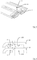
- the fastening pin 4 is incorporated into the underneath or lower side of the roof stone or tile in that it is already formed into the material during manufacture of the roof stone or tile by inserting the pin in advance into a negative mould which serves for forming the bulk material into the roof stone or tile.
- Figure 4 shows a perspective view of the upper side of one such negative mould F for forming a roof stone or tile in order to explain the arrangement of the fastening pin in the negative mould, by way of example by an automated fitting machine, prior to introducing the roof stone material (e.g. concrete or clay or plastics).
- the roof stone material e.g. concrete or clay or plastics
- the pin can also be screwed or pressed with form-fitting engagement afterwards into a corresponding opening in the underneath of the roof stone or tile. This can be achieved by way of example through projections in the manner of barbs on a fastening pin or through screw threads.
- the fastening pin inserted into the negative mould also typically has projections of such kind so that the fastening pin is reliably anchored with form-fitting engagement in the material once this material has hardened.
- the fastening pin can as shown in the drawings, be provided with a disc-like or plate-like expansion 8 at the transition region from the inserted section to the protruding section so that forces and moments introduced into the roof stone or tile via the fastening pin can be supported over a larger surface area on the underneath of the roof stone or tile.
- the fastening pin is preferably inserted or incorporated into the roof tile so that the section of the fastening pin protruding on the underneath of the roof stone or tile protrudes roughly perpendicular to a central plane Z of the roof stone or tile.
- the fastening pin has on the portion protruding from the underneath of the roof stone or tile at least one radial expansion 7, preferably however several such radial expansions 7 spaced out in the axial direction of the pin and each dimensioned to that they exceed the width of the associated recess 4 in the retaining clip 3 so that each of the expansions can produce a form-fitting connection with the recess.
- the distance L1 between two underneath sides 100 of two regularly stacked roof stones or roof tiles 1A, minus the thickness L2 of the roof stone or roof tile, is more than the length L3 the fixing pin 4 protrudes from the underneath side of the roof stone or roof tile.
- the recess 6 in the retaining clip 3 is as shown in Figures 2A and 2B preferably an oblong groove which extends from an open side 6a to the clip portion 5.
- This configuration enables the displacement in the longitudinal direction of the recess, and thus in the longitudinal direction of the roof stone or tile below, of the roof stone or tile fastened by means of the fastening pin 4 on the clip, even if the pin is inserted in the recess.
- Different overlapping lengths of roof stones can thereby be achieved, as shown in two different positions in Figure 1 on the left and right sides.
- the open end 6a of the recess 6 can be widened out funnel-like.
- the expansion can extend over a comparatively large section of the overall length of the recess to that the insertion of the fastening element also entails a certain centring of the roof stone.
- the thickness of the supporting arm on either side of the recess can also increase wedge-like in the longitudinal direction of the recess so that the roof stone is drawn towards the clip as the insertion depth increases.
- the recess can also be closed on both sides so that the fastening pin which is fitting therewith has to be configured so that it has radial expansions which are resilient in a certain way so that these can slide over the lateral edges of the recess when the fastening pin is pressed vertically into the recess.
- a type of detent connection is produced.
- the insertion can be facilitated in that the upper side of the clip either side of the recess is shaped funnel-like towards the recess in order to guide the fastening pins in the direction of the recess and to enable the attachment of the upper roof stone or tile even without being able to see the retaining clip below.
- Dimensions of the embodiment of the retaining clip 3 shown in Figures 2A and 2B are by way of example about 130 - 140 mm in the axial length and 40 - 50 mm as the vertical spacing between the bracket 3a and the arm 3b of the clip portion 5.
- the dimensions of the oblong groove 6 are to match the dimensions of the fastening pin and the relative installation positions of the fastening pin and retaining clip.
- Figure 3 shows a modified embodiment of a fastening pin 4' according to the invention which has the disc-like or plate-like expansion 8 already described for supporting on the underneath of the roof stone, as well as, on the portion protruding from the underneath of the roof stone or tile, a guide face 9 on a radial expansion 7 which centres the fastening pin 4' during insertion into the recess 6 in the retaining clip 3.
- the guide face 9 can be produced by way of example in the form of a conical tip (as shown) or in the form of a wedge-like tip or an inclined face.
- the shaft of the fastening pin is tapered in sections in the insert direction behind the radial expansion 7 with guide face 9 so that this tapered section 11 in the installed position comes to lie between the flanks of the groove-like recess in the retaining clip.
- a radially expanded shaft section 12 between the tapered section 11 and the plate-like expansion 8 serves to maintain a specific minimum distance between the roof stone or tile and the retaining clip.
- the width of the expanded shaft section 12 is for this purpose in particular greater than the width of the groove-like recess in the retaining clip.
- the fastening pin 4' has at the opposite end a further radial expansion 10 which as the fastening pin is embedded into the material of the roof stone or tile securely anchors the pin with form-fitting engagement therein.
- Dimensions of the embodiment of the fastening pin 4' illustrated in Figure 3 are by way of example about 18 - 20 mm in the axial length and 16 - 20 mm at the diameter of the radial disc-like or plate-like expansion 8.
- the embedding depth can be by way of example about 5 mm and the protrusion length of the pin beyond the disc-like or plate-like expansion 8 can amount to about 11 - 13 mm.
- Releasing the form-fitting connection between the fastening pin and recess on the retaining clip because by way of example a roof stone or tile is to be subsequently removed from a roofing system can be carried out in that the roof stone or tile is moved in the direction of the recess until the expansion part of the fastening pin has moved out of engagement with the recess.
- an ideal break point could also be provided on the fastening pin and/or on the retaining clip which beyond a predetermined force breaks and releases the form-fitting connection.
- the material of the retaining clip is in itself of any type wherein with regard to the strength and durability and possibility of moulding, plastics, metal or composite materials are suitable. The same applies for the fastening pin.
- the retaining clip is shown in the embodiment as a one-piece clip, this can also be made up from several parts so that different retaining clips can be used within one roofing system, namely those which only have the supporting arm with the recess, and those which have in addition to the supporting arm with the recess also a projection which is described below and which can serve as a fastening for a snow stopper.
- the first arm 3a of the retaining clip 3 can be designed so that in the installed state it projects out from the overlapping region of the overlapping roof stones or tiles 1 and has a projection which protrudes upwards beyond the upper side of the roof stone on which it rests and serves as a snow stopper.
- This projection can be moulded integral on the bracket or the arm 3a whereby if the arm 3a is formed by way of example from a flat strip-like band, it can be bent round into a triangle.
- the projection can however also be fastened as a separate element on the arm 3a, by way of example by a mechanical connection such as screws, rivets or the like, or by soldering, welding, adhesive-bonding or corresponding connecting methods.
- the height of the projection amounts by way of example to about 5 - 10 cm, wherein both the height and also the shape can be optional per se, provided the function as a snow stopper is guaranteed.
- the length of the arm 3a and the position of the projection serving as a snow stopper are preferably selected so that the pressure point lies above the roof batten 2 in order to prevent damage to the roofing elements through a load. Since snow stoppers are not required at all positions of the retaining clips, different variations of the retaining clip can be used in the case of one roofing system.
Landscapes
- Engineering & Computer Science (AREA)
- Mechanical Engineering (AREA)
- Architecture (AREA)
- Civil Engineering (AREA)
- Structural Engineering (AREA)
- Roof Covering Using Slabs Or Stiff Sheets (AREA)
Claims (11)
- Agrafe de retenue (3) pour fixer des dalles ou des tuiles (1A, 1B) qui doivent être disposées de façon chevauchante sur une sous-structure de toit (2), l'agrafe de retenue (3) étant conçue de façon à pouvoir être en prise autour d'une partie d'un lattis du toit de la sous-structure de toit (2) et une première dalle ou tuile (1A, 1B) afin de fixer la première dalle ou tuile (1A, 1B) sur la sous-structure de toit (2), l'agrafe de retenue (3) ayant une partie d'agrafe (5) pour être en prise autour de la partie dudit lattis du toit de la sous-structure de toit (2) et la première dalle ou tuile (1A, 1B), ladite partie d'agrafe comprenant un premier bras (3a) pour être en prise avec la face supérieure de la première dalle ou tuile (1A, 1B) et un deuxième bras (3b) pour être en contact avec la face inférieure du lattis du toit, ladite agrafe de retenue (3) comprenant un bras de support (3c) et une partie d'âme raccordant les premier et deuxième bras et le bras de support, ledit bras de support (3c) étant élevé, comme vu depuis le côté, sur une plan qui est défini par le premier bras,
caractérisé en ce que
ladite agrafe de retenue (3) a un évidement (6) avec lequel une broche de fixation (4) qui fait saillie du dessous d'une deuxième dalle ou tuile (1A, 1B) peut être mise en prise par adhérence de forme, afin de fixer la deuxième dalle ou tuile (1A, 1B) sur l'agrafe de retenue (3), et en ce que ledit évidement (6) est formé dans le bras de support (3c). - Agrafe de retenue (3) selon la revendication 1, les premier et deuxième bras s'étendant dans une direction depuis la partie d'âme, le bras de support s'étendant dans la direction opposée de la partie d'âme.
- Agrafe de retenue (3) selon la revendication 1 ou 2, l'évidement (6) dans l'agrafe de retenue (3) étant une rainure oblongue qui est conçue pour permettre un déplacement de la deuxième dalle ou tuile (1A, 1B) dans la direction longitudinale de la dalle ou tuile (1A, 1B) lorsque la broche de fixation (4) est insérée dans la rainure.
- Agrafe de retenue (3) selon l'une quelconque des revendications 1 à 3, l'évidement (6) dans l'agrafe de retenue (3) étant ouvert sur un côté longitudinal de l'évidement (6).
- Agrafe de retenue (3) selon la revendication 4, la largeur de l'évidement (6) dans la direction longitudinale de l'évidement (6) étant élargie vers le côté ouvert (6a).
- Agrafe de retenue (3) selon l'une quelconque des revendications 1 à 5, la partie d'agrafe (5) de l'agrafe de retenue (3) ayant un premier bras (3a) qui est conçu pour que, en position installée, il dépasse de la région de chevauchement des première et deuxième dalles ou tuiles (1A, 1B) et ayant une saillie dépassant vers le haut au-delà de la face supérieure de la première dalle ou tuile (1A, 1B) qui sert de préférence d'arrêt de neige.
- Agrafe de retenue (3) selon l'une quelconque des revendications 1 à 6, l'agrafe de retenue (3) étant formée à partir de plastique ou de métal ou d'un matériau composite.
- Système de couverture du toit avec dalles ou tuiles à disposer sur une sous-structure de toit de façon chevauchante, et agrafes de retenue selon l'une quelconque des revendications 1 à 7 pour fixer les dalles ou tuiles sur la sous-structure de toit.
- Couverture de toit, produite avec un système de couverture du toit selon la revendication 8, les dalles ou tuiles (1A, 1B) étant disposées sur une sous-structure de toit (2) de façon chevauchante, au moins une partie des dalles ou tuiles (1A, 1B) étant fixée avec les agrafes de retenue (3) sur la sous-structure de toit (2), et au moins une partie des dalles ou tuiles (1A, 1B) étant fixée avec la broche de fixation (4) sur les agrafes de retenue (3).
- Ensemble de pièces comprenant au moins une dalle ou tuile et au moins une agrafe de retenue selon l'une quelconque des revendications 1 à 7, l'au moins une agrafe de retenue étant appropriée pour fixer l'au moins une dalle ou tuile dans une couverture de toit sur une sous-structure de toit, la broche de fixation qui dépasse de la face inférieure de l'au moins une dalle ou tuile peut être mise en prise selon la forme avec l'évidement dans l'agrafe de retenue afin de fixer l'au moins une dalle ou tuile sur l'agrafe de retenue.
- Ensemble de pièces selon la revendication 10, qui comprend une pluralité de dalles ou de tuiles et une pluralité d'agrafes de retenue selon l'une quelconque des revendications 1 à 7.
Priority Applications (1)
| Application Number | Priority Date | Filing Date | Title |
|---|---|---|---|
| PL15741190T PL3172388T3 (pl) | 2014-07-24 | 2015-07-23 | Zacisk utrzymujący do systemu pokrycia dachowego z zabezpieczeniem przed siłą wiatru |
Applications Claiming Priority (2)
| Application Number | Priority Date | Filing Date | Title |
|---|---|---|---|
| DE102014011027.3A DE102014011027A1 (de) | 2014-07-24 | 2014-07-24 | Dachsteine oder Dachziegel und Halteklammern für ein Dacheindeckungssystem mit Windsogsicherung |
| PCT/EP2015/066831 WO2016012528A1 (fr) | 2014-07-24 | 2015-07-23 | Dalles de toiture ou tuiles de toiture et agrafes de retenue pour un système de toiture à protection contre la traînée du vent |
Publications (2)
| Publication Number | Publication Date |
|---|---|
| EP3172388A1 EP3172388A1 (fr) | 2017-05-31 |
| EP3172388B1 true EP3172388B1 (fr) | 2019-09-11 |
Family
ID=53718014
Family Applications (1)
| Application Number | Title | Priority Date | Filing Date |
|---|---|---|---|
| EP15741190.1A Not-in-force EP3172388B1 (fr) | 2014-07-24 | 2015-07-23 | Agrafe de retenue pour un système de toiture à protection contre la traînée du vent |
Country Status (5)
| Country | Link |
|---|---|
| EP (1) | EP3172388B1 (fr) |
| DE (1) | DE102014011027A1 (fr) |
| HU (1) | HUE046648T2 (fr) |
| PL (1) | PL3172388T3 (fr) |
| WO (1) | WO2016012528A1 (fr) |
Family Cites Families (9)
| Publication number | Priority date | Publication date | Assignee | Title |
|---|---|---|---|---|
| US1499398A (en) * | 1922-10-25 | 1924-07-01 | American Cement Tile Mfg Compa | Tile roofing |
| DE1880090U (de) * | 1963-07-17 | 1963-10-03 | Gustav Schmale Fa | Einsatzteil fuer dachpfannen od. dgl. |
| FR1482755A (fr) * | 1966-06-08 | 1967-05-26 | Perfectionnement aux tuiles | |
| DE1988761U (de) | 1968-04-30 | 1968-07-04 | Braas & Co Gmbh | Dachstein bzw. -ziegel mit sturmsicherung. |
| AU529271B2 (en) * | 1978-11-13 | 1983-06-02 | Monier Colourtile Pty. Ltd. | Roof tile fixing clip |
| DE9010257U1 (de) * | 1990-07-06 | 1990-09-13 | Kaiser, Helmut, 3508 Melsungen | Ziegeljustierklammer |
| US5337529A (en) * | 1993-07-23 | 1994-08-16 | Lutin Gregory D | Roof tile mounting system |
| DE4421098A1 (de) * | 1994-06-16 | 1995-12-21 | Wittenberg Ziegel Gmbh | Befestigungsvorrichtung für Dachziegel |
| DE202012011079U1 (de) * | 2012-07-13 | 2012-12-12 | Christoph Gruß | Windsogsicherungsmodul für Eindeckelemente |
-
2014
- 2014-07-24 DE DE102014011027.3A patent/DE102014011027A1/de not_active Withdrawn
-
2015
- 2015-07-23 PL PL15741190T patent/PL3172388T3/pl unknown
- 2015-07-23 EP EP15741190.1A patent/EP3172388B1/fr not_active Not-in-force
- 2015-07-23 WO PCT/EP2015/066831 patent/WO2016012528A1/fr active Application Filing
- 2015-07-23 HU HUE15741190A patent/HUE046648T2/hu unknown
Non-Patent Citations (1)
| Title |
|---|
| None * |
Also Published As
| Publication number | Publication date |
|---|---|
| PL3172388T3 (pl) | 2020-11-02 |
| HUE046648T2 (hu) | 2020-03-30 |
| DE102014011027A1 (de) | 2016-01-28 |
| WO2016012528A1 (fr) | 2016-01-28 |
| EP3172388A1 (fr) | 2017-05-31 |
Similar Documents
| Publication | Publication Date | Title |
|---|---|---|
| EP2959072B1 (fr) | Système de tuiles de toit | |
| US8516768B2 (en) | Masonry wall anchor and seismic wall anchoring system | |
| US10508833B2 (en) | Integrated hook and flashing for photovoltaic module installation on tile roofs | |
| US7921605B2 (en) | Roof structure with snow guard and method of installing | |
| EP3172388B1 (fr) | Agrafe de retenue pour un système de toiture à protection contre la traînée du vent | |
| EP1668199B1 (fr) | Dispositif et procede permettant de fixer un panneau d'isolation dans un mur creux | |
| EP2792808B1 (fr) | Système de formation de couverture de toit ou d'habillage mural, couverture de toit ou habillage mural, procédé de pose et fabrication d'éléments de couverture de toit ou d'habillage mural | |
| CN215483766U (zh) | 一种墙体外保温模板结构 | |
| KR102065623B1 (ko) | 개량형 멍에트러스 유닛 및 이를 이용한 벽체거푸집 구조 | |
| US7581364B2 (en) | Clip for attaching siding | |
| JP5648995B2 (ja) | 支持架台の取付構造、及び外装構造 | |
| US20060016129A1 (en) | Downspout extension retaining device | |
| EP2880225B1 (fr) | Toit ventilé et procédé de fabrication de toit ventilé | |
| CN220620739U (zh) | 一种用于瓦屋面顺水条和挂瓦条的固定机构 | |
| CN110894754A (zh) | 一种混凝土裂缝处理技术 | |
| CN217537377U (zh) | 一种保温板钉及保温板固定系统 | |
| CN108518025B (zh) | 插接结构及玻璃基光伏筒瓦固定系统 | |
| CN209179357U (zh) | 一种用于光伏组件框架的连接卡扣 | |
| EP1906500B1 (fr) | Boîtier à affleurement avec couvercle | |
| KR100797142B1 (ko) | 마루기와 측면 덮개용 착고 | |
| AU2013203212B2 (en) | A roof tile | |
| EP3263796A1 (fr) | Une tuile de toiture | |
| CN113513126A (zh) | 挂瓦条连接件及挂瓦连接组件 | |
| CA2842383A1 (fr) | Dispositif d'ancrage ameliore pour retenir un tapis anti-erosion par-dessus la couche de culture de plantes dans un ensemble de toit vert | |
| CA2755843C (fr) | Isolant pour maconnerie et connecteur de parement |
Legal Events
| Date | Code | Title | Description |
|---|---|---|---|
| STAA | Information on the status of an ep patent application or granted ep patent |
Free format text: STATUS: THE INTERNATIONAL PUBLICATION HAS BEEN MADE |
|
| PUAI | Public reference made under article 153(3) epc to a published international application that has entered the european phase |
Free format text: ORIGINAL CODE: 0009012 |
|
| STAA | Information on the status of an ep patent application or granted ep patent |
Free format text: STATUS: REQUEST FOR EXAMINATION WAS MADE |
|
| 17P | Request for examination filed |
Effective date: 20170201 |
|
| AK | Designated contracting states |
Kind code of ref document: A1 Designated state(s): AL AT BE BG CH CY CZ DE DK EE ES FI FR GB GR HR HU IE IS IT LI LT LU LV MC MK MT NL NO PL PT RO RS SE SI SK SM TR |
|
| AX | Request for extension of the european patent |
Extension state: BA ME |
|
| DAV | Request for validation of the european patent (deleted) | ||
| DAX | Request for extension of the european patent (deleted) | ||
| GRAP | Despatch of communication of intention to grant a patent |
Free format text: ORIGINAL CODE: EPIDOSNIGR1 |
|
| STAA | Information on the status of an ep patent application or granted ep patent |
Free format text: STATUS: GRANT OF PATENT IS INTENDED |
|
| INTG | Intention to grant announced |
Effective date: 20190403 |
|
| GRAS | Grant fee paid |
Free format text: ORIGINAL CODE: EPIDOSNIGR3 |
|
| GRAA | (expected) grant |
Free format text: ORIGINAL CODE: 0009210 |
|
| STAA | Information on the status of an ep patent application or granted ep patent |
Free format text: STATUS: THE PATENT HAS BEEN GRANTED |
|
| AK | Designated contracting states |
Kind code of ref document: B1 Designated state(s): AL AT BE BG CH CY CZ DE DK EE ES FI FR GB GR HR HU IE IS IT LI LT LU LV MC MK MT NL NO PL PT RO RS SE SI SK SM TR |
|
| REG | Reference to a national code |
Ref country code: GB Ref legal event code: FG4D |
|
| REG | Reference to a national code |
Ref country code: CH Ref legal event code: EP |
|
| REG | Reference to a national code |
Ref country code: AT Ref legal event code: REF Ref document number: 1178633 Country of ref document: AT Kind code of ref document: T Effective date: 20190915 |
|
| REG | Reference to a national code |
Ref country code: DE Ref legal event code: R096 Ref document number: 602015037795 Country of ref document: DE Ref country code: IE Ref legal event code: FG4D |
|
| REG | Reference to a national code |
Ref country code: NL Ref legal event code: FP |
|
| REG | Reference to a national code |
Ref country code: DE Ref legal event code: R082 Ref document number: 602015037795 Country of ref document: DE Representative=s name: MAMMEL & MASER, DE Ref country code: DE Ref legal event code: R081 Ref document number: 602015037795 Country of ref document: DE Owner name: CREATON GMBH, DE Free format text: FORMER OWNER: ETERNIT GMBH, 69126 HEIDELBERG, DE |
|
| RAP2 | Party data changed (patent owner data changed or rights of a patent transferred) |
Owner name: CREATON GMBH |
|
| REG | Reference to a national code |
Ref country code: NL Ref legal event code: PD Owner name: CREATON GMBH; DE Free format text: DETAILS ASSIGNMENT: CHANGE OF OWNER(S), ASSIGNMENT; FORMER OWNER NAME: ETERNIT GMBH Effective date: 20191129 |
|
| REG | Reference to a national code |
Ref country code: BE Ref legal event code: PD Owner name: CREATON AG; DE Free format text: DETAILS ASSIGNMENT: CHANGE OF OWNER(S), CESSION; FORMER OWNER NAME: ETERNIT GMBH Effective date: 20191105 |
|
| REG | Reference to a national code |
Ref country code: LT Ref legal event code: MG4D |
|
| PG25 | Lapsed in a contracting state [announced via postgrant information from national office to epo] |
Ref country code: BG Free format text: LAPSE BECAUSE OF FAILURE TO SUBMIT A TRANSLATION OF THE DESCRIPTION OR TO PAY THE FEE WITHIN THE PRESCRIBED TIME-LIMIT Effective date: 20191211 Ref country code: SE Free format text: LAPSE BECAUSE OF FAILURE TO SUBMIT A TRANSLATION OF THE DESCRIPTION OR TO PAY THE FEE WITHIN THE PRESCRIBED TIME-LIMIT Effective date: 20190911 Ref country code: LT Free format text: LAPSE BECAUSE OF FAILURE TO SUBMIT A TRANSLATION OF THE DESCRIPTION OR TO PAY THE FEE WITHIN THE PRESCRIBED TIME-LIMIT Effective date: 20190911 Ref country code: NO Free format text: LAPSE BECAUSE OF FAILURE TO SUBMIT A TRANSLATION OF THE DESCRIPTION OR TO PAY THE FEE WITHIN THE PRESCRIBED TIME-LIMIT Effective date: 20191211 Ref country code: FI Free format text: LAPSE BECAUSE OF FAILURE TO SUBMIT A TRANSLATION OF THE DESCRIPTION OR TO PAY THE FEE WITHIN THE PRESCRIBED TIME-LIMIT Effective date: 20190911 Ref country code: HR Free format text: LAPSE BECAUSE OF FAILURE TO SUBMIT A TRANSLATION OF THE DESCRIPTION OR TO PAY THE FEE WITHIN THE PRESCRIBED TIME-LIMIT Effective date: 20190911 |
|
| REG | Reference to a national code |
Ref country code: BE Ref legal event code: PD Owner name: CREATON GMBH; DE Free format text: DETAILS ASSIGNMENT: CHANGE OF OWNER(S), CHANGEMENT DE FORME JURIDIQUE, CORRECTION; FORMER OWNER NAME: CREATON AG Effective date: 20191204 |
|
| PG25 | Lapsed in a contracting state [announced via postgrant information from national office to epo] |
Ref country code: LV Free format text: LAPSE BECAUSE OF FAILURE TO SUBMIT A TRANSLATION OF THE DESCRIPTION OR TO PAY THE FEE WITHIN THE PRESCRIBED TIME-LIMIT Effective date: 20190911 Ref country code: AL Free format text: LAPSE BECAUSE OF FAILURE TO SUBMIT A TRANSLATION OF THE DESCRIPTION OR TO PAY THE FEE WITHIN THE PRESCRIBED TIME-LIMIT Effective date: 20190911 Ref country code: GR Free format text: LAPSE BECAUSE OF FAILURE TO SUBMIT A TRANSLATION OF THE DESCRIPTION OR TO PAY THE FEE WITHIN THE PRESCRIBED TIME-LIMIT Effective date: 20191212 Ref country code: RS Free format text: LAPSE BECAUSE OF FAILURE TO SUBMIT A TRANSLATION OF THE DESCRIPTION OR TO PAY THE FEE WITHIN THE PRESCRIBED TIME-LIMIT Effective date: 20190911 Ref country code: ES Free format text: LAPSE BECAUSE OF FAILURE TO SUBMIT A TRANSLATION OF THE DESCRIPTION OR TO PAY THE FEE WITHIN THE PRESCRIBED TIME-LIMIT Effective date: 20190911 |
|
| REG | Reference to a national code |
Ref country code: HU Ref legal event code: AG4A Ref document number: E046648 Country of ref document: HU |
|
| PG25 | Lapsed in a contracting state [announced via postgrant information from national office to epo] |
Ref country code: IT Free format text: LAPSE BECAUSE OF FAILURE TO SUBMIT A TRANSLATION OF THE DESCRIPTION OR TO PAY THE FEE WITHIN THE PRESCRIBED TIME-LIMIT Effective date: 20190911 Ref country code: EE Free format text: LAPSE BECAUSE OF FAILURE TO SUBMIT A TRANSLATION OF THE DESCRIPTION OR TO PAY THE FEE WITHIN THE PRESCRIBED TIME-LIMIT Effective date: 20190911 Ref country code: PT Free format text: LAPSE BECAUSE OF FAILURE TO SUBMIT A TRANSLATION OF THE DESCRIPTION OR TO PAY THE FEE WITHIN THE PRESCRIBED TIME-LIMIT Effective date: 20200113 Ref country code: RO Free format text: LAPSE BECAUSE OF FAILURE TO SUBMIT A TRANSLATION OF THE DESCRIPTION OR TO PAY THE FEE WITHIN THE PRESCRIBED TIME-LIMIT Effective date: 20190911 |
|
| PG25 | Lapsed in a contracting state [announced via postgrant information from national office to epo] |
Ref country code: CZ Free format text: LAPSE BECAUSE OF FAILURE TO SUBMIT A TRANSLATION OF THE DESCRIPTION OR TO PAY THE FEE WITHIN THE PRESCRIBED TIME-LIMIT Effective date: 20190911 Ref country code: IS Free format text: LAPSE BECAUSE OF FAILURE TO SUBMIT A TRANSLATION OF THE DESCRIPTION OR TO PAY THE FEE WITHIN THE PRESCRIBED TIME-LIMIT Effective date: 20200224 Ref country code: SK Free format text: LAPSE BECAUSE OF FAILURE TO SUBMIT A TRANSLATION OF THE DESCRIPTION OR TO PAY THE FEE WITHIN THE PRESCRIBED TIME-LIMIT Effective date: 20190911 Ref country code: SM Free format text: LAPSE BECAUSE OF FAILURE TO SUBMIT A TRANSLATION OF THE DESCRIPTION OR TO PAY THE FEE WITHIN THE PRESCRIBED TIME-LIMIT Effective date: 20190911 |
|
| REG | Reference to a national code |
Ref country code: DE Ref legal event code: R097 Ref document number: 602015037795 Country of ref document: DE |
|
| PLBE | No opposition filed within time limit |
Free format text: ORIGINAL CODE: 0009261 |
|
| STAA | Information on the status of an ep patent application or granted ep patent |
Free format text: STATUS: NO OPPOSITION FILED WITHIN TIME LIMIT |
|
| PG2D | Information on lapse in contracting state deleted |
Ref country code: IS |
|
| PG25 | Lapsed in a contracting state [announced via postgrant information from national office to epo] |
Ref country code: DK Free format text: LAPSE BECAUSE OF FAILURE TO SUBMIT A TRANSLATION OF THE DESCRIPTION OR TO PAY THE FEE WITHIN THE PRESCRIBED TIME-LIMIT Effective date: 20190911 Ref country code: IS Free format text: LAPSE BECAUSE OF FAILURE TO SUBMIT A TRANSLATION OF THE DESCRIPTION OR TO PAY THE FEE WITHIN THE PRESCRIBED TIME-LIMIT Effective date: 20200112 |
|
| 26N | No opposition filed |
Effective date: 20200615 |
|
| PG25 | Lapsed in a contracting state [announced via postgrant information from national office to epo] |
Ref country code: SI Free format text: LAPSE BECAUSE OF FAILURE TO SUBMIT A TRANSLATION OF THE DESCRIPTION OR TO PAY THE FEE WITHIN THE PRESCRIBED TIME-LIMIT Effective date: 20190911 |
|
| PGFP | Annual fee paid to national office [announced via postgrant information from national office to epo] |
Ref country code: NL Payment date: 20200715 Year of fee payment: 6 |
|
| PGFP | Annual fee paid to national office [announced via postgrant information from national office to epo] |
Ref country code: DE Payment date: 20200722 Year of fee payment: 6 |
|
| PGFP | Annual fee paid to national office [announced via postgrant information from national office to epo] |
Ref country code: HU Payment date: 20200719 Year of fee payment: 6 Ref country code: BE Payment date: 20200715 Year of fee payment: 6 Ref country code: AT Payment date: 20200709 Year of fee payment: 6 Ref country code: PL Payment date: 20200710 Year of fee payment: 6 |
|
| REG | Reference to a national code |
Ref country code: AT Ref legal event code: PC Ref document number: 1178633 Country of ref document: AT Kind code of ref document: T Owner name: CREATON GMBH, DE Effective date: 20201223 |
|
| PG25 | Lapsed in a contracting state [announced via postgrant information from national office to epo] |
Ref country code: MC Free format text: LAPSE BECAUSE OF FAILURE TO SUBMIT A TRANSLATION OF THE DESCRIPTION OR TO PAY THE FEE WITHIN THE PRESCRIBED TIME-LIMIT Effective date: 20190911 |
|
| REG | Reference to a national code |
Ref country code: CH Ref legal event code: PL |
|
| GBPC | Gb: european patent ceased through non-payment of renewal fee |
Effective date: 20200723 |
|
| PG25 | Lapsed in a contracting state [announced via postgrant information from national office to epo] |
Ref country code: FR Free format text: LAPSE BECAUSE OF NON-PAYMENT OF DUE FEES Effective date: 20200731 Ref country code: LU Free format text: LAPSE BECAUSE OF NON-PAYMENT OF DUE FEES Effective date: 20200723 Ref country code: LI Free format text: LAPSE BECAUSE OF NON-PAYMENT OF DUE FEES Effective date: 20200731 Ref country code: GB Free format text: LAPSE BECAUSE OF NON-PAYMENT OF DUE FEES Effective date: 20200723 Ref country code: CH Free format text: LAPSE BECAUSE OF NON-PAYMENT OF DUE FEES Effective date: 20200731 |
|
| PG25 | Lapsed in a contracting state [announced via postgrant information from national office to epo] |
Ref country code: IE Free format text: LAPSE BECAUSE OF NON-PAYMENT OF DUE FEES Effective date: 20200723 |
|
| REG | Reference to a national code |
Ref country code: DE Ref legal event code: R119 Ref document number: 602015037795 Country of ref document: DE |
|
| REG | Reference to a national code |
Ref country code: NL Ref legal event code: MM Effective date: 20210801 |
|
| REG | Reference to a national code |
Ref country code: AT Ref legal event code: MM01 Ref document number: 1178633 Country of ref document: AT Kind code of ref document: T Effective date: 20210723 |
|
| REG | Reference to a national code |
Ref country code: BE Ref legal event code: MM Effective date: 20210731 |
|
| PG25 | Lapsed in a contracting state [announced via postgrant information from national office to epo] |
Ref country code: HU Free format text: LAPSE BECAUSE OF NON-PAYMENT OF DUE FEES Effective date: 20210724 Ref country code: DE Free format text: LAPSE BECAUSE OF NON-PAYMENT OF DUE FEES Effective date: 20220201 Ref country code: AT Free format text: LAPSE BECAUSE OF NON-PAYMENT OF DUE FEES Effective date: 20210723 |
|
| PG25 | Lapsed in a contracting state [announced via postgrant information from national office to epo] |
Ref country code: TR Free format text: LAPSE BECAUSE OF FAILURE TO SUBMIT A TRANSLATION OF THE DESCRIPTION OR TO PAY THE FEE WITHIN THE PRESCRIBED TIME-LIMIT Effective date: 20190911 Ref country code: NL Free format text: LAPSE BECAUSE OF NON-PAYMENT OF DUE FEES Effective date: 20210801 Ref country code: MT Free format text: LAPSE BECAUSE OF FAILURE TO SUBMIT A TRANSLATION OF THE DESCRIPTION OR TO PAY THE FEE WITHIN THE PRESCRIBED TIME-LIMIT Effective date: 20190911 Ref country code: CY Free format text: LAPSE BECAUSE OF FAILURE TO SUBMIT A TRANSLATION OF THE DESCRIPTION OR TO PAY THE FEE WITHIN THE PRESCRIBED TIME-LIMIT Effective date: 20190911 |
|
| PG25 | Lapsed in a contracting state [announced via postgrant information from national office to epo] |
Ref country code: MK Free format text: LAPSE BECAUSE OF FAILURE TO SUBMIT A TRANSLATION OF THE DESCRIPTION OR TO PAY THE FEE WITHIN THE PRESCRIBED TIME-LIMIT Effective date: 20190911 |
|
| PG25 | Lapsed in a contracting state [announced via postgrant information from national office to epo] |
Ref country code: BE Free format text: LAPSE BECAUSE OF NON-PAYMENT OF DUE FEES Effective date: 20210731 |
|
| REG | Reference to a national code |
Ref country code: AT Ref legal event code: UEP Ref document number: 1178633 Country of ref document: AT Kind code of ref document: T Effective date: 20190911 |
|
| PG25 | Lapsed in a contracting state [announced via postgrant information from national office to epo] |
Ref country code: PL Free format text: LAPSE BECAUSE OF NON-PAYMENT OF DUE FEES Effective date: 20210723 |