EP3172151B1 - Subsea fluid storage unit, module, facility and method therewith - Google Patents
Subsea fluid storage unit, module, facility and method therewith Download PDFInfo
- Publication number
- EP3172151B1 EP3172151B1 EP15824979.7A EP15824979A EP3172151B1 EP 3172151 B1 EP3172151 B1 EP 3172151B1 EP 15824979 A EP15824979 A EP 15824979A EP 3172151 B1 EP3172151 B1 EP 3172151B1
- Authority
- EP
- European Patent Office
- Prior art keywords
- bladder
- fluid storage
- subsea
- vessel
- subsea fluid
- Prior art date
- Legal status (The legal status is an assumption and is not a legal conclusion. Google has not performed a legal analysis and makes no representation as to the accuracy of the status listed.)
- Active
Links
Images




Classifications
-
- B—PERFORMING OPERATIONS; TRANSPORTING
- B65—CONVEYING; PACKING; STORING; HANDLING THIN OR FILAMENTARY MATERIAL
- B65D—CONTAINERS FOR STORAGE OR TRANSPORT OF ARTICLES OR MATERIALS, e.g. BAGS, BARRELS, BOTTLES, BOXES, CANS, CARTONS, CRATES, DRUMS, JARS, TANKS, HOPPERS, FORWARDING CONTAINERS; ACCESSORIES, CLOSURES, OR FITTINGS THEREFOR; PACKAGING ELEMENTS; PACKAGES
- B65D88/00—Large containers
- B65D88/78—Large containers for use in or under water
Definitions
- the present disclosure relates to subsea fluid storage units, subsea fluid storage modules, and subsea fluid storage facilities with passive pressure compensation for subsea storage (e.g., long-term storage) of fluids.
- subsea storage e.g., long-term storage
- Subsea fluid storage systems may utilize lengthy umbilicals to transport a desired fluid.
- umbilicals may transport a desired fluid from a remote chemical supply tank to a subsea well tree.
- a remote chemical supply tank may not be unusual for a remote chemical supply tank to be 32.19 km, 80.47 km, or 128.75 km (20, 50, or 80 miles) away from the subsea well tree.
- a corresponding umbilical may also be 32.19 km, 80.47 km, or 128.75 km (20, 50, or 80 miles) long.
- the extensive length that may be required for an umbilical may present various challenges or difficulties associated with the assembling, maintaining, or repairing of the umbilical.
- umbilicals may need to withstand considerable and varying pressures within a subsea environment.
- the difficulty of identifying, locating, containing, and repairing leaks may increase as a function of umbilical length.
- the assembling, inspecting, and maintaining lengthy umbilicals may require very high costs.
- subsea storage systems may encounter various problems associated with assembly, maintenance, and/or repair.
- subsea storage systems may face extensive and constantly varying pressures (e.g., as water temperature changes). Changes in subsea pressures may result in damage to subsea storage systems, requiring frequent servicing and/or repairing, and may prevent the long-term use of subsea storage systems.
- WO 2011/084164 A1 which is regarded as closest prior art, describes the installation and removal of a vessel under water for the purpose of storing gas.
- CN 103043336 A describes an underwater oil storage tank that thermally insulates oil from water.
- US 3126559 A describes the storing of a package inside a protective bag under water.
- a first aspect of the invention relates to a subsea fluid storage unit with passive pressure compensation which comprises the features defined in claim 1.
- the present invention relates to a subsea fluid storage module according to claim 2.
- the subsea fluid storage module comprises a sub sea fluid storage unit skid, and at least one subsea fluid storage unit according to the first aspect disposed within the subsea fluid storage unit skid.
- the subsea fluid storage facility comprises a subsea platform, at least one subsea fluid storage unit skid disposed on a subsea platform, and at leas tone subsea fluid storage unit according to the first aspect disposed within the subsea fluid storage unit skid.
- Another aspect of the present disclosure relates to a method of operating a subsea fluid storage unit according to claim 4.
- the method comprises disposing a subsea fluid storage unit according to the first aspect in a subsea environment, and depositing a fluid within the bladder of the subsea fluid storage unit.
- the external bladder volume is connected to the top port of the vessel and the bladder opening is fluidically connected to the bottom port of the vessel.
- the external bladder volume is connected to the bottom port of the vessel and the bladder opening is fluidically connected to the top port of the vessel.
- a subsea fluid storage unit skid is defined, at least in part, by a plurality of I-beam segments.
- the method further comprises i) dispensing a fluid from the top port, wherein dispensing a fluid decreases the internal bladder volume, or comprises ii) receiving seawater from the bottom port, wherein the second end of the bladder is fluidically connected to the top port.
- the method further comprises i) dispensing a fluid from the bottom port, wherein dispensing a fluid decreases the internal bladder volume, or comprises ii) receiving seawater from the top port, wherein receiving seawater expands the external bladder volume, wherein the second end of a bladder is fluidically connected to the bottom port.
- Subsea fluid storage units, subsea fluid storage modules, and subsea fluid storage facilities may be completely submerged and/or located at or near ( e . g ., within a mile) a point of delivery.
- subsea fluid storage systems may comprise a plurality of subsea fluid storage modules and/or units.
- Each unit may have a standardized size and shape, for example, to promote greater ease in replacing or fitting units within a module.
- Each unit includes a vessel configured to contain one or more chemicals (e.g., chemicals in fluid form at ambient seawater temperatures).
- each unit may comprise one vessel containing a single chemical.
- Individual subsea fluid storage units may be removed and/or replaced with little to no effect on the operation of the overall system. Damage to and/or leaks in systems organized in units and modules as disclosed may be easily identified and/or repaired.
- Subsea fluid storage units may be secured or otherwise disposed within subsea fluid storage modules.
- Each unit in a module may contain any desired chemical, which may be the same or different from other unit(s) in the module.
- a module may comprise any number of units desired. For example, a module may comprise from about 1 to about 4 units.
- a module in some embodiments, may comprise any other structural or functional components desired or required for a particular application.
- a module may comprise a body onto or into which units are installed, one or more interfaces to connect (e.g., fluidically connect) each unit, and/or one or more regulators.
- a subsea storage module may comprise a body ( e.g., a platform or skid) onto or into which units are installed ( e.g., removably fixed).
- a subsea storage skid formed from a plurality of I-beam segments.
- a plurality of I-beam segments may form a rectangular frame-like structure suitable for housing a plurality of subsea fluid storage units.
- Subsea fluid storage skids or subsea fluid storage modules may be transportable over-the-road and may promote greater ease in assembling a subsea fluid storage system.
- subsea fluid storage skids or subsea fluid storage modules may be transported separately or individually prior to being deployed to a subsea environment or assembled as part of a subsea fluid storage system.
- a module may comprise an interface panel.
- An interface panel may be fluidly connected to or be in fluid communication with a plurality of subsea fluid storage units housed within a subsea fluid storage skid. Accordingly, individual subsea fluid storage units may be filled or drained through an interface panel of a subsea fluid storage skid or a subsea fluid storage module.
- An interface panel may be operated by a Remotely Operated Vehicle (ROV) configured and/or designed for subsea deployment.
- ROV Remotely Operated Vehicle
- An interface panel may also be operated at the surface by appropriate maintenance personnel.
- a module may comprise one or more mechanical and/or electronic regulators, sensors, and/or monitors.
- a module may include flow regulators (e.g., valves) and/or sensors (e.g., flow meters).
- a module may include electronic controls that permit an operator(s) ( e.g., on the sea surface) to assess and/or direct any desired metric of a unit or module's performance (e.g., flow, content, volume remaining, pressure, temperature, and/or combinations thereof).
- a unit may be filled, drained, washed, serviced, and/or otherwise operated without being removed from a subsea fluid storage skid or a subsea environment.
- Subsea fluid storage modules may be secured on or otherwise disposed on a subsea platform to form a subsea fluid storage system.
- a subsea fluid storage system may comprise a plurality of subsea platforms having a plurality of subsea fluid storage skids disposed thereon.
- a tank farm refers to a plurality of subsea platforms on which a plurality of subsea fluid storage modules are disposed.
- a tank farm or a subsea fluid storage system may comprise a control system which may monitor the pressure and fluid level of every subsea fluid storage module.
- a control system may allow for fluid isolation of any subsea fluid storage module or subsea fluid storage unit.
- FIGURES 1-7B Specific example embodiments of subsea fluid storage systems are illustrated in FIGURES 1-7B .
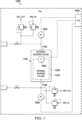
- FIGURE 1 illustrates a schematic for subsea fluid storage unit 1000.
- subsea fluid storage unit 1000 comprises vessel 1100.
- Bladder 1200 is disposed within vessel 1100.
- Bladder 1200 defines internal bladder volume 1202.
- Bladder 1200 is configured or designed to hold particular fluids or chemicals.
- Bladder 1200 is formed from deformable or collapsible material.
- internal bladder volume 1202 may vary depending on the volume or amount of fluids stored or held therein.
- Vessel 1100 comprises top port 1102 and bottom port 1106. Fluid lines may stem from each of top port 1102 and bottom port 1106. Each fluid line may have a differential pressure transducer, two pressure relief valves, and an isolation valve.
- top pressure transducer 1904 may be connected to or otherwise coupled to a fluid line in fluid communication with top port 1102.
- bottom pressure transducer 1906 may be connected to or otherwise coupled to a fluid line in fluid communication with bottom port 1106.
- Top pressure transducer 1904 and bottom pressure transducer 1906 may sense differential pressure between ambient and a fluid (e.g. seawater or stored chemical) in a fluid line to which the transducer is coupled.
- a fluid e.g. seawater or stored chemical
- Various types of pressure transducers may be used to detect a differential pressure. Such variations in a type of pressure transducers may be made without departing from the scope of the present disclosure.
- a pressure relief valve may be coupled to a fluid line of the subsea fluid storage unit 1000.
- a pressure relief valve relieves pressure, for example, by establishing a fluidic connection with a lower and/or higher pressure zone.
- a lower or higher pressure zone may be a fluid line, a separate chamber, and/or an external environment ( e.g., open water). For example, release to a lower pressure zone may relieve over-pressure.
- a relief valve may act to allow additional ambient fluid to enter the subsea fluid storage unit 1000.
- An isolation valve may be a manual ball valve which may be open during operation. In other circumstances, an isolation valve may typically be closed. For example, an isolation valve may be closed during transportation or when a subsea fluid storage unit is otherwise not installed or secured to a subsea fluid storage module.
- subsea fluid storage unit 1000 may comprise level transducer 1902.
- Level transducer 1902 may be a level sensor disposed within a subsea fluid storage unit.
- Level transducer 1902 may be coupled to bladder 1200 and may be operable to detect or sense a level of fluid in a subsea fluid storage unit.
- Subsea fluid storage unit 1000 may further comprise electrical junction box 1900.
- Electrical junction box 1900 may be disposed on and/or secured to the outside of vessel 1100. Electrical junction box 1900 may be configured to receive a variety of electrical inputs or other signals.
- subsea fluid storage unit 1000 may comprise vessel 1100 outputting signals from top pressure transducer 1904, bottom pressure transducer 1906, and level transducer 1902. Electrical junction box 1900 may receive the aforementioned signals and provide them to a processing unit of a subsea fluid storage module. In such manner, a subsea fluid storage module may be able to coordinate and control the operations of each subsea fluid storage unit 1000 to which it is coupled.
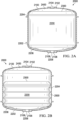
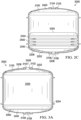
- FIGURES 2A-C illustrate section views of subsea fluid storage unit 2000 according to specific example embodiments of the disclosure.
- subsea fluid storage unit 2000 comprises vessel 2100 housing bladder 2200.
- Vessel 2100 comprises top port 2012, defining top opening 2104, and bottom port 2106, defining bottom opening 2108.
- Bladder 2200 allows for separation of a desired fluid for storage and an ambient environment fluid, i.e. seawater.
- Bladder 2200 is formed from deformable material such that internal bladder volume 2202 of bladder 2200 varies depending on the volume of content stored therein.
- Bladder 2200 may comprise various materials such as any suitable elastomers or rubbers. Particular materials used for bladder 2200 may vary depending on chemical properties of a fluid chosen for storage. Bladder 2200 may expand or contract depending on the amount of fluid or chemicals stored therein. Accordingly, internal bladder volume 2202 may increase or decrease in a similar manner as well along with a corresponding decrease in the external bladder volume.
- Bladder 2200 comprises first end 2204 and second end 2206.
- Piston 2300 is disposed adjacent to first end 2204 of bladder 2200.
- Piston 2300 is secured to first end 2204 of bladder 2200 such that any expansion, contraction, or other movement of bladder 2200 would result in a positional change of piston 2300.
- Piston 2300 may help promote or ensure predictable or consistent deformation of bladder 2200 when fluids are drained from or filled into bladder 2200.
- piston 2300 may provide a surface or physical feature on to which additional features or sensors may be secured. For example, a level transducer may be secured on piston 2300 such that the position of piston 2300 may be detected.
- Various pistons 2300 may be used without departing from the scope of the present disclosure.
- Piston 2300 is weighted or buoyant, depending on a density of a stored fluid. Piston 2300 may be configured to engage (e.g., slidably engage) a wall (e.g., an interior wall) of vessel 2100 at one or more points. For example, an interior wall of vessel 2100 may be configured to have two or more guide tracks along the height of vessel 2100, each matable with a corresponding boss or a corresponding groove on piston 2300.
- Piston 2300 may be weighted based on densities of both a stored fluid and an ambient fluid.
- Vessel 2100 may be arranged or position such that a denser fluid may be on the bottom. If a stored fluid is on bottom, piston 2300 is weighted. If a stored fluid is on top, piston 2300 is buoyant.
- a net weight and/or buoyancy of piston 2300 may be chosen to produce a desired net pressure on a stored fluid.
- a net weight and/or buoyancy may be about 0.069-0.138 bar (1-2 psi) above an ambient pressure.
- Bladder 2200 may have mechanical features to allow it to be attached to or be secured to corresponding features on the piston 2300.
- mechanical features include, but are not limited to belt loops, hooks, and/or carabiners.
- Second end 2206 of bladder 2200 comprises bladder opening 2208.
- Bladder opening 2208 may be secured to top port 2012 or bottom port 2106 of vessel 2100. In such manner, bladder opening 2208 is fluidically connected with or is in fluid communication with top opening 2102 or bottom opening 2108 of vessel 2100.
- a desired fluid such as a chemical for storage
- the other opening 2102, 2108 is in fluid communication with an ambient environment, i.e. seawater.
- an ambient environment i.e. seawater.
- another opening 2012, 2108 allows seawater to enter or exit.
- bladder 2200 comprises internal bladder volume 2202 that, in a fully expanded state, may have a substantially similar to a volume of vessel 2100 when bladder 2200 is completely full. In such manner, substantially all or most of a volume of vessel 2100 may be used to store a desired fluid within internal bladder 2202 of bladder 2200. Thus, bladder 2200 may be expanded within vessel 2100 such that there may be little or no external bladder volume 2400 left within vessel 2100.
- bladder opening 2208 is secured to bottom port 2106 of vessel 2100.
- a fluid or chemical stored within bladder 2200 may be drained from bottom port 2106 through bottom opening 2108. More specifically, a fluid or chemical stored within bladder 2200 may pass through bladder opening 2208 and bottom opening 2108. A fluid or chemical drained in such manner may then be transported or passed along via a fluid line to an intended location for particular uses.
- bladder 2200 is formed from deformable or flexible material.
- bladder 2200 may comprise materials deformable or flexible enough such that differential pressures in an ambient fluid environment would not damage bladder 2200.
- a deformable material of bladder 2200 allows bladder 2200 to collapse or contract.
- Such collapsing or contracting decreases internal bladder volume 2202 of bladder 2200.
- a decrease of internal bladder volume 2202 allows seawater, to enter vessel 2100.
- a vacuum effect may occur and drawn in ambient fluid, such as seawater, from top opening 2104. Seawater may enter vessel 2100 through top opening 2104 as defined by top port 2102.
- piston 2300 As seawater enters, greater pressure may be exerted on piston 2300 and piston 2300 may be lowered. As internal bladder volume 2202 decreases, folds or wrinkles in a material of bladder 2200 occur. Side recess volume 2500 forms along lateral portions of vessel 2100.
- FIG. 2C illustrates an embodiment as a fluid or chemical stored within bladder 2200 is further drained.
- a fluid or chemical stored within bladder 2200 may be nearly completely drained such that bladder 2200 may be nearly or entirely collapsed.
- bladder 2200 may have a very small internal bladder volume 2202. Much of the bladder 2200 material may be collected or collapsed near bottom port 2106 of vessel 2100 to which bladder opening 2208 may be secured.
- external bladder volume 2400 increases substantially as bladder 2200 is drained. An increase in external bladder volume 2400 provides additional space for the receipt of seawater. Accordingly, as internal bladder volume 2202 changes, an introduction of seawater into vessel 2100 provides for dynamic pressure compensation.
- a plurality of elastic bands may be provided around a waist of bladder 2200. Elastic bands may act to control deformation of bladder 2200. Further, elastic bands may apply a slight pressure to a fluid in bladder 2200 toward higher fill states to promote synchronized filling of a plurality of subsea fluid storage units.
- a volume within vessel 2100 that is external to bladder 2200 (e.g., an internal vessel volume) is exposed to and/or in fluid communication with an ambient seawater. Further, bladder 2200 may not resist or may provide little resistance to changes in volume. Thus, pressure within bladder 2200 may be very close to ambient pressure while subsea fluid storage unit 2000 is operating at subsea depths. Described further, a pressure differential across walls of vessel 2100 and across bladder 2200 may be very low while subsea fluid storage unit 2000 is operating at subsea depths. Exposure of external bladder volume 2400 to seawater allows for dynamic pressure compensation of subsea fluid storage unit 2000.
- Dynamic pressure compensation of subsea fluid storage unit 2000 may allow for more reliable storage units that may require less maintenance, repair, and/or other servicing.
- subsea fluid storage units 2000 of the present disclosure may be suitable for prolonged exposure in subsea environments and may provide for long term storage of fluids in subsea environments.
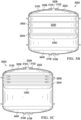
- FIGURES 3A-C illustrate section views of subsea fluid storage unit 3000 according to some example embodiments of the present disclosure.
- first end 3204 of bladder 3200 may be closer to bottom port 3106 of vessel 3100.
- piston 3300 is adjacent to and secured to first end 3204 of bladder 3200.
- piston 3300 in subsea fluid storage unit 3000 may also be closer to bottom port 3106 of vessel 3100.
- bladder opening 3208 may be secured to top port 3012 or bottom port 3106 of vessel 3100. As shown in FIG. 3A , second end 3206 of bladder 3200 may be secured to top port 3012. In the arrangement of FIG. 3A , a fluid connectivity of top port 3012 and bladder opening 3208 may allow bladder 3200 to be filled or drained via top opening 3104 as defined by top port 3012. When bladder 3200 is completely filled, internal bladder volume 3202 may occupy substantially all of the internal volume of vessel 3100.
- bladder 3200 may begin to collapse.
- a partially drained bladder 3200 comprises a reduced or lesser internal bladder volume 3202.
- a decrease of internal bladder volume 3202 allows seawater, to enter vessel 3100. Seawater enters vessel 3100 through bottom opening 3108 as defined by bottom port 3106. As seawater enters, greater pressure may be exerted on piston 3300 and piston 3300 may move to an elevated position. Alternatively, piston 3300 moves as it is secured to second end 3204 of vessel 3200. As internal bladder volume 3202 decreases, folds or wrinkles in a material of bladder 3200 occur. Side recess volume 3500 forms along lateral portions of vessel 3100.
- FIG. 3C illustrates subsea fluid storage unit 3000 when a fluid or chemical stored within bladder 3200 is further drained.
- a fluid or chemical stored within bladder 3200 may be nearly completely drained such that bladder 3200 is nearly or entirely collapsed.
- bladder 3200 may have a very small internal bladder volume 3202. Much of the bladder 3200 material may be collected or collapsed near top port 3102 of vessel 3100 to which bladder opening 3208 is secured.
- external bladder volume 3400 increases substantially as bladder 3200 is drained. An increase in external bladder volume 3400 provides additional space for the receipt of seawater. Seawater is introduced into vessel 3100 through bottom opening 3108, as defined by bottom port 3106. Accordingly, as internal bladder volume 3202 changes, an introduction of seawater into vessel 3100 provides for dynamic pressure compensation.
- disposing a fluid with a higher specific gravity at a lower position within vessel 3100 may be desired or required. Such arrangement may promote the draining of a fluid with bladder 3200 out of vessel 3100.
- a fluid desired for storage has a higher specific gravity than seawater
- a fluid desired for storage has a lower specific gravity than seawater
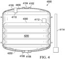
- FIGURE 4 illustrates a section view of subsea fluid storage unit 4000 according to specific example embodiments of the present disclosure.
- FIG. 4 illustrates various level transducers or level detecting sensors that may be used in conjunction with any embodiments of the present disclosure, such as the previously described embodiments.
- determining a position of piston 4300 may indicate or reveal information regarding internal bladder volume 4202 of bladder 4200. For example, as shown in FIG. 4 , a low position of piston 4300 may indicate that bladder 4200 may be substantially drained or empty. In some circumstances, this may indicate that bladder 4200 requires refilling. In contrast, a high position of piston 4300 may indicate that bladder 4200 may be substantially full.
- the present disclosure provides for various ways of determining a position of piston 4300.
- subsea fluid storage unit 4000 may comprise internal Linear Variable Differential Transformer (LVDT) 4112.
- Internal LVDT 4112 may be used in conjunction with external LVDT 4114 to determine a position of piston 4300.
- external LVDT may detect the position of a magnet or signal mounted within infernal LVDT 4112.
- LVDT Linear Variable Differential Transformer
- Various types of internal and external LVDT may be used without departing from the scope of the present disclosure.
- subsea fluid storage unit 4000 may comprise altimeter 4110 operable or configured to detect a location of piston 4300 within vessel 4100.
- Altimeter 4110 may detect a distance away from piston 4300, and such data may allow a practitioner to determine internal bladder volume 4202 of bladder 4200.
- subsea fluid storage unit 4000 may allow for determination of a position of piston 4300 via visual inspection.
- Subsea fluid storage unit 4000 may comprise a porthole or other transparent or see-through section along a portion of vessel 4100. In such manner, visual inspection may be sufficient to determine a position of piston 4300. Visual inspection may be performed topside by appropriate practitioners or may be performed remotely by a ROV deployed in a subsea environment.
- FIGURES 5A-5C illustrate perspective views of subsea fluid storage unit 5000 according to specific example embodiments of the disclosure.
- vessel 5100 may comprise handling features 5116.
- Handling features 5116 may be disposed at a base of vessel 5100.
- Handling features 5116 may comprise a plurality of segments that may be designed to mate with an instrument such as a forklift or other elevating device. In such manner, handling features 5116 may promote greater ease in transporting and/or assembling subsea fluid storage unit 5000 as part of a subsea fluid storage system.
- vessel 5100 comprises a top fluid line extending from top port 5102.
- Top vent port 5120 is disposed at a top side of vessel 5100, adjacent to top port 5102.
- Top vent port 5120 and drain port 5122 may be configured for use during topside maintenance. Top vent port 5120 may be opened during topside filling operations so that air outside a bladder may escape from vessel 5100. Drain port 5122 may be used to drain seawater or other fluids from vessel 5100.
- vessel 5100 may further comprise external bladder header 5136, internal bladder header 5134, top isolation valve 5130, bottom isolation valve 5138, top pressure relief valve 5128, and bottom pressure relief valve 5132.
- Top isolation valve 5130 and bottom isolation valve 5138 may provide isolation of fluid contents during transportation and maintenance.
- Top pressure relief valve 5128 and bottom pressure relief valve 5132 may be utilized during system overpressure and system underpressure.
- Vessel 5100 may comprise a substantially cylindrical shell and two dished and flanged tank heads. Vessel 5100 may serve to isolate the stored chemicals from an ambient environment. For example, in the event that there is a leak in a bladder, a stored chemical may leak from a bladder into vessel 5100. However, the construction of vessel 5100 may serve to isolate any chemicals from an ambient environment. Such feature may be desired or required during both transportation and subsea operations.
- Vessel 5100 may also carry loads that may exist when a system is filled with fluid and is not submerged. When vessel 5100 is not deployed in a subsea environment, pressure within vessel 5100 may not be counteracted by pressure compensation from in-flowing seawater. Accordingly, vessels 5100 of the present disclosure may be constructed so as to withstand a load from the aforementioned pressure.
- subsea fluid storage unit 5000 may comprise electronics junction box 5900.
- Electronics junction box 5900 may receive signals from various sources. For example, signals or data may be received from top pressure transducer 5904 and bottom pressure transducer 5906. Signals or data may also be received from level sensor 5908.
- Level sensor 5908 may be coupled to any of the previously mentioned features for detecting or determining a position of a piston within a vessel.
- level sensor 5908 may be an altimeter or may be coupled to an altimeter such that level sensor 5908 may relay signals or data to electronics junction box 5900 regarding a position of a piston within vessel 5100.
- Receiving signals regarding pressure or piston position at electronics junction box 5900 may allow embodiments of the present disclosure to remotely detect or determine the state of a subsea fluid storage unit 5000, such as fluid line pressures and stored fluid level.
- Vessels 5100 of the present disclosure may provide for great variety in fluid storage capacity.
- vessels 5100 may allow for fluid storage capacities of 15.90 m 3 , 794.94 m 3 , and 158.99 m 3 (100 bbl, 5000 bbl, and 1000 bbl). Any other capacities may be achieved as desired by a practitioner or as necessary for particular applications.
- Vessels 5100 may also be constructed or produced from materials suitable for subsea deployment. For example, depending on an amount of fluids or chemicals desired to be stored, dimensions for vessel 5100 may vary. Various benefits may be achieved from adjusting the size of vessel 5100. For example, a larger vessel 5100 may allow for storage of larger volumes of a particular fluid.
- a smaller vessel 5100 may allow for greater ease in the transportation and/or assembly of smaller vessel 5100. Where greater volumes of a particular fluid are needed, multiple smaller vessels 5100 may be used to store the same chemicals. Further, vessels 5100 may comprise interiors with anti-corrosive protection such that various chemicals or fluids desired for storing may be stored therein without damage to vessels 5100.
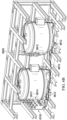
- FIGURE 6A illustrates a perspective view of a subsea fluid storage module according to a specific example embodiment of the present disclosure. As shown in FIG. 6A and FIG. 6B , subsea fluid storage units 6000 are disposed within or housed in subsea fluid storage skid 6600.
- Subsea fluid storage skid 6600 may comprise a plurality of steel I-beam frame members forming a rectangular design. Subsea fluid storage skid 6600 may comprise a plurality of removable frame members 6602 such that subsea fluid storage skid 6600 may be easily opened or disassembled in such a manner so that subsea fluid storage units 6000 may be easily or conveniently placed into subsea fluid storage skid 6600.
- ISO corners 6604 may be provided at the corners of subsea fluid storage skid 6600.
- DNV lift points 6608 may be provided at particular locations across a steel frame design of subsea fluid storage skid 6600.
- forklift handling features 6606 may be provided at a base of a subsea fluid storage skid 6600. Such features may allow forklifts or other transportation equipment to safety and securely move subsea fluid storage skid 6600, regardless of whether it is housing subsea fluid storage units 6000.
- FIG. 6A and FIG. 6B illustrate subsea fluid storage skid 6600 housing two subsea fluid storage units 6000.
- any number of subsea fluid storage units 6000 may be disposed within subsea fluid storage skid 6600.
- subsea fluid storage modules of the present disclosure may comprise any number of subsea fluid storage units 6000.
- a subsea fluids storage module comprising a larger subsea fluid storage skid 6600 may comprise three or four subsea fluid storage units 6000 housed within subsea fluid storage skid 6600.
- subsea fluid storage skid 6600 of a subsea fluid storage module comprises wiring harnesses 6610, fluid manifolds 6612, and automated valve 6614.
- Fluid lines from each subsea fluid storage units 6000 are connected to fluid manifold 6612 of a subsea fluid storage module.
- Fluid manifold 6612 may contain various valves which may allow the lines to routed appropriately.
- One fluid line from each subsea fluid storage unit 6000 may be routed to automated valve 6614.
- Other fluid lines from each subsea fluid storage unit 6000 may be routed to seawater intake valves on interface panel 6700.
- Interface panel 6700 of a subsea fluid storage module may coordinate draining and/or filling of subsea fluid storage units 6000.
- FIGURE 6C illustrates a close-up view of interface panel 6700 of a subsea fluid storage module according to a specific example embodiment of the present disclosure.
- Interface panel 6700 may be a Remotely Operated Vehicle (ROV) interface panel. Accordingly, an ROV may be deployed in a subsea environment to an interface panel and the interface panel may be remotely operated using the ROV.
- ROV Remotely Operated Vehicle
- interface panel 6700 comprises pressure gauges 6702, sea water intake 6704, wet mate connectors 6706, hot stab interface 6708, service fluid port 6710, and ROV controlled valves 6712.
- Hot stab interface 6712 may be utilized for a main fluid line, which may be routed to automated valve 6614.
- Automated valve 6614 may be controlled by an overall control system of a subsea fluid storage system. Automated valve 6614 may allow a subsea fluid storage module to be isolated from other subsea fluid storage modules during filling and draining operations. Such feature may be useful in cases where a fluid level or pressure level in subsea fluid storage unit 6000 may be higher or lower than desired.
- Service fluid port 6710 may also be connected to a main fluid line and may be used during topside filling operations.
- a ball valve may be used to close off service fluid port 6710 when it may not in use.
- Sea water intake 6704 may comprise a plurality of fluid lines routed to a corresponding port on each subsea fluid storage units 6000. In such arrangement, sea water intake 6704 may allow for free flow of sea water into and out of each subsea fluid storage units 6000.
- Subsea fluid storage units 6000 may comprise a plurality of fluid lines.
- subsea fluid storage unit 6000 may comprise two fluids lines, one stored fluid line and one seawater line. These lines may be coupled to interface panel 6700 such that each fluid line may be manually opened or closed via ROV controlled valves 6712.
- ROV controlled valves 6712 may allow for particular fluid lines to be shut off or opened during emergency situations.
- Wet mate connectors 6706 may be provided for electrical signal lines.
- An input signal may control automated valve 6614 to control fluid flow into and out of a subsea fluid storage module.
- Output signals may come from each subsea fluid storage unit 6000 for pressure and fluid level.
- Interface panel 6700 of a subsea fluid storage module may also comprise an emergency quick disconnect feature to cut off circulation and fluid communication between a subsea fluid storage module, any subsea fluid storage units 6000 contained therein, and a device that may be operably linked to interface panel 6700.
- a subsea ROV or subsea pump deployed in a subsea environment may engage interface panel 6700 to perform various tasks by operation of controls thereon and/or by establishing fluid communication with subsea fluid storage units 6000.
- An emergency quick disconnect whether operated using an ROV or remote controls on the surface or elsewhere, may cut off a fluid communication and quickly terminate ongoing operations, for example, in case of a leak or other undesired or dangerous condition.
- FIGURE 6D A schematic of a subsea fluid storage module, including some of the aforementioned features, is shown in FIGURE 6D .
- embodiments of the present disclosure allow for subsea servicing and refilling of subsea fluids storage units 6000 installed within subsea fluid storage skids 6600.
- subsea fluid storage units may be refilled using an umbilical.
- An umbilical used in conjunction with the presently disclosed subsea fluid storage units may be deployed on site (e.g., from a platform or service ship much closer to the subsea fluid storage units).
- subsea fluid storage units may be refilled in a subsea environment by, for example, the use of an ROV.
- An ROV may interface with interface panel 6700 of subsea fluid storage skid 6600.
- Manipulation of various valves on interface panel 6700 may allow an ROV to completely or partially refill or drain bladders within subsea fluid storage skids 600.
- Chemical refill may be accomplished by directly swapping out subsea fluid storage unit 6000 with another subsea fluid storage unit 6000 with a desired amount or fluid or chemical stored therein.
- a desired amount of fluid or chemical stored within a deployed subsea fluid storage unit 6000 may or may not be the same as a maximum capacity or volume or a subsea fluid storage unit 6000.
- the option and capability of subsea servicing and subsea refilling may prolong the operating life of a subsea fluid storage unit 6000, decrease the cost involved with subsea fluid storage operations, and reduce the risk associated with any leakage or damage incurred while retrieving a deployed subsea fluid storage unit 6000.
- embodiments of the present disclosure may allow for a subsea fluid storage unit 6000 to be drained in its subsea environment, and refilled with a new chemical, regardless of whether the new chemical is the same or different as a chemical previously stored in subsea fluid storage unit 6000.
- refilling of subsea fluid storage unit 6000 with a different chemical may require considerations of the chemical makeup of a bladder in subsea fluid storage unit 6000.
- it may be desired or required to bring subsea fluid storage unit 6000 topside for servicing and repurposing. Once appropriate maintenance and/or cleaning has been performed, the same subsea fluid storage unit 6000 may be used to store a different chemical.
- subsea fluid storage modules may be secured on or otherwise disposed on a subsea platform to form a subsea fluid storage system.
- subsea fluid storage modules comprise subsea fluid storage skids 7600 and subsea fluid storage units 7000 stored therein.
- Subsea fluid storage modules may then be disposed on or secured to subsea platforms 7800.
- a subsea fluid storage system may comprise a plurality of subsea platforms 7800 having a plurality of subsea fluid storage skids 7600 disposed thereon.
- a tank farm may refer to a plurality of subsea platforms 7800 on which a plurality of subsea fluid storage modules are disposed.
- a subsea fluid storage system may comprise a plurality of subsea fluid storage units 7000 that may each be at varying levels of storage capacity and may house a variety ( e.g., a wide variety) of chemicals therein.
- Each subsea fluid storage unit 7000 in a subsea fluid storage system may be individually drained and/or refilled.
- Each subsea fluid storage unit 7000 in a subsea fluid storage system may also be removed and/or replaced with another subsea fluid unit 7000 without disrupting overall operations of a subsea fluid storage system.
- the modular "plug-and-play" feature of the present disclosure may allow subsea fluid storage systems to be used or adapted for a wide variety of applications.
Landscapes
- Engineering & Computer Science (AREA)
- Mechanical Engineering (AREA)
- Filling Or Discharging Of Gas Storage Vessels (AREA)
Description
- The present disclosure relates to subsea fluid storage units, subsea fluid storage modules, and subsea fluid storage facilities with passive pressure compensation for subsea storage (e.g., long-term storage) of fluids.
- Subsea fluid storage systems may utilize lengthy umbilicals to transport a desired fluid. For example, umbilicals may transport a desired fluid from a remote chemical supply tank to a subsea well tree. In some circumstances, it may not be unusual for a remote chemical supply tank to be 32.19 km, 80.47 km, or 128.75 km (20, 50, or 80 miles) away from the subsea well tree. Thus, a corresponding umbilical may also be 32.19 km, 80.47 km, or 128.75 km (20, 50, or 80 miles) long. The extensive length that may be required for an umbilical may present various challenges or difficulties associated with the assembling, maintaining, or repairing of the umbilical. For example, umbilicals may need to withstand considerable and varying pressures within a subsea environment. The difficulty of identifying, locating, containing, and repairing leaks may increase as a function of umbilical length. Still further, the assembling, inspecting, and maintaining lengthy umbilicals may require very high costs.
- Other fluid storage systems may utilize subsea storage systems. However, subsea storage systems may encounter various problems associated with assembly, maintenance, and/or repair. For example, subsea storage systems may face extensive and constantly varying pressures (e.g., as water temperature changes). Changes in subsea pressures may result in damage to subsea storage systems, requiring frequent servicing and/or repairing, and may prevent the long-term use of subsea storage systems.
-
WO 2011/084164 A1 , which is regarded as closest prior art, describes the installation and removal of a vessel under water for the purpose of storing gas.CN 103043336 A describes an underwater oil storage tank that thermally insulates oil from water.US 3126559 A describes the storing of a package inside a protective bag under water. - Accordingly, a need has arisen for improved subsea fluid storage systems that may automatically and/or continuously compensate for subsea pressure changes, and may be convenient to refill in subsea environments or retrieve to the surface.
- The present disclosure relates to subsea fluid storage systems that automatically and/or continuously compensate for subseapressurechanges. A first aspect of the invention relates to a subsea fluid storage unit with passive pressure compensation which comprises the features defined in
claim 1. - Also, the present invention relates to a subsea fluid storage module according to
claim 2. The subsea fluid storage module comprises a sub sea fluid storage unit skid, and at least one subsea fluid storage unit according to the first aspect disposed within the subsea fluid storage unit skid. - Another aspect of the present invention relates to a subsea fluid storage facility according to claim 3. The subsea fluid storage facility comprises a subsea platform, at least one subsea fluid storage unit skid disposed on a subsea platform, and at leas tone subsea fluid storage unit according to the first aspect disposed within the subsea fluid storage unit skid.
- Another aspect of the present disclosure relates to a method of operating a subsea fluid storage unit according to claim 4. The method comprises disposing a subsea fluid storage unit according to the first aspect in a subsea environment, and depositing a fluid within the bladder of the subsea fluid storage unit.
- Preferably, the external bladder volume is connected to the top port of the vessel and the bladder opening is fluidically connected to the bottom port of the vessel. Alternatively, the external bladder volume is connected to the bottom port of the vessel and the bladder opening is fluidically connected to the top port of the vessel.
- Preferably, a subsea fluid storage unit skid is defined, at least in part, by a plurality of I-beam segments. Preferably, the method further comprises i) dispensing a fluid from the top port, wherein dispensing a fluid decreases the internal bladder volume, or comprises ii) receiving seawater from the bottom port, wherein the second end of the bladder is fluidically connected to the top port.
- Alternatively, the method further comprises i) dispensing a fluid from the bottom port, wherein dispensing a fluid decreases the internal bladder volume, or comprises ii) receiving seawater from the top port, wherein receiving seawater expands the external bladder volume, wherein the second end of a bladder is fluidically connected to the bottom port.
- Some embodiments of the disclosure may be understood by referring, in part, to the present disclosure and the accompanying drawings, wherein:
-
FIGURE 1 illustrates a schematic for a subsea fluid storage unit; -
FIGURE 2A, FIGURE 2B ,FIGURE 2C illustrate section views of a subsea fluid storage unit; -
FIGURE 3A ,FIGURE 3B, FIGURE 3C illustrate further section views of a subsea fluid storage unit; -
FIGURE 4 illustrates a further section view of a subsea fluid storage unit; -
FIGURE 5A ,FIGURE 5B ,FIGURE 5C illustrate perspective views of a subsea fluid storage unit; -
FIGURE 6A ,FIGURE 6B illustrate further perspective views of a subsea fluid storage module; -
FIGURE 6C illustrates an interface panel of a subsea fluid storage module; -
FIGURE 6D illustrates a schematic for a subsea fluid storage module; -
FIGURE 7A andFIGURE 7B illustrate perspective views of a subsea fluid storage facility. - The present disclosure relates to subsea fluid storage units, subsea fluid storage modules, and subsea fluid storage facilities with passive pressure compensation. Subsea fluid storage units, subsea fluid storage modules, and subsea fluid storage facilities may be completely submerged and/or located at or near (e.g., within a mile) a point of delivery.
- As described herein, subsea fluid storage systems may comprise a plurality of subsea fluid storage modules and/or units. Each unit may have a standardized size and shape, for example, to promote greater ease in replacing or fitting units within a module. Each unit includes a vessel configured to contain one or more chemicals (e.g., chemicals in fluid form at ambient seawater temperatures). For example, each unit may comprise one vessel containing a single chemical. Individual subsea fluid storage units may be removed and/or replaced with little to no effect on the operation of the overall system. Damage to and/or leaks in systems organized in units and modules as disclosed may be easily identified and/or repaired.
- Subsea fluid storage units may be secured or otherwise disposed within subsea fluid storage modules. Each unit in a module may contain any desired chemical, which may be the same or different from other unit(s) in the module. A module may comprise any number of units desired. For example, a module may comprise from about 1 to about 4 units. A module, in some embodiments, may comprise any other structural or functional components desired or required for a particular application. For example, a module may comprise a body onto or into which units are installed, one or more interfaces to connect (e.g., fluidically connect) each unit, and/or one or more regulators.
- A subsea storage module may comprise a body (e.g., a platform or skid) onto or into which units are installed (e.g., removably fixed). For example, a subsea storage skid formed from a plurality of I-beam segments. A plurality of I-beam segments may form a rectangular frame-like structure suitable for housing a plurality of subsea fluid storage units. Subsea fluid storage skids or subsea fluid storage modules may be transportable over-the-road and may promote greater ease in assembling a subsea fluid storage system. In some embodiments, subsea fluid storage skids or subsea fluid storage modules may be transported separately or individually prior to being deployed to a subsea environment or assembled as part of a subsea fluid storage system.
- A module may comprise an interface panel. An interface panel may be fluidly connected to or be in fluid communication with a plurality of subsea fluid storage units housed within a subsea fluid storage skid. Accordingly, individual subsea fluid storage units may be filled or drained through an interface panel of a subsea fluid storage skid or a subsea fluid storage module. An interface panel may be operated by a Remotely Operated Vehicle (ROV) configured and/or designed for subsea deployment. An interface panel may also be operated at the surface by appropriate maintenance personnel.
- A module may comprise one or more mechanical and/or electronic regulators, sensors, and/or monitors. For example, a module may include flow regulators (e.g., valves) and/or sensors (e.g., flow meters). A module may include electronic controls that permit an operator(s) (e.g., on the sea surface) to assess and/or direct any desired metric of a unit or module's performance (e.g., flow, content, volume remaining, pressure, temperature, and/or combinations thereof). A unit may be filled, drained, washed, serviced, and/or otherwise operated without being removed from a subsea fluid storage skid or a subsea environment.
- Subsea fluid storage modules may be secured on or otherwise disposed on a subsea platform to form a subsea fluid storage system. A subsea fluid storage system may comprise a plurality of subsea platforms having a plurality of subsea fluid storage skids disposed thereon. A tank farm refers to a plurality of subsea platforms on which a plurality of subsea fluid storage modules are disposed. A tank farm or a subsea fluid storage system may comprise a control system which may monitor the pressure and fluid level of every subsea fluid storage module. A control system may allow for fluid isolation of any subsea fluid storage module or subsea fluid storage unit.
- Specific example embodiments of subsea fluid storage systems are illustrated in
FIGURES 1-7B . -
FIGURE 1 illustrates a schematic for subseafluid storage unit 1000. As shown, subseafluid storage unit 1000 comprisesvessel 1100.Bladder 1200 is disposed withinvessel 1100.Bladder 1200 definesinternal bladder volume 1202.Bladder 1200 is configured or designed to hold particular fluids or chemicals.Bladder 1200 is formed from deformable or collapsible material. Thus,internal bladder volume 1202 may vary depending on the volume or amount of fluids stored or held therein. -
Vessel 1100 comprisestop port 1102 andbottom port 1106. Fluid lines may stem from each oftop port 1102 andbottom port 1106. Each fluid line may have a differential pressure transducer, two pressure relief valves, and an isolation valve. For example,top pressure transducer 1904 may be connected to or otherwise coupled to a fluid line in fluid communication withtop port 1102. Further,bottom pressure transducer 1906 may be connected to or otherwise coupled to a fluid line in fluid communication withbottom port 1106.Top pressure transducer 1904 andbottom pressure transducer 1906 may sense differential pressure between ambient and a fluid (e.g. seawater or stored chemical) in a fluid line to which the transducer is coupled. Various types of pressure transducers may be used to detect a differential pressure. Such variations in a type of pressure transducers may be made without departing from the scope of the present disclosure. - A pressure relief valve may be coupled to a fluid line of the subsea
fluid storage unit 1000. A pressure relief valve relieves pressure, for example, by establishing a fluidic connection with a lower and/or higher pressure zone. A lower or higher pressure zone may be a fluid line, a separate chamber, and/or an external environment (e.g., open water). For example, release to a lower pressure zone may relieve over-pressure. In contrast, to resolve an under-pressure condition, a relief valve may act to allow additional ambient fluid to enter the subseafluid storage unit 1000. - An isolation valve may be a manual ball valve which may be open during operation. In other circumstances, an isolation valve may typically be closed. For example, an isolation valve may be closed during transportation or when a subsea fluid storage unit is otherwise not installed or secured to a subsea fluid storage module.
- As shown in
FIG. 1 , subseafluid storage unit 1000 may compriselevel transducer 1902.Level transducer 1902 may be a level sensor disposed within a subsea fluid storage unit.Level transducer 1902 may be coupled tobladder 1200 and may be operable to detect or sense a level of fluid in a subsea fluid storage unit. - Subsea
fluid storage unit 1000 may further compriseelectrical junction box 1900.Electrical junction box 1900 may be disposed on and/or secured to the outside ofvessel 1100.Electrical junction box 1900 may be configured to receive a variety of electrical inputs or other signals. For example, in some embodiments, subseafluid storage unit 1000 may comprisevessel 1100 outputting signals fromtop pressure transducer 1904,bottom pressure transducer 1906, andlevel transducer 1902.Electrical junction box 1900 may receive the aforementioned signals and provide them to a processing unit of a subsea fluid storage module. In such manner, a subsea fluid storage module may be able to coordinate and control the operations of each subseafluid storage unit 1000 to which it is coupled. -
FIGURES 2A-C illustrate section views of subseafluid storage unit 2000 according to specific example embodiments of the disclosure. As shown inFIG. 2A , subseafluid storage unit 2000 comprisesvessel 2100housing bladder 2200.Vessel 2100 comprises top port 2012, definingtop opening 2104, and bottom port 2106, defining bottom opening 2108.Bladder 2200 allows for separation of a desired fluid for storage and an ambient environment fluid, i.e. seawater. -
Bladder 2200 is formed from deformable material such thatinternal bladder volume 2202 ofbladder 2200 varies depending on the volume of content stored therein.Bladder 2200 may comprise various materials such as any suitable elastomers or rubbers. Particular materials used forbladder 2200 may vary depending on chemical properties of a fluid chosen for storage.Bladder 2200 may expand or contract depending on the amount of fluid or chemicals stored therein. Accordingly,internal bladder volume 2202 may increase or decrease in a similar manner as well along with a corresponding decrease in the external bladder volume. -
Bladder 2200 comprisesfirst end 2204 andsecond end 2206.Piston 2300 is disposed adjacent tofirst end 2204 ofbladder 2200.Piston 2300 is secured tofirst end 2204 ofbladder 2200 such that any expansion, contraction, or other movement ofbladder 2200 would result in a positional change ofpiston 2300.Piston 2300 may help promote or ensure predictable or consistent deformation ofbladder 2200 when fluids are drained from or filled intobladder 2200. Additionally,piston 2300 may provide a surface or physical feature on to which additional features or sensors may be secured. For example, a level transducer may be secured onpiston 2300 such that the position ofpiston 2300 may be detected.Various pistons 2300 may be used without departing from the scope of the present disclosure.Piston 2300 is weighted or buoyant, depending on a density of a stored fluid.Piston 2300 may be configured to engage (e.g., slidably engage) a wall (e.g., an interior wall) ofvessel 2100 at one or more points. For example, an interior wall ofvessel 2100 may be configured to have two or more guide tracks along the height ofvessel 2100, each matable with a corresponding boss or a corresponding groove onpiston 2300. -
Piston 2300 may be weighted based on densities of both a stored fluid and an ambient fluid.Vessel 2100 may be arranged or position such that a denser fluid may be on the bottom. If a stored fluid is on bottom,piston 2300 is weighted. If a stored fluid is on top,piston 2300 is buoyant. A net weight and/or buoyancy ofpiston 2300 may be chosen to produce a desired net pressure on a stored fluid. A net weight and/or buoyancy may be about 0.069-0.138 bar (1-2 psi) above an ambient pressure. -
Bladder 2200 may have mechanical features to allow it to be attached to or be secured to corresponding features on thepiston 2300. Examples of mechanical features include, but are not limited to belt loops, hooks, and/or carabiners. -
Second end 2206 ofbladder 2200 comprisesbladder opening 2208.Bladder opening 2208 may be secured to top port 2012 or bottom port 2106 ofvessel 2100. In such manner,bladder opening 2208 is fluidically connected with or is in fluid communication withtop opening 2102 or bottom opening 2108 ofvessel 2100. Such arrangement allows a desired fluid, such as a chemical for storage, to be introduced intobladder 2200 through eithertop opening 2102 or bottom opening 2108 ofvessel 2100. Further, while oneopening 2102, 2108 is in fluid communication withbladder 2200, theother opening 2102, 2108 is in fluid communication with an ambient environment, i.e. seawater. Thus, while oneopening 2102, 2108 may allow a desired chemical for storage to enter or exit, another opening 2012, 2108 allows seawater to enter or exit. - As shown in
FIG. 2A ,bladder 2200 comprisesinternal bladder volume 2202 that, in a fully expanded state, may have a substantially similar to a volume ofvessel 2100 whenbladder 2200 is completely full. In such manner, substantially all or most of a volume ofvessel 2100 may be used to store a desired fluid withininternal bladder 2202 ofbladder 2200. Thus,bladder 2200 may be expanded withinvessel 2100 such that there may be little or noexternal bladder volume 2400 left withinvessel 2100. - As shown in
FIG. 2A ,bladder opening 2208 is secured to bottom port 2106 ofvessel 2100. Thus, a fluid or chemical stored withinbladder 2200 may be drained from bottom port 2106 through bottom opening 2108. More specifically, a fluid or chemical stored withinbladder 2200 may pass throughbladder opening 2208 and bottom opening 2108. A fluid or chemical drained in such manner may then be transported or passed along via a fluid line to an intended location for particular uses. - As shown in
FIG. 2B ,bladder 2200 is formed from deformable or flexible material. In some embodiments,bladder 2200 may comprise materials deformable or flexible enough such that differential pressures in an ambient fluid environment would not damagebladder 2200. As a fluid or chemical stored withinbladder 2200 is drained, a deformable material ofbladder 2200 allowsbladder 2200 to collapse or contract. Such collapsing or contracting decreasesinternal bladder volume 2202 ofbladder 2200. A decrease ofinternal bladder volume 2202 allows seawater, to entervessel 2100. Furthermore, asinternal bladder volume 2202 decreases, a vacuum effect may occur and drawn in ambient fluid, such as seawater, fromtop opening 2104. Seawater may entervessel 2100 throughtop opening 2104 as defined bytop port 2102. As seawater enters, greater pressure may be exerted onpiston 2300 andpiston 2300 may be lowered. Asinternal bladder volume 2202 decreases, folds or wrinkles in a material ofbladder 2200 occur.Side recess volume 2500 forms along lateral portions ofvessel 2100. -
FIG. 2C illustrates an embodiment as a fluid or chemical stored withinbladder 2200 is further drained. As shown inFIG. 2C , a fluid or chemical stored withinbladder 2200 may be nearly completely drained such thatbladder 2200 may be nearly or entirely collapsed. In this state,bladder 2200 may have a very smallinternal bladder volume 2202. Much of thebladder 2200 material may be collected or collapsed near bottom port 2106 ofvessel 2100 to whichbladder opening 2208 may be secured. As shown inFIG. 2C ,external bladder volume 2400 increases substantially asbladder 2200 is drained. An increase inexternal bladder volume 2400 provides additional space for the receipt of seawater. Accordingly, asinternal bladder volume 2202 changes, an introduction of seawater intovessel 2100 provides for dynamic pressure compensation. - A plurality of elastic bands may be provided around a waist of
bladder 2200. Elastic bands may act to control deformation ofbladder 2200. Further, elastic bands may apply a slight pressure to a fluid inbladder 2200 toward higher fill states to promote synchronized filling of a plurality of subsea fluid storage units. - A volume within
vessel 2100 that is external to bladder 2200 (e.g., an internal vessel volume) is exposed to and/or in fluid communication with an ambient seawater. Further,bladder 2200 may not resist or may provide little resistance to changes in volume. Thus, pressure withinbladder 2200 may be very close to ambient pressure while subseafluid storage unit 2000 is operating at subsea depths. Described further, a pressure differential across walls ofvessel 2100 and acrossbladder 2200 may be very low while subseafluid storage unit 2000 is operating at subsea depths. Exposure ofexternal bladder volume 2400 to seawater allows for dynamic pressure compensation of subseafluid storage unit 2000. Dynamic pressure compensation of subseafluid storage unit 2000 may allow for more reliable storage units that may require less maintenance, repair, and/or other servicing. As such, subseafluid storage units 2000 of the present disclosure may be suitable for prolonged exposure in subsea environments and may provide for long term storage of fluids in subsea environments. -
FIGURES 3A-C illustrate section views of subseafluid storage unit 3000 according to some example embodiments of the present disclosure. As shown inFIG. 3A ,first end 3204 ofbladder 3200 may be closer tobottom port 3106 ofvessel 3100. As previously described,piston 3300 is adjacent to and secured tofirst end 3204 ofbladder 3200. Thus,piston 3300 in subseafluid storage unit 3000 may also be closer tobottom port 3106 ofvessel 3100. - As previously explained,
bladder opening 3208 may be secured to top port 3012 orbottom port 3106 ofvessel 3100. As shown inFIG. 3A ,second end 3206 ofbladder 3200 may be secured to top port 3012. In the arrangement ofFIG. 3A , a fluid connectivity of top port 3012 andbladder opening 3208 may allowbladder 3200 to be filled or drained viatop opening 3104 as defined by top port 3012. Whenbladder 3200 is completely filled,internal bladder volume 3202 may occupy substantially all of the internal volume ofvessel 3100. - As a fluid is drained,
bladder 3200 may begin to collapse. As shown inFIG. 3B , a partially drainedbladder 3200 comprises a reduced or lesserinternal bladder volume 3202. A decrease ofinternal bladder volume 3202 allows seawater, to entervessel 3100. Seawater entersvessel 3100 throughbottom opening 3108 as defined bybottom port 3106. As seawater enters, greater pressure may be exerted onpiston 3300 andpiston 3300 may move to an elevated position. Alternatively,piston 3300 moves as it is secured tosecond end 3204 ofvessel 3200. Asinternal bladder volume 3202 decreases, folds or wrinkles in a material ofbladder 3200 occur.Side recess volume 3500 forms along lateral portions ofvessel 3100. -
FIG. 3C illustrates subseafluid storage unit 3000 when a fluid or chemical stored withinbladder 3200 is further drained. As shown inFIG. 3C , a fluid or chemical stored withinbladder 3200 may be nearly completely drained such thatbladder 3200 is nearly or entirely collapsed. In this state,bladder 3200 may have a very smallinternal bladder volume 3202. Much of thebladder 3200 material may be collected or collapsed neartop port 3102 ofvessel 3100 to whichbladder opening 3208 is secured. As shown inFIG. 3C ,external bladder volume 3400 increases substantially asbladder 3200 is drained. An increase inexternal bladder volume 3400 provides additional space for the receipt of seawater. Seawater is introduced intovessel 3100 throughbottom opening 3108, as defined bybottom port 3106. Accordingly, asinternal bladder volume 3202 changes, an introduction of seawater intovessel 3100 provides for dynamic pressure compensation. - In some embodiments, disposing a fluid with a higher specific gravity at a lower position within
vessel 3100 may be desired or required. Such arrangement may promote the draining of a fluid withbladder 3200 out ofvessel 3100. Thus, in embodiments where a fluid desired for storage has a higher specific gravity than seawater, it is required to configure a subsea fluid storage unit as those shown inFIG. 2A, 2B , and2C . In embodiments where a fluid desired for storage has a lower specific gravity than seawater, it is required to configure a subsea fluid storage unit as those shown inFIG. 3A ,3B, and 3C . -
FIGURE 4 illustrates a section view of subseafluid storage unit 4000 according to specific example embodiments of the present disclosure.FIG. 4 illustrates various level transducers or level detecting sensors that may be used in conjunction with any embodiments of the present disclosure, such as the previously described embodiments. - As previously described, position of
piston 4300 withinvessel 4100 varies asinternal bladder volume 4202 of thebladder 4200 varies. Thus, determining a position ofpiston 4300 may indicate or reveal information regardinginternal bladder volume 4202 ofbladder 4200. For example, as shown inFIG. 4 , a low position ofpiston 4300 may indicate thatbladder 4200 may be substantially drained or empty. In some circumstances, this may indicate thatbladder 4200 requires refilling. In contrast, a high position ofpiston 4300 may indicate thatbladder 4200 may be substantially full. The present disclosure provides for various ways of determining a position ofpiston 4300. - As shown in
FIG. 4 , subseafluid storage unit 4000 may comprise internal Linear Variable Differential Transformer (LVDT) 4112.Internal LVDT 4112 may be used in conjunction withexternal LVDT 4114 to determine a position ofpiston 4300. For example, external LVDT may detect the position of a magnet or signal mounted withininfernal LVDT 4112. Various types of internal and external LVDT may be used without departing from the scope of the present disclosure. - Additionally or alternatively, subsea
fluid storage unit 4000 may comprisealtimeter 4110 operable or configured to detect a location ofpiston 4300 withinvessel 4100.Altimeter 4110 may detect a distance away frompiston 4300, and such data may allow a practitioner to determineinternal bladder volume 4202 ofbladder 4200. - Additionally or alternatively, subsea
fluid storage unit 4000 may allow for determination of a position ofpiston 4300 via visual inspection. Subseafluid storage unit 4000 may comprise a porthole or other transparent or see-through section along a portion ofvessel 4100. In such manner, visual inspection may be sufficient to determine a position ofpiston 4300. Visual inspection may be performed topside by appropriate practitioners or may be performed remotely by a ROV deployed in a subsea environment. - Subsea fluid storage units of the present disclosure may comprise various features.
FIGURES 5A-5C illustrate perspective views of subseafluid storage unit 5000 according to specific example embodiments of the disclosure. As shown inFIG. 5A ,vessel 5100 may comprise handling features 5116. Handling features 5116 may be disposed at a base ofvessel 5100. Handling features 5116 may comprise a plurality of segments that may be designed to mate with an instrument such as a forklift or other elevating device. In such manner, handling features 5116 may promote greater ease in transporting and/or assembling subseafluid storage unit 5000 as part of a subsea fluid storage system. - As shown in
FIG. 5B ,vessel 5100 comprises a top fluid line extending fromtop port 5102.Top vent port 5120 is disposed at a top side ofvessel 5100, adjacent totop port 5102. On a bottom side ofvessel 5100, there is disposed abottom port 5106 and adrain port 5122. -
Top vent port 5120 and drainport 5122 may be configured for use during topside maintenance.Top vent port 5120 may be opened during topside filling operations so that air outside a bladder may escape fromvessel 5100.Drain port 5122 may be used to drain seawater or other fluids fromvessel 5100. - As shown in
FIG. 5C ,vessel 5100 may further compriseexternal bladder header 5136,internal bladder header 5134,top isolation valve 5130,bottom isolation valve 5138, toppressure relief valve 5128, and bottompressure relief valve 5132.Top isolation valve 5130 andbottom isolation valve 5138 may provide isolation of fluid contents during transportation and maintenance. Toppressure relief valve 5128 and bottompressure relief valve 5132 may be utilized during system overpressure and system underpressure. -
Vessel 5100 may comprise a substantially cylindrical shell and two dished and flanged tank heads.Vessel 5100 may serve to isolate the stored chemicals from an ambient environment. For example, in the event that there is a leak in a bladder, a stored chemical may leak from a bladder intovessel 5100. However, the construction ofvessel 5100 may serve to isolate any chemicals from an ambient environment. Such feature may be desired or required during both transportation and subsea operations. -
Vessel 5100 may also carry loads that may exist when a system is filled with fluid and is not submerged. Whenvessel 5100 is not deployed in a subsea environment, pressure withinvessel 5100 may not be counteracted by pressure compensation from in-flowing seawater. Accordingly,vessels 5100 of the present disclosure may be constructed so as to withstand a load from the aforementioned pressure. - Further, subsea
fluid storage unit 5000 may compriseelectronics junction box 5900.Electronics junction box 5900 may receive signals from various sources. For example, signals or data may be received fromtop pressure transducer 5904 andbottom pressure transducer 5906. Signals or data may also be received fromlevel sensor 5908.Level sensor 5908 may be coupled to any of the previously mentioned features for detecting or determining a position of a piston within a vessel. For example, in some embodiments,level sensor 5908 may be an altimeter or may be coupled to an altimeter such thatlevel sensor 5908 may relay signals or data toelectronics junction box 5900 regarding a position of a piston withinvessel 5100. Receiving signals regarding pressure or piston position atelectronics junction box 5900 may allow embodiments of the present disclosure to remotely detect or determine the state of a subseafluid storage unit 5000, such as fluid line pressures and stored fluid level. -
Vessels 5100 of the present disclosure may provide for great variety in fluid storage capacity. For example,vessels 5100 may allow for fluid storage capacities of 15.90 m3, 794.94 m3, and 158.99 m3 (100 bbl, 5000 bbl, and 1000 bbl). Any other capacities may be achieved as desired by a practitioner or as necessary for particular applications.Vessels 5100 may also be constructed or produced from materials suitable for subsea deployment. For example, depending on an amount of fluids or chemicals desired to be stored, dimensions forvessel 5100 may vary. Various benefits may be achieved from adjusting the size ofvessel 5100. For example, alarger vessel 5100 may allow for storage of larger volumes of a particular fluid. As another example, asmaller vessel 5100 may allow for greater ease in the transportation and/or assembly ofsmaller vessel 5100. Where greater volumes of a particular fluid are needed, multiplesmaller vessels 5100 may be used to store the same chemicals. Further,vessels 5100 may comprise interiors with anti-corrosive protection such that various chemicals or fluids desired for storing may be stored therein without damage tovessels 5100. - As previously described, subsea fluid storage units may be secured or otherwise disposed within subsea fluid storage modules.
FIGURE 6A illustrates a perspective view of a subsea fluid storage module according to a specific example embodiment of the present disclosure. As shown inFIG. 6A andFIG. 6B , subseafluid storage units 6000 are disposed within or housed in subseafluid storage skid 6600. - Subsea
fluid storage skid 6600 may comprise a plurality of steel I-beam frame members forming a rectangular design. Subseafluid storage skid 6600 may comprise a plurality ofremovable frame members 6602 such that subseafluid storage skid 6600 may be easily opened or disassembled in such a manner so that subseafluid storage units 6000 may be easily or conveniently placed into subseafluid storage skid 6600. - Various features may promote the transportation, deployment, or other manipulation of subsea
fluid storage skid 6600.ISO corners 6604 may be provided at the corners of subseafluid storage skid 6600. Further, DNV lift points 6608 may be provided at particular locations across a steel frame design of subseafluid storage skid 6600. Still further, forklift handling features 6606 may be provided at a base of a subseafluid storage skid 6600. Such features may allow forklifts or other transportation equipment to safety and securely move subseafluid storage skid 6600, regardless of whether it is housing subseafluid storage units 6000. -
FIG. 6A andFIG. 6B illustrate subseafluid storage skid 6600 housing two subseafluid storage units 6000. However, depending on the size of subseafluid storage skid 6600 or subseafluid storage units 6000, any number of subseafluid storage units 6000 may be disposed within subseafluid storage skid 6600. Accordingly, subsea fluid storage modules of the present disclosure may comprise any number of subseafluid storage units 6000. For example, a subsea fluids storage module comprising a larger subseafluid storage skid 6600 may comprise three or four subseafluid storage units 6000 housed within subseafluid storage skid 6600. - As shown in
FIG. 6B , subseafluid storage skid 6600 of a subsea fluid storage module comprises wiring harnesses 6610,fluid manifolds 6612, andautomated valve 6614. Fluid lines from each subseafluid storage units 6000 are connected tofluid manifold 6612 of a subsea fluid storage module.Fluid manifold 6612 may contain various valves which may allow the lines to routed appropriately. One fluid line from each subseafluid storage unit 6000 may be routed toautomated valve 6614. Other fluid lines from each subseafluid storage unit 6000 may be routed to seawater intake valves oninterface panel 6700. -
Interface panel 6700 of a subsea fluid storage module may coordinate draining and/or filling of subseafluid storage units 6000.FIGURE 6C illustrates a close-up view ofinterface panel 6700 of a subsea fluid storage module according to a specific example embodiment of the present disclosure.Interface panel 6700 may be a Remotely Operated Vehicle (ROV) interface panel. Accordingly, an ROV may be deployed in a subsea environment to an interface panel and the interface panel may be remotely operated using the ROV. - As shown in
FIG. 6C ,interface panel 6700 comprisespressure gauges 6702,sea water intake 6704,wet mate connectors 6706,hot stab interface 6708,service fluid port 6710, and ROV controlledvalves 6712.Hot stab interface 6712 may be utilized for a main fluid line, which may be routed toautomated valve 6614.Automated valve 6614 may be controlled by an overall control system of a subsea fluid storage system.Automated valve 6614 may allow a subsea fluid storage module to be isolated from other subsea fluid storage modules during filling and draining operations. Such feature may be useful in cases where a fluid level or pressure level in subseafluid storage unit 6000 may be higher or lower than desired. -
Service fluid port 6710 may also be connected to a main fluid line and may be used during topside filling operations. A ball valve may be used to close offservice fluid port 6710 when it may not in use. -
Sea water intake 6704 may comprise a plurality of fluid lines routed to a corresponding port on each subseafluid storage units 6000. In such arrangement,sea water intake 6704 may allow for free flow of sea water into and out of each subseafluid storage units 6000. - Subsea
fluid storage units 6000 may comprise a plurality of fluid lines. For example, subseafluid storage unit 6000 may comprise two fluids lines, one stored fluid line and one seawater line. These lines may be coupled tointerface panel 6700 such that each fluid line may be manually opened or closed via ROV controlledvalves 6712. ROV controlledvalves 6712 may allow for particular fluid lines to be shut off or opened during emergency situations. -
Wet mate connectors 6706 may be provided for electrical signal lines. An input signal may controlautomated valve 6614 to control fluid flow into and out of a subsea fluid storage module. Output signals may come from each subseafluid storage unit 6000 for pressure and fluid level. -
Interface panel 6700 of a subsea fluid storage module may also comprise an emergency quick disconnect feature to cut off circulation and fluid communication between a subsea fluid storage module, any subseafluid storage units 6000 contained therein, and a device that may be operably linked tointerface panel 6700. For example, a subsea ROV or subsea pump deployed in a subsea environment may engageinterface panel 6700 to perform various tasks by operation of controls thereon and/or by establishing fluid communication with subseafluid storage units 6000. An emergency quick disconnect, whether operated using an ROV or remote controls on the surface or elsewhere, may cut off a fluid communication and quickly terminate ongoing operations, for example, in case of a leak or other undesired or dangerous condition. - A schematic of a subsea fluid storage module, including some of the aforementioned features, is shown in
FIGURE 6D . Utilizing the aforementioned features, embodiments of the present disclosure allow for subsea servicing and refilling of subseafluids storage units 6000 installed within subsea fluid storage skids 6600. In some embodiments, it may be desired to bring subsea fluid storage units topside for refilling, servicing and/or repair. In some embodiments, subsea fluid storage units may be refilled using an umbilical. An umbilical used in conjunction with the presently disclosed subsea fluid storage units may be deployed on site (e.g., from a platform or service ship much closer to the subsea fluid storage units). Such locally deployed umbilicals may thus operate at significantly lower pressures. Thus, difficulties associated with higher pressures may be reduced or avoided. In some embodiments, subsea fluid storage units may be refilled in a subsea environment by, for example, the use of an ROV. An ROV may interface withinterface panel 6700 of subseafluid storage skid 6600. Manipulation of various valves oninterface panel 6700 may allow an ROV to completely or partially refill or drain bladders within subsea fluid storage skids 600. Chemical refill may be accomplished by directly swapping out subseafluid storage unit 6000 with another subseafluid storage unit 6000 with a desired amount or fluid or chemical stored therein. A desired amount of fluid or chemical stored within a deployed subseafluid storage unit 6000 may or may not be the same as a maximum capacity or volume or a subseafluid storage unit 6000. The option and capability of subsea servicing and subsea refilling may prolong the operating life of a subseafluid storage unit 6000, decrease the cost involved with subsea fluid storage operations, and reduce the risk associated with any leakage or damage incurred while retrieving a deployed subseafluid storage unit 6000. - Further, embodiments of the present disclosure may allow for a subsea
fluid storage unit 6000 to be drained in its subsea environment, and refilled with a new chemical, regardless of whether the new chemical is the same or different as a chemical previously stored in subseafluid storage unit 6000. However, refilling of subseafluid storage unit 6000 with a different chemical may require considerations of the chemical makeup of a bladder in subseafluid storage unit 6000. In some embodiments, it may be desired or required to bring subseafluid storage unit 6000 topside for servicing and repurposing. Once appropriate maintenance and/or cleaning has been performed, the same subseafluid storage unit 6000 may be used to store a different chemical. - As previously descried, subsea fluid storage modules may be secured on or otherwise disposed on a subsea platform to form a subsea fluid storage system. As shown in
FIGURE 7A-7B , subsea fluid storage modules comprise subseafluid storage skids 7600 and subseafluid storage units 7000 stored therein. Subsea fluid storage modules may then be disposed on or secured tosubsea platforms 7800. A subsea fluid storage system may comprise a plurality ofsubsea platforms 7800 having a plurality of subseafluid storage skids 7600 disposed thereon. In some embodiments, a tank farm may refer to a plurality ofsubsea platforms 7800 on which a plurality of subsea fluid storage modules are disposed. Accordingly, a subsea fluid storage system may comprise a plurality of subseafluid storage units 7000 that may each be at varying levels of storage capacity and may house a variety (e.g., a wide variety) of chemicals therein. Each subseafluid storage unit 7000 in a subsea fluid storage system may be individually drained and/or refilled. Each subseafluid storage unit 7000 in a subsea fluid storage system may also be removed and/or replaced with anothersubsea fluid unit 7000 without disrupting overall operations of a subsea fluid storage system. The modular "plug-and-play" feature of the present disclosure may allow subsea fluid storage systems to be used or adapted for a wide variety of applications.
| | | | | | | | ||
| Subsea | 1000 | 2000 | 3000 | 4000 | 5000 | 6000 | 7000 | |
| Vessel | 1100 | 2100 | 3100 | 4100 | 5100 | |||
| | 1102 | 2102 | 3102 | 4102 | 5102 | |||
| | 2104 | 3104 | 4104 | |||||
| | 1106 | 2106 | 3106 | 4106 | 5106 | |||
| Bottom opening | 2108 | 3108 | 4108 | |||||
| | 5116 | |||||||
| Vent | 5120 | |||||||
| | 5122 | |||||||
| | 5136 | |||||||
| | 5134 | |||||||
| | 5130 | |||||||
| | 5138 | |||||||
| Bottom | 5128 | |||||||
| Top | 5132 | |||||||
| | 1200 | 2200 | 3200 | 4200 | ||||
| | 1202 | 2202 | 3202 | 4202 | ||||
| | 2204 | 3204 | ||||||
| | 2206 | 3206 | ||||||
| | 2208 | 3208 | ||||||
| Piston | 2300 | 3300 | 4300 | |||||
| | 2400 | 3400 | 4400 | |||||
| | 2500 | 3500 | ||||||
| | 1900 | 5900 | 6900 | |||||
| | 1904 | 5904 | ||||||
| | 1906 | 5906 | ||||||
| | 1902 | |||||||
| | | | | | | | ||
| Internal LVDT | 4112 | |||||||
| External LVDT | 4114 | |||||||
| | 4110 | |||||||
| | 5908 | |||||||
| Subsea | 6600 | 7600 | ||||||
| | 6602 | |||||||
| ISO | 6604 | |||||||
| | 6606 | |||||||
| | 6608 | |||||||
| | 6610 | |||||||
| | 6612 | |||||||
| | 6614 | |||||||
| | 6700 | |||||||
| | 6702 | |||||||
| | 6704 | |||||||
| | 6706 | |||||||
| | 6708 | |||||||
| | 6710 | |||||||
| ROV controlled | 6712 | |||||||
| Subsea | 7800 |
Claims (8)
- A subsea fluid storage unit (1000, 2000, 3000, 4000, 5000, 6000, 7000) with passive pressure compensation, the subsea fluid storage unit comprising:a vessel (1100, 2100, 3100, 4100, 5100), the vessel comprising a top port (1102, 2102, 3102, 4102, 5102), a bottom port (1106, 2106, 3106, 4106, 5106), and an internal vessel volume;a deformable bladder (1200, 2200, 3200, 4200) disposed within the vessel, the bladder i) comprising a first end (2204, 3204) and a second end (2206, 3206), the second end having a bladder opening (2208, 3208) that is fluidically connected to the top port (1102,2102,3102,4102, 5102)orthe bottom port (1106,2106,3106, 4106, 5106) of the vessel, and ii) defining an internal bladder volume (1202, 2202, 3202, 4202), the deformable bladder (1200, 2200, 3200, 4200) being formed from deformable or collapsible material having the internal bladder volume varied depending on the volume of fluid stored therein, wherein, in use, as the internal bladder volume decreases folds of wrinkles occur in the bladder material and a side recess volume (2500, 3500) forms between the deformable bladder (1200, 2200, 3200, 4200) and lateral portions of the vessel;a piston (2300, 3300, 4300) disposed within the vessel (1100, 2100, 3100, 4100, 5100), adjacent to the first end (2204, 3204) of the bladder, the piston being secured to the first end (2204, 3204) of the bladder;the vessel (1100, 2100, 3100, 4100, 5100)further comprising an external bladder volume (2400, 3400, 4400), the external bladder volume being the internal vessel volume external to the bladder (1200, 2200,3200,4200), the external bladder volume being connected to a top opening (2104, 3104, 4104) as defined by the top port (1102, 2102, 3102, 4102, 5102), which, in use, is in fluid communication with ambient seawater, or the external bladder volume being connected to a bottom opening (2108, 3108, 4108) as defined by the bottom port (1106, 2106, 3106, 4106, 5106), which, in use, is in fluid communication with ambient seawater, the vessel having the external bladder volume (2400, 3400, 4400) varied depending on the amount of seawater stored therein; anda position of the piston (2300, 3300, 4300) being varied and defined by the internal bladder volume (1202, 2202, 3202,4202) of the bladder, the position of the piston being further defined by the amount of seawater stored in the external bladder volume (2400, 3400, 4400),wherein the external bladder volume (2400, 3400, 4400) is connected to the top port (1102, 2102, 3102, 4102, 5102) of the vessel and the bladder opening (2208, 3208) is fluidically connected to the bottom port (1106, 2106, 3106, 4106, 5106) of the vessel, when the fluid to be stored in the deformable bladder (1200, 2200, 3200, 4200) has a higher specific gravity than the seawater, and wherein the piston (2300, 3300, 4300)is positioned between thebladder(1200, 2200, 3200, 4200) and the top port (1102, 2102,3102, 4102, 5102) of the vessel, the piston (2300, 3300, 4300) being weighted to produce a desired net pressure on the fluid, orwherein the external bladder volume (2400, 3400, 4400) is connected to the bottom port (1106, 2106, 3106, 4106, 5106) of the vessel and the bladder opening (2208, 3208) is fluidically connected to the top port(1102, 2102, 3102, 4102, 5102) of the vessel, when the fluid to be stored in the deformable bladder has a lower specific gravity than the seawater, and wherein the piston (2300, 3300, 4300) is positioned between the bladder (1200, 2200, 3200, 4200) and the bottom port (1106, 2106, 3106, 4106, 5106) of the vessel, the piston (2300, 3300, 4300)being buoyant to produce a desired net pressure on the fluid.
- A subsea fluid storage module, the subsea fluid storage module comprising:a subsea fluid storage unit skid (6600, 7600); andat least one subsea fluid storage unit (1000, 2000, 3000, 4000, 5000, 6000, 7000) according to claim 1 disposed within the subsea fluid storage unit skid.
- A subsea fluid storage facility, the subsea fluid storage facility comprising:a subsea platform (7800);at least one subsea fluid storage unit skid (6600, 7600) disposed on the subsea platform; andat least one subsea fluid storage unit (1000, 2000, 3000, 4000, 5000, 6000, 7000) according to claim 1 disposed within the subsea fluid storage unit skid.
- A method of operating a subsea fluid storage unit(1000, 2000, 3000, 4000, 5000, 6000, 7000), the method comprising:disposing a subsea fluid storage unit (1000, 2000, 3000, 4000, 5000, 6000, 7000) according to claim 1 in a subsea environment,depositing a fluid within the bladder (1200, 2200, 3200, 4200) of the subsea fluid storage unit (1000, 2000, 3000, 4000, 5000, 6000, 7000).
- The subsea fluid storage unit of claim 1, or the subsea fluid storage module of claim 2, or the subsea fluid storage facility of claim 3, or the method of claim 4, wherein the piston defines an upper chamber and lower chamber within the vessel.
- The subsea fluid storage module of claim 2, or the subsea fluid storage facility of claim 3, wherein the subsea fluid storage unit skid is defined, at least in part, by a plurality of I-beam segments.
- The method of claim 4, the method further comprising: i) dispensing the fluid from the top port (1102, 2102, 3102, 4102, 5102), wherein dispensing the fluid decreases the internal bladder volume; or ii) receiving the seawater from the bottom port (1106, 2106, 3106,4106, 5106), wherein receiving the seawater expands the external bladder volume, wherein the second end (2206, 3206) of the bladder is fluidically connected to the top port (1102, 2102, 3102, 4102, 5102).
- The method of claim 4, the method further comprising: i) dispensing the fluid from the bottom port (1106, 2106, 3106, 4106, 5106), wherein dispensing the fluid decreases the internal bladder volume; or ii) receiving the seawater from the top port (1102, 2102, 3102,4102, 5102), wherein receiving the seawater expands the external bladder volume, wherein the second end (2206, 3206) of the bladder is fluidically connected to the bottom port (1106, 2106, 3106, 4106, 5106).
Applications Claiming Priority (2)
| Application Number | Priority Date | Filing Date | Title |
|---|---|---|---|
| US14/340,383 US9656800B2 (en) | 2014-07-24 | 2014-07-24 | Subsea fluid storage system |
| PCT/US2015/041812 WO2016014841A1 (en) | 2014-07-24 | 2015-07-23 | Subsea fluid storage system |
Publications (3)
| Publication Number | Publication Date |
|---|---|
| EP3172151A1 EP3172151A1 (en) | 2017-05-31 |
| EP3172151A4 EP3172151A4 (en) | 2018-09-05 |
| EP3172151B1 true EP3172151B1 (en) | 2023-11-22 |
Family
ID=55163786
Family Applications (1)
| Application Number | Title | Priority Date | Filing Date |
|---|---|---|---|
| EP15824979.7A Active EP3172151B1 (en) | 2014-07-24 | 2015-07-23 | Subsea fluid storage unit, module, facility and method therewith |
Country Status (3)
| Country | Link |
|---|---|
| US (1) | US9656800B2 (en) |
| EP (1) | EP3172151B1 (en) |
| WO (1) | WO2016014841A1 (en) |
Families Citing this family (15)
| Publication number | Priority date | Publication date | Assignee | Title |
|---|---|---|---|---|
| US9470365B1 (en) * | 2015-07-13 | 2016-10-18 | Chevron U.S.A. Inc. | Apparatus, methods, and systems for storing and managing liquids in an offshore environment |
| US9783947B2 (en) * | 2015-12-27 | 2017-10-10 | William Wei Lee | Submerged oil storage, loading and offloading system |
| US10193269B2 (en) * | 2016-05-27 | 2019-01-29 | Oceaneering International, Inc. | Connector maintenance panel |
| US10405459B2 (en) * | 2016-08-04 | 2019-09-03 | Hamilton Sundstrand Corporation | Actuated immersion cooled electronic assemblies |
| US10370186B2 (en) * | 2016-09-13 | 2019-08-06 | Oceaneering International, Inc. | Subsea fluid storage system |
| CN206827385U (en) | 2017-06-12 | 2018-01-02 | 上海杰碧管道工程有限公司 | A kind of high-performance seabed flexibility oil storage system |
| GB2588326B (en) * | 2018-07-09 | 2021-11-10 | Subsea 7 Norway As | Assembly and maintenance of subsea fluid storage units |
| GB2575453B (en) * | 2018-07-09 | 2021-01-20 | Subsea 7 Norway As | Subsea Fluid Storage Unit |
| IT201900001687A1 (en) | 2019-02-06 | 2020-08-06 | Sandro Matterazzo | OVERPRESSURE PROTECTION SYSTEM FOR UNDERWATER TANKS |
| MX2021013915A (en) * | 2019-05-16 | 2023-02-28 | David C Wright | Subsea duplex pump, subsea pumping system, and subsea pumping method. |
| CN115023533A (en) * | 2019-11-11 | 2022-09-06 | J.雷.麦克德莫特股份有限公司 | Destructive coupling system and method for subsea systems |
| GB2602115B (en) | 2020-12-18 | 2023-07-12 | Subsea 7 Norway As | Storage of fluids underwater |
| NO347964B1 (en) * | 2020-12-18 | 2024-06-03 | Subsea 7 Norway As | Storage of fluids underwater |
| AU2022224960B2 (en) * | 2021-02-26 | 2025-05-08 | Grant Prideco, Inc. | Subsea storage of a water miscible storage fluid |
| KR20230156119A (en) * | 2021-03-12 | 2023-11-13 | 마카이 오션 엔지니어링, 인크. | Subsea Anchorage Installation System |
Citations (1)
| Publication number | Priority date | Publication date | Assignee | Title |
|---|---|---|---|---|
| WO2008014203A1 (en) * | 2006-07-26 | 2008-01-31 | Bp Corporation North America Inc. | Multi-product tank |
Family Cites Families (24)
| Publication number | Priority date | Publication date | Assignee | Title |
|---|---|---|---|---|
| US3126559A (en) * | 1964-03-31 | Sensor | ||
| US2947437A (en) * | 1957-04-23 | 1960-08-02 | David M Greer | Storage tanks for liquids |
| US3695047A (en) * | 1970-07-02 | 1972-10-03 | Texaco Inc | Underwater liquid storage facility |
| US4480569A (en) * | 1983-01-12 | 1984-11-06 | Veen Abraham V D | Container for ground material removed by a ground working device from the bottom of a watercourse |
| US4662386A (en) | 1986-04-03 | 1987-05-05 | Sofec, Inc. | Subsea petroleum products storage system |
| US5234191A (en) * | 1986-12-01 | 1993-08-10 | Convault, Inc. | Apparatus for forming a fluid containment vault |
| US5082138A (en) * | 1990-04-16 | 1992-01-21 | Lrs, Inc. | Fire resistant tank construction |
| US5235928A (en) | 1992-09-30 | 1993-08-17 | The United States Of America As Represented By The Secretary Of The Navy | Towed submergible, collapsible, steerable tank |
| US6514009B2 (en) * | 1998-12-01 | 2003-02-04 | Robert William Northcott | Subterranean storage vessel system |
| US6739274B2 (en) * | 2001-04-11 | 2004-05-25 | Albany International Corp. | End portions for a flexible fluid containment vessel and a method of making the same |
| US7270907B2 (en) * | 2002-01-08 | 2007-09-18 | Procter & Gamble Company | Fuel container and delivery apparatus for a liquid feed fuel cell system |
| GB2393426B (en) * | 2002-09-28 | 2007-06-06 | Cooper Cameron Corp | Underwater enclosure apparatus and method for constructing the same |
| NO322872B1 (en) * | 2003-11-13 | 2006-12-18 | Aker Marine Contractors As | Vertical installation of an elongated process unit |
| AU2008216285B2 (en) * | 2007-02-12 | 2011-07-28 | Valkyrie Commissioning Services, Inc. | Subsea pipeline service skid |
| GB0711930D0 (en) * | 2007-06-20 | 2007-08-01 | Acergy France Sa | Pipeline connection apparatus and method |
| US7500442B1 (en) | 2008-01-11 | 2009-03-10 | Schanz Ii, Llc | Submerged transporter and storage system for liquids and solids |
| NO329945B1 (en) * | 2008-10-10 | 2010-12-27 | Tool Tech As | Process for preparing an acid-proof, seamless pressure vessel |
| US7841289B1 (en) * | 2009-10-22 | 2010-11-30 | Schanz Richard W | Water level and/or sub surface water transporter/storage systems for liquids and solids simultaneously or in single cargo |
| US9435185B2 (en) * | 2009-12-24 | 2016-09-06 | Wright's Well Control Services, Llc | Subsea technique for promoting fluid flow |
| US20120260839A1 (en) * | 2010-01-05 | 2012-10-18 | Horton Wison Deepwater, Inc. | Systems and methods for subsea gas storage installation and removal |
| CN103210178A (en) | 2010-10-12 | 2013-07-17 | Bp北美公司 | Subsea autonomous dispersant injection system and methods |
| NO20101793A1 (en) | 2010-12-21 | 2012-01-16 | Seabox As | Technical system, method and applications for dosing at least one liquid treatment agent in injection water to an injection well |
| US8905677B2 (en) | 2012-11-15 | 2014-12-09 | Fluor Technologies Corporation | Subsea fluid storage system and methods therefor |
| CN103043336B (en) * | 2013-01-04 | 2013-11-13 | 中国石油大学(华东) | Oil-water isolated underwater oil storage tank |
-
2014
- 2014-07-24 US US14/340,383 patent/US9656800B2/en active Active
-
2015
- 2015-07-23 EP EP15824979.7A patent/EP3172151B1/en active Active
- 2015-07-23 WO PCT/US2015/041812 patent/WO2016014841A1/en not_active Ceased
Patent Citations (1)
| Publication number | Priority date | Publication date | Assignee | Title |
|---|---|---|---|---|
| WO2008014203A1 (en) * | 2006-07-26 | 2008-01-31 | Bp Corporation North America Inc. | Multi-product tank |
Also Published As
| Publication number | Publication date |
|---|---|
| US9656800B2 (en) | 2017-05-23 |
| EP3172151A1 (en) | 2017-05-31 |
| WO2016014841A1 (en) | 2016-01-28 |
| EP3172151A4 (en) | 2018-09-05 |
| US20160023843A1 (en) | 2016-01-28 |
Similar Documents
| Publication | Publication Date | Title |
|---|---|---|
| US9656800B2 (en) | Subsea fluid storage system | |
| AU2020203153B2 (en) | Subsea storage tank, method of installing and recovering such a tank, system, method to retrofit a storage tank and method of refilling a subsea storage tank | |
| US9079639B2 (en) | Large volume subsea chemical storage and metering system | |
| EP1985535B1 (en) | Cargo pump apparatus for liquid cargo ship | |
| EP2981455B1 (en) | Large subsea package deployment methods and devices | |
| CN105570665B (en) | Filling tank system peculiar to vessel and the LNG filling landing stage with the tank system | |
| AU2019300069A1 (en) | Subsea fluid storage unit | |
| GB2499804A (en) | Collapsible fluid receptacle weighted to overcome buoyancy of contents | |
| CN119866298A (en) | Method and apparatus for buoyancy tanks for deep sea mining | |
| TW201811619A (en) | Method for assembling a transport tank in a vessel and a corresponding vessel | |
| US20240051740A1 (en) | Storage of Fluids Underwater | |
| EP3653535A1 (en) | Subsea storage tank | |
| US20210300176A1 (en) | Fuel Tank with Internal Bladder and Method | |
| WO2016207359A2 (en) | Meg storage system and a method for deployment and operation of meg storage system | |
| US4090366A (en) | Transit capsules | |
| KR20150063752A (en) | Pressure Vessel and Test Apparatus for Drilling Equipment Using The Same | |
| US20230182996A1 (en) | Storage Tank, Transport System Therewith and Method for Operating It | |
| NO347964B1 (en) | Storage of fluids underwater | |
| GB2529311A (en) | Submersible fluid storage |
Legal Events
| Date | Code | Title | Description |
|---|---|---|---|
| STAA | Information on the status of an ep patent application or granted ep patent |
Free format text: STATUS: THE INTERNATIONAL PUBLICATION HAS BEEN MADE |
|
| PUAI | Public reference made under article 153(3) epc to a published international application that has entered the european phase |
Free format text: ORIGINAL CODE: 0009012 |
|
| STAA | Information on the status of an ep patent application or granted ep patent |
Free format text: STATUS: REQUEST FOR EXAMINATION WAS MADE |
|
| 17P | Request for examination filed |
Effective date: 20170224 |
|
| AK | Designated contracting states |
Kind code of ref document: A1 Designated state(s): AL AT BE BG CH CY CZ DE DK EE ES FI FR GB GR HR HU IE IS IT LI LT LU LV MC MK MT NL NO PL PT RO RS SE SI SK SM TR |
|
| AX | Request for extension of the european patent |
Extension state: BA ME |
|
| DAV | Request for validation of the european patent (deleted) | ||
| DAX | Request for extension of the european patent (deleted) | ||
| A4 | Supplementary search report drawn up and despatched |
Effective date: 20180803 |
|
| RIC1 | Information provided on ipc code assigned before grant |
Ipc: B65D 88/78 20060101AFI20180730BHEP |
|
| STAA | Information on the status of an ep patent application or granted ep patent |
Free format text: STATUS: EXAMINATION IS IN PROGRESS |
|
| 17Q | First examination report despatched |
Effective date: 20190822 |
|
| TPAC | Observations filed by third parties |
Free format text: ORIGINAL CODE: EPIDOSNTIPA |
|
| GRAP | Despatch of communication of intention to grant a patent |
Free format text: ORIGINAL CODE: EPIDOSNIGR1 |
|
| STAA | Information on the status of an ep patent application or granted ep patent |
Free format text: STATUS: GRANT OF PATENT IS INTENDED |
|
| INTG | Intention to grant announced |
Effective date: 20230607 |
|
| GRAS | Grant fee paid |
Free format text: ORIGINAL CODE: EPIDOSNIGR3 |
|
| GRAA | (expected) grant |
Free format text: ORIGINAL CODE: 0009210 |
|
| STAA | Information on the status of an ep patent application or granted ep patent |
Free format text: STATUS: THE PATENT HAS BEEN GRANTED |
|
| AK | Designated contracting states |
Kind code of ref document: B1 Designated state(s): AL AT BE BG CH CY CZ DE DK EE ES FI FR GB GR HR HU IE IS IT LI LT LU LV MC MK MT NL NO PL PT RO RS SE SI SK SM TR |
|
| REG | Reference to a national code |
Ref country code: GB Ref legal event code: FG4D |
|
| REG | Reference to a national code |
Ref country code: CH Ref legal event code: EP |
|
| REG | Reference to a national code |
Ref country code: DE Ref legal event code: R096 Ref document number: 602015086661 Country of ref document: DE |
|
| REG | Reference to a national code |
Ref country code: IE Ref legal event code: FG4D |
|
| REG | Reference to a national code |
Ref country code: LT Ref legal event code: MG9D |
|
| REG | Reference to a national code |
Ref country code: NL Ref legal event code: MP Effective date: 20231122 |
|
| PG25 | Lapsed in a contracting state [announced via postgrant information from national office to epo] |
Ref country code: GR Free format text: LAPSE BECAUSE OF FAILURE TO SUBMIT A TRANSLATION OF THE DESCRIPTION OR TO PAY THE FEE WITHIN THE PRESCRIBED TIME-LIMIT Effective date: 20240223 |
|
| PG25 | Lapsed in a contracting state [announced via postgrant information from national office to epo] |
Ref country code: IS Free format text: LAPSE BECAUSE OF FAILURE TO SUBMIT A TRANSLATION OF THE DESCRIPTION OR TO PAY THE FEE WITHIN THE PRESCRIBED TIME-LIMIT Effective date: 20240322 |
|
| PG25 | Lapsed in a contracting state [announced via postgrant information from national office to epo] |
Ref country code: LT Free format text: LAPSE BECAUSE OF FAILURE TO SUBMIT A TRANSLATION OF THE DESCRIPTION OR TO PAY THE FEE WITHIN THE PRESCRIBED TIME-LIMIT Effective date: 20231122 |
|
| REG | Reference to a national code |
Ref country code: AT Ref legal event code: MK05 Ref document number: 1633645 Country of ref document: AT Kind code of ref document: T Effective date: 20231122 |
|
| PG25 | Lapsed in a contracting state [announced via postgrant information from national office to epo] |
Ref country code: NL Free format text: LAPSE BECAUSE OF FAILURE TO SUBMIT A TRANSLATION OF THE DESCRIPTION OR TO PAY THE FEE WITHIN THE PRESCRIBED TIME-LIMIT Effective date: 20231122 |
|
| PG25 | Lapsed in a contracting state [announced via postgrant information from national office to epo] |
Ref country code: AT Free format text: LAPSE BECAUSE OF FAILURE TO SUBMIT A TRANSLATION OF THE DESCRIPTION OR TO PAY THE FEE WITHIN THE PRESCRIBED TIME-LIMIT Effective date: 20231122 |
|
| PG25 | Lapsed in a contracting state [announced via postgrant information from national office to epo] |
Ref country code: ES Free format text: LAPSE BECAUSE OF FAILURE TO SUBMIT A TRANSLATION OF THE DESCRIPTION OR TO PAY THE FEE WITHIN THE PRESCRIBED TIME-LIMIT Effective date: 20231122 |
|
| PG25 | Lapsed in a contracting state [announced via postgrant information from national office to epo] |
Ref country code: NL Free format text: LAPSE BECAUSE OF FAILURE TO SUBMIT A TRANSLATION OF THE DESCRIPTION OR TO PAY THE FEE WITHIN THE PRESCRIBED TIME-LIMIT Effective date: 20231122 Ref country code: LT Free format text: LAPSE BECAUSE OF FAILURE TO SUBMIT A TRANSLATION OF THE DESCRIPTION OR TO PAY THE FEE WITHIN THE PRESCRIBED TIME-LIMIT Effective date: 20231122 Ref country code: IS Free format text: LAPSE BECAUSE OF FAILURE TO SUBMIT A TRANSLATION OF THE DESCRIPTION OR TO PAY THE FEE WITHIN THE PRESCRIBED TIME-LIMIT Effective date: 20240322 Ref country code: GR Free format text: LAPSE BECAUSE OF FAILURE TO SUBMIT A TRANSLATION OF THE DESCRIPTION OR TO PAY THE FEE WITHIN THE PRESCRIBED TIME-LIMIT Effective date: 20240223 Ref country code: ES Free format text: LAPSE BECAUSE OF FAILURE TO SUBMIT A TRANSLATION OF THE DESCRIPTION OR TO PAY THE FEE WITHIN THE PRESCRIBED TIME-LIMIT Effective date: 20231122 Ref country code: BG Free format text: LAPSE BECAUSE OF FAILURE TO SUBMIT A TRANSLATION OF THE DESCRIPTION OR TO PAY THE FEE WITHIN THE PRESCRIBED TIME-LIMIT Effective date: 20240222 Ref country code: AT Free format text: LAPSE BECAUSE OF FAILURE TO SUBMIT A TRANSLATION OF THE DESCRIPTION OR TO PAY THE FEE WITHIN THE PRESCRIBED TIME-LIMIT Effective date: 20231122 Ref country code: PT Free format text: LAPSE BECAUSE OF FAILURE TO SUBMIT A TRANSLATION OF THE DESCRIPTION OR TO PAY THE FEE WITHIN THE PRESCRIBED TIME-LIMIT Effective date: 20240322 |
|
| PG25 | Lapsed in a contracting state [announced via postgrant information from national office to epo] |
Ref country code: SE Free format text: LAPSE BECAUSE OF FAILURE TO SUBMIT A TRANSLATION OF THE DESCRIPTION OR TO PAY THE FEE WITHIN THE PRESCRIBED TIME-LIMIT Effective date: 20231122 Ref country code: RS Free format text: LAPSE BECAUSE OF FAILURE TO SUBMIT A TRANSLATION OF THE DESCRIPTION OR TO PAY THE FEE WITHIN THE PRESCRIBED TIME-LIMIT Effective date: 20231122 Ref country code: PL Free format text: LAPSE BECAUSE OF FAILURE TO SUBMIT A TRANSLATION OF THE DESCRIPTION OR TO PAY THE FEE WITHIN THE PRESCRIBED TIME-LIMIT Effective date: 20231122 Ref country code: LV Free format text: LAPSE BECAUSE OF FAILURE TO SUBMIT A TRANSLATION OF THE DESCRIPTION OR TO PAY THE FEE WITHIN THE PRESCRIBED TIME-LIMIT Effective date: 20231122 Ref country code: HR Free format text: LAPSE BECAUSE OF FAILURE TO SUBMIT A TRANSLATION OF THE DESCRIPTION OR TO PAY THE FEE WITHIN THE PRESCRIBED TIME-LIMIT Effective date: 20231122 |
|
| PG25 | Lapsed in a contracting state [announced via postgrant information from national office to epo] |
Ref country code: DK Free format text: LAPSE BECAUSE OF FAILURE TO SUBMIT A TRANSLATION OF THE DESCRIPTION OR TO PAY THE FEE WITHIN THE PRESCRIBED TIME-LIMIT Effective date: 20231122 |
|
| PG25 | Lapsed in a contracting state [announced via postgrant information from national office to epo] |
Ref country code: CZ Free format text: LAPSE BECAUSE OF FAILURE TO SUBMIT A TRANSLATION OF THE DESCRIPTION OR TO PAY THE FEE WITHIN THE PRESCRIBED TIME-LIMIT Effective date: 20231122 |
|
| PG25 | Lapsed in a contracting state [announced via postgrant information from national office to epo] |
Ref country code: SK Free format text: LAPSE BECAUSE OF FAILURE TO SUBMIT A TRANSLATION OF THE DESCRIPTION OR TO PAY THE FEE WITHIN THE PRESCRIBED TIME-LIMIT Effective date: 20231122 |
|
| PG25 | Lapsed in a contracting state [announced via postgrant information from national office to epo] |
Ref country code: SM Free format text: LAPSE BECAUSE OF FAILURE TO SUBMIT A TRANSLATION OF THE DESCRIPTION OR TO PAY THE FEE WITHIN THE PRESCRIBED TIME-LIMIT Effective date: 20231122 Ref country code: SK Free format text: LAPSE BECAUSE OF FAILURE TO SUBMIT A TRANSLATION OF THE DESCRIPTION OR TO PAY THE FEE WITHIN THE PRESCRIBED TIME-LIMIT Effective date: 20231122 Ref country code: RO Free format text: LAPSE BECAUSE OF FAILURE TO SUBMIT A TRANSLATION OF THE DESCRIPTION OR TO PAY THE FEE WITHIN THE PRESCRIBED TIME-LIMIT Effective date: 20231122 Ref country code: IT Free format text: LAPSE BECAUSE OF FAILURE TO SUBMIT A TRANSLATION OF THE DESCRIPTION OR TO PAY THE FEE WITHIN THE PRESCRIBED TIME-LIMIT Effective date: 20231122 Ref country code: EE Free format text: LAPSE BECAUSE OF FAILURE TO SUBMIT A TRANSLATION OF THE DESCRIPTION OR TO PAY THE FEE WITHIN THE PRESCRIBED TIME-LIMIT Effective date: 20231122 Ref country code: DK Free format text: LAPSE BECAUSE OF FAILURE TO SUBMIT A TRANSLATION OF THE DESCRIPTION OR TO PAY THE FEE WITHIN THE PRESCRIBED TIME-LIMIT Effective date: 20231122 Ref country code: CZ Free format text: LAPSE BECAUSE OF FAILURE TO SUBMIT A TRANSLATION OF THE DESCRIPTION OR TO PAY THE FEE WITHIN THE PRESCRIBED TIME-LIMIT Effective date: 20231122 |
|
| REG | Reference to a national code |
Ref country code: DE Ref legal event code: R097 Ref document number: 602015086661 Country of ref document: DE |
|
| PLBE | No opposition filed within time limit |
Free format text: ORIGINAL CODE: 0009261 |
|
| STAA | Information on the status of an ep patent application or granted ep patent |
Free format text: STATUS: NO OPPOSITION FILED WITHIN TIME LIMIT |
|
| PG25 | Lapsed in a contracting state [announced via postgrant information from national office to epo] |
Ref country code: SI Free format text: LAPSE BECAUSE OF FAILURE TO SUBMIT A TRANSLATION OF THE DESCRIPTION OR TO PAY THE FEE WITHIN THE PRESCRIBED TIME-LIMIT Effective date: 20231122 |
|
| 26N | No opposition filed |
Effective date: 20240823 |
|
| PG25 | Lapsed in a contracting state [announced via postgrant information from national office to epo] |
Ref country code: SI Free format text: LAPSE BECAUSE OF FAILURE TO SUBMIT A TRANSLATION OF THE DESCRIPTION OR TO PAY THE FEE WITHIN THE PRESCRIBED TIME-LIMIT Effective date: 20231122 |
|
| REG | Reference to a national code |
Ref country code: DE Ref legal event code: R119 Ref document number: 602015086661 Country of ref document: DE |
|
| PG25 | Lapsed in a contracting state [announced via postgrant information from national office to epo] |
Ref country code: MC Free format text: LAPSE BECAUSE OF FAILURE TO SUBMIT A TRANSLATION OF THE DESCRIPTION OR TO PAY THE FEE WITHIN THE PRESCRIBED TIME-LIMIT Effective date: 20231122 |
|
| REG | Reference to a national code |
Ref country code: CH Ref legal event code: PL |
|
| PG25 | Lapsed in a contracting state [announced via postgrant information from national office to epo] |
Ref country code: LU Free format text: LAPSE BECAUSE OF NON-PAYMENT OF DUE FEES Effective date: 20240723 |
|
| PG25 | Lapsed in a contracting state [announced via postgrant information from national office to epo] |
Ref country code: LU Free format text: LAPSE BECAUSE OF NON-PAYMENT OF DUE FEES Effective date: 20240723 |
|
| PG25 | Lapsed in a contracting state [announced via postgrant information from national office to epo] |
Ref country code: DE Free format text: LAPSE BECAUSE OF NON-PAYMENT OF DUE FEES Effective date: 20250201 |
|
| PG25 | Lapsed in a contracting state [announced via postgrant information from national office to epo] |
Ref country code: CH Free format text: LAPSE BECAUSE OF NON-PAYMENT OF DUE FEES Effective date: 20240731 Ref country code: BE Free format text: LAPSE BECAUSE OF NON-PAYMENT OF DUE FEES Effective date: 20240731 |
|
| PG25 | Lapsed in a contracting state [announced via postgrant information from national office to epo] |
Ref country code: FR Free format text: LAPSE BECAUSE OF NON-PAYMENT OF DUE FEES Effective date: 20240731 |
|
| REG | Reference to a national code |
Ref country code: BE Ref legal event code: MM Effective date: 20240731 |
|
| PGFP | Annual fee paid to national office [announced via postgrant information from national office to epo] |
Ref country code: GB Payment date: 20250612 Year of fee payment: 11 |
|
| PGFP | Annual fee paid to national office [announced via postgrant information from national office to epo] |
Ref country code: NO Payment date: 20250626 Year of fee payment: 11 |
|
| PG25 | Lapsed in a contracting state [announced via postgrant information from national office to epo] |
Ref country code: IE Free format text: LAPSE BECAUSE OF NON-PAYMENT OF DUE FEES Effective date: 20240723 |
|
| PG25 | Lapsed in a contracting state [announced via postgrant information from national office to epo] |
Ref country code: FI Free format text: LAPSE BECAUSE OF FAILURE TO SUBMIT A TRANSLATION OF THE DESCRIPTION OR TO PAY THE FEE WITHIN THE PRESCRIBED TIME-LIMIT Effective date: 20231122 |
|
| PG25 | Lapsed in a contracting state [announced via postgrant information from national office to epo] |
Ref country code: CY Free format text: LAPSE BECAUSE OF FAILURE TO SUBMIT A TRANSLATION OF THE DESCRIPTION OR TO PAY THE FEE WITHIN THE PRESCRIBED TIME-LIMIT; INVALID AB INITIO Effective date: 20150723 |
|
| PG25 | Lapsed in a contracting state [announced via postgrant information from national office to epo] |
Ref country code: HU Free format text: LAPSE BECAUSE OF FAILURE TO SUBMIT A TRANSLATION OF THE DESCRIPTION OR TO PAY THE FEE WITHIN THE PRESCRIBED TIME-LIMIT; INVALID AB INITIO Effective date: 20150723 |