EP3171764B1 - Intravascular devices, systems, and methods having a core wire with multiple flattened sections - Google Patents
Intravascular devices, systems, and methods having a core wire with multiple flattened sections Download PDFInfo
- Publication number
- EP3171764B1 EP3171764B1 EP15762709.2A EP15762709A EP3171764B1 EP 3171764 B1 EP3171764 B1 EP 3171764B1 EP 15762709 A EP15762709 A EP 15762709A EP 3171764 B1 EP3171764 B1 EP 3171764B1
- Authority
- EP
- European Patent Office
- Prior art keywords
- flexible elongate
- elongate member
- core wire
- flattened
- flattened sections
- Prior art date
- Legal status (The legal status is an assumption and is not a legal conclusion. Google has not performed a legal analysis and makes no representation as to the accuracy of the status listed.)
- Active
Links
- 238000000034 method Methods 0.000 title claims description 68
- 238000007493 shaping process Methods 0.000 claims description 155
- 229910000679 solder Inorganic materials 0.000 claims description 49
- 230000008878 coupling Effects 0.000 claims description 26
- 238000010168 coupling process Methods 0.000 claims description 26
- 238000005859 coupling reaction Methods 0.000 claims description 26
- 230000007704 transition Effects 0.000 claims description 21
- 238000003825 pressing Methods 0.000 claims description 9
- 238000010438 heat treatment Methods 0.000 claims 1
- 239000000853 adhesive Substances 0.000 description 17
- 230000001070 adhesive effect Effects 0.000 description 17
- 210000004204 blood vessel Anatomy 0.000 description 11
- 230000003287 optical effect Effects 0.000 description 11
- 238000010586 diagram Methods 0.000 description 9
- 238000003384 imaging method Methods 0.000 description 7
- 208000031481 Pathologic Constriction Diseases 0.000 description 6
- 239000004020 conductor Substances 0.000 description 6
- 208000037804 stenosis Diseases 0.000 description 6
- 230000036262 stenosis Effects 0.000 description 6
- 210000003484 anatomy Anatomy 0.000 description 5
- 238000005520 cutting process Methods 0.000 description 5
- 239000000463 material Substances 0.000 description 5
- 230000037361 pathway Effects 0.000 description 4
- 239000007787 solid Substances 0.000 description 4
- 229910052751 metal Inorganic materials 0.000 description 3
- 239000002184 metal Substances 0.000 description 3
- 229910001092 metal group alloy Inorganic materials 0.000 description 3
- 229910001220 stainless steel Inorganic materials 0.000 description 3
- 239000010935 stainless steel Substances 0.000 description 3
- 238000002604 ultrasonography Methods 0.000 description 3
- 210000005166 vasculature Anatomy 0.000 description 3
- 238000002679 ablation Methods 0.000 description 2
- 230000008901 benefit Effects 0.000 description 2
- 238000009530 blood pressure measurement Methods 0.000 description 2
- 208000019622 heart disease Diseases 0.000 description 2
- 238000002608 intravascular ultrasound Methods 0.000 description 2
- 230000004048 modification Effects 0.000 description 2
- 238000012986 modification Methods 0.000 description 2
- 229910001000 nickel titanium Inorganic materials 0.000 description 2
- 238000012014 optical coherence tomography Methods 0.000 description 2
- 239000013307 optical fiber Substances 0.000 description 2
- 239000004642 Polyimide Substances 0.000 description 1
- UXZUCXCKBOYJDF-UHFFFAOYSA-N [Ti].[Co].[Ni] Chemical compound [Ti].[Co].[Ni] UXZUCXCKBOYJDF-UHFFFAOYSA-N 0.000 description 1
- HZEWFHLRYVTOIW-UHFFFAOYSA-N [Ti].[Ni] Chemical compound [Ti].[Ni] HZEWFHLRYVTOIW-UHFFFAOYSA-N 0.000 description 1
- 238000009825 accumulation Methods 0.000 description 1
- 230000004075 alteration Effects 0.000 description 1
- 238000002399 angioplasty Methods 0.000 description 1
- 210000001765 aortic valve Anatomy 0.000 description 1
- 210000001367 artery Anatomy 0.000 description 1
- 230000017531 blood circulation Effects 0.000 description 1
- 210000004556 brain Anatomy 0.000 description 1
- 230000008859 change Effects 0.000 description 1
- 238000004891 communication Methods 0.000 description 1
- 230000008867 communication pathway Effects 0.000 description 1
- 230000003247 decreasing effect Effects 0.000 description 1
- 238000002592 echocardiography Methods 0.000 description 1
- 239000013013 elastic material Substances 0.000 description 1
- 210000003414 extremity Anatomy 0.000 description 1
- 238000002513 implantation Methods 0.000 description 1
- 208000028867 ischemia Diseases 0.000 description 1
- 230000003902 lesion Effects 0.000 description 1
- 238000004519 manufacturing process Methods 0.000 description 1
- 150000002739 metals Chemical class 0.000 description 1
- HLXZNVUGXRDIFK-UHFFFAOYSA-N nickel titanium Chemical compound [Ti].[Ti].[Ti].[Ti].[Ti].[Ti].[Ti].[Ti].[Ti].[Ti].[Ti].[Ni].[Ni].[Ni].[Ni].[Ni].[Ni].[Ni].[Ni].[Ni].[Ni].[Ni].[Ni].[Ni].[Ni] HLXZNVUGXRDIFK-UHFFFAOYSA-N 0.000 description 1
- 230000035479 physiological effects, processes and functions Effects 0.000 description 1
- 229920001721 polyimide Polymers 0.000 description 1
- 229920000642 polymer Polymers 0.000 description 1
- 238000012545 processing Methods 0.000 description 1
- 230000001737 promoting effect Effects 0.000 description 1
- 210000002254 renal artery Anatomy 0.000 description 1
- 208000037803 restenosis Diseases 0.000 description 1
- 238000005476 soldering Methods 0.000 description 1
- 229910001256 stainless steel alloy Inorganic materials 0.000 description 1
- 238000006467 substitution reaction Methods 0.000 description 1
- 238000001356 surgical procedure Methods 0.000 description 1
- 210000003462 vein Anatomy 0.000 description 1
- 230000000007 visual effect Effects 0.000 description 1
- 238000004804 winding Methods 0.000 description 1
Images


Classifications
-
- A—HUMAN NECESSITIES
- A61—MEDICAL OR VETERINARY SCIENCE; HYGIENE
- A61B—DIAGNOSIS; SURGERY; IDENTIFICATION
- A61B5/00—Measuring for diagnostic purposes; Identification of persons
- A61B5/68—Arrangements of detecting, measuring or recording means, e.g. sensors, in relation to patient
- A61B5/6846—Arrangements of detecting, measuring or recording means, e.g. sensors, in relation to patient specially adapted to be brought in contact with an internal body part, i.e. invasive
- A61B5/6847—Arrangements of detecting, measuring or recording means, e.g. sensors, in relation to patient specially adapted to be brought in contact with an internal body part, i.e. invasive mounted on an invasive device
- A61B5/6851—Guide wires
-
- A—HUMAN NECESSITIES
- A61—MEDICAL OR VETERINARY SCIENCE; HYGIENE
- A61B—DIAGNOSIS; SURGERY; IDENTIFICATION
- A61B5/00—Measuring for diagnostic purposes; Identification of persons
- A61B5/02—Detecting, measuring or recording pulse, heart rate, blood pressure or blood flow; Combined pulse/heart-rate/blood pressure determination; Evaluating a cardiovascular condition not otherwise provided for, e.g. using combinations of techniques provided for in this group with electrocardiography or electroauscultation; Heart catheters for measuring blood pressure
- A61B5/021—Measuring pressure in heart or blood vessels
- A61B5/0215—Measuring pressure in heart or blood vessels by means inserted into the body
-
- A—HUMAN NECESSITIES
- A61—MEDICAL OR VETERINARY SCIENCE; HYGIENE
- A61B—DIAGNOSIS; SURGERY; IDENTIFICATION
- A61B5/00—Measuring for diagnostic purposes; Identification of persons
- A61B5/02—Detecting, measuring or recording pulse, heart rate, blood pressure or blood flow; Combined pulse/heart-rate/blood pressure determination; Evaluating a cardiovascular condition not otherwise provided for, e.g. using combinations of techniques provided for in this group with electrocardiography or electroauscultation; Heart catheters for measuring blood pressure
- A61B5/026—Measuring blood flow
-
- A—HUMAN NECESSITIES
- A61—MEDICAL OR VETERINARY SCIENCE; HYGIENE
- A61B—DIAGNOSIS; SURGERY; IDENTIFICATION
- A61B18/00—Surgical instruments, devices or methods for transferring non-mechanical forms of energy to or from the body
- A61B18/04—Surgical instruments, devices or methods for transferring non-mechanical forms of energy to or from the body by heating
- A61B18/12—Surgical instruments, devices or methods for transferring non-mechanical forms of energy to or from the body by heating by passing a current through the tissue to be heated, e.g. high-frequency current
- A61B18/14—Probes or electrodes therefor
- A61B18/1492—Probes or electrodes therefor having a flexible, catheter-like structure, e.g. for heart ablation
-
- A—HUMAN NECESSITIES
- A61—MEDICAL OR VETERINARY SCIENCE; HYGIENE
- A61B—DIAGNOSIS; SURGERY; IDENTIFICATION
- A61B2562/00—Details of sensors; Constructional details of sensor housings or probes; Accessories for sensors
- A61B2562/12—Manufacturing methods specially adapted for producing sensors for in-vivo measurements
-
- A—HUMAN NECESSITIES
- A61—MEDICAL OR VETERINARY SCIENCE; HYGIENE
- A61B—DIAGNOSIS; SURGERY; IDENTIFICATION
- A61B8/00—Diagnosis using ultrasonic, sonic or infrasonic waves
- A61B8/12—Diagnosis using ultrasonic, sonic or infrasonic waves in body cavities or body tracts, e.g. by using catheters
-
- A—HUMAN NECESSITIES
- A61—MEDICAL OR VETERINARY SCIENCE; HYGIENE
- A61M—DEVICES FOR INTRODUCING MEDIA INTO, OR ONTO, THE BODY; DEVICES FOR TRANSDUCING BODY MEDIA OR FOR TAKING MEDIA FROM THE BODY; DEVICES FOR PRODUCING OR ENDING SLEEP OR STUPOR
- A61M25/00—Catheters; Hollow probes
- A61M25/01—Introducing, guiding, advancing, emplacing or holding catheters
- A61M25/09—Guide wires
- A61M2025/09058—Basic structures of guide wires
- A61M2025/09075—Basic structures of guide wires having a core without a coil possibly combined with a sheath
Definitions
- the intravascular devices are guide wires that include a core wire with at least two distal flattened sections to which a shaping ribbon or another core wire is attached.
- Heart disease is very serious and often requires emergency operations to save lives.
- a main cause of heart disease is the accumulation of plaque inside the blood vessels, which eventually occludes the blood vessels.
- Common treatment options available to open up the occluded vessel include balloon angioplasty, rotational atherectomy, and intravascular stents.
- surgeons have relied on X-ray fluoroscopic images that are planar images showing the external shape of the silhouette of the lumen of blood vessels to guide treatment.
- X-ray fluoroscopic images there is a great deal of uncertainty about the exact extent and orientation of the stenosis responsible for the occlusion, making it difficult to find the exact location of the stenosis.
- restenosis can occur at the same place, it is difficult to check the condition inside the vessels after surgery with X-ray.
- FFR fractional flow reserve
- a core member generally extends along the length of the guide wire.
- the one or more components are disposed near the distal portion of the core member.
- the core member is generally formed of elastic and durable material, which allows the guide wire to traverse the tortuous anatomy, such as a patient's blood vessels.
- the elastic and durable characteristics of the core member also make it difficult for a user to shape the distal tip of the guide wire. It can be important for the distal tip of the guide wire to be shapeable so that the guide wire can be steered through tortuous anatomy.
- the distal tip of the guide wire has been formed by attaching a shapeable ribbon to the distal end of the core member.
- the ribbon is generally tack soldered to the core member.
- a problem with existing distal tips is that the transition at the tack solder location is not smooth. For example, during use, the tack solder location is a kink point at which the ribbon folds over onto the core member. Such behavior by the distal tip obviates the benefits gained from combining the shapeable ribbon with the durable core member.
- US20130274618 discloses a transcatheter aortic valve implantation (TAVI) guidewire that includes a flexible element 582 such as a coil, a spring, a helical winding, a polymer sheath, or other suitable flexible element, disposed over a shaping ribbon 584 or wire connecting the distal tip 586 to the distal portion 550.
- the distal portion 550 may include a distally tapered section 570 connecting the distal portion 550 to the shaping ribbon 584 and/or the distal tip 586.
- the flexible element 582 may be fixedly attached to the distally tapered section 570 and/or the distal tip 586.
- US20110015618 discloses a guide wire including a shaping ribbon 3 disposed at the distal end of the wire main body 2 so that a portion of its distal end side extends in the distal end direction from the distal end of the wire main body 2.
- the shaping ribbon 3 is disposed generally parallel to the wire main body 2.
- a portion of proximal end side is secured to the front surface of the second tapered portion 23 so as to overlap the small-diameter portion 24 of the wire main body 2.
- the present disclosure is directed to intravascular devices, systems, and methods that include a guide wire having core wire with two or more flattened portions.
- a shaping ribbon can be attached to the core wire at the flattened portion(s).
- the two or more flattened portions provide a smooth transition between the core wire and the shaping ribbon so that the shaping ribbon is less likely to fold over onto the core wire.
- second core wire instead of a shaping ribbon, is attached to the first core wire.
- the present disclosure is directed to a sensing guide wire.
- the guide wire includes a first flexible elongate member; a sensing element positioned at a distal portion of the first flexible elongate member; and a second flexible elongate member coupled to the first flexible elongate member such that the second flexible elongate member extends distally from the first flexible elongate member; and wherein a distal portion of the first flexible elongate member includes at least two flattened sections, a distal portion of the first flexible elongate member includes at least two flattened sections, each comprising planar regions at opposite sides that are longitudinally aligned, wherein a dimension of the cross-sectional profile is different for the at least two flattened sections and wherein the first and second flexible elongate members are coupled along a portion of one of the at least two flattened sections, wherein the first flexible elongate member is a first core wire and the second flexible elongate member is a shaping ribbon or a second
- the present disclosure is directed to a method of forming a sensing guide wire.
- the method includes acquiring a first flexible elongate member; shaping a distal portion of the first flexible elongate member to include at least two flattened sections, each comprising planar regions at opposite sides that are longitudinally aligned, wherein a dimension of the cross-sectional profile is different for the at least two flattened sections; acquiring a second flexible elongate member; coupling the first and second flexible elongate members along a portion of one of the at least two flattened sections of the first flexible elongate member such that the second flexible elongate member extends distally from the first flexible elongate member; and coupling a sensing element to the first flexible elongate member, wherein the first flexible elongate member is a first core wire and the second flexible elongate member is a shaping ribbon or a second core wire.
- flexible elongate member or “elongate flexible member” includes at least any thin, long, flexible structure that can be inserted into the vasculature of a patient. While the illustrated embodiments of the "flexible elongate members" of the present disclosure have a cylindrical profile with a circular cross-sectional profile that defines an outer diameter of the flexible elongate member, in other instances all or a portion of the flexible elongate members may have other geometric cross-sectional profiles (e.g., oval, rectangular, square, elliptical, etc.) or non-geometric cross-sectional profiles.
- Flexible elongate members include, for example, guide wires and catheters. In that regard, catheters may or may not include a lumen extending along its length for receiving and/or guiding other instruments. If the catheter includes a lumen, the lumen may be centered or offset with respect to the cross-sectional profile of the device.
- the flexible elongate members of the present disclosure include one or more electronic, optical, or electro-optical components.
- a flexible elongate member may include one or more of the following types of components: a pressure sensor, a flow sensor, a temperature sensor, an imaging element, an optical fiber, an ultrasound transducer, a reflector, a mirror, a prism, an ablation element, an RF electrode, a conductor, and/or combinations thereof.
- these components are configured to obtain data related to a vessel or other portion of the anatomy in which the flexible elongate member is disposed.
- the components are also configured to communicate the data to an external device for processing and/or display.
- embodiments of the present disclosure include imaging devices for imaging within the lumen of a vessel, including both medical and non-medical applications.
- imaging devices for imaging within the lumen of a vessel, including both medical and non-medical applications.
- some embodiments of the present disclosure are particularly suited for use in the context of human vasculature. Imaging of the intravascular space, particularly the interior walls of human vasculature can be accomplished by a number of different techniques, including ultrasound (often referred to as intravascular ultrasound (“IVUS”) and intracardiac echocardiography (“ICE”)) and optical coherence tomography (“OCT”).
- IVUS intravascular ultrasound
- ICE intracardiac echocardiography
- OCT optical coherence tomography
- infrared, thermal, or other imaging modalities are utilized.
- distal portion of the flexible elongate member includes any portion of the flexible elongate member from the mid-point to the distal tip.
- flexible elongate members can be solid, some embodiments of the present disclosure will include a housing portion at the distal portion for receiving the electronic components.
- housing portions can be tubular structures attached to the distal portion of the elongate member.
- Some flexible elongate members are tubular and have one or more lumens in which the electronic components can be positioned within the distal portion.
- the electronic, optical, and/or electro-optical components and the associated communication lines are sized and shaped to allow for the diameter of the flexible elongate member to be very small.
- the outside diameter of the elongate member, such as a guide wire or catheter, containing one or more electronic, optical, and/or electro-optical components as described herein are between about 0.0178 mm (0.0007") and about 3.0 mm (0.118"), with some particular embodiments having outer diameters of approximately 0.3556 mm (0.014"), approximately 0.4572 mm (0.018”), and approximately 0.889 mm (0.035").
- the flexible elongate members incorporating the electronic, optical, and/or electro-optical component(s) of the present application are suitable for use in a wide variety of lumens within a human patient besides those that are part or immediately surround the heart, including veins and arteries of the extremities, renal arteries, blood vessels in and around the brain, and other lumens.
- Connected and variations thereof as used herein includes direct connections, such as being glued or otherwise fastened directly to, on, within, etc. another element, as well as indirect connections where one or more elements are disposed between the connected elements.
- “Secured” and variations thereof as used herein includes methods by which an element is directly secured to another element, such as being glued or otherwise fastened directly to, on, within, etc. another element, as well as indirect techniques of securing two elements together where one or more elements are disposed between the secured elements.
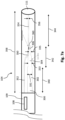
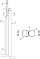
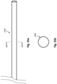
- the intravascular device 100 includes a flexible elongate member 102 having a distal portion 104 adjacent a distal tip 111 and a proximal portion 106 adjacent a proximal end 107.
- the flexible elongate member 102 can include a core member 120 and a core member 122.
- the core member 120 is disposed at the proximal portion 106 of the flexible elongate member 102, and the core member 122 is disposed along a central portion 105 and the distal portion 104 of the flexible elongate member 102.
- the core members 120 and 122 can be coupled (e.g., soldered) to one another.
- a component 108 is positioned within the distal portion 104 of the flexible elongate member 102 proximal of the distal tip 111.
- the component 108 is representative of one or more electronic, optical, or electro-optical components.
- the component 108 is a pressure sensor, a flow sensor, a temperature sensor, an imaging element, an optical fiber, an ultrasound transducer, a reflector, a mirror, a prism, an ablation element, an RF electrode, a conductor, and/or combinations thereof.
- the specific type of component or combination of components can be selected based on an intended use of the intravascular device.
- the component 108 is positioned less than 10 cm, less than 5, or less than 3 cm from the distal tip 111.
- the component 108 is positioned within a housing 109.
- the housing 109 is a separate component secured to the core member 122 in some instances.
- the housing 109 is integrally formed as part of the core member 122.
- a pocket or recess sized and shaped to receive the component 108 can be machine formed at a distal portion of the core member 122.
- the intravascular device 100 also includes a connector 110.
- the connector 110 can be a hypotube positioned such that it surrounds the core members 120 and 122 where the two are coupled (e.g., soldered) to one another.
- the connector 110 is generally positioned between the core members 120 and 122.
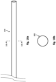
- the core members 120 and 122 can be any length. As illustrated in Fig. 1 , the distance 112 is between 0% and 50% of the total length of the flexible elongate member 102. While the total length of the flexible elongate member can be any length, in some embodiments the total length is between about 1300 mm and about 4000 mm, with some specific embodiments have a length of 1400 mm, 1900 mm, and 3000 mm.
- electrical conductors and/or optical pathways associated with the component 108 are embedded within the core of the flexible elongate member 102, as described in U.S. Patent Application US 20150217090 A1 .
- any number of electrical conductors, optical pathways, and/or combinations thereof can extend along the length of the flexible elongate member 102, embedded in the core or not.
- between one and ten electrical conductors and/or optical pathways extend along the length of the flexible elongate member 102.
- the number of communication pathways and the number of electrical conductors and optical pathways extending along the length of the flexible elongate member 102 is determined by the desired functionality of the component 108 and the corresponding elements that define component 108 to provide such functionality.
- the diameter of the core member 122 can be constant along a central portion 105 of the flexible elongate member 102.
- the central portion 105 of the flexible elongate member 102 can be surrounded by a polyimide sleeve including an embedded coil.
- the diameter of the core member 122 can decrease adjacent to the distal section 104 of the flexible elongate member 102.
- the core member 122 includes a tapered section 124 with a decreasing diameter.
- the housing 109 can be coupled to the core member 122 at the tapered section 124.
- the core member 122 can include a reduced diameter section 126 with diameter that is less than the constant diameter of the core member 122 along the central portion 105 of the flexible elongate member 102.
- the tapered section 124 and/or the reduced diameter section 126 can be shaped by grinding, ablating, cutting, pressing, etc. As described herein, the reduced diameter section 126 of the core member 122 can include two or more flattened sections. The reduced diameter section 126 can extend at least partially along the distal portion 104 of the flexible elongate member 102.
- the central portion 105 and the distal portion 104 of the flexible elongate member 102 can be partially or fully filled with adhesives 113 and 114 that surround the core member 122.
- the adhesives 113 and 114 can have the same or differing physical characteristics, including flexibility and hardness.
- adhesive 113 can be medium/low durometer, flexible adhesive, while adhesive 114 can be a low durometer, flexible adhesive.
- the housing 109 can be surrounded by and/or filled with an adhesive.
- the distal portion 104 of the flexible elongate member 102 can include a shaping ribbon 130 coupled to the reduced diameter section 126 of the core member 122.
- the shaping ribbon 130 can be coupled to various components of the intravascular device 100, including the housing 109 and/or adhesive within and/or surround the housing 109, the core member 122, and/or the distal tip 111.
- the distal portion 104 of the flexible elongate member 102, including some or all of the reduced diameter section 126 of the core member 122, the shaping ribbon 130, and the distal tip 11, can have length 125.
- the length 125 can be in the range of about 1 cm to about 25 cm, about 1 cm to about 20 cm, about 1 cm to about 10 cm, etc., including values such 3 cm, 15 cm, 25 cm, etc.
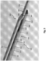
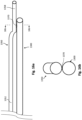
- Figs. 3-7c illustrate aspects of the distal portion 104 of the intravascular device 100 according to an exemplary embodiment.
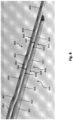
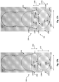
- Fig. 3 illustrates various components of the distal portion 104, including a core wire 300 and a shaping ribbon 350 in an at least partially assembled configuration.
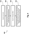
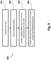
- Fig. 4 is a flow diagram of a method 400 of forming an intravascular device, such as a sensing guide wire, having the distal portion 104 illustrated in Fig. 3 .
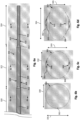
- Figs. 5a-7c illustrate the distal portion 104 at various stages of the method 400.
- the core wire 300 can include a reduced diameter section 302 and two flattened sections 304, 306.
- the core wire 300 can be similar to the core member 122 ( Fig. 2 ), and the reduced diameter section 302 can be similar to the reduced diameter section 126 ( Fig. 2 ).
- the housing 109 ( Fig. 2 ) can be located proximal of the constant diameter section 302.
- the two flattened sections 304, 306 are adjacent to one another and distal of the constant diameter section 302. In the embodiment of Fig. 3 , the flattened section 306 can be described as the distal most flattened section.
- the core wire 300 can be shaped such that the flattened section 304 includes planar regions 308 on top and bottom surfaces thereof.
- the flattened section 306 includes planar regions 310 on top and bottom surfaces thereof.
- the core wire 300 can include transition regions 312 disposed between the flattened sections 304, 306 and between the flattened section 304 and the reduced diameter section 302.
- the transition regions 312 can have a tapered profile as the cross-sectional profile of the core wire 300 changes between the flattened sections 304, 306 and between the flattened section 304 and the reduced diameter section 302.
- the shaping ribbon 350 can be coupled to the core wire 300 along at least a portion of one or more of the flattened sections 304, 306.
- a solder joint 360 can connect the core wire 300 and the shaping ribbon 350 at a portion of the flattened portion 306 of the core wire 300.
- the solder joint 360 can extend along all or some portion of the entire length of one of the flattened sections 304, 306.
- the solder joint 360 can extend along all or some portion of both flattened sections 304, 306.
- the shaping ribbon 350 can include a proximal portion 352 and a distal portion 354. At least a portion of the shaping ribbon 350 coupled to the core wire 300 can include one or more flattened sections.
- the entire length of the shaping ribbon 350 is flattened. That is, the shaping ribbon 350 can have a uniform cross-section from its proximal end to its distal end.
- the shaping ribbon 350 includes planar regions 384 on top and bottom surfaces thereof.
- the solder joint 360 can be disposed between the bottom planar region 384 of the shaping ribbon 350 and the top planar region 310 of the flattened section 306.
- the proximal portion 352 can extend proximally from the solder joint 360 and be coupled to the housing 109 ( Fig. 2 ) and/or adhesive within and/or surround the housing 109.
- the distal portion 354 can extend distally from the solder joint 360 and be coupled to the distal tip 111 ( Figs. 1 and 2 ).
- Fig. 4 is a flow diagram of a method 400 of forming the intravascular device 100, including the various components of the distal portion 104 illustrated in Fig. 3 .
- the method 400 can be better understood with reference to Figs. 5a-7c .
- the core wire 300 and the shaping ribbon 350 are solid components.
- Figs. 5b , 6b-6d , and 7c illustrate the cross-sectional contours of the core wire 300 and/or the shaping ribbon 350, and do not illustrate that the core wire 300 and/or the shaping ribbon 350 include a lumen extending therethrough.
- the method 400 can include, at step 410 acquiring a core member or a core wire. As illustrated in Figs.
- the distal portion of the core wire 300 can have a cylindrical profile with a circular cross-sectional profile.
- the core wire 300 can be described as a first flexible elongate member.
- the proximal portion of the core wire 300 illustrated in Figs. 5a-5b can have a generally constant diameter. As described with respect to Figs. 1-2 , more proximal portions of the core wire 300 can include larger diameters, with constant and/or tapered profiles.
- the core wire 300 can be formed of a flexible and/or elastic material, including metals or metal alloys such as nickel titanium or nitinol, nickel titanium cobalt, stainless steel, and/or various stainless steel alloys.
- the method 400 can include, at step 412, shaping the distal portion of the core wire to include at least two flattened sections.
- the core wire 300 includes flattened section 304, 306.
- shaping the distal portion of the core wire 300 can include cold forming the at least two flattened sections 304, 306, such as by pressing the distal portion with suitable dies.
- shaping the distal portion of the core wire 300 can include grinding, ablating, and/or cutting.
- the lengths 322, 324 of the respective flattened sections 304, 306 can be between about 0.1 cm and about 1.1 cm, about 0.1 cm and 1.0 cm, about 0.1 cm and 0.5 cm, etc., including values such as 0.2 cm, 0.5 cm, 1 cm, etc. In some embodiments, the lengths 322, 324 are the same. For example, in one embodiment, the lengths 322, 324 are 0.5 cm each. In some embodiments, the lengths 322, 324 are different. For example, the length of more proximal flattened sections (e.g., the flattened section 304) can be greater than the length of more distal flattened sections (e.g., the flattened section 306).
- length 324 is 0.2 cm and length 322 is 0.5 cm.
- a dimension of the distal most flattened section is different from the dimension of the other flattened sections.
- a combined length 342 ( Fig. 7a ) of the flattened sections 304, 306 is the same regardless of the whether the individual lengths 322, 324 are the same or different.
- the combined length 342 ( Fig. 7a ) can be 1 cm.
- the core wire 300 can include one flattened section, or three or more flattened sections in different embodiments.
- the core wire 300 can be shaped such that the flattened section 304 includes planar regions 308 and the flattened section 306 includes planar regions 310.
- the planar regions 308, 310 can be disposed on opposite sides of the respective flattened sections 304, 306.
- the planar regions 308, 310 are disposed on top and bottom surfaces of the respective flattened sections 304, 306.
- planar regions 308, 310 can be variously positioned around the perimeter of the respective flattened sections 304, 306.
- the respective flattened sections 304, 306 include only one planar region 308, 310 (e.g., top planar regions that are adjacent to the shaping ribbon 350).
- the core wire 300 can also include a reduced diameter section 302.
- a length 340 of the reduced diameter section 302, between the housing 109 and the proximal most transition region 312 can be, for example, 1 cm.
- the cross-sectional profiles of the flattened sections 304, 306 can be different from each other and different from the cross-sectional profile of the reduced diameter section 302.
- the cross-sectional profile of the reduced diameter section 302 is substantially circular.
- a width 330, a height 331, and/or a diameter of the reduced diameter section 302 can be between about 0.0254 mm (0.001") and 0.0762 mm (0.003"), about 0.0254 mm (0.001") and 0.0508 mm (0.002”), etc., including values such as 0.0381 mm (0.0015"), 0.0508 mm (0.002"), 0.5715 mm (0.00225”), etc.
- the cross-sectional profiles of the respective flattened portions 304, 306 can be substantially non-circular.
- the cross-sectional profiles of the flattened portions 304, 306 can be substantially oval-shaped.
- the cross-sectional profile of the flattened portion 304 can be taller than the cross-sectional profile of the flattened portion 306.
- the height 333 of the flattened portion 304 can be between about 0.0254 mm (0.001") and 0.0762 mm (0.003"), about 0.0254 mm (0.001") and 0.0508 mm (0.002"), etc., including values such as 0.0381 mm (0.0015"), 0.04445 mm (0.00175"), 0.0508 mm (0.002"), etc.
- the height 335 of the flattened portion 306 can be between about 0.0254 mm (0.001") and 0.0762 mm (0.003"), about 0.0254 mm (0.001") and 0.0508 mm (0.002"), etc., including values such as 0.03175 mm (0.00125”), 0.0381 mm (0.0015"), 0.04445 mm (0.00175"), etc.
- the cross-sectional profile of the flattened portion 304 can be wider than the cross-sectional profile of the flattened portion 306.
- the width 332 of the flattened portion 304 can be between about 0.0254 mm (0.001") and 0.127 mm (0.005"), about 0.0254 mm (0.001") and 0.0762 mm (0.003"), etc., including values such as 0.0381 mm (0.0015"), 0.0508 mm (0.002"), 0.0635 mm (0.0025”), etc.
- the width 334 of the flattened portion 306 can be between about 0.0254 mm (0.001") and 0.127 mm (0.005"), about 0.0254 mm (0.001") and 0.0762 mm (0.003"), etc., including values such as 0.0508 mm (0.002"), 0.5715 mm (0.00225”), 0.0635 mm (0.0025”), etc.
- a dimension of the distal most flattened section is different from the dimension of the other flattened sections. While the cross-sectional profiles of the reduced diameter section 302 and the flattened sections 304, 306 are shaped differently, the cross-sectional areas can be substantially similar.
- the method 400 can include, at step 430, acquiring a shaping ribbon.
- the shaping ribbon 350 is illustrated, along with the core wire 300, in Figs. 7a-7c .
- the shaping ribbon 350 can be described herein as a second flexible elongate member.
- the shaping ribbon 350 can be formed a shapeable material including, for example, a metal or metal alloy such as stainless steel and/or other suitable materials. Including the shaping ribbon 350 at the distal portion of the intravascular device 100 allows for the tip of the intravascular device to be shaped, allowing the device to be steered efficiently through tortuous anatomy, such as a patient's blood vessels.
- the shaping ribbon 350 can have a cylindrical profile with a circular cross-sectional profile when acquired.
- the method 400 can include shaping the shaping ribbon to include one or more flattened sections. For example, an entire length of the shaping ribbon can be flattened. Shaping the shaping ribbon 350 can occur before the shaping ribbon 350 and the core wire 300 are coupled (step 440).
- shaping the shaping ribbon 350 can include pressing, grinding, ablating, and/or cutting.
- shaping the shaping ribbon 350 can be similar to shaping the core wire 300 (step 420).
- the shaping ribbon 350 can include the one or more flattened sections when acquired.
- the shaping ribbon 350 can include planar regions 384.
- the planar regions 384 can be disposed on opposite sides of the shaping ribbon 350.
- the planar regions 384 are disposed on top and bottom surfaces of the shaping ribbon 350.
- planar regions 384 can be variously positioned around the perimeter of the shaping ribbon 350.
- the shaping ribbon 350 includes only one planar region 384 (e.g., a bottom planar region that is adjacent to the core wire 300).
- the shaping ribbon 350 can have a substantially oval cross-sectional profile.
- a height 363 of the shaping ribbon 350 can be between about 0.0254 mm (0.001") and 0.0762 mm (0.003"), about 0.0254 mm (0.001") and 0.0508 mm (0.002"), etc., including values such as 0.03175 mm (0.00125”), 0.0381 mm (0.0015"), 0.04445 mm (0.00175"), etc.
- a width 362 of the shaping ribbon 350 can be between about 0.0254 mm (0.001") and 0.127 mm (0.005"), about 0.0254 mm (0.001") and 0.0762 mm (0.003"), etc., including values such as 0.0508 mm (0.002"), 0.5715 mm (0.00225”), 0.0635 mm (0.0025”), etc.
- the method 400 can include, at step 440, coupling the shaping ribbon and the core wire along a portion of one of the at least two flattened portions of the core wire.
- a central portion of the shaping ribbon 350 and the core wire 300 can be coupled at the flattened section 306 (e.g., the distal most flattened section).
- the solder joint 360 can extend along all or some portion of the entire length of one of the flattened sections 304, 306.
- the solder joint 360 can extend along all or some portion of both flattened sections 304, 306.
- the solder joint 360 can be disposed between the shaping ribbon 350 and the core wire 300.
- coupling the shaping ribbon 350 and the core wire 300 can include introducing solder between the shaping ribbon 350 and the core wire 300, or tack soldering the shaping ribbon 350 and the core wire 300.
- the solder joint 360 can have a length between about 0.1 cm to about 1 cm, about 0.1 cm to .5 cm, etc., including values such as 0.1 cm, 0.25 cm, 0.5 cm, etc.
- the bottom planar region 384 of the shaping ribbon 350 can be soldered to the top planar region 310 of the core wire 300
- the distal portion 354 of the shaping ribbon 350 can extend distally from the core wire 300 and/or the solder joint 360.
- the distal portion 354 can terminate at and be coupled to the distal tip 111.
- a proximal portion 352 can extend proximally from the solder joint 360.
- the proximal portion 352 can terminate at and be coupled to the housing 109 ( Fig. 2 ) and/or adhesive within and/or surround the housing 109.
- a length 344 of the distal portion 354 of the shaping ribbon 350 (e.g., between the distal end of the core wire 300 and the distal tip 111), the combined length 342 of the flattened portions 304, 306 of the core wire 300, and/or a length 340 of the reduced diameter section 302 of the core wire 300 (e.g., between the housing 109 and the proximal most flattened section) can each be between about 0.1 cm and about 5 cm, about 0.1 cm and 2 cm, about 0.1 cm and 1 cm, etc., including values such as 0.5 cm, 1 cm, 1.5 cm, etc.
- the lengths 340, 342, 344 can be the same or different in various embodiments. In an exemplary embodiment, the lengths 340, 342, 344 are each 1 cm, such that the length 358 of the distal portion 104 of the intravascular device 100 is 3 cm.
- the length 358 can be similar to the length 125 ( Fig. 2 ).
- the method 400 can include additional steps to incorporate the element 108 within the intravascular device 100.
- the method 400 can include coupling the housing 109 to the core wire 300, when the housing 109 is a separate component.
- the method 400 can include forming a recess within the core member 300.
- the recess can be sized and shaped to accommodate the element 108.
- the method 400 can also include coupling the element 108 to the core member 300 (e.g., within the housing 109 or within the recess formed within the core member 300).
- the element 108 can be positioned at a distal portion of the core member 300.
- the method 400 can include various other steps to complete assembly of the intravascular device 100, including electrically coupling the element 108 to other component(s) of the intravascular device 100, introducing adhesive(s) into a lumen of the flexible elongate member 102, coupling the core member 120 and the core member 122, introducing a sleeve (e.g., with an integrated coil) around the flexible elongate member 102, introducing a tip coil around the distal portion 104, among others.
- a sleeve e.g., with an integrated coil
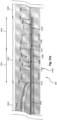
- Figs. 8-12c illustrate aspects of the distal portion 104 of the intravascular device 100 according to an exemplary embodiment.
- Fig. 8 illustrates various components of the distal portion 104, including a core member 800 and a shaping ribbon 850 in an at least partially assembled configuration.
- Fig. 9 is a flow diagram of a method 900 of forming an intravascular device, such as a sensing guide wire, having the distal portion 104 illustrated in Fig. 8 .
- Figs. 10a-12c illustrate the distal portion 104 at various stages of the method 900.
- the core member 800 can include a reduced diameter section 802 and two flattened sections 804, 806.
- the core member 800 can be similar to the core member 122 ( Fig. 2 ) and the core member 300 ( Fig. 3 ).
- the reduced diameter section 802 can be similar to the reduced diameter section 126 ( Fig. 2 ) and the reduced diameter section 302 ( Fig. 3 ).
- the housing 109 ( Fig. 2 ) can be located proximal of the constant diameter section 802.
- the two flattened sections 804, 806 are adjacent to one another and distal of the constant diameter section 802. In the embodiment of Fig. 8 , the flattened section 806 can be described as the distal most flattened section of the core member 800.
- the core member 800 can be shaped such that the flattened section 804 includes planar regions 808 on top and bottom surfaces thereof. Similarly, the flattened section 806 includes planar regions 810 on top and bottom surfaces thereof.
- the core member 800 can include transition regions 812 disposed between the flattened sections 804, 806 and between the flattened section 804 and the reduced diameter section 802.
- the transition regions 812 can have a tapered profile as the cross-sectional profile of the core wire 800 changes between the flattened sections 804, 806 and between the flattened section 804 and the reduced diameter section 802.
- the shaping ribbon 850 can be coupled to the core member 800 along a portion of one or more of the flattened sections 804, 806.
- a solder joint can extend along all or some portion of the entire length of one of the flattened sections 806, 808.
- the solder joint can extend along all or some portion of both flattened sections 806, 808.
- the shaping ribbon 850 and the core member 800 can be coupled at the flattened section 806.
- the flattened section 806 can include a solder joint to connect the shaping ribbon 850 and the core member 800.
- the shaping ribbon 850 and the core member 800 can be coupled at two or more of the flattened sections 804, 806. Solder can be disposed along both flattened sections 804, 806 to connect the shaping ribbon 850 and the core member 800.
- the shaping ribbon 850 can include two or more flattened sections 854, 856.
- the entire length of the shaping ribbon 850 is flattened. That is, the shaping ribbon 850 can have a uniform cross-section from its proximal end to its distal end.
- the two flattened sections 854, 856 are adjacent to one another and positioned between the proximal portion 852 and the distal portion 858.
- the flattened sections 854, 856 of the shaping ribbon 850 can be longitudinally aligned with the flattened portions 804, 806 of the core member 800.
- the shaping ribbon 850 can be shaped such that the flattened section 854 includes planar regions 882 on top and bottom surfaces thereof.
- the flattened section 856 includes planar regions 884 on top and bottom surfaces thereof.
- a solder joint can be disposed between the bottom planar region 884 of the shaping ribbon 850 and the top planar region 810 of the flattened section 806 and/or between the bottom planar region 882 of the shaping ribbon 850 and the top planar region 808 of the flattened section 804.
- the shaping ribbon 850 can include transition regions 862 disposed between the flattened sections 854, 856 and between the flattened section 854 and the proximal portion 852. The transition regions 862 of the shaping ribbon 850 can be aligned with the transition regions 812 of the core member 800.
- the proximal portion 852 of the shaping ribbon 850 can extend proximally from the flattened sections 854, 856, and be coupled to the housing 109 ( Fig. 2 ) and/or adhesive within and/or surround the housing 109.
- the distal portion 854 can extend distally from the flattened sections 854, 856, and be coupled to the distal tip 111 ( Figs. 1 and 2 ).
- Fig. 9 is a flow diagram of a method 900 of forming the intravascular device 100, including the various components of the distal portion 104 illustrated in Fig. 8 .
- the method 900 can be better understood with reference to Figs. 10a-12c .
- the core wire 800 and the shaping ribbon 850 are solid components.
- Figs. 10b , 11b , 12b, and 12c illustrate the cross-sectional contours of the core wire 800 and/or the shaping ribbon 850, and do not illustrate that the core wire 800 and/or the shaping ribbon 850 include a lumen extending through.
- the method 900 can include, at step 910 acquiring a core member or a core wire.
- the distal portion of the core wire 800 is illustrated in Figs. 10a-10b .
- the core wire 800 can be similar to the core wire 122 and/or core wire 300 ( Fig. 3 ), and can be similarly described as a first flexible elongate member.
- the method 900 can include, acquiring a shaping ribbon.
- the shaping ribbon 850 is illustrated, along with the core wire 800, in Figs. 11a-11b .
- the shaping ribbon 850 can be similar to the shaping ribbon 350 ( Fig. 3 ) and can be similarly described as a second flexible elongate member.
- the cross-sectional profile of the shaping ribbon 850 is shown to include one or more flattened sections in Figs. 11a-11b .
- the shaping ribbon 850 can include the one or more flattened sections when acquired.
- the shaping ribbon 850 can have a cylindrical profile with a circular cross-sectional profile when acquired.
- the method 900 can include shaping the shaping ribbon to include one or more flattened sections. For example, an entire length of the shaping ribbon can be flattened.
- shaping the shaping ribbon 850 can occur before the shaping ribbon 850 and the core wire 800 are coupled (step 930).
- shaping the shaping ribbon 850 can include pressing, grinding, ablating, and/or cutting.
- shaping the shaping ribbon 850 can be similar to shaping the core wire 800 (step 940), as described below.
- the method 900 can include, at step 930, coupling the shaping ribbon and the core wire at a distal portion of the core wire.
- a central portion of the shaping ribbon 850 and the core wire 800 can be coupled at a distal portion of the core wire.
- a solder joint 870 can be disposed between the shaping ribbon 850 and the distal portion of the core wire 800.
- coupling the shaping ribbon 850 and the core wire 800 can include introducing solder between the shaping ribbon 850 and the core wire 800.
- the solder joint 870 can have a length between about 0.1 cm to about 2 cm, about 0.1 cm to about 1 cm, about 0.1 cm to .
- solder can be introduced multiple times during the method 900 to couple the shaping ribbon 850 and the core wire 800.
- solder can be introduced between the shaping ribbon 850 and the core wire 800 during step 930 and again when the distal portion of the core wire 800 is shaped to include at least two flattened portions (step 940).
- the method 900 can include, at step 940, shaping the distal portion of the core wire to include at least two flattened sections.
- the core wire 800 includes flattened sections 804, 806.
- Shaping the distal portion of the core wire 800 can include cold forming the at least two flattened sections 804, 806, such as by pressing core wire 800 with suitable dies.
- the distal portion of the core wire 800 can be shaped such that the respective flattened sections of the core wire 800 and the shaping ribbon 850 are longitudinally aligned.
- Pressure can be applied to the distal portion of the core wire 800 to form the flattened sections 804, 806 while the shaping ribbon 850 is coupled to the core wire 800.
- the pressure that shapes the core wire 800 can be also experienced by the shaping ribbon 850. That is, the applied pressure can shape both the core wire 800 and the shaping ribbon 850.
- the method 900 can include introducing solder between the shaping ribbon 850 and the core wire 800 as pressure is being applied to the shaping ribbon and/or the core wire.
- solder can be introduced at a distal most flattened section (e.g., flattened section 806) of the core wire 800.
- solder can be introduced along two or more of the flattened sections (e.g., flattened sections 804, 806) of the core wire 800. Introducing additional solder when the shaping ribbon 850 and/or the core wire 800 is shaped can ensure that the coupling between the shaping ribbon and the core wire remains after pressure is applied.
- the bottom planar region 884 of the flattened section 856 of the shaping ribbon 850 can be soldered to the top planar region 810 of the core wire 800 and/or the bottom planar region 882 of the shaping ribbon 850 can be soldered to the top planar region 808 of the core wire 800.
- the flattened sections 804, 806 of the core wire 800 can be similar to the respective flattened sections 304, 306 ( Fig. 6a-6d ) of the core wire 300.
- the lengths 822, 824 of the respective flattened sections 804, 806 can be between about 0.1 cm and about 1 cm, about 0.1 cm and 0.8 cm, about 0.1 cm and 0.6 cm, etc., including values such as 0.5 cm, 0.6 cm, 0.8 cm, etc.
- a combined length 842 of the flattened sections 804, 806 is the same regardless of the whether the individual lengths 822, 824 are the same or different.
- the combined length 842 can be 1 cm.
- a reduced diameter section 802 can be similar to the reduced diameter section 302 ( Figs. 6a-6b ).
- a length 840 of the reduced diameter section 802, between the housing 109 and the proximal most transition region 812 can be, for example, 1 cm.
- the core wire 800 can include one flattened section, or three or more flattened sections in different embodiments.
- the core wire 800 can be shaped such that the flattened section 804 includes planar regions 808 and the flattened section 806 includes planar regions 810.
- the planar regions 808, 810 can be similar to the planar regions 308, 310 ( Figs. 6a-6d ).
- the cross-sectional profiles of the flattened sections 804, 806 can be different from each other and different from the cross-sectional profile of the reduced diameter section 802.
- the cross-sectional profiles of the flattened sections 804, 806 and the reduced diameter section 802 can be similar to the respective cross-sectional profiles of the flattened section 304, 306 and the reduced diameter section 302.
- the cross-sectional profile of the flattened portion 804 can be taller than the cross-sectional profile of the flattened portion 806.
- the height 833 of the flattened portion 804 can be between about 0.0254 mm (0.001") and 0.0762 mm (0.003"), about 0.0254 mm (0.001") and 0.0508 mm (0.002"), etc., including values such as 0.0381 mm (0.0015"), 0.04445 mm (0.00175"), 0.0508 mm (0.002”), etc.
- the height 835 of the flattened portion 806 can be between about 0.0254 mm (0.001") and 0.0762 mm (0.003"), about 0.0254 mm (0.001") and 0.0508 mm (0.002"), etc., including values such as 0.03175 mm (0.00125”), 0.0381 mm (0.0015"), 0.04445 mm (0.00175"), etc.
- the cross-sectional profile of the flattened portion 804 can be wider than the cross-sectional profile of the flattened portion 806.
- the width 832 of the flattened portion 804 can be between about 0.0254 mm (0.001") and 0.127 mm (0.005"), about 0.0254 mm (0.001") and 0.0762 mm (0.003"), etc., including values such as 0.0381 mm (0.0015"), 0.0508 mm (0.002"), 0.0635 mm (0.0025”), etc.
- the width 834 of the flattened portion 806 can be between about 0.0254 mm (0.001") and 0.127 mm (0.005"), about 0.0254 mm (0.001") and 0.0762 mm (0.003"), etc., including values such as 0.0508 mm (0.002"), 0.5715 mm (0.00225”), 0.0635 mm (0.0025”), etc.
- the flattened sections 854, 856 of the shaping ribbon 850 can include planar regions 882, 884, respectively.
- the planar regions 882, 884 can be similar to the planar regions 384 ( Fig. 7b-7c ).
- the cross-sectional profiles of the flattened sections 854, 856 are substantially oval shaped.
- the cross-sectional profiles can also be described as rectangular with rounded sides.
- the dimensions of the cross-sectional profiles of the flattened sections 882, 884 can be the same or similar.
- a height 863 of the flattened sections 882, 884 of the shaping ribbon 850 can be between about 0.0254 mm (0.001") and 0.0762 mm (0.003"), about 0.0254 mm (0.001") and 0.0508 mm (0.002"), etc., including values such as 0.03175 mm (0.00125”), 0.0381 mm (0.0015"), 0.04445 mm (0.00175"), etc.
- a width 862 of the flattened sections 882, 884 of the shaping ribbon 850 can be between about 0.0254 mm (0.001") and 0.127 mm (0.005"), about 0.0254 mm (0.001") and 0.0762 mm (0.003"), etc., including values such as 0.0508 mm (0.002"), 0.5715 mm (0.00225”), 0.0635 mm (0.0025”), etc. While only two flattened sections 854, 856 of the shaping ribbon 850 are illustrated, it is understood that the shaping ribbon can include one flattened section, or three or more flattened sections in different embodiments.
- the distal portion 858 of the shaping ribbon 850 can extend distally from the core wire 800 and/or the solder joint 870.
- the distal portion 858 can terminate at and be coupled to the distal tip 111.
- a proximal portion 852 can extend proximally from the solder joint 870 and/or the proximal most flattened section (e.g., flattened section 854) of the shaping ribbon 850.
- the proximal portion 852 can terminate at and be coupled to the housing 109 ( Fig. 2 ) and/or adhesive within and/or surround the housing 109.
- a length 844 of the distal portion 854 of the shaping ribbon 850 (e.g., between the distal end of the core wire 800 and the distal tip 111), the combined length 842 of the flattened portions 804, 806 of the core wire 800, and/or a length 840 of the reduced diameter section 802 of the core wire 800 (e.g., between the housing 109 and the proximal most flattened section) can each be between about 0.1 cm and about 5 cm, about 0.1 cm and 2 cm, about 0.1 cm and 1 cm, etc., including values such as 0.5 cm, 1 cm, 1.5 cm, etc.
- the lengths 840, 842, 844 can be similar to the lengths 340, 342, 344 ( Figs. 7a-7b ).
- the method 900 can include additional steps to incorporate the element 108 within the intravascular device 100.
- the method 900 can include coupling the housing 109 to the core wire 800, when the housing 109 is a separate component.
- the method 900 can include forming a recess within the core member 800.
- the recess can be sized and shaped to accommodate the element 108.
- the method 400 can also include coupling the element 108 to the core member 800 (e.g., within the housing 109 or within the recess formed within the core member 800).
- the element 108 can be positioned at a distal portion of the core member 800.
- the method 900 can include various other steps to complete assembly of the intravascular device 100, including electrically coupling the element 108 to other component(s) of the intravascular device 100, introducing adhesive(s) into a lumen of the flexible elongate member 102, coupling the core member 120 and the core member 122, introducing a sleeve (e.g., with an integrated coil) around the flexible elongate member 102, introducing a tip coil around the distal portion 104, among others.
- a sleeve e.g., with an integrated coil
- Figs. 13-17c illustrate aspects of the distal portion 104 of the intravascular device 100 according to an exemplary embodiment.
- Fig. 13 illustrates various components of the distal portion 104, including a core wire 1300 and a core wire 1350 in an at least partially assembled configuration.
- Fig. 14 is a flow diagram of a method 1400 of forming an intravascular device, such as a sensing guide wire, having the distal portion 104 illustrated in Fig. 13 .
- Figs. 15a-17c illustrate the distal portion 104 at various stages of the method 1400.
- the embodiment of the distal portion 104 of the intravascular device 100 illustrated and described with respect Figs. 13-17c is substantially similar to the embodiment illustrated and described with respect to Figs. 8-12c .
- the embodiment of Figs. 13-17c includes two core wires: the core wire 1300 having at least two flattened portions, and a core wire 1350 coupled to and extending distally from the core wire 1300.
- the core wire 1350 can have a smaller diameter compared to the core wire 1300.
- the embodiment of Figs. 8-12c included the core wire 800 having at least two flattened sections, and the shaping ribbon 850 coupled to and extending distally from the core wire 800.
- the embodiments of Figs. 8-12c included the core wire 800 having at least two flattened sections, and the shaping ribbon 850 coupled to and extending distally from the core wire 800.
- the core wire 1350 assumes the role of the shaping ribbon 850.
- Using two core wires can allow for more efficient manufacturing of the intravascular device 100 because no particular orientation for the core wire 1350 need be maintained when coupling the core wires 1300, 1350 and/or when forming the respective at least two flattened sections of the core wires 1300, 1350.
- the core wire 1300 can include a reduced diameter section 1302 and two flattened sections 1304, 1306.
- the core wire 1300 can be similar to the core wire 122 ( Fig. 2 ), the core wire 300 ( Fig. 3 ), and/or the core wire 800 ( Fig. 8 ).
- the reduced diameter section 1302 can be similar to the reduced diameter section 126 ( Fig. 2 ), the reduced diameter section 302 ( Fig. 3 ), and/or the reduced diameter section 802 ( Fig. 8 ).
- the housing 109 ( Fig. 2 ) can be located proximal of the constant diameter section 1302.
- the two flattened sections 1304, 1306 are adjacent to one another and distal of the constant diameter section 1302. In the embodiment of Fig.
- the flattened section 1306 can be described as the distal most flattened section of the core wire 1300.
- the core wire 1300 can be shaped such that the flattened section 1304 includes planar regions 1308 on top and bottom surfaces thereof. Similarly, the flattened section 1306 includes planar regions 1310 on top and bottom surfaces thereof.
- the core wire 1300 can include transition regions 1312 disposed between the flattened sections 1304, 1306 and between the flattened section 1304 and the reduced diameter section 1302.
- the transition regions 1312 can have a tapered profile as the cross-sectional profile of the core wire 1300 changes between the flattened sections 1304, 1306 and between the flattened section 1304 and the reduced diameter section 1302.
- the core wire 1350 can be coupled to the core wire 1300 along a portion of one or more of the flattened sections 1304, 1306.
- a solder joint can extend along all or some portion of the entire length of one of the flattened sections 1306, 1308.
- the solder joint can extend along all or some portion of both flattened sections 1306, 1308.
- the core wire 1350 and the core wire 1300 can be coupled at the flattened section 1306.
- the flattened section 1306 can include a solder joint to connect the core wire 1350 and the core wire 1300.
- the core wire 1350 and the core wire 1300 can be coupled at two or more of the flattened sections 1304, 1306.
- Solder can be disposed both flattened sections 1304, 1306 to connect the core wire 1350 and the core wire 1300.
- the core wire 1350 can include two or more flattened sections 1354, 1356.
- the entire length of the shaping ribbon 1350 is flattened. That is, the shaping ribbon 1350 can have a uniform cross-section from its proximal end to its distal end.
- the two flattened sections 1354, 1356 are adjacent to one another and positioned between the proximal portion 1352 and the distal portion 1358.
- the flattened sections 1354, 1356 of the core wire 1350 can be longitudinally aligned with the flattened portions 1304, 1306 of the core member 1300.
- the core wire 1350 can be shaped such that the flattened section 1354 includes planar regions 1382 on top and bottom surfaces thereof.
- the flattened section 1356 includes planar regions 1384 on top and bottom surfaces thereof.
- a solder joint can be disposed between the bottom planar region 1384 of the core wire 1350 and the top planar region 1310 of the flattened section 1306 and/or between the bottom planar region 1382 of the core wire 1350 and the top planar region 1308 of the flattened section 1304.
- the core wire 1350 can include transition regions 1362 disposed between the flattened sections 1354, 1356 and between the flattened section 1354 and the proximal portion 1352. The transition regions 1362 of the core wire 1350 can be aligned with the transition regions 1312 of the core wire 1300.
- the proximal portion 1352 of the core wire 1350 can extend proximally from the flattened sections 1354, 1356, and be coupled to the housing 109 ( Fig. 2 ) and/or adhesive within and/or surround the housing 109.
- the distal portion 1354 can extend distally from the flattened sections 1354, 1356, and be coupled to the distal tip 111 ( Figs. 1 and 2 ).
- Fig. 14 is a flow diagram of a method 1400 of forming the intravascular device 100, including the various components of the distal portion 104 illustrated in Fig. 13 .
- the method 1400 can be better understood with reference to Figs. 15a-17c . It is understood that the core wire 1300 and the shaping ribbon 1350 are solid components. Figs. 15b , 16b , 17b, and 17c illustrate the cross-sectional contours of the core wire 1300 and/or the shaping ribbon 1350, and do not illustrate that the core wire 1300 and/or the shaping ribbon 1350 include a lumen extending therethrough.
- the method 1400 can include, at step 1410 acquiring a first core member or a first core wire.
- the distal portion of the core wire 1300 is illustrated in Figs. 10a-10b .
- the core wire 1300 can be similar to the core wire 300 ( Fig. 3 ) and/or the core wire 800 ( Fig. 8 ), and can be similarly described as a first flexible elongate member.
- the method 1400 can include, acquiring a second core wire.
- the core wire 1350 is illustrated, along with the core wire 1300, in Figs. 16a-16b .
- the core 1350 can be described herein as a second flexible elongate member.
- the diameter of the core wire 1300 and/or the core wire 1350 is in the range of about 0.0254 mm (0.001") to about 0.1016 mm (0.004"), about 0.0254 mm (0.001") to about 0.0762 mm (0.003"), about 0.0254 mm (0.001") to about 0.0508 mm (0.002"), etc., including values such as 0.0381 mm (0.0015"), 0.0508 mm (0.002"), 0.0635 mm (0.0025"), etc.
- the core wire 1350 can have a smaller diameter compared to the core wire 1300.
- the core wire 1300 and/or the core wire 1350 can be formed a shapeable material including, for example, a metal or metal alloy such as stainless steel and/or other suitable materials. Including the core wire 1350 at the distal portion of the intravascular device 100 allows for the intravascular device to be steered efficiently through the tortuous anatomy, such as a patient's blood vessels.
- the core wire 1350 can have a cylindrical profile with a circular cross-sectional profile when acquired.
- the method 1400 can include shaping the second core wire to include two or more flattened sections.
- shaping the core wire 1350 can occur after the core wire 1350 and the core wire 1300 are coupled (step 1430) and simultaneously as the distal portion of the core wire 1300 is shaped to include at least two flattened portions (step 1440).
- the method 1400 can include, at step 1430, coupling the first core wire and the second core wire at a distal portion of the first core wire.
- a central portion of the core wire 1350 and the core wire 1300 can be coupled at a distal portion of the core wire 1300.
- a solder joint 1370 can be disposed between the core wire 1350 and the distal portion of the core wire 1300.
- coupling the core wire 1350 and the core wire 1300 can include introducing solder between the core wire 1350 and the core wire 1300.
- the solder joint 1370 can have a length between about 0.1 cm to about 2 cm, about 0.1 cm to about 1 cm, about 0.1 cm to .5 cm, etc., including values such as 0.25 cm, 0.5 cm, 0.75 cm, etc.
- solder can be introduced multiple times during the method 1400 to couple the core wire 1350 and the core wire 1300.
- solder can be introduced between the core wire 1350 and the core wire 1300 during step 1430 and again when the core wires 1300, 1350 are shaped to include respective at least two flattened portions (step 1340).
- the method 1400 can include, at step 1440, shaping the first and second core wires to include respective at least two flattened sections.
- the core wire 1300 includes flattened sections 1304, 1306, and the core wire 1350 can include flattened sections 1354, 1356. Shaping the distal portion of the core wire 1300 can occur simultaneously shaping the core wire 1350. Shaping the distal portion of the core wires 1300, 1350 can include cold forming the respective at least two flattened sections, such as by pressing core wires 1300, 1350 with suitable dies.
- the core wire 1350 is coupled to the distal portion of the core wire 1300 (step 930), pressure can be simultaneously applied to both the core wires 1300, 1350 to the form the respective at least two flattened sections.
- the core wires 1300, 1350 can be shaped such that the respective flattened sections are longitudinally aligned. In other embodiments, shaping the core wires 1300, 1350 can include grinding, ablating, and/or cutting.
- the method 1400 can include introducing solder between the core wires 1300, 1350 as pressure is being simultaneously applied to the core wires 1300, 1350.
- solder can be introduced at a distal most flattened section (e.g., flattened section 1306) of the core wire 1300.
- solder can be introduced along two or more of the flattened sections (e.g., flattened sections 1304, 1306) of the core wire 1300. Introducing additional solder when the core wires 1300, 1350 are shaped can ensure that the coupling between the core wires remains after pressure is applied.
- the bottom planar region 1384 of the flattened section 1356 of the core wire 1350 can be soldered to the top planar region 1310 of the core wire 1300 and/or the bottom planar region 1382 of the core wire 1350 can be soldered to the top planar region 1308 of the core wire 1300.
- the flattened sections 1304, 1306 of the core wire 1300 can be similar to the respective flattened sections 304, 306 ( Fig. 6a-6d ) of the core wire 300 and/or the respective flattened sections 804, 806 ( Figs. 12a-12c ) of the core wire 800.
- the lengths 1322, 1324 of the respective flattened sections 1304, 1306 can be between about 0.1 cm and about 1 cm, about 0.1 cm and 0.8 cm, about 0.1 cm and 0.6 cm, etc., including values such as 0.5 cm, 0.6 cm, 0.8 cm, etc.
- a combined length 1342 of the flattened sections 1304, 1306 is the same regardless of the whether the individual lengths 1322, 1324 are the same or different.
- the combined length 1342 can be 1 cm.
- a reduced diameter section 1302 can be similar to the reduced diameter section 1302 ( Figs. 6a-6b ).
- a length 1340 of the reduced diameter section 1302, between the housing 109 and the proximal most transition region 1312 can be, for example, 1 cm.
- the core wire 1300 can include one flattened section, or three or more flattened sections in different embodiments.
- the core wire 1300 can be shaped such that the flattened section 1304 includes planar regions 1308 and the flattened section 1306 includes planar regions 1310.
- the planar regions 1308, 1310 can be similar to the planar regions 308, 310 ( Figs. 6a-6d ) and/or the planar regions 808, 810 ( Figs. 12a-12c ).
- the cross-sectional profiles of the flattened sections 1304, 1306 can be different from each other and different from the cross-sectional profile of the reduced diameter section 1302.
- the cross-sectional profiles of the flattened sections 1304, 1306 and the reduced diameter section 1302 can be similar to the respective cross-sectional profiles of the flattened section 304, 306 and the reduced diameter section 302, and/or the respective cross-sectional profiles of the flattened sections 804, 806, and the reduced diameter section 802.
- the cross-sectional profile of the flattened portion 1304 can be taller than the cross-sectional profile of the flattened portion 1306.
- the height 1333 of the flattened portion 1304 can be between about 0.0254 mm (0.001") and 0.0762 mm (0.003"), about 0.0254 mm (0.001") and 0.0508 mm (0.002"), etc., including values such as 0.0381 mm (0.0015"), 0.04445 mm (0.00175"), 0.0508 mm (0.002”), etc.
- the height 1335 of the flattened portion 1306 can be between about 0.0254 mm (0.001") and 0.0762 mm (0.003"), about 0.0254 mm (0.001") and 0.0508 mm (0.002"), etc., including values such as 0.03175 mm (0.00125”), 0.0381 mm (0.0015"), 0.04445 mm (0.00175"), etc.
- the cross-sectional profile of the flattened portion 1304 can be wider than the cross-sectional profile of the flattened portion 1306.
- the width 1332 of the flattened portion 1304 can be between about 0.0254 mm (0.001") and 0.127 mm (0.005"), about 0.0254 mm (0.001") and 0.0762 mm (0.003"), etc., including values such as 0.0381 mm (0.0015"), 0.0508 mm (0.002"), 0.0635 mm (0.0025”), etc.
- the width 1334 of the flattened portion 1306 can be between about 0.0254 mm (0.001") and 0.127 mm (0.005"), about 0.0254 mm (0.001") and 0.0762 mm (0.003"), etc., including values such as 0.0508 mm (0.002"), 0.5715 mm (0.00225”), 0.0635 mm (0.0025”), etc.
- the flattened sections 1354, 1356 of the core wire 1350 can include planar regions 1382, 1384, respectively.
- the planar regions 1382, 1384 can be similar to the planar regions 384 ( Fig. 7b-7c ) and/or planar regions 882, 884 ( Figs. 12a-12c ).
- the cross-sectional profiles of the flattened sections 1354, 1356 are substantially oval shaped.
- the cross-sectional profiles can also be described as rectangular with rounded sides.
- the dimensions of the cross-sectional profiles and/or the cross-sectional areas of the flattened sections 1354, 1356 are the same or similar.
- the dimensions of the cross-sectional profiles and/or the cross-sectional areas of the flattened sections 1354, 1356 are different.
- the height of the flattened section 1354 can be greater than the height of the flattened section 1356.
- the height 1363 of the flattened portion 1354 can be between about 0.0254 mm (0.001") and 0.0762 mm (0.003"), about 0.0254 mm (0.001") and 0.0508 mm (0.002”), etc., including values such as 0.0381 mm (0.0015"), 0.04445 mm (0.00175"), 0.0508 mm (0.002"), etc.
- the height 1365 of the flattened portion 1356 can be between about 0.0254 mm (0.001") and 0.0762 mm (0.003"), about 0.0254 mm (0.001") and 0.0508 mm (0.002"), etc., including values such as 0.03175 mm (0.00125”), 0.0381 mm (0.0015"), 0.04445 mm (0.00175"), etc.
- the width of the flattened section 1356 can be greater than the width of the flattened section 1354.
- the width 1362 of the flattened portion 1354 can be between about 0.0254 mm (0.001") and 0.127 mm (0.005"), about 0.0254 mm (0.001") and 0.0762 mm (0.003"), etc., including values such as 0.0381 mm (0.0015"), 0.0508 mm (0.002"), 0.0635 mm (0.0025”), etc.
- the width 1364 of the flattened portion 1356 can be between about 0.0254 mm (0.001") and 0.127 mm (0.005"), about 0.0254 mm (0.001") and 0.0762 mm (0.003"), etc., including values such as 0.0508 mm (0.002"), 0.05715 mm (0.00225”), 0.0635 mm (0.0025”), etc. While only two flattened sections 1354, 1356 of the core wire 1350 are illustrated, it is understood that the core wire 1350 can include one flattened section, or three or more flattened sections in different embodiments.
- the distal portion 1358 of the core wire 1350 can extend distally from the core wire 1300 and/or the solder joint 1370.
- the distal portion 1358 can terminate at and be coupled to the distal tip 111.
- a proximal portion 1352 can extend proximally from the solder joint 1370 and/or the proximal most flattened section (e.g., flattened section 1354) of the core wire 1350.
- the proximal portion 1352 can terminate at and be coupled to the housing 109 ( Fig. 2 ) and/or adhesive within and/or surround the housing 109.
- the cross-sectional profiles of the proximal portion 1352 and the distal portion 1358 can be substantially circular (as was the entirety of the core wire 1350, as illustrated in Figs. 16a-16b ) because only cross-sectional profiles of the flattened portions 1354, 1356 was modified in step 1440.
- a length 1344 of the distal portion 1358 of the core wire 1350 (e.g., between the distal end of the core wire 1300 and the distal tip 111), the combined length 1342 of the flattened portions 1304, 1306 of the core wire 1300, and/or a length 1340 of the reduced diameter section 1302 of the core wire 1300 (e.g., between the housing 109 and the proximal most flattened section) can each be between about 0.1 cm and about 5 cm, about 0.1 cm and 2 cm, about 0.1 cm and 1 cm, etc., including values such as 0.5 cm, 1 cm, 1.5 cm, etc.
- the lengths 1340, 1342, 1344 can be similar to the lengths 340, 342, 344 ( Figs. 7a-7b ) and/or the lengths 840, 842, 844 ( Figs. 12a-12c ).
- the method 1400 can include additional steps to incorporate the element 108 within the intravascular device 100.
- the method 1400 can include coupling the housing 109 to the core wire 1300, when the housing 109 is a separate component.
- the method 1400 can include forming a recess within the core member 1300.
- the recess can be sized and shaped to accommodate the element 108.
- the method 1400 can also include coupling the element 108 to the core member 1300 (e.g., within the housing 109 or within the recess formed within the core member 1300).
- the element 108 can be positioned at a distal portion of the core member 1300.
- the method 1400 can include various other steps to complete assembly of the intravascular device 100, including electrically coupling the element 108 to other component(s) of the intravascular device 100, introducing adhesive(s) into a lumen of the flexible elongate member 102, coupling the core member 120 and the core member 122, introducing a sleeve (e.g., with an integrated coil) around the flexible elongate member 102, introducing a tip coil around the distal portion 104, among others.
- a sleeve e.g., with an integrated coil
- Guide wires of the present disclosure can be connected to an instrument, such as a computing device (e.g. a laptop, desktop, or tablet computer) or a physiology monitor, that converts the signals received by the sensors into pressure and velocity readings.
- the instrument can further calculate Coronary Flow Reserve (CFR) and Fractional Flow Reserve (FFR) and provide the readings and calculations to a user via a user interface.
- CFR Coronary Flow Reserve
- FFR Fractional Flow Reserve
- a user interacts with a visual interface to view images associated with the data obtained by the intravascular devices of the present disclosure.
- Input from a user e.g., parameters or a selection
- the selection can be rendered into a visible display.
Description
- The present disclosure relates to intravascular devices, systems, and methods. In some embodiments, the intravascular devices are guide wires that include a core wire with at least two distal flattened sections to which a shaping ribbon or another core wire is attached.
- Heart disease is very serious and often requires emergency operations to save lives. A main cause of heart disease is the accumulation of plaque inside the blood vessels, which eventually occludes the blood vessels. Common treatment options available to open up the occluded vessel include balloon angioplasty, rotational atherectomy, and intravascular stents. Traditionally, surgeons have relied on X-ray fluoroscopic images that are planar images showing the external shape of the silhouette of the lumen of blood vessels to guide treatment. Unfortunately, with X-ray fluoroscopic images, there is a great deal of uncertainty about the exact extent and orientation of the stenosis responsible for the occlusion, making it difficult to find the exact location of the stenosis. In addition, though it is known that restenosis can occur at the same place, it is difficult to check the condition inside the vessels after surgery with X-ray.
- A currently accepted technique for assessing the severity of a stenosis in a blood vessel, including ischemia causing lesions, is fractional flow reserve (FFR). FFR is a calculation of the ratio of a distal pressure measurement (taken on the distal side of the stenosis) relative to a proximal pressure measurement (taken on the proximal side of the stenosis). FFR provides an index of stenosis severity that allows determination as to whether the blockage limits blood flow within the vessel to an extent that treatment is required. The normal value of FFR in a healthy vessel is 1.00, while values less than about 0.80 are generally deemed significant and require treatment.
- Often intravascular catheters and guide wires are utilized to measure the pressure within the blood vessel, visualize the inner lumen of the blood vessel, and/or otherwise obtain data related to the blood vessel. Guide wires can include pressure sensors, imaging elements, and/or other electronic, optical, or electro-optical components to obtain such data. A core member generally extends along the length of the guide wire. The one or more components are disposed near the distal portion of the core member. The core member is generally formed of elastic and durable material, which allows the guide wire to traverse the tortuous anatomy, such as a patient's blood vessels. However, the elastic and durable characteristics of the core member also make it difficult for a user to shape the distal tip of the guide wire. It can be important for the distal tip of the guide wire to be shapeable so that the guide wire can be steered through tortuous anatomy.
- Conventionally, the distal tip of the guide wire has been formed by attaching a shapeable ribbon to the distal end of the core member. The ribbon is generally tack soldered to the core member. A problem with existing distal tips is that the transition at the tack solder location is not smooth. For example, during use, the tack solder location is a kink point at which the ribbon folds over onto the core member. Such behavior by the distal tip obviates the benefits gained from combining the shapeable ribbon with the durable core member.
-
US20130274618 discloses a transcatheter aortic valve implantation (TAVI) guidewire that includes a flexible element 582 such as a coil, a spring, a helical winding, a polymer sheath, or other suitable flexible element, disposed over a shaping ribbon 584 or wire connecting the distal tip 586 to the distal portion 550. In some embodiments, the distal portion 550 may include a distally tapered section 570 connecting the distal portion 550 to the shaping ribbon 584 and/or the distal tip 586. In some embodiments, the flexible element 582 may be fixedly attached to the distally tapered section 570 and/or the distal tip 586. -
US20110015618 discloses a guide wire including a shaping ribbon 3 disposed at the distal end of the wire main body 2 so that a portion of its distal end side extends in the distal end direction from the distal end of the wire main body 2. The shaping ribbon 3 is disposed generally parallel to the wire main body 2. A portion of proximal end side is secured to the front surface of the second tapered portion 23 so as to overlap the small-diameter portion 24 of the wire main body 2. - Accordingly, there remains a need for improved intravascular devices, systems, and methods that include smooth transition between two components at a distal tip.
- The present disclosure is directed to intravascular devices, systems, and methods that include a guide wire having core wire with two or more flattened portions.
- The invention is defined by the claims.
- A shaping ribbon can be attached to the core wire at the flattened portion(s). The two or more flattened portions provide a smooth transition between the core wire and the shaping ribbon so that the shaping ribbon is less likely to fold over onto the core wire. In some embodiments, second core wire, instead of a shaping ribbon, is attached to the first core wire.
- In an exemplary aspect, the present disclosure is directed to a sensing guide wire. The guide wire includes a first flexible elongate member; a sensing element positioned at a distal portion of the first flexible elongate member; and a second flexible elongate member coupled to the first flexible elongate member such that the second flexible elongate member extends distally from the first flexible elongate member; and wherein a distal portion of the first flexible elongate member includes at least two flattened sections, a distal portion of the first flexible elongate member includes at least two flattened sections, each comprising planar regions at opposite sides that are longitudinally aligned, wherein a dimension of the cross-sectional profile is different for the at least two flattened sections and wherein the first and second flexible elongate members are coupled along a portion of one of the at least two flattened sections, wherein the first flexible elongate member is a first core wire and the second flexible elongate member is a shaping ribbon or a second core wire.
- In an exemplary aspect, the present disclosure is directed to a method of forming a sensing guide wire. The method includes acquiring a first flexible elongate member; shaping a distal portion of the first flexible elongate member to include at least two flattened sections, each comprising planar regions at opposite sides that are longitudinally aligned, wherein a dimension of the cross-sectional profile is different for the at least two flattened sections; acquiring a second flexible elongate member; coupling the first and second flexible elongate members along a portion of one of the at least two flattened sections of the first flexible elongate member such that the second flexible elongate member extends distally from the first flexible elongate member; and coupling a sensing element to the first flexible elongate member, wherein the first flexible elongate member is a first core wire and the second flexible elongate member is a shaping ribbon or a second core wire.
- Additional aspects, features, and advantages of the present disclosure will become apparent from the following detailed description.
- Illustrative embodiments of the present disclosure will be described with reference to the accompanying drawings, of which:
-
Fig. 1 is a diagrammatic, schematic side view of an intravascular device according to aspects of the present disclosure. -
Fig. 2 is a diagrammatic side view of an intravascular device according to aspects of the present disclosure. -
Fig. 3 is a diagrammatic perspective view of a distal portion of an intravascular device according to aspects of the present disclosure. -
Fig. 4 is a flow diagram of a method of forming an intravascular device according to aspects of the present disclosure. -
Fig. 5a is a diagrammatic, schematic side view of a core wire of an intravascular device according to aspects of the present disclosure. -
Fig. 5b is a diagrammatic, schematic cross-sectional front view of the core wire ofFig. 5a taken alongsection line 5b-5b ofFig. 5a . -
Fig. 6a is a diagrammatic side view of a core wire of an intravascular device according to aspects of the present disclosure. -
Figs. 6b-6d are diagrammatic, cross-sectional front view of the core wire ofFig. 6a taken alongsection lines 6b-6b, 6c-6c, and 6d-6d, respectively, ofFig. 6a . -
Fig. 7a is a diagrammatic, schematic side view of a distal portion of an intravascular device according to aspects of the present disclosure. -
Fig. 7b is a diagrammatic side view of a distal portion of an intravascular device according to aspects of the present disclosure. -
Fig. 7c is a diagrammatic, cross-sectional front view of the distal portion of the intravascular device ofFig. 7b taken alongsection line 7c-7c ofFig. 7b . -
Fig. 8 is a diagrammatic perspective view of a distal portion of an intravascular device according to aspects of the present disclosure. -
Fig. 9 is a flow diagram of a method of forming an intravascular device according to aspects of the present disclosure. -
Fig. 10a is a diagrammatic, schematic side view of a core wire of an intravascular device according to aspects of the present disclosure. -
Fig. 10b is a diagrammatic, schematic cross-sectional front view of the core wire ofFig. 10a taken alongsection line 10b-10b ofFig. 10a . -
Fig. 11a is a diagrammatic, schematic side view of a core wire and a shaping ribbon of an intravascular device according to aspects of the present disclosure. -
Fig. 11b is a diagrammatic, schematic cross-sectional front view of the core wire and the shaping ribbon ofFig. 11a taken alongsection line 11b-11b ofFig. 11a . -
Fig. 12a is a diagrammatic side view of a distal portion of an intravascular device according to aspects of the present disclosure. -
Figs. 12b-12c are diagrammatic, cross-sectional front views of the distal portion of the intravascular device ofFig. 12a taken alongsection lines 12b-12b and 12c-12c, respectively, ofFig. 12a . -
Fig. 13 is a diagrammatic perspective view of a distal portion of an intravascular device according to aspects of the present disclosure. -
Fig. 14 is a flow diagram of a method of forming an intravascular device according to aspects of the present disclosure. -
Fig. 15a is a diagrammatic, schematic side view of a core wire of an intravascular device according to aspects of the present disclosure. -
Fig. 15b is a diagrammatic, schematic cross-sectional front view of the core wire ofFig. 15a taken alongsection line 15b-15b ofFig. 15a . -
Fig. 16a is a diagrammatic, schematic side view of a core wire and a shaping ribbon of an intravascular device according to aspects of the present disclosure. -
Fig. 16b is a diagrammatic, schematic cross-sectional front view of the core wire and the shaping ribbon ofFig. 16a taken alongsection line 16b-16b ofFig. 16a . -
Fig. 17a is a diagrammatic side view of a distal portion of an intravascular device according to aspects of the present disclosure. -
Figs. 17b-17c are diagrammatic, cross-sectional front views of the distal portion of the intravascular device ofFig. 17a taken alongsection lines 17b-17b and 17c-17c, respectively, ofFig. 17a . - For the purposes of promoting an understanding of the principles of the present disclosure, reference will now be made to the embodiments illustrated in the drawings, and specific language will be used to describe the same. It is nevertheless understood that no limitation to the scope of the disclosure is intended. Any alterations and further modifications to the described devices, systems, and methods, and any further application of the principles of the present disclosure are fully contemplated and included within the present disclosure as would normally occur to one skilled in the art to which the disclosure relates. In particular, it is fully contemplated that the features, components, and/or steps described with respect to one embodiment may be combined with the features, components, and/or steps described with respect to other embodiments of the present disclosure. For the sake of brevity, however, the numerous iterations of these combinations will not be described separately.
- As used herein, "flexible elongate member" or "elongate flexible member" includes at least any thin, long, flexible structure that can be inserted into the vasculature of a patient. While the illustrated embodiments of the "flexible elongate members" of the present disclosure have a cylindrical profile with a circular cross-sectional profile that defines an outer diameter of the flexible elongate member, in other instances all or a portion of the flexible elongate members may have other geometric cross-sectional profiles (e.g., oval, rectangular, square, elliptical, etc.) or non-geometric cross-sectional profiles. Flexible elongate members include, for example, guide wires and catheters. In that regard, catheters may or may not include a lumen extending along its length for receiving and/or guiding other instruments. If the catheter includes a lumen, the lumen may be centered or offset with respect to the cross-sectional profile of the device.
- In most embodiments, the flexible elongate members of the present disclosure include one or more electronic, optical, or electro-optical components. For example, without limitation, a flexible elongate member may include one or more of the following types of components: a pressure sensor, a flow sensor, a temperature sensor, an imaging element, an optical fiber, an ultrasound transducer, a reflector, a mirror, a prism, an ablation element, an RF electrode, a conductor, and/or combinations thereof. Generally, these components are configured to obtain data related to a vessel or other portion of the anatomy in which the flexible elongate member is disposed. Often the components are also configured to communicate the data to an external device for processing and/or display. In some aspects, embodiments of the present disclosure include imaging devices for imaging within the lumen of a vessel, including both medical and non-medical applications. However, some embodiments of the present disclosure are particularly suited for use in the context of human vasculature. Imaging of the intravascular space, particularly the interior walls of human vasculature can be accomplished by a number of different techniques, including ultrasound (often referred to as intravascular ultrasound ("IVUS") and intracardiac echocardiography ("ICE")) and optical coherence tomography ("OCT"). In other instances, infrared, thermal, or other imaging modalities are utilized.
- The electronic, optical, and/or electro-optical components of the present disclosure are often disposed within a distal portion of the flexible elongate member. As used herein, "distal portion" of the flexible elongate member includes any portion of the flexible elongate member from the mid-point to the distal tip. As flexible elongate members can be solid, some embodiments of the present disclosure will include a housing portion at the distal portion for receiving the electronic components. Such housing portions can be tubular structures attached to the distal portion of the elongate member. Some flexible elongate members are tubular and have one or more lumens in which the electronic components can be positioned within the distal portion.
- The electronic, optical, and/or electro-optical components and the associated communication lines are sized and shaped to allow for the diameter of the flexible elongate member to be very small. For example, the outside diameter of the elongate member, such as a guide wire or catheter, containing one or more electronic, optical, and/or electro-optical components as described herein are between about 0.0178 mm (0.0007") and about 3.0 mm (0.118"), with some particular embodiments having outer diameters of approximately 0.3556 mm (0.014"), approximately 0.4572 mm (0.018"), and approximately 0.889 mm (0.035"). As such, the flexible elongate members incorporating the electronic, optical, and/or electro-optical component(s) of the present application are suitable for use in a wide variety of lumens within a human patient besides those that are part or immediately surround the heart, including veins and arteries of the extremities, renal arteries, blood vessels in and around the brain, and other lumens.
- "Connected" and variations thereof as used herein includes direct connections, such as being glued or otherwise fastened directly to, on, within, etc. another element, as well as indirect connections where one or more elements are disposed between the connected elements.
- "Secured" and variations thereof as used herein includes methods by which an element is directly secured to another element, such as being glued or otherwise fastened directly to, on, within, etc. another element, as well as indirect techniques of securing two elements together where one or more elements are disposed between the secured elements.
-
Figs. 1 and2 illustrate anintravascular device 100 according to aspects of the present disclosure. In that regard, theintravascular device 100 includes a flexibleelongate member 102 having adistal portion 104 adjacent adistal tip 111 and aproximal portion 106 adjacent aproximal end 107. The flexibleelongate member 102 can include acore member 120 and acore member 122. Thecore member 120 is disposed at theproximal portion 106 of the flexibleelongate member 102, and thecore member 122 is disposed along acentral portion 105 and thedistal portion 104 of the flexibleelongate member 102. Thecore members - A
component 108 is positioned within thedistal portion 104 of the flexibleelongate member 102 proximal of thedistal tip 111. Generally, thecomponent 108 is representative of one or more electronic, optical, or electro-optical components. In that regard, thecomponent 108 is a pressure sensor, a flow sensor, a temperature sensor, an imaging element, an optical fiber, an ultrasound transducer, a reflector, a mirror, a prism, an ablation element, an RF electrode, a conductor, and/or combinations thereof. The specific type of component or combination of components can be selected based on an intended use of the intravascular device. In some instances, thecomponent 108 is positioned less than 10 cm, less than 5, or less than 3 cm from thedistal tip 111. In some instances, thecomponent 108 is positioned within ahousing 109. In that regard, thehousing 109 is a separate component secured to thecore member 122 in some instances. In other instances, thehousing 109 is integrally formed as part of thecore member 122. For example, a pocket or recess sized and shaped to receive thecomponent 108 can be machine formed at a distal portion of thecore member 122. - The
intravascular device 100 also includes aconnector 110. Theconnector 110 can be a hypotube positioned such that it surrounds thecore members connector 110 is generally positioned between thecore members core members Fig. 1 , thedistance 112 is between 0% and 50% of the total length of the flexibleelongate member 102. While the total length of the flexible elongate member can be any length, in some embodiments the total length is between about 1300 mm and about 4000 mm, with some specific embodiments have a length of 1400 mm, 1900 mm, and 3000 mm. - In some instances, electrical conductors and/or optical pathways associated with the
component 108 are embedded within the core of the flexibleelongate member 102, as described in U.S. Patent ApplicationUS 20150217090 A1 . Generally, any number of electrical conductors, optical pathways, and/or combinations thereof can extend along the length of the flexibleelongate member 102, embedded in the core or not. In some instances, between one and ten electrical conductors and/or optical pathways extend along the length of the flexibleelongate member 102. The number of communication pathways and the number of electrical conductors and optical pathways extending along the length of the flexibleelongate member 102 is determined by the desired functionality of thecomponent 108 and the corresponding elements that definecomponent 108 to provide such functionality. - As illustrated in
Fig. 2 , The diameter of thecore member 122 can be constant along acentral portion 105 of the flexibleelongate member 102. Thecentral portion 105 of the flexibleelongate member 102 can be surrounded by a polyimide sleeve including an embedded coil. The diameter of thecore member 122 can decrease adjacent to thedistal section 104 of the flexibleelongate member 102. In that regard, thecore member 122 includes a taperedsection 124 with a decreasing diameter. Thehousing 109 can be coupled to thecore member 122 at thetapered section 124. Thecore member 122 can include a reduceddiameter section 126 with diameter that is less than the constant diameter of thecore member 122 along thecentral portion 105 of the flexibleelongate member 102. The taperedsection 124 and/or the reduceddiameter section 126 can be shaped by grinding, ablating, cutting, pressing, etc. As described herein, the reduceddiameter section 126 of thecore member 122 can include two or more flattened sections. The reduceddiameter section 126 can extend at least partially along thedistal portion 104 of the flexibleelongate member 102. - The
central portion 105 and thedistal portion 104 of the flexibleelongate member 102 can be partially or fully filled withadhesives core member 122. Theadhesives housing 109 can be surrounded by and/or filled with an adhesive. - The
distal portion 104 of the flexibleelongate member 102 can include a shapingribbon 130 coupled to the reduceddiameter section 126 of thecore member 122. The shapingribbon 130 can be coupled to various components of theintravascular device 100, including thehousing 109 and/or adhesive within and/or surround thehousing 109, thecore member 122, and/or thedistal tip 111. Thedistal portion 104 of the flexibleelongate member 102, including some or all of the reduceddiameter section 126 of thecore member 122, the shapingribbon 130, and the distal tip 11, can havelength 125. Thelength 125 can be in the range of about 1 cm to about 25 cm, about 1 cm to about 20 cm, about 1 cm to about 10 cm, etc., including values such 3 cm, 15 cm, 25 cm, etc. -
Figs. 3-7c illustrate aspects of thedistal portion 104 of theintravascular device 100 according to an exemplary embodiment.Fig. 3 illustrates various components of thedistal portion 104, including acore wire 300 and a shapingribbon 350 in an at least partially assembled configuration.Fig. 4 is a flow diagram of amethod 400 of forming an intravascular device, such as a sensing guide wire, having thedistal portion 104 illustrated inFig. 3 .Figs. 5a-7c illustrate thedistal portion 104 at various stages of themethod 400. - As illustrated in
Fig. 3 , thecore wire 300 can include a reduceddiameter section 302 and two flattenedsections core wire 300 can be similar to the core member 122 (Fig. 2 ), and the reduceddiameter section 302 can be similar to the reduced diameter section 126 (Fig. 2 ). The housing 109 (Fig. 2 ) can be located proximal of theconstant diameter section 302. The two flattenedsections constant diameter section 302. In the embodiment ofFig. 3 , the flattenedsection 306 can be described as the distal most flattened section. Thecore wire 300 can be shaped such that the flattenedsection 304 includesplanar regions 308 on top and bottom surfaces thereof. Similarly, the flattenedsection 306 includesplanar regions 310 on top and bottom surfaces thereof. Thecore wire 300 can includetransition regions 312 disposed between the flattenedsections section 304 and the reduceddiameter section 302. Thetransition regions 312 can have a tapered profile as the cross-sectional profile of thecore wire 300 changes between the flattenedsections section 304 and the reduceddiameter section 302. - The shaping
ribbon 350 can be coupled to thecore wire 300 along at least a portion of one or more of the flattenedsections Fig. 3 , a solder joint 360 can connect thecore wire 300 and the shapingribbon 350 at a portion of the flattenedportion 306 of thecore wire 300. In some embodiments, the solder joint 360 can extend along all or some portion of the entire length of one of the flattenedsections sections ribbon 350 can include aproximal portion 352 and adistal portion 354. At least a portion of the shapingribbon 350 coupled to thecore wire 300 can include one or more flattened sections. In some embodiments, the entire length of the shapingribbon 350 is flattened. That is, the shapingribbon 350 can have a uniform cross-section from its proximal end to its distal end. The shapingribbon 350 includesplanar regions 384 on top and bottom surfaces thereof. The solder joint 360 can be disposed between the bottomplanar region 384 of the shapingribbon 350 and the topplanar region 310 of the flattenedsection 306. Theproximal portion 352 can extend proximally from thesolder joint 360 and be coupled to the housing 109 (Fig. 2 ) and/or adhesive within and/or surround thehousing 109. Thedistal portion 354 can extend distally from thesolder joint 360 and be coupled to the distal tip 111 (Figs. 1 and2 ). -
Fig. 4 is a flow diagram of amethod 400 of forming theintravascular device 100, including the various components of thedistal portion 104 illustrated inFig. 3 . Themethod 400 can be better understood with reference toFigs. 5a-7c . It is understood that thecore wire 300 and the shapingribbon 350 are solid components.Figs. 5b ,6b-6d , and7c illustrate the cross-sectional contours of thecore wire 300 and/or the shapingribbon 350, and do not illustrate that thecore wire 300 and/or the shapingribbon 350 include a lumen extending therethrough. Themethod 400 can include, atstep 410 acquiring a core member or a core wire. As illustrated inFigs. 5a-5b , the distal portion of thecore wire 300 can have a cylindrical profile with a circular cross-sectional profile. Thecore wire 300 can be described as a first flexible elongate member. The proximal portion of thecore wire 300 illustrated inFigs. 5a-5b can have a generally constant diameter. As described with respect toFigs. 1-2 , more proximal portions of thecore wire 300 can include larger diameters, with constant and/or tapered profiles. Thecore wire 300 can be formed of a flexible and/or elastic material, including metals or metal alloys such as nickel titanium or nitinol, nickel titanium cobalt, stainless steel, and/or various stainless steel alloys. - Referring again to
Fig. 4 , themethod 400 can include, at step 412, shaping the distal portion of the core wire to include at least two flattened sections. As illustrated inFigs. 6a-6d , thecore wire 300 includes flattenedsection core wire 300 can include cold forming the at least two flattenedsections core wire 300 can include grinding, ablating, and/or cutting. Thelengths sections lengths lengths lengths length 324 is 0.2 cm andlength 322 is 0.5 cm. Thus, in some embodiments, a dimension of the distal most flattened section is different from the dimension of the other flattened sections. In some embodiments, a combined length 342 (Fig. 7a ) of the flattenedsections individual lengths Fig. 7a ) can be 1 cm. - While only two flattened
sections core wire 300 can include one flattened section, or three or more flattened sections in different embodiments. Thecore wire 300 can be shaped such that the flattenedsection 304 includesplanar regions 308 and the flattenedsection 306 includesplanar regions 310. Theplanar regions sections planar regions sections planar regions sections sections planar region 308, 310 (e.g., top planar regions that are adjacent to the shaping ribbon 350). Thecore wire 300 can also include a reduceddiameter section 302. Alength 340 of the reduceddiameter section 302, between thehousing 109 and the proximalmost transition region 312 can be, for example, 1 cm. - The cross-sectional profiles of the flattened
sections diameter section 302. For example, as illustrated inFig. 6b , the cross-sectional profile of the reduceddiameter section 302 is substantially circular. Awidth 330, aheight 331, and/or a diameter of the reduceddiameter section 302 can be between about 0.0254 mm (0.001") and 0.0762 mm (0.003"), about 0.0254 mm (0.001") and 0.0508 mm (0.002"), etc., including values such as 0.0381 mm (0.0015"), 0.0508 mm (0.002"), 0.5715 mm (0.00225"), etc. As illustrated inFigs. 6c-6d , the cross-sectional profiles of the respective flattenedportions portions portion 304 can be taller than the cross-sectional profile of the flattenedportion 306. For example, theheight 333 of the flattenedportion 304 can be between about 0.0254 mm (0.001") and 0.0762 mm (0.003"), about 0.0254 mm (0.001") and 0.0508 mm (0.002"), etc., including values such as 0.0381 mm (0.0015"), 0.04445 mm (0.00175"), 0.0508 mm (0.002"), etc. For example, theheight 335 of the flattenedportion 306 can be between about 0.0254 mm (0.001") and 0.0762 mm (0.003"), about 0.0254 mm (0.001") and 0.0508 mm (0.002"), etc., including values such as 0.03175 mm (0.00125"), 0.0381 mm (0.0015"), 0.04445 mm (0.00175"), etc. The cross-sectional profile of the flattenedportion 304 can be wider than the cross-sectional profile of the flattenedportion 306. For example, thewidth 332 of the flattenedportion 304 can be between about 0.0254 mm (0.001") and 0.127 mm (0.005"), about 0.0254 mm (0.001") and 0.0762 mm (0.003"), etc., including values such as 0.0381 mm (0.0015"), 0.0508 mm (0.002"), 0.0635 mm (0.0025"), etc. For example, thewidth 334 of the flattenedportion 306 can be between about 0.0254 mm (0.001") and 0.127 mm (0.005"), about 0.0254 mm (0.001") and 0.0762 mm (0.003"), etc., including values such as 0.0508 mm (0.002"), 0.5715 mm (0.00225"), 0.0635 mm (0.0025"), etc. Thus, in some embodiments, a dimension of the distal most flattened section is different from the dimension of the other flattened sections. While the cross-sectional profiles of the reduceddiameter section 302 and the flattenedsections - Referring again to
Fig. 4 , themethod 400 can include, atstep 430, acquiring a shaping ribbon. The shapingribbon 350 is illustrated, along with thecore wire 300, inFigs. 7a-7c . The shapingribbon 350 can be described herein as a second flexible elongate member. The shapingribbon 350 can be formed a shapeable material including, for example, a metal or metal alloy such as stainless steel and/or other suitable materials. Including the shapingribbon 350 at the distal portion of theintravascular device 100 allows for the tip of the intravascular device to be shaped, allowing the device to be steered efficiently through tortuous anatomy, such as a patient's blood vessels. - In some embodiments, the shaping
ribbon 350 can have a cylindrical profile with a circular cross-sectional profile when acquired. In such embodiments, themethod 400 can include shaping the shaping ribbon to include one or more flattened sections. For example, an entire length of the shaping ribbon can be flattened. Shaping the shapingribbon 350 can occur before the shapingribbon 350 and thecore wire 300 are coupled (step 440). In various embodiments, shaping the shapingribbon 350 can include pressing, grinding, ablating, and/or cutting. For example, shaping the shapingribbon 350 can be similar to shaping the core wire 300 (step 420). In some embodiments, the shapingribbon 350 can include the one or more flattened sections when acquired. - The shaping
ribbon 350 can includeplanar regions 384. For example, theplanar regions 384 can be disposed on opposite sides of the shapingribbon 350. For example, in the illustrated embodiment, theplanar regions 384 are disposed on top and bottom surfaces of the shapingribbon 350. In some embodiments,planar regions 384 can be variously positioned around the perimeter of the shapingribbon 350. In some embodiments, the shapingribbon 350 includes only one planar region 384 (e.g., a bottom planar region that is adjacent to the core wire 300). The shapingribbon 350 can have a substantially oval cross-sectional profile. For example, aheight 363 of the shapingribbon 350 can be between about 0.0254 mm (0.001") and 0.0762 mm (0.003"), about 0.0254 mm (0.001") and 0.0508 mm (0.002"), etc., including values such as 0.03175 mm (0.00125"), 0.0381 mm (0.0015"), 0.04445 mm (0.00175"), etc. For example, awidth 362 of the shapingribbon 350 can be between about 0.0254 mm (0.001") and 0.127 mm (0.005"), about 0.0254 mm (0.001") and 0.0762 mm (0.003"), etc., including values such as 0.0508 mm (0.002"), 0.5715 mm (0.00225"), 0.0635 mm (0.0025"), etc. - Referring again to
Fig. 4 , themethod 400 can include, atstep 440, coupling the shaping ribbon and the core wire along a portion of one of the at least two flattened portions of the core wire. As illustrated inFigs. 7a-7c , a central portion of the shapingribbon 350 and thecore wire 300 can be coupled at the flattened section 306 (e.g., the distal most flattened section). In some embodiments, the solder joint 360 can extend along all or some portion of the entire length of one of the flattenedsections sections ribbon 350 and thecore wire 300. Thus, in some embodiments, coupling the shapingribbon 350 and thecore wire 300 can include introducing solder between the shapingribbon 350 and thecore wire 300, or tack soldering the shapingribbon 350 and thecore wire 300. The solder joint 360 can have a length between about 0.1 cm to about 1 cm, about 0.1 cm to .5 cm, etc., including values such as 0.1 cm, 0.25 cm, 0.5 cm, etc. For example, the bottomplanar region 384 of the shapingribbon 350 can be soldered to the topplanar region 310 of thecore wire 300 - In the at least partially assembled configuration shown in
Figs. 7a-7c , thedistal portion 354 of the shapingribbon 350 can extend distally from thecore wire 300 and/or thesolder joint 360. Thedistal portion 354 can terminate at and be coupled to thedistal tip 111. Aproximal portion 352 can extend proximally from thesolder joint 360. Theproximal portion 352 can terminate at and be coupled to the housing 109 (Fig. 2 ) and/or adhesive within and/or surround thehousing 109. Alength 344 of thedistal portion 354 of the shaping ribbon 350 (e.g., between the distal end of thecore wire 300 and the distal tip 111), the combinedlength 342 of the flattenedportions core wire 300, and/or alength 340 of the reduceddiameter section 302 of the core wire 300 (e.g., between thehousing 109 and the proximal most flattened section) can each be between about 0.1 cm and about 5 cm, about 0.1 cm and 2 cm, about 0.1 cm and 1 cm, etc., including values such as 0.5 cm, 1 cm, 1.5 cm, etc. Thelengths lengths length 358 of thedistal portion 104 of theintravascular device 100 is 3 cm. Thelength 358 can be similar to the length 125 (Fig. 2 ). - In some embodiments, the
method 400 can include additional steps to incorporate theelement 108 within theintravascular device 100. For example, themethod 400 can include coupling thehousing 109 to thecore wire 300, when thehousing 109 is a separate component. Themethod 400 can include forming a recess within thecore member 300. The recess can be sized and shaped to accommodate theelement 108. Themethod 400 can also include coupling theelement 108 to the core member 300 (e.g., within thehousing 109 or within the recess formed within the core member 300). Theelement 108 can be positioned at a distal portion of thecore member 300. Themethod 400 can include various other steps to complete assembly of theintravascular device 100, including electrically coupling theelement 108 to other component(s) of theintravascular device 100, introducing adhesive(s) into a lumen of the flexibleelongate member 102, coupling thecore member 120 and thecore member 122, introducing a sleeve (e.g., with an integrated coil) around the flexibleelongate member 102, introducing a tip coil around thedistal portion 104, among others. -
Figs. 8-12c illustrate aspects of thedistal portion 104 of theintravascular device 100 according to an exemplary embodiment.Fig. 8 illustrates various components of thedistal portion 104, including acore member 800 and a shapingribbon 850 in an at least partially assembled configuration.Fig. 9 is a flow diagram of amethod 900 of forming an intravascular device, such as a sensing guide wire, having thedistal portion 104 illustrated inFig. 8 .Figs. 10a-12c illustrate thedistal portion 104 at various stages of themethod 900. - As illustrated in
Fig. 8 , thecore member 800 can include a reduceddiameter section 802 and two flattenedsections core member 800 can be similar to the core member 122 (Fig. 2 ) and the core member 300 (Fig. 3 ). The reduceddiameter section 802 can be similar to the reduced diameter section 126 (Fig. 2 ) and the reduced diameter section 302 (Fig. 3 ). The housing 109 (Fig. 2 ) can be located proximal of theconstant diameter section 802. The two flattenedsections constant diameter section 802. In the embodiment ofFig. 8 , the flattenedsection 806 can be described as the distal most flattened section of thecore member 800. Thecore member 800 can be shaped such that the flattenedsection 804 includesplanar regions 808 on top and bottom surfaces thereof. Similarly, the flattenedsection 806 includesplanar regions 810 on top and bottom surfaces thereof. Thecore member 800 can includetransition regions 812 disposed between the flattenedsections section 804 and the reduceddiameter section 802. Thetransition regions 812 can have a tapered profile as the cross-sectional profile of thecore wire 800 changes between the flattenedsections section 804 and the reduceddiameter section 802. - The shaping
ribbon 850 can be coupled to thecore member 800 along a portion of one or more of the flattenedsections sections sections ribbon 850 and thecore member 800 can be coupled at the flattenedsection 806. The flattenedsection 806 can include a solder joint to connect the shapingribbon 850 and thecore member 800. For example, the shapingribbon 850 and thecore member 800 can be coupled at two or more of the flattenedsections sections ribbon 850 and thecore member 800. - The shaping
ribbon 850 can include two or more flattenedsections ribbon 850 is flattened. That is, the shapingribbon 850 can have a uniform cross-section from its proximal end to its distal end. The two flattenedsections proximal portion 852 and thedistal portion 858. The flattenedsections ribbon 850 can be longitudinally aligned with the flattenedportions core member 800. The shapingribbon 850 can be shaped such that the flattenedsection 854 includesplanar regions 882 on top and bottom surfaces thereof. Similarly, the flattenedsection 856 includesplanar regions 884 on top and bottom surfaces thereof. A solder joint can be disposed between the bottomplanar region 884 of the shapingribbon 850 and the topplanar region 810 of the flattenedsection 806 and/or between the bottomplanar region 882 of the shapingribbon 850 and the topplanar region 808 of the flattenedsection 804. The shapingribbon 850 can includetransition regions 862 disposed between the flattenedsections section 854 and theproximal portion 852. Thetransition regions 862 of the shapingribbon 850 can be aligned with thetransition regions 812 of thecore member 800. Theproximal portion 852 of the shapingribbon 850 can extend proximally from the flattenedsections Fig. 2 ) and/or adhesive within and/or surround thehousing 109. Thedistal portion 854 can extend distally from the flattenedsections Figs. 1 and2 ). -
Fig. 9 is a flow diagram of amethod 900 of forming theintravascular device 100, including the various components of thedistal portion 104 illustrated inFig. 8 . Themethod 900 can be better understood with reference toFigs. 10a-12c . It is understood that thecore wire 800 and the shapingribbon 850 are solid components.Figs. 10b ,11b ,12b, and 12c illustrate the cross-sectional contours of thecore wire 800 and/or the shapingribbon 850, and do not illustrate that thecore wire 800 and/or the shapingribbon 850 include a lumen extending through. Themethod 900 can include, atstep 910 acquiring a core member or a core wire. The distal portion of thecore wire 800 is illustrated inFigs. 10a-10b . Thecore wire 800 can be similar to thecore wire 122 and/or core wire 300 (Fig. 3 ), and can be similarly described as a first flexible elongate member. - Referring again to
Fig. 9 , themethod 900 can include, acquiring a shaping ribbon. The shapingribbon 850 is illustrated, along with thecore wire 800, inFigs. 11a-11b . The shapingribbon 850 can be similar to the shaping ribbon 350 (Fig. 3 ) and can be similarly described as a second flexible elongate member. The cross-sectional profile of the shapingribbon 850 is shown to include one or more flattened sections inFigs. 11a-11b . In some embodiments, the shapingribbon 850 can include the one or more flattened sections when acquired. In some embodiments, the shapingribbon 850 can have a cylindrical profile with a circular cross-sectional profile when acquired. In such embodiments, themethod 900 can include shaping the shaping ribbon to include one or more flattened sections. For example, an entire length of the shaping ribbon can be flattened. In some embodiments, shaping the shapingribbon 850 can occur before the shapingribbon 850 and thecore wire 800 are coupled (step 930). In various embodiments, shaping the shapingribbon 850 can include pressing, grinding, ablating, and/or cutting. For example, shaping the shapingribbon 850 can be similar to shaping the core wire 800 (step 940), as described below. - Referring again to
Fig. 9 , themethod 900 can include, atstep 930, coupling the shaping ribbon and the core wire at a distal portion of the core wire. As illustrated inFigs. 11a-11b , a central portion of the shapingribbon 850 and thecore wire 800 can be coupled at a distal portion of the core wire. For example, a solder joint 870 can be disposed between the shapingribbon 850 and the distal portion of thecore wire 800. Thus, in some embodiments, coupling the shapingribbon 850 and thecore wire 800 can include introducing solder between the shapingribbon 850 and thecore wire 800. The solder joint 870 can have a length between about 0.1 cm to about 2 cm, about 0.1 cm to about 1 cm, about 0.1 cm to . 5 cm, etc., including values such as 0.25 cm, 0.5 cm, 0.75 cm, etc. In some embodiments, solder can be introduced multiple times during themethod 900 to couple the shapingribbon 850 and thecore wire 800. For example, solder can be introduced between the shapingribbon 850 and thecore wire 800 duringstep 930 and again when the distal portion of thecore wire 800 is shaped to include at least two flattened portions (step 940). - Referring again to
Fig. 9 , themethod 900 can include, atstep 940, shaping the distal portion of the core wire to include at least two flattened sections. As illustrated inFigs. 12a-12c , thecore wire 800 includes flattenedsections core wire 800 can include cold forming the at least two flattenedsections core wire 800 with suitable dies. The distal portion of thecore wire 800 can be shaped such that the respective flattened sections of thecore wire 800 and the shapingribbon 850 are longitudinally aligned. Pressure can be applied to the distal portion of thecore wire 800 to form the flattenedsections ribbon 850 is coupled to thecore wire 800. Thus, the pressure that shapes thecore wire 800 can be also experienced by the shapingribbon 850. That is, the applied pressure can shape both thecore wire 800 and the shapingribbon 850. - In some embodiments, the
method 900 can include introducing solder between the shapingribbon 850 and thecore wire 800 as pressure is being applied to the shaping ribbon and/or the core wire. For example, solder can be introduced at a distal most flattened section (e.g., flattened section 806) of thecore wire 800. For example, solder can be introduced along two or more of the flattened sections (e.g., flattenedsections 804, 806) of thecore wire 800. Introducing additional solder when the shapingribbon 850 and/or thecore wire 800 is shaped can ensure that the coupling between the shaping ribbon and the core wire remains after pressure is applied. For example, the bottomplanar region 884 of the flattenedsection 856 of the shapingribbon 850 can be soldered to the topplanar region 810 of thecore wire 800 and/or the bottomplanar region 882 of the shapingribbon 850 can be soldered to the topplanar region 808 of thecore wire 800. - The flattened
sections core wire 800 can be similar to the respective flattenedsections 304, 306 (Fig. 6a-6d ) of thecore wire 300. For example, thelengths sections length 842 of the flattenedsections individual lengths length 842 can be 1 cm. A reduceddiameter section 802 can be similar to the reduced diameter section 302 (Figs. 6a-6b ). For example, alength 840 of the reduceddiameter section 802, between thehousing 109 and the proximalmost transition region 812 can be, for example, 1 cm. - While only two flattened
sections core wire 800 are illustrated, it is understood that thecore wire 800 can include one flattened section, or three or more flattened sections in different embodiments. Thecore wire 800 can be shaped such that the flattenedsection 804 includesplanar regions 808 and the flattenedsection 806 includesplanar regions 810. Theplanar regions planar regions 308, 310 (Figs. 6a-6d ). - The cross-sectional profiles of the flattened
sections diameter section 802. The cross-sectional profiles of the flattenedsections diameter section 802 can be similar to the respective cross-sectional profiles of the flattenedsection diameter section 302. In that regard, the cross-sectional profile of the flattenedportion 804 can be taller than the cross-sectional profile of the flattenedportion 806. For example, theheight 833 of the flattenedportion 804 can be between about 0.0254 mm (0.001") and 0.0762 mm (0.003"), about 0.0254 mm (0.001") and 0.0508 mm (0.002"), etc., including values such as 0.0381 mm (0.0015"), 0.04445 mm (0.00175"), 0.0508 mm (0.002"), etc. For example, theheight 835 of the flattenedportion 806 can be between about 0.0254 mm (0.001") and 0.0762 mm (0.003"), about 0.0254 mm (0.001") and 0.0508 mm (0.002"), etc., including values such as 0.03175 mm (0.00125"), 0.0381 mm (0.0015"), 0.04445 mm (0.00175"), etc. The cross-sectional profile of the flattenedportion 804 can be wider than the cross-sectional profile of the flattenedportion 806. For example, thewidth 832 of the flattenedportion 804 can be between about 0.0254 mm (0.001") and 0.127 mm (0.005"), about 0.0254 mm (0.001") and 0.0762 mm (0.003"), etc., including values such as 0.0381 mm (0.0015"), 0.0508 mm (0.002"), 0.0635 mm (0.0025"), etc. For example, thewidth 834 of the flattenedportion 806 can be between about 0.0254 mm (0.001") and 0.127 mm (0.005"), about 0.0254 mm (0.001") and 0.0762 mm (0.003"), etc., including values such as 0.0508 mm (0.002"), 0.5715 mm (0.00225"), 0.0635 mm (0.0025"), etc. - The flattened
sections ribbon 850 can includeplanar regions planar regions Fig. 7b-7c ). Generally, in the illustrated embodiment ofFigs. 12a-12c , the cross-sectional profiles of the flattenedsections sections height 863 of the flattenedsections ribbon 850 can be between about 0.0254 mm (0.001") and 0.0762 mm (0.003"), about 0.0254 mm (0.001") and 0.0508 mm (0.002"), etc., including values such as 0.03175 mm (0.00125"), 0.0381 mm (0.0015"), 0.04445 mm (0.00175"), etc. For example, awidth 862 of the flattenedsections ribbon 850 can be between about 0.0254 mm (0.001") and 0.127 mm (0.005"), about 0.0254 mm (0.001") and 0.0762 mm (0.003"), etc., including values such as 0.0508 mm (0.002"), 0.5715 mm (0.00225"), 0.0635 mm (0.0025"), etc. While only two flattenedsections ribbon 850 are illustrated, it is understood that the shaping ribbon can include one flattened section, or three or more flattened sections in different embodiments. - In the at least partially assembled configuration shown in
Figs. 12a-12c , thedistal portion 858 of the shapingribbon 850 can extend distally from thecore wire 800 and/or thesolder joint 870. Thedistal portion 858 can terminate at and be coupled to thedistal tip 111. Aproximal portion 852 can extend proximally from thesolder joint 870 and/or the proximal most flattened section (e.g., flattened section 854) of the shapingribbon 850. Theproximal portion 852 can terminate at and be coupled to the housing 109 (Fig. 2 ) and/or adhesive within and/or surround thehousing 109. Alength 844 of thedistal portion 854 of the shaping ribbon 850 (e.g., between the distal end of thecore wire 800 and the distal tip 111), the combinedlength 842 of the flattenedportions core wire 800, and/or alength 840 of the reduceddiameter section 802 of the core wire 800 (e.g., between thehousing 109 and the proximal most flattened section) can each be between about 0.1 cm and about 5 cm, about 0.1 cm and 2 cm, about 0.1 cm and 1 cm, etc., including values such as 0.5 cm, 1 cm, 1.5 cm, etc. Thelengths lengths Figs. 7a-7b ). - In some embodiments, the
method 900 can include additional steps to incorporate theelement 108 within theintravascular device 100. For example, themethod 900 can include coupling thehousing 109 to thecore wire 800, when thehousing 109 is a separate component. Themethod 900 can include forming a recess within thecore member 800. The recess can be sized and shaped to accommodate theelement 108. Themethod 400 can also include coupling theelement 108 to the core member 800 (e.g., within thehousing 109 or within the recess formed within the core member 800). Theelement 108 can be positioned at a distal portion of thecore member 800. Themethod 900 can include various other steps to complete assembly of theintravascular device 100, including electrically coupling theelement 108 to other component(s) of theintravascular device 100, introducing adhesive(s) into a lumen of the flexibleelongate member 102, coupling thecore member 120 and thecore member 122, introducing a sleeve (e.g., with an integrated coil) around the flexibleelongate member 102, introducing a tip coil around thedistal portion 104, among others. -
Figs. 13-17c illustrate aspects of thedistal portion 104 of theintravascular device 100 according to an exemplary embodiment.Fig. 13 illustrates various components of thedistal portion 104, including acore wire 1300 and acore wire 1350 in an at least partially assembled configuration.Fig. 14 is a flow diagram of amethod 1400 of forming an intravascular device, such as a sensing guide wire, having thedistal portion 104 illustrated inFig. 13 .Figs. 15a-17c illustrate thedistal portion 104 at various stages of themethod 1400. - The embodiment of the
distal portion 104 of theintravascular device 100 illustrated and described with respectFigs. 13-17c is substantially similar to the embodiment illustrated and described with respect toFigs. 8-12c . The embodiment ofFigs. 13-17c includes two core wires: thecore wire 1300 having at least two flattened portions, and acore wire 1350 coupled to and extending distally from thecore wire 1300. Thecore wire 1350 can have a smaller diameter compared to thecore wire 1300. Recall that the embodiment ofFigs. 8-12c included thecore wire 800 having at least two flattened sections, and the shapingribbon 850 coupled to and extending distally from thecore wire 800. In the embodiments ofFigs. 13-17c , thecore wire 1350 assumes the role of the shapingribbon 850. Using two core wires can allow for more efficient manufacturing of theintravascular device 100 because no particular orientation for thecore wire 1350 need be maintained when coupling thecore wires core wires - As illustrated in
Fig. 13 , thecore wire 1300 can include a reduceddiameter section 1302 and two flattenedsections core wire 1300 can be similar to the core wire 122 (Fig. 2 ), the core wire 300 (Fig. 3 ), and/or the core wire 800 (Fig. 8 ). The reduceddiameter section 1302 can be similar to the reduced diameter section 126 (Fig. 2 ), the reduced diameter section 302 (Fig. 3 ), and/or the reduced diameter section 802 (Fig. 8 ). The housing 109 (Fig. 2 ) can be located proximal of theconstant diameter section 1302. The two flattenedsections constant diameter section 1302. In the embodiment ofFig. 13 , the flattenedsection 1306 can be described as the distal most flattened section of thecore wire 1300. Thecore wire 1300 can be shaped such that the flattenedsection 1304 includesplanar regions 1308 on top and bottom surfaces thereof. Similarly, the flattenedsection 1306 includesplanar regions 1310 on top and bottom surfaces thereof. Thecore wire 1300 can includetransition regions 1312 disposed between the flattenedsections section 1304 and the reduceddiameter section 1302. Thetransition regions 1312 can have a tapered profile as the cross-sectional profile of thecore wire 1300 changes between the flattenedsections section 1304 and the reduceddiameter section 1302. - The
core wire 1350 can be coupled to thecore wire 1300 along a portion of one or more of the flattenedsections sections sections core wire 1350 and thecore wire 1300 can be coupled at the flattenedsection 1306. The flattenedsection 1306 can include a solder joint to connect thecore wire 1350 and thecore wire 1300. For example, thecore wire 1350 and thecore wire 1300 can be coupled at two or more of the flattenedsections sections core wire 1350 and thecore wire 1300. - The
core wire 1350 can include two or more flattenedsections shaping ribbon 1350 is flattened. That is, the shapingribbon 1350 can have a uniform cross-section from its proximal end to its distal end. The two flattenedsections proximal portion 1352 and thedistal portion 1358. The flattenedsections core wire 1350 can be longitudinally aligned with the flattenedportions core member 1300. Thecore wire 1350 can be shaped such that the flattenedsection 1354 includesplanar regions 1382 on top and bottom surfaces thereof. Similarly, the flattenedsection 1356 includesplanar regions 1384 on top and bottom surfaces thereof. A solder joint can be disposed between the bottomplanar region 1384 of thecore wire 1350 and the topplanar region 1310 of the flattenedsection 1306 and/or between the bottomplanar region 1382 of thecore wire 1350 and the topplanar region 1308 of the flattenedsection 1304. Thecore wire 1350 can includetransition regions 1362 disposed between the flattenedsections section 1354 and theproximal portion 1352. Thetransition regions 1362 of thecore wire 1350 can be aligned with thetransition regions 1312 of thecore wire 1300. Theproximal portion 1352 of thecore wire 1350 can extend proximally from the flattenedsections Fig. 2 ) and/or adhesive within and/or surround thehousing 109. Thedistal portion 1354 can extend distally from the flattenedsections Figs. 1 and2 ). -
Fig. 14 is a flow diagram of amethod 1400 of forming theintravascular device 100, including the various components of thedistal portion 104 illustrated inFig. 13 . Themethod 1400 can be better understood with reference toFigs. 15a-17c . It is understood that thecore wire 1300 and theshaping ribbon 1350 are solid components.Figs. 15b ,16b ,17b, and 17c illustrate the cross-sectional contours of thecore wire 1300 and/or theshaping ribbon 1350, and do not illustrate that thecore wire 1300 and/or theshaping ribbon 1350 include a lumen extending therethrough. Themethod 1400 can include, atstep 1410 acquiring a first core member or a first core wire. The distal portion of thecore wire 1300 is illustrated inFigs. 10a-10b . Thecore wire 1300 can be similar to the core wire 300 (Fig. 3 ) and/or the core wire 800 (Fig. 8 ), and can be similarly described as a first flexible elongate member. - Referring again to
Fig. 14 , themethod 1400 can include, acquiring a second core wire. Thecore wire 1350 is illustrated, along with thecore wire 1300, inFigs. 16a-16b . Thecore 1350 can be described herein as a second flexible elongate member. The diameter of thecore wire 1300 and/or thecore wire 1350 is in the range of about 0.0254 mm (0.001") to about 0.1016 mm (0.004"), about 0.0254 mm (0.001") to about 0.0762 mm (0.003"), about 0.0254 mm (0.001") to about 0.0508 mm (0.002"), etc., including values such as 0.0381 mm (0.0015"), 0.0508 mm (0.002"), 0.0635 mm (0.0025"), etc. In some embodiments, thecore wire 1350 can have a smaller diameter compared to thecore wire 1300. Thecore wire 1300 and/or thecore wire 1350 can be formed a shapeable material including, for example, a metal or metal alloy such as stainless steel and/or other suitable materials. Including thecore wire 1350 at the distal portion of theintravascular device 100 allows for the intravascular device to be steered efficiently through the tortuous anatomy, such as a patient's blood vessels. - As illustrated in
Figs. 16a-16b , thecore wire 1350 can have a cylindrical profile with a circular cross-sectional profile when acquired. In such embodiments, themethod 1400 can include shaping the second core wire to include two or more flattened sections. As described below, shaping thecore wire 1350 can occur after thecore wire 1350 and thecore wire 1300 are coupled (step 1430) and simultaneously as the distal portion of thecore wire 1300 is shaped to include at least two flattened portions (step 1440). - Referring again to
Fig. 14 , themethod 1400 can include, atstep 1430, coupling the first core wire and the second core wire at a distal portion of the first core wire. As illustrated inFigs. 16a-16b , a central portion of thecore wire 1350 and thecore wire 1300 can be coupled at a distal portion of thecore wire 1300. For example, a solder joint 1370 can be disposed between thecore wire 1350 and the distal portion of thecore wire 1300. Thus, in some embodiments, coupling thecore wire 1350 and thecore wire 1300 can include introducing solder between thecore wire 1350 and thecore wire 1300. The solder joint 1370 can have a length between about 0.1 cm to about 2 cm, about 0.1 cm to about 1 cm, about 0.1 cm to .5 cm, etc., including values such as 0.25 cm, 0.5 cm, 0.75 cm, etc. In some embodiments, solder can be introduced multiple times during themethod 1400 to couple thecore wire 1350 and thecore wire 1300. For example, solder can be introduced between thecore wire 1350 and thecore wire 1300 duringstep 1430 and again when thecore wires - Referring again to
Fig. 14 , themethod 1400 can include, atstep 1440, shaping the first and second core wires to include respective at least two flattened sections. As illustrated inFigs. 17a-17c , thecore wire 1300 includes flattenedsections core wire 1350 can include flattenedsections core wire 1300 can occur simultaneously shaping thecore wire 1350. Shaping the distal portion of thecore wires core wires core wire 1350 is coupled to the distal portion of the core wire 1300 (step 930), pressure can be simultaneously applied to both thecore wires core wires core wires - In some embodiments, the
method 1400 can include introducing solder between thecore wires core wires core wire 1300. For example, solder can be introduced along two or more of the flattened sections (e.g., flattenedsections 1304, 1306) of thecore wire 1300. Introducing additional solder when thecore wires planar region 1384 of the flattenedsection 1356 of thecore wire 1350 can be soldered to the topplanar region 1310 of thecore wire 1300 and/or the bottomplanar region 1382 of thecore wire 1350 can be soldered to the topplanar region 1308 of thecore wire 1300. - The flattened
sections core wire 1300 can be similar to the respective flattenedsections 304, 306 (Fig. 6a-6d ) of thecore wire 300 and/or the respective flattenedsections 804, 806 (Figs. 12a-12c ) of thecore wire 800. For example, thelengths sections length 1342 of the flattenedsections individual lengths length 1342 can be 1 cm. A reduceddiameter section 1302 can be similar to the reduced diameter section 1302 (Figs. 6a-6b ). For example, alength 1340 of the reduceddiameter section 1302, between thehousing 109 and the proximalmost transition region 1312 can be, for example, 1 cm. - While only two flattened
sections core wire 1300 are illustrated, it is understood that thecore wire 1300 can include one flattened section, or three or more flattened sections in different embodiments. Thecore wire 1300 can be shaped such that the flattenedsection 1304 includesplanar regions 1308 and the flattenedsection 1306 includesplanar regions 1310. Theplanar regions planar regions 308, 310 (Figs. 6a-6d ) and/or theplanar regions 808, 810 (Figs. 12a-12c ). - The cross-sectional profiles of the flattened
sections diameter section 1302. The cross-sectional profiles of the flattenedsections diameter section 1302 can be similar to the respective cross-sectional profiles of the flattenedsection diameter section 302, and/or the respective cross-sectional profiles of the flattenedsections diameter section 802. In that regard, the cross-sectional profile of the flattenedportion 1304 can be taller than the cross-sectional profile of the flattenedportion 1306. For example, theheight 1333 of the flattenedportion 1304 can be between about 0.0254 mm (0.001") and 0.0762 mm (0.003"), about 0.0254 mm (0.001") and 0.0508 mm (0.002"), etc., including values such as 0.0381 mm (0.0015"), 0.04445 mm (0.00175"), 0.0508 mm (0.002"), etc. For example, theheight 1335 of the flattenedportion 1306 can be between about 0.0254 mm (0.001") and 0.0762 mm (0.003"), about 0.0254 mm (0.001") and 0.0508 mm (0.002"), etc., including values such as 0.03175 mm (0.00125"), 0.0381 mm (0.0015"), 0.04445 mm (0.00175"), etc. The cross-sectional profile of the flattenedportion 1304 can be wider than the cross-sectional profile of the flattenedportion 1306. For example, thewidth 1332 of the flattenedportion 1304 can be between about 0.0254 mm (0.001") and 0.127 mm (0.005"), about 0.0254 mm (0.001") and 0.0762 mm (0.003"), etc., including values such as 0.0381 mm (0.0015"), 0.0508 mm (0.002"), 0.0635 mm (0.0025"), etc. For example, thewidth 1334 of the flattenedportion 1306 can be between about 0.0254 mm (0.001") and 0.127 mm (0.005"), about 0.0254 mm (0.001") and 0.0762 mm (0.003"), etc., including values such as 0.0508 mm (0.002"), 0.5715 mm (0.00225"), 0.0635 mm (0.0025"), etc. - The flattened
sections core wire 1350 can includeplanar regions planar regions Fig. 7b-7c ) and/orplanar regions 882, 884 (Figs. 12a-12c ). Generally, in the illustrated embodiment ofFigs. 17a-17c , the cross-sectional profiles of the flattenedsections sections sections section 1354 can be greater than the height of the flattenedsection 1356. For example, theheight 1363 of the flattenedportion 1354 can be between about 0.0254 mm (0.001") and 0.0762 mm (0.003"), about 0.0254 mm (0.001") and 0.0508 mm (0.002"), etc., including values such as 0.0381 mm (0.0015"), 0.04445 mm (0.00175"), 0.0508 mm (0.002"), etc. For example, theheight 1365 of the flattenedportion 1356 can be between about 0.0254 mm (0.001") and 0.0762 mm (0.003"), about 0.0254 mm (0.001") and 0.0508 mm (0.002"), etc., including values such as 0.03175 mm (0.00125"), 0.0381 mm (0.0015"), 0.04445 mm (0.00175"), etc. For example, the width of the flattenedsection 1356 can be greater than the width of the flattenedsection 1354. For example, thewidth 1362 of the flattenedportion 1354 can be between about 0.0254 mm (0.001") and 0.127 mm (0.005"), about 0.0254 mm (0.001") and 0.0762 mm (0.003"), etc., including values such as 0.0381 mm (0.0015"), 0.0508 mm (0.002"), 0.0635 mm (0.0025"), etc. For example, thewidth 1364 of the flattenedportion 1356 can be between about 0.0254 mm (0.001") and 0.127 mm (0.005"), about 0.0254 mm (0.001") and 0.0762 mm (0.003"), etc., including values such as 0.0508 mm (0.002"), 0.05715 mm (0.00225"), 0.0635 mm (0.0025"), etc. While only two flattenedsections core wire 1350 are illustrated, it is understood that thecore wire 1350 can include one flattened section, or three or more flattened sections in different embodiments. - In the at least partially assembled configuration shown in
Figs. 17a-17c , thedistal portion 1358 of thecore wire 1350 can extend distally from thecore wire 1300 and/or thesolder joint 1370. Thedistal portion 1358 can terminate at and be coupled to thedistal tip 111. Aproximal portion 1352 can extend proximally from the solder joint 1370 and/or the proximal most flattened section (e.g., flattened section 1354) of thecore wire 1350. Theproximal portion 1352 can terminate at and be coupled to the housing 109 (Fig. 2 ) and/or adhesive within and/or surround thehousing 109. The cross-sectional profiles of theproximal portion 1352 and thedistal portion 1358 can be substantially circular (as was the entirety of thecore wire 1350, as illustrated inFigs. 16a-16b ) because only cross-sectional profiles of the flattenedportions step 1440. Alength 1344 of thedistal portion 1358 of the core wire 1350 (e.g., between the distal end of thecore wire 1300 and the distal tip 111), the combinedlength 1342 of the flattenedportions core wire 1300, and/or alength 1340 of the reduceddiameter section 1302 of the core wire 1300 (e.g., between thehousing 109 and the proximal most flattened section) can each be between about 0.1 cm and about 5 cm, about 0.1 cm and 2 cm, about 0.1 cm and 1 cm, etc., including values such as 0.5 cm, 1 cm, 1.5 cm, etc. Thelengths lengths Figs. 7a-7b ) and/or thelengths Figs. 12a-12c ). - In some embodiments, the
method 1400 can include additional steps to incorporate theelement 108 within theintravascular device 100. For example, themethod 1400 can include coupling thehousing 109 to thecore wire 1300, when thehousing 109 is a separate component. Themethod 1400 can include forming a recess within thecore member 1300. The recess can be sized and shaped to accommodate theelement 108. Themethod 1400 can also include coupling theelement 108 to the core member 1300 (e.g., within thehousing 109 or within the recess formed within the core member 1300). Theelement 108 can be positioned at a distal portion of thecore member 1300. Themethod 1400 can include various other steps to complete assembly of theintravascular device 100, including electrically coupling theelement 108 to other component(s) of theintravascular device 100, introducing adhesive(s) into a lumen of the flexibleelongate member 102, coupling thecore member 120 and thecore member 122, introducing a sleeve (e.g., with an integrated coil) around the flexibleelongate member 102, introducing a tip coil around thedistal portion 104, among others. - Guide wires of the present disclosure can be connected to an instrument, such as a computing device (e.g. a laptop, desktop, or tablet computer) or a physiology monitor, that converts the signals received by the sensors into pressure and velocity readings. The instrument can further calculate Coronary Flow Reserve (CFR) and Fractional Flow Reserve (FFR) and provide the readings and calculations to a user via a user interface. In some embodiments, a user interacts with a visual interface to view images associated with the data obtained by the intravascular devices of the present disclosure. Input from a user (e.g., parameters or a selection) are received by a processor in an electronic device. The selection can be rendered into a visible display.
- Persons skilled in the art will recognize that the apparatus, systems, and methods described above can be modified in various ways. Accordingly, persons of ordinary skill in the art will appreciate that the embodiments encompassed by the present disclosure are not limited to the particular exemplary embodiments described above. In that regard, although illustrative embodiments have been shown and described, a wide range of modification, change, and substitution is contemplated in the foregoing disclosure. For example, the features of various embodiments can be combined with features of different embodiments. One or more steps can be added to or removed from the methods described herein. A person of ordinary skill in the art will understand that the steps of the method can be performed in an order different than the order described herein.
Claims (12)
- A sensing guide wire, comprising:a first flexible elongate member (300,800);a sensing element (108) positioned at a distal portion of the first flexible elongate member (300,800); anda second flexible elongate member (350,850) coupled to the first flexible elongate member (300,850) such that the second flexible elongate member extends distally from the first flexible elongate member; andcharacterized in that a distal portion of the first flexible elongate member includes at least two flattened sections (304,306,804,806), each comprising planar regions at opposite sides (308,310,808,810) that are longitudinally aligned, wherein a dimension of the cross-sectional profile is different for the at least two flattened sections, and wherein the first and second flexible elongate members (300,350,800,850) are coupled along a portion of one of the at least two flattened sections, wherein the first flexible elongate member is a first core wire and the second flexible elongate member is a shaping ribbon or a second core wire.
- The guide wire of claim 1, wherein the first and second flexible elongate members are coupled at a distal most flattened section (306) of the first flexible elongate member (300).
- The guide wire of claim 1, wherein the first and second flexible elongate members (300,350) are coupled along more than one of the at least two flattened sections (304,306) of the first flexible elongate member (300).
- The guide wire of claim 1, wherein the second flexible elongate member (850) includes at least two flattened sections (854,856) aligned with the at least two flattened sections (804,806) of the first flexible elongate member (800).
- The guide wire of claim 4, wherein the first and second flexible elongate members (800,850) are coupled along a portion of the first flattened section and along a portion of the second flattened section.
- The guide wire of claim 5, wherein the first and second flexible elongate members (800,850) comprise transition regions (812,862) connecting the at least two flattened sections, and wherein the transition region (812) of the first flexible elongate member (800) is aligned with the transition region (862) of the second flexible elongate member (850).
- The guide wire of claim 1, wherein the sensing element (108) is at least one of a pressure sensor and a flow sensor.
- The guide wire of claim 1, wherein a proximal portion (852) of the second flexible elongate members (850) is coupled to a housing (109) of the sensing element (108).
- A method of forming a sensing guide wire, the method comprising:acquiring a first flexible elongate member (300);shaping a distal portion of the first flexible elongate member to include at least two flattened sections (304,306) each comprising planar regions at opposite sides (308,310) that are longitudinally aligned, wherein a dimension of the cross-sectional profile is different for the at least two flattened sections;acquiring a second flexible elongate member (350);coupling the first and second flexible elongate members (300,350) along a portion of one of the at least two flattened sections of the first flexible elongate member such that the second flexible elongate member extends distally from the first flexible elongate member; andcoupling a sensing element (108) to the first flexible elongate member (300), wherein the first flexible elongate member is a first core wire and the second flexible elongate member is a shaping ribbon or a second core wire.
- The method of claim 9, further comprising:
shaping, simultaneously as shaping the first flexible elongate member (1300), the second flexible elongate member (1350) to include at least two flattened sections(1354,1356). - The method of claim 10, wherein shaping the distal portion of the first flexible elongate member (1300) and shaping the second flexible elongate member (1350) includes pressing the distal portion of the first flexible elongate member and the second flexible elongate member to form the respective at least two flattened sections such that the respective at least two flattened sections are aligned.
- The method of claim 11, further comprising at least one of:introducing additional solder between the first and second flexible elongate member (1300,1350) simultaneously as pressing the distal portion of the first flexible elongate member and the second flexible elongate member; andheating the first and second flexible elongate member (1300,1350) such that the solder coupling the first and second flexible elongate member is melted while pressing the distal portion of the first flexible elongate member and the second flexible elongate member.
Priority Applications (1)
| Application Number | Priority Date | Filing Date | Title |
|---|---|---|---|
| EP23172109.3A EP4233972A3 (en) | 2014-07-22 | 2015-07-15 | Intravascular devices, systems, and methods having a core wire with multiple flattened sections |
Applications Claiming Priority (2)
| Application Number | Priority Date | Filing Date | Title |
|---|---|---|---|
| US201462027556P | 2014-07-22 | 2014-07-22 | |
| PCT/IB2015/055342 WO2016012902A1 (en) | 2014-07-22 | 2015-07-15 | Intravascular devices, systems, and methods having a core wire with multiple flattened sections |
Related Child Applications (1)
| Application Number | Title | Priority Date | Filing Date |
|---|---|---|---|
| EP23172109.3A Division EP4233972A3 (en) | 2014-07-22 | 2015-07-15 | Intravascular devices, systems, and methods having a core wire with multiple flattened sections |
Publications (2)
| Publication Number | Publication Date |
|---|---|
| EP3171764A1 EP3171764A1 (en) | 2017-05-31 |
| EP3171764B1 true EP3171764B1 (en) | 2023-06-07 |
Family
ID=54072894
Family Applications (2)
| Application Number | Title | Priority Date | Filing Date |
|---|---|---|---|
| EP23172109.3A Pending EP4233972A3 (en) | 2014-07-22 | 2015-07-15 | Intravascular devices, systems, and methods having a core wire with multiple flattened sections |
| EP15762709.2A Active EP3171764B1 (en) | 2014-07-22 | 2015-07-15 | Intravascular devices, systems, and methods having a core wire with multiple flattened sections |
Family Applications Before (1)
| Application Number | Title | Priority Date | Filing Date |
|---|---|---|---|
| EP23172109.3A Pending EP4233972A3 (en) | 2014-07-22 | 2015-07-15 | Intravascular devices, systems, and methods having a core wire with multiple flattened sections |
Country Status (5)
| Country | Link |
|---|---|
| US (2) | US11246533B2 (en) |
| EP (2) | EP4233972A3 (en) |
| JP (1) | JP6918692B2 (en) |
| CN (1) | CN106535752B (en) |
| WO (1) | WO2016012902A1 (en) |
Cited By (2)
| Publication number | Priority date | Publication date | Assignee | Title |
|---|---|---|---|---|
| US11813485B2 (en) | 2020-01-28 | 2023-11-14 | The Regents Of The University Of Michigan | Systems and methods for histotripsy immunosensitization |
| US11813484B2 (en) | 2018-11-28 | 2023-11-14 | Histosonics, Inc. | Histotripsy systems and methods |
Families Citing this family (9)
| Publication number | Priority date | Publication date | Assignee | Title |
|---|---|---|---|---|
| AU2011310539B2 (en) | 2010-09-29 | 2014-07-31 | St. Jude Medical Coordination Center Bvba | Sensor guide wire |
| WO2015027164A1 (en) | 2013-08-22 | 2015-02-26 | The Regents Of The University Of Michigan | Histotripsy using very short ultrasound pulses |
| JP6670325B2 (en) | 2015-05-08 | 2020-03-18 | コーニンクレッカ フィリップス エヌ ヴェKoninklijke Philips N.V. | Hydrophilic coating for intra-conduit devices |
| US10792473B2 (en) * | 2016-03-16 | 2020-10-06 | St. Jude Medical Coordination Center Bvba | Core wire having a flattened portion to provide preferential bending |
| EP3501588B1 (en) * | 2016-08-17 | 2021-06-16 | Terumo Kabushiki Kaisha | Guidewire |
| EP3813727B1 (en) * | 2018-05-30 | 2023-08-30 | Elum Technologies, Inc. | Integrated thrombectomy and filter device |
| CN112312955B (en) * | 2018-06-29 | 2022-12-20 | 朝日英达科株式会社 | Guide wire |
| CN114269418A (en) * | 2019-08-30 | 2022-04-01 | 朝日英达科株式会社 | Guide wire and method for manufacturing guide wire |
| US20240009430A1 (en) * | 2022-07-08 | 2024-01-11 | Abbott Cardiovascular Systems Inc. | Guidewire core having non-round cross-sections |
Family Cites Families (23)
| Publication number | Priority date | Publication date | Assignee | Title |
|---|---|---|---|---|
| US5449343A (en) * | 1985-07-30 | 1995-09-12 | Advanced Cardiovascular Systems, Inc. | Steerable dilatation catheter |
| US4953553A (en) * | 1989-05-11 | 1990-09-04 | Advanced Cardiovascular Systems, Inc. | Pressure monitoring guidewire with a flexible distal portion |
| US5135503A (en) * | 1990-05-16 | 1992-08-04 | Advanced Cardiovascular Systems, Inc. | Shaping ribbon for guiding members |
| SE506135C2 (en) * | 1990-07-11 | 1997-11-17 | Radi Medical Systems | Sensor and conductor construction |
| US5733248A (en) * | 1995-11-29 | 1998-03-31 | Scimed Life Systems, Inc. | Universal guide catheter |
| US6203505B1 (en) * | 1998-06-05 | 2001-03-20 | Advanced Cardiovascular Systems, Inc. | Guidewires having a vapor deposited primer coat |
| US7532920B1 (en) * | 2001-05-31 | 2009-05-12 | Advanced Cardiovascular Systems, Inc. | Guidewire with optical fiber |
| US7025734B1 (en) * | 2001-09-28 | 2006-04-11 | Advanced Cardiovascular Systmes, Inc. | Guidewire with chemical sensing capabilities |
| US7237313B2 (en) * | 2003-12-05 | 2007-07-03 | Boston Scientific Scimed, Inc. | Elongated medical device for intracorporal use |
| US8121687B2 (en) * | 2004-11-01 | 2012-02-21 | Proteus Biomedical, Inc. | Cardiac motion characterization by strain measurement |
| JP4874259B2 (en) * | 2004-11-23 | 2012-02-15 | ヌームアールエックス・インコーポレーテッド | Steerable device for accessing the target site |
| DE202006021213U1 (en) * | 2005-07-21 | 2013-11-08 | Covidien Lp | Apparatus for treating a hollow anatomical structure |
| US7879030B2 (en) * | 2005-07-27 | 2011-02-01 | St. Jude Medical, Atrial Fibrillation Division, Inc. | Multipolar, virtual-electrode catheter with at least one surface electrode and method for ablation |
| US8174395B2 (en) * | 2006-11-20 | 2012-05-08 | St. Jude Medical Systems Ab | Transceiver unit in a measurement system |
| JP5489983B2 (en) * | 2008-03-27 | 2014-05-14 | テルモ株式会社 | Guide wire |
| CN202665687U (en) * | 2010-10-25 | 2013-01-16 | 美敦力Af卢森堡有限责任公司 | Catheter device used for treatment of human patient via renal denervation |
| US9610064B2 (en) * | 2011-05-31 | 2017-04-04 | Desmond Adler | Multimodal imaging system, apparatus, and methods |
| WO2013082032A1 (en) * | 2011-11-28 | 2013-06-06 | Mazar Scott T | Steerable guide wire with pressure sensor |
| US20130274618A1 (en) * | 2012-04-17 | 2013-10-17 | Boston Scientific Scimed, Inc. | Guidewire system for use in transcatheter aortic valve implantation procedures |
| EP2856098B1 (en) * | 2012-05-25 | 2019-10-16 | Vascular Imaging Corporation | Optical fiber pressure sensor |
| CA2882198A1 (en) * | 2012-08-31 | 2014-03-06 | Volcano Corporation | Mounting structures for components of intravascular devices |
| EP2968854B1 (en) * | 2013-03-15 | 2019-04-24 | Boston Scientific Scimed, Inc. | Pressure sensing guidewire |
| WO2015117066A1 (en) | 2014-02-03 | 2015-08-06 | Volcano Corporation | Intravascular devices,systems, and methods having a core wire with embedded conductors |
-
2015
- 2015-07-15 CN CN201580040092.9A patent/CN106535752B/en active Active
- 2015-07-15 WO PCT/IB2015/055342 patent/WO2016012902A1/en active Application Filing
- 2015-07-15 JP JP2017502971A patent/JP6918692B2/en active Active
- 2015-07-15 EP EP23172109.3A patent/EP4233972A3/en active Pending
- 2015-07-15 EP EP15762709.2A patent/EP3171764B1/en active Active
- 2015-07-21 US US14/805,116 patent/US11246533B2/en active Active
-
2022
- 2022-02-14 US US17/671,241 patent/US20220160305A1/en active Pending
Cited By (2)
| Publication number | Priority date | Publication date | Assignee | Title |
|---|---|---|---|---|
| US11813484B2 (en) | 2018-11-28 | 2023-11-14 | Histosonics, Inc. | Histotripsy systems and methods |
| US11813485B2 (en) | 2020-01-28 | 2023-11-14 | The Regents Of The University Of Michigan | Systems and methods for histotripsy immunosensitization |
Also Published As
| Publication number | Publication date |
|---|---|
| EP3171764A1 (en) | 2017-05-31 |
| CN106535752A (en) | 2017-03-22 |
| CN106535752B (en) | 2021-03-26 |
| US20160022215A1 (en) | 2016-01-28 |
| EP4233972A2 (en) | 2023-08-30 |
| JP2017521177A (en) | 2017-08-03 |
| US20220160305A1 (en) | 2022-05-26 |
| JP6918692B2 (en) | 2021-08-11 |
| WO2016012902A1 (en) | 2016-01-28 |
| EP4233972A3 (en) | 2023-10-18 |
| US11246533B2 (en) | 2022-02-15 |
Similar Documents
| Publication | Publication Date | Title |
|---|---|---|
| EP3171764B1 (en) | Intravascular devices, systems, and methods having a core wire with multiple flattened sections | |
| US11324410B2 (en) | Intravascular devices, systems, and methods having a core wire with embedded conductors | |
| US10441754B2 (en) | Intravascular devices, systems, and methods having a core wire formed of multiple materials | |
| US11864918B2 (en) | Intravascular devices, systems, and methods having separate sections with engaged core components | |
| US9603570B2 (en) | Intravascular devices, systems, and methods having a sensing element embedded in adhesive | |
| US10350389B2 (en) | Intravascular devices, systems, and methods having a radiopaque patterned flexible tip | |
| EP3324837B1 (en) | Intravascular devices, systems, and methods with an adhesively attached shaping ribbon | |
| EP3316763A1 (en) | Intravascular devices, systems, and methods with a solid core proximal section and a slotted, tubular distal section |
Legal Events
| Date | Code | Title | Description |
|---|---|---|---|
| STAA | Information on the status of an ep patent application or granted ep patent |
Free format text: STATUS: THE INTERNATIONAL PUBLICATION HAS BEEN MADE |
|
| PUAI | Public reference made under article 153(3) epc to a published international application that has entered the european phase |
Free format text: ORIGINAL CODE: 0009012 |
|
| STAA | Information on the status of an ep patent application or granted ep patent |
Free format text: STATUS: REQUEST FOR EXAMINATION WAS MADE |
|
| 17P | Request for examination filed |
Effective date: 20170222 |
|
| AK | Designated contracting states |
Kind code of ref document: A1 Designated state(s): AL AT BE BG CH CY CZ DE DK EE ES FI FR GB GR HR HU IE IS IT LI LT LU LV MC MK MT NL NO PL PT RO RS SE SI SK SM TR |
|
| AX | Request for extension of the european patent |
Extension state: BA ME |
|
| DAV | Request for validation of the european patent (deleted) | ||
| DAX | Request for extension of the european patent (deleted) | ||
| STAA | Information on the status of an ep patent application or granted ep patent |
Free format text: STATUS: EXAMINATION IS IN PROGRESS |
|
| 17Q | First examination report despatched |
Effective date: 20171214 |
|
| STAA | Information on the status of an ep patent application or granted ep patent |
Free format text: STATUS: EXAMINATION IS IN PROGRESS |
|
| RAP1 | Party data changed (applicant data changed or rights of an application transferred) |
Owner name: KONINKLIJKE PHILIPS N.V. Owner name: VOLCANO CORPORATION |
|
| RAP1 | Party data changed (applicant data changed or rights of an application transferred) |
Owner name: KONINKLIJKE PHILIPS N.V. Owner name: PHILIPS IMAGE GUIDED THERAPY CORPORATION |
|
| STAA | Information on the status of an ep patent application or granted ep patent |
Free format text: STATUS: EXAMINATION IS IN PROGRESS |
|
| GRAP | Despatch of communication of intention to grant a patent |
Free format text: ORIGINAL CODE: EPIDOSNIGR1 |
|
| STAA | Information on the status of an ep patent application or granted ep patent |
Free format text: STATUS: GRANT OF PATENT IS INTENDED |
|
| INTG | Intention to grant announced |
Effective date: 20230112 |
|
| RIN1 | Information on inventor provided before grant (corrected) |
Inventor name: RICHARDSON, MARK Inventor name: HENDERSON, ERIC |
|
| GRAS | Grant fee paid |
Free format text: ORIGINAL CODE: EPIDOSNIGR3 |
|
| GRAA | (expected) grant |
Free format text: ORIGINAL CODE: 0009210 |
|
| STAA | Information on the status of an ep patent application or granted ep patent |
Free format text: STATUS: THE PATENT HAS BEEN GRANTED |
|
| AK | Designated contracting states |
Kind code of ref document: B1 Designated state(s): AL AT BE BG CH CY CZ DE DK EE ES FI FR GB GR HR HU IE IS IT LI LT LU LV MC MK MT NL NO PL PT RO RS SE SI SK SM TR |
|
| REG | Reference to a national code |
Ref country code: GB Ref legal event code: FG4D |
|
| REG | Reference to a national code |
Ref country code: CH Ref legal event code: EP Ref country code: AT Ref legal event code: REF Ref document number: 1572299 Country of ref document: AT Kind code of ref document: T Effective date: 20230615 |
|
| REG | Reference to a national code |
Ref country code: DE Ref legal event code: R096 Ref document number: 602015083907 Country of ref document: DE |
|
| REG | Reference to a national code |
Ref country code: LT Ref legal event code: MG9D |
|
| REG | Reference to a national code |
Ref country code: NL Ref legal event code: MP Effective date: 20230607 |
|
| PG25 | Lapsed in a contracting state [announced via postgrant information from national office to epo] |
Ref country code: SE Free format text: LAPSE BECAUSE OF FAILURE TO SUBMIT A TRANSLATION OF THE DESCRIPTION OR TO PAY THE FEE WITHIN THE PRESCRIBED TIME-LIMIT Effective date: 20230607 Ref country code: NO Free format text: LAPSE BECAUSE OF FAILURE TO SUBMIT A TRANSLATION OF THE DESCRIPTION OR TO PAY THE FEE WITHIN THE PRESCRIBED TIME-LIMIT Effective date: 20230907 Ref country code: ES Free format text: LAPSE BECAUSE OF FAILURE TO SUBMIT A TRANSLATION OF THE DESCRIPTION OR TO PAY THE FEE WITHIN THE PRESCRIBED TIME-LIMIT Effective date: 20230607 |
|
| PGFP | Annual fee paid to national office [announced via postgrant information from national office to epo] |
Ref country code: IT Payment date: 20230830 Year of fee payment: 9 Ref country code: GB Payment date: 20230725 Year of fee payment: 9 |
|
| REG | Reference to a national code |
Ref country code: AT Ref legal event code: MK05 Ref document number: 1572299 Country of ref document: AT Kind code of ref document: T Effective date: 20230607 |
|
| PG25 | Lapsed in a contracting state [announced via postgrant information from national office to epo] |
Ref country code: RS Free format text: LAPSE BECAUSE OF FAILURE TO SUBMIT A TRANSLATION OF THE DESCRIPTION OR TO PAY THE FEE WITHIN THE PRESCRIBED TIME-LIMIT Effective date: 20230607 Ref country code: NL Free format text: LAPSE BECAUSE OF FAILURE TO SUBMIT A TRANSLATION OF THE DESCRIPTION OR TO PAY THE FEE WITHIN THE PRESCRIBED TIME-LIMIT Effective date: 20230607 Ref country code: LV Free format text: LAPSE BECAUSE OF FAILURE TO SUBMIT A TRANSLATION OF THE DESCRIPTION OR TO PAY THE FEE WITHIN THE PRESCRIBED TIME-LIMIT Effective date: 20230607 Ref country code: LT Free format text: LAPSE BECAUSE OF FAILURE TO SUBMIT A TRANSLATION OF THE DESCRIPTION OR TO PAY THE FEE WITHIN THE PRESCRIBED TIME-LIMIT Effective date: 20230607 Ref country code: HR Free format text: LAPSE BECAUSE OF FAILURE TO SUBMIT A TRANSLATION OF THE DESCRIPTION OR TO PAY THE FEE WITHIN THE PRESCRIBED TIME-LIMIT Effective date: 20230607 Ref country code: GR Free format text: LAPSE BECAUSE OF FAILURE TO SUBMIT A TRANSLATION OF THE DESCRIPTION OR TO PAY THE FEE WITHIN THE PRESCRIBED TIME-LIMIT Effective date: 20230908 |
|
| PGFP | Annual fee paid to national office [announced via postgrant information from national office to epo] |
Ref country code: DE Payment date: 20230726 Year of fee payment: 9 |
|
| PG25 | Lapsed in a contracting state [announced via postgrant information from national office to epo] |
Ref country code: FI Free format text: LAPSE BECAUSE OF FAILURE TO SUBMIT A TRANSLATION OF THE DESCRIPTION OR TO PAY THE FEE WITHIN THE PRESCRIBED TIME-LIMIT Effective date: 20230607 |
|
| PG25 | Lapsed in a contracting state [announced via postgrant information from national office to epo] |
Ref country code: SK Free format text: LAPSE BECAUSE OF FAILURE TO SUBMIT A TRANSLATION OF THE DESCRIPTION OR TO PAY THE FEE WITHIN THE PRESCRIBED TIME-LIMIT Effective date: 20230607 |
|
| PG25 | Lapsed in a contracting state [announced via postgrant information from national office to epo] |
Ref country code: IS Free format text: LAPSE BECAUSE OF FAILURE TO SUBMIT A TRANSLATION OF THE DESCRIPTION OR TO PAY THE FEE WITHIN THE PRESCRIBED TIME-LIMIT Effective date: 20231007 |
|
| PG25 | Lapsed in a contracting state [announced via postgrant information from national office to epo] |
Ref country code: SM Free format text: LAPSE BECAUSE OF FAILURE TO SUBMIT A TRANSLATION OF THE DESCRIPTION OR TO PAY THE FEE WITHIN THE PRESCRIBED TIME-LIMIT Effective date: 20230607 Ref country code: SK Free format text: LAPSE BECAUSE OF FAILURE TO SUBMIT A TRANSLATION OF THE DESCRIPTION OR TO PAY THE FEE WITHIN THE PRESCRIBED TIME-LIMIT Effective date: 20230607 Ref country code: RO Free format text: LAPSE BECAUSE OF FAILURE TO SUBMIT A TRANSLATION OF THE DESCRIPTION OR TO PAY THE FEE WITHIN THE PRESCRIBED TIME-LIMIT Effective date: 20230607 Ref country code: PT Free format text: LAPSE BECAUSE OF FAILURE TO SUBMIT A TRANSLATION OF THE DESCRIPTION OR TO PAY THE FEE WITHIN THE PRESCRIBED TIME-LIMIT Effective date: 20231009 Ref country code: IS Free format text: LAPSE BECAUSE OF FAILURE TO SUBMIT A TRANSLATION OF THE DESCRIPTION OR TO PAY THE FEE WITHIN THE PRESCRIBED TIME-LIMIT Effective date: 20231007 Ref country code: EE Free format text: LAPSE BECAUSE OF FAILURE TO SUBMIT A TRANSLATION OF THE DESCRIPTION OR TO PAY THE FEE WITHIN THE PRESCRIBED TIME-LIMIT Effective date: 20230607 Ref country code: CZ Free format text: LAPSE BECAUSE OF FAILURE TO SUBMIT A TRANSLATION OF THE DESCRIPTION OR TO PAY THE FEE WITHIN THE PRESCRIBED TIME-LIMIT Effective date: 20230607 Ref country code: AT Free format text: LAPSE BECAUSE OF FAILURE TO SUBMIT A TRANSLATION OF THE DESCRIPTION OR TO PAY THE FEE WITHIN THE PRESCRIBED TIME-LIMIT Effective date: 20230607 |
|
| PG25 | Lapsed in a contracting state [announced via postgrant information from national office to epo] |
Ref country code: PL Free format text: LAPSE BECAUSE OF FAILURE TO SUBMIT A TRANSLATION OF THE DESCRIPTION OR TO PAY THE FEE WITHIN THE PRESCRIBED TIME-LIMIT Effective date: 20230607 |
|
| REG | Reference to a national code |
Ref country code: CH Ref legal event code: PL |
|
| REG | Reference to a national code |
Ref country code: DE Ref legal event code: R097 Ref document number: 602015083907 Country of ref document: DE |
|
| PG25 | Lapsed in a contracting state [announced via postgrant information from national office to epo] |
Ref country code: MC Free format text: LAPSE BECAUSE OF FAILURE TO SUBMIT A TRANSLATION OF THE DESCRIPTION OR TO PAY THE FEE WITHIN THE PRESCRIBED TIME-LIMIT Effective date: 20230607 |
|
| REG | Reference to a national code |
Ref country code: BE Ref legal event code: MM Effective date: 20230731 |
|
| PG25 | Lapsed in a contracting state [announced via postgrant information from national office to epo] |
Ref country code: LU Free format text: LAPSE BECAUSE OF NON-PAYMENT OF DUE FEES Effective date: 20230715 |
|
| PG25 | Lapsed in a contracting state [announced via postgrant information from national office to epo] |
Ref country code: MC Free format text: LAPSE BECAUSE OF FAILURE TO SUBMIT A TRANSLATION OF THE DESCRIPTION OR TO PAY THE FEE WITHIN THE PRESCRIBED TIME-LIMIT Effective date: 20230607 Ref country code: LU Free format text: LAPSE BECAUSE OF NON-PAYMENT OF DUE FEES Effective date: 20230715 |
|
| PLBE | No opposition filed within time limit |
Free format text: ORIGINAL CODE: 0009261 |
|
| STAA | Information on the status of an ep patent application or granted ep patent |
Free format text: STATUS: NO OPPOSITION FILED WITHIN TIME LIMIT |