EP3171694B1 - Weed control - Google Patents
Weed control Download PDFInfo
- Publication number
- EP3171694B1 EP3171694B1 EP15741286.7A EP15741286A EP3171694B1 EP 3171694 B1 EP3171694 B1 EP 3171694B1 EP 15741286 A EP15741286 A EP 15741286A EP 3171694 B1 EP3171694 B1 EP 3171694B1
- Authority
- EP
- European Patent Office
- Prior art keywords
- water
- heater
- valve
- lances
- outlet duct
- Prior art date
- Legal status (The legal status is an assumption and is not a legal conclusion. Google has not performed a legal analysis and makes no representation as to the accuracy of the status listed.)
- Not-in-force
Links
Images

Classifications
-
- A—HUMAN NECESSITIES
- A01—AGRICULTURE; FORESTRY; ANIMAL HUSBANDRY; HUNTING; TRAPPING; FISHING
- A01M—CATCHING, TRAPPING OR SCARING OF ANIMALS; APPARATUS FOR THE DESTRUCTION OF NOXIOUS ANIMALS OR NOXIOUS PLANTS
- A01M21/00—Apparatus for the destruction of unwanted vegetation, e.g. weeds
- A01M21/04—Apparatus for destruction by steam, chemicals, burning, or electricity
Definitions
- the present invention relates to an apparatus for controlling vegetation.
- WO 02/07513 (Waipuna International) describes a process for weed control by application of hot foam, in which hot liquid containing a foaming agent is supplied to an applicator head, and air is supplied from a blower through a hose, so a hot foam is created.
- the hot liquid and air may be supplied to a nozzle within a shroud.
- GB 2 485 460 (Weeding Technologies) describes an apparatus suitable for controlling vegetation, which comprises a water storage tank; a heater; a pump to transfer water from the water storage tank to the heater; an injector to introduce a foaming agent into the water; an outlet duct to convey heated water from the heater; and an outlet hose communicating with the outlet duct and connected to a dispensing lance.
- the present invention aims to improve a mobile apparatus for use in controlling vegetation. It enables a plurality of people to control weeds separately, using separate lances, from the same apparatus. Under such circumstances problems can arise if one person switches off their lance but the other lance or lances continue in use. Such problems may be resolved by the present invention.
- the present invention provides an apparatus suitable for controlling vegetation by a plurality of operators, having the features as specified in claim 1.
- the heater is arranged to heat the water in at least two successive stages, and at least the second stage of the heater (where there are two stages) is activated in pulses, the frequency and/or duration of the pulses being adjustable to control the resultant temperature of the water.
- the heater is preferably not mains powered, as this would not be convenient in a mobile device.
- the heater may be battery-powered, or provided with a liquid fuel.
- a liquid-fuelled heater such as a diesel-fuelled heater, enables the vegetation-controlling apparatus to be mounted on a vehicle such as a van or pick-up, as no mains electricity is required. It has been found that heating the water in a plurality of successive stages, at least the last stage involving pulse control of the heater, enables the water temperature to be accurately controlled, despite variations in flow rate and initial temperature.
- the apparatus also includes a control valve responsive to measurements of temperature, for example a temperature-sensitive valve, to ensure that water is supplied to the hoses only when the water is at the desired temperature, and a pressure relief valve communicating with the outlet duct upstream of the temperature-sensitive valve, and connecting to the water return circuit.
- a control valve responsive to measurements of temperature, for example a temperature-sensitive valve, to ensure that water is supplied to the hoses only when the water is at the desired temperature
- a pressure relief valve communicating with the outlet duct upstream of the temperature-sensitive valve, and connecting to the water return circuit.
- the apparatus includes a controller, which may for example be a microprocessor.
- the water return circuit may include a flow sensor, which provides a signal to the controller, so the controller can modify operation of the apparatus to allow for the hot water being returned to the water storage tank. In particular this may involve activating a fan to cool the heat exchanger in the water return circuit.
- the apparatus may also include a sensor to detect if each of the lances is switched off, so there is no hot water emerging from the lances. Under these circumstances the controller may adjust the operation of the apparatus, for example to significantly reduce the heat input from the heater.
- This sensor may be a pressure sensor upstream of the hoses.
- Each diversion valve may be a medium pressure relief valve, and may be a regulating valve.
- each diversion valve may allow no more than 10% of the water flow in the outlet duct to pass through the diversion valve, more preferably between 2% and 8% of the water flow, for example 5%; but if one of the dispensing lances is turned off then the resultant pressure rise causes the corresponding diversion valve to open further, allowing a significantly higher proportion of the water flow to pass, ideally 50% if there are two dispensing lances.
- a regulating valve can be used to control the pressure to a set point, rather than only to relieve excess pressure.
- a pressure regulating valve may comprise three functional elements: a pressure-reducing or restrictive element such as a poppet valve; a sensing element such as a diaphragm or piston; and a reference force element such as a spring. So in one example the spring acts on the diaphragm in the opposite direction to the fluid pressure, and the diaphragm is linked to the flow restriction valve so that if the pressure changes, the valve alters the fluid flow.
- regulating valve is for example a model C46 bypass pressure regulating valve from Wanner Engineering Inc.
- the foaming agent may include a small proportion of xanthan gum, which may assist in increasing tackiness, so the resulting foam tends to stick to the vegetation; a glutamic acid-based chelating agent, to sequester any polyvalent ions such as calcium ions which might otherwise inhibit foam formation; and a mixture of two different alkyl polyglucosides (APG), for example a shorter chain length APG, C8-C10, to efficiently wet the surface; and an APG of a wider range of chain lengths, for example C8 -C14, to enhance foam formation.
- APGs are well known as surfactants, aqueous solutions of APGs forming foams; such APGs are available for example from CognisTM.
- foaming agent components are naturally-occurring compounds, or are based on naturally-occurring compounds; and that they are readily broken down by microorganisms in the environment, so they do not cause contamination.
- a weed control apparatus 10 is carried on the back of a pickup truck 12.
- the apparatus 10 includes a water storage tank 14, a diesel-fuelled water heater 16 with an exhaust pipe 17, a foaming-agent storage tank 18 and two hose reels 20 (only one is shown in figure 1 ) side-by-side near the rear of the pickup truck 12.
- Each hose reel 20 carries a flexible hose 22, connected to a lance 24 at its other end.
- Each flexible hose 22 may be of length up to 50 m.
- a hose guide 25 projects from the rear of the pickup truck 12.
- Each lance 24 includes a control trigger 26.
- the foaming agent is introduced into water from the water storage tank 14 that is heated by the water heater 16, and is fed through the hoses 22 to the lances 24.
- hot foam emerges from the lance 24.
- the hot foam may be at a temperature above 80°C, preferably above 90°C, for example at 96°C, as it emerges from the lance 24.
- the hot foam kills weeds with which it comes in contact. Hence the operators can control weeds over a large area, before having to move the pickup truck 12.
- the flow rate of water is at least 9 L/min through each hose 22, and may be 10 L/min or 12 L/min.
- FIG 2 this shows a flow diagram for the weed control apparatus 10.
- the weed control apparatus 10 operates under the control of a controller 30 that may be a microprocessor, and which receives data from sensors, and controls operation of other components.
- the water storage tank 14 has a low level sensor 31 and an overflow duct 32, and an outflow duct 34 including a tank valve 35 and a water filter 36.
- the filtered water is provided to a pump 38, which pumps the water along a duct 39 to the water heater 16 through a venturi injector 40.
- the foaming-agent storage tank 18 also has a low level sensor 42; and it is connected via a feed duct 43 including a filter 44 and a solenoid valve 45 to the venturi injector 40, so as water is pumped through the venturi injector 40 the foaming agent is sucked through the feed duct 43 and mixed with the water, as long as the solenoid valve 45 is open.
- the signals from the temperature sensor T2, the flow sensor 46 and the pressure sensor 48 are all provided to the controller 30. If there were to be a blockage in the water heater 16, this would be detected either by an increase in pressure as sensed by the pressure sensor 48 or a decrease in flow as detected by the flow sensor 46; and in either case the controller 30 may stop the operation of the water heater 16.
- the heat is generated by combustion of the liquid fuel, and the resulting exhaust gases are vented through the exhaust pipe 17.
- a pressure sensor 80 Downstream of the control valve 72 is a pressure sensor 80 connected to the outflow duct 70, and downstream of the pressure sensor 80 the outflow duct 70 divides into two outflow or outlet ducts 70a and 70b that lead respectively to the two hose reels 20 and so to the two hoses 22.
- a short distance upstream of each hose reel 20 is a pressure relief duct 84 connected to the respective outflow duct 70a or 70b, each pressure relief duct 84 incorporating a regulating valve 85, and connecting to the water return circuit 54.
- the control valve 72 When the heated water reaches the desired temperature, as measured by the temperature sensor T1, the control valve 72 is opened, so the water can be dispensed by the operators through the lances 24.
- the water is mixed with air in the lance 24, and because of the presence of the foaming agent it forms a foam that blankets and kills the weeds.
- the foam, as initially dispensed is at a temperature of at least 90°C, for example 95°C.
- the maximum acceptable temperature of the water from the water storage tank 14, as measured by the temperature sensor T2, is 40°C; under those circumstances, since the first stage 66 raises the temperature by between 55° and 60°C, the water temperature after the first stage 66 is still below the required temperature.
- Using the fan 56 when hot water is being returned to the water storage tank 14 enables much of the excess heat to be dissipated, so the water temperature in the water storage tank 14 can be maintained below 40°, preferably below 35°C.
Landscapes
- Life Sciences & Earth Sciences (AREA)
- Engineering & Computer Science (AREA)
- Insects & Arthropods (AREA)
- Pest Control & Pesticides (AREA)
- Wood Science & Technology (AREA)
- Zoology (AREA)
- Environmental Sciences (AREA)
- Catching Or Destruction (AREA)
Description
- The present invention relates to an apparatus for controlling vegetation.
- Conventionally, vegetation such as weeds is controlled either by physical removal, such as hand weeding, or by the use of herbicides. Hand weeding can be very hard work; but plants are becoming increasingly resistant to herbicides. In addition, there is increasing public resistance to the use of chemicals in the environment, and legislative changes to reduce use of toxic chemicals as herbicides. Therefore there is an interest in methods of controlling vegetation which do not use synthetic chemicals and which avoid hand weeding.
- Thermal methods have been suggested for weed control. A variety of methods have been used to provide heat to weeds, for example, hot water, steam, hot air, flames and hot foam. These methods can overcome some of the disadvantages of herbicides such as spray drift and soil or groundwater pollution.
WO 02/07513 GB 2 485 460 - The present invention aims to improve a mobile apparatus for use in controlling vegetation. It enables a plurality of people to control weeds separately, using separate lances, from the same apparatus. Under such circumstances problems can arise if one person switches off their lance but the other lance or lances continue in use. Such problems may be resolved by the present invention.
- The present invention provides an apparatus suitable for controlling vegetation by a plurality of operators, having the features as specified in claim 1.
- The heater is arranged to heat the water in at least two successive stages, and at least the second stage of the heater (where there are two stages) is activated in pulses, the frequency and/or duration of the pulses being adjustable to control the resultant temperature of the water. There are also at least two outlet hoses, and upstream of each outlet hose is a diversion valve, each diversion valve connecting to a water return circuit leading back to the water storage tank; and the water return circuit includes a heat exchanger.
- The heater is preferably not mains powered, as this would not be convenient in a mobile device. The heater may be battery-powered, or provided with a liquid fuel. The use of a liquid-fuelled heater, such as a diesel-fuelled heater, enables the vegetation-controlling apparatus to be mounted on a vehicle such as a van or pick-up, as no mains electricity is required. It has been found that heating the water in a plurality of successive stages, at least the last stage involving pulse control of the heater, enables the water temperature to be accurately controlled, despite variations in flow rate and initial temperature.
- Preferably the apparatus also includes a control valve responsive to measurements of temperature, for example a temperature-sensitive valve, to ensure that water is supplied to the hoses only when the water is at the desired temperature, and a pressure relief valve communicating with the outlet duct upstream of the temperature-sensitive valve, and connecting to the water return circuit. Until such time as the heater heats the water to the desired temperature, the water will be recirculated through the pressure relief valve back to the water storage tank, but when the water reaches the desired temperature the control valve will open, and the resulting hot water will be supplied to the hoses. The opening of the control valve reduces the pressure, so the pressure relief valve will close.
- The apparatus includes a controller, which may for example be a microprocessor. The water return circuit may include a flow sensor, which provides a signal to the controller, so the controller can modify operation of the apparatus to allow for the hot water being returned to the water storage tank. In particular this may involve activating a fan to cool the heat exchanger in the water return circuit.
- The apparatus may also include a sensor to detect if each of the lances is switched off, so there is no hot water emerging from the lances. Under these circumstances the controller may adjust the operation of the apparatus, for example to significantly reduce the heat input from the heater. This sensor may be a pressure sensor upstream of the hoses.
- Each diversion valve may be a medium pressure relief valve, and may be a regulating valve. For example when each of the dispensing lances are in use, each diversion valve may allow no more than 10% of the water flow in the outlet duct to pass through the diversion valve, more preferably between 2% and 8% of the water flow, for example 5%; but if one of the dispensing lances is turned off then the resultant pressure rise causes the corresponding diversion valve to open further, allowing a significantly higher proportion of the water flow to pass, ideally 50% if there are two dispensing lances. A regulating valve can be used to control the pressure to a set point, rather than only to relieve excess pressure. For example a pressure regulating valve may comprise three functional elements: a pressure-reducing or restrictive element such as a poppet valve; a sensing element such as a diaphragm or piston; and a reference force element such as a spring. So in one example the spring acts on the diaphragm in the opposite direction to the fluid pressure, and the diaphragm is linked to the flow restriction valve so that if the pressure changes, the valve alters the fluid flow. One design of regulating valve is for example a model C46 bypass pressure regulating valve from Wanner Engineering Inc.
- By way of example the foaming agent may include a small proportion of xanthan gum, which may assist in increasing tackiness, so the resulting foam tends to stick to the vegetation; a glutamic acid-based chelating agent, to sequester any polyvalent ions such as calcium ions which might otherwise inhibit foam formation; and a mixture of two different alkyl polyglucosides (APG), for example a shorter chain length APG, C8-C10, to efficiently wet the surface; and an APG of a wider range of chain lengths, for example C8 -C14, to enhance foam formation. APGs are well known as surfactants, aqueous solutions of APGs forming foams; such APGs are available for example from Cognis™.
- It will be appreciated that all of these foaming agent components are naturally-occurring compounds, or are based on naturally-occurring compounds; and that they are readily broken down by microorganisms in the environment, so they do not cause contamination.
- The invention will now be further and more particularly described, by way of example only, and with reference to the accompanying drawings in which:
-
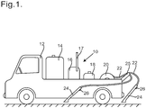
Figure 1 shows a side view of a pickup truck carrying a weed control apparatus of the invention; and -
Figure 2 shows a flow diagram of the weed control apparatus offigure 1 . - Referring to
figure 1 , aweed control apparatus 10 is carried on the back of apickup truck 12. Theapparatus 10 includes awater storage tank 14, a diesel-fuelledwater heater 16 with anexhaust pipe 17, a foaming-agent storage tank 18 and two hose reels 20 (only one is shown infigure 1 ) side-by-side near the rear of thepickup truck 12. Eachhose reel 20 carries aflexible hose 22, connected to alance 24 at its other end. Eachflexible hose 22 may be of length up to 50 m. A hose guide 25 projects from the rear of thepickup truck 12. In use the operators would pull out thehoses 22 from thehose reels 20 over thehose guide 25, pulling out sufficient length that they can reach the areas where weed killing is required, and the twolances 24 can then be operated separately by two operators. Eachlance 24 includes acontrol trigger 26. - In operation the foaming agent is introduced into water from the
water storage tank 14 that is heated by thewater heater 16, and is fed through thehoses 22 to thelances 24. When the operator actuates the control trigger 26, hot foam emerges from thelance 24. By way of example the hot foam may be at a temperature above 80°C, preferably above 90°C, for example at 96°C, as it emerges from thelance 24. The hot foam kills weeds with which it comes in contact. Hence the operators can control weeds over a large area, before having to move thepickup truck 12. In one example the flow rate of water is at least 9 L/min through eachhose 22, and may be 10 L/min or 12 L/min. - Referring now to
figure 2 , this shows a flow diagram for theweed control apparatus 10. Theweed control apparatus 10 operates under the control of acontroller 30 that may be a microprocessor, and which receives data from sensors, and controls operation of other components. Thewater storage tank 14 has alow level sensor 31 and anoverflow duct 32, and anoutflow duct 34 including atank valve 35 and awater filter 36. The filtered water is provided to apump 38, which pumps the water along aduct 39 to thewater heater 16 through aventuri injector 40. The foaming-agent storage tank 18 also has alow level sensor 42; and it is connected via afeed duct 43 including afilter 44 and asolenoid valve 45 to theventuri injector 40, so as water is pumped through theventuri injector 40 the foaming agent is sucked through thefeed duct 43 and mixed with the water, as long as thesolenoid valve 45 is open. - Between the
venturi injector 40 and thewater heater 16 there is a temperature sensor T2, aflow sensor 46 and apressure sensor 48, all connected to theduct 39, to monitor the flowing water. In addition there is apressure relief duct 50 connected to theduct 39, thepressure relief duct 50 incorporating a high-pressure relief valve 52, and connecting to awater return circuit 54 that leads back to thewater storage tank 14. Thewater return circuit 54 includes a heat exchanger in the form of aradiator 55 in combination with afan 56. - In operation, the signals from the temperature sensor T2, the
flow sensor 46 and thepressure sensor 48 are all provided to thecontroller 30. If there were to be a blockage in thewater heater 16, this would be detected either by an increase in pressure as sensed by thepressure sensor 48 or a decrease in flow as detected by theflow sensor 46; and in either case thecontroller 30 may stop the operation of thewater heater 16. The high-pressure relief valve 52 is arranged to open if the water pressure exceeds a safety limit (for example 40 bar = 4.0 MPa), so the pressure is relieved, and the excess water can return to thewater return circuit 54. - The water heater, in this example, 16 is fuelled by a liquid fuel such as diesel, stored in a
liquid fuel tank 60. Thetank 60 includes alow level sensor 62. The liquid fuel is supplied to thewater heater 16 through afuel supply duct 63 that includes a fuel/water separator 64. Thewater heater 16 heats the water in two stages, indicated by 66 and 67. The first stage 66 is arranged to raise the temperature of the water (at a normal flow rate, for example 12 L/min) by about 55° or 60°C, and operates continuously during normal operation. Thesecond stage 67 operates in a pulsed fashion, on a short time cycle, typically the cycle being less than 10 seconds. For example the time cycle may be 8 seconds; the second stage is pulsed on for a time period t1 which is a fraction of the time cycle. For example it may be pulsed on for 4 s (i.e. t1 = 4 s). The heat is generated by combustion of the liquid fuel, and the resulting exhaust gases are vented through theexhaust pipe 17. - The heated water emerges through an outflow or
outlet duct 70, and there is a temperature sensor T1 just downstream of thewater heater 16, which provide signals to thecontroller 30. Thecontroller 30 can control the temperature of the water, for example to maintain a substantially constant temperature of 102°C at the temperature sensor T1, by adjusting the time period t1 for which thesecond stage 67 is on, as the time period t1 is a continuous variable. Thecontroller 30, in the course of operation, ascertains what time period t1 is required to achieve the desired temperature at the temperature sensor T1, in accordance with the monitored temperature T2 of the inflowing water, so this can be used as an initial preset, for example when starting up, and then adjusted. - Downstream of the temperature sensor T1 is a
control valve 72 which is activated in response to the temperature measured by the temperature sensor T1, thecontrol valve 72 remaining closed until the temperature measured by the temperature sensor T1 reaches a preset value (such as 102°C). Upstream of thecontrol valve 72 there is apressure relief duct 74 connected to theoutflow duct 70, thepressure relief duct 74 incorporating a medium-pressure relief valve 75, and connecting to thewater return circuit 54 that leads back to thewater storage tank 14. The medium-pressure relief valve 75 is arranged to open if the water pressure exceeds a normal operating value (for example 20 bar = 2.0 MPa), so while thecontrol valve 72 is closed the heated water can return to thewater storage tank 14. - Downstream of the
control valve 72 is apressure sensor 80 connected to theoutflow duct 70, and downstream of thepressure sensor 80 theoutflow duct 70 divides into two outflow oroutlet ducts hose reels 20 and so to the twohoses 22. A short distance upstream of eachhose reel 20 is apressure relief duct 84 connected to therespective outflow duct pressure relief duct 84 incorporating a regulatingvalve 85, and connecting to thewater return circuit 54. In each case the regulatingvalve 85 is set so that as long as the water pressure has its normal operating value, for example 12 bar (1.2 MPa), a small amount of water, such as 10% of the flow through therespective outflow duct pressure relief duct 84; but that the regulatingvalve 85 will open to allow substantially all of the flow throughrespective outflow duct pressure relief duct 84 if the water pressure rises above the normal operating pressure. Thewater return circuit 54 includes aflow sensor 76 arranged to sense the flow of heated water, whether from thepressure relief duct 74 or from either of thepressure relief ducts 84, and to provide a signal to thecontroller 30. Hence under normal operation, if both thelances 24 are in use and the flow is the same through each of thelances 24, about 5% of the total water flow through thecontrol valve 72 passes through each of the regulatingvalves 85. - Thus, in use, the
controller 30 receives signals representing liquid levels from thelow level sensor 31, thelow level sensor 42 and alow level sensor 62; it receives signals representing temperature from the temperature sensors T1 and T2; it receives pressure signals from thepressure sensors flow sensors controller 30 can therefore provide control signals to thepump 38, to thesolenoid valve 45, thewater heater 16, thecontrol valve 72, and to thefan 56. When operation is initiated, thecontrol valve 72 is initially closed, and water is circulated by thepump 38 through thewater heater 16 and the medium-pressure relief valve 75. If the water temperature measured by the sensor T2 becomes warm, say above 35°C, thefan 56 may be activated to cool the recirculated heated water. When the heated water reaches the desired temperature, as measured by the temperature sensor T1, thecontrol valve 72 is opened, so the water can be dispensed by the operators through thelances 24. The water is mixed with air in thelance 24, and because of the presence of the foaming agent it forms a foam that blankets and kills the weeds. Typically the foam, as initially dispensed, is at a temperature of at least 90°C, for example 95°C. - If the operators turn off both the
lances 24, thepressure sensor 80 senses a large increase in pressure, and thecontroller 30 transitions thepump 38 and thewater heater 16 into a minimal power state. On the other hand, if only one operator turns off hislance 24, thepressure sensor 80 senses a smaller increase in pressure, and it may not be necessary to change the operation of thepump 38 or of thewater heater 16. In either case, if the water pressure in one or both of theoutflow ducts pressure relief duct 84 to thewater return circuit 54. If both thelances 24 have been turned off, and one or both are then switched on, then thepressure sensor 80 senses a sudden decrease in pressure, and thecontroller 30 restarts normal operation of thepump 38 and thewater heater 16. - This arrangement minimises the need to make sudden or abrupt changes to the operation of the
water heater 16, despite sudden changes in the overall flow rate as thelances 24 are turned on or off by the operators. The maximum acceptable temperature of the water from thewater storage tank 14, as measured by the temperature sensor T2, is 40°C; under those circumstances, since the first stage 66 raises the temperature by between 55° and 60°C, the water temperature after the first stage 66 is still below the required temperature. Using thefan 56 when hot water is being returned to thewater storage tank 14 enables much of the excess heat to be dissipated, so the water temperature in thewater storage tank 14 can be maintained below 40°, preferably below 35°C. - It will be appreciated that the
weed control apparatus 10 described above may be modified in various ways while remaining within the scope of the present invention, as defined by the claims. For example there might be threelances 24 attached to threehoses 22, instead of the twolances 24 shown in the figures. There might be a singlepressure relief duct 84 incorporating the regulatingvalve 85, and serving both theoutlet ducts heater 16 may be powered by a different liquid fuel, such as bio-ethanol, or may be powered electrically, for example from a battery.
Claims (12)
- An apparatus (10) suitable for controlling vegetation, the apparatus comprising a water storage tank (14); a heater (16); a pump (38) to transfer water from the water storage tank (14) to the heater (16); an injector (40) to introduce a foaming agent into the water; an outlet duct (70) to convey heated water from the heater (16); and an outlet hose (22) communicating with the outlet duct (70) and connected to a dispensing lance (24); characterised in that the apparatus is suitable for use by a plurality of operators, the apparatus comprising at least two outlet hoses (22) each communicating with the outlet duct (70) through a respective secondary outlet duct (70a; 70b) and each connected to a respective dispensing lance (24);
wherein the heater (16) is adapted to heat the water in at least two successive stages (66, 67), to an intermediate temperature and then to a final temperature, at least the second stage (67) of the heater (16) being activated in pulses, a temperature sensor (T1) downstream of the heater (16), and a controller (30), the frequency and/or duration of the pulses being adjustable to control the resultant temperature of the water;
and wherein upstream of each outlet hose (22) the respective secondary outlet duct (70a; 70b) communicates with a diversion valve (85), each diversion valve (85) connecting to a water return circuit (54) leading back to the water storage tank (14); and the water return circuit (54) includes a heat exchanger (55, 56). - An apparatus as claimed in claim 1 also comprising a control valve (72) adapted to open in response to signals from a sensor (T1) arranged to detect water temperature in the outlet duct (70), to ensure that water is supplied to the hoses (22) only when the water is at the desired temperature, and a pressure relief valve (75) communicating with the outlet duct (70) upstream of the control valve (72), and connecting to the water return circuit (54).
- An apparatus as claimed in claim 1 or claim 2, wherein the water return circuit (54) includes a flow sensor (76) to provide a signal to the controller (30).
- An apparatus as claimed in any one of the preceding claims wherein the heat exchanger in the water return circuit (54) is in the form of a radiator (55) in combination with a fan (56), and the controller (30) provides control signals to the fan (56) to cool the water passing through the heat exchanger (55).
- An apparatus as claimed in any one of the preceding claims also comprising a sensor (80) to detect if each one of the lances (24) is switched off, so there is no hot water emerging from the lances (24).
- An apparatus as claimed in claim 5 wherein the sensor (80) to detect if each one of the lances (24) is switched off is a pressure sensor (80) upstream of the hoses (22).
- An apparatus as claimed in any one of the preceding claims wherein each diversion valve (85) is a regulating valve.
- An apparatus as claimed in claim 7 wherein each diversion valve (85) is adapted such that at normal operating pressure when all of the dispensing lances (24) are in use, each diversion valve (85) allows no more than 10% of the water flow in the outlet duct (70) to pass through the diversion valve (85).
- An apparatus as claimed in claim 8 wherein at normal operating conditions when all of the dispensing lances (24) are in use, each diversion valve (85) allows between 2% and 8% of the water flow in the outlet duct (70) to pass through the diversion valve (85).
- An apparatus as claimed in any one of the preceding claims wherein the foaming agent comprises xanthan gum; a glutamic acid-based chelating agent; and a mixture of two different alkyl polyglucosides (APG).
- An apparatus as claimed in any one of the preceding claims that incorporates two lances (24), wherein the apparatus is mounted on a motor-vehicle (12).
- An apparatus as claimed in any one of the preceding claims wherein the heater (16) is liquid fuelled.
Applications Claiming Priority (2)
| Application Number | Priority Date | Filing Date | Title |
|---|---|---|---|
| GBGB1413214.6A GB201413214D0 (en) | 2014-07-25 | 2014-07-25 | Weed Control |
| PCT/GB2015/052081 WO2016012767A1 (en) | 2014-07-25 | 2015-07-17 | Weed control |
Publications (2)
| Publication Number | Publication Date |
|---|---|
| EP3171694A1 EP3171694A1 (en) | 2017-05-31 |
| EP3171694B1 true EP3171694B1 (en) | 2019-01-09 |
Family
ID=51587244
Family Applications (1)
| Application Number | Title | Priority Date | Filing Date |
|---|---|---|---|
| EP15741286.7A Not-in-force EP3171694B1 (en) | 2014-07-25 | 2015-07-17 | Weed control |
Country Status (5)
| Country | Link |
|---|---|
| US (1) | US10602735B2 (en) |
| EP (1) | EP3171694B1 (en) |
| CA (1) | CA2956234C (en) |
| GB (2) | GB201413214D0 (en) |
| WO (1) | WO2016012767A1 (en) |
Cited By (1)
| Publication number | Priority date | Publication date | Assignee | Title |
|---|---|---|---|---|
| DE102023209303A1 (en) * | 2023-09-22 | 2025-03-27 | Continental Engineering Services Gmbh | Plant treatment device |
Families Citing this family (7)
| Publication number | Priority date | Publication date | Assignee | Title |
|---|---|---|---|---|
| GB201620238D0 (en) * | 2016-11-29 | 2017-01-11 | Weeding Tech Ltd | Weed Control |
| GB201720478D0 (en) * | 2017-12-08 | 2018-01-24 | Weeding Tech Limited | Surfactant supply system |
| CA2991231A1 (en) * | 2018-01-08 | 2019-07-08 | X-Steam-Inator Agriculture Products Ltd. | Device and method for delivering steam onto and beneath a field surface |
| NL2027627B1 (en) * | 2021-02-23 | 2022-09-20 | Fortitude Holdings As | Apparatus and method for controlling weed growing on a ground surface |
| AT17613U1 (en) * | 2021-06-04 | 2022-08-15 | Michael Keckeis | Process for weed control with hot water |
| IT202200003935A1 (en) * | 2022-03-02 | 2023-09-02 | Spezia Srl | Mobile weeding/suckering equipment |
| DE102022000809A1 (en) | 2022-03-09 | 2023-09-14 | Elmo Gmbh | Area and/or body impact for vegetation control |
Family Cites Families (17)
| Publication number | Priority date | Publication date | Assignee | Title |
|---|---|---|---|---|
| US2345614A (en) * | 1942-04-24 | 1944-04-04 | Job F Malsbary | Cleaning machine |
| US5297730A (en) * | 1990-09-14 | 1994-03-29 | Aquaheat Technology, Inc. | Apparatus and method for controlling weeds and undergrowth |
| US5385106A (en) * | 1992-08-24 | 1995-01-31 | Langshaw; Eric | Hot water/steam weed killing system |
| ES2156870T3 (en) * | 1993-05-07 | 2001-08-01 | Waipuna Internat Ltd | METHOD AND APPLIANCE TO CONTROL VEGETATION. |
| US5575111A (en) * | 1995-09-28 | 1996-11-19 | Rajamannan; A. H. J. | Method of using hot air foam to kill vegetation and pests |
| WO2002007513A1 (en) * | 2000-07-17 | 2002-01-31 | Waipuna International Limited | Application of heat to control vegetation |
| US6435424B1 (en) * | 2000-07-27 | 2002-08-20 | Alto U.S. Inc. | Pressure washer with duty cycle temperature controller and method |
| NL1018458C2 (en) * | 2001-07-04 | 2003-01-08 | Waterkracht Bv | Weed killing method, comprises spraying hot water onto weeds, followed by deposition of insulating foam layer |
| NZ532571A (en) | 2001-09-27 | 2007-05-31 | Waipuna Systems Ltd Malta | Method and apparatus for weed control with hot foam of relatively low air content and relatively high "wet foam" content |
| US20050143259A1 (en) | 2003-12-29 | 2005-06-30 | Newson Richard J. | Thermal weed, fungal, insecticidal and sterilisation method |
| US7275699B2 (en) * | 2004-05-06 | 2007-10-02 | Thermal Science Technologies, Llc | Mobile pumping unit for dispensing insulating material in situ |
| US7939488B2 (en) * | 2008-08-26 | 2011-05-10 | The Clorox Company | Natural disinfecting cleaners |
| DE202009001969U1 (en) | 2009-03-16 | 2009-05-20 | Ipros Industrie Produkte Service Gmbh | Device for thermal vegetation control |
| US8038081B2 (en) * | 2009-08-13 | 2011-10-18 | Brendon Limited | Mobile power washer |
| NZ611257A (en) * | 2010-11-09 | 2014-12-24 | Weeding Technologies Ltd | Device for weed control |
| KR101250853B1 (en) | 2010-12-29 | 2013-04-04 | 이노크린 주식회사 | Environment-friendly herbicidal method and system thereof |
| US9628946B2 (en) * | 2012-06-29 | 2017-04-18 | Zoll Medical Corporation | Rescue services activation |
-
2014
- 2014-07-25 GB GBGB1413214.6A patent/GB201413214D0/en not_active Ceased
-
2015
- 2015-07-17 US US15/329,157 patent/US10602735B2/en active Active
- 2015-07-17 WO PCT/GB2015/052081 patent/WO2016012767A1/en not_active Ceased
- 2015-07-17 CA CA2956234A patent/CA2956234C/en active Active
- 2015-07-17 EP EP15741286.7A patent/EP3171694B1/en not_active Not-in-force
- 2015-07-17 GB GB1512606.3A patent/GB2530158A/en not_active Withdrawn
Non-Patent Citations (1)
| Title |
|---|
| None * |
Cited By (1)
| Publication number | Priority date | Publication date | Assignee | Title |
|---|---|---|---|---|
| DE102023209303A1 (en) * | 2023-09-22 | 2025-03-27 | Continental Engineering Services Gmbh | Plant treatment device |
Also Published As
| Publication number | Publication date |
|---|---|
| CA2956234A1 (en) | 2016-01-28 |
| GB201413214D0 (en) | 2014-09-10 |
| GB201512606D0 (en) | 2015-08-26 |
| EP3171694A1 (en) | 2017-05-31 |
| GB2530158A (en) | 2016-03-16 |
| US20170202203A1 (en) | 2017-07-20 |
| WO2016012767A1 (en) | 2016-01-28 |
| US10602735B2 (en) | 2020-03-31 |
| CA2956234C (en) | 2022-11-15 |
Similar Documents
| Publication | Publication Date | Title |
|---|---|---|
| CA2956234C (en) | Weed control | |
| EP2637498B1 (en) | Device for weed control | |
| US5385106A (en) | Hot water/steam weed killing system | |
| US11590374B2 (en) | Mobile compressed foam firefighting system | |
| WO2005038357A3 (en) | Method and apparatus for supplying refrigerant fluid | |
| CN104898738B (en) | Constant temperature heating control method for electronic toilet | |
| US4046321A (en) | High pressure spray cleaning head | |
| WO2008001300A3 (en) | A liquid droplet spray cleaning system for teeth with temperature and filter controls | |
| DE102018121922A1 (en) | Hot water cleaning device and method for operating a hot water cleaning device | |
| US20110250547A1 (en) | Burner system and a method of control | |
| CN111556708A (en) | Apparatus and method for delivering steam above and below a field surface | |
| DE102006062069A1 (en) | Cooking appliance steam generating device with at least one instantaneous water heater | |
| NL1015139C2 (en) | Method and device for cleaning with water. | |
| KR200367153Y1 (en) | Hot Water Providing Device | |
| US20240224980A9 (en) | Apparatus and method for controlling weed growing on a ground surface | |
| JP2016146813A (en) | Hot water pest control device | |
| NL1018458C2 (en) | Weed killing method, comprises spraying hot water onto weeds, followed by deposition of insulating foam layer | |
| US20060243324A1 (en) | Automatic start additive injection system for fire-fighting vehicles | |
| CN208779683U (en) | A commercial instant type anti-dry water heater | |
| JP2006288816A (en) | Mist sauna system | |
| JPH08290024A (en) | Purifier for bathtub hot water | |
| JP2004263422A (en) | Toilet equipment | |
| IT202000018688A1 (en) | "RECIRCULATED WATER HIGH PRESSURE CLEANER" | |
| NO172332B (en) | PROCEDURE FOR APPLYING LIQUIDS ON OBJECTS | |
| JP2005342683A (en) | Apparatus for monitoring clogging of nozzle for spraying asphalt emulsion |
Legal Events
| Date | Code | Title | Description |
|---|---|---|---|
| STAA | Information on the status of an ep patent application or granted ep patent |
Free format text: STATUS: THE INTERNATIONAL PUBLICATION HAS BEEN MADE |
|
| PUAI | Public reference made under article 153(3) epc to a published international application that has entered the european phase |
Free format text: ORIGINAL CODE: 0009012 |
|
| STAA | Information on the status of an ep patent application or granted ep patent |
Free format text: STATUS: REQUEST FOR EXAMINATION WAS MADE |
|
| 17P | Request for examination filed |
Effective date: 20170207 |
|
| AK | Designated contracting states |
Kind code of ref document: A1 Designated state(s): AL AT BE BG CH CY CZ DE DK EE ES FI FR GB GR HR HU IE IS IT LI LT LU LV MC MK MT NL NO PL PT RO RS SE SI SK SM TR |
|
| AX | Request for extension of the european patent |
Extension state: BA ME |
|
| DAV | Request for validation of the european patent (deleted) | ||
| DAX | Request for extension of the european patent (deleted) | ||
| GRAP | Despatch of communication of intention to grant a patent |
Free format text: ORIGINAL CODE: EPIDOSNIGR1 |
|
| STAA | Information on the status of an ep patent application or granted ep patent |
Free format text: STATUS: GRANT OF PATENT IS INTENDED |
|
| INTG | Intention to grant announced |
Effective date: 20180801 |
|
| GRAS | Grant fee paid |
Free format text: ORIGINAL CODE: EPIDOSNIGR3 |
|
| GRAA | (expected) grant |
Free format text: ORIGINAL CODE: 0009210 |
|
| STAA | Information on the status of an ep patent application or granted ep patent |
Free format text: STATUS: THE PATENT HAS BEEN GRANTED |
|
| AK | Designated contracting states |
Kind code of ref document: B1 Designated state(s): AL AT BE BG CH CY CZ DE DK EE ES FI FR GB GR HR HU IE IS IT LI LT LU LV MC MK MT NL NO PL PT RO RS SE SI SK SM TR |
|
| REG | Reference to a national code |
Ref country code: GB Ref legal event code: FG4D |
|
| REG | Reference to a national code |
Ref country code: CH Ref legal event code: EP Ref country code: AT Ref legal event code: REF Ref document number: 1086190 Country of ref document: AT Kind code of ref document: T Effective date: 20190115 |
|
| REG | Reference to a national code |
Ref country code: IE Ref legal event code: FG4D |
|
| REG | Reference to a national code |
Ref country code: DE Ref legal event code: R096 Ref document number: 602015023210 Country of ref document: DE |
|
| REG | Reference to a national code |
Ref country code: CH Ref legal event code: NV Representative=s name: SERVOPATENT GMBH, CH Ref country code: CH Ref legal event code: PCOW Free format text: NEW ADDRESS: UNIT 2, WESTPINT TRADING ESTATE ALLIANCE ROAD, LONDON W3 0RA (GB) |
|
| RAP2 | Party data changed (patent owner data changed or rights of a patent transferred) |
Owner name: WEEDING TECHNOLOGIES LIMITED |
|
| REG | Reference to a national code |
Ref country code: NL Ref legal event code: MP Effective date: 20190109 |
|
| REG | Reference to a national code |
Ref country code: LT Ref legal event code: MG4D |
|
| PG25 | Lapsed in a contracting state [announced via postgrant information from national office to epo] |
Ref country code: NL Free format text: LAPSE BECAUSE OF FAILURE TO SUBMIT A TRANSLATION OF THE DESCRIPTION OR TO PAY THE FEE WITHIN THE PRESCRIBED TIME-LIMIT Effective date: 20190109 |
|
| REG | Reference to a national code |
Ref country code: AT Ref legal event code: MK05 Ref document number: 1086190 Country of ref document: AT Kind code of ref document: T Effective date: 20190109 |
|
| PG25 | Lapsed in a contracting state [announced via postgrant information from national office to epo] |
Ref country code: NO Free format text: LAPSE BECAUSE OF FAILURE TO SUBMIT A TRANSLATION OF THE DESCRIPTION OR TO PAY THE FEE WITHIN THE PRESCRIBED TIME-LIMIT Effective date: 20190409 Ref country code: PT Free format text: LAPSE BECAUSE OF FAILURE TO SUBMIT A TRANSLATION OF THE DESCRIPTION OR TO PAY THE FEE WITHIN THE PRESCRIBED TIME-LIMIT Effective date: 20190509 Ref country code: FI Free format text: LAPSE BECAUSE OF FAILURE TO SUBMIT A TRANSLATION OF THE DESCRIPTION OR TO PAY THE FEE WITHIN THE PRESCRIBED TIME-LIMIT Effective date: 20190109 Ref country code: SE Free format text: LAPSE BECAUSE OF FAILURE TO SUBMIT A TRANSLATION OF THE DESCRIPTION OR TO PAY THE FEE WITHIN THE PRESCRIBED TIME-LIMIT Effective date: 20190109 Ref country code: PL Free format text: LAPSE BECAUSE OF FAILURE TO SUBMIT A TRANSLATION OF THE DESCRIPTION OR TO PAY THE FEE WITHIN THE PRESCRIBED TIME-LIMIT Effective date: 20190109 Ref country code: ES Free format text: LAPSE BECAUSE OF FAILURE TO SUBMIT A TRANSLATION OF THE DESCRIPTION OR TO PAY THE FEE WITHIN THE PRESCRIBED TIME-LIMIT Effective date: 20190109 Ref country code: LT Free format text: LAPSE BECAUSE OF FAILURE TO SUBMIT A TRANSLATION OF THE DESCRIPTION OR TO PAY THE FEE WITHIN THE PRESCRIBED TIME-LIMIT Effective date: 20190109 |
|
| PG25 | Lapsed in a contracting state [announced via postgrant information from national office to epo] |
Ref country code: HR Free format text: LAPSE BECAUSE OF FAILURE TO SUBMIT A TRANSLATION OF THE DESCRIPTION OR TO PAY THE FEE WITHIN THE PRESCRIBED TIME-LIMIT Effective date: 20190109 Ref country code: RS Free format text: LAPSE BECAUSE OF FAILURE TO SUBMIT A TRANSLATION OF THE DESCRIPTION OR TO PAY THE FEE WITHIN THE PRESCRIBED TIME-LIMIT Effective date: 20190109 Ref country code: LV Free format text: LAPSE BECAUSE OF FAILURE TO SUBMIT A TRANSLATION OF THE DESCRIPTION OR TO PAY THE FEE WITHIN THE PRESCRIBED TIME-LIMIT Effective date: 20190109 Ref country code: IS Free format text: LAPSE BECAUSE OF FAILURE TO SUBMIT A TRANSLATION OF THE DESCRIPTION OR TO PAY THE FEE WITHIN THE PRESCRIBED TIME-LIMIT Effective date: 20190509 Ref country code: GR Free format text: LAPSE BECAUSE OF FAILURE TO SUBMIT A TRANSLATION OF THE DESCRIPTION OR TO PAY THE FEE WITHIN THE PRESCRIBED TIME-LIMIT Effective date: 20190410 Ref country code: BG Free format text: LAPSE BECAUSE OF FAILURE TO SUBMIT A TRANSLATION OF THE DESCRIPTION OR TO PAY THE FEE WITHIN THE PRESCRIBED TIME-LIMIT Effective date: 20190409 |
|
| REG | Reference to a national code |
Ref country code: DE Ref legal event code: R097 Ref document number: 602015023210 Country of ref document: DE |
|
| PG25 | Lapsed in a contracting state [announced via postgrant information from national office to epo] |
Ref country code: IT Free format text: LAPSE BECAUSE OF FAILURE TO SUBMIT A TRANSLATION OF THE DESCRIPTION OR TO PAY THE FEE WITHIN THE PRESCRIBED TIME-LIMIT Effective date: 20190109 Ref country code: RO Free format text: LAPSE BECAUSE OF FAILURE TO SUBMIT A TRANSLATION OF THE DESCRIPTION OR TO PAY THE FEE WITHIN THE PRESCRIBED TIME-LIMIT Effective date: 20190109 Ref country code: DK Free format text: LAPSE BECAUSE OF FAILURE TO SUBMIT A TRANSLATION OF THE DESCRIPTION OR TO PAY THE FEE WITHIN THE PRESCRIBED TIME-LIMIT Effective date: 20190109 Ref country code: EE Free format text: LAPSE BECAUSE OF FAILURE TO SUBMIT A TRANSLATION OF THE DESCRIPTION OR TO PAY THE FEE WITHIN THE PRESCRIBED TIME-LIMIT Effective date: 20190109 Ref country code: AT Free format text: LAPSE BECAUSE OF FAILURE TO SUBMIT A TRANSLATION OF THE DESCRIPTION OR TO PAY THE FEE WITHIN THE PRESCRIBED TIME-LIMIT Effective date: 20190109 Ref country code: AL Free format text: LAPSE BECAUSE OF FAILURE TO SUBMIT A TRANSLATION OF THE DESCRIPTION OR TO PAY THE FEE WITHIN THE PRESCRIBED TIME-LIMIT Effective date: 20190109 Ref country code: CZ Free format text: LAPSE BECAUSE OF FAILURE TO SUBMIT A TRANSLATION OF THE DESCRIPTION OR TO PAY THE FEE WITHIN THE PRESCRIBED TIME-LIMIT Effective date: 20190109 Ref country code: SK Free format text: LAPSE BECAUSE OF FAILURE TO SUBMIT A TRANSLATION OF THE DESCRIPTION OR TO PAY THE FEE WITHIN THE PRESCRIBED TIME-LIMIT Effective date: 20190109 |
|
| PLBE | No opposition filed within time limit |
Free format text: ORIGINAL CODE: 0009261 |
|
| STAA | Information on the status of an ep patent application or granted ep patent |
Free format text: STATUS: NO OPPOSITION FILED WITHIN TIME LIMIT |
|
| PG25 | Lapsed in a contracting state [announced via postgrant information from national office to epo] |
Ref country code: SM Free format text: LAPSE BECAUSE OF FAILURE TO SUBMIT A TRANSLATION OF THE DESCRIPTION OR TO PAY THE FEE WITHIN THE PRESCRIBED TIME-LIMIT Effective date: 20190109 |
|
| 26N | No opposition filed |
Effective date: 20191010 |
|
| PG25 | Lapsed in a contracting state [announced via postgrant information from national office to epo] |
Ref country code: MC Free format text: LAPSE BECAUSE OF FAILURE TO SUBMIT A TRANSLATION OF THE DESCRIPTION OR TO PAY THE FEE WITHIN THE PRESCRIBED TIME-LIMIT Effective date: 20190109 Ref country code: SI Free format text: LAPSE BECAUSE OF FAILURE TO SUBMIT A TRANSLATION OF THE DESCRIPTION OR TO PAY THE FEE WITHIN THE PRESCRIBED TIME-LIMIT Effective date: 20190109 |
|
| REG | Reference to a national code |
Ref country code: CH Ref legal event code: PL |
|
| PG25 | Lapsed in a contracting state [announced via postgrant information from national office to epo] |
Ref country code: TR Free format text: LAPSE BECAUSE OF FAILURE TO SUBMIT A TRANSLATION OF THE DESCRIPTION OR TO PAY THE FEE WITHIN THE PRESCRIBED TIME-LIMIT Effective date: 20190109 |
|
| PG25 | Lapsed in a contracting state [announced via postgrant information from national office to epo] |
Ref country code: LU Free format text: LAPSE BECAUSE OF NON-PAYMENT OF DUE FEES Effective date: 20190717 Ref country code: LI Free format text: LAPSE BECAUSE OF NON-PAYMENT OF DUE FEES Effective date: 20190731 Ref country code: CH Free format text: LAPSE BECAUSE OF NON-PAYMENT OF DUE FEES Effective date: 20190731 |
|
| PG25 | Lapsed in a contracting state [announced via postgrant information from national office to epo] |
Ref country code: IE Free format text: LAPSE BECAUSE OF NON-PAYMENT OF DUE FEES Effective date: 20190717 |
|
| PG25 | Lapsed in a contracting state [announced via postgrant information from national office to epo] |
Ref country code: CY Free format text: LAPSE BECAUSE OF FAILURE TO SUBMIT A TRANSLATION OF THE DESCRIPTION OR TO PAY THE FEE WITHIN THE PRESCRIBED TIME-LIMIT Effective date: 20190109 |
|
| PG25 | Lapsed in a contracting state [announced via postgrant information from national office to epo] |
Ref country code: HU Free format text: LAPSE BECAUSE OF FAILURE TO SUBMIT A TRANSLATION OF THE DESCRIPTION OR TO PAY THE FEE WITHIN THE PRESCRIBED TIME-LIMIT; INVALID AB INITIO Effective date: 20150717 |
|
| PG25 | Lapsed in a contracting state [announced via postgrant information from national office to epo] |
Ref country code: MT Free format text: LAPSE BECAUSE OF FAILURE TO SUBMIT A TRANSLATION OF THE DESCRIPTION OR TO PAY THE FEE WITHIN THE PRESCRIBED TIME-LIMIT Effective date: 20190717 |
|
| PG25 | Lapsed in a contracting state [announced via postgrant information from national office to epo] |
Ref country code: MK Free format text: LAPSE BECAUSE OF FAILURE TO SUBMIT A TRANSLATION OF THE DESCRIPTION OR TO PAY THE FEE WITHIN THE PRESCRIBED TIME-LIMIT Effective date: 20190109 |
|
| PGFP | Annual fee paid to national office [announced via postgrant information from national office to epo] |
Ref country code: GB Payment date: 20230728 Year of fee payment: 9 |
|
| PGFP | Annual fee paid to national office [announced via postgrant information from national office to epo] |
Ref country code: FR Payment date: 20230725 Year of fee payment: 9 Ref country code: DE Payment date: 20230725 Year of fee payment: 9 Ref country code: BE Payment date: 20230724 Year of fee payment: 9 |
|
| REG | Reference to a national code |
Ref country code: DE Ref legal event code: R119 Ref document number: 602015023210 Country of ref document: DE |
|
| GBPC | Gb: european patent ceased through non-payment of renewal fee |
Effective date: 20240717 |
|
| PG25 | Lapsed in a contracting state [announced via postgrant information from national office to epo] |
Ref country code: DE Free format text: LAPSE BECAUSE OF NON-PAYMENT OF DUE FEES Effective date: 20250201 |
|
| PG25 | Lapsed in a contracting state [announced via postgrant information from national office to epo] |
Ref country code: BE Free format text: LAPSE BECAUSE OF NON-PAYMENT OF DUE FEES Effective date: 20240731 |
|
| PG25 | Lapsed in a contracting state [announced via postgrant information from national office to epo] |
Ref country code: FR Free format text: LAPSE BECAUSE OF NON-PAYMENT OF DUE FEES Effective date: 20240731 |
|
| PG25 | Lapsed in a contracting state [announced via postgrant information from national office to epo] |
Ref country code: GB Free format text: LAPSE BECAUSE OF NON-PAYMENT OF DUE FEES Effective date: 20240717 |
|
| REG | Reference to a national code |
Ref country code: BE Ref legal event code: MM Effective date: 20240731 |