EP3171463A1 - Connector having a slide for facilitating connection and a cable guide cover - Google Patents
Connector having a slide for facilitating connection and a cable guide cover Download PDFInfo
- Publication number
- EP3171463A1 EP3171463A1 EP16199668.1A EP16199668A EP3171463A1 EP 3171463 A1 EP3171463 A1 EP 3171463A1 EP 16199668 A EP16199668 A EP 16199668A EP 3171463 A1 EP3171463 A1 EP 3171463A1
- Authority
- EP
- European Patent Office
- Prior art keywords
- slide
- cable guide
- guide cover
- connector
- housing
- Prior art date
- Legal status (The legal status is an assumption and is not a legal conclusion. Google has not performed a legal analysis and makes no representation as to the accuracy of the status listed.)
- Granted
Links
Images

Classifications
-
- H—ELECTRICITY
- H01—ELECTRIC ELEMENTS
- H01R—ELECTRICALLY-CONDUCTIVE CONNECTIONS; STRUCTURAL ASSOCIATIONS OF A PLURALITY OF MUTUALLY-INSULATED ELECTRICAL CONNECTING ELEMENTS; COUPLING DEVICES; CURRENT COLLECTORS
- H01R13/00—Details of coupling devices of the kinds covered by groups H01R12/70 or H01R24/00 - H01R33/00
- H01R13/62—Means for facilitating engagement or disengagement of coupling parts or for holding them in engagement
- H01R13/629—Additional means for facilitating engagement or disengagement of coupling parts, e.g. aligning or guiding means, levers, gas pressure electrical locking indicators, manufacturing tolerances
- H01R13/62933—Comprising exclusively pivoting lever
- H01R13/62955—Pivoting lever comprising supplementary/additional locking means
-
- H—ELECTRICITY
- H01—ELECTRIC ELEMENTS
- H01R—ELECTRICALLY-CONDUCTIVE CONNECTIONS; STRUCTURAL ASSOCIATIONS OF A PLURALITY OF MUTUALLY-INSULATED ELECTRICAL CONNECTING ELEMENTS; COUPLING DEVICES; CURRENT COLLECTORS
- H01R13/00—Details of coupling devices of the kinds covered by groups H01R12/70 or H01R24/00 - H01R33/00
- H01R13/62—Means for facilitating engagement or disengagement of coupling parts or for holding them in engagement
- H01R13/629—Additional means for facilitating engagement or disengagement of coupling parts, e.g. aligning or guiding means, levers, gas pressure electrical locking indicators, manufacturing tolerances
- H01R13/62977—Pivoting levers actuating linearly camming means
-
- H—ELECTRICITY
- H01—ELECTRIC ELEMENTS
- H01R—ELECTRICALLY-CONDUCTIVE CONNECTIONS; STRUCTURAL ASSOCIATIONS OF A PLURALITY OF MUTUALLY-INSULATED ELECTRICAL CONNECTING ELEMENTS; COUPLING DEVICES; CURRENT COLLECTORS
- H01R13/00—Details of coupling devices of the kinds covered by groups H01R12/70 or H01R24/00 - H01R33/00
- H01R13/46—Bases; Cases
- H01R13/502—Bases; Cases composed of different pieces
-
- H—ELECTRICITY
- H01—ELECTRIC ELEMENTS
- H01R—ELECTRICALLY-CONDUCTIVE CONNECTIONS; STRUCTURAL ASSOCIATIONS OF A PLURALITY OF MUTUALLY-INSULATED ELECTRICAL CONNECTING ELEMENTS; COUPLING DEVICES; CURRENT COLLECTORS
- H01R13/00—Details of coupling devices of the kinds covered by groups H01R12/70 or H01R24/00 - H01R33/00
- H01R13/46—Bases; Cases
- H01R13/516—Means for holding or embracing insulating body, e.g. casing, hoods
-
- H—ELECTRICITY
- H01—ELECTRIC ELEMENTS
- H01R—ELECTRICALLY-CONDUCTIVE CONNECTIONS; STRUCTURAL ASSOCIATIONS OF A PLURALITY OF MUTUALLY-INSULATED ELECTRICAL CONNECTING ELEMENTS; COUPLING DEVICES; CURRENT COLLECTORS
- H01R13/00—Details of coupling devices of the kinds covered by groups H01R12/70 or H01R24/00 - H01R33/00
- H01R13/62—Means for facilitating engagement or disengagement of coupling parts or for holding them in engagement
- H01R13/629—Additional means for facilitating engagement or disengagement of coupling parts, e.g. aligning or guiding means, levers, gas pressure electrical locking indicators, manufacturing tolerances
- H01R13/62933—Comprising exclusively pivoting lever
-
- H—ELECTRICITY
- H01—ELECTRIC ELEMENTS
- H01R—ELECTRICALLY-CONDUCTIVE CONNECTIONS; STRUCTURAL ASSOCIATIONS OF A PLURALITY OF MUTUALLY-INSULATED ELECTRICAL CONNECTING ELEMENTS; COUPLING DEVICES; CURRENT COLLECTORS
- H01R13/00—Details of coupling devices of the kinds covered by groups H01R12/70 or H01R24/00 - H01R33/00
- H01R13/62—Means for facilitating engagement or disengagement of coupling parts or for holding them in engagement
- H01R13/629—Additional means for facilitating engagement or disengagement of coupling parts, e.g. aligning or guiding means, levers, gas pressure electrical locking indicators, manufacturing tolerances
- H01R13/62933—Comprising exclusively pivoting lever
- H01R13/62938—Pivoting lever comprising own camming means
-
- H—ELECTRICITY
- H01—ELECTRIC ELEMENTS
- H01R—ELECTRICALLY-CONDUCTIVE CONNECTIONS; STRUCTURAL ASSOCIATIONS OF A PLURALITY OF MUTUALLY-INSULATED ELECTRICAL CONNECTING ELEMENTS; COUPLING DEVICES; CURRENT COLLECTORS
- H01R13/00—Details of coupling devices of the kinds covered by groups H01R12/70 or H01R24/00 - H01R33/00
- H01R13/58—Means for relieving strain on wire connection, e.g. cord grip, for avoiding loosening of connections between wires and terminals within a coupling device terminating a cable
- H01R13/5804—Means for relieving strain on wire connection, e.g. cord grip, for avoiding loosening of connections between wires and terminals within a coupling device terminating a cable comprising a separate cable clamping part
- H01R13/5812—Means for relieving strain on wire connection, e.g. cord grip, for avoiding loosening of connections between wires and terminals within a coupling device terminating a cable comprising a separate cable clamping part the cable clamping being achieved by mounting the separate part on the housing of the coupling device
-
- H—ELECTRICITY
- H01—ELECTRIC ELEMENTS
- H01R—ELECTRICALLY-CONDUCTIVE CONNECTIONS; STRUCTURAL ASSOCIATIONS OF A PLURALITY OF MUTUALLY-INSULATED ELECTRICAL CONNECTING ELEMENTS; COUPLING DEVICES; CURRENT COLLECTORS
- H01R13/00—Details of coupling devices of the kinds covered by groups H01R12/70 or H01R24/00 - H01R33/00
- H01R13/62—Means for facilitating engagement or disengagement of coupling parts or for holding them in engagement
- H01R13/629—Additional means for facilitating engagement or disengagement of coupling parts, e.g. aligning or guiding means, levers, gas pressure electrical locking indicators, manufacturing tolerances
- H01R13/62905—Additional means for facilitating engagement or disengagement of coupling parts, e.g. aligning or guiding means, levers, gas pressure electrical locking indicators, manufacturing tolerances comprising a camming member
- H01R13/62922—Pair of camming plates
-
- H—ELECTRICITY
- H01—ELECTRIC ELEMENTS
- H01R—ELECTRICALLY-CONDUCTIVE CONNECTIONS; STRUCTURAL ASSOCIATIONS OF A PLURALITY OF MUTUALLY-INSULATED ELECTRICAL CONNECTING ELEMENTS; COUPLING DEVICES; CURRENT COLLECTORS
- H01R13/00—Details of coupling devices of the kinds covered by groups H01R12/70 or H01R24/00 - H01R33/00
- H01R13/62—Means for facilitating engagement or disengagement of coupling parts or for holding them in engagement
- H01R13/629—Additional means for facilitating engagement or disengagement of coupling parts, e.g. aligning or guiding means, levers, gas pressure electrical locking indicators, manufacturing tolerances
- H01R13/62933—Comprising exclusively pivoting lever
- H01R13/62944—Pivoting lever comprising gear teeth
Definitions
- the invention relates to the field of connector technology, and in particular that of automotive connector technology.
- Connectors are used to transmit signals or electrical energy between cables, devices (computer, lighting, etc.) or motors.
- electrical connectors comprise electrical contacts in a greater or smaller number, or of a larger or smaller size.
- the contact force must be sufficiently high in order to ensure good electrical conduction between male and female contacts. For this reason, and in particular if contacts are of relatively large size, for example as a result of being connected to a source of an electrical power supply, the insertion force of the male contact into the female contact may become relatively large.
- certain connectors are equipped with a device for facilitating the connection, or for assisting with the coupling, of a connector to a counter connector.
- a device for facilitating the connection may comprise a sliding drawer, or slide, and a rotating lever, for example.
- a system of gearing having teeth on a part of the lever which is caused to rotate when the lever is actuated, as well as a rack on the slide, makes it possible to displace the slide in translation.
- a ramp device on the slide and a pinion device on the counter connector makes it possible to drive the counter connector in order to couple it to the connector.
- the connector may be equipped with a cable guide cover in order to guide and maintain the cables that are electrically connected to the contacts fitted in the connector.
- the lever may be rotatably mounted on said cable guide cover.
- the teeth of the lever may deviate too far from the rack of the slide, which may give rise to blockages or malfunctioning of the assembly of the device for facilitating the connection. It is also possible for the cable guide cover to become detached from the housing.
- this solution makes it necessary to position this portion in a relatively central manner on the housing and, for this reason, limits the potentially useful length of the lever, for a given size of the connector and its lever, and, consequently, increases the force to be applied to the lever in order to couple the connector to the counter connector.
- One aim of the invention is to mitigate at least partially the problems mentioned above.
- a connector comprising a housing, a lever for facilitating the connection, a slide for facilitating the connection and a cable guide cover are proposed to this end.
- the lever is rotatably mounted on the cable guide cover, about an axis of rotation. The rotation of the lever thus takes place essentially between a pre-coupling position, in which a counter connector may be coupled to the connector, and a locking position, in which the connector and the counter connector are locked together.
- the slide is movably mounted on the housing. It is driven via the lever in translation in a direction that is essentially perpendicular to the axis of rotation of the lever. Said translation takes place essentially between an initial position, corresponding to the pre-coupling position of the lever, and a final position, corresponding to the locking position of the lever. In the course of its translation, the slide cooperates with the counter connector in order to couple the counter connector to the connector.
- the slide comprises means of restraining the cable guide cover, which means are displaced together with the slide and move into engagement with the cable guide cover in the course of rotation of the lever.
- the chain of the dimensions and of the tolerances between the teeth of the lever and the rack of the slide is reduced in this way because, according to the invention, a direct interaction exists between the cable guide cover and the slide in its final position, but without passing via the intermediary of the housing.
- the risk of failure in the interaction between the teeth of the lever and the rack of the slide, and of blockage of the device for assisting with the coupling which may result therefrom, is then reduced.
- This arrangement likewise makes it possible to make the cable guide cover non-removable if the lever is in the locking position. In fact, it is first necessary for the slide to release the cable guide cover (although the lever should not be in the locking position) in order to disassemble it from the housing. It is thus no longer possible to lose the cable guide cover or to disassemble it inadvertently in the event of incorrect operation.
- connection assembly comprising a connector according to one of the preceding claims and a counter connector, in which
- connection assembly 100 depicted in figure 1 comprises a connector 1 and a counter connector 2.
- the connector 1 and the counter connector 2 are positioned with their coupling faces facing one another, although the connector 1 and the counter connector 2 are not coupled together.
- the connector 1 and the counter connector 2 In order to be coupled and connected, the connector 1 and the counter connector 2 must be displaced one towards the other, in a direction of coupling A, shown vertically in the figures, and the counter connector 2 must then be engaged, at least in part, in the connector 1 by causing them to continue to be displaced in said direction of coupling A.
- the connector 1 comprises in particular a housing 3, a lever 4 for facilitating the connection, two slides 5 likewise making a contribution to facilitating the connection and a cable guide cover 6.
- the housing 3, the lever 4 for facilitating the connection, the two slides 5 and the cable guide cover 6 are moulded in a plastic material.
- the connector 1 likewise comprises, albeit not illustrated here, female contacts or clips that are constituted by a metallic conductor.
- the counter connector 2 comprises male contacts or tongues (not depicted in the figures) that are constituted by a metallic conductor.
- the lever 4 is rotatably mounted on the cable guide cover 6, about an axis of rotation R, perpendicular to the direction of coupling A.
- the slides 5 are mounted in translation, in a longitudinal direction L, simultaneously perpendicular to the directions of coupling A and rotation R, on the longitudinal flanks 7 of the housing 3.
- lever 4 is in the pre-coupling position in order to permit the coupling of the connector 1 to the counter connector 2, and the slides 6 are in the initial position.
- connection assembly 100 is depicted with the connector 1 and the counter connector 2 coupled, that is to say attached mechanically to one another and connected electrically.
- the connector 1 has its lever 4 in the locked position, and the slides 5 are in the final position.
- the lever 4 exhibits a generally "U"-shaped form with two branches 7, each respectively constituting a lever arm.
- One extremity of each of said branches is articulated on one face of the cable guide cover 6 via the intermediary of an articulation portion 8, whereas the other two extremities are connected via a handle 9.
- the cable guide cover 6 is defined as having a front portion 11 that is opposite, relative to the longitudinal direction L, to a rear portion 12 provided with an opening 13 for the passage of cables (not depicted in the figures) that are electrically connected to the contacts fitted in the housing 3.
- the cables exiting via the opening 13 may be attached with one or a plurality of cable ties to a collar 14. Consequently, a considerable pulling force may possibly be applied to the rear portion 12 of the cable guide cover 6, which pulling force could cause the cable guide cover 6, in particular at the level of its front portion 11, to become disassociated from the housing 2. It is advantageous, therefore, to dispose robust and effective means in order to maintain the cable guide cover 6 on the housing 3 and, indirectly, the lever 4 in engagement with the slides 5, as described below in a more detailed manner.
- the cable guide cover 6 comprises fixing feet 15 that are integrally formed with the latter. They each extend respectively, in the direction of coupling A, from an edge of the cable guide cover 6 parallel to the longitudinal direction L. They are situated in the area of the front portion 11 of the cable guide cover 6.
- the fixing feet 15 comprise a groove 16 that is open towards the exterior of the connector 1 and extend longitudinally parallel to the longitudinal direction L, when the cable guide cover 6 is fixed to the housing 3.
- the cable guide cover 6 comprises means of anchoring 17 situated in the area of the rear portion 12 in proximity to the opening 13 (in figure 3A , the lever 4 not being depicted for greater clarity, although it is normally present in the course of this phase of assembling the connector 1).
- Said means of anchoring 17 are present, for example, in the form of a beam that is integrally formed with the rest of the cable guide cover 6. Said beam is engaged in a throat provided in the edge 18 extending the rear face 19 of the housing 3.
- the front portion 11 of the cable guide cover 6 is raised in relation to the housing 3, in such a way as to permit the articulation portions 8 of the lever 4 to be inserted into a slot provided on the top of the slides 5 (see figure 3B ).
- the front portion 11 of the cable guide cover 6 is lowered onto the housing 3.
- the cable guide cover 6 is maintained in this position with the help of a hook 20 engaging in a notch 21 produced on a foot 22 that is integrally formed with the housing 3 (see figures 1 and 2 ).
- the fixing feet 15 are each brought respectively into a recess 23 provided in the housing 3 (see Figure 3A ).
- the fixing feet 15 are then present in a zone of the housing 3 that is covered by the slide 5, when the latter is in the final position (see figures 4B and 4C , for example).
- the respective grooves 16 of the fixing feet 15 are essentially present in the extension of a similar groove 24 provided on each of the longitudinal lateral faces of the housing 3, in proximity to an upper edge of the latter.
- another groove 25, parallel to the preceding groove 24, is likewise provided on each of the lateral longitudinal faces of the housing 3 in proximity to a lower edge of the latter.
- Each slide 5 is present in the form of a plate having means of restraining the cable guide cover 6.
- said means of restraining the cable guide cover 6 comprise an upper rib 26 parallel to the longitudinal direction L.
- Each slide 5 may likewise comprise a lower rib 27 that is likewise parallel to the longitudinal direction L.
- the lower ribs 27 and the upper ribs 26 are moulded together with each slide 5.
- Each slide 5 is then mounted on a longitudinal lateral face of the housing 3 with its lower ribs 27 and its upper ribs 26, each engaged respectively in a groove 24, 25 provided in a longitudinal lateral face of the housing 3.
- the grooves 24 and 25 extend to either side of the recesses 23 for the fixing feet 15, each slide being maintained accurately and in a robust manner for the major part of their length, on the housing 3.
- each slide 5 is brought by a system of gearing from its initial position depicted in figure 4A as far as its final position depicted in figure 4C , by passing through an intermediate position depicted in figure 4B .
- the cable guide cover 6 may be disassembled from the housing 3 by releasing the hook 20 from the notch 21 and by disengaging the beam from the edge 18.
- the latter cover the fixing feet 15 and their upper rib 26 is engaged in the groove 16 of a fixing foot 15.
- each fixing foot 15 comprises a lower ramp 28 cooperating with a slide 5 when the latter is in the final position. Said lower ramp 28 draws the slide 5 towards the cable guide cover 6. Conversely, each fixing foot 15 comprises an upper ramp 29 cooperating with a slide 5 when the latter is in the final position. Said ramp 29 draws the cable guide cover 6 towards the housing 3 when the slide 5 is in the final position.
- the lower ramps 26 and the upper ramps 29 assist the maintenance of the slides 5 by the ribs 26, 27 and grooves 24, 25 and guide the slides 5 in a better-adapted manner, in order to achieve a more accurate position of the slides 5 in relation to the cable guide cover 6 and to the teeth 30 of the lever 4.
- the driving teeth 30 on each slide 5 interact with a rack 31 in the area of a portion of the connector situated towards the rear face 19, in relation to the fixing feet 15, which tends to be situated further towards the front.
- the fixing feet 15 By reducing the free play in the area of the articulation of the cable guide cover 6, in the area of the means of anchoring 17, and by returning the cable guide cover 6 and each slide 5 one towards the other, towards the front, thanks to the fixing feet 15, it is possible to achieve even more accuracy in the relative position of the teeth 30 in relation to the rack 31.
Landscapes
- Details Of Connecting Devices For Male And Female Coupling (AREA)
Abstract
Description
- The invention relates to the field of connector technology, and in particular that of automotive connector technology.
- Connectors are used to transmit signals or electrical energy between cables, devices (computer, lighting, etc.) or motors. In particular, electrical connectors comprise electrical contacts in a greater or smaller number, or of a larger or smaller size. The contact force must be sufficiently high in order to ensure good electrical conduction between male and female contacts. For this reason, and in particular if contacts are of relatively large size, for example as a result of being connected to a source of an electrical power supply, the insertion force of the male contact into the female contact may become relatively large.
- In order to limit and, if possible, to avoid the risks of musculoskeletal disorders for the operators responsible for the fitting and the connection of the connectors, certain connectors are equipped with a device for facilitating the connection, or for assisting with the coupling, of a connector to a counter connector. Such a device for facilitating the connection may comprise a sliding drawer, or slide, and a rotating lever, for example. In this case, and in a manner known per se, a system of gearing having teeth on a part of the lever which is caused to rotate when the lever is actuated, as well as a rack on the slide, makes it possible to displace the slide in translation. In the course of said translation, a ramp device on the slide and a pinion device on the counter connector makes it possible to drive the counter connector in order to couple it to the connector.
- In addition, the connector may be equipped with a cable guide cover in order to guide and maintain the cables that are electrically connected to the contacts fitted in the connector. In this case, the lever may be rotatably mounted on said cable guide cover. However, it is possible for the teeth of the lever to deviate too far from the rack of the slide, which may give rise to blockages or malfunctioning of the assembly of the device for facilitating the connection. It is also possible for the cable guide cover to become detached from the housing.
- A solution is proposed in document
US9048579 B2 - One aim of the invention is to mitigate at least partially the problems mentioned above.
- A connector comprising a housing, a lever for facilitating the connection, a slide for facilitating the connection and a cable guide cover are proposed to this end. The lever is rotatably mounted on the cable guide cover, about an axis of rotation. The rotation of the lever thus takes place essentially between a pre-coupling position, in which a counter connector may be coupled to the connector, and a locking position, in which the connector and the counter connector are locked together. The slide is movably mounted on the housing. It is driven via the lever in translation in a direction that is essentially perpendicular to the axis of rotation of the lever. Said translation takes place essentially between an initial position, corresponding to the pre-coupling position of the lever, and a final position, corresponding to the locking position of the lever. In the course of its translation, the slide cooperates with the counter connector in order to couple the counter connector to the connector.
- In addition, the slide comprises means of restraining the cable guide cover, which means are displaced together with the slide and move into engagement with the cable guide cover in the course of rotation of the lever.
- The chain of the dimensions and of the tolerances between the teeth of the lever and the rack of the slide is reduced in this way because, according to the invention, a direct interaction exists between the cable guide cover and the slide in its final position, but without passing via the intermediary of the housing. The risk of failure in the interaction between the teeth of the lever and the rack of the slide, and of blockage of the device for assisting with the coupling which may result therefrom, is then reduced.
- This arrangement likewise makes it possible to make the cable guide cover non-removable if the lever is in the locking position. In fact, it is first necessary for the slide to release the cable guide cover (although the lever should not be in the locking position) in order to disassemble it from the housing. It is thus no longer possible to lose the cable guide cover or to disassemble it inadvertently in the event of incorrect operation.
- Said connector may in addition comprise one or other of the following characterizing features considered in isolation or in combination with one or more others:
- the cable guide cover comprises a front portion and a rear portion, the front portion being provided with a fixing foot that is disengaged from the means of restraining the slide when the slide is in the initial position and cooperating with the means of restraining the slide when the slide is in the final position, and the rear portion being provided with a means of anchoring the cable guide cover on the housing;
- the cable guide cover comprises an opening situated in the rear portion for the passage of at least one cable that is electrically connected to a contact mounted in the housing;
- in the course of positioning the cable guide cover on the housing, the means of anchoring are caused to engage with the housing, by raising the front portion in relation to the housing, before returning the front portion towards the housing and placing the fixing foot in a zone of the housing that is covered by the slide, when the latter is in the final position;
- the lever comprises teeth for driving the slide, coming into engagement with a rack of the slide when the front portion of the cable guide cover is returned towards the housing and when the slide is in the initial position;
- the teeth for driving the slide interact with the rack of the slide in the area of a portion of the connector situated towards the rear portion, in relation to the fixing foot;
- the fixing foot comprises a ramp cooperating with the slide and drawing the cable guide cover towards the housing when the slide is in the final position;
- the means of restraining the cable guide cover comprise a rib that is integrally formed with the slide and is engaged in a groove of the cable guide cover when the slide is in the final position.
- According to another aspect, the invention relates to a connection assembly comprising a connector according to one of the preceding claims and a counter connector, in which
- the counter connector may be coupled to the connector when the lever is in the pre-coupling position,
- the connector and the counter connector are locked together in the locking position,
- the slide cooperates, in the course of its translation between its initial position and its final position, with the counter connector in order to couple the counter connector to the connector, and contributes, in the final position, to the maintenance of the cable guide cover on the housing.
- Other characterizing features and advantages of the invention will become apparent from a perusal of the following detailed description, as well as from the accompanying drawings. In these drawings:
-
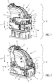
figure 1 depicts schematically in perspective a connection assembly comprising a connector and a counter connector, wherein these are not yet coupled together; -
figure 2 depicts schematically in perspective the connection assembly depicted infigure 1 , wherein these are coupled together; -
figures 3A and 3B depict schematically in perspective the connector depicted infigures 1 and 2 , respectively with the cable guide cover in a position in which it is engaged with the housing only via its rear portion, and said same connector, in the pre-coupling position, with the cable guide cover engaged with the housing likewise via its front portion, but with the slides in the initial position and not yet cooperating with the cable guide cover; -
figures 4A to 4C depict schematically in perspective the connector depicted infigures 1, 2 ,3A and 3B , with the slides respectively in the initial position, corresponding tofigure 3B , in an intermediate position and in their final position, -
figure 5 corresponds to a detail depicted in section infigure 4C ; and -
figure 6 corresponds to a detail of the system of engagement of the connector depicted in the preceding figures. - In the various figures, similar or identical elements bear the same references.
- The
connection assembly 100 depicted infigure 1 comprises aconnector 1 and acounter connector 2. In this figure, theconnector 1 and thecounter connector 2 are positioned with their coupling faces facing one another, although theconnector 1 and thecounter connector 2 are not coupled together. In order to be coupled and connected, theconnector 1 and thecounter connector 2 must be displaced one towards the other, in a direction of coupling A, shown vertically in the figures, and thecounter connector 2 must then be engaged, at least in part, in theconnector 1 by causing them to continue to be displaced in said direction of coupling A. - The
connector 1 comprises in particular ahousing 3, alever 4 for facilitating the connection, twoslides 5 likewise making a contribution to facilitating the connection and acable guide cover 6. Thehousing 3, thelever 4 for facilitating the connection, the twoslides 5 and thecable guide cover 6 are moulded in a plastic material. - The
connector 1 likewise comprises, albeit not illustrated here, female contacts or clips that are constituted by a metallic conductor. Similarly, thecounter connector 2 comprises male contacts or tongues (not depicted in the figures) that are constituted by a metallic conductor. - As may be appreciated in
figures 1 and 2 , thelever 4 is rotatably mounted on thecable guide cover 6, about an axis of rotation R, perpendicular to the direction of coupling A. Theslides 5 are mounted in translation, in a longitudinal direction L, simultaneously perpendicular to the directions of coupling A and rotation R, on thelongitudinal flanks 7 of thehousing 3. - In
figure 1 , thelever 4 is in the pre-coupling position in order to permit the coupling of theconnector 1 to thecounter connector 2, and theslides 6 are in the initial position. - In
figure 2 , theconnection assembly 100 is depicted with theconnector 1 and thecounter connector 2 coupled, that is to say attached mechanically to one another and connected electrically. When coupled to thecounter connector 2 in this way, theconnector 1 has itslever 4 in the locked position, and theslides 5 are in the final position. - The
lever 4 exhibits a generally "U"-shaped form with twobranches 7, each respectively constituting a lever arm. One extremity of each of said branches is articulated on one face of thecable guide cover 6 via the intermediary of anarticulation portion 8, whereas the other two extremities are connected via ahandle 9. - The
cable guide cover 6 is defined as having afront portion 11 that is opposite, relative to the longitudinal direction L, to arear portion 12 provided with anopening 13 for the passage of cables (not depicted in the figures) that are electrically connected to the contacts fitted in thehousing 3. The cables exiting via theopening 13 may be attached with one or a plurality of cable ties to acollar 14. Consequently, a considerable pulling force may possibly be applied to therear portion 12 of thecable guide cover 6, which pulling force could cause thecable guide cover 6, in particular at the level of itsfront portion 11, to become disassociated from thehousing 2. It is advantageous, therefore, to dispose robust and effective means in order to maintain thecable guide cover 6 on thehousing 3 and, indirectly, thelever 4 in engagement with theslides 5, as described below in a more detailed manner. - The
cable guide cover 6 comprises fixingfeet 15 that are integrally formed with the latter. They each extend respectively, in the direction of coupling A, from an edge of thecable guide cover 6 parallel to the longitudinal direction L. They are situated in the area of thefront portion 11 of thecable guide cover 6. The fixingfeet 15 comprise agroove 16 that is open towards the exterior of theconnector 1 and extend longitudinally parallel to the longitudinal direction L, when thecable guide cover 6 is fixed to thehousing 3. - As depicted in
figure 3A , thecable guide cover 6 comprises means of anchoring 17 situated in the area of therear portion 12 in proximity to the opening 13 (infigure 3A , thelever 4 not being depicted for greater clarity, although it is normally present in the course of this phase of assembling the connector 1). Said means of anchoring 17 are present, for example, in the form of a beam that is integrally formed with the rest of thecable guide cover 6. Said beam is engaged in a throat provided in theedge 18 extending therear face 19 of thehousing 3. For this purpose, thefront portion 11 of thecable guide cover 6 is raised in relation to thehousing 3, in such a way as to permit thearticulation portions 8 of thelever 4 to be inserted into a slot provided on the top of the slides 5 (seefigure 3B ). - Subsequently, as depicted in
figure 3B , thefront portion 11 of thecable guide cover 6 is lowered onto thehousing 3. Thecable guide cover 6 is maintained in this position with the help of ahook 20 engaging in anotch 21 produced on afoot 22 that is integrally formed with the housing 3 (seefigures 1 and 2 ). In the course of this operation, the fixingfeet 15 are each brought respectively into arecess 23 provided in the housing 3 (seeFigure 3A ). The fixingfeet 15 are then present in a zone of thehousing 3 that is covered by theslide 5, when the latter is in the final position (seefigures 4B and 4C , for example). In this position, therespective grooves 16 of the fixingfeet 15 are essentially present in the extension of asimilar groove 24 provided on each of the longitudinal lateral faces of thehousing 3, in proximity to an upper edge of the latter. As depicted in particular infigure 4A , anothergroove 25, parallel to the precedinggroove 24, is likewise provided on each of the lateral longitudinal faces of thehousing 3 in proximity to a lower edge of the latter. - Each
slide 5 is present in the form of a plate having means of restraining thecable guide cover 6. For example, said means of restraining thecable guide cover 6 comprise anupper rib 26 parallel to the longitudinal direction L. Eachslide 5 may likewise comprise alower rib 27 that is likewise parallel to the longitudinal direction L. Thelower ribs 27 and theupper ribs 26 are moulded together with eachslide 5. Eachslide 5 is then mounted on a longitudinal lateral face of thehousing 3 with itslower ribs 27 and itsupper ribs 26, each engaged respectively in agroove housing 3. Thegrooves recesses 23 for the fixingfeet 15, each slide being maintained accurately and in a robust manner for the major part of their length, on thehousing 3. - When the
lever 4 is pivoted from its pre-coupling position towards its locked position, eachslide 5 is brought by a system of gearing from its initial position depicted infigure 4A as far as its final position depicted infigure 4C , by passing through an intermediate position depicted infigure 4B . - In the initial position of the
slides 5, thecable guide cover 6 may be disassembled from thehousing 3 by releasing thehook 20 from thenotch 21 and by disengaging the beam from theedge 18. By contrast, in the final position of theslides 5, the latter cover the fixingfeet 15 and theirupper rib 26 is engaged in thegroove 16 of a fixingfoot 15. - As depicted in a more detailed manner in
figure 5 , each fixingfoot 15 comprises alower ramp 28 cooperating with aslide 5 when the latter is in the final position. Saidlower ramp 28 draws theslide 5 towards thecable guide cover 6. Conversely, each fixingfoot 15 comprises anupper ramp 29 cooperating with aslide 5 when the latter is in the final position. Saidramp 29 draws thecable guide cover 6 towards thehousing 3 when theslide 5 is in the final position. The lower ramps 26 and theupper ramps 29 assist the maintenance of theslides 5 by theribs grooves slides 5 in a better-adapted manner, in order to achieve a more accurate position of theslides 5 in relation to thecable guide cover 6 and to theteeth 30 of thelever 4. As depicted infigure 6 , this results in gear tracks (indicated as dashed lines), respectively on theteeth 30 of thelever 4 and on therack 31, which are combined in the course of the rotation of thelever 4. Given that thecable guide cover 6 is maintained securely and accurately on itsrear portion 12 thanks to the means of anchoring 17 that is maintained in the edge 18 (possibly inserted and wedged one in the other in the course of the positioning with a tilting movement of thecable guide cover 6, as illustrated byfigures 3A and 3B ), and that the fixingfeet 15 prevent thefront portion 12 of thecable guide cover 6 from deviating from theslides 5, the position of theteeth 30 on therack 31 may be defined and maintained in a precise manner. - It may also be noted in this figure that the rocking movement of the
cable guide cover 6 when returning thefront portion 11 of thecable guide cover 6 towards thehousing 3, while theslides 5 are in the initial position (as illustrated infigures 3A and 3B ), is advantageous in order to be able to bring theteeth 30 into engagement with therack 31 of eachslide 5. - It may also be noted in the figures that the driving
teeth 30 on eachslide 5 interact with arack 31 in the area of a portion of the connector situated towards therear face 19, in relation to the fixingfeet 15, which tends to be situated further towards the front. Thus, by reducing the free play in the area of the articulation of thecable guide cover 6, in the area of the means of anchoring 17, and by returning thecable guide cover 6 and eachslide 5 one towards the other, towards the front, thanks to the fixingfeet 15, it is possible to achieve even more accuracy in the relative position of theteeth 30 in relation to therack 31.
Claims (9)
- Connector comprising a housing (3), a lever (4) for facilitating the connection, a slide (5) for facilitating the connection, and a cable guide cover (6), in which- the lever (4) is rotatably mounted on the cable guide cover (6), about an axis of rotation (R), between a pre-coupling position and a locking position,- the slide (5) is movably mounted on the housing (3) and is driven, via the lever (4), in translation in a direction (L) that is perpendicular to the axis of rotation (R) of the lever (4), between an initial position corresponding to the pre-coupling position of the lever (4) and a final position corresponding to the locking position of the lever (4), characterized in that the slide (5) comprises means of restraining (26) the cable guide cover (6), which means are displaced together with the slide (5) and move into engagement with the cable guide cover (6) in the course of the rotation of the lever (4).
- Connector according to Claim 1, in which the cable guide cover (6) comprises a front portion (11) and a rear portion (12), the front portion (11) being provided with a fixing foot (15) that is disengaged from the means of restraining (26) the slide (5) when the slide (5) is in the initial position and cooperating with the means of restraining (26) the slide (5) when the slide (5) is in the final position, and the rear portion (12) being provided with a means of anchoring (17) the cable guide cover (6) on the housing (3).
- Connector according to Claim 2, the cable guide cover comprising an opening (13) situated in the rear portion (12) for the passage of at least one cable that is electrically connected to a contact mounted in the housing (3).
- Connector according to Claim 2 or 3, in which, in the course of positioning the cable guide cover (6) on the housing (3), the means of anchoring (17) are caused to engage with the housing (3), by raising the front portion (11) in relation to the housing (3), before returning the front portion (11) towards the housing (3) and placing the fixing foot (15) in a zone of the housing (3) that is covered by the slide (5), when the latter is in the final position.
- Connector according to Claim 4, in which the lever comprises teeth (30) for driving the slide (5), coming into engagement with a rack (31) of the slide (5) when the front portion (11) of the cable guide cover (6) is returned towards the housing (3) and when the slide (5) is in the initial position.
- Connector according to Claim 5, in which the teeth (30) for driving the slide (5) interact with the rack (31) of the slide (5) in the area of a portion of the connector situated towards the rear portion (12), in relation to the fixing foot (15).
- Connector according to one of the preceding claims 2 to 6, in which the fixing foot (15) comprises a ramp (29) cooperating with the slide (5), when the latter is in the final position, and drawing the cable guide cover (6) towards the housing (3), when the slide (5) is in the final position.
- Connector according to one of the preceding claims, in which the means of restraining (26) of the cable guide cover (6) comprise a rib that is integrally formed with the slide (5) and is engaged in a groove (16) of the cable guide cover (6), when the slide (5) is in the final position.
- Connection assembly comprising a connector according to one of the preceding claims and a counter connector (2), in which- the counter connector (2) may be coupled to the connector (1) when the lever (4) is in the pre-coupling position,- the connector (1) and the counter connector (2) are locked together in the locking position,- the slide (5) cooperates, in the course of its translation between its initial position and its final position, with the counter connector (2) in order to couple the counter connector (2) to the connector (1), and contributes, in the final position, to the maintenance of the cable guide cover (6), on the housing (3).
Applications Claiming Priority (1)
| Application Number | Priority Date | Filing Date | Title |
|---|---|---|---|
| FR1561197A FR3044173B1 (en) | 2015-11-20 | 2015-11-20 | CONNECTOR WITH CONNECTION ASSEMBLY SLIDE AND GUIDE-CABLE HOOD |
Publications (3)
| Publication Number | Publication Date |
|---|---|
| EP3171463A1 true EP3171463A1 (en) | 2017-05-24 |
| EP3171463B1 EP3171463B1 (en) | 2018-12-12 |
| EP3171463B8 EP3171463B8 (en) | 2019-02-27 |
Family
ID=55361672
Family Applications (1)
| Application Number | Title | Priority Date | Filing Date |
|---|---|---|---|
| EP16199668.1A Active EP3171463B8 (en) | 2015-11-20 | 2016-11-18 | Connector having a slide for facilitating connection and a cable guide cover |
Country Status (6)
| Country | Link |
|---|---|
| US (1) | US9768550B2 (en) |
| EP (1) | EP3171463B8 (en) |
| JP (1) | JP6827779B2 (en) |
| KR (1) | KR102649045B1 (en) |
| CN (1) | CN106785671B (en) |
| FR (1) | FR3044173B1 (en) |
Families Citing this family (5)
| Publication number | Priority date | Publication date | Assignee | Title |
|---|---|---|---|---|
| JP6618400B2 (en) * | 2016-03-25 | 2019-12-11 | 日本圧着端子製造株式会社 | Connector and electrical connection device |
| JP6755148B2 (en) * | 2016-08-30 | 2020-09-16 | タイコエレクトロニクスジャパン合同会社 | Lever type connector |
| JP6647739B2 (en) * | 2017-08-25 | 2020-02-14 | 矢崎総業株式会社 | Assembly structure of connector and connector cover |
| JP6879231B2 (en) * | 2018-03-06 | 2021-06-02 | 住友電装株式会社 | connector |
| DE102022134471B4 (en) * | 2022-12-22 | 2025-01-30 | Marelli Automotive Lighting Reutlingen (Germany) GmbH | Plug arrangement and socket arrangement for motor vehicle lighting devices |
Citations (6)
| Publication number | Priority date | Publication date | Assignee | Title |
|---|---|---|---|---|
| DE8700210U1 (en) * | 1987-01-05 | 1987-07-02 | Amp Inc., Harrisburg, Pa. | Connection arrangement with lifting racks |
| WO2002078126A2 (en) * | 2001-03-27 | 2002-10-03 | Fci | Electric connector |
| FR2853459A1 (en) * | 2003-04-07 | 2004-10-08 | Valeo Electronique Sys Liaison | Electrical connector for conductors, has body including slits on both sides of paths to receive plates, and cap, where each plate has projections provided against sides of paths |
| DE102006058680A1 (en) * | 2006-12-13 | 2008-06-19 | Kostal Kontakt Systeme Gmbh | Electrical connector |
| DE102011101205A1 (en) * | 2010-05-14 | 2012-02-23 | Sumitomo Wiring Systems, Ltd. | Interconnects |
| US9048579B2 (en) | 2012-11-13 | 2015-06-02 | Sumitomo Wiring Systems, Ltd. | Lever-type connector |
Family Cites Families (14)
| Publication number | Priority date | Publication date | Assignee | Title |
|---|---|---|---|---|
| EP0722203B1 (en) * | 1995-01-16 | 2003-04-16 | Molex Incorporated | Electrical connector assembly with improved camming system |
| EP0933836B1 (en) * | 1998-01-30 | 2005-03-23 | The Whitaker Corporation | Connector with coupling assist mechanism |
| DE19844693A1 (en) * | 1998-09-29 | 2000-03-30 | Delphi Automotive Systems Gmbh | Two part electrical connector |
| JP3492309B2 (en) * | 2000-11-02 | 2004-02-03 | エフシーアイジャパン株式会社 | connector |
| JP2002298982A (en) * | 2001-03-27 | 2002-10-11 | Molex Inc | Low insertion force connector |
| US7223130B2 (en) * | 2005-05-17 | 2007-05-29 | J.S.T. Corporation | Electrical connector |
| JP2006331991A (en) | 2005-05-30 | 2006-12-07 | Tyco Electronics Amp Kk | Lever-type connector |
| US7361036B2 (en) * | 2005-10-06 | 2008-04-22 | Fci Americas Technology, Inc. | Electrical connector with lever and latch |
| SG135994A1 (en) * | 2006-03-17 | 2007-10-29 | J S T Mfg Co Ltd | Electric connector |
| JP4382134B2 (en) * | 2008-03-28 | 2009-12-09 | タイコエレクトロニクスアンプ株式会社 | Lever type connector |
| JP4468465B2 (en) * | 2008-03-28 | 2010-05-26 | タイコエレクトロニクスジャパン合同会社 | Lever type connector |
| JP4405564B2 (en) * | 2008-04-21 | 2010-01-27 | タイコエレクトロニクスジャパン合同会社 | Lever type connector |
| WO2013135849A1 (en) * | 2012-03-16 | 2013-09-19 | Delphi Connection Systems Holding France | Electrical connector |
| JP5947678B2 (en) * | 2012-08-31 | 2016-07-06 | 矢崎総業株式会社 | Connector device |
-
2015
- 2015-11-20 FR FR1561197A patent/FR3044173B1/en not_active Expired - Fee Related
-
2016
- 2016-11-07 US US15/344,652 patent/US9768550B2/en active Active
- 2016-11-18 CN CN201611151882.7A patent/CN106785671B/en active Active
- 2016-11-18 KR KR1020160153775A patent/KR102649045B1/en active Active
- 2016-11-18 EP EP16199668.1A patent/EP3171463B8/en active Active
- 2016-11-18 JP JP2016224801A patent/JP6827779B2/en active Active
Patent Citations (6)
| Publication number | Priority date | Publication date | Assignee | Title |
|---|---|---|---|---|
| DE8700210U1 (en) * | 1987-01-05 | 1987-07-02 | Amp Inc., Harrisburg, Pa. | Connection arrangement with lifting racks |
| WO2002078126A2 (en) * | 2001-03-27 | 2002-10-03 | Fci | Electric connector |
| FR2853459A1 (en) * | 2003-04-07 | 2004-10-08 | Valeo Electronique Sys Liaison | Electrical connector for conductors, has body including slits on both sides of paths to receive plates, and cap, where each plate has projections provided against sides of paths |
| DE102006058680A1 (en) * | 2006-12-13 | 2008-06-19 | Kostal Kontakt Systeme Gmbh | Electrical connector |
| DE102011101205A1 (en) * | 2010-05-14 | 2012-02-23 | Sumitomo Wiring Systems, Ltd. | Interconnects |
| US9048579B2 (en) | 2012-11-13 | 2015-06-02 | Sumitomo Wiring Systems, Ltd. | Lever-type connector |
Also Published As
| Publication number | Publication date |
|---|---|
| JP6827779B2 (en) | 2021-02-10 |
| FR3044173B1 (en) | 2019-05-17 |
| EP3171463B8 (en) | 2019-02-27 |
| CN106785671B (en) | 2019-02-15 |
| US9768550B2 (en) | 2017-09-19 |
| KR20170059416A (en) | 2017-05-30 |
| KR102649045B1 (en) | 2024-03-20 |
| JP2017098248A (en) | 2017-06-01 |
| CN106785671A (en) | 2017-05-31 |
| FR3044173A1 (en) | 2017-05-26 |
| EP3171463B1 (en) | 2018-12-12 |
| US20170149174A1 (en) | 2017-05-25 |
Similar Documents
| Publication | Publication Date | Title |
|---|---|---|
| EP3171463B1 (en) | Connector having a slide for facilitating connection and a cable guide cover | |
| US10164373B1 (en) | Automatic engagement system for liquid or power connections | |
| CN112152018B (en) | Electrical connector set, electrical connector and method for connecting and disconnecting electrical connector set and electrical connector set with butting connector | |
| US10833452B2 (en) | Connector with a lever for assistance with connection and method for packaging a connector of this type | |
| CN108736250B (en) | electrical connector with lever | |
| EP2822108B1 (en) | Bus bar adapter and assembly with bus bar adapter and bus bar | |
| US20110116233A1 (en) | Fan Tray that is Installable and Removable from the Front and Back of a Network Element Chassis | |
| CN110176682B (en) | Connector assembly and plug thereof | |
| US9088100B2 (en) | Connector with secure engagement | |
| JP2012160445A5 (en) | ||
| JP2000148214A (en) | Programmable logic controller and programmable logic controller module | |
| EP2710684B1 (en) | Electrical connector assembly, and connector for such assembly | |
| JP2016537778A (en) | Dual moving mating auxiliary connector | |
| KR20190114958A (en) | Door locks for appliances, especially ovens | |
| EP3163687A1 (en) | Connector having locking of the lever for facilitating the connection | |
| US6265678B1 (en) | Circuit breaker movement system with over-travel protection | |
| US9291184B2 (en) | Electrical connecting device | |
| JP2024019072A (en) | Housing assemblies for electrical connectors with mating aids, as well as electrical connectors and connector assemblies | |
| US20220196194A1 (en) | Coupling device | |
| EP3676917A1 (en) | Plug connection for automated coupling of at least two electrical conductors | |
| KR101632704B1 (en) | Connector assembly | |
| JP7758795B2 (en) | Connector housing assemblies, connectors, and connection assemblies | |
| JP2019106373A (en) | Electrical distribution assembly | |
| KR100955053B1 (en) | Connector mating / unplugging device | |
| CN111063575B (en) | Switch cabinet with cabinet door and grounding switch interlocking device |
Legal Events
| Date | Code | Title | Description |
|---|---|---|---|
| PUAI | Public reference made under article 153(3) epc to a published international application that has entered the european phase |
Free format text: ORIGINAL CODE: 0009012 |
|
| STAA | Information on the status of an ep patent application or granted ep patent |
Free format text: STATUS: THE APPLICATION HAS BEEN PUBLISHED |
|
| AK | Designated contracting states |
Kind code of ref document: A1 Designated state(s): AL AT BE BG CH CY CZ DE DK EE ES FI FR GB GR HR HU IE IS IT LI LT LU LV MC MK MT NL NO PL PT RO RS SE SI SK SM TR |
|
| AX | Request for extension of the european patent |
Extension state: BA ME |
|
| STAA | Information on the status of an ep patent application or granted ep patent |
Free format text: STATUS: REQUEST FOR EXAMINATION WAS MADE |
|
| 17P | Request for examination filed |
Effective date: 20171124 |
|
| RBV | Designated contracting states (corrected) |
Designated state(s): AL AT BE BG CH CY CZ DE DK EE ES FI FR GB GR HR HU IE IS IT LI LT LU LV MC MK MT NL NO PL PT RO RS SE SI SK SM TR |
|
| GRAP | Despatch of communication of intention to grant a patent |
Free format text: ORIGINAL CODE: EPIDOSNIGR1 |
|
| STAA | Information on the status of an ep patent application or granted ep patent |
Free format text: STATUS: GRANT OF PATENT IS INTENDED |
|
| RIC1 | Information provided on ipc code assigned before grant |
Ipc: H01R 13/506 20060101ALN20180612BHEP Ipc: H01R 13/56 20060101ALI20180612BHEP Ipc: H01R 13/629 20060101AFI20180612BHEP |
|
| INTG | Intention to grant announced |
Effective date: 20180629 |
|
| GRAS | Grant fee paid |
Free format text: ORIGINAL CODE: EPIDOSNIGR3 |
|
| GRAA | (expected) grant |
Free format text: ORIGINAL CODE: 0009210 |
|
| STAA | Information on the status of an ep patent application or granted ep patent |
Free format text: STATUS: THE PATENT HAS BEEN GRANTED |
|
| AK | Designated contracting states |
Kind code of ref document: B1 Designated state(s): AL AT BE BG CH CY CZ DE DK EE ES FI FR GB GR HR HU IE IS IT LI LT LU LV MC MK MT NL NO PL PT RO RS SE SI SK SM TR |
|
| REG | Reference to a national code |
Ref country code: GB Ref legal event code: FG4D |
|
| REG | Reference to a national code |
Ref country code: CH Ref legal event code: EP |
|
| REG | Reference to a national code |
Ref country code: AT Ref legal event code: REF Ref document number: 1077222 Country of ref document: AT Kind code of ref document: T Effective date: 20181215 |
|
| RAP2 | Party data changed (patent owner data changed or rights of a patent transferred) |
Owner name: APTIV TECHNOLOGIES LIMITED |
|
| REG | Reference to a national code |
Ref country code: DE Ref legal event code: R096 Ref document number: 602016008117 Country of ref document: DE |
|
| REG | Reference to a national code |
Ref country code: IE Ref legal event code: FG4D |
|
| REG | Reference to a national code |
Ref country code: CH Ref legal event code: PK Free format text: BERICHTIGUNG B8 |
|
| REG | Reference to a national code |
Ref country code: NL Ref legal event code: MP Effective date: 20181212 |
|
| REG | Reference to a national code |
Ref country code: LT Ref legal event code: MG4D |
|
| PG25 | Lapsed in a contracting state [announced via postgrant information from national office to epo] |
Ref country code: ES Free format text: LAPSE BECAUSE OF FAILURE TO SUBMIT A TRANSLATION OF THE DESCRIPTION OR TO PAY THE FEE WITHIN THE PRESCRIBED TIME-LIMIT Effective date: 20181212 Ref country code: NO Free format text: LAPSE BECAUSE OF FAILURE TO SUBMIT A TRANSLATION OF THE DESCRIPTION OR TO PAY THE FEE WITHIN THE PRESCRIBED TIME-LIMIT Effective date: 20190312 Ref country code: LT Free format text: LAPSE BECAUSE OF FAILURE TO SUBMIT A TRANSLATION OF THE DESCRIPTION OR TO PAY THE FEE WITHIN THE PRESCRIBED TIME-LIMIT Effective date: 20181212 Ref country code: HR Free format text: LAPSE BECAUSE OF FAILURE TO SUBMIT A TRANSLATION OF THE DESCRIPTION OR TO PAY THE FEE WITHIN THE PRESCRIBED TIME-LIMIT Effective date: 20181212 Ref country code: BG Free format text: LAPSE BECAUSE OF FAILURE TO SUBMIT A TRANSLATION OF THE DESCRIPTION OR TO PAY THE FEE WITHIN THE PRESCRIBED TIME-LIMIT Effective date: 20190312 Ref country code: FI Free format text: LAPSE BECAUSE OF FAILURE TO SUBMIT A TRANSLATION OF THE DESCRIPTION OR TO PAY THE FEE WITHIN THE PRESCRIBED TIME-LIMIT Effective date: 20181212 Ref country code: LV Free format text: LAPSE BECAUSE OF FAILURE TO SUBMIT A TRANSLATION OF THE DESCRIPTION OR TO PAY THE FEE WITHIN THE PRESCRIBED TIME-LIMIT Effective date: 20181212 |
|
| REG | Reference to a national code |
Ref country code: AT Ref legal event code: MK05 Ref document number: 1077222 Country of ref document: AT Kind code of ref document: T Effective date: 20181212 |
|
| PG25 | Lapsed in a contracting state [announced via postgrant information from national office to epo] |
Ref country code: RS Free format text: LAPSE BECAUSE OF FAILURE TO SUBMIT A TRANSLATION OF THE DESCRIPTION OR TO PAY THE FEE WITHIN THE PRESCRIBED TIME-LIMIT Effective date: 20181212 Ref country code: SE Free format text: LAPSE BECAUSE OF FAILURE TO SUBMIT A TRANSLATION OF THE DESCRIPTION OR TO PAY THE FEE WITHIN THE PRESCRIBED TIME-LIMIT Effective date: 20181212 Ref country code: AL Free format text: LAPSE BECAUSE OF FAILURE TO SUBMIT A TRANSLATION OF THE DESCRIPTION OR TO PAY THE FEE WITHIN THE PRESCRIBED TIME-LIMIT Effective date: 20181212 Ref country code: GR Free format text: LAPSE BECAUSE OF FAILURE TO SUBMIT A TRANSLATION OF THE DESCRIPTION OR TO PAY THE FEE WITHIN THE PRESCRIBED TIME-LIMIT Effective date: 20190313 |
|
| PG25 | Lapsed in a contracting state [announced via postgrant information from national office to epo] |
Ref country code: NL Free format text: LAPSE BECAUSE OF FAILURE TO SUBMIT A TRANSLATION OF THE DESCRIPTION OR TO PAY THE FEE WITHIN THE PRESCRIBED TIME-LIMIT Effective date: 20181212 |
|
| PG25 | Lapsed in a contracting state [announced via postgrant information from national office to epo] |
Ref country code: PT Free format text: LAPSE BECAUSE OF FAILURE TO SUBMIT A TRANSLATION OF THE DESCRIPTION OR TO PAY THE FEE WITHIN THE PRESCRIBED TIME-LIMIT Effective date: 20190412 Ref country code: PL Free format text: LAPSE BECAUSE OF FAILURE TO SUBMIT A TRANSLATION OF THE DESCRIPTION OR TO PAY THE FEE WITHIN THE PRESCRIBED TIME-LIMIT Effective date: 20181212 Ref country code: IT Free format text: LAPSE BECAUSE OF FAILURE TO SUBMIT A TRANSLATION OF THE DESCRIPTION OR TO PAY THE FEE WITHIN THE PRESCRIBED TIME-LIMIT Effective date: 20181212 Ref country code: CZ Free format text: LAPSE BECAUSE OF FAILURE TO SUBMIT A TRANSLATION OF THE DESCRIPTION OR TO PAY THE FEE WITHIN THE PRESCRIBED TIME-LIMIT Effective date: 20181212 |
|
| PG25 | Lapsed in a contracting state [announced via postgrant information from national office to epo] |
Ref country code: SM Free format text: LAPSE BECAUSE OF FAILURE TO SUBMIT A TRANSLATION OF THE DESCRIPTION OR TO PAY THE FEE WITHIN THE PRESCRIBED TIME-LIMIT Effective date: 20181212 Ref country code: EE Free format text: LAPSE BECAUSE OF FAILURE TO SUBMIT A TRANSLATION OF THE DESCRIPTION OR TO PAY THE FEE WITHIN THE PRESCRIBED TIME-LIMIT Effective date: 20181212 Ref country code: IS Free format text: LAPSE BECAUSE OF FAILURE TO SUBMIT A TRANSLATION OF THE DESCRIPTION OR TO PAY THE FEE WITHIN THE PRESCRIBED TIME-LIMIT Effective date: 20190412 Ref country code: RO Free format text: LAPSE BECAUSE OF FAILURE TO SUBMIT A TRANSLATION OF THE DESCRIPTION OR TO PAY THE FEE WITHIN THE PRESCRIBED TIME-LIMIT Effective date: 20181212 Ref country code: SK Free format text: LAPSE BECAUSE OF FAILURE TO SUBMIT A TRANSLATION OF THE DESCRIPTION OR TO PAY THE FEE WITHIN THE PRESCRIBED TIME-LIMIT Effective date: 20181212 |
|
| REG | Reference to a national code |
Ref country code: DE Ref legal event code: R097 Ref document number: 602016008117 Country of ref document: DE |
|
| PLBE | No opposition filed within time limit |
Free format text: ORIGINAL CODE: 0009261 |
|
| STAA | Information on the status of an ep patent application or granted ep patent |
Free format text: STATUS: NO OPPOSITION FILED WITHIN TIME LIMIT |
|
| PG25 | Lapsed in a contracting state [announced via postgrant information from national office to epo] |
Ref country code: AT Free format text: LAPSE BECAUSE OF FAILURE TO SUBMIT A TRANSLATION OF THE DESCRIPTION OR TO PAY THE FEE WITHIN THE PRESCRIBED TIME-LIMIT Effective date: 20181212 Ref country code: DK Free format text: LAPSE BECAUSE OF FAILURE TO SUBMIT A TRANSLATION OF THE DESCRIPTION OR TO PAY THE FEE WITHIN THE PRESCRIBED TIME-LIMIT Effective date: 20181212 Ref country code: SI Free format text: LAPSE BECAUSE OF FAILURE TO SUBMIT A TRANSLATION OF THE DESCRIPTION OR TO PAY THE FEE WITHIN THE PRESCRIBED TIME-LIMIT Effective date: 20181212 |
|
| 26N | No opposition filed |
Effective date: 20190913 |
|
| PG25 | Lapsed in a contracting state [announced via postgrant information from national office to epo] |
Ref country code: TR Free format text: LAPSE BECAUSE OF FAILURE TO SUBMIT A TRANSLATION OF THE DESCRIPTION OR TO PAY THE FEE WITHIN THE PRESCRIBED TIME-LIMIT Effective date: 20181212 |
|
| REG | Reference to a national code |
Ref country code: CH Ref legal event code: PL |
|
| PG25 | Lapsed in a contracting state [announced via postgrant information from national office to epo] |
Ref country code: MC Free format text: LAPSE BECAUSE OF FAILURE TO SUBMIT A TRANSLATION OF THE DESCRIPTION OR TO PAY THE FEE WITHIN THE PRESCRIBED TIME-LIMIT Effective date: 20181212 Ref country code: LU Free format text: LAPSE BECAUSE OF NON-PAYMENT OF DUE FEES Effective date: 20191118 Ref country code: CH Free format text: LAPSE BECAUSE OF NON-PAYMENT OF DUE FEES Effective date: 20191130 Ref country code: LI Free format text: LAPSE BECAUSE OF NON-PAYMENT OF DUE FEES Effective date: 20191130 |
|
| REG | Reference to a national code |
Ref country code: BE Ref legal event code: MM Effective date: 20191130 |
|
| PG25 | Lapsed in a contracting state [announced via postgrant information from national office to epo] |
Ref country code: IE Free format text: LAPSE BECAUSE OF NON-PAYMENT OF DUE FEES Effective date: 20191118 |
|
| PG25 | Lapsed in a contracting state [announced via postgrant information from national office to epo] |
Ref country code: BE Free format text: LAPSE BECAUSE OF NON-PAYMENT OF DUE FEES Effective date: 20191130 |
|
| PG25 | Lapsed in a contracting state [announced via postgrant information from national office to epo] |
Ref country code: CY Free format text: LAPSE BECAUSE OF FAILURE TO SUBMIT A TRANSLATION OF THE DESCRIPTION OR TO PAY THE FEE WITHIN THE PRESCRIBED TIME-LIMIT Effective date: 20181212 |
|
| PG25 | Lapsed in a contracting state [announced via postgrant information from national office to epo] |
Ref country code: HU Free format text: LAPSE BECAUSE OF FAILURE TO SUBMIT A TRANSLATION OF THE DESCRIPTION OR TO PAY THE FEE WITHIN THE PRESCRIBED TIME-LIMIT; INVALID AB INITIO Effective date: 20161118 Ref country code: MT Free format text: LAPSE BECAUSE OF FAILURE TO SUBMIT A TRANSLATION OF THE DESCRIPTION OR TO PAY THE FEE WITHIN THE PRESCRIBED TIME-LIMIT Effective date: 20181212 |
|
| PG25 | Lapsed in a contracting state [announced via postgrant information from national office to epo] |
Ref country code: MK Free format text: LAPSE BECAUSE OF FAILURE TO SUBMIT A TRANSLATION OF THE DESCRIPTION OR TO PAY THE FEE WITHIN THE PRESCRIBED TIME-LIMIT Effective date: 20181212 |
|
| P01 | Opt-out of the competence of the unified patent court (upc) registered |
Effective date: 20230425 |
|
| REG | Reference to a national code |
Ref country code: DE Ref legal event code: R081 Ref document number: 602016008117 Country of ref document: DE Owner name: APTIV TECHNOLOGIES AG, CH Free format text: FORMER OWNER: DELPHI INTERNATIONAL OPERATIONS LUXEMBOURG S.A R.L., BASCHARAGE, LU |
|
| PGFP | Annual fee paid to national office [announced via postgrant information from national office to epo] |
Ref country code: DE Payment date: 20251010 Year of fee payment: 10 |
|
| PGFP | Annual fee paid to national office [announced via postgrant information from national office to epo] |
Ref country code: GB Payment date: 20251107 Year of fee payment: 10 |
|
| PGFP | Annual fee paid to national office [announced via postgrant information from national office to epo] |
Ref country code: FR Payment date: 20251112 Year of fee payment: 10 |