EP3171460A1 - Connector housing assembly and electrical connector assembly - Google Patents
Connector housing assembly and electrical connector assembly Download PDFInfo
- Publication number
- EP3171460A1 EP3171460A1 EP16200273.7A EP16200273A EP3171460A1 EP 3171460 A1 EP3171460 A1 EP 3171460A1 EP 16200273 A EP16200273 A EP 16200273A EP 3171460 A1 EP3171460 A1 EP 3171460A1
- Authority
- EP
- European Patent Office
- Prior art keywords
- housing
- connector
- insert
- cable
- connector housing
- Prior art date
- Legal status (The legal status is an assumption and is not a legal conclusion. Google has not performed a legal analysis and makes no representation as to the accuracy of the status listed.)
- Granted
Links
Images




Classifications
-
- H—ELECTRICITY
- H01—ELECTRIC ELEMENTS
- H01R—ELECTRICALLY-CONDUCTIVE CONNECTIONS; STRUCTURAL ASSOCIATIONS OF A PLURALITY OF MUTUALLY-INSULATED ELECTRICAL CONNECTING ELEMENTS; COUPLING DEVICES; CURRENT COLLECTORS
- H01R24/00—Two-part coupling devices, or either of their cooperating parts, characterised by their overall structure
- H01R24/76—Two-part coupling devices, or either of their cooperating parts, characterised by their overall structure with sockets, clips or analogous contacts and secured to apparatus or structure, e.g. to a wall
- H01R24/78—Two-part coupling devices, or either of their cooperating parts, characterised by their overall structure with sockets, clips or analogous contacts and secured to apparatus or structure, e.g. to a wall with additional earth or shield contacts
-
- H—ELECTRICITY
- H01—ELECTRIC ELEMENTS
- H01R—ELECTRICALLY-CONDUCTIVE CONNECTIONS; STRUCTURAL ASSOCIATIONS OF A PLURALITY OF MUTUALLY-INSULATED ELECTRICAL CONNECTING ELEMENTS; COUPLING DEVICES; CURRENT COLLECTORS
- H01R35/00—Flexible or turnable line connectors, i.e. the rotation angle being limited
-
- H—ELECTRICITY
- H01—ELECTRIC ELEMENTS
- H01R—ELECTRICALLY-CONDUCTIVE CONNECTIONS; STRUCTURAL ASSOCIATIONS OF A PLURALITY OF MUTUALLY-INSULATED ELECTRICAL CONNECTING ELEMENTS; COUPLING DEVICES; CURRENT COLLECTORS
- H01R13/00—Details of coupling devices of the kinds covered by groups H01R12/70 or H01R24/00 - H01R33/00
- H01R13/648—Protective earth or shield arrangements on coupling devices, e.g. anti-static shielding
- H01R13/658—High frequency shielding arrangements, e.g. against EMI [Electro-Magnetic Interference] or EMP [Electro-Magnetic Pulse]
- H01R13/6581—Shield structure
- H01R13/6582—Shield structure with resilient means for engaging mating connector
-
- H—ELECTRICITY
- H01—ELECTRIC ELEMENTS
- H01R—ELECTRICALLY-CONDUCTIVE CONNECTIONS; STRUCTURAL ASSOCIATIONS OF A PLURALITY OF MUTUALLY-INSULATED ELECTRICAL CONNECTING ELEMENTS; COUPLING DEVICES; CURRENT COLLECTORS
- H01R13/00—Details of coupling devices of the kinds covered by groups H01R12/70 or H01R24/00 - H01R33/00
- H01R13/46—Bases; Cases
-
- H—ELECTRICITY
- H01—ELECTRIC ELEMENTS
- H01R—ELECTRICALLY-CONDUCTIVE CONNECTIONS; STRUCTURAL ASSOCIATIONS OF A PLURALITY OF MUTUALLY-INSULATED ELECTRICAL CONNECTING ELEMENTS; COUPLING DEVICES; CURRENT COLLECTORS
- H01R13/00—Details of coupling devices of the kinds covered by groups H01R12/70 or H01R24/00 - H01R33/00
- H01R13/46—Bases; Cases
- H01R13/502—Bases; Cases composed of different pieces
-
- H—ELECTRICITY
- H01—ELECTRIC ELEMENTS
- H01R—ELECTRICALLY-CONDUCTIVE CONNECTIONS; STRUCTURAL ASSOCIATIONS OF A PLURALITY OF MUTUALLY-INSULATED ELECTRICAL CONNECTING ELEMENTS; COUPLING DEVICES; CURRENT COLLECTORS
- H01R13/00—Details of coupling devices of the kinds covered by groups H01R12/70 or H01R24/00 - H01R33/00
- H01R13/46—Bases; Cases
- H01R13/516—Means for holding or embracing insulating body, e.g. casing, hoods
-
- H—ELECTRICITY
- H01—ELECTRIC ELEMENTS
- H01R—ELECTRICALLY-CONDUCTIVE CONNECTIONS; STRUCTURAL ASSOCIATIONS OF A PLURALITY OF MUTUALLY-INSULATED ELECTRICAL CONNECTING ELEMENTS; COUPLING DEVICES; CURRENT COLLECTORS
- H01R13/00—Details of coupling devices of the kinds covered by groups H01R12/70 or H01R24/00 - H01R33/00
- H01R13/46—Bases; Cases
- H01R13/52—Dustproof, splashproof, drip-proof, waterproof, or flameproof cases
- H01R13/5202—Sealing means between parts of housing or between housing part and a wall, e.g. sealing rings
-
- H—ELECTRICITY
- H01—ELECTRIC ELEMENTS
- H01R—ELECTRICALLY-CONDUCTIVE CONNECTIONS; STRUCTURAL ASSOCIATIONS OF A PLURALITY OF MUTUALLY-INSULATED ELECTRICAL CONNECTING ELEMENTS; COUPLING DEVICES; CURRENT COLLECTORS
- H01R13/00—Details of coupling devices of the kinds covered by groups H01R12/70 or H01R24/00 - H01R33/00
- H01R13/46—Bases; Cases
- H01R13/52—Dustproof, splashproof, drip-proof, waterproof, or flameproof cases
- H01R13/5205—Sealing means between cable and housing, e.g. grommet
- H01R13/5208—Sealing means between cable and housing, e.g. grommet having at least two cable receiving openings
-
- H—ELECTRICITY
- H01—ELECTRIC ELEMENTS
- H01R—ELECTRICALLY-CONDUCTIVE CONNECTIONS; STRUCTURAL ASSOCIATIONS OF A PLURALITY OF MUTUALLY-INSULATED ELECTRICAL CONNECTING ELEMENTS; COUPLING DEVICES; CURRENT COLLECTORS
- H01R13/00—Details of coupling devices of the kinds covered by groups H01R12/70 or H01R24/00 - H01R33/00
- H01R13/58—Means for relieving strain on wire connection, e.g. cord grip, for avoiding loosening of connections between wires and terminals within a coupling device terminating a cable
- H01R13/5841—Means for relieving strain on wire connection, e.g. cord grip, for avoiding loosening of connections between wires and terminals within a coupling device terminating a cable allowing different orientations of the cable with respect to the coupling direction
-
- H—ELECTRICITY
- H01—ELECTRIC ELEMENTS
- H01R—ELECTRICALLY-CONDUCTIVE CONNECTIONS; STRUCTURAL ASSOCIATIONS OF A PLURALITY OF MUTUALLY-INSULATED ELECTRICAL CONNECTING ELEMENTS; COUPLING DEVICES; CURRENT COLLECTORS
- H01R13/00—Details of coupling devices of the kinds covered by groups H01R12/70 or H01R24/00 - H01R33/00
- H01R13/62—Means for facilitating engagement or disengagement of coupling parts or for holding them in engagement
- H01R13/627—Snap or like fastening
- H01R13/6271—Latching means integral with the housing
- H01R13/6272—Latching means integral with the housing comprising a single latching arm
-
- H—ELECTRICITY
- H01—ELECTRIC ELEMENTS
- H01R—ELECTRICALLY-CONDUCTIVE CONNECTIONS; STRUCTURAL ASSOCIATIONS OF A PLURALITY OF MUTUALLY-INSULATED ELECTRICAL CONNECTING ELEMENTS; COUPLING DEVICES; CURRENT COLLECTORS
- H01R13/00—Details of coupling devices of the kinds covered by groups H01R12/70 or H01R24/00 - H01R33/00
- H01R13/62—Means for facilitating engagement or disengagement of coupling parts or for holding them in engagement
- H01R13/629—Additional means for facilitating engagement or disengagement of coupling parts, e.g. aligning or guiding means, levers, gas pressure electrical locking indicators, manufacturing tolerances
- H01R13/631—Additional means for facilitating engagement or disengagement of coupling parts, e.g. aligning or guiding means, levers, gas pressure electrical locking indicators, manufacturing tolerances for engagement only
-
- H—ELECTRICITY
- H01—ELECTRIC ELEMENTS
- H01R—ELECTRICALLY-CONDUCTIVE CONNECTIONS; STRUCTURAL ASSOCIATIONS OF A PLURALITY OF MUTUALLY-INSULATED ELECTRICAL CONNECTING ELEMENTS; COUPLING DEVICES; CURRENT COLLECTORS
- H01R13/00—Details of coupling devices of the kinds covered by groups H01R12/70 or H01R24/00 - H01R33/00
- H01R13/648—Protective earth or shield arrangements on coupling devices, e.g. anti-static shielding
- H01R13/658—High frequency shielding arrangements, e.g. against EMI [Electro-Magnetic Interference] or EMP [Electro-Magnetic Pulse]
- H01R13/6581—Shield structure
-
- H—ELECTRICITY
- H01—ELECTRIC ELEMENTS
- H01R—ELECTRICALLY-CONDUCTIVE CONNECTIONS; STRUCTURAL ASSOCIATIONS OF A PLURALITY OF MUTUALLY-INSULATED ELECTRICAL CONNECTING ELEMENTS; COUPLING DEVICES; CURRENT COLLECTORS
- H01R13/00—Details of coupling devices of the kinds covered by groups H01R12/70 or H01R24/00 - H01R33/00
- H01R13/73—Means for mounting coupling parts to apparatus or structures, e.g. to a wall
- H01R13/74—Means for mounting coupling parts in openings of a panel
-
- H—ELECTRICITY
- H01—ELECTRIC ELEMENTS
- H01R—ELECTRICALLY-CONDUCTIVE CONNECTIONS; STRUCTURAL ASSOCIATIONS OF A PLURALITY OF MUTUALLY-INSULATED ELECTRICAL CONNECTING ELEMENTS; COUPLING DEVICES; CURRENT COLLECTORS
- H01R13/00—Details of coupling devices of the kinds covered by groups H01R12/70 or H01R24/00 - H01R33/00
- H01R13/46—Bases; Cases
- H01R13/502—Bases; Cases composed of different pieces
- H01R13/506—Bases; Cases composed of different pieces assembled by snap action of the parts
-
- H—ELECTRICITY
- H01—ELECTRIC ELEMENTS
- H01R—ELECTRICALLY-CONDUCTIVE CONNECTIONS; STRUCTURAL ASSOCIATIONS OF A PLURALITY OF MUTUALLY-INSULATED ELECTRICAL CONNECTING ELEMENTS; COUPLING DEVICES; CURRENT COLLECTORS
- H01R13/00—Details of coupling devices of the kinds covered by groups H01R12/70 or H01R24/00 - H01R33/00
- H01R13/46—Bases; Cases
- H01R13/52—Dustproof, splashproof, drip-proof, waterproof, or flameproof cases
- H01R13/5219—Sealing means between coupling parts, e.g. interfacial seal
-
- H—ELECTRICITY
- H01—ELECTRIC ELEMENTS
- H01R—ELECTRICALLY-CONDUCTIVE CONNECTIONS; STRUCTURAL ASSOCIATIONS OF A PLURALITY OF MUTUALLY-INSULATED ELECTRICAL CONNECTING ELEMENTS; COUPLING DEVICES; CURRENT COLLECTORS
- H01R13/00—Details of coupling devices of the kinds covered by groups H01R12/70 or H01R24/00 - H01R33/00
- H01R13/46—Bases; Cases
- H01R13/52—Dustproof, splashproof, drip-proof, waterproof, or flameproof cases
- H01R13/5219—Sealing means between coupling parts, e.g. interfacial seal
- H01R13/5221—Sealing means between coupling parts, e.g. interfacial seal having cable sealing means
-
- H—ELECTRICITY
- H01—ELECTRIC ELEMENTS
- H01R—ELECTRICALLY-CONDUCTIVE CONNECTIONS; STRUCTURAL ASSOCIATIONS OF A PLURALITY OF MUTUALLY-INSULATED ELECTRICAL CONNECTING ELEMENTS; COUPLING DEVICES; CURRENT COLLECTORS
- H01R2103/00—Two poles
-
- H—ELECTRICITY
- H01—ELECTRIC ELEMENTS
- H01R—ELECTRICALLY-CONDUCTIVE CONNECTIONS; STRUCTURAL ASSOCIATIONS OF A PLURALITY OF MUTUALLY-INSULATED ELECTRICAL CONNECTING ELEMENTS; COUPLING DEVICES; CURRENT COLLECTORS
- H01R24/00—Two-part coupling devices, or either of their cooperating parts, characterised by their overall structure
- H01R24/20—Coupling parts carrying sockets, clips or analogous contacts and secured only to wire or cable
-
- H—ELECTRICITY
- H01—ELECTRIC ELEMENTS
- H01R—ELECTRICALLY-CONDUCTIVE CONNECTIONS; STRUCTURAL ASSOCIATIONS OF A PLURALITY OF MUTUALLY-INSULATED ELECTRICAL CONNECTING ELEMENTS; COUPLING DEVICES; CURRENT COLLECTORS
- H01R24/00—Two-part coupling devices, or either of their cooperating parts, characterised by their overall structure
- H01R24/66—Two-part coupling devices, or either of their cooperating parts, characterised by their overall structure with pins, blades or analogous contacts and secured to apparatus or structure, e.g. to a wall
Definitions
- the invention relates to a connector housing assembly for an electrical connector, comprising a connector housing and a mating connector housing, which are configured to be connected to each other in a first position at a respective connecting section by being moved along a plug direction towards each other, the connector housing further comprising a cable-side receptacle for a cable, the receptacle opening in a cable direction and the mating connector housing comprising a contact-side receptacle for a cable and/or at least one contact element, the receptacle opening in a contact direction, both receptacles being located at an end opposite the connecting section in the respective connector housing.
- the invention furthermore relates to an electrical connector assembly comprising an electrical connector with a connector housing and an electrical conductor within the connector housing, an electrical mating connector with a mating connector housing and a mating electric conductor.
- the connectors are configured to be connected to each other in a first position at a respective connecting section by being moved along a plug direction towards each other, the connector housing further comprising a cable-side receptacle opening in a cable direction and receiving the electric conductor, and the mating connector housing comprising a contact-side receptacle opening in a contact direction and receiving the mating electric conductor, both receptacles being located at an and opposite the connecting section in the respective connector housing.
- Connector housing assemblies are known from the prior art. If they are configured for an electrical angle connector, they are constructed for being plugged in a first position and are not adapted to be utilized in a configuration allowing a different plug angle. In order to obtain a different plug angle, another connector housing assembly or at least another additional connector housing has to be applied.
- contact pins may not be inserted into the connector housing from the cable-side. Therefore, contact pins of the prior art either require several parts or demand being molded into the connector housing. A contact pin comprising several parts has a higher contact resistance resulting in a decrease of the power that can be transmitted by such an angle plug.
- an additional 90° plug needs to be incorporated into the system.
- the additional element also increases the contact resistance.
- the object of the invention is therefore to provide a connector housing assembly which may be versatilely applied in different plug positions without demanding for additional elements.
- the object of the invention is to provide an electrical connector assembly that can be adapted to have an angle between contact pins and/or a cable of a mating connector and the cable of the electrical connector of either 90° or 180° without the need for additional elements and without increasing the contact resistance of the electrical connector assembly.
- the connector housing assembly comprises a connector housing and a mating connector housing which are adapted to be plugged together in a second position, wherein in the second position one of the connector housing or the mating connector housing is rotated about the plug direction compared to the first position.
- the cable direction and the contact direction are substantially perpendicular to each other, whereas in the second position, the cable direction and the contact direction are substantially parallel to each other.
- the inventive electrical connector assembly solves the above-mentioned problem by providing a connector housing and the mating connector housing which are adapted to be plugged together in a second position, wherein in the second position one of the connector housing or the mating connector housing is rotated about the plug direction compared to the first position and in that, in the first position, the electric conductor received in the cable-side receptacle and the mating electric conductor received in the contact-side receptacle are substantially perpendicular to each other, whereas in the second position, they are substantially parallel to each other.
- the cable direction and the plug direction are at an angle of at least approximately 45° to each other and/or the contact direction and the plug direction are at an angle of at least approximately 45° to each other.
- both housings yield an angle of at least approximately 135° between their receptacles.
- the two equal angular changes in direction of at least approximately 45° may add up to a change in direction of at least approximately 90°.
- the angular change in direction introduced by the connector housing may compensate for the angular change in direction introduced by the mating connector housing as the angular change in direction is opposite for both housings.
- plug positions may be obtained, wherein the obtained cable direction and contact direction may be at an angle different than 90° and 180°.
- the angles between the cable direction and the contact direction are not equal as in solutions of the prior art.
- a connector insert and/or a mating connector insert which is/are adapted to be inserted into the according housing against the cable direction and/or the contact direction respectively, the connector insert comprising a cable-side portion and a connector-site portion, the mating connector insert comprising a contact-side portion and a connector-side portion, the connector insert and/or the mating connector insert extending, if mounted to the according housing, from the connecting section to the receptacle being located at an end opposite the connecting section in the respective housing.
- Both housings may be embodied as one part.
- the connector insert is, for instance, inserted into the connector housing from either the cable-side or from the connection-side which is defined as the side towards which the receptacle located at the connecting section opens.
- the mating connector insert may similarly be inserted into the mating connector housing, that is either from the connection-side or from the cable-side.
- the connector housing and/or the mating connector housing may comprise two parts, wherein during assembly of the connector insert and/or the mating connector insert, said insert is inserted into one part of the respective housing and the second part of the respective housing may be attached to the first part of the respective housing by closing the housing.
- Another possibility to incorporate the connector insert and/or the mating connector insert into the respective housing is to directly mold the connector insert and/or the mating connector insert into the respective housing, that is the respective housing is molded around the connector insert and/or the mating connector insert.
- the cable-side portion and the connection-side portion of the connector insert and/or the contact-side portion and the connection-side portion of the mating connector insert are at an angle of at least approximately 135° to each other.
- the term "at least approximately 135 °" expresses the fact that a certain variation in the angle spanned by the portions of the insert may not be exactly 135° but may vary within the range of +/- several degrees.
- the connector insert and the mating connector insert feature the same angle between the respective portions of the insert. If angles between the cable direction and the contact direction deviating from 90° or 180° are preferred, the angles between the different portions of the insert may differ than said 135°.
- Angles between the cable direction and the contact direction deviating from 90° and 180° may also be obtained if one of the connector inserts or the mating connector inserts feature two portions being at an angle of at least approximately 135°, wherein the portions of the corresponding second insert maybe at a substantially different angle.
- the cable-side portion of the connector insert and/or the contact-side portion of the mating connector insert may comprise solely a stripped part of the cable.
- This stripped part may comprise exposed cores of said cable.
- Said cores of the cable may provide a necessary bending in order to obtain the angle of at least approximately 135°.
- the connector insert and/or the mating connector insert may be embodied as an individual part comprising two portions which are at a fixed angle of at least approximately 135° to each other.
- the connector insert and/or the mating connector insert may comprise a bending region allowing to set an angle between the two portions of the corresponding insert.
- the cores of the stripped cable may either be attached to an already bent region of the insert or may be passively bent with one portion of the corresponding insert.
- the connector insert and/or the mating connector insert comprise a shield with a cable recess for receiving the cable and an inner housing recess for receiving an inner connector housing and/or an inner mating connector housing in the according housing, the cable recess and the inner housing recess are at an angle of at least approximately 135° to each other.
- the shield shows the same angle as the insert it encircles. By means of the same angle, the clearance between the insert and the shield may be minimized, also minimizing the space required by such an electrical connector assembly.
- the shield of the connector insert and/or the mating connector insert may completely encircle the corresponding insert.
- the shield may also be adapted according to the environment it is applied to.
- one of the connector housing or the mating connector housing is installed partially inside or behind a wall of a machine or a device, shielding of only one side of the insert by the shield may be sufficient, as the wall of the device or the machine may also feature shielding against electromagnetic crosstalk or parasitic coupling.
- the shields applied in the electrical connector and/or in the electrical mating connector may be substantially the same, they may also be slightly or completely different.
- the shields may be used to shield a stripped cable portion located inside the corresponding connector housing.
- the shields may guarantee a continuous shielding of the whole electric circuit even if a part of the insulation shielding of the multi-core cable is removed for establishing an electronic connection.
- This striped cable portion may be encircled and shielded by the shield.
- the shields may comprise resilient clamping legs that may be used to establish electrical contact with sufficient normal force between the shields or between the shield and a machine wall.
- resilient clamping legs may increase the mechanical release force which may be necessary to unplug the connector from the mating connector or may also act as locking members.
- the shield of the connector insert and/or the shield of the mating connector insert comprise a hood portion.
- the hood portion may be a separate element which may be attached and/or fixed to the shield in order to complement the shielding by the shield.
- the shield comprises different recesses for receiving a cable and/or an inner housing or an inner mating connector housing
- assembly of said elements may largely be facilitated by means of a hood portion, which is brought into its shielding position only after said elements where inserted into the shield.
- a hood portion which is adapted to be removable and assembled to the shield after insertion of different elements, allows for insertion of a cable, an inner connector housing, or an inner mating connector housing - both elements may be at an angle of at least approximately 135° - without the need of a large clearance between the inserted elements and the shield.
- the hood portion may allow for easy installation of a bent cable and/or bent inner connector housing and/or a bent inner mating connector housing into the bent shield, wherein the inserted elements may be fitted tightly into the shield, and the shielding against electromagnetic crosstalk is complemented by attaching the hood portion onto the opening where said elements were inserted into the shield.
- the hood portion is tiltable about a hinge line, the hinge line being a weakening line.
- the hood portion and the shield itself may be a monolithic stamped and bent part made of a sheet metal.
- the hood portion may not be lost as in the case of a separate element.
- the hinge line is a weakening line because such a weakening line may be easily generated during stamping or bending of the sheet metal, therefore facilitating the production of the hinge.
- the weakening line furthermore allows to assemble the shield easily by hand, as the weakening line represents a predetermined structure along which bending of the sheet metal will occur if bending forces are applied.
- the weakening line may be embodied as a line with decreased material thickness as compared to the rest of the sheet metal, or as a line along which the sheet metal comprises drill holes, notches, depressions or similar structures of the sheet metal decreasing the strength of the sheet metal within the well-defined area of said structures.
- a retaining element is provided which is adapted to retain and/or secure the shield.
- the hood portion of the shield is tilted during the assembly of the shield in such a way that it is completely shielding the comprised elements, like for instance cables, the inner connector housing or the inner mating connector housing, it is preferable if the hood portion is fixed and/or secured in this shielding position.
- the retaining element may be embodied as a clip fixing the hood portion to the shield, the retaining element may also be embodied as a ring which is put above the shield and the hood portion in order to retain and/or secure the shield in the shielding position.
- the retaining element may be embodied as a latch or a retaining hook at the hood portion which is locked to a complementary retaining detent hook or latch of the shield.
- Such clearances may be helpful if the connector insert and/or the mating connector insert are inserted into the corresponding housing from the side featuring the larger clearance.
- Such a clearance may allow to insert a connector insert and/or a mating connector insert which is embodied as one single part.
- a tilting movement may be applied to reach the final assembly position of the connector insert and/or the mating connector insert. This tilting movement, however, may be easily performed if the portion of the connector insert and/or the mating connector insert located at the end opposite the connecting section in the respective housing has a sufficient clearance.
- the connector insert and/or the mating connector insert are adapted to be inserted into the according housing from the end opposite the connecting section of the according housing and are preferably adapted to be snapped or clipped into place.
- Snapping or clipping of the connector insert and/or the mating connector insert into the corresponding housing may be achieved by means of a form fit of the connector insert and the connector housing, respectively a form fit between the mating connector insert and the mating connector housing.
- Said combinations of insert and housing are characterized by the before-mentioned clearance between the insert and the corresponding housing.
- the insert and/or the mating connector insert may comprise a locking member adapted to be locked to a counter-locking member of the connector housing and/or the mating connector housing.
- the engagement of the lock between the insert and/or the mating connector insert with the corresponding housing may be signalized by an optical and/or acoustical and/or haptic feedback of the electrical connector assembly to the user.
- the mating connector is a header and the mating connector housing is a header housing.
- the header may be adapted to be attached to a wall of a machine or a device, wherein a flange may be comprised in order to attach the header to said wall.
- the shield of the header may be adapted to only partially shield said element reaching into the machine or device.
- the flange may further be adapted to comprise an axial seal in order to seal the header opening in the wall of the machine or device against fluids and dust entering the machine or device.
- the mating connector insert is a header insert extending from the contact-side receptacle of the mating connector housing to the connecting section.
- the header insert may be inserted into the header housing similar to the above-described connector insert to the connector housing.
- the header insert may be inserted by a combination of a linear and a tilted movement, but it is also possible that the header insert is inserted into the header housing by means of two linear movements along the plug direction and a direction opposite to the contact direction.
- the header insert may comprise a guiding element which provides at least one mechanical contact point along which the header insert is guided during insertion into the header housing.
- the mating connector insert is a header insert extending from the contact-side to the receptacle of the mating connector housing to the connecting section.
- header insert is embodied as a single part, that is, the header insert is not comprising two or more separate parts which are brought into contact during assembly.
- electrically conducting tabs are provided, the tabs having an angle of at least approximately 135° and being adapted to be inserted into the header insert in the plug direction.
- the before-mentioned electrical conductors may be embodied as either a cable or tabs wherein tabs are preferred in the header and cables are preferred in different electrical connectors.
- the tabs applied to the header may be embodied as a stamped and bent sheet metal part, that is, they may be monolithic without demanding for connecting two parts to each other for obtaining the angle of at least approximately 135°.
- the header insert may be adapted to have a contact-side portion which allows insertion of the tabs bent by at least approximately 135° along the plug direction, thus, assembly of the tabs into the header may be performed in a linear direction without a tilting motion.
- Such monolithic tabs are advantageous because the contact resistance is not increased by means of another electrical contact point.
- the tabs may be embodied with a chamfer at the tip of the tab in order to facilitate insertion of the tab or tabs into the electrical contact sockets of the electrical connector.
- the header housing is adapted to receive the header insert from the contact side.
- Insertion of the header insert from the contact side into the header housing may be performed in two linear movements during two different receiving phases.
- the assembly of the header insert to the header housing may be finalized by engaging both elements in a form fit which may be achieved by a complementary shape of the connection-side receptacle and/or the contact-side receptacle of the header housing and the header insert.
- Figure 1 shows an electrical connector assembly 2 of the prior art. More precisely, two possible electrical connector assemblies 2 are shown, both comprising each an electrical connector 4 and a mating connector 6.
- the electrical connector 4 comprises an electric conductor 157 which is embodied as a cable 33 and the mating connector 6 comprises an electric mating conductor 159 which may be embodied as a contact element (not shown).
- Figure 1 shows two different connectors housings 3 which are used for the connectors 4.
- the connector housing 3a is a 90° connector housing and connector housing 3b is a 180° connector housing. Both connector housings 3a, 3b are configured to be plugged to the mating connector housing 5 embodied as a header housing 5a, which is used for the mating connector 6.
- Figure 1 illustrates one disadvantage of the state of the art connector housing assemblies 1.
- one of the connector housing 3 or the mating connector housing 5 has to be replaced by a different embodiment of the respective housing.
- Figure 2 and Figure 3 both show the connector housing assembly 1, wherein the connector housing 3 and the mating connector housing 5 are connected to each other in a first position 7 in Figure 2 , and in a second position 9 in Figure 3 .
- the connector housing 3 and the mating connector housing 5 have been plugged together along a plug direction 11 forming a connecting section 13.
- the plug direction 11 for the connector housing 3 and the mating connector housing 5 are parallel to each other but opposite in their direction.
- the mating connector housing 5 shown in Figures 2 and 3 is embodied as a header 5a comprising a flange 15 which is adapted to attach the header 5a to a wall (not shown) by means of fixation openings (not shown in Figures 2 or 3 , see Figure 5 ).
- An axial seal 17 is shown in Figures 2 and 3 as well.
- the axial seal 17 is located on the contact-side of the header 5a and it is applied to seal a wall opening (not shown) against fluids and dust.
- the axial seal 17 is held in the correct position by means of seal pins 17a, the seal pins 17a extending from the axial seal 17 against a contact direction 21, are received in through-holes 15a of the flange 15.
- the axial seal 17 is received in a seal groove (shown in Figure 12 ) located at the contact-side of the flange 15.
- Figures 2 and 3 further show a cable direction 19 and the contact direction 21 which are drawn again in the upper left corner of the respective Figure to illustrate that in the first position 7, the cable direction 19 and the contact direction 21 are perpendicular to each other ( Figure 2 ), whereas in the second position 9, the cable direction 19 and the contact direction 21 are parallel to each other ( Figure 3 ).
- the contact side 22 is shown as well.
- the cable-side receptacle 23 and a contact-side receptacle 25 are illustrated. Said receptacles (not visible) are oriented along the respective direction, that is the cable direction 19 or the contact direction 21. In the second position 9 shown in Figure 3 , the cable-side receptacle 23 and the contact-side receptacle 25 are oriented parallel to each other but the cable-side receptacle 23 is offset laterally by an offset distance 27 in an x-direction 29.
- the electrical connector 4 comprises the connector housing 3 shown in an assembled state 31, that is, it is prepared to be used in establishing an electrical connection with the corresponding mating connector.
- the electrical connector 4 comprises the cable 33 which is received in the cable-side receptacle 23 of the connector housing 3 against the cable direction 19, an inner connector housing 35 which is enclosed by a peripheral seal retainer 37, the inner connector housing 35 is received in a connection-side receptacle 39 which will be shown in more detail in the following figures.
- the cable 33 is centered and fixed by a cable seal retainer 41 which is put over an outer housing 43 and which holds a cable seal (not shown) sealing the inside of the outer housing 43 against fluids and dust.
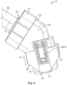
- Figure 5 shows the mating connector 6 embodied as the header 6a with the mating connector housing 5, comprising an outer housing 43 which receives a mating connector insert 45.
- the mating connector insert 45 is embodied as a header insert 46 comprising an inner mating connector housing 47 which is encircled by a shield 49.
- the mating connector housing 5 is embodied as a header housing 5a.
- a contact element 51 is shown as well wherein a first contact element 51 a extends from the contact-side receptacle 25 into the contact direction 21, the first contact element 51 a, being one of the electric contact elements, furthermore extends into the inner mating connector housing 47.
- a second contact element 51 b is visible in Figure 5 , said second contact element 51 b is a monolithic element as well and also extends in the contact direction 21 out of the contact-side receptacle 25 which is, however, not visible due to the flange 15.
- the header insert 46 is centered in the connection-side receptacle 39, forming a mating clearance 53 which is a free space between the header insert 46 and the outer housing 43.
- Figure 5 furthermore shows guiding members 55 which are configured to be received in guiding grooves 57 ( Figure 4 ) in order to guide the connector housing 3 when plugged along the plug direction 11 with the mating connector housing 5.
- the two housings also show a connector position assurance 59 which is embodied as a locking latch 61 at the connector housing 3 ( Figure 4 ) and a detent hook 63 at the mating connector housing 5 ( Figure 5 ).
- a connector position assurance 59 which is embodied as a locking latch 61 at the connector housing 3 ( Figure 4 ) and a detent hook 63 at the mating connector housing 5 ( Figure 5 ).
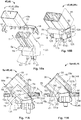
- Figure 6 illustrates the assembly of a connector insert 67, showing a pre-assembly state 69a in Figure 6(A) , an inserted state 69b in Figure 6(B) and a final state 69c in Figure 6(C) .
- the connector insert 67 comprises a shield 49, the inner connector housing 35 and the cable 33 which comprises an unshielded region 71 in which the cores 73 of the cable 33 are visible.
- the embodiment of the cable shown in Figure 6 is thus a two-core cable, however, any multi-core cable may be used.
- the lead-wires (not shown in Figure 6 , see Figure 12 ) of the two cores 73 are received in the inner connector housing 35, whereas the cable 33 is oriented in the cable direction 19 and the inner connector housing 35 is oriented along the plug direction 11.
- Both said directions are at an angle of 45° to each other, whereas the two cores 73 provide the necessary bending by 135° in the unshielded region 71.
- the connector insert 67 further comprises the cable seal retainer 41, a cable seal 75, an outer crimp ferrule 77 and an inner crimp ferrule 79.
- the outer crimp ferrule is a retaining element 78.
- the shield 49 shown in Figures 6(A) and (B) is in a first crimp state 81 a, in which an inner housing recess 83 is enclosed by a first portion 85 of the shield 49.
- the shield 49 furthermore comprises a hood portion 87, which is attached to the first portion 85 at a hinge line 89 and which is oriented along the plug direction 11.
- Figure 6 further shows two wing portions 91 which are monolithically attached to the first portion 85 of the shield 49 and which are adapted and pre-formed to be oriented along the cable direction 19 if the first portion 85 encloses the inner housing recess 83.
- shields 49 are shown in more detail.
- the hood portion 87, as well as the wing portions 91, show abutting edges 93.
- the first portion 85 also comprises two abutting edges 93 which are, however, not visible in Figure 6 (see Figures 8 and 9 ).
- the shield 49, as well as the inner connector housing 35 comprise locking members 95 which are used to lock the position of both elements when assembled.
- the inner connector housing 35 and the cores 73 are inserted into the shield 49 along the plug direction 11.
- the inner connector housing 35 is received in the inner housing recess 83 and the cores 73 as well as parts of the cable 33 are received in a cable recess 97 which is formed by the hood portion 87 and the wing portions 91.
- the unshielded region 71 of the cable 33 that is the region exposing the cores 73, is entirely located in the cable recess 97 and thus electro-magnetically shielded by the shield 49.
- the shield 49 being in a final crimp state 81 b ( Figure 6(C) ), receives the inner crimp ferrule 79 in the cable recess 97 and the outer crimp ferrule 77, which is the retaining element 78, partially encircles the wing portions 91 and the hood portion 87.
- the outer crimp ferrule locks and/or secures the shield by preventing the cable recess 97 to be opened again.
- the hood portion 87 and the wing portions 91 enclosed by the retaining element 78 are entirely received in the cable-side receptacle 23 and oriented along the cable direction 19.
- the first portion 85 of the shield 49 is oriented along the plug direction 11.
- Figure 7 shows the connector insert 67 and the outer housing 43 of the connector housing 3, in a first receiving phase 99a ( Figure 7(A) ), and a third receiving phase 99b ( Figure 7(B) ) wherein the outer housing 43 is shown as a cut revealing the cable-side receptacle 23 and the connection-side receptacle 39.
- the connector insert 67 comprises a connector-side portion 127 and a cable-side portion 128.
- the connector insert 67 is inserted into the cable-side receptacle against the cable direction 19, which is indicated by a dashed line of movement 101, along which one corner 103 of the connector insert 67 moves during the first receiving phase 99a until said corner 103 touches an insight wall 105 of the outer housing 43.
- Figure 7(B) shows the connector insert 67 and the outer housing 43 at the end of the third receiving phase 99b in which the first portion 85 of the shield 49 is entirely received in the connection-side receptacle 39 and the cable 33.
- the connector insert 67 is rotated around the hinge line 89 and the insertion direction 107 is oriented opposite to the cable direction 19 during the first receiving phase 99a and along the plug direction 11 during the third receiving phase 99b.
- the insertion direction 107 is rotated by 45° about the hinge line 89 from the direction opposite to the cable direction 19 to the plug direction 11.
- Figure 7(B) also illustrates that a clearance 109 between the connector insert 67 and the cable-side receptacle 23 is larger than between the connector insert 67 and the connection-side receptacle 39.
- Figure 7 also shows the guiding grooves 57 in which the guiding member members 55 of the mating connector housing 5 (see Figure 3 ) are guided.
- a detent hook 63 which is attached to a flexible arm 111, extends into the guiding groove 57.
- said detent hook 63 abuts the guiding member 55 of the mating connector housing 5 and deflects the flexible arm 111 away from the connection-side receptacle 39 and upon sufficient insertion of the housing 3, 5 into each other, the detent hook 63 engages behind the guiding member 55, thus locking both housings 3, 5 to each other.
- connection-side receptacle 39 furthermore comprises the connector position insurance element 59 and is surrounded by a seal receptacle 113 which is adapted to receive the peripheral seal 149 (not shown) and the peripheral seal retainer 37 (not shown).
- Figures 8 and 9 show two embodiments of the shield 49, whereas the shield 49a is adapted to be used in the connector housing 3 and the shield 49b is adapted to be used in the mating connector housing 5.
- Both shields 49 are pre-formed, that is for instance the wing portions 91 of the shield 49a are bent, or the first portion 85 of the shield 49b already forms an inner mating housing recess 115.
- FIGs 8 and 9 also show the hinge line 89 which is enlarged in a zoom box 117 revealing the structure of the hinge line 89.
- the embodiment of the hinge lines 89 shown in Figures 8 and 9 comprise a weakening line 121 introduced by a multitude of drill holes 119 oriented along the weakening line 121 indicated by a dashed line.
- Figure 8 also shows the first wing abutting edges 93a of the shield 49a whereas the abutting edges 93 of the hood portion 87 and the first abutting edges 93a of the wing portions 91 are formed complementary to each other.
- the second wing abutting edges 93b are formed complementary to each other.
- the shield 49a furthermore comprises several resilient clamping legs 94 which are adapted to primarily establish electrical contact with sufficient normal force between the shields. Further, they may increase the mechanical release force to unplug the connector 4 from the mating connector 6, and they may also act as locking members 95 in the form of detent hooks 63 or as locking recesses 123.
- the order of the above given effects may vary according to a particular embodiment of the invention.
- the second embodiment of the shield 49b shown in Figure 9 also has the first portion 85, the hood portion 87 and two wing portions 91.
- the first portion 85 is similar for both shields 49a, 49b.
- the abutting edges 93 of the first portion 85 and the wing portions 91 are at least partially complementary to each other.
- the shield 49b furthermore comprises two weakening lines 121 oriented perpendicular to the hinge line 89, and a multitude of resilient clamping legs 94 extending from the hood portion 87 and the wing portions 91 away from the first portion 85. Said clamping legs 94 are adapted to establish electrical contact with sufficient normal force between the shield and a machine wall.
- Figure 10 shows the mating connector insert 45 embodied as the header insert 46 in the pre-assembly state 69a and in the inserted state 69b.
- the inner mating connector housing 47 and the shield 49a are moved towards each other along or against the plug direction 11, wherein a connector-side portion 127 of the header insert 46 is received in the inner mating housing recess 115 and a contact-side portion 129 is at least partially encircled by the hood portion 87 and the wing portions 91 of the shield 49a.
- the abutting edges 93 of the first portion 85 and the wing portions 91 at least partially abut each other because they are complementary to each other.
- the resilient clamping legs 94 are in engagement with the contact-side portion 129 of the header insert 46.
- the engagement may be a position or a frictional engagement.
- Figure 10 also shows contact elements 51 extending from the connector-side portion 127 to the contact-side portion 129 from which they extend in the contact direction 21.
- the guiding member 55 is shown as well, and its particular shape will be explained with reference to Figure 11 .
- the insertion of the header insert 46 into the mating connector housing 5, embodied as the header 5a, is shown in the first receiving phase 99a ( Figure 11 (A) ) and a second receiving phase 99c ( Figure 11 (B) ).
- the header insert 46 is inserted into the contact-side receptacle 25 along the plug direction 11.
- the header insert 46 passes the contact-side receptacle 25 and is received by the connection-side receptacle 39.
- the first portion 85 of the header insert 46 glides along and is guided by the inside wall 105 of the connection-side receptacle 39.
- the movement of the guiding member 55 is indicated by a dashed line illustrating a distance 131, which may also be measured between the hinge line 89 and a second mechanical contact point 135.
- header insert 46 is inserted into the header 5a over the distance 131, a further movement along the plug direction is prevented as the guiding member 55 touches the header 5a at the mechanical contact point 133.
- the end of the phase is shown in Figure 11 (B) .
- the header insert 46 is further inserted into the header 5a in a direction opposite to the contact direction 21. This movement of the header insert 46 is guided by a guide wall 137 of the guide member 55, which slides along and is guided by a second guide wall 137a located inside the contact-side receptacle 25 of the header 5a.
- the header insert 46 is inserted completely into the header 5a, that is the hinge line 89 touches the third mechanical contact point 141, the particular shape of the guiding member 55, located on one side of the mating connector inserts 45 contact-side portion 127, complements the shape of the inside wall 105 of the connection-side receptacle 39.
- Figure 11 furthermore shows the above-mentioned seal groove 143 which is adapted to receive the axial seal 17 (not shown), the through-holes 15a adapted to receive the seal pins 17a (not shown) and the guiding members 55 at the opening of the connection-side receptacle 39 adapted to be guided inside the guiding grooves 57 (not shown) of the connector housing 3.
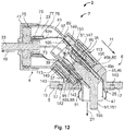
- Figure 12 shows the electrical connector assembly 2 in a cut, whereas the cut is performed along a plane in which one contact element 51 is located.
- the electrical connector assembly 2 comprises the electrical connector 4 and the electrical mating connector 6.
- the electrical connector assembly 2 is shown in the first position 7, meaning that the angle between the cable direction 19 and the contact direction 21 is 90°.
- the cable 33 is inserted into the cable-side receptacle 23 in a direction opposite to the cable direction 19.
- the opening of the cable-side receptacle 23 is sealed by a cable seal 75 which is adapted to enclose the cable 33 and adapted to be located inside the cable-side receptacle 23.
- the cable seal 75 abuts against the cable seal retainer 41, by which the cable seal 75 is held.
- the cable seal 75 may also abut the outer crimp ferrule 77, the inner crimp ferrule 79 and the shield 49a.
- Each core 73 itself has an insulation whereas this particular insulation is only removed to establish an electrical connection with a contact element 51 embodied as a plug socket 147.
- the lead-wires 149 of the cores 73 are attached to the plug socket 147, for instance by clamping or welding.
- the inner connector housing 35 is received in the connection-side receptacle 39 of the shield 49a, abutting the shield 49a at its inside wall 105 and at the hinge line 89.
- peripheral seal retainer 37 abuts the peripheral seal 149 and the shield 49a, preventing both elements to be unintentionally removed from the electrical connector 4 in the plug direction 11 before reaching the first position 7.
- the resilient clamping legs 94 of the shield 49a abut against the shield 49b, more precisely against the first portion 85 of the shield 49b.
- the peripheral seal retainer 37 is inserted into the connection-side receptacle 39 of the mating connector housing 5 and is located between the header insert 46 and the inside wall 105 of the connection-side receptacle 39.
- connection-side receptacle 39 is offset-free in the wall regions 142, the insertion of the peripheral seal retainer 37 into the connection-side receptacle 39 is not prevented or blocked.
- the header insert 46 comprises the inner mating connector housing 47 and the shield 49b is firmly held in the contact-side receptacle 25 of the mating connector housing 5.
- An electrical connection between the connector housing 3 and the mating connector housing 5 is established by the contact element 51 of the mating connector housing 5, embodied as a tab 151 which is monolithically embodied and has an angle of 135° between its tip 153 and its end 155.
- the tip 153 of the tab 151 shows a chamfer for easy insertion into the plug socket 147.
- the tab 151 is inserted into the inner mating connector housing 47 against the plug direction 11 shown in Figure 12 .
- Figure 12 further shows that the wing portions 91 of the shield 49b do not entirely abut the first portion 85 of the shield 49b and that the axial seal 17 is received in the seal groove 143 sealing the flange 15 against a wall which is not shown.
Landscapes
- Details Of Connecting Devices For Male And Female Coupling (AREA)
- Connector Housings Or Holding Contact Members (AREA)
Abstract
Description
- The invention relates to a connector housing assembly for an electrical connector, comprising a connector housing and a mating connector housing, which are configured to be connected to each other in a first position at a respective connecting section by being moved along a plug direction towards each other, the connector housing further comprising a cable-side receptacle for a cable, the receptacle opening in a cable direction and the mating connector housing comprising a contact-side receptacle for a cable and/or at least one contact element, the receptacle opening in a contact direction, both receptacles being located at an end opposite the connecting section in the respective connector housing.
- The invention furthermore relates to an electrical connector assembly comprising an electrical connector with a connector housing and an electrical conductor within the connector housing, an electrical mating connector with a mating connector housing and a mating electric conductor. The connectors are configured to be connected to each other in a first position at a respective connecting section by being moved along a plug direction towards each other, the connector housing further comprising a cable-side receptacle opening in a cable direction and receiving the electric conductor, and the mating connector housing comprising a contact-side receptacle opening in a contact direction and receiving the mating electric conductor, both receptacles being located at an and opposite the connecting section in the respective connector housing.
- Connector housing assemblies are known from the prior art. If they are configured for an electrical angle connector, they are constructed for being plugged in a first position and are not adapted to be utilized in a configuration allowing a different plug angle. In order to obtain a different plug angle, another connector housing assembly or at least another additional connector housing has to be applied.
- In case of an electrical connector with a plug angle of 90°, the contact pins may not be inserted into the connector housing from the cable-side. Therefore, contact pins of the prior art either require several parts or demand being molded into the connector housing. A contact pin comprising several parts has a higher contact resistance resulting in a decrease of the power that can be transmitted by such an angle plug.
- Furthermore, if an angle of 180° is desired, an additional 90° plug needs to be incorporated into the system. The additional element also increases the contact resistance.
- Hence, solutions of the prior art require many parts resulting in increased costs and also in an increased contact resistance.
- The object of the invention is therefore to provide a connector housing assembly which may be versatilely applied in different plug positions without demanding for additional elements.
- Furthermore, the object of the invention is to provide an electrical connector assembly that can be adapted to have an angle between contact pins and/or a cable of a mating connector and the cable of the electrical connector of either 90° or 180° without the need for additional elements and without increasing the contact resistance of the electrical connector assembly.
- These objects are achieved for the inventive connector housing assembly in that the connector housing assembly comprises a connector housing and a mating connector housing which are adapted to be plugged together in a second position, wherein in the second position one of the connector housing or the mating connector housing is rotated about the plug direction compared to the first position. In the inventive connector housing assembly, in the first position, the cable direction and the contact direction are substantially perpendicular to each other, whereas in the second position, the cable direction and the contact direction are substantially parallel to each other.
- The inventive electrical connector assembly solves the above-mentioned problem by providing a connector housing and the mating connector housing which are adapted to be plugged together in a second position, wherein in the second position one of the connector housing or the mating connector housing is rotated about the plug direction compared to the first position and in that, in the first position, the electric conductor received in the cable-side receptacle and the mating electric conductor received in the contact-side receptacle are substantially perpendicular to each other, whereas in the second position, they are substantially parallel to each other.
- In the following, further advantageous embodiments of the invention are described. Individual features, each being advantageous on their own, may arbitrarily be combined with each other.
- In a preferred embodiment of the connector housing assembly, the cable direction and the plug direction are at an angle of at least approximately 45° to each other and/or the contact direction and the plug direction are at an angle of at least approximately 45° to each other.
- It is preferable if both housings yield an angle of at least approximately 135° between their receptacles.
- If the same angle of at least approximately 135° is provided between the two receptacles of each housing, in the first position the two equal angular changes in direction of at least approximately 45° may add up to a change in direction of at least approximately 90°.
- On the other hand, if the two housings with an angle of at least approximately 135° between the housing receptacle are plugged together in the second position, the angular change in direction introduced by the connector housing may compensate for the angular change in direction introduced by the mating connector housing as the angular change in direction is opposite for both housings.
- By choosing different angles between (a) the cable direction and the plug direction and (b) the contact direction and the plug direction, plug positions may be obtained, wherein the obtained cable direction and contact direction may be at an angle different than 90° and 180°. However, in both possible positions the angles between the cable direction and the contact direction are not equal as in solutions of the prior art.
- In a first advantageous embodiment of the electrical connector assembly, a connector insert and/or a mating connector insert is provided which is/are adapted to be inserted into the according housing against the cable direction and/or the contact direction respectively, the connector insert comprising a cable-side portion and a connector-site portion, the mating connector insert comprising a contact-side portion and a connector-side portion, the connector insert and/or the mating connector insert extending, if mounted to the according housing, from the connecting section to the receptacle being located at an end opposite the connecting section in the respective housing.
- Different means of mounting the connector insert into the connector housing and/or the mating connector insert into the mating connector housing are possible. Both housings may be embodied as one part.
- In case of a one-piece housing, the connector insert is, for instance, inserted into the connector housing from either the cable-side or from the connection-side which is defined as the side towards which the receptacle located at the connecting section opens.
- The mating connector insert may similarly be inserted into the mating connector housing, that is either from the connection-side or from the cable-side.
- Furthermore, the connector housing and/or the mating connector housing may comprise two parts, wherein during assembly of the connector insert and/or the mating connector insert, said insert is inserted into one part of the respective housing and the second part of the respective housing may be attached to the first part of the respective housing by closing the housing.
- Another possibility to incorporate the connector insert and/or the mating connector insert into the respective housing, is to directly mold the connector insert and/or the mating connector insert into the respective housing, that is the respective housing is molded around the connector insert and/or the mating connector insert.
- In another advantageous embodiment of the inventive electrical connector assembly, the cable-side portion and the connection-side portion of the connector insert and/or the contact-side portion and the connection-side portion of the mating connector insert are at an angle of at least approximately 135° to each other.
- It is to be noted that the term "at least approximately 135°" expresses the fact that a certain variation in the angle spanned by the portions of the insert may not be exactly 135° but may vary within the range of +/- several degrees.
- It is preferable that the connector insert and the mating connector insert feature the same angle between the respective portions of the insert. If angles between the cable direction and the contact direction deviating from 90° or 180° are preferred, the angles between the different portions of the insert may differ than said 135°.
- Angles between the cable direction and the contact direction deviating from 90° and 180° may also be obtained if one of the connector inserts or the mating connector inserts feature two portions being at an angle of at least approximately 135°, wherein the portions of the corresponding second insert maybe at a substantially different angle.
- The cable-side portion of the connector insert and/or the contact-side portion of the mating connector insert may comprise solely a stripped part of the cable. This stripped part may comprise exposed cores of said cable. Said cores of the cable may provide a necessary bending in order to obtain the angle of at least approximately 135°. However, the connector insert and/or the mating connector insert may be embodied as an individual part comprising two portions which are at a fixed angle of at least approximately 135° to each other.
- The connector insert and/or the mating connector insert may comprise a bending region allowing to set an angle between the two portions of the corresponding insert. In this case, the cores of the stripped cable may either be attached to an already bent region of the insert or may be passively bent with one portion of the corresponding insert.
- In another embodiment of the electrical connector assembly, it is advantageous if the connector insert and/or the mating connector insert comprise a shield with a cable recess for receiving the cable and an inner housing recess for receiving an inner connector housing and/or an inner mating connector housing in the according housing, the cable recess and the inner housing recess are at an angle of at least approximately 135° to each other.
- It is preferable if the shield shows the same angle as the insert it encircles. By means of the same angle, the clearance between the insert and the shield may be minimized, also minimizing the space required by such an electrical connector assembly.
- The shield of the connector insert and/or the mating connector insert may completely encircle the corresponding insert. The shield, however, may also be adapted according to the environment it is applied to.
- If for instance, one of the connector housing or the mating connector housing is installed partially inside or behind a wall of a machine or a device, shielding of only one side of the insert by the shield may be sufficient, as the wall of the device or the machine may also feature shielding against electromagnetic crosstalk or parasitic coupling.
- The shields applied in the electrical connector and/or in the electrical mating connector may be substantially the same, they may also be slightly or completely different.
- The shields may be used to shield a stripped cable portion located inside the corresponding connector housing. As a multi-wire cable is, in general, shielded against electromagnetic crosstalk, the shields may guarantee a continuous shielding of the whole electric circuit even if a part of the insulation shielding of the multi-core cable is removed for establishing an electronic connection. This striped cable portion may be encircled and shielded by the shield.
- The shields may comprise resilient clamping legs that may be used to establish electrical contact with sufficient normal force between the shields or between the shield and a machine wall.
- Furthermore said resilient clamping legs may increase the mechanical release force which may be necessary to unplug the connector from the mating connector or may also act as locking members.
- It is conceivable that any combination of the effects given above may occur in an embodiment of the invention.
- In another preferred embodiment of the inventive electrical connector assembly, the shield of the connector insert and/or the shield of the mating connector insert comprise a hood portion.
- The hood portion may be a separate element which may be attached and/or fixed to the shield in order to complement the shielding by the shield.
- As the shield comprises different recesses for receiving a cable and/or an inner housing or an inner mating connector housing, assembly of said elements may largely be facilitated by means of a hood portion, which is brought into its shielding position only after said elements where inserted into the shield.
- Therefore, a hood portion, which is adapted to be removable and assembled to the shield after insertion of different elements, allows for insertion of a cable, an inner connector housing, or an inner mating connector housing - both elements may be at an angle of at least approximately 135° - without the need of a large clearance between the inserted elements and the shield.
- The hood portion may allow for easy installation of a bent cable and/or bent inner connector housing and/or a bent inner mating connector housing into the bent shield, wherein the inserted elements may be fitted tightly into the shield, and the shielding against electromagnetic crosstalk is complemented by attaching the hood portion onto the opening where said elements were inserted into the shield.
- In another embodiment of the inventive electrical connector assembly, it is advantageous if the hood portion is tiltable about a hinge line, the hinge line being a weakening line.
- The hood portion and the shield itself may be a monolithic stamped and bent part made of a sheet metal.
- If the hood portion is attached to the shield by means of a hinge, the hood portion may not be lost as in the case of a separate element.
- It is advantageous if the hinge line is a weakening line because such a weakening line may be easily generated during stamping or bending of the sheet metal, therefore facilitating the production of the hinge.
- The weakening line furthermore allows to assemble the shield easily by hand, as the weakening line represents a predetermined structure along which bending of the sheet metal will occur if bending forces are applied.
- The weakening line may be embodied as a line with decreased material thickness as compared to the rest of the sheet metal, or as a line along which the sheet metal comprises drill holes, notches, depressions or similar structures of the sheet metal decreasing the strength of the sheet metal within the well-defined area of said structures.
- In another advantageous embodiment of the inventive electrical connector assembly a retaining element is provided which is adapted to retain and/or secure the shield.
- If the hood portion of the shield is tilted during the assembly of the shield in such a way that it is completely shielding the comprised elements, like for instance cables, the inner connector housing or the inner mating connector housing, it is preferable if the hood portion is fixed and/or secured in this shielding position.
- The retaining element may be embodied as a clip fixing the hood portion to the shield, the retaining element may also be embodied as a ring which is put above the shield and the hood portion in order to retain and/or secure the shield in the shielding position.
- Furthermore the retaining element may be embodied as a latch or a retaining hook at the hood portion which is locked to a complementary retaining detent hook or latch of the shield.
- In another embodiment of the electrical connector assembly it is advantageous if the clearance
- between the connector insert and the connector housing and/or
- between the mating connector insert and the mating connector housing
- Such clearances may be helpful if the connector insert and/or the mating connector insert are inserted into the corresponding housing from the side featuring the larger clearance.
- Such a clearance may allow to insert a connector insert and/or a mating connector insert which is embodied as one single part.
- In order to insert the connecting side portion of the corresponding insert into the receptacle being located at respectively in the connecting section, a tilting movement may be applied to reach the final assembly position of the connector insert and/or the mating connector insert. This tilting movement, however, may be easily performed if the portion of the connector insert and/or the mating connector insert located at the end opposite the connecting section in the respective housing has a sufficient clearance.
- In another advantageous embodiment of the electrical connector assembly the connector insert and/or the mating connector insert are adapted to be inserted into the according housing from the end opposite the connecting section of the according housing and are preferably adapted to be snapped or clipped into place.
- Snapping or clipping of the connector insert and/or the mating connector insert into the corresponding housing may be achieved by means of a form fit of the connector insert and the connector housing, respectively a form fit between the mating connector insert and the mating connector housing.
- Said combinations of insert and housing are characterized by the before-mentioned clearance between the insert and the corresponding housing.
- In order to be snapped into place, the insert and/or the mating connector insert may comprise a locking member adapted to be locked to a counter-locking member of the connector housing and/or the mating connector housing.
- When snapped or clipped into place, the engagement of the lock between the insert and/or the mating connector insert with the corresponding housing may be signalized by an optical and/or acoustical and/or haptic feedback of the electrical connector assembly to the user.
- In another embodiment of the inventive electrical connector assembly, it is advantageous if the mating connector is a header and the mating connector housing is a header housing.
- The header may be adapted to be attached to a wall of a machine or a device, wherein a flange may be comprised in order to attach the header to said wall.
- As the wall of the machine or the device partially shield electrically conducting elements reaching into the machine or device, the shield of the header may be adapted to only partially shield said element reaching into the machine or device.
- The flange may further be adapted to comprise an axial seal in order to seal the header opening in the wall of the machine or device against fluids and dust entering the machine or device.
- In another preferred embodiment of the electrical connector assembly the mating connector insert is a header insert extending from the contact-side receptacle of the mating connector housing to the connecting section.
- The header insert may be inserted into the header housing similar to the above-described connector insert to the connector housing. The header insert may be inserted by a combination of a linear and a tilted movement, but it is also possible that the header insert is inserted into the header housing by means of two linear movements along the plug direction and a direction opposite to the contact direction.
- The header insert may comprise a guiding element which provides at least one mechanical contact point along which the header insert is guided during insertion into the header housing.
- In another embodiment of the inventive electrical connector assembly it is advantageous if the mating connector insert is a header insert extending from the contact-side to the receptacle of the mating connector housing to the connecting section.
- It is preferred that said header insert is embodied as a single part, that is, the header insert is not comprising two or more separate parts which are brought into contact during assembly.
- In another advantageous embodiment of the electrical connector assembly electrically conducting tabs are provided, the tabs having an angle of at least approximately 135° and being adapted to be inserted into the header insert in the plug direction.
- The before-mentioned electrical conductors may be embodied as either a cable or tabs wherein tabs are preferred in the header and cables are preferred in different electrical connectors.
- The tabs applied to the header may be embodied as a stamped and bent sheet metal part, that is, they may be monolithic without demanding for connecting two parts to each other for obtaining the angle of at least approximately 135°.
- The header insert may be adapted to have a contact-side portion which allows insertion of the tabs bent by at least approximately 135° along the plug direction, thus, assembly of the tabs into the header may be performed in a linear direction without a tilting motion.
- Such monolithic tabs are advantageous because the contact resistance is not increased by means of another electrical contact point.
- The tabs may be embodied with a chamfer at the tip of the tab in order to facilitate insertion of the tab or tabs into the electrical contact sockets of the electrical connector.
- In another embodiment of the inventive electrical connector assembly it is advantageous if the header housing is adapted to receive the header insert from the contact side.
- Insertion of the header insert from the contact side into the header housing may be performed in two linear movements during two different receiving phases.
- The assembly of the header insert to the header housing may be finalized by engaging both elements in a form fit which may be achieved by a complementary shape of the connection-side receptacle and/or the contact-side receptacle of the header housing and the header insert.
- In the following the invention is described with reference to the attached drawings, whereas at least a part of the above-described features are incorporated in the embodiment or embodiments shown in the figures. Individual features of the described embodiment or the described embodiments may be left out according to the explanation above, if the advantage related to that feature is not relevant for a particular application. Equally the described embodiment may additionally comprise the above-described features if the particular application requires the respective.
- In the figures same elements and elements with the same function and/or structure are labeled with the same reference signs.
- In the drawings:
- Fig. 1
- shows an electrical connector of the prior art;
- Fig. 2
- shows a connector housing assembly in a first position;
- Fig. 3
- shows a connector housing assembly in a second position;
- Fig. 4
- shows a connector housing with a connector insert installed;
- Fig. 5
- shows a mating connector housing with a mating connector insert installed;
- Fig. 6
- the assembly of the connector insert;
- Fig. 7
- shows the insertion of the connector insert into the connector housing;
- Fig. 8
- shows a first embodiment of a shield;
- Fig. 9
- shows a second embodiment of the shield;
- Fig. 10
- shows the assembly of the mating connector insert;
- Fig. 11
- shows the insertion of the mating connector insert into the mating connector housing; and
- Fig. 12
- shows a cut of an electric connector
-
Figure 1 shows anelectrical connector assembly 2 of the prior art. More precisely, two possibleelectrical connector assemblies 2 are shown, both comprising each anelectrical connector 4 and amating connector 6. Theelectrical connector 4 comprises anelectric conductor 157 which is embodied as acable 33 and themating connector 6 comprises anelectric mating conductor 159 which may be embodied as a contact element (not shown). -
Figure 1 shows twodifferent connectors housings 3 which are used for the connectors 4.The connector housing 3a is a 90° connector housing and connector housing 3b is a 180° connector housing. Both connector housings 3a, 3b are configured to be plugged to themating connector housing 5 embodied as aheader housing 5a, which is used for themating connector 6. -
Figure 1 illustrates one disadvantage of the state of the art connector housing assemblies 1. To change the angle provided by the connector housing assembly 1, one of theconnector housing 3 or themating connector housing 5 has to be replaced by a different embodiment of the respective housing. -
Figure 2 andFigure 3 both show the connector housing assembly 1, wherein theconnector housing 3 and themating connector housing 5 are connected to each other in afirst position 7 inFigure 2 , and in a second position 9 inFigure 3 . - As the connector housing assembly 1 has the same elements independent of the
plug position 7, 9,Figure 2 andFigure 3 are described together, wherein differences due to theplug position 7, 9 are indicated accordingly. - The
connector housing 3 and themating connector housing 5 have been plugged together along aplug direction 11 forming a connectingsection 13. Theplug direction 11 for theconnector housing 3 and themating connector housing 5 are parallel to each other but opposite in their direction. - The
mating connector housing 5 shown inFigures 2 and3 is embodied as aheader 5a comprising aflange 15 which is adapted to attach theheader 5a to a wall (not shown) by means of fixation openings (not shown inFigures 2 or3 , seeFigure 5 ). - An
axial seal 17 is shown inFigures 2 and3 as well. Theaxial seal 17 is located on the contact-side of theheader 5a and it is applied to seal a wall opening (not shown) against fluids and dust. - The
axial seal 17 is held in the correct position by means ofseal pins 17a, the seal pins 17a extending from theaxial seal 17 against acontact direction 21, are received in through-holes 15a of theflange 15. - The
axial seal 17 is received in a seal groove (shown inFigure 12 ) located at the contact-side of theflange 15. -
Figures 2 and3 further show acable direction 19 and thecontact direction 21 which are drawn again in the upper left corner of the respective Figure to illustrate that in thefirst position 7, thecable direction 19 and thecontact direction 21 are perpendicular to each other (Figure 2 ), whereas in the second position 9, thecable direction 19 and thecontact direction 21 are parallel to each other (Figure 3 ). Thecontact side 22 is shown as well. - In
Figures 2 and3 , the cable-side receptacle 23 and a contact-side receptacle 25 are illustrated. Said receptacles (not visible) are oriented along the respective direction, that is thecable direction 19 or thecontact direction 21. In the second position 9 shown inFigure 3 , the cable-side receptacle 23 and the contact-side receptacle 25 are oriented parallel to each other but the cable-side receptacle 23 is offset laterally by an offsetdistance 27 in anx-direction 29. - In
Figure 4 , theelectrical connector 4 is shown. Theelectrical connector 4 comprises theconnector housing 3 shown in an assembled state 31, that is, it is prepared to be used in establishing an electrical connection with the corresponding mating connector. - The
electrical connector 4 comprises thecable 33 which is received in the cable-side receptacle 23 of theconnector housing 3 against thecable direction 19, aninner connector housing 35 which is enclosed by aperipheral seal retainer 37, theinner connector housing 35 is received in a connection-side receptacle 39 which will be shown in more detail in the following figures. - The
cable 33 is centered and fixed by acable seal retainer 41 which is put over anouter housing 43 and which holds a cable seal (not shown) sealing the inside of theouter housing 43 against fluids and dust. -
Figure 5 shows themating connector 6 embodied as the header 6a with themating connector housing 5, comprising anouter housing 43 which receives a mating connector insert 45. - The mating connector insert 45 is embodied as a header insert 46 comprising an inner
mating connector housing 47 which is encircled by ashield 49. Themating connector housing 5 is embodied as aheader housing 5a. - A
contact element 51 is shown as well wherein a first contact element 51 a extends from the contact-side receptacle 25 into thecontact direction 21, the first contact element 51 a, being one of the electric contact elements, furthermore extends into the innermating connector housing 47. - A
second contact element 51 b is visible inFigure 5 , saidsecond contact element 51 b is a monolithic element as well and also extends in thecontact direction 21 out of the contact-side receptacle 25 which is, however, not visible due to theflange 15. - The header insert 46 is centered in the connection-
side receptacle 39, forming amating clearance 53 which is a free space between the header insert 46 and theouter housing 43.Figure 5 furthermore shows guidingmembers 55 which are configured to be received in guiding grooves 57 (Figure 4 ) in order to guide theconnector housing 3 when plugged along theplug direction 11 with themating connector housing 5. - The two housings also show a
connector position assurance 59 which is embodied as a locking latch 61 at the connector housing 3 (Figure 4 ) and adetent hook 63 at the mating connector housing 5 (Figure 5 ). - In
Figure 5 , the seal pins 17a of theaxial seal 17 as well asfixation openings 65 are shown. -
Figure 6 illustrates the assembly of aconnector insert 67, showing apre-assembly state 69a inFigure 6(A) , an insertedstate 69b inFigure 6(B) and afinal state 69c inFigure 6(C) . - The
connector insert 67 comprises ashield 49, theinner connector housing 35 and thecable 33 which comprises anunshielded region 71 in which thecores 73 of thecable 33 are visible. The embodiment of the cable shown inFigure 6 is thus a two-core cable, however, any multi-core cable may be used. - The lead-wires (not shown in
Figure 6 , seeFigure 12 ) of the twocores 73 are received in theinner connector housing 35, whereas thecable 33 is oriented in thecable direction 19 and theinner connector housing 35 is oriented along theplug direction 11. - Both said directions are at an angle of 45° to each other, whereas the two
cores 73 provide the necessary bending by 135° in theunshielded region 71. - The
connector insert 67 further comprises thecable seal retainer 41, acable seal 75, an outer crimp ferrule 77 and aninner crimp ferrule 79. The outer crimp ferrule is a retaining element 78. - The
shield 49 shown inFigures 6(A) and (B) is in a first crimp state 81 a, in which aninner housing recess 83 is enclosed by afirst portion 85 of theshield 49. Theshield 49 furthermore comprises ahood portion 87, which is attached to thefirst portion 85 at ahinge line 89 and which is oriented along theplug direction 11. -
Figure 6 further shows twowing portions 91 which are monolithically attached to thefirst portion 85 of theshield 49 and which are adapted and pre-formed to be oriented along thecable direction 19 if thefirst portion 85 encloses theinner housing recess 83. InFigures 8 and9 , shields 49 are shown in more detail. - The
hood portion 87, as well as thewing portions 91, show abutting edges 93. Thefirst portion 85 also comprises two abuttingedges 93 which are, however, not visible inFigure 6 (seeFigures 8 and9 ). - The
shield 49, as well as theinner connector housing 35 comprise lockingmembers 95 which are used to lock the position of both elements when assembled. - In the inserted
state 69b (Figure 6(B) ), theinner connector housing 35 and thecores 73 are inserted into theshield 49 along theplug direction 11. Theinner connector housing 35 is received in theinner housing recess 83 and thecores 73 as well as parts of thecable 33 are received in acable recess 97 which is formed by thehood portion 87 and thewing portions 91. - In the inserted
state 69b, the lockingmembers 95 of theinner connector housing 35 and theshield 49 are locked to each other. - As can be seen in
Figure 6(B) , theunshielded region 71 of thecable 33, that is the region exposing thecores 73, is entirely located in thecable recess 97 and thus electro-magnetically shielded by theshield 49. - In the
final state 69c (Figure 6(C) ), thehood portion 87 was tilted around thehinge line 89 from an orientation along theplug direction 11 by 45° to an orientation along thecable direction 19. - By this tilting movement of the
hood portion 87, theunshielded region 71 and thecores 73 were completely encircled by thehood portion 87 and thewing portions 91, whereas the abuttingedges 93 of said portions are abutting each other. - The
shield 49, being in a final crimp state 81 b (Figure 6(C) ), receives theinner crimp ferrule 79 in thecable recess 97 and the outer crimp ferrule 77, which is the retaining element 78, partially encircles thewing portions 91 and thehood portion 87. The outer crimp ferrule locks and/or secures the shield by preventing thecable recess 97 to be opened again. - The
hood portion 87 and thewing portions 91 enclosed by the retaining element 78 are entirely received in the cable-side receptacle 23 and oriented along thecable direction 19. Thefirst portion 85 of theshield 49 is oriented along theplug direction 11. -
Figure 7 shows theconnector insert 67 and theouter housing 43 of theconnector housing 3, in afirst receiving phase 99a (Figure 7(A) ), and athird receiving phase 99b (Figure 7(B) ) wherein theouter housing 43 is shown as a cut revealing the cable-side receptacle 23 and the connection-side receptacle 39. - The
connector insert 67 comprises a connector-side portion 127 and a cable-side portion 128. - In
Figure 7(A) , theconnector insert 67 is inserted into the cable-side receptacle against thecable direction 19, which is indicated by a dashed line ofmovement 101, along which onecorner 103 of theconnector insert 67 moves during thefirst receiving phase 99a until saidcorner 103 touches aninsight wall 105 of theouter housing 43. -
Figure 7(B) shows theconnector insert 67 and theouter housing 43 at the end of thethird receiving phase 99b in which thefirst portion 85 of theshield 49 is entirely received in the connection-side receptacle 39 and thecable 33. - During a
second receiving phase 99c, which is not shown in the figures, theconnector insert 67 is rotated around thehinge line 89 and theinsertion direction 107 is oriented opposite to thecable direction 19 during thefirst receiving phase 99a and along theplug direction 11 during thethird receiving phase 99b. During thesecond receiving phase 99c (not shown) theinsertion direction 107 is rotated by 45° about thehinge line 89 from the direction opposite to thecable direction 19 to theplug direction 11. -
Figure 7(B) also illustrates that aclearance 109 between theconnector insert 67 and the cable-side receptacle 23 is larger than between theconnector insert 67 and the connection-side receptacle 39. -
Figure 7 also shows the guidinggrooves 57 in which the guidingmember members 55 of the mating connector housing 5 (seeFigure 3 ) are guided. - In one of the guiding
grooves 57, adetent hook 63, which is attached to aflexible arm 111, extends into the guidinggroove 57. - When the
connector housing 3 and themating connector housing 5 are plugged to each other, saiddetent hook 63 abuts the guidingmember 55 of themating connector housing 5 and deflects theflexible arm 111 away from the connection-side receptacle 39 and upon sufficient insertion of thehousing detent hook 63 engages behind the guidingmember 55, thus locking bothhousings - The connection-
side receptacle 39 furthermore comprises the connectorposition insurance element 59 and is surrounded by aseal receptacle 113 which is adapted to receive the peripheral seal 149 (not shown) and the peripheral seal retainer 37 (not shown). -
Figures 8 and9 show two embodiments of theshield 49, whereas theshield 49a is adapted to be used in theconnector housing 3 and theshield 49b is adapted to be used in themating connector housing 5. - Both shields 49 are pre-formed, that is for instance the
wing portions 91 of theshield 49a are bent, or thefirst portion 85 of theshield 49b already forms an innermating housing recess 115. -
Figures 8 and9 also show thehinge line 89 which is enlarged in azoom box 117 revealing the structure of thehinge line 89. The embodiment of the hinge lines 89 shown inFigures 8 and9 , comprise aweakening line 121 introduced by a multitude of drill holes 119 oriented along the weakeningline 121 indicated by a dashed line. -
Figure 8 also shows the firstwing abutting edges 93a of theshield 49a whereas the abuttingedges 93 of thehood portion 87 and the first abuttingedges 93a of thewing portions 91 are formed complementary to each other. The secondwing abutting edges 93b are formed complementary to each other. - The
shield 49a furthermore comprises several resilient clamping legs 94 which are adapted to primarily establish electrical contact with sufficient normal force between the shields. Further, they may increase the mechanical release force to unplug theconnector 4 from themating connector 6, and they may also act as lockingmembers 95 in the form of detent hooks 63 or as locking recesses 123. The order of the above given effects may vary according to a particular embodiment of the invention. - The second embodiment of the
shield 49b shown inFigure 9 also has thefirst portion 85, thehood portion 87 and twowing portions 91. Thefirst portion 85 is similar for bothshields first portion 85 and thewing portions 91 are at least partially complementary to each other. - The
shield 49b furthermore comprises two weakeninglines 121 oriented perpendicular to thehinge line 89, and a multitude of resilient clamping legs 94 extending from thehood portion 87 and thewing portions 91 away from thefirst portion 85. Said clamping legs 94 are adapted to establish electrical contact with sufficient normal force between the shield and a machine wall. - In
Figure 9 only one resilient clamping leg 94 is marked with a reference sign for reasons of clarity of the drawing. -
Figure 10 shows the mating connector insert 45 embodied as the header insert 46 in thepre-assembly state 69a and in the insertedstate 69b. - In the
pre-assembly state 69a (Figure 10(A) ), the innermating connector housing 47 and theshield 49a are moved towards each other along or against theplug direction 11, wherein a connector-side portion 127 of the header insert 46 is received in the innermating housing recess 115 and a contact-side portion 129 is at least partially encircled by thehood portion 87 and thewing portions 91 of theshield 49a. - In the inserted
state 69b (Figure 10(B) ), the abuttingedges 93 of thefirst portion 85 and thewing portions 91 at least partially abut each other because they are complementary to each other. - The resilient clamping legs 94 are in engagement with the contact-
side portion 129 of the header insert 46. The engagement may be a position or a frictional engagement. -
Figure 10 also showscontact elements 51 extending from the connector-side portion 127 to the contact-side portion 129 from which they extend in thecontact direction 21. The guidingmember 55 is shown as well, and its particular shape will be explained with reference toFigure 11 . - In
Figure 11 , the insertion of the header insert 46 into themating connector housing 5, embodied as theheader 5a, is shown in thefirst receiving phase 99a (Figure 11 (A) ) and asecond receiving phase 99c (Figure 11 (B) ). In thefirst receiving phase 99a, the header insert 46 is inserted into the contact-side receptacle 25 along theplug direction 11. The header insert 46 passes the contact-side receptacle 25 and is received by the connection-side receptacle 39. - During insertion of the header insert 46, the
first portion 85 of the header insert 46 glides along and is guided by theinside wall 105 of the connection-side receptacle 39. - The movement of the guiding
member 55 is indicated by a dashed line illustrating adistance 131, which may also be measured between thehinge line 89 and a secondmechanical contact point 135. - If the header insert 46 is inserted into the
header 5a over thedistance 131, a further movement along the plug direction is prevented as the guidingmember 55 touches theheader 5a at themechanical contact point 133. - During the
second receiving phase 99c, the end of the phase is shown inFigure 11 (B) . The header insert 46 is further inserted into theheader 5a in a direction opposite to thecontact direction 21. This movement of the header insert 46 is guided by aguide wall 137 of theguide member 55, which slides along and is guided by asecond guide wall 137a located inside the contact-side receptacle 25 of theheader 5a. - A similar situation can be found close to the second
mechanical contact point 135, where thehood portion 87 is guided along athird guide wall 137b which is also located inside the contact-side receptacle 25. - If the header insert 46 is inserted completely into the
header 5a, that is thehinge line 89 touches the third mechanical contact point 141, the particular shape of the guidingmember 55, located on one side of the mating connector inserts 45 contact-side portion 127, complements the shape of theinside wall 105 of the connection-side receptacle 39. - In
wall regions 142, no offset between the guidingmember 55 and theinside wall 105 is present. The insertion movement of the header insert 46 furthermore results in a centering of thefirst portion 85 of the header insert 46 with respect to the opening of the connection-side receptacle 39. -
Figure 11 furthermore shows the above-mentionedseal groove 143 which is adapted to receive the axial seal 17 (not shown), the through-holes 15a adapted to receive the seal pins 17a (not shown) and the guidingmembers 55 at the opening of the connection-side receptacle 39 adapted to be guided inside the guiding grooves 57 (not shown) of theconnector housing 3. -
Figure 12 shows theelectrical connector assembly 2 in a cut, whereas the cut is performed along a plane in which onecontact element 51 is located. Theelectrical connector assembly 2 comprises theelectrical connector 4 and theelectrical mating connector 6. - The
electrical connector assembly 2 is shown in thefirst position 7, meaning that the angle between thecable direction 19 and thecontact direction 21 is 90°. - The
cable 33 is inserted into the cable-side receptacle 23 in a direction opposite to thecable direction 19. The opening of the cable-side receptacle 23 is sealed by acable seal 75 which is adapted to enclose thecable 33 and adapted to be located inside the cable-side receptacle 23. Thecable seal 75 abuts against thecable seal retainer 41, by which thecable seal 75 is held. - The
cable seal 75 may also abut the outer crimp ferrule 77, theinner crimp ferrule 79 and theshield 49a. - Inside the
cable recess 97, thecable 33 insulation is partially removed yielding thecores 73, whereas only onecore 73 is visible inFigure 12 . - Each core 73 itself has an insulation whereas this particular insulation is only removed to establish an electrical connection with a
contact element 51 embodied as a plug socket 147. The lead-wires 149 of thecores 73 are attached to the plug socket 147, for instance by clamping or welding. - The
inner connector housing 35 is received in the connection-side receptacle 39 of theshield 49a, abutting theshield 49a at itsinside wall 105 and at thehinge line 89. - In the
seal receptacle 113 of theouter housing 43, aperipheral seal 149, theperipheral seal retainer 37 as well as part of themating connector housing 5 extending into the connectingsection 13, are received. - The
peripheral seal retainer 37 abuts theperipheral seal 149 and theshield 49a, preventing both elements to be unintentionally removed from theelectrical connector 4 in theplug direction 11 before reaching thefirst position 7. - The resilient clamping legs 94 of the
shield 49a abut against theshield 49b, more precisely against thefirst portion 85 of theshield 49b. - The
peripheral seal retainer 37 is inserted into the connection-side receptacle 39 of themating connector housing 5 and is located between the header insert 46 and theinside wall 105 of the connection-side receptacle 39. - As the connection-
side receptacle 39 is offset-free in thewall regions 142, the insertion of theperipheral seal retainer 37 into the connection-side receptacle 39 is not prevented or blocked. - The header insert 46 comprises the inner
mating connector housing 47 and theshield 49b is firmly held in the contact-side receptacle 25 of themating connector housing 5. - An electrical connection between the
connector housing 3 and themating connector housing 5 is established by thecontact element 51 of themating connector housing 5, embodied as a tab 151 which is monolithically embodied and has an angle of 135° between its tip 153 and itsend 155. The tip 153 of the tab 151 shows a chamfer for easy insertion into the plug socket 147. - The tab 151 is inserted into the inner
mating connector housing 47 against theplug direction 11 shown inFigure 12 . -
Figure 12 further shows that thewing portions 91 of theshield 49b do not entirely abut thefirst portion 85 of theshield 49b and that theaxial seal 17 is received in theseal groove 143 sealing theflange 15 against a wall which is not shown. -
- 1
- connector housing assembly
- 2
- electrical connector assembly
- 3, 3a, 3b
- connector housing
- 3a
- 90° connector housing
- 3b
- 180°connector housing
- 4
- electrical connector
- 5
- mating connector housing
- 5a
- header housing
- 6
- mating connector
- 6a
- header
- 7
- first position
- 9
- second position
- 11
- plug direction
- 13
- connecting section
- 15
- flange
- 15a
- through-hole
- 17
- axial seal
- 17a
- seal pin
- 19
- cable direction
- 21
- contact direction
- 22
- contact side
- 23
- cable-side receptacle
- 25
- contact-side receptacle
- 27
- offset distance
- 29
- x-direction
- 31
- assembled state
- 33
- cable
- 35
- inner connector housing
- 37
- peripheral seal retainer
- 39
- connection-side receptacle
- 41
- cable seal retainer
- 43
- outer housing
- 45
- mating connector insert
- 46
- header insert
- 47
- inner mating connector housing
- 49
- shield
- 49a
- first embodiment of the shield
- 49b
- second embodiment of the shield
- 51
- contact element
- 51 a
- first contact element
- 51 b
- second contact element
- 53
- mating clearance
- 55
- guiding member
- 57
- guiding groove
- 59
- connector position assurance element
- 61
- locking latch
- 63
- detent hook
- 65
- fixation openings
- 67
- connector insert
- 69a
- pre-assembly state
- 69b
- inserted state
- 69c
- final state
- 71
- unshielded region
- 73
- core
- 77
- outer crimp ferrule
- 78
- retaining element
- 79
- inner crimp ferrule
- 81 a
- first crimp state
- 81 b
- final crimp state
- 83
- inner housing recess
- 85
- first portion
- 87
- hood portion
- 89
- hinge line
- 91
- wing portions
- 93
- abutting edges
- 93a
- first wing abutting edge
- 93b
- second wing abutting edge
- 94
- resilient clamping leg
- 97
- cable recess
- 99a
- first receiving phase
- 99b
- third receiving phase
- 99c
- second receiving phase
- 101
- line of movement
- 103
- corner
- 105
- inside wall
- 107
- insertion direction
- 109
- clearance
- 111
- flexible arm
- 113
- seal receptacle
- 115
- inner mating housing recess
- 117
- zoom box
- 119
- drill hole
- 121
- weakening line
- 123
- locking recess
- 127
- connector-side portion
- 128
- cable-side portion
- 129
- contact-side portion
- 131
- distance
- 133
- mechanical contact point
- 135
- second mechanical contact point
- 137
- guide wall
- 137a
- second guide wall
- 137b
- third guide wall
- 141
- third mechanical contact point
- 142
- wall region
- 143
- seal groove
- 147
- plug socket
- 149
- peripheral seal
- 151
- tab
- 153
- tip
- 155
- end
- 157
- electric conductor
- 159
- electric mating conductor
Claims (15)
- Connector housing assembly (1) for an electrical connector assembly (2), comprising a connector housing (3) and a mating connector housing (5), which are configured to be connected to each other in a first position (7) at a respective connecting section (13) by being moved along a plug direction (11) towards each other, the connector housing (3) further comprising a cable-side receptacle (23) for a cable (33), the receptacle (23) opening in a cable direction (19) and the mating connector housing (5) comprising a contact-side receptacle (25) for a cable (33) and/or at least one contact element (51), the receptacle (25) opening in a contact direction (21), both receptacles (23, 25) being located at an end opposite the connecting section (13) in the respective connector housing (3, 5), characterized in that the connector housing (3) and the mating connector housing (5) are adapted to be plugged together in a second position (9), wherein in the second position (9) one of the connector housing (3) or the mating connector housing (5) is rotated about the plug direction (11) compared to the first position (7) and in that, in the first position (7), the cable direction (19) and the contact direction (21) are substantially perpendicular to each other, whereas, in the second position (9), the cable direction (19) and the contact direction (21) are substantially parallel to each other.
- Connector housing assembly (1) according to claim 1 characterized in that the cable direction (19) and the plug direction (11) are at an angle of at least approximately 45° to each other and/or the contact direction (21) and the plug direction (11) are at an angle of at least approximately 45° to each other.
- Electrical connector assembly (2) comprising an electrical connector (4) with a connector housing (3) and an electric conductor (157) within the connector housing (3), an electrical mating connector (6) with a mating connector housing (5) and a mating electric conductor (159) within the mating connector housing (5), the connectors (4, 6) are configured to be connected to each other in a first position (7) at a respective connecting section (13) by being moved along a plug direction (11) towards each other, the connector housing (3) further comprising a cable-side receptacle (23) opening in a cable direction (19) and receiving the electric conductor (157), and the mating connector housing (5) comprising a contact-side receptacle (25) opening in a contact direction (21) and receiving the mating electric conductor (159), both receptacles (23, 25) being located at an end opposite the connecting section (13) in the respective connector housing (3, 5), characterized in that the connector housing (3) and the mating connector housing (5) are adapted to be plugged together in a second position (9), wherein in the second position (9) one of the connector housing (3) or the mating connector housing (5) is rotated about the plug direction (11) compared to the first position (7) and in that, in the first position (7), the electric conductor (157) received in the cable-side receptacle (23) and the mating electric conductor (159) received in the contact-side receptacle (25) are substantially perpendicular to each other, whereas, in the second position (9), they are substantially parallel to each other.
- Electrical connector assembly (2) according to claim 3, characterized in that a connector insert (67) and/or a mating connector insert (45) is provided which is/are adapted to be inserted into the according housing (3, 5) against the cable direction (19) and/or the contact direction (21), respectively, the connector insert (67) comprising a cable-side portion (128) and a connector-side portion (127), the mating connector insert (45) comprising a contact-side portion (129) and the connector-side portion (127), the connector insert (67) and/or the mating connector insert (45) extending, if mounted to the according housing (3, 5), from the connecting section (13) to the receptacle (23, 25) being located at an end opposite the connecting section (13) in the respective housing (3, 5).
- Electrical connector assembly (2) according to claim 3 or 4, characterized in that the cable-side portion (128) and the connection-side portion (127) of the connector insert (67) and/or the contact-side (129) portion and the connection-side portion (127) of the mating connector insert (45) being at an angle of at least approximately 135° to each other.
- Electrical connector assembly (2) according to any one of claims 3 to 5, characterized in that the connector insert (67) and/or the mating connector insert (45) comprise a shield (49) with a cable recess for receiving the cable and an inner housing recess for receiving an inner housing and/or an inner mating connector housing in the according housing, the cable recess and the inner housing recess are at an angle of at least approximately 135 ° to each other.
- Electrical connector assembly (2) according to any one of claims 3 to 6, characterized in that the shield (49) of the connector insert (67) and/or the shield (49) of the mating connector insert (45) comprise a hood portion (87).
- Electrical connector assembly (2) according to claim 7, characterized in that the hood portion (87) is tiltable about a hinge line (89), the hinge line (89) being a weakening line (121).
- Electrical connector assembly (2) according to any one of claims 6 to 8, characterized by a retaining element (78) which is adapted to retain and/or secure the shield (49).
- Electrical connector assembly (2) according to any one of claims 3 to 9, characterized in that the clearance (109)- between the connector insert (67) and the connector housing (3) and/or- between the mating connector insert (45) and the mating connector housing (5)
is smaller in the connecting section (13) then in the receptacle (23, 25) being located at the end opposite the connecting section (13) in the respective housing (3, 5). - Electrical connector assembly (2) according to any one of claims 4 to 10, characterized in that the connector insert (67) and/or the mating connector insert (45) are adapted to be inserted into the according housing (3, 5) from the end opposite the connecting section (13) of the according housing (3, 5) and are preferably adapted to be snapped or clipped into place.
- Electrical connector assembly (2) according to any one of claims 3 to 11, characterized in that the mating connector (6) is a header (6a) and the mating connector housing (5) is a header housing (5a).
- Electrical connector assembly (2) according to claim 12, characterized in that the mating connector insert (45) is a header insert (46) extending from the contact-side receptacle (25) of the mating connector housing (5) to the connecting section (13).
- Electrical connector assembly (2) according to claim 13, characterized in that electrically conducting tabs (151) are provided, the tabs (151) having an angle of at least approximately 135° and being adapted to be inserted into the header insert (46) in the plug direction (11).
- Electrical connector assembly (2) according to claim 13 or 14, characterized in that the header housing (5a) is adapted to receive the header insert (46) from the contact side (22).
Applications Claiming Priority (1)
| Application Number | Priority Date | Filing Date | Title |
|---|---|---|---|
| IN6291CH2015 | 2015-11-23 |
Publications (2)
| Publication Number | Publication Date |
|---|---|
| EP3171460A1 true EP3171460A1 (en) | 2017-05-24 |
| EP3171460B1 EP3171460B1 (en) | 2022-02-23 |
Family
ID=57391892
Family Applications (1)
| Application Number | Title | Priority Date | Filing Date |
|---|---|---|---|
| EP16200273.7A Active EP3171460B1 (en) | 2015-11-23 | 2016-11-23 | Electrical connector assembly |
Country Status (4)
| Country | Link |
|---|---|
| US (1) | US9979146B2 (en) |
| EP (1) | EP3171460B1 (en) |
| JP (1) | JP2017098245A (en) |
| CN (1) | CN107017503A (en) |
Families Citing this family (12)
| Publication number | Priority date | Publication date | Assignee | Title |
|---|---|---|---|---|
| EP3485539B1 (en) * | 2016-07-15 | 2022-06-29 | Hirschmann Automotive GmbH | High temperature resistant plug connector for a knock sensor of an internal combustion engine |
| CN110380267A (en) * | 2019-07-23 | 2019-10-25 | 法纳通电器(上海)有限公司 | A multifunctional desktop socket |
| US10985493B1 (en) * | 2019-10-04 | 2021-04-20 | R.A. Phillips Industries, Inc. | Electrical connector |
| DE102020207331A1 (en) * | 2020-06-12 | 2021-12-16 | Aptiv Technologies Limited | CONNECTOR HOUSING AND CONNECTOR ARRANGEMENT FOR SEALED RING CONNECTIONS |
| IT202000017959A1 (en) * | 2020-07-24 | 2022-01-24 | Te Connectivity Italia Distribution Srl | ANGLED HOUSING COMPONENT AND ANGLED HOUSING SYSTEM |
| DE102021115009A1 (en) * | 2021-06-10 | 2022-12-15 | Te Connectivity Germany Gmbh | Pre-assembled connector assembly for a through-wall connector |
| US20230246391A1 (en) * | 2022-01-28 | 2023-08-03 | J.S.T. Corporation | Detachable header housing for a header connector assembly, and method for disassembling or assembling thereof |
| JP1730748S (en) * | 2022-05-20 | 2022-11-28 | connector | |
| JP1730749S (en) * | 2022-05-20 | 2022-11-28 | connector | |
| CN117996511B (en) * | 2024-01-30 | 2024-08-30 | 深圳市安路智控技术有限公司 | A plug-in waterproof power supply |
| GB2641522A (en) * | 2024-06-04 | 2025-12-10 | Harting Int Innovation Ag | Cable assembly including a hood adapter and hood |
| US12212106B1 (en) * | 2024-04-29 | 2025-01-28 | Dongguan Youhechuang Electronic Technology Co., Ltd. | Connector and data cable |
Citations (3)
| Publication number | Priority date | Publication date | Assignee | Title |
|---|---|---|---|---|
| DE3700513A1 (en) * | 1987-01-09 | 1988-07-21 | Schaltbau Gmbh | Contact arrangement having a box-shaped housing |
| JP2005216702A (en) * | 2004-01-30 | 2005-08-11 | Uro Electronics Co Ltd | Coaxial cable connecting tool |
| US20140349523A1 (en) * | 2013-05-27 | 2014-11-27 | Hon Hai Precision Industry Co., Ltd. | Cable connector assembly with improved shell |
Family Cites Families (41)
| Publication number | Priority date | Publication date | Assignee | Title |
|---|---|---|---|---|
| US1607807A (en) * | 1922-06-29 | 1926-11-23 | Robert D H Anderson | Electrical fixture |
| US1747896A (en) * | 1926-12-06 | 1930-02-18 | Arrow Hart & Hegeman Electric | Contact socket |
| US2916720A (en) * | 1957-08-14 | 1959-12-08 | Robert B Steans | Electrical connector |
| NL124818C (en) * | 1960-05-26 | |||
| US3419844A (en) * | 1965-07-12 | 1968-12-31 | Schmued Edgar | Electrical connector |
| US3474376A (en) * | 1967-04-17 | 1969-10-21 | William A Preiss | Electric attachment plug |
| ES367933A1 (en) * | 1968-06-15 | 1971-04-16 | Amp Inc | Connector housing assemblies |
| US3711815A (en) * | 1971-06-24 | 1973-01-16 | Gen Connector | Tight angle multi-contact electrical connector |
| US3795883A (en) * | 1973-01-02 | 1974-03-05 | Mac Valves Inc | Electrical disconnect means |
| US3986762A (en) * | 1974-12-18 | 1976-10-19 | Raychem Corporation | Electrical conductor connection device |
| US4959021A (en) * | 1988-04-12 | 1990-09-25 | Byrne Norman R | Pivotable power feed connector |
| DE4202176A1 (en) * | 1992-01-27 | 1993-07-29 | Gore W L & Ass Gmbh | CABLE CONNECTORS AND CABLE GLANDS |
| KR0125021Y1 (en) * | 1994-12-02 | 1998-09-15 | 윤종용 | Signal cable plug |
| US5692921A (en) * | 1996-08-15 | 1997-12-02 | Jennings; Michael | Electrical locking socket and multiple position swivel plug |
| JPH10289769A (en) * | 1997-04-11 | 1998-10-27 | Nec Corp | Electrical connector |
| JPH10302863A (en) * | 1997-04-25 | 1998-11-13 | Molex Inc | Board-mounted electric connector |
| JPH1140272A (en) * | 1997-07-04 | 1999-02-12 | Molex Inc | Connector with metal shell |
| US6338645B1 (en) * | 2000-07-28 | 2002-01-15 | Apple Computer, Inc. | Connector having a cable that is relatively moveable about an axis |
| US6402552B1 (en) * | 2001-08-07 | 2002-06-11 | Fci Americas Technology, Inc. | Electrical connector with overmolded and snap locked pieces |
| JP3963120B2 (en) * | 2002-05-14 | 2007-08-22 | 住友電装株式会社 | Switch connector device |
| US6663396B1 (en) * | 2002-06-28 | 2003-12-16 | Ming-Shan Wang | Electric plug having horizontal/vertical installation modes |
| CN100338829C (en) * | 2003-06-12 | 2007-09-19 | 宇东电浆科技股份有限公司 | Switching communication socket capable of changing angle |
| US6945814B2 (en) * | 2003-12-30 | 2005-09-20 | Ati Industrial Automation, Inc. | Multi-position electrical connector for robotic tool changer |
| US7258574B2 (en) * | 2004-09-30 | 2007-08-21 | International Business Machines Corporation | Snap-fit electromagnetic shield |
| US7722402B2 (en) * | 2006-10-16 | 2010-05-25 | Tyco Electronics Corporation | Panel interface module which provides electrical connectivity between panel and shielded jacks |
| JP5328463B2 (en) * | 2009-04-23 | 2013-10-30 | 株式会社日立国際八木ソリューションズ | Cable drawing direction variable connector |
| TWM372577U (en) * | 2009-08-12 | 2010-01-11 | Advanced Connectek Inc | Dual-shaft plug connector |
| US8226419B2 (en) * | 2009-09-29 | 2012-07-24 | Sierra Wireless, Inc. | Computer port interface having compound swivel |
| JP5304676B2 (en) * | 2010-02-05 | 2013-10-02 | 住友電装株式会社 | Shield connector |
| CN102148460B (en) * | 2010-02-08 | 2013-03-13 | 富士康(昆山)电脑接插件有限公司 | Cable connector component |
| JP5590952B2 (en) * | 2010-04-15 | 2014-09-17 | 日本航空電子工業株式会社 | Board with connector |
| CN201758233U (en) * | 2010-05-07 | 2011-03-09 | 深圳市电连精密技术有限公司 | Bend coaxial electrical connector |
| DE102010028791A1 (en) * | 2010-05-10 | 2011-11-10 | Rosenberger Hochfrequenztechnik Gmbh & Co. Kg | Electrical connection system |
| DE102010045470B4 (en) * | 2010-09-07 | 2012-04-26 | Itt Manufacturing Enterprises, Inc. | plug unit |
| US9071022B2 (en) * | 2011-04-18 | 2015-06-30 | Powertech Industrial Co., Ltd. | Power plug having a universal serial bus port for an electrical appliance |
| CN103094771A (en) * | 2011-11-03 | 2013-05-08 | 江苏正恺电子科技有限公司 | Bayonet nut connector (BNC) type radio frequency coaxial connector |
| US9214791B1 (en) * | 2012-07-31 | 2015-12-15 | Bentek Corporation | Fuse disconnect safety switch (FDSS) |
| US8777671B2 (en) * | 2012-11-08 | 2014-07-15 | Kui-Hsien Huang | Multi-direction adjustable connector joint structure |
| DE102013003306B4 (en) * | 2013-02-28 | 2019-04-11 | Phoenix Contact Gmbh & Co. Kg | Connectors |
| US9153889B2 (en) * | 2013-04-09 | 2015-10-06 | Delphi Technologies, Inc. | Electrical connector system connectable in a straight or right angle configuration |
| US9600040B1 (en) * | 2015-10-13 | 2017-03-21 | Evga Corporation | Interface card adapting device and method thereof |
-
2016
- 2016-11-16 US US15/352,926 patent/US9979146B2/en not_active Expired - Fee Related
- 2016-11-17 JP JP2016223822A patent/JP2017098245A/en active Pending
- 2016-11-23 CN CN201611042506.4A patent/CN107017503A/en active Pending
- 2016-11-23 EP EP16200273.7A patent/EP3171460B1/en active Active
Patent Citations (3)
| Publication number | Priority date | Publication date | Assignee | Title |
|---|---|---|---|---|
| DE3700513A1 (en) * | 1987-01-09 | 1988-07-21 | Schaltbau Gmbh | Contact arrangement having a box-shaped housing |
| JP2005216702A (en) * | 2004-01-30 | 2005-08-11 | Uro Electronics Co Ltd | Coaxial cable connecting tool |
| US20140349523A1 (en) * | 2013-05-27 | 2014-11-27 | Hon Hai Precision Industry Co., Ltd. | Cable connector assembly with improved shell |
Also Published As
| Publication number | Publication date |
|---|---|
| US9979146B2 (en) | 2018-05-22 |
| CN107017503A (en) | 2017-08-04 |
| EP3171460B1 (en) | 2022-02-23 |
| US20170149186A1 (en) | 2017-05-25 |
| JP2017098245A (en) | 2017-06-01 |
Similar Documents
| Publication | Publication Date | Title |
|---|---|---|
| EP3171460B1 (en) | Electrical connector assembly | |
| US6231392B1 (en) | Cable interconnection | |
| EP2415128B1 (en) | Coaxial connector with inner shielding arrangement and method of assembling one | |
| EP2092609B1 (en) | A connector for use in terminating communications cables | |
| JP6429078B2 (en) | Shield connector | |
| JP6757497B2 (en) | Shield terminal | |
| US7927129B2 (en) | Electrical connector having cable securing device | |
| US10714868B2 (en) | Waterproof connector for a board | |
| WO2021101974A1 (en) | Field terminable single pair ethernet connector with angled contacts | |
| US11411352B2 (en) | Connector for automotive applications | |
| US8057250B2 (en) | Cable organizer for electrical connector | |
| WO2018070203A1 (en) | Connector structure | |
| KR20160099490A (en) | Sealed connector | |
| EP3648259B1 (en) | Electrical connector with latches and terminal position assurance projections provided on hinged cover | |
| CN113841302A (en) | Contact carrier and plug connector for shielding hybrid contact assemblies | |
| US12500366B2 (en) | Electrical plug connector and method for assembling an electrical plug connector | |
| US10396509B2 (en) | Electrical connector and electrical connector device with an elastic arm-shaped member that engages a mating connector | |
| JP2012064536A (en) | Connector assembly | |
| KR20250117826A (en) | Plug connector inserts for electrical plug connectors | |
| EP4099505A1 (en) | Improved cable shield connector | |
| JP2018010720A (en) | Electrical connector | |
| EP3111514B1 (en) | Improved device for the ground connection of coaxial cables | |
| US20250219333A1 (en) | High Voltage Shielded Electrical Connector | |
| US20250219330A1 (en) | High voltage shielded electrical connector | |
| CN222483778U (en) | High-voltage connector |
Legal Events
| Date | Code | Title | Description |
|---|---|---|---|
| PUAI | Public reference made under article 153(3) epc to a published international application that has entered the european phase |
Free format text: ORIGINAL CODE: 0009012 |
|
| STAA | Information on the status of an ep patent application or granted ep patent |
Free format text: STATUS: THE APPLICATION HAS BEEN PUBLISHED |
|
| AK | Designated contracting states |
Kind code of ref document: A1 Designated state(s): AL AT BE BG CH CY CZ DE DK EE ES FI FR GB GR HR HU IE IS IT LI LT LU LV MC MK MT NL NO PL PT RO RS SE SI SK SM TR |
|
| AX | Request for extension of the european patent |
Extension state: BA ME |
|
| STAA | Information on the status of an ep patent application or granted ep patent |
Free format text: STATUS: REQUEST FOR EXAMINATION WAS MADE |
|
| 17P | Request for examination filed |
Effective date: 20171124 |
|
| RBV | Designated contracting states (corrected) |
Designated state(s): AL AT BE BG CH CY CZ DE DK EE ES FI FR GB GR HR HU IE IS IT LI LT LU LV MC MK MT NL NO PL PT RO RS SE SI SK SM TR |
|
| STAA | Information on the status of an ep patent application or granted ep patent |
Free format text: STATUS: EXAMINATION IS IN PROGRESS |
|
| 17Q | First examination report despatched |
Effective date: 20190521 |
|
| GRAP | Despatch of communication of intention to grant a patent |
Free format text: ORIGINAL CODE: EPIDOSNIGR1 |
|
| STAA | Information on the status of an ep patent application or granted ep patent |
Free format text: STATUS: GRANT OF PATENT IS INTENDED |
|
| RIC1 | Information provided on ipc code assigned before grant |
Ipc: H01R 24/66 20110101ALN20210820BHEP Ipc: H01R 24/20 20110101ALN20210820BHEP Ipc: H01R 13/506 20060101ALN20210820BHEP Ipc: H01R 13/6582 20110101ALN20210820BHEP Ipc: H01R 13/52 20060101ALN20210820BHEP Ipc: H01R 13/74 20060101ALI20210820BHEP Ipc: H01R 13/58 20060101AFI20210820BHEP |
|
| RIC1 | Information provided on ipc code assigned before grant |
Ipc: H01R 24/66 20110101ALN20210831BHEP Ipc: H01R 24/20 20110101ALN20210831BHEP Ipc: H01R 13/506 20060101ALN20210831BHEP Ipc: H01R 13/6582 20110101ALN20210831BHEP Ipc: H01R 13/52 20060101ALN20210831BHEP Ipc: H01R 13/74 20060101ALI20210831BHEP Ipc: H01R 13/58 20060101AFI20210831BHEP |
|
| INTG | Intention to grant announced |
Effective date: 20210921 |
|
| GRAS | Grant fee paid |
Free format text: ORIGINAL CODE: EPIDOSNIGR3 |
|
| GRAA | (expected) grant |
Free format text: ORIGINAL CODE: 0009210 |
|
| STAA | Information on the status of an ep patent application or granted ep patent |
Free format text: STATUS: THE PATENT HAS BEEN GRANTED |
|
| AK | Designated contracting states |
Kind code of ref document: B1 Designated state(s): AL AT BE BG CH CY CZ DE DK EE ES FI FR GB GR HR HU IE IS IT LI LT LU LV MC MK MT NL NO PL PT RO RS SE SI SK SM TR |
|
| REG | Reference to a national code |
Ref country code: GB Ref legal event code: FG4D |
|
| REG | Reference to a national code |
Ref country code: CH Ref legal event code: EP |
|
| REG | Reference to a national code |
Ref country code: DE Ref legal event code: R096 Ref document number: 602016069309 Country of ref document: DE |
|
| REG | Reference to a national code |
Ref country code: AT Ref legal event code: REF Ref document number: 1471162 Country of ref document: AT Kind code of ref document: T Effective date: 20220315 |
|
| REG | Reference to a national code |
Ref country code: IE Ref legal event code: FG4D |
|
| REG | Reference to a national code |
Ref country code: LT Ref legal event code: MG9D |
|
| REG | Reference to a national code |
Ref country code: NL Ref legal event code: MP Effective date: 20220223 |
|
| REG | Reference to a national code |
Ref country code: AT Ref legal event code: MK05 Ref document number: 1471162 Country of ref document: AT Kind code of ref document: T Effective date: 20220223 |
|
| PG25 | Lapsed in a contracting state [announced via postgrant information from national office to epo] |
Ref country code: SE Free format text: LAPSE BECAUSE OF FAILURE TO SUBMIT A TRANSLATION OF THE DESCRIPTION OR TO PAY THE FEE WITHIN THE PRESCRIBED TIME-LIMIT Effective date: 20220223 Ref country code: RS Free format text: LAPSE BECAUSE OF FAILURE TO SUBMIT A TRANSLATION OF THE DESCRIPTION OR TO PAY THE FEE WITHIN THE PRESCRIBED TIME-LIMIT Effective date: 20220223 Ref country code: PT Free format text: LAPSE BECAUSE OF FAILURE TO SUBMIT A TRANSLATION OF THE DESCRIPTION OR TO PAY THE FEE WITHIN THE PRESCRIBED TIME-LIMIT Effective date: 20220623 Ref country code: NO Free format text: LAPSE BECAUSE OF FAILURE TO SUBMIT A TRANSLATION OF THE DESCRIPTION OR TO PAY THE FEE WITHIN THE PRESCRIBED TIME-LIMIT Effective date: 20220523 Ref country code: NL Free format text: LAPSE BECAUSE OF FAILURE TO SUBMIT A TRANSLATION OF THE DESCRIPTION OR TO PAY THE FEE WITHIN THE PRESCRIBED TIME-LIMIT Effective date: 20220223 Ref country code: LT Free format text: LAPSE BECAUSE OF FAILURE TO SUBMIT A TRANSLATION OF THE DESCRIPTION OR TO PAY THE FEE WITHIN THE PRESCRIBED TIME-LIMIT Effective date: 20220223 Ref country code: HR Free format text: LAPSE BECAUSE OF FAILURE TO SUBMIT A TRANSLATION OF THE DESCRIPTION OR TO PAY THE FEE WITHIN THE PRESCRIBED TIME-LIMIT Effective date: 20220223 Ref country code: ES Free format text: LAPSE BECAUSE OF FAILURE TO SUBMIT A TRANSLATION OF THE DESCRIPTION OR TO PAY THE FEE WITHIN THE PRESCRIBED TIME-LIMIT Effective date: 20220223 Ref country code: BG Free format text: LAPSE BECAUSE OF FAILURE TO SUBMIT A TRANSLATION OF THE DESCRIPTION OR TO PAY THE FEE WITHIN THE PRESCRIBED TIME-LIMIT Effective date: 20220523 |
|
| PG25 | Lapsed in a contracting state [announced via postgrant information from national office to epo] |
Ref country code: PL Free format text: LAPSE BECAUSE OF FAILURE TO SUBMIT A TRANSLATION OF THE DESCRIPTION OR TO PAY THE FEE WITHIN THE PRESCRIBED TIME-LIMIT Effective date: 20220223 Ref country code: LV Free format text: LAPSE BECAUSE OF FAILURE TO SUBMIT A TRANSLATION OF THE DESCRIPTION OR TO PAY THE FEE WITHIN THE PRESCRIBED TIME-LIMIT Effective date: 20220223 Ref country code: GR Free format text: LAPSE BECAUSE OF FAILURE TO SUBMIT A TRANSLATION OF THE DESCRIPTION OR TO PAY THE FEE WITHIN THE PRESCRIBED TIME-LIMIT Effective date: 20220524 Ref country code: FI Free format text: LAPSE BECAUSE OF FAILURE TO SUBMIT A TRANSLATION OF THE DESCRIPTION OR TO PAY THE FEE WITHIN THE PRESCRIBED TIME-LIMIT Effective date: 20220223 Ref country code: AT Free format text: LAPSE BECAUSE OF FAILURE TO SUBMIT A TRANSLATION OF THE DESCRIPTION OR TO PAY THE FEE WITHIN THE PRESCRIBED TIME-LIMIT Effective date: 20220223 |
|
| PG25 | Lapsed in a contracting state [announced via postgrant information from national office to epo] |
Ref country code: IS Free format text: LAPSE BECAUSE OF FAILURE TO SUBMIT A TRANSLATION OF THE DESCRIPTION OR TO PAY THE FEE WITHIN THE PRESCRIBED TIME-LIMIT Effective date: 20220623 |
|
| PG25 | Lapsed in a contracting state [announced via postgrant information from national office to epo] |
Ref country code: SM Free format text: LAPSE BECAUSE OF FAILURE TO SUBMIT A TRANSLATION OF THE DESCRIPTION OR TO PAY THE FEE WITHIN THE PRESCRIBED TIME-LIMIT Effective date: 20220223 Ref country code: SK Free format text: LAPSE BECAUSE OF FAILURE TO SUBMIT A TRANSLATION OF THE DESCRIPTION OR TO PAY THE FEE WITHIN THE PRESCRIBED TIME-LIMIT Effective date: 20220223 Ref country code: RO Free format text: LAPSE BECAUSE OF FAILURE TO SUBMIT A TRANSLATION OF THE DESCRIPTION OR TO PAY THE FEE WITHIN THE PRESCRIBED TIME-LIMIT Effective date: 20220223 Ref country code: EE Free format text: LAPSE BECAUSE OF FAILURE TO SUBMIT A TRANSLATION OF THE DESCRIPTION OR TO PAY THE FEE WITHIN THE PRESCRIBED TIME-LIMIT Effective date: 20220223 Ref country code: DK Free format text: LAPSE BECAUSE OF FAILURE TO SUBMIT A TRANSLATION OF THE DESCRIPTION OR TO PAY THE FEE WITHIN THE PRESCRIBED TIME-LIMIT Effective date: 20220223 Ref country code: CZ Free format text: LAPSE BECAUSE OF FAILURE TO SUBMIT A TRANSLATION OF THE DESCRIPTION OR TO PAY THE FEE WITHIN THE PRESCRIBED TIME-LIMIT Effective date: 20220223 |
|
| REG | Reference to a national code |
Ref country code: DE Ref legal event code: R097 Ref document number: 602016069309 Country of ref document: DE |
|
| PG25 | Lapsed in a contracting state [announced via postgrant information from national office to epo] |
Ref country code: AL Free format text: LAPSE BECAUSE OF FAILURE TO SUBMIT A TRANSLATION OF THE DESCRIPTION OR TO PAY THE FEE WITHIN THE PRESCRIBED TIME-LIMIT Effective date: 20220223 |
|
| PLBE | No opposition filed within time limit |
Free format text: ORIGINAL CODE: 0009261 |
|
| STAA | Information on the status of an ep patent application or granted ep patent |
Free format text: STATUS: NO OPPOSITION FILED WITHIN TIME LIMIT |
|
| 26N | No opposition filed |
Effective date: 20221124 |
|
| PG25 | Lapsed in a contracting state [announced via postgrant information from national office to epo] |
Ref country code: SI Free format text: LAPSE BECAUSE OF FAILURE TO SUBMIT A TRANSLATION OF THE DESCRIPTION OR TO PAY THE FEE WITHIN THE PRESCRIBED TIME-LIMIT Effective date: 20220223 |
|
| PG25 | Lapsed in a contracting state [announced via postgrant information from national office to epo] |
Ref country code: MC Free format text: LAPSE BECAUSE OF FAILURE TO SUBMIT A TRANSLATION OF THE DESCRIPTION OR TO PAY THE FEE WITHIN THE PRESCRIBED TIME-LIMIT Effective date: 20220223 |
|
| REG | Reference to a national code |
Ref country code: CH Ref legal event code: PL |
|
| GBPC | Gb: european patent ceased through non-payment of renewal fee |
Effective date: 20221123 |
|
| REG | Reference to a national code |
Ref country code: BE Ref legal event code: MM Effective date: 20221130 |
|
| PG25 | Lapsed in a contracting state [announced via postgrant information from national office to epo] |
Ref country code: LI Free format text: LAPSE BECAUSE OF NON-PAYMENT OF DUE FEES Effective date: 20221130 Ref country code: CH Free format text: LAPSE BECAUSE OF NON-PAYMENT OF DUE FEES Effective date: 20221130 |
|
| PG25 | Lapsed in a contracting state [announced via postgrant information from national office to epo] |
Ref country code: LU Free format text: LAPSE BECAUSE OF NON-PAYMENT OF DUE FEES Effective date: 20221123 |
|
| PG25 | Lapsed in a contracting state [announced via postgrant information from national office to epo] |
Ref country code: IE Free format text: LAPSE BECAUSE OF NON-PAYMENT OF DUE FEES Effective date: 20221123 Ref country code: GB Free format text: LAPSE BECAUSE OF NON-PAYMENT OF DUE FEES Effective date: 20221123 |
|
| PG25 | Lapsed in a contracting state [announced via postgrant information from national office to epo] |
Ref country code: BE Free format text: LAPSE BECAUSE OF NON-PAYMENT OF DUE FEES Effective date: 20221130 |
|
| PG25 | Lapsed in a contracting state [announced via postgrant information from national office to epo] |
Ref country code: HU Free format text: LAPSE BECAUSE OF FAILURE TO SUBMIT A TRANSLATION OF THE DESCRIPTION OR TO PAY THE FEE WITHIN THE PRESCRIBED TIME-LIMIT; INVALID AB INITIO Effective date: 20161123 |
|
| PG25 | Lapsed in a contracting state [announced via postgrant information from national office to epo] |
Ref country code: CY Free format text: LAPSE BECAUSE OF FAILURE TO SUBMIT A TRANSLATION OF THE DESCRIPTION OR TO PAY THE FEE WITHIN THE PRESCRIBED TIME-LIMIT Effective date: 20220223 |
|
| PG25 | Lapsed in a contracting state [announced via postgrant information from national office to epo] |
Ref country code: MK Free format text: LAPSE BECAUSE OF FAILURE TO SUBMIT A TRANSLATION OF THE DESCRIPTION OR TO PAY THE FEE WITHIN THE PRESCRIBED TIME-LIMIT Effective date: 20220223 |
|
| PG25 | Lapsed in a contracting state [announced via postgrant information from national office to epo] |
Ref country code: MT Free format text: LAPSE BECAUSE OF FAILURE TO SUBMIT A TRANSLATION OF THE DESCRIPTION OR TO PAY THE FEE WITHIN THE PRESCRIBED TIME-LIMIT Effective date: 20220223 |
|
| PGFP | Annual fee paid to national office [announced via postgrant information from national office to epo] |
Ref country code: FR Payment date: 20250930 Year of fee payment: 10 |
|
| PG25 | Lapsed in a contracting state [announced via postgrant information from national office to epo] |
Ref country code: TR Free format text: LAPSE BECAUSE OF FAILURE TO SUBMIT A TRANSLATION OF THE DESCRIPTION OR TO PAY THE FEE WITHIN THE PRESCRIBED TIME-LIMIT Effective date: 20220223 |
|
| PGFP | Annual fee paid to national office [announced via postgrant information from national office to epo] |
Ref country code: DE Payment date: 20250930 Year of fee payment: 10 |
|
| PGFP | Annual fee paid to national office [announced via postgrant information from national office to epo] |
Ref country code: IT Payment date: 20251022 Year of fee payment: 10 |