EP3171167A1 - A method and arrangement for measuring the tightness of a core in an electric machine - Google Patents
A method and arrangement for measuring the tightness of a core in an electric machine Download PDFInfo
- Publication number
- EP3171167A1 EP3171167A1 EP15195556.4A EP15195556A EP3171167A1 EP 3171167 A1 EP3171167 A1 EP 3171167A1 EP 15195556 A EP15195556 A EP 15195556A EP 3171167 A1 EP3171167 A1 EP 3171167A1
- Authority
- EP
- European Patent Office
- Prior art keywords
- core
- sound wave
- tightness
- measuring
- speed
- Prior art date
- Legal status (The legal status is an assumption and is not a legal conclusion. Google has not performed a legal analysis and makes no representation as to the accuracy of the status listed.)
- Granted
Links
Images

Classifications
-
- G—PHYSICS
- G01—MEASURING; TESTING
- G01N—INVESTIGATING OR ANALYSING MATERIALS BY DETERMINING THEIR CHEMICAL OR PHYSICAL PROPERTIES
- G01N29/00—Investigating or analysing materials by the use of ultrasonic, sonic or infrasonic waves; Visualisation of the interior of objects by transmitting ultrasonic or sonic waves through the object
- G01N29/04—Analysing solids
- G01N29/045—Analysing solids by imparting shocks to the workpiece and detecting the vibrations or the acoustic waves caused by the shocks
-
- G—PHYSICS
- G01—MEASURING; TESTING
- G01N—INVESTIGATING OR ANALYSING MATERIALS BY DETERMINING THEIR CHEMICAL OR PHYSICAL PROPERTIES
- G01N29/00—Investigating or analysing materials by the use of ultrasonic, sonic or infrasonic waves; Visualisation of the interior of objects by transmitting ultrasonic or sonic waves through the object
- G01N29/04—Analysing solids
- G01N29/07—Analysing solids by measuring propagation velocity or propagation time of acoustic waves
-
- G—PHYSICS
- G01—MEASURING; TESTING
- G01N—INVESTIGATING OR ANALYSING MATERIALS BY DETERMINING THEIR CHEMICAL OR PHYSICAL PROPERTIES
- G01N29/00—Investigating or analysing materials by the use of ultrasonic, sonic or infrasonic waves; Visualisation of the interior of objects by transmitting ultrasonic or sonic waves through the object
-
- H—ELECTRICITY
- H02—GENERATION; CONVERSION OR DISTRIBUTION OF ELECTRIC POWER
- H02K—DYNAMO-ELECTRIC MACHINES
- H02K15/00—Processes or apparatus specially adapted for manufacturing, assembling, maintaining or repairing of dynamo-electric machines
- H02K15/02—Processes or apparatus specially adapted for manufacturing, assembling, maintaining or repairing of dynamo-electric machines of stator or rotor bodies
-
- G—PHYSICS
- G01—MEASURING; TESTING
- G01N—INVESTIGATING OR ANALYSING MATERIALS BY DETERMINING THEIR CHEMICAL OR PHYSICAL PROPERTIES
- G01N2291/00—Indexing codes associated with group G01N29/00
- G01N2291/01—Indexing codes associated with the measuring variable
- G01N2291/011—Velocity or travel time
-
- G—PHYSICS
- G01—MEASURING; TESTING
- G01N—INVESTIGATING OR ANALYSING MATERIALS BY DETERMINING THEIR CHEMICAL OR PHYSICAL PROPERTIES
- G01N2291/00—Indexing codes associated with group G01N29/00
- G01N2291/02—Indexing codes associated with the analysed material
- G01N2291/023—Solids
- G01N2291/0231—Composite or layered materials
Definitions
- the present disclosure relates to a method and an arrangement for measuring the tightness of a core composed of laminated sheets used in an electric machine.
- the electric machine is in particular a rotating electric machine such as a synchronous generator to be connected to a gas or steam turbine (turbogenerator) or a synchronous generator to be connected to a hydro turbine (hydro generator) or an asynchronous generator or a synchronous or asynchronous electric motor or also other types of electric machines.
- the electric machine can also be a motor of different kinds.
- the requirement to the core of the electric machine in the context of this invention is that it is composed of sheets.
- stator core package which stator core is composed of stacked and fixed laminated sheets.
- the highly stressed core is prone to wear which leads to instability over the years of operation.
- a regular maintenance of the core is necessary thus to assure the stability of the core.
- the pressure in a stator core is of paramount importance for long and safe machine operations, loose cores generate vibrations leading to stator failures.
- One method is to arrange a blade or wedge which carries an instrumented tip between the sheets of the core. This method is used to measure the pressure between the core laminations. The reliability of this test method is however in question and only allows the assessment of largely slack cores with highly impaired tightness.
- the core is compressed with a defined reference pressure, the speed of the sound wave in the core is measured, then the pressure from the core is released, and the speed of the sound wave in the core without reference pressure is measured. Afterwards, the ratio between the speed of the sound wave with and without reference pressure is calculated. With these measures the quality of measurement can be improved as several parameters impairing the measurement are suppressed.
- the reference pressure is applied to the core by a plier system.
- a plier system is suitable to exert a specific pressure to the core in the axial direction.
- the plier system comprises a hydraulic device and arms to reach between the sheets of the core. For example the arms reach into ventilation ducts of the core.
- the sound wave is generated by a hammering system.
- the hammering system comprises a massive hammer to impose a shock or strike to the core.
- the strike is done perpendicular to the longitudinal axis of the core but may also be executed in an axial direction of the core.
- the hammering system is steered and coordinated with the measurement.
- the speed of the sound wave in the core is measured by two accelerometers arranged at different positions with a known distance to each other along the axis of the core.
- the accelerometers are triggered when the vibrations at the core excel a specific value.
- the time between triggering the two accelerometers is measured and from the known distance the speed of the sound wave is calculated.
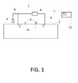
- this shows a schematic block diagram of an arrangement to measure the tightness of a core according to an example of the invention.
- Two accelerometers 6 are arranged at the core 2 which measure an acceleration or vibration caused by the strike of the hammering system 4.
- the acceleration data is transferred to the computer 10 via signal lines or wirelessly.
- the time span between the signals from the both accelerometers 6 is calculated and translated in the computer 10 to the speed of the sound with the known distance ⁇ s of the accelerometers 6 to each other.
- the result of the speed of the corresponding measurement is shown at a display 11 at the computer 10. It was found that the sound speed is a measure for the tightness of the core 2. At investigations it was discovered that a sound wave increases speed when the axial pressure in the core 2 increases.
- the pressure in the core 2 or tightness of the core 2 is deduced from the measured data in the computer 10.
- This data is transferred to the computer 10 and depicted on the display 11.
- the operator of the system or arrangement 1 can decide with the help of the measurement results whether the core 2 can continue operation or needs a repair.
- the software on the computer 10 provides conclusions on basis of the measurement results to support the decision making of the operator.
- the measurement of the sound wave provides a useful indication to the operator regarding the operability of the core 2.
- the measurement is repeated with different positions of the accelerometers 6 at the core 2 to investigate different areas at the core 2.
- a reference pressure is generated by a plier system 8.
- the plier system 8 comprises a hydraulic system to create a substantial pressure to the core 2. This pressure is exerted to the core 2 via two arms 9 at the plier system 8 which reach into gaps of the core 2.
- the gaps can be ventilation ducts of the core 2.
- the arms 9 have an axial distance from each other and span the area of the core 2 which is of interest, at least the area in which the accelerometers 6 are arranged at the core 2.
- the force F or pressure is directed inwardly as indicated by the arrows in Fig. 1 , this means the pressure on the sheets of the core 2 is enhanced by the plier system 8 in a controlled manner.
- the pressure exerted on the core 2 is defined by the plier system 8 and referred to as reference pressure.
- This reference pressure is for example 1MPa.
- a measurement is executed as described under the example above, the measurement data is transferred and stored in the computer 10.
- the reference pressure is applied as described and the measurement of the sound wave is conducted in a similar way.
- the two measurement results are then further calculated, the ratio between the sound speed without a reference pressure and the sound speed with applied reference pressure is calculated in the computer 10.
- the resulting quotient gives an even better understanding of the tightness of the core 2. This is due to the finding that parameters influencing the sound wave speed, like the material, age, or grain orientation, are suppressed. Those parameters being multiple and variable.
Landscapes
- Physics & Mathematics (AREA)
- General Physics & Mathematics (AREA)
- Pathology (AREA)
- Life Sciences & Earth Sciences (AREA)
- Chemical & Material Sciences (AREA)
- Analytical Chemistry (AREA)
- Biochemistry (AREA)
- General Health & Medical Sciences (AREA)
- Immunology (AREA)
- Health & Medical Sciences (AREA)
- Acoustics & Sound (AREA)
- Engineering & Computer Science (AREA)
- Manufacturing & Machinery (AREA)
- Power Engineering (AREA)
- Measurement Of Mechanical Vibrations Or Ultrasonic Waves (AREA)
- Examining Or Testing Airtightness (AREA)
- Force Measurement Appropriate To Specific Purposes (AREA)
- Investigating Or Analyzing Materials By The Use Of Ultrasonic Waves (AREA)
Abstract
Description
- The present disclosure relates to a method and an arrangement for measuring the tightness of a core composed of laminated sheets used in an electric machine.
- The electric machine is in particular a rotating electric machine such as a synchronous generator to be connected to a gas or steam turbine (turbogenerator) or a synchronous generator to be connected to a hydro turbine (hydro generator) or an asynchronous generator or a synchronous or asynchronous electric motor or also other types of electric machines. The electric machine can also be a motor of different kinds. The requirement to the core of the electric machine in the context of this invention is that it is composed of sheets.
- In an electric machine main parts are the rotating rotor and the static stator around the rotor. A key part of the rotor and stator is the core or core package which stator core is composed of stacked and fixed laminated sheets. The highly stressed core is prone to wear which leads to instability over the years of operation. A regular maintenance of the core is necessary thus to assure the stability of the core. The pressure in a stator core is of paramount importance for long and safe machine operations, loose cores generate vibrations leading to stator failures. Several methods and devices are proposed in the state of the art. One method is to arrange a blade or wedge which carries an instrumented tip between the sheets of the core. This method is used to measure the pressure between the core laminations. The reliability of this test method is however in question and only allows the assessment of largely slack cores with highly impaired tightness.
- It is an object of the invention to provide a method and a device for measuring the tightness of a core of an electric machine.
- This object is achieved with a method and an arrangement according to the independent claims.
- Further examples of the invention are disclosed in the dependent claims.
- Advantageously, the core is compressed with a defined reference pressure, the speed of the sound wave in the core is measured, then the pressure from the core is released, and the speed of the sound wave in the core without reference pressure is measured. Afterwards, the ratio between the speed of the sound wave with and without reference pressure is calculated. With these measures the quality of measurement can be improved as several parameters impairing the measurement are suppressed.
- In an example of the invention the reference pressure is applied to the core by a plier system. Such a plier system is suitable to exert a specific pressure to the core in the axial direction. The plier system comprises a hydraulic device and arms to reach between the sheets of the core. For example the arms reach into ventilation ducts of the core.
- In a further example of the invention the sound wave is generated by a hammering system. The hammering system comprises a massive hammer to impose a shock or strike to the core. The strike is done perpendicular to the longitudinal axis of the core but may also be executed in an axial direction of the core. The hammering system is steered and coordinated with the measurement.
- In a further example of the invention the speed of the sound wave in the core is measured by two accelerometers arranged at different positions with a known distance to each other along the axis of the core. The accelerometers are triggered when the vibrations at the core excel a specific value. The time between triggering the two accelerometers is measured and from the known distance the speed of the sound wave is calculated.
- Further characteristics and advantages will be more apparent from the description of a preferred but non-exclusive embodiment of the arrangement and method, illustrated by way of non-limiting example in the accompanying drawings, in which:
- Fig. 1
- shows a schematic block diagram of an arrangement according to an example of the invention with a stator core, a hammering system to pound at the core and produce a sound wave in the core, two accelerometers arranged at the core to measure the sound speed, a plier system to generate a reference pressure in the core via two arms, and a computer to receive and calculate the measured data;
- Fig. 2
- shows an exemplary curve of measured time delays in µs in dependency of different reference pressures applied to the core in MPa.
- With reference to the figure, this shows a schematic block diagram of an arrangement to measure the tightness of a core according to an example of the invention.
-
Fig. 1 shows a schematic block diagram of anarrangement 1 according to an example of the invention. Shown is astator core 2 of an electric machine in a schematic side view which length is in the range of several metres for big machines as turbogenerators. At the left above and adjacent to the core 2 ahammering system 4 is shown. Thehammering system 4 comprises a massive hammer to pound at thecore 2, inFig. 1 from above. The hammer of thehammering system 4 is activated by a signal from adedicated computer 10. This activation signal can be transferred via signal lines or wirelessly. The strike of the hammer on the surface of thecore 2 produces a sound wave which propagates in the material of thecore 2. Twoaccelerometers 6 are arranged at thecore 2 which measure an acceleration or vibration caused by the strike of thehammering system 4. The acceleration data is transferred to thecomputer 10 via signal lines or wirelessly. As oneaccelerometer 6 is more distant to thehammering system 4 than the other the sound wave reaches the moredistant accelerometer 6 later. The time span between the signals from the bothaccelerometers 6 is calculated and translated in thecomputer 10 to the speed of the sound with the known distance δs of theaccelerometers 6 to each other. The result of the speed of the corresponding measurement is shown at adisplay 11 at thecomputer 10. It was found that the sound speed is a measure for the tightness of thecore 2. At investigations it was discovered that a sound wave increases speed when the axial pressure in thecore 2 increases. On basis of this knowledge the pressure in thecore 2 or tightness of thecore 2 is deduced from the measured data in thecomputer 10. This data is transferred to thecomputer 10 and depicted on thedisplay 11. The operator of the system orarrangement 1 can decide with the help of the measurement results whether thecore 2 can continue operation or needs a repair. Alternatively, the software on thecomputer 10 provides conclusions on basis of the measurement results to support the decision making of the operator. In each case the measurement of the sound wave provides a useful indication to the operator regarding the operability of thecore 2. The measurement is repeated with different positions of theaccelerometers 6 at thecore 2 to investigate different areas at thecore 2. By this means deficiencies regarding the tightness of thecore 2 are located precisely. - Above, one example of the invention without applying a pressure to the
core 2 is described. In a further development a reference pressure is generated by aplier system 8. Theplier system 8 comprises a hydraulic system to create a substantial pressure to thecore 2. This pressure is exerted to thecore 2 via twoarms 9 at theplier system 8 which reach into gaps of thecore 2. The gaps can be ventilation ducts of thecore 2. Thearms 9 have an axial distance from each other and span the area of thecore 2 which is of interest, at least the area in which theaccelerometers 6 are arranged at thecore 2. The force F or pressure is directed inwardly as indicated by the arrows inFig. 1 , this means the pressure on the sheets of thecore 2 is enhanced by theplier system 8 in a controlled manner. The pressure exerted on thecore 2 is defined by theplier system 8 and referred to as reference pressure. This reference pressure is for example 1MPa. In this second example first a measurement is executed as described under the example above, the measurement data is transferred and stored in thecomputer 10. Second, the reference pressure is applied as described and the measurement of the sound wave is conducted in a similar way. The two measurement results are then further calculated, the ratio between the sound speed without a reference pressure and the sound speed with applied reference pressure is calculated in thecomputer 10. The resulting quotient gives an even better understanding of the tightness of thecore 2. This is due to the finding that parameters influencing the sound wave speed, like the material, age, or grain orientation, are suppressed. Those parameters being multiple and variable. Calculating the ratio of the measured sound speeds according to this example excludes these influencing quantities. Both examples provide results on which basis a planning of maintenance and repair is done in the contrary to the state of the art. The sound wave measurement allows for a precise determination of the tightness of thecore 2. In the state of the art merely the conclusion is delivered whether to replace defect parts or not. The invention however makes feasible to predict a residual operation time of thecore 2 deduced from the measurement results. From the residual pressure in specific parts of the core 2 a residual operation time of this part of thecore 2 is deduced by the operator or by the software on thecomputer 10. -
Fig. 2 shows an exemplary curve according to the second example of the invention. At the horizontal axis the reference pressure applied to thecore 2 is plotted in MPa. At the vertical axis the measured time delay of the sound wave between the two points defined by thedistant accelerometers 6 in µs is plotted. It can be seen that the curve is strongly changing with the reference pressure. At zero reference pressure a time delay of approximately 190µs is measured, with an applied reference pressure of 1MPa a time delay of approximately 80µs is measured, the sound wave has doubled speed. According to the second example described above the quotient of these two measurement results is calculated in thecomputer 10. The sound wave speed with applied pressure is used as a reference value. From this quotient the tightness of thecore 2 is deduced by tables stored in thecomputer 10. The measurements of the speed of the sound wave can be repeated with any other pressure applied to thecore 2. InFig. 2 five measurements are done with five different core pressures illustrated by five points at the curve. Accordingly, five delay times are measured by theaccelerometers 6. In any case the tightness of thecore 2 is measured at different positions along thecore 2 to obtain a distribution of residual pressure of the sheets along thecore 2. This distribution serves for analysing all parts of thecore 2 in terms of immediate need for maintenance or prediction of a residual operation time of the individual core parts. - While the invention has been described in detail with reference to exemplary embodiments thereof, it will be apparent to one skilled in the art that various changes can be made, and equivalents employed, without departing from the scope of the invention. The foregoing description of the preferred embodiments of the invention has been presented for purposes of illustration and description. It is not intended to be exhaustive or to limit the invention to the precise form disclosed, and modifications and variations are possible in light of the above teachings or may be acquired from practice of the invention. The embodiments were chosen and described in order to explain the principles of the invention and its practical application to enable one skilled in the art to utilize the invention in various embodiments as are suited to the particular use contemplated. It is intended that the scope of the invention be defined by the claims appended hereto, and their equivalents.
-
- 2
- core
- 4
- hammering system
- 6
- accelerometer
- 8
- plier system
- 9
- arm
- 10
- computer
- 11
- display
Claims (7)
- A method for measuring the tightness of a core (2) of an electric machine composed of sheets, with the steps of supplying a sound wave to the core (2), measuring the speed of the sound wave in the core (2), and deducing the tightness of the core (2) from the measured data.
- The method according to claim 1, with the steps of compressing the core (2) with a defined reference pressure, measuring the speed of the sound wave in the core (2) with the reference pressure, releasing the pressure from the core (2), measuring the speed of the sound wave in the core (2) without reference pressure, and calculating the ratio between the speed of the sound wave with and without the reference pressure.
- The method according to claim 2, characterized in that the reference pressure is applied to the core (2) by a plier system (8).
- The method according to claim 1, characterized in that the sound wave is generated by a hammering system (4).
- The method according to claim 1, characterized in that the speed of the sound wave in the core (2) is measured by two accelerometers (6) arranged at different positions along the axis of the core (2).
- Arrangement (1) to measure the tightness of a core of an electric machine (2) composed of sheets, comprising a hammering system (4) to pound at the core (2) for generating a sound wave in the core (2), at least two accelerometers (6) arranged at the core (2) at an axial distance for measuring the speed of the sound wave, and a computer (10) to deduce the tightness of the core (2) from the measured data.
- Arrangement according to claim 6, with a plier system (8) to apply a reference pressure to at least a part of the core (2), and the computer (10) for calculating the ratio between the speed of the sound wave with and without the reference pressure.
Priority Applications (5)
| Application Number | Priority Date | Filing Date | Title |
|---|---|---|---|
| EP15195556.4A EP3171167B1 (en) | 2015-11-20 | 2015-11-20 | A method and arrangement for measuring the tightness of a core in an electric machine |
| PL15195556T PL3171167T3 (en) | 2015-11-20 | 2015-11-20 | A method and arrangement for measuring the tightness of a core in an electric machine |
| US15/352,930 US10352905B2 (en) | 2015-11-20 | 2016-11-16 | Method and arrangement for measuring the tightness of a core in an electric machine |
| CN201611016089.6A CN106885845B (en) | 2015-11-20 | 2016-11-18 | Method and arrangement for measuring the tightness of a magnetic core in an electrical machine |
| RU2016145262A RU2725543C2 (en) | 2015-11-20 | 2016-11-18 | Method and device for measuring degree of compression of core in electrical machine |
Applications Claiming Priority (1)
| Application Number | Priority Date | Filing Date | Title |
|---|---|---|---|
| EP15195556.4A EP3171167B1 (en) | 2015-11-20 | 2015-11-20 | A method and arrangement for measuring the tightness of a core in an electric machine |
Publications (2)
| Publication Number | Publication Date |
|---|---|
| EP3171167A1 true EP3171167A1 (en) | 2017-05-24 |
| EP3171167B1 EP3171167B1 (en) | 2021-08-25 |
Family
ID=54703793
Family Applications (1)
| Application Number | Title | Priority Date | Filing Date |
|---|---|---|---|
| EP15195556.4A Active EP3171167B1 (en) | 2015-11-20 | 2015-11-20 | A method and arrangement for measuring the tightness of a core in an electric machine |
Country Status (5)
| Country | Link |
|---|---|
| US (1) | US10352905B2 (en) |
| EP (1) | EP3171167B1 (en) |
| CN (1) | CN106885845B (en) |
| PL (1) | PL3171167T3 (en) |
| RU (1) | RU2725543C2 (en) |
Citations (2)
| Publication number | Priority date | Publication date | Assignee | Title |
|---|---|---|---|---|
| US3943755A (en) * | 1974-10-22 | 1976-03-16 | Tokyo Shibaura Electric Co., Ltd. | Method and apparatus for measuring the magnitude of a clamping load applied to a laminated iron core of an electric machine |
| RU2223587C2 (en) * | 2000-11-30 | 2004-02-10 | Акционерное общество открытого типа "Электросила" | Method for diagnosing condition of electrical machine stator core |
Family Cites Families (10)
| Publication number | Priority date | Publication date | Assignee | Title |
|---|---|---|---|---|
| JPS5961449A (en) * | 1982-09-30 | 1984-04-07 | Toshiba Corp | Inspecting device for stator of rotary electric machine |
| JPH01218338A (en) * | 1988-02-26 | 1989-08-31 | Hitachi Ltd | Inspecting device for core tightness and method thereof |
| US6424922B1 (en) * | 1998-07-30 | 2002-07-23 | Don E. Bray | Ultrasonic stress measurement using the critically refracted longitudinal (LCR) ultrasonic technique |
| US7360435B2 (en) * | 2004-12-23 | 2008-04-22 | Chrysler Llc | Ultrasonic control of bolt tightening |
| WO2007058196A1 (en) * | 2005-11-16 | 2007-05-24 | Kabushiki Kaisha Toshiba | Stator core loosening diagnosis device and stator core loosening diagnosis method |
| JP2010236892A (en) * | 2009-03-30 | 2010-10-21 | Toshiba Corp | Ultrasonic stress measuring apparatus and ultrasonic stress measuring method |
| EP2383563A1 (en) * | 2010-04-29 | 2011-11-02 | Alstom Technology Ltd | Method and device for testing the tightness of an electric machine stator core |
| CN102156010B (en) * | 2010-12-30 | 2012-11-21 | 首钢总公司 | Internal stress measuring method of opening plate |
| CN102981008B (en) * | 2012-11-14 | 2014-09-10 | 天津大学 | Ultrasonic impact needle speed measurement experiment equipment and application thereof |
| CN104713714B (en) * | 2015-02-09 | 2017-07-28 | 云南电网有限责任公司电力科学研究院 | A kind of primary cut-out action characteristic analysis method clustered based on grid multi-density |
-
2015
- 2015-11-20 PL PL15195556T patent/PL3171167T3/en unknown
- 2015-11-20 EP EP15195556.4A patent/EP3171167B1/en active Active
-
2016
- 2016-11-16 US US15/352,930 patent/US10352905B2/en active Active
- 2016-11-18 CN CN201611016089.6A patent/CN106885845B/en active Active
- 2016-11-18 RU RU2016145262A patent/RU2725543C2/en active
Patent Citations (2)
| Publication number | Priority date | Publication date | Assignee | Title |
|---|---|---|---|---|
| US3943755A (en) * | 1974-10-22 | 1976-03-16 | Tokyo Shibaura Electric Co., Ltd. | Method and apparatus for measuring the magnitude of a clamping load applied to a laminated iron core of an electric machine |
| RU2223587C2 (en) * | 2000-11-30 | 2004-02-10 | Акционерное общество открытого типа "Электросила" | Method for diagnosing condition of electrical machine stator core |
Also Published As
| Publication number | Publication date |
|---|---|
| PL3171167T3 (en) | 2021-12-27 |
| RU2016145262A3 (en) | 2020-02-04 |
| RU2725543C2 (en) | 2020-07-02 |
| RU2016145262A (en) | 2018-05-21 |
| EP3171167B1 (en) | 2021-08-25 |
| CN106885845A (en) | 2017-06-23 |
| US10352905B2 (en) | 2019-07-16 |
| CN106885845B (en) | 2021-02-05 |
| US20170146491A1 (en) | 2017-05-25 |
Similar Documents
| Publication | Publication Date | Title |
|---|---|---|
| US9423330B2 (en) | Method of determining the non-propagation threshold of fatigue cracks at high frequency | |
| RU2551395C2 (en) | Method and device to inspect tightening of electric machine stator core | |
| Booysen et al. | Fatigue life assessment of a low pressure steam turbine blade during transient resonant conditions using a probabilistic approach | |
| JP2017106893A (en) | Method and device for diagnosing abnormality and deterioration in transformer | |
| CN101975701A (en) | Concrete fracture test system and test method thereof | |
| CN103575490B (en) | The loading method of finite space lower support system dynamic flexibility test | |
| CN104792485B (en) | A kind of test method of motor damping characteristic identification | |
| JP2008298527A (en) | Vibration diagnosis method and vibration diagnosis device for rotating machine | |
| CN103954384A (en) | Dynamic stress testing method for stator vane under operating state of gas turbine engine | |
| Bessone et al. | Investigation on the dynamic response of blades with asymmetric under platform dampers | |
| US10020764B2 (en) | System for compensating rotor vibrations | |
| US10352905B2 (en) | Method and arrangement for measuring the tightness of a core in an electric machine | |
| Ortiz et al. | Detection of misalignment in motor via transient current signature analysis | |
| Sz | Failure analysis of steam turbine last stage blade tenon and shroud | |
| Troncossi et al. | Experimental evaluation of the FDS-based equivalence approach for the mission synthesis in accelerated life tests | |
| Abdulraheem et al. | Wind Turbine Blade Fault Detection Using Wavelet Power Spectrum and Experimental Modal Analysis | |
| Kumar et al. | Reinforcement of generator stator end winding structure by modal analysis approach | |
| Dokhe et al. | Effects of crack on modal frequency of cantilever beam | |
| CN206387555U (en) | Traction electric machine stator connection construction vibration experiment | |
| Rajendran et al. | Performance of rotational mode based indices in identification of added mass in beams | |
| Kock et al. | Torque measurement uncertainty in multi-MW nacelle test benches | |
| Sheng et al. | HCF component tests on full-scale low pressure steam turbine end stage blades | |
| Babu et al. | Vibration Analysis of Low Pressure Steam Turbine Blades with Crack | |
| Umezu et al. | Evaluation of on-machine measuring method for dynamic stiffness of thin-walled workpieces | |
| Subbiah | On the determination of bearing support pedestal conditions using shaker testing |
Legal Events
| Date | Code | Title | Description |
|---|---|---|---|
| PUAI | Public reference made under article 153(3) epc to a published international application that has entered the european phase |
Free format text: ORIGINAL CODE: 0009012 |
|
| STAA | Information on the status of an ep patent application or granted ep patent |
Free format text: STATUS: THE APPLICATION HAS BEEN PUBLISHED |
|
| AK | Designated contracting states |
Kind code of ref document: A1 Designated state(s): AL AT BE BG CH CY CZ DE DK EE ES FI FR GB GR HR HU IE IS IT LI LT LU LV MC MK MT NL NO PL PT RO RS SE SI SK SM TR |
|
| AX | Request for extension of the european patent |
Extension state: BA ME |
|
| STAA | Information on the status of an ep patent application or granted ep patent |
Free format text: STATUS: REQUEST FOR EXAMINATION WAS MADE |
|
| 17P | Request for examination filed |
Effective date: 20171124 |
|
| RBV | Designated contracting states (corrected) |
Designated state(s): AL AT BE BG CH CY CZ DE DK EE ES FI FR GB GR HR HU IE IS IT LI LT LU LV MC MK MT NL NO PL PT RO RS SE SI SK SM TR |
|
| GRAP | Despatch of communication of intention to grant a patent |
Free format text: ORIGINAL CODE: EPIDOSNIGR1 |
|
| STAA | Information on the status of an ep patent application or granted ep patent |
Free format text: STATUS: GRANT OF PATENT IS INTENDED |
|
| INTG | Intention to grant announced |
Effective date: 20200930 |
|
| GRAJ | Information related to disapproval of communication of intention to grant by the applicant or resumption of examination proceedings by the epo deleted |
Free format text: ORIGINAL CODE: EPIDOSDIGR1 |
|
| STAA | Information on the status of an ep patent application or granted ep patent |
Free format text: STATUS: REQUEST FOR EXAMINATION WAS MADE |
|
| GRAP | Despatch of communication of intention to grant a patent |
Free format text: ORIGINAL CODE: EPIDOSNIGR1 |
|
| GRAJ | Information related to disapproval of communication of intention to grant by the applicant or resumption of examination proceedings by the epo deleted |
Free format text: ORIGINAL CODE: EPIDOSDIGR1 |
|
| GRAJ | Information related to disapproval of communication of intention to grant by the applicant or resumption of examination proceedings by the epo deleted |
Free format text: ORIGINAL CODE: EPIDOSDIGR1 |
|
| GRAP | Despatch of communication of intention to grant a patent |
Free format text: ORIGINAL CODE: EPIDOSNIGR1 |
|
| STAA | Information on the status of an ep patent application or granted ep patent |
Free format text: STATUS: GRANT OF PATENT IS INTENDED |
|
| GRAP | Despatch of communication of intention to grant a patent |
Free format text: ORIGINAL CODE: EPIDOSNIGR1 |
|
| INTC | Intention to grant announced (deleted) | ||
| GRAJ | Information related to disapproval of communication of intention to grant by the applicant or resumption of examination proceedings by the epo deleted |
Free format text: ORIGINAL CODE: EPIDOSDIGR1 |
|
| GRAP | Despatch of communication of intention to grant a patent |
Free format text: ORIGINAL CODE: EPIDOSNIGR1 |
|
| INTG | Intention to grant announced |
Effective date: 20210303 |
|
| INTC | Intention to grant announced (deleted) | ||
| INTG | Intention to grant announced |
Effective date: 20210317 |
|
| RAP3 | Party data changed (applicant data changed or rights of an application transferred) |
Owner name: GENERAL ELECTRIC TECHNOLOGY GMBH |
|
| INTG | Intention to grant announced |
Effective date: 20210326 |
|
| GRAS | Grant fee paid |
Free format text: ORIGINAL CODE: EPIDOSNIGR3 |
|
| GRAA | (expected) grant |
Free format text: ORIGINAL CODE: 0009210 |
|
| STAA | Information on the status of an ep patent application or granted ep patent |
Free format text: STATUS: THE PATENT HAS BEEN GRANTED |
|
| AK | Designated contracting states |
Kind code of ref document: B1 Designated state(s): AL AT BE BG CH CY CZ DE DK EE ES FI FR GB GR HR HU IE IS IT LI LT LU LV MC MK MT NL NO PL PT RO RS SE SI SK SM TR |
|
| REG | Reference to a national code |
Ref country code: CH Ref legal event code: EP |
|
| REG | Reference to a national code |
Ref country code: IE Ref legal event code: FG4D Ref country code: AT Ref legal event code: REF Ref document number: 1424308 Country of ref document: AT Kind code of ref document: T Effective date: 20210915 |
|
| REG | Reference to a national code |
Ref country code: DE Ref legal event code: R096 Ref document number: 602015072557 Country of ref document: DE |
|
| REG | Reference to a national code |
Ref country code: LT Ref legal event code: MG9D |
|
| REG | Reference to a national code |
Ref country code: NL Ref legal event code: MP Effective date: 20210825 |
|
| REG | Reference to a national code |
Ref country code: AT Ref legal event code: MK05 Ref document number: 1424308 Country of ref document: AT Kind code of ref document: T Effective date: 20210825 |
|
| PG25 | Lapsed in a contracting state [announced via postgrant information from national office to epo] |
Ref country code: HR Free format text: LAPSE BECAUSE OF FAILURE TO SUBMIT A TRANSLATION OF THE DESCRIPTION OR TO PAY THE FEE WITHIN THE PRESCRIBED TIME-LIMIT Effective date: 20210825 Ref country code: SE Free format text: LAPSE BECAUSE OF FAILURE TO SUBMIT A TRANSLATION OF THE DESCRIPTION OR TO PAY THE FEE WITHIN THE PRESCRIBED TIME-LIMIT Effective date: 20210825 Ref country code: RS Free format text: LAPSE BECAUSE OF FAILURE TO SUBMIT A TRANSLATION OF THE DESCRIPTION OR TO PAY THE FEE WITHIN THE PRESCRIBED TIME-LIMIT Effective date: 20210825 Ref country code: LT Free format text: LAPSE BECAUSE OF FAILURE TO SUBMIT A TRANSLATION OF THE DESCRIPTION OR TO PAY THE FEE WITHIN THE PRESCRIBED TIME-LIMIT Effective date: 20210825 Ref country code: BG Free format text: LAPSE BECAUSE OF FAILURE TO SUBMIT A TRANSLATION OF THE DESCRIPTION OR TO PAY THE FEE WITHIN THE PRESCRIBED TIME-LIMIT Effective date: 20211125 Ref country code: AT Free format text: LAPSE BECAUSE OF FAILURE TO SUBMIT A TRANSLATION OF THE DESCRIPTION OR TO PAY THE FEE WITHIN THE PRESCRIBED TIME-LIMIT Effective date: 20210825 Ref country code: PT Free format text: LAPSE BECAUSE OF FAILURE TO SUBMIT A TRANSLATION OF THE DESCRIPTION OR TO PAY THE FEE WITHIN THE PRESCRIBED TIME-LIMIT Effective date: 20211227 Ref country code: NO Free format text: LAPSE BECAUSE OF FAILURE TO SUBMIT A TRANSLATION OF THE DESCRIPTION OR TO PAY THE FEE WITHIN THE PRESCRIBED TIME-LIMIT Effective date: 20211125 Ref country code: ES Free format text: LAPSE BECAUSE OF FAILURE TO SUBMIT A TRANSLATION OF THE DESCRIPTION OR TO PAY THE FEE WITHIN THE PRESCRIBED TIME-LIMIT Effective date: 20210825 Ref country code: FI Free format text: LAPSE BECAUSE OF FAILURE TO SUBMIT A TRANSLATION OF THE DESCRIPTION OR TO PAY THE FEE WITHIN THE PRESCRIBED TIME-LIMIT Effective date: 20210825 |
|
| PG25 | Lapsed in a contracting state [announced via postgrant information from national office to epo] |
Ref country code: LV Free format text: LAPSE BECAUSE OF FAILURE TO SUBMIT A TRANSLATION OF THE DESCRIPTION OR TO PAY THE FEE WITHIN THE PRESCRIBED TIME-LIMIT Effective date: 20210825 Ref country code: GR Free format text: LAPSE BECAUSE OF FAILURE TO SUBMIT A TRANSLATION OF THE DESCRIPTION OR TO PAY THE FEE WITHIN THE PRESCRIBED TIME-LIMIT Effective date: 20211126 |
|
| PG25 | Lapsed in a contracting state [announced via postgrant information from national office to epo] |
Ref country code: NL Free format text: LAPSE BECAUSE OF FAILURE TO SUBMIT A TRANSLATION OF THE DESCRIPTION OR TO PAY THE FEE WITHIN THE PRESCRIBED TIME-LIMIT Effective date: 20210825 |
|
| PG25 | Lapsed in a contracting state [announced via postgrant information from national office to epo] |
Ref country code: DK Free format text: LAPSE BECAUSE OF FAILURE TO SUBMIT A TRANSLATION OF THE DESCRIPTION OR TO PAY THE FEE WITHIN THE PRESCRIBED TIME-LIMIT Effective date: 20210825 |
|
| REG | Reference to a national code |
Ref country code: DE Ref legal event code: R097 Ref document number: 602015072557 Country of ref document: DE |
|
| PG25 | Lapsed in a contracting state [announced via postgrant information from national office to epo] |
Ref country code: SM Free format text: LAPSE BECAUSE OF FAILURE TO SUBMIT A TRANSLATION OF THE DESCRIPTION OR TO PAY THE FEE WITHIN THE PRESCRIBED TIME-LIMIT Effective date: 20210825 Ref country code: SK Free format text: LAPSE BECAUSE OF FAILURE TO SUBMIT A TRANSLATION OF THE DESCRIPTION OR TO PAY THE FEE WITHIN THE PRESCRIBED TIME-LIMIT Effective date: 20210825 Ref country code: RO Free format text: LAPSE BECAUSE OF FAILURE TO SUBMIT A TRANSLATION OF THE DESCRIPTION OR TO PAY THE FEE WITHIN THE PRESCRIBED TIME-LIMIT Effective date: 20210825 Ref country code: EE Free format text: LAPSE BECAUSE OF FAILURE TO SUBMIT A TRANSLATION OF THE DESCRIPTION OR TO PAY THE FEE WITHIN THE PRESCRIBED TIME-LIMIT Effective date: 20210825 Ref country code: CZ Free format text: LAPSE BECAUSE OF FAILURE TO SUBMIT A TRANSLATION OF THE DESCRIPTION OR TO PAY THE FEE WITHIN THE PRESCRIBED TIME-LIMIT Effective date: 20210825 Ref country code: AL Free format text: LAPSE BECAUSE OF FAILURE TO SUBMIT A TRANSLATION OF THE DESCRIPTION OR TO PAY THE FEE WITHIN THE PRESCRIBED TIME-LIMIT Effective date: 20210825 |
|
| PG25 | Lapsed in a contracting state [announced via postgrant information from national office to epo] |
Ref country code: MC Free format text: LAPSE BECAUSE OF FAILURE TO SUBMIT A TRANSLATION OF THE DESCRIPTION OR TO PAY THE FEE WITHIN THE PRESCRIBED TIME-LIMIT Effective date: 20210825 |
|
| REG | Reference to a national code |
Ref country code: CH Ref legal event code: PL |
|
| PLBE | No opposition filed within time limit |
Free format text: ORIGINAL CODE: 0009261 |
|
| STAA | Information on the status of an ep patent application or granted ep patent |
Free format text: STATUS: NO OPPOSITION FILED WITHIN TIME LIMIT |
|
| PG25 | Lapsed in a contracting state [announced via postgrant information from national office to epo] |
Ref country code: LU Free format text: LAPSE BECAUSE OF NON-PAYMENT OF DUE FEES Effective date: 20211120 Ref country code: BE Free format text: LAPSE BECAUSE OF NON-PAYMENT OF DUE FEES Effective date: 20211130 |
|
| REG | Reference to a national code |
Ref country code: BE Ref legal event code: MM Effective date: 20211130 |
|
| 26N | No opposition filed |
Effective date: 20220527 |
|
| PG25 | Lapsed in a contracting state [announced via postgrant information from national office to epo] |
Ref country code: SI Free format text: LAPSE BECAUSE OF FAILURE TO SUBMIT A TRANSLATION OF THE DESCRIPTION OR TO PAY THE FEE WITHIN THE PRESCRIBED TIME-LIMIT Effective date: 20210825 Ref country code: LI Free format text: LAPSE BECAUSE OF NON-PAYMENT OF DUE FEES Effective date: 20211130 Ref country code: CH Free format text: LAPSE BECAUSE OF NON-PAYMENT OF DUE FEES Effective date: 20211130 |
|
| PG25 | Lapsed in a contracting state [announced via postgrant information from national office to epo] |
Ref country code: IE Free format text: LAPSE BECAUSE OF NON-PAYMENT OF DUE FEES Effective date: 20211120 |
|
| PG25 | Lapsed in a contracting state [announced via postgrant information from national office to epo] |
Ref country code: HU Free format text: LAPSE BECAUSE OF FAILURE TO SUBMIT A TRANSLATION OF THE DESCRIPTION OR TO PAY THE FEE WITHIN THE PRESCRIBED TIME-LIMIT; INVALID AB INITIO Effective date: 20151120 |
|
| P01 | Opt-out of the competence of the unified patent court (upc) registered |
Effective date: 20230523 |
|
| PG25 | Lapsed in a contracting state [announced via postgrant information from national office to epo] |
Ref country code: CY Free format text: LAPSE BECAUSE OF FAILURE TO SUBMIT A TRANSLATION OF THE DESCRIPTION OR TO PAY THE FEE WITHIN THE PRESCRIBED TIME-LIMIT Effective date: 20210825 |
|
| PG25 | Lapsed in a contracting state [announced via postgrant information from national office to epo] |
Ref country code: MK Free format text: LAPSE BECAUSE OF FAILURE TO SUBMIT A TRANSLATION OF THE DESCRIPTION OR TO PAY THE FEE WITHIN THE PRESCRIBED TIME-LIMIT Effective date: 20210825 |
|
| PG25 | Lapsed in a contracting state [announced via postgrant information from national office to epo] |
Ref country code: TR Free format text: LAPSE BECAUSE OF FAILURE TO SUBMIT A TRANSLATION OF THE DESCRIPTION OR TO PAY THE FEE WITHIN THE PRESCRIBED TIME-LIMIT Effective date: 20210825 |
|
| PG25 | Lapsed in a contracting state [announced via postgrant information from national office to epo] |
Ref country code: MT Free format text: LAPSE BECAUSE OF FAILURE TO SUBMIT A TRANSLATION OF THE DESCRIPTION OR TO PAY THE FEE WITHIN THE PRESCRIBED TIME-LIMIT Effective date: 20210825 |
|
| REG | Reference to a national code |
Ref country code: DE Ref legal event code: R081 Ref document number: 602015072557 Country of ref document: DE Owner name: ARABELLE SOLUTIONS FRANCE, FR Free format text: FORMER OWNER: GENERAL ELECTRIC TECHNOLOGY GMBH, BADEN, CH Ref country code: DE Ref legal event code: R081 Ref document number: 602015072557 Country of ref document: DE Owner name: ARABELLE TECHNOLOGIES, FR Free format text: FORMER OWNER: GENERAL ELECTRIC TECHNOLOGY GMBH, BADEN, CH |
|
| REG | Reference to a national code |
Ref country code: GB Ref legal event code: 732E Free format text: REGISTERED BETWEEN 20250213 AND 20250219 |
|
| REG | Reference to a national code |
Ref country code: DE Ref legal event code: R081 Ref document number: 602015072557 Country of ref document: DE Owner name: ARABELLE SOLUTIONS FRANCE, FR Free format text: FORMER OWNER: ARABELLE TECHNOLOGIES, BOULOGNE-BILLANCOURT, FR |
|
| REG | Reference to a national code |
Ref country code: GB Ref legal event code: 732E Free format text: REGISTERED BETWEEN 20250619 AND 20250625 |
|
| PGFP | Annual fee paid to national office [announced via postgrant information from national office to epo] |
Ref country code: DE Payment date: 20251022 Year of fee payment: 11 |
|
| PGFP | Annual fee paid to national office [announced via postgrant information from national office to epo] |
Ref country code: GB Payment date: 20251023 Year of fee payment: 11 |
|
| PGFP | Annual fee paid to national office [announced via postgrant information from national office to epo] |
Ref country code: IT Payment date: 20251022 Year of fee payment: 11 |
|
| PGFP | Annual fee paid to national office [announced via postgrant information from national office to epo] |
Ref country code: FR Payment date: 20251023 Year of fee payment: 11 |
|
| PGFP | Annual fee paid to national office [announced via postgrant information from national office to epo] |
Ref country code: PL Payment date: 20251023 Year of fee payment: 11 |