EP3171079A1 - Adapter for a luminaire controller - Google Patents
Adapter for a luminaire controller Download PDFInfo
- Publication number
- EP3171079A1 EP3171079A1 EP16198883.7A EP16198883A EP3171079A1 EP 3171079 A1 EP3171079 A1 EP 3171079A1 EP 16198883 A EP16198883 A EP 16198883A EP 3171079 A1 EP3171079 A1 EP 3171079A1
- Authority
- EP
- European Patent Office
- Prior art keywords
- lighting controller
- port
- luminaire
- adapter
- receptacle
- Prior art date
- Legal status (The legal status is an assumption and is not a legal conclusion. Google has not performed a legal analysis and makes no representation as to the accuracy of the status listed.)
- Withdrawn
Links
- 238000000034 method Methods 0.000 claims abstract description 33
- 238000012423 maintenance Methods 0.000 claims abstract description 16
- 230000004888 barrier function Effects 0.000 claims description 18
- 230000006870 function Effects 0.000 description 21
- 238000011161 development Methods 0.000 description 10
- 238000004891 communication Methods 0.000 description 4
- 238000012986 modification Methods 0.000 description 3
- 230000004048 modification Effects 0.000 description 3
- 238000012545 processing Methods 0.000 description 3
- 238000010586 diagram Methods 0.000 description 2
- 239000011521 glass Substances 0.000 description 2
- 238000005259 measurement Methods 0.000 description 2
- 230000006978 adaptation Effects 0.000 description 1
- 239000000470 constituent Substances 0.000 description 1
- 238000013500 data storage Methods 0.000 description 1
- WABPQHHGFIMREM-AKLPVKDBSA-N lead-210 Chemical compound [210Pb] WABPQHHGFIMREM-AKLPVKDBSA-N 0.000 description 1
- 230000003287 optical effect Effects 0.000 description 1
- 230000002093 peripheral effect Effects 0.000 description 1
- 230000008569 process Effects 0.000 description 1
- 239000004065 semiconductor Substances 0.000 description 1
- 230000011664 signaling Effects 0.000 description 1
- 238000012360 testing method Methods 0.000 description 1
Images


Classifications
-
- F—MECHANICAL ENGINEERING; LIGHTING; HEATING; WEAPONS; BLASTING
- F21—LIGHTING
- F21V—FUNCTIONAL FEATURES OR DETAILS OF LIGHTING DEVICES OR SYSTEMS THEREOF; STRUCTURAL COMBINATIONS OF LIGHTING DEVICES WITH OTHER ARTICLES, NOT OTHERWISE PROVIDED FOR
- F21V23/00—Arrangement of electric circuit elements in or on lighting devices
- F21V23/003—Arrangement of electric circuit elements in or on lighting devices the elements being electronics drivers or controllers for operating the light source, e.g. for a LED array
-
- H—ELECTRICITY
- H05—ELECTRIC TECHNIQUES NOT OTHERWISE PROVIDED FOR
- H05B—ELECTRIC HEATING; ELECTRIC LIGHT SOURCES NOT OTHERWISE PROVIDED FOR; CIRCUIT ARRANGEMENTS FOR ELECTRIC LIGHT SOURCES, IN GENERAL
- H05B45/00—Circuit arrangements for operating light-emitting diodes [LED]
- H05B45/10—Controlling the intensity of the light
-
- F—MECHANICAL ENGINEERING; LIGHTING; HEATING; WEAPONS; BLASTING
- F21—LIGHTING
- F21V—FUNCTIONAL FEATURES OR DETAILS OF LIGHTING DEVICES OR SYSTEMS THEREOF; STRUCTURAL COMBINATIONS OF LIGHTING DEVICES WITH OTHER ARTICLES, NOT OTHERWISE PROVIDED FOR
- F21V23/00—Arrangement of electric circuit elements in or on lighting devices
- F21V23/003—Arrangement of electric circuit elements in or on lighting devices the elements being electronics drivers or controllers for operating the light source, e.g. for a LED array
- F21V23/007—Arrangement of electric circuit elements in or on lighting devices the elements being electronics drivers or controllers for operating the light source, e.g. for a LED array enclosed in a casing
- F21V23/008—Arrangement of electric circuit elements in or on lighting devices the elements being electronics drivers or controllers for operating the light source, e.g. for a LED array enclosed in a casing the casing being outside the housing of the lighting device
-
- F—MECHANICAL ENGINEERING; LIGHTING; HEATING; WEAPONS; BLASTING
- F21—LIGHTING
- F21V—FUNCTIONAL FEATURES OR DETAILS OF LIGHTING DEVICES OR SYSTEMS THEREOF; STRUCTURAL COMBINATIONS OF LIGHTING DEVICES WITH OTHER ARTICLES, NOT OTHERWISE PROVIDED FOR
- F21V23/00—Arrangement of electric circuit elements in or on lighting devices
- F21V23/06—Arrangement of electric circuit elements in or on lighting devices the elements being coupling devices, e.g. connectors
-
- H—ELECTRICITY
- H01—ELECTRIC ELEMENTS
- H01R—ELECTRICALLY-CONDUCTIVE CONNECTIONS; STRUCTURAL ASSOCIATIONS OF A PLURALITY OF MUTUALLY-INSULATED ELECTRICAL CONNECTING ELEMENTS; COUPLING DEVICES; CURRENT COLLECTORS
- H01R33/00—Coupling devices specially adapted for supporting apparatus and having one part acting as a holder providing support and electrical connection via a counterpart which is structurally associated with the apparatus, e.g. lamp holders; Separate parts thereof
- H01R33/74—Devices having four or more poles, e.g. holders for compact fluorescent lamps
- H01R33/76—Holders with sockets, clips, or analogous contacts adapted for axially-sliding engagement with parallely-arranged pins, blades, or analogous contacts on counterpart, e.g. electronic tube socket
- H01R33/7607—Holders with sockets, clips, or analogous contacts adapted for axially-sliding engagement with parallely-arranged pins, blades, or analogous contacts on counterpart, e.g. electronic tube socket the parallel terminal pins having a circular disposition
-
- H—ELECTRICITY
- H05—ELECTRIC TECHNIQUES NOT OTHERWISE PROVIDED FOR
- H05B—ELECTRIC HEATING; ELECTRIC LIGHT SOURCES NOT OTHERWISE PROVIDED FOR; CIRCUIT ARRANGEMENTS FOR ELECTRIC LIGHT SOURCES, IN GENERAL
- H05B47/00—Circuit arrangements for operating light sources in general, i.e. where the type of light source is not relevant
- H05B47/10—Controlling the light source
- H05B47/175—Controlling the light source by remote control
- H05B47/18—Controlling the light source by remote control via data-bus transmission
-
- F—MECHANICAL ENGINEERING; LIGHTING; HEATING; WEAPONS; BLASTING
- F21—LIGHTING
- F21W—INDEXING SCHEME ASSOCIATED WITH SUBCLASSES F21K, F21L, F21S and F21V, RELATING TO USES OR APPLICATIONS OF LIGHTING DEVICES OR SYSTEMS
- F21W2131/00—Use or application of lighting devices or systems not provided for in codes F21W2102/00-F21W2121/00
- F21W2131/10—Outdoor lighting
- F21W2131/103—Outdoor lighting of streets or roads
-
- F—MECHANICAL ENGINEERING; LIGHTING; HEATING; WEAPONS; BLASTING
- F21—LIGHTING
- F21Y—INDEXING SCHEME ASSOCIATED WITH SUBCLASSES F21K, F21L, F21S and F21V, RELATING TO THE FORM OR THE KIND OF THE LIGHT SOURCES OR OF THE COLOUR OF THE LIGHT EMITTED
- F21Y2115/00—Light-generating elements of semiconductor light sources
- F21Y2115/10—Light-emitting diodes [LED]
Definitions
- the present disclosure generally relates to luminaires. More particularly, the present disclosure relates to an adapter for performing various functions associated with a luminaire controller.
- Calibration, maintenance, and development functions in luminaires are typically achieved using a combination of interfaces.
- These interfaces can include, for example, ANSI C136.41 receptacle pins and header pins disposed on the lighting controller itself.
- maintenance, calibration, and development can typically be performed solely through the ANSI C136.41 pins, albeit without a single adapter that can interface with the controller. Accordingly, there is a need for lighting control maintenance, calibration, and development procedures that are much simpler; in other words, there is a need for hardware that reduce the number of interfaces needed to perform at least the aforementioned functions.
- the embodiments featured herein help solve or mitigate the above-noted issues as well as other issues known in the art.
- the embodiments enable all calibration and maintenance functions to be performed through a lighting controller receptacle's pins.
- the embodiments include all of the peripherals necessary to achieve calibration or maintenance functions through the receptacle pins, especially when the receptacle is implemented according to the ANSI C136.41 standard.
- an adapter for use with a lighting controller of a luminaire.
- the adapter includes a WECO port that is designed by default to be connected to a metering circuit disposed in the lighting controller.
- the adapter includes an interface connected to the lighting controller, to at least one lead of a lighting controller receptacle of the luminaire, and to at least one port of a computing device.
- a method for use with a luminaire includes interfacing a processor with the lighting control receptacle of the luminaire.
- the method further includes controlling, by the processor, parameters of the luminaire via an interface connected to the processor and to at least one lead of a lighting controller receptacle of the luminaire.
- the method can include performing, via a WECO port communicatively coupled to the processor and by the processor, one of a calibration function associated with the luminaire and a maintenance function associated with the luminaire.
- an adapter for use with a lighting controller of a luminaire.
- the adapter includes a first port connected to a metering circuit disposed in the lighting controller.
- the adapter further includes a second port connected to a processor of the lighting controller.
- the adapter can include an interface that comprises the first port and the second port. The interface can be communicatively coupled to at least one lead of a lighting controller receptacle of the luminaire.
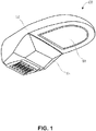
- FIG. 1 is an illustration of a luminaire 100 in which embodiments of the invention may be practiced.
- Luminaire 100 includes a dorsal portion 102 on to which is mounted a light receptor receptacle (not shown).
- Luminaire 100 further includes a cavity in which are placed light sources, such as light emitting diodes, for example.
- the cavity may be covered with a transparent glass 104 that serves to protect the light sources from the elements.
- glass 104 may also function as a lens.
- Luminaire 100 can further include a section 106 that is reserved for a wide variety of additional components.
- section 106 may transparent and include cameras.
- section 106 can include global positioning system (GPS) hardware.
- GPS global positioning system
- FIG. 2 is a top view 200 of luminaire 100.
- top view 200 shows a lighting controller receptacle 204 disposed on the dorsal portion 202 of luminaire 100.
- Lighting controller receptacle 204 protrudes outward from the surface of dorsal portion 202 and it extend inward within the body of luminaire 100.
- a plurality of leads are disposed on the inner side of lighting controller receptacle 204, i.e. the portion extending inward within the body of luminaire 100.
- lighting controller receptacle 204 includes a plurality of pins, which are pin 206, pin 208, pin 212 , pin 210, pin 214, pin 216, and pin 218. Each of these pins is associated with one lead (not shown). Without loss of generality, hereinafter, a lead will be referred to with the numeral corresponding to the pin to which it is attached. For example, lead 210 will refer to the lead being attached to pin 210 on the inner side of the lighting controller receptacle 204.
- Embodiments of the invention may include any controllers that interface through the standard lighting control receptacle of a luminaire, such as lighting controller receptacle 204.
- lighting controller receptacle 204 may be defined using the ANSI C136.41 standard. That is, lighting controller receptacle 204 may have a 7-pin interface as shown in Figure 2 . Of the seven pins, three pins (212, 214, and 216) may be dedicated to providing power to a controller mounted on lighting controller receptacle 204. The remaining four pins may be dedicated to low-voltage signaling and control.
- pin 206 and pin 210 may be dedicated to 0-10V dimming and/or Digital Addressable Lighting Interface TM (DALI TM), and pins 208 and 206 may be unassigned, i.e. they may be left for the manufacturer to define.
- DALI TM Digital Addressable Lighting Interface
- Figure 3 is an illustration of a perspective view 300 of lighting controller receptacle 302.
- Outer side 314 corresponds to the portion of lighting controller receptacle 302 that is outside luminaire 100, i.e. the portion that protrudes outward from dorsal portion 102 of luminaire 100.
- inner side 312 corresponds to the portion of lighting controller receptacle 302 that extends within luminaire 100.
- Leads 304, 306, 308, 310 correspond to pins 304, 306, 308, and 310, respectively.
- Figure 4 shows a block diagram of a device 400.
- Device 400 can include a bus 420 adapted to interface with lighting controller receptacle 202 or 302.
- bus 420 can have a connector that is designed to mate with lighting controller receptacle 202, in order to provide an interface between controller 400 and the components of luminaire 100.
- Device 400 is a programmable device, or it may be a programmable module located in a much larger device.
- device 400 can be part of a node mounted on lighting controller receptacle 202, the node having a plurality of functionalities.
- the node may include a photo-electric element configured to sense ambient light and provide dimming commands to the luminaire, based on predetermined ambient light level thresholds.
- the node may include wireless communication hardware, or communication hardware that use power line communication protocols.
- the node can include hardware for controlling one or more cameras located in luminaire 100, in addition to hardware capable of processing and transmitting data from the one or more cameras.
- One of skill in the art will readily recognize that such a node may have additional functionalities/hardware beyond those described herein.
- Device 400 may include one or more hardware and/or software components configured to fetch, decode, execute, store, analyze, distribute, evaluate, and/or categorize information. Furthermore, device 400 may be battery-powered or it may include a power supply specifically suited for drawing power from a powerline or from a power supply of luminaire 100.
- Device 400 can further include an interface 416, which may be a single adapter that encapsulates ports for all calibration, maintenance, and development functionality.
- the lighting controller receptacle 204 or 302 may be implemented using a 7-pin ANSI C136.41 configuration.
- interface 416 i.e. the single adapter, provides the capability to achieve all calibration, maintenance, and development functionalities through the 7-pin ANSI C136.41 configuration via interface 416 through bus 420.
- Device 400 can include one or more processors like processor 412, a storage device 408, a memory 402 or the like, and input/output hardware (I/O module 414) configured to interface with bus 420 and lighting controller receptacle 202 (not shown in Figure 4 ).
- processors like processor 412
- storage device 408 a memory 402 or the like
- I/O module 414 input/output hardware
- Processor 412 may include one or more processing devices or cores (not shown). In some embodiments, processor 412 may be a plurality of processors, each having either one or more cores. Processor 412 can be configured for execution of instructions fetched from memory 402, for example from one of memory block 404, memory block 406, memory block 408, or memory block 410, or the instructions may be fetched from storage device 408, or from a remote device connected via interface 416.
- storage device 418 and/or memory 402 may include a volatile or non-volatile, magnetic, semiconductor, tape, optical, removable, non-removable, read-only, random-access, or other type of storage device or non-transitory computer-readable computer medium.
- Storage device 418 and/or memory 402 may include programs and/or other information that may be used by processor 412.
- Storage device 418 may be configured to log data processed, recorded, or collected during the operation of device 400.
- the data may be time-stamped, GPS-tagged, cataloged, indexed, or organized in a variety of ways consistent with data storage practice, and this without departing from the scope of the present disclosure.
- device 400 The functionality of device 400 is imparted by its structure. Namely, the structure of device 400 is provided by the software or firmware contained in a plurality of memory sectors of memory 402, of which only memory block 404, memory block 406, memory block 408, and memory block 410 are shown for clarity.
- memory block 404 may include instructions that, when executed by processor 410, cause processor 410 to calibrate one or more circuits or circuit parameters (e.g. driver current, operating voltage, etc.) in luminaire 100.
- Calibration may entail setting a driver current set point, or it may entail setting up a look up table correlating values of current measurements with lumen output.
- memory block 408 can include instructions that cause processor 412 to program ON and OFF schedules for the luminaire, or development functions.
- Development functions may include programming the electrical parameters of the luminaire 100, or loading programs into memory 402 for use by device 100 once luminaire 100 is deployed, with the device 400 mounted therein.
- All instructions for performing calibration, maintenance, or development functions can be loaded via a single interface 416, which can include WECO and USB ports, in addition to a barrier block that provides the single interface.
- the WECO port may comprise a port manufactured or sold under the "WECO" brand name (e.g., by WECO Electrical Connectors Inc.), or a port that is manufactured or sold under some other brand name but that conforms to the electrical and/or mechanical configuration of a WECOTM brand port.
- the interface can be a port to any suitable meter testing device.
- the ANSI C136.41 is disclosed herein as an exemplary implementation for lighting controller receptacle 202 or 302, the invention is not limited to luminaires that include receptacles implemented according to that standard. Rather, the invention may be practiced with any luminaire, and other standards may be used, so long as a single interface is provided for performing the disparate set of functions (e.g. calibration, maintenance, and development) via the receptacle.
- device 400 can include an interface 416 that is connected directly to bus 420 and metering circuit 422.
- all memory and processing functions can simply be implemented using a computing device that is connected to interface 416 via the single interface, the interface 416 being configured to support WECO and USB protocols, for example.
- device 400 may include a metering circuit 522, which may be programmed to measure and/or estimate any electrical parameters associated with the power consumption by the luminaire. Such measures or estimates may include current, voltage, power dissipation, power factor, phasor data, and like measurements.
- FIG 5 is an illustration of interface 416, according to an embodiment.
- Interface 416 can include a barrier block 502 that provides connections to a plurality of connectors, each supporting a distinct communication protocol.
- barrier block 502 provides a connection to a first port 508, which can be configured to support a first protocol.
- first port 508 may be a WECO port, and it may support connections to meter reading equipment that can be used to read data from metering circuit 422 (see Figure 4 ).
- Second port 510 can be a USB port configured to allow a developer to program device 400 to perform specific tasks, such as loading/reading calibration data, performing maintenance functions, etc.
- signals originating from the two unassigned leads of the lighting controller receptacle 204 or 302 may be routed via receptacle pins 504 to pins 8 and 10 of barrier block 502. These signals may be converted to a proper format for outputting via second port 510.
- the formatting may include serializing the data originating from pins 8 and 10 of barrier block 502.
- Barrier block 502 further provides a connection to the lighting controller receptacle 204 or 302, via receptacle pins 504 (for example).
- receptacle pins 504 for example.
- barrier block 502 may be implemented to provide connections to all the pins of lighting controller receptacle 204 or 302.
- the lighting controller receptacle 204 may be implemented according to the ANSI C136.41 standard.
- Method 600 can include interfacing a processor with the lighting control receptacle of the luminaire (step 502).
- the processor can be like the one described in the context of Figure 4 .
- step 602 can include interfacing an entire controller like device 400 with lighting controller receptacle 302.
- Method 600 can include a step 604 that includes controlling, by the processor, electrical parameters of the luminaire via an interface connected to the processor and to at least one lead of a lighting controller receptacle of the luminaire.
- the parameters may be such as the ones previously described.
- method 600 can include a step 606, wherein the processor performs, via a WECO port communicatively coupled to the processor, one of a calibration function associated with the luminaire and a maintenance function associated with the luminaire. Such functions may be like the ones described above. In one embodiment, method 600 may end at step 608.
- method 600 may further include interfacing the processor with seven leads included in the lighting controller receptacle.
- the receptacle is implemented according to the ANSI C136.41 standard, and method 600 may further include interfacing the processor with at least one lead of the lighting controller receptacle.
- method 600 may further include interfacing the processor with all the leads of the receptacle. Furthermore, method 600 may further include communicating with the processor via a USB port.
Landscapes
- Engineering & Computer Science (AREA)
- General Engineering & Computer Science (AREA)
- Microelectronics & Electronic Packaging (AREA)
- Circuit Arrangement For Electric Light Sources In General (AREA)
- Arrangement Of Elements, Cooling, Sealing, Or The Like Of Lighting Devices (AREA)
Abstract
Description
- The present disclosure generally relates to luminaires. More particularly, the present disclosure relates to an adapter for performing various functions associated with a luminaire controller.
- Calibration, maintenance, and development functions in luminaires are typically achieved using a combination of interfaces. These interfaces can include, for example, ANSI C136.41 receptacle pins and header pins disposed on the lighting controller itself. Alternatively, maintenance, calibration, and development can typically be performed solely through the ANSI C136.41 pins, albeit without a single adapter that can interface with the controller. Accordingly, there is a need for lighting control maintenance, calibration, and development procedures that are much simpler; in other words, there is a need for hardware that reduce the number of interfaces needed to perform at least the aforementioned functions.
- The embodiments featured herein help solve or mitigate the above-noted issues as well as other issues known in the art. Specifically, the embodiments enable all calibration and maintenance functions to be performed through a lighting controller receptacle's pins. The embodiments include all of the peripherals necessary to achieve calibration or maintenance functions through the receptacle pins, especially when the receptacle is implemented according to the ANSI C136.41 standard.
- For example, in one embodiment, there is provided an adapter for use with a lighting controller of a luminaire. The adapter includes a WECO port that is designed by default to be connected to a metering circuit disposed in the lighting controller. Furthermore, the adapter includes an interface connected to the lighting controller, to at least one lead of a lighting controller receptacle of the luminaire, and to at least one port of a computing device.
- In another exemplary embodiment, there is provided a method for use with a luminaire. The method includes interfacing a processor with the lighting control receptacle of the luminaire. The method further includes controlling, by the processor, parameters of the luminaire via an interface connected to the processor and to at least one lead of a lighting controller receptacle of the luminaire. Furthermore, the method can include performing, via a WECO port communicatively coupled to the processor and by the processor, one of a calibration function associated with the luminaire and a maintenance function associated with the luminaire.
- In yet another exemplary embodiment, there is provided an adapter for use with a lighting controller of a luminaire. The adapter includes a first port connected to a metering circuit disposed in the lighting controller. The adapter further includes a second port connected to a processor of the lighting controller. Furthermore the adapter can include an interface that comprises the first port and the second port. The interface can be communicatively coupled to at least one lead of a lighting controller receptacle of the luminaire.
- Additional features, modes of operations, advantages, and other aspects of various embodiments are described below with reference to the accompanying drawings. It is noted that the present disclosure is not limited to the specific embodiments described herein. These embodiments are presented for illustrative purposes only. Additional embodiments, or modifications of the embodiments disclosed, will be readily apparent to persons skilled in the relevant art(s) based on the teachings provided.
- Illustrative embodiments may take form in various components and arrangements of components. Illustrative embodiments are shown in the accompanying drawings, throughout which like reference numerals may indicate corresponding or similar parts in the various drawings. The drawings are only for purposes of illustrating the embodiments and are not to be construed as limiting the disclosure. Given the following enabling description of the drawings, the novel aspects of the present disclosure should become evident to a person of ordinary skill in the relevant art(s).
-
FIG. 1 is an illustration of a luminaire in which embodiments of the invention may be practiced. -
FIG. 2 is a top view of the luminaire ofFigure 1 , according to an embodiment. -
FIG. 3 is an illustration of a light lighting controller receptacle, according to an embodiment. -
FIG. 4 is an illustration of a block diagram of a device, according to an embodiment. -
FIG. 5 is an illustration of an interface, according to an embodiment. -
FIG. 6 illustrates a method, according to an embodiment. - While the illustrative embodiments are described herein for particular applications, it should be understood that the present disclosure is not limited thereto. Those skilled in the art and with access to the teachings provided herein will recognize additional applications, modifications, and embodiments within the scope thereof and additional fields in which the present disclosure would be of significant utility.
-
Figure 1 is an illustration of aluminaire 100 in which embodiments of the invention may be practiced. Luminaire 100 includes adorsal portion 102 on to which is mounted a light receptor receptacle (not shown). Luminaire 100 further includes a cavity in which are placed light sources, such as light emitting diodes, for example. The cavity may be covered with atransparent glass 104 that serves to protect the light sources from the elements. In some embodiments,glass 104 may also function as a lens. - Luminaire 100 can further include a
section 106 that is reserved for a wide variety of additional components. For example,section 106 may transparent and include cameras. Furthermore, in other embodiments,section 106 can include global positioning system (GPS) hardware. -
Figure 2 is atop view 200 ofluminaire 100. Specifically,top view 200 shows alighting controller receptacle 204 disposed on thedorsal portion 202 ofluminaire 100.Lighting controller receptacle 204 protrudes outward from the surface ofdorsal portion 202 and it extend inward within the body ofluminaire 100. Furthermore, on the inner side oflighting controller receptacle 204, i.e. the portion extending inward within the body ofluminaire 100, there are disposed a plurality of leads. - In the exemplary embodiment shown in
Figure 2 ,lighting controller receptacle 204 includes a plurality of pins, which arepin 206,pin 208,pin 212 ,pin 210,pin 214,pin 216, and pin 218. Each of these pins is associated with one lead (not shown). Without loss of generality, hereinafter, a lead will be referred to with the numeral corresponding to the pin to which it is attached. For example,lead 210 will refer to the lead being attached topin 210 on the inner side of thelighting controller receptacle 204. - Embodiments of the invention may include any controllers that interface through the standard lighting control receptacle of a luminaire, such as
lighting controller receptacle 204. In some embodiments,lighting controller receptacle 204 may be defined using the ANSI C136.41 standard. That is,lighting controller receptacle 204 may have a 7-pin interface as shown inFigure 2 . Of the seven pins, three pins (212, 214, and 216) may be dedicated to providing power to a controller mounted onlighting controller receptacle 204. The remaining four pins may be dedicated to low-voltage signaling and control. For example, thepin 206 andpin 210 may be dedicated to 0-10V dimming and/or Digital Addressable Lighting Interface ™ (DALI ™), andpins -
Figure 3 is an illustration of aperspective view 300 oflighting controller receptacle 302.Outer side 314 corresponds to the portion oflighting controller receptacle 302 that isoutside luminaire 100, i.e. the portion that protrudes outward fromdorsal portion 102 ofluminaire 100. Similarly,inner side 312 corresponds to the portion oflighting controller receptacle 302 that extends withinluminaire 100.Leads pins -
Figure 4 shows a block diagram of adevice 400.Device 400 can include abus 420 adapted to interface withlighting controller receptacle bus 420 can have a connector that is designed to mate withlighting controller receptacle 202, in order to provide an interface betweencontroller 400 and the components ofluminaire 100. -
Device 400 is a programmable device, or it may be a programmable module located in a much larger device. For example,device 400 can be part of a node mounted onlighting controller receptacle 202, the node having a plurality of functionalities. For example, the node may include a photo-electric element configured to sense ambient light and provide dimming commands to the luminaire, based on predetermined ambient light level thresholds. - Furthermore, the node may include wireless communication hardware, or communication hardware that use power line communication protocols. Furthermore, the node can include hardware for controlling one or more cameras located in
luminaire 100, in addition to hardware capable of processing and transmitting data from the one or more cameras. One of skill in the art will readily recognize that such a node may have additional functionalities/hardware beyond those described herein. -
Device 400 may include one or more hardware and/or software components configured to fetch, decode, execute, store, analyze, distribute, evaluate, and/or categorize information. Furthermore,device 400 may be battery-powered or it may include a power supply specifically suited for drawing power from a powerline or from a power supply ofluminaire 100. -
Device 400 can further include aninterface 416, which may be a single adapter that encapsulates ports for all calibration, maintenance, and development functionality. In some embodiments, thelighting controller receptacle interface 416, i.e. the single adapter, provides the capability to achieve all calibration, maintenance, and development functionalities through the 7-pin ANSI C136.41 configuration viainterface 416 throughbus 420. -
Device 400 can include one or more processors likeprocessor 412, astorage device 408, amemory 402 or the like, and input/output hardware (I/O module 414) configured to interface withbus 420 and lighting controller receptacle 202 (not shown inFigure 4 ). -
Processor 412 may include one or more processing devices or cores (not shown). In some embodiments,processor 412 may be a plurality of processors, each having either one or more cores.Processor 412 can be configured for execution of instructions fetched frommemory 402, for example from one ofmemory block 404,memory block 406,memory block 408, ormemory block 410, or the instructions may be fetched fromstorage device 408, or from a remote device connected viainterface 416. - Furthermore, without loss of generality,
storage device 418 and/ormemory 402 may include a volatile or non-volatile, magnetic, semiconductor, tape, optical, removable, non-removable, read-only, random-access, or other type of storage device or non-transitory computer-readable computer medium.Storage device 418 and/ormemory 402 may include programs and/or other information that may be used byprocessor 412. -
Storage device 418 may be configured to log data processed, recorded, or collected during the operation ofdevice 400. The data may be time-stamped, GPS-tagged, cataloged, indexed, or organized in a variety of ways consistent with data storage practice, and this without departing from the scope of the present disclosure. - The functionality of
device 400 is imparted by its structure. Namely, the structure ofdevice 400 is provided by the software or firmware contained in a plurality of memory sectors ofmemory 402, of which onlymemory block 404,memory block 406,memory block 408, andmemory block 410 are shown for clarity. - In some embodiments, for example,
memory block 404 may include instructions that, when executed byprocessor 410,cause processor 410 to calibrate one or more circuits or circuit parameters (e.g. driver current, operating voltage, etc.) inluminaire 100. Calibration may entail setting a driver current set point, or it may entail setting up a look up table correlating values of current measurements with lumen output. - Further, by way of example,
memory block 408 can include instructions that causeprocessor 412 to program ON and OFF schedules for the luminaire, or development functions. Development functions may include programming the electrical parameters of theluminaire 100, or loading programs intomemory 402 for use bydevice 100 onceluminaire 100 is deployed, with thedevice 400 mounted therein. - All instructions for performing calibration, maintenance, or development functions can be loaded via a
single interface 416, which can include WECO and USB ports, in addition to a barrier block that provides the single interface. The WECO port may comprise a port manufactured or sold under the "WECO" brand name (e.g., by WECO Electrical Connectors Inc.), or a port that is manufactured or sold under some other brand name but that conforms to the electrical and/or mechanical configuration of a WECO™ brand port. Alternatively, the interface can be a port to any suitable meter testing device. - One of ordinary skill in the art will readily recognize that although the ANSI C136.41 is disclosed herein as an exemplary implementation for
lighting controller receptacle - Further, while only calibration, maintenance, and development functions are described, one of ordinary skill in the art will readily recognize that other functions can be implemented via the single interface. Furthermore, while
Figure 4 shows specific connections between the exemplary constituent blocks ofdevice 400, such connections are not limiting. - For example, in some alternate embodiments,
device 400 can include aninterface 416 that is connected directly tobus 420 andmetering circuit 422. In these embodiments, all memory and processing functions can simply be implemented using a computing device that is connected to interface 416 via the single interface, theinterface 416 being configured to support WECO and USB protocols, for example. - Furthermore,
device 400 may include a metering circuit 522, which may be programmed to measure and/or estimate any electrical parameters associated with the power consumption by the luminaire. Such measures or estimates may include current, voltage, power dissipation, power factor, phasor data, and like measurements. -
Figure 5 is an illustration ofinterface 416, according to an embodiment.Interface 416 can include abarrier block 502 that provides connections to a plurality of connectors, each supporting a distinct communication protocol. For example,barrier block 502 provides a connection to afirst port 508, which can be configured to support a first protocol. For example, in one embodiment,first port 508 may be a WECO port, and it may support connections to meter reading equipment that can be used to read data from metering circuit 422 (seeFigure 4 ). -
Second port 510 can be a USB port configured to allow a developer toprogram device 400 to perform specific tasks, such as loading/reading calibration data, performing maintenance functions, etc. In some embodiments, there may be asingle circuit board 506 disposed between thesecond port 510 andbarrier block 502.Circuit board 506 may be used to process signals originating frombarrier block 502 to provide a signal format suitable forsecond port 510. - For example, in one embodiment, signals originating from the two unassigned leads of the
lighting controller receptacle pins barrier block 502. These signals may be converted to a proper format for outputting viasecond port 510. In one embodiment, the formatting may include serializing the data originating frompins barrier block 502. -
Barrier block 502 further provides a connection to thelighting controller receptacle Figure 5 , only three receptacle pins are shown, butbarrier block 502 may be implemented to provide connections to all the pins oflighting controller receptacle lighting controller receptacle 204 may be implemented according to the ANSI C136.41 standard. - Having set forth the structure of various exemplary embodiments of the invention, a
method 600, consistent with the embodiments, is now described with respect toFigure 6 . -
Method 600 can include interfacing a processor with the lighting control receptacle of the luminaire (step 502). The processor can be like the one described in the context ofFigure 4 . Generally speaking,step 602 can include interfacing an entire controller likedevice 400 withlighting controller receptacle 302. -
Method 600 can include astep 604 that includes controlling, by the processor, electrical parameters of the luminaire via an interface connected to the processor and to at least one lead of a lighting controller receptacle of the luminaire. The parameters may be such as the ones previously described. - Further,
method 600 can include astep 606, wherein the processor performs, via a WECO port communicatively coupled to the processor, one of a calibration function associated with the luminaire and a maintenance function associated with the luminaire. Such functions may be like the ones described above. In one embodiment,method 600 may end atstep 608. - In some embodiments,
method 600 may further include interfacing the processor with seven leads included in the lighting controller receptacle. In such a case, the receptacle is implemented according to the ANSI C136.41 standard, andmethod 600 may further include interfacing the processor with at least one lead of the lighting controller receptacle. - In some embodiments,
method 600 may further include interfacing the processor with all the leads of the receptacle. Furthermore,method 600 may further include communicating with the processor via a USB port. - Those skilled in the relevant art(s) will appreciate that various adaptations and modifications of the embodiments described above can be configured without departing from the scope and spirit of the disclosure. Therefore, it is to be understood that, within the scope of the appended claims, the disclosure may be practiced other than as specifically described herein. For completeness, various aspects of the invention are set out in the following numbered clauses:
- 1. An adapter, for use with a lighting controller of a luminaire, the adapter comprising:
- a WECO port connected to a metering circuit disposed in the lighting controller; and
- an interface connected to (i) the lighting controller, (ii) to at least one lead of a lighting controller receptacle of the luminaire, and (iii) at least one port of a computing device.
- 2. The adapter of clause 1, wherein the at least one port of the computing device includes a USB port configured to provide a connection between the lighting controller and the computing device.
- 3. The adapter of clause 1, wherein the lighting controller receptacle is implemented according to the ANSI C136.41 standard, and the interface is connected to a subset of the leads of the lighting controller receptacle.
- 4. The adapter of clause 1, herein the lighting controller receptacle is implemented according to the ANSI C136.41 standard, and the interface is connected to all leads of the lighting controller receptacle.
- 5. The adapter of clause 1, wherein the interface includes a barrier block.
- 6. The adapter of clause 5, wherein the barrier block include pins associated with leads of the lighting controller receptacle.
- 7. The adapter of clause 5, wherein the barrier block includes pins associated with the WECO port.
- 8. The adapter of clause 5, wherein the barrier block includes pins associated with a USB port.
- 9. The adapter of
clause 8, wherein the adapter further includes a circuit board connected to the USB port and to the pins associated with the USB port. - 10. A method, for use with a luminaire, the method comprising:
- interfacing a processor with the lighting control receptacle of the luminaire; and
- controlling, by the processor, parameters of the luminaire via an interface connected to (i) the processor, (ii) at least one lead of a lighting controller receptacle of the luminaire, and (iii) at least one port of a computing device; and
- performing, by the processor, via a WECO port communicatively coupled to the processor, one of a calibration function associated with the luminaire and a maintenance function associated with the luminaire.
- 11. The method of
clause 10, further comprising interfacing the processor with seven leads included in the lighting controller receptacle. - 12. The method of
clause 10, wherein the receptacle is implemented according to the ANSI C136.41 standard, and the method further comprises interfacing the processor with at least one lead of the lighting controller receptacle. - 13. The method of
clause 10, further comprising interfacing the processor with all the leads of the receptacle. - 14. The method of
clause 10, wherein the at least one port of the computing device includes a UBS port, and the method further comprises communicating with the processor via the USB port. - 15. An adapter, for use with a lighting controller of a luminaire, the adapter comprising:
- a first port connected to a metering circuit disposed in the lighting controller;
- a second port connected to a processor of the lighting controller; and
- an interface include the first port and the second port, the interface being communicatively coupled to at least one lead of a lighting controller receptacle of the luminaire.
- 16. The adapter of
clause 15, wherein the first port is a WECO port. - 17. The adapter of
clause 15, wherein the second port is a USB port. - 18. The adapter of
clause 15, wherein the interface includes a barrier block. - 19. The adapter of clause 17, wherein the interface includes a circuit board communicatively coupled to the USB port and to the processor.
- 20. The adapter of
clause 15, wherein the lighting controller receptacle is implemented according to the ANSI C136.41 standard.
Claims (15)
- An adapter, for use with a lighting controller of a luminaire, the adapter comprising:a WECO port connected to a metering circuit disposed in the lighting controller; andan interface connected to (i) the lighting controller, (ii) to at least one lead of a lighting controller receptacle of the luminaire, and (iii) at least one port of a computing device.
- The adapter of claim 1, wherein the at least one port of the computing device includes a USB port configured to provide a connection between the lighting controller and the computing device.
- The adapter of claim 1, wherein the lighting controller receptacle is implemented according to the ANSI C136.41 standard, and the interface is connected to a subset of the leads of the lighting controller receptacle.
- The adapter of claim 1, herein the lighting controller receptacle is implemented according to the ANSI C136.41 standard, and the interface is connected to all leads of the lighting controller receptacle.
- The adapter of claim 1, wherein the interface includes a barrier block.
- The adapter of claim 5, wherein the barrier block include pins associated with leads of the lighting controller receptacle.
- The adapter of claim 5, wherein the barrier block includes pins associated with the WECO port.
- The adapter of claim 5, wherein the barrier block includes pins associated with a USB port.
- The adapter of claim 8, wherein the adapter further includes a circuit board connected to the USB port and to the pins associated with the USB port.
- A method, for use with a luminaire, the method comprising:interfacing a processor with the lighting control receptacle of the luminaire; andcontrolling, by the processor, parameters of the luminaire via an interface connected to (i) the processor, (ii) at least one lead of a lighting controller receptacle of the luminaire, and (iii) at least one port of a computing device; andperforming, by the processor, via a WECO port communicatively coupled to the processor, one of a calibration function associated with the luminaire and a maintenance function associated with the luminaire.
- The method of claim 10, further comprising interfacing the processor with seven leads included in the lighting controller receptacle.
- The method of claim 10, wherein the receptacle is implemented according to the ANSI C136.41 standard, and the method further comprises interfacing the processor with at least one lead of the lighting controller receptacle.
- The method of claim 10, further comprising interfacing the processor with all the leads of the receptacle.
- The method of claim 10, wherein the at least one port of the computing device includes a UBS port, and the method further comprises communicating with the processor via the USB port.
- An adapter, for use with a lighting controller of a luminaire, the adapter comprising:a first port connected to a metering circuit disposed in the lighting controller;a second port connected to a processor of the lighting controller; andan interface include the first port and the second port, the interface being communicatively coupled to at least one lead of a lighting controller receptacle of the luminaire.
Applications Claiming Priority (1)
| Application Number | Priority Date | Filing Date | Title |
|---|---|---|---|
| US14/947,381 US9936550B2 (en) | 2015-11-20 | 2015-11-20 | Adapter for a luminaire controller |
Publications (1)
| Publication Number | Publication Date |
|---|---|
| EP3171079A1 true EP3171079A1 (en) | 2017-05-24 |
Family
ID=57326246
Family Applications (1)
| Application Number | Title | Priority Date | Filing Date |
|---|---|---|---|
| EP16198883.7A Withdrawn EP3171079A1 (en) | 2015-11-20 | 2016-11-15 | Adapter for a luminaire controller |
Country Status (6)
| Country | Link |
|---|---|
| US (1) | US9936550B2 (en) |
| EP (1) | EP3171079A1 (en) |
| CN (1) | CN106838839A (en) |
| AU (1) | AU2016259412A1 (en) |
| CA (1) | CA2948983C (en) |
| MX (1) | MX2016015174A (en) |
Cited By (2)
| Publication number | Priority date | Publication date | Assignee | Title |
|---|---|---|---|---|
| WO2019136482A1 (en) | 2018-01-08 | 2019-07-11 | Ubicquia Llc | Aerial lighting fixture connector |
| US11916342B2 (en) | 2018-05-04 | 2024-02-27 | Ubicquia, Inc. | Aerial lighting fixture connector |
Families Citing this family (1)
| Publication number | Priority date | Publication date | Assignee | Title |
|---|---|---|---|---|
| US10390112B1 (en) * | 2018-06-20 | 2019-08-20 | Landis+Gyr Technologies, Llc | System and apparatuses for calibrating metering circuitry |
Citations (2)
| Publication number | Priority date | Publication date | Assignee | Title |
|---|---|---|---|---|
| US20130210252A1 (en) * | 2010-10-07 | 2013-08-15 | General Electric Company | Controller device |
| US20150115807A1 (en) * | 2012-04-27 | 2015-04-30 | Schreder | Luminaire controller |
Family Cites Families (14)
| Publication number | Priority date | Publication date | Assignee | Title |
|---|---|---|---|---|
| US4947302A (en) * | 1982-11-19 | 1990-08-07 | Michael Callahan | Improvements to control systems for variable parameter lighting fixtures |
| US7502699B2 (en) * | 2005-07-29 | 2009-03-10 | Hewlett-Packard Development Company, L.P. | System and method for monitoring power in a front end rectifier power system |
| US8994276B2 (en) * | 2006-03-28 | 2015-03-31 | Wireless Environment, Llc | Grid shifting system for a lighting circuit |
| US8138690B2 (en) * | 2008-04-14 | 2012-03-20 | Digital Lumens Incorporated | LED-based lighting methods, apparatus, and systems employing LED light bars, occupancy sensing, local state machine, and meter circuit |
| JP6067674B2 (en) * | 2011-04-04 | 2017-01-25 | フィリップス ライティング ホールディング ビー ヴィ | Device and method for illumination control of multiple light sources |
| US9049753B1 (en) * | 2011-08-19 | 2015-06-02 | Appalachian Lighting Systems, Inc. | Lighting device monitor and communication apparatus |
| EP2822810A4 (en) * | 2011-12-12 | 2016-01-27 | Lumen Cache Inc | LIGHTING CONTROL SYSTEM |
| US9553451B2 (en) * | 2011-12-28 | 2017-01-24 | Lutron Electronics Co., Inc. | Load control system having independently-controlled units responsive to a broadcast controller |
| CA2871254A1 (en) * | 2012-05-01 | 2013-11-07 | Kortek Industries Pty Ltd | Modular wireless power, light and automation control |
| US20150002305A1 (en) * | 2013-06-28 | 2015-01-01 | Regulus Solutions | Methods and Devices Relating to Solid State Lighting |
| US9363860B1 (en) * | 2013-11-25 | 2016-06-07 | Phahol Lowchareonkul | Intelligent light source |
| CN105934784A (en) * | 2013-11-28 | 2016-09-07 | 科泰克工业私人有限公司 | Modular wireless power, light and automation control with user verification |
| US9945690B2 (en) * | 2013-12-19 | 2018-04-17 | Silicon Laboratories Inc. | Metering circuit including a time-varying reference and method |
| US9781814B2 (en) * | 2014-10-15 | 2017-10-03 | Abl Ip Holding Llc | Lighting control with integral dimming |
-
2015
- 2015-11-20 US US14/947,381 patent/US9936550B2/en active Active
-
2016
- 2016-11-15 EP EP16198883.7A patent/EP3171079A1/en not_active Withdrawn
- 2016-11-17 CA CA2948983A patent/CA2948983C/en not_active Expired - Fee Related
- 2016-11-18 MX MX2016015174A patent/MX2016015174A/en unknown
- 2016-11-18 CN CN201611016273.0A patent/CN106838839A/en active Pending
- 2016-11-18 AU AU2016259412A patent/AU2016259412A1/en not_active Abandoned
Patent Citations (2)
| Publication number | Priority date | Publication date | Assignee | Title |
|---|---|---|---|---|
| US20130210252A1 (en) * | 2010-10-07 | 2013-08-15 | General Electric Company | Controller device |
| US20150115807A1 (en) * | 2012-04-27 | 2015-04-30 | Schreder | Luminaire controller |
Cited By (4)
| Publication number | Priority date | Publication date | Assignee | Title |
|---|---|---|---|---|
| WO2019136482A1 (en) | 2018-01-08 | 2019-07-11 | Ubicquia Llc | Aerial lighting fixture connector |
| EP3738176A4 (en) * | 2018-01-08 | 2021-12-01 | Ubicquia Llc | CONNECTOR FOR ANTENNA LIGHTS |
| US11796164B2 (en) | 2018-01-08 | 2023-10-24 | Ubicquia, Inc. | Aerial lighting fixture connector |
| US11916342B2 (en) | 2018-05-04 | 2024-02-27 | Ubicquia, Inc. | Aerial lighting fixture connector |
Also Published As
| Publication number | Publication date |
|---|---|
| MX2016015174A (en) | 2018-05-17 |
| AU2016259412A1 (en) | 2017-06-08 |
| CA2948983C (en) | 2019-02-26 |
| CN106838839A (en) | 2017-06-13 |
| CA2948983A1 (en) | 2017-05-20 |
| US9936550B2 (en) | 2018-04-03 |
| US20170150565A1 (en) | 2017-05-25 |
Similar Documents
| Publication | Publication Date | Title |
|---|---|---|
| CN105093094B (en) | Electric reliability automatic detection device and detection method on chip | |
| CA2948983C (en) | Adapter for a luminaire controller | |
| TWI713715B (en) | Robust and high current smart-plug | |
| CN105760186B (en) | A kind of expansible offline cd-rom recorder of modular multichannel | |
| US20170127494A1 (en) | Programming module for luminaire | |
| US20140336988A1 (en) | Service module for a level measuring device and automated service method | |
| EP3915184A1 (en) | Indicator for ac power adapter | |
| CA2948988C (en) | Controller for a luminaire | |
| CN106950875A (en) | A kind of embedded programming device and its fixture system | |
| US20180024197A1 (en) | Bus-Based Information Collection System With Micro Power Consumption For Battery Packages | |
| US10395743B2 (en) | Method and system for implementing one-wire programmable circuit | |
| JP2020024401A (en) | Apparatus and method for controlling illumination of an industrial camera system | |
| CN207946804U (en) | A kind of burning adapter and programming system | |
| US20150369658A1 (en) | Light assembly employing uncharacterized light sources | |
| CN103674485B (en) | Photodetector parameter testing jig and method of testing | |
| CN202710716U (en) | Novel programmer | |
| US20200241073A1 (en) | Host illumination of indicators of an ac adapter | |
| CN211860262U (en) | Binocular camera module and electronic equipment | |
| CN205427836U (en) | Communication interface circuit | |
| CN113726543B (en) | Operation and maintenance service processing method, device, system, server and storage medium | |
| CN104916120B (en) | A kind of automated production test system and method for intelligent infrared transmitting equipment | |
| CN117849597B (en) | Circuit board test equipment | |
| CN222980013U (en) | Universal serial bus female port, universal serial bus male port and electronic equipment | |
| CN215729749U (en) | Program transplanting board card | |
| CN220709658U (en) | Wireless data tool |
Legal Events
| Date | Code | Title | Description |
|---|---|---|---|
| PUAI | Public reference made under article 153(3) epc to a published international application that has entered the european phase |
Free format text: ORIGINAL CODE: 0009012 |
|
| STAA | Information on the status of an ep patent application or granted ep patent |
Free format text: STATUS: THE APPLICATION HAS BEEN PUBLISHED |
|
| AK | Designated contracting states |
Kind code of ref document: A1 Designated state(s): AL AT BE BG CH CY CZ DE DK EE ES FI FR GB GR HR HU IE IS IT LI LT LU LV MC MK MT NL NO PL PT RO RS SE SI SK SM TR |
|
| AX | Request for extension of the european patent |
Extension state: BA ME |
|
| STAA | Information on the status of an ep patent application or granted ep patent |
Free format text: STATUS: REQUEST FOR EXAMINATION WAS MADE |
|
| 17P | Request for examination filed |
Effective date: 20171124 |
|
| RBV | Designated contracting states (corrected) |
Designated state(s): AL AT BE BG CH CY CZ DE DK EE ES FI FR GB GR HR HU IE IS IT LI LT LU LV MC MK MT NL NO PL PT RO RS SE SI SK SM TR |
|
| STAA | Information on the status of an ep patent application or granted ep patent |
Free format text: STATUS: EXAMINATION IS IN PROGRESS |
|
| 17Q | First examination report despatched |
Effective date: 20190418 |
|
| STAA | Information on the status of an ep patent application or granted ep patent |
Free format text: STATUS: THE APPLICATION IS DEEMED TO BE WITHDRAWN |
|
| 18D | Application deemed to be withdrawn |
Effective date: 20191001 |