EP3170974A1 - Turbine blade with airfoil tip vortex control - Google Patents
Turbine blade with airfoil tip vortex control Download PDFInfo
- Publication number
- EP3170974A1 EP3170974A1 EP16200356.0A EP16200356A EP3170974A1 EP 3170974 A1 EP3170974 A1 EP 3170974A1 EP 16200356 A EP16200356 A EP 16200356A EP 3170974 A1 EP3170974 A1 EP 3170974A1
- Authority
- EP
- European Patent Office
- Prior art keywords
- airfoil
- tip
- region
- chord
- rotor blade
- Prior art date
- Legal status (The legal status is an assumption and is not a legal conclusion. Google has not performed a legal analysis and makes no representation as to the accuracy of the status listed.)
- Granted
Links
- 230000008859 change Effects 0.000 claims description 53
- 230000007704 transition Effects 0.000 claims description 35
- 239000007789 gas Substances 0.000 description 22
- 238000001816 cooling Methods 0.000 description 16
- 239000012530 fluid Substances 0.000 description 9
- 230000008901 benefit Effects 0.000 description 7
- 238000004891 communication Methods 0.000 description 7
- 238000005516 engineering process Methods 0.000 description 7
- 238000013459 approach Methods 0.000 description 5
- 230000000670 limiting effect Effects 0.000 description 5
- 239000012809 cooling fluid Substances 0.000 description 4
- 238000013461 design Methods 0.000 description 4
- 230000003647 oxidation Effects 0.000 description 4
- 238000007254 oxidation reaction Methods 0.000 description 4
- 238000002156 mixing Methods 0.000 description 3
- 238000012546 transfer Methods 0.000 description 3
- 230000009286 beneficial effect Effects 0.000 description 2
- 239000000567 combustion gas Substances 0.000 description 2
- 230000002939 deleterious effect Effects 0.000 description 2
- 230000001627 detrimental effect Effects 0.000 description 2
- 239000000446 fuel Substances 0.000 description 2
- 230000002829 reductive effect Effects 0.000 description 2
- 230000003068 static effect Effects 0.000 description 2
- 239000012720 thermal barrier coating Substances 0.000 description 2
- 238000005299 abrasion Methods 0.000 description 1
- 230000004075 alteration Effects 0.000 description 1
- 238000005524 ceramic coating Methods 0.000 description 1
- 238000006243 chemical reaction Methods 0.000 description 1
- 238000002485 combustion reaction Methods 0.000 description 1
- 230000003247 decreasing effect Effects 0.000 description 1
- 239000000284 extract Substances 0.000 description 1
- 238000000605 extraction Methods 0.000 description 1
- 230000002349 favourable effect Effects 0.000 description 1
- 239000000463 material Substances 0.000 description 1
- 238000000034 method Methods 0.000 description 1
- 230000036961 partial effect Effects 0.000 description 1
- 238000010248 power generation Methods 0.000 description 1
- 230000009467 reduction Effects 0.000 description 1
- 238000006467 substitution reaction Methods 0.000 description 1
- 230000002277 temperature effect Effects 0.000 description 1
- 230000032258 transport Effects 0.000 description 1
- 238000011144 upstream manufacturing Methods 0.000 description 1
- 229910001233 yttria-stabilized zirconia Inorganic materials 0.000 description 1
Images


Classifications
-
- F—MECHANICAL ENGINEERING; LIGHTING; HEATING; WEAPONS; BLASTING
- F01—MACHINES OR ENGINES IN GENERAL; ENGINE PLANTS IN GENERAL; STEAM ENGINES
- F01D—NON-POSITIVE DISPLACEMENT MACHINES OR ENGINES, e.g. STEAM TURBINES
- F01D5/00—Blades; Blade-carrying members; Heating, heat-insulating, cooling or antivibration means on the blades or the members
- F01D5/12—Blades
- F01D5/14—Form or construction
- F01D5/141—Shape, i.e. outer, aerodynamic form
- F01D5/145—Means for influencing boundary layers or secondary circulations
-
- F—MECHANICAL ENGINEERING; LIGHTING; HEATING; WEAPONS; BLASTING
- F01—MACHINES OR ENGINES IN GENERAL; ENGINE PLANTS IN GENERAL; STEAM ENGINES
- F01D—NON-POSITIVE DISPLACEMENT MACHINES OR ENGINES, e.g. STEAM TURBINES
- F01D5/00—Blades; Blade-carrying members; Heating, heat-insulating, cooling or antivibration means on the blades or the members
- F01D5/12—Blades
- F01D5/14—Form or construction
- F01D5/141—Shape, i.e. outer, aerodynamic form
-
- F—MECHANICAL ENGINEERING; LIGHTING; HEATING; WEAPONS; BLASTING
- F01—MACHINES OR ENGINES IN GENERAL; ENGINE PLANTS IN GENERAL; STEAM ENGINES
- F01D—NON-POSITIVE DISPLACEMENT MACHINES OR ENGINES, e.g. STEAM TURBINES
- F01D5/00—Blades; Blade-carrying members; Heating, heat-insulating, cooling or antivibration means on the blades or the members
- F01D5/12—Blades
- F01D5/14—Form or construction
- F01D5/20—Specially-shaped blade tips to seal space between tips and stator
-
- F—MECHANICAL ENGINEERING; LIGHTING; HEATING; WEAPONS; BLASTING
- F01—MACHINES OR ENGINES IN GENERAL; ENGINE PLANTS IN GENERAL; STEAM ENGINES
- F01D—NON-POSITIVE DISPLACEMENT MACHINES OR ENGINES, e.g. STEAM TURBINES
- F01D5/00—Blades; Blade-carrying members; Heating, heat-insulating, cooling or antivibration means on the blades or the members
- F01D5/12—Blades
- F01D5/22—Blade-to-blade connections, e.g. for damping vibrations
-
- F—MECHANICAL ENGINEERING; LIGHTING; HEATING; WEAPONS; BLASTING
- F02—COMBUSTION ENGINES; HOT-GAS OR COMBUSTION-PRODUCT ENGINE PLANTS
- F02C—GAS-TURBINE PLANTS; AIR INTAKES FOR JET-PROPULSION PLANTS; CONTROLLING FUEL SUPPLY IN AIR-BREATHING JET-PROPULSION PLANTS
- F02C3/00—Gas-turbine plants characterised by the use of combustion products as the working fluid
- F02C3/04—Gas-turbine plants characterised by the use of combustion products as the working fluid having a turbine driving a compressor
-
- F—MECHANICAL ENGINEERING; LIGHTING; HEATING; WEAPONS; BLASTING
- F05—INDEXING SCHEMES RELATING TO ENGINES OR PUMPS IN VARIOUS SUBCLASSES OF CLASSES F01-F04
- F05D—INDEXING SCHEME FOR ASPECTS RELATING TO NON-POSITIVE-DISPLACEMENT MACHINES OR ENGINES, GAS-TURBINES OR JET-PROPULSION PLANTS
- F05D2220/00—Application
- F05D2220/30—Application in turbines
- F05D2220/32—Application in turbines in gas turbines
-
- F—MECHANICAL ENGINEERING; LIGHTING; HEATING; WEAPONS; BLASTING
- F05—INDEXING SCHEMES RELATING TO ENGINES OR PUMPS IN VARIOUS SUBCLASSES OF CLASSES F01-F04
- F05D—INDEXING SCHEME FOR ASPECTS RELATING TO NON-POSITIVE-DISPLACEMENT MACHINES OR ENGINES, GAS-TURBINES OR JET-PROPULSION PLANTS
- F05D2240/00—Components
- F05D2240/20—Rotors
- F05D2240/30—Characteristics of rotor blades, i.e. of any element transforming dynamic fluid energy to or from rotational energy and being attached to a rotor
- F05D2240/303—Characteristics of rotor blades, i.e. of any element transforming dynamic fluid energy to or from rotational energy and being attached to a rotor related to the leading edge of a rotor blade
-
- F—MECHANICAL ENGINEERING; LIGHTING; HEATING; WEAPONS; BLASTING
- F05—INDEXING SCHEMES RELATING TO ENGINES OR PUMPS IN VARIOUS SUBCLASSES OF CLASSES F01-F04
- F05D—INDEXING SCHEME FOR ASPECTS RELATING TO NON-POSITIVE-DISPLACEMENT MACHINES OR ENGINES, GAS-TURBINES OR JET-PROPULSION PLANTS
- F05D2240/00—Components
- F05D2240/20—Rotors
- F05D2240/30—Characteristics of rotor blades, i.e. of any element transforming dynamic fluid energy to or from rotational energy and being attached to a rotor
- F05D2240/304—Characteristics of rotor blades, i.e. of any element transforming dynamic fluid energy to or from rotational energy and being attached to a rotor related to the trailing edge of a rotor blade
-
- F—MECHANICAL ENGINEERING; LIGHTING; HEATING; WEAPONS; BLASTING
- F05—INDEXING SCHEMES RELATING TO ENGINES OR PUMPS IN VARIOUS SUBCLASSES OF CLASSES F01-F04
- F05D—INDEXING SCHEME FOR ASPECTS RELATING TO NON-POSITIVE-DISPLACEMENT MACHINES OR ENGINES, GAS-TURBINES OR JET-PROPULSION PLANTS
- F05D2240/00—Components
- F05D2240/20—Rotors
- F05D2240/30—Characteristics of rotor blades, i.e. of any element transforming dynamic fluid energy to or from rotational energy and being attached to a rotor
- F05D2240/305—Characteristics of rotor blades, i.e. of any element transforming dynamic fluid energy to or from rotational energy and being attached to a rotor related to the pressure side of a rotor blade
-
- F—MECHANICAL ENGINEERING; LIGHTING; HEATING; WEAPONS; BLASTING
- F05—INDEXING SCHEMES RELATING TO ENGINES OR PUMPS IN VARIOUS SUBCLASSES OF CLASSES F01-F04
- F05D—INDEXING SCHEME FOR ASPECTS RELATING TO NON-POSITIVE-DISPLACEMENT MACHINES OR ENGINES, GAS-TURBINES OR JET-PROPULSION PLANTS
- F05D2240/00—Components
- F05D2240/20—Rotors
- F05D2240/30—Characteristics of rotor blades, i.e. of any element transforming dynamic fluid energy to or from rotational energy and being attached to a rotor
- F05D2240/306—Characteristics of rotor blades, i.e. of any element transforming dynamic fluid energy to or from rotational energy and being attached to a rotor related to the suction side of a rotor blade
-
- F—MECHANICAL ENGINEERING; LIGHTING; HEATING; WEAPONS; BLASTING
- F05—INDEXING SCHEMES RELATING TO ENGINES OR PUMPS IN VARIOUS SUBCLASSES OF CLASSES F01-F04
- F05D—INDEXING SCHEME FOR ASPECTS RELATING TO NON-POSITIVE-DISPLACEMENT MACHINES OR ENGINES, GAS-TURBINES OR JET-PROPULSION PLANTS
- F05D2240/00—Components
- F05D2240/20—Rotors
- F05D2240/30—Characteristics of rotor blades, i.e. of any element transforming dynamic fluid energy to or from rotational energy and being attached to a rotor
- F05D2240/307—Characteristics of rotor blades, i.e. of any element transforming dynamic fluid energy to or from rotational energy and being attached to a rotor related to the tip of a rotor blade
-
- F—MECHANICAL ENGINEERING; LIGHTING; HEATING; WEAPONS; BLASTING
- F05—INDEXING SCHEMES RELATING TO ENGINES OR PUMPS IN VARIOUS SUBCLASSES OF CLASSES F01-F04
- F05D—INDEXING SCHEME FOR ASPECTS RELATING TO NON-POSITIVE-DISPLACEMENT MACHINES OR ENGINES, GAS-TURBINES OR JET-PROPULSION PLANTS
- F05D2250/00—Geometry
- F05D2250/70—Shape
- F05D2250/71—Shape curved
- F05D2250/711—Shape curved convex
-
- Y—GENERAL TAGGING OF NEW TECHNOLOGICAL DEVELOPMENTS; GENERAL TAGGING OF CROSS-SECTIONAL TECHNOLOGIES SPANNING OVER SEVERAL SECTIONS OF THE IPC; TECHNICAL SUBJECTS COVERED BY FORMER USPC CROSS-REFERENCE ART COLLECTIONS [XRACs] AND DIGESTS
- Y02—TECHNOLOGIES OR APPLICATIONS FOR MITIGATION OR ADAPTATION AGAINST CLIMATE CHANGE
- Y02T—CLIMATE CHANGE MITIGATION TECHNOLOGIES RELATED TO TRANSPORTATION
- Y02T50/00—Aeronautics or air transport
- Y02T50/60—Efficient propulsion technologies, e.g. for aircraft
Definitions
- This disclosure relates generally to gas turbine engines and, more particularly, to rotor blades for gas turbine engines.
- a rotor blade for a gas turbine engine typically includes an attachment (also referred to as an “attachment region") and an airfoil.
- the airfoil extends between the attachment and a tip and has a concave pressure side surface, a convex suction side surface, a leading edge and a trailing edge.
- the airfoil is sized such that when it is configured within the engine, a clearance gap is defined between the blade tip and the surrounding static structure (outer flowpath).
- a stagnation point is formed near the leading edge of the airfoil.
- a stagnation point may be defined as a point in a flow field where velocity of the airflow is approximately zero.
- the airflow separates into a pressure side airflow and a suction side airflow.
- the pressure side airflow travels from the stagnation point to the trailing edge.
- the suction side airflow is accelerated around the leading edge and a portion of the suction side surface until it reaches a point of maximum velocity.
- the point of maximum velocity corresponds to a point on the suction side surface where the surface becomes relatively flat as compared to a relatively curved portion of the airfoil proximate the leading edge.
- the suction side airflow decelerates as it travels from the point of maximum velocity to the trailing edge of the airfoil.
- a portion of the pressure side airflow migrates through the tip clearance gap to the suction side airflow.
- This leakage airflow mixes with the suction side airflow forming a vortex.
- the vortex mixes out and disperses, causing relatively significant flow disturbances along the majority of the suction side surface. As a collective result of these flow disturbances, the efficiency of the engine is reduced.
- the clearance gap is decreased by reducing tolerances between the tip of each rotor blade and the outer flowpath. This approach has met with limited success because the tolerances must still account for thermal and centrifugal expansion of materials to prevent interference.
- a shroud is attached to the tips of the rotor blades. Although air may still leak between the shroud and the outer, static flowpath, the vortex induced losses are reduced.
- a downside to this approach is that a shroud typically adds a significant amount of mass to the rotor, which may limit rotor operational speeds and temperatures.
- a rotor blade for a gas turbine engine having: an attachment; an airfoil extending from the attachment to a tip; and a squealer pocket located in a surface of the tip, wherein the squealer pocket is at least partially surrounded by a first surface of a wall located between the squealer pocket and a pressure side of the airfoil, wherein the first surface of the wall has a convex configuration with respect to the pressure side of the airfoil as it extends from a leading edge to a trailing edge of the airfoil.
- the airfoil may have a stagger angle that changes as the airfoil extends between the attachment and the tip, the airfoil further comprising a base region disposed adjacent to the attachment, a tip region, and a transition region located between the base region and the tip region; wherein a rate of the change of the stagger angle in the transition region is greater than a rate of the change of the stagger angle in the base region; wherein the rate of the change of the stagger angle in the transition region is greater than a rate of change of the stagger angle in the tip region; and wherein the airfoil has a chord that increases as the airfoil extends from the base region to the tip.
- the squealer pocket may be at least partially surrounded by a second surface of a wall located between the squealer pocket and a suction side of the airfoil, wherein the second surface of the wall has a convex configuration with respect to the suction side of the airfoil as it extends from the leading edge to the trailing edge of the airfoil.
- first surface and the second surface may be in a facing spaced relationship with respect to each other and the squealer pocket is located between the first surface and the second surface.
- the second surface may be partially curved and parallel to the suction side of the airfoil proximate to the tip.
- the second surface may be partially curved and parallel to the suction side of the airfoil proximate to the tip.
- the tip region may have a substantially planar pressure side surface.
- the tip region may have a chord line and a pressure side surface, and wherein the chord line is substantially parallel to the pressure side surface.
- the chord may increase as the airfoil extends from the attachment to the tip.
- the chord may change as the airfoil extends between the attachment and the tip, wherein a rate of change of the chord in the transition region is greater than a rate of change of the chord in the base region, and wherein the rate of change of the chord in the transition region is greater than a rate of change of the chord in the tip region.
- the chord of the airfoil may increase from the base region to the tip region.
- the airfoil may have a span, and wherein the tip region has a height equal to or less than approximately 25 percent of the span.
- the airfoil may have a span, and wherein the transition region has a height equal to approximately 25 percent of the span.
- the airfoil may have a span, and wherein the base region has a height equal to approximately 50 percent of the span.
- the tip region may have a substantially planar pressure side surface.
- the tip region may have a chord line and a pressure side surface, and wherein the chord line is substantially parallel to the pressure side surface.
- the chord may increase as the airfoil extends from the attachment to the tip.
- the chord may change as the airfoil extends between the attachment and the tip, wherein a rate of change of the chord in the transition region is greater than a rate of change of the chord in the base region, and wherein the rate of change of the chord in the transition region is greater than a rate of change of the chord in the tip region.
- the chord of the airfoil may increase from the base region to the tip region.
- a gas turbine engine having: a compressor section; a combustor section; and a turbine section; wherein the turbine section includes a plurality of rotors having a plurality of radially disposed rotor blades at least some of the plurality of radially disposed rotor blades according to any of the foregoing embodiments.
- a rotor blade for a gas turbine engine having: an attachment; an airfoil extending from the attachment to a tip; and a tip shelf located in a surface of the tip proximate to a pressure side of the airfoil, wherein the tip shelf has a ledge portion extending from the pressure side to a wall portion extending upwardly from the ledge portion to the tip and wherein the wall portion is configured to have a convex portion with respect to the pressure side of the airfoil as it extends from a leading edge to a trailing edge of the airfoil.
- a rotor blade for a gas turbine engine having: an attachment; an airfoil extending from the attachment to a tip; a tip shelf located in a surface of the tip proximate to a pressure side of the airfoil; and wherein the airfoil has a stagger angle that changes as the airfoil extends between the attachment and the tip, the airfoil further comprising a base region disposed adjacent to the attachment, a tip region, and a transition region located between the base region and the tip region; wherein a rate of the change of the stagger angle in the transition region is greater than a rate of the change of the stagger angle in the base region; wherein the rate of the change of the stagger angle in the transition region is greater than a rate of change of the stagger angle in the tip region; and wherein the airfoil has a chord that increases as the airfoil extends from the base region to the tip, wherein the tip shelf has a ledge portion
- the wall portion may be generally flat and straight and is parallel to the pressure side proximate to the tip shelf.
- the ledge portion may have a concave portion that results in the wall portion having varying heights as it extends upwardly from the ledge portion.
- the ledge portion may have a convex portion that results in the wall portion having varying heights as it extends upwardly from the ledge portion.
- the ledge portion may also have a convex portion that results in the wall portion having varying heights as it extends upwardly from the ledge portion wherein the convex portion of the ledge portion is located proximate to the trailing edge of the airfoil and wherein the concave portion of the ledge comprises greater than 50% of the ledge portion.
- the wall portion may be configured to have a convex portion with respect to the pressure side of the airfoil as it extends from a leading edge to a trailing edge of the airfoil.
- the convex portion of the wall portion comprises at least 50% of the wall portion that extends from the leading edge to the trailing edge of the airfoil.
- further embodiments may include a squealer pocket located in a surface of the tip.
- another portion of the wall portion may be concave with respect to pressure side of the airfoil and the another portion is located proximate to the trailing edge of the airfoil.
- the squealer pocket may be at least partially surrounded by a first surface of a wall located between the squealer pocket and the pressure side of the airfoil, wherein the first surface of the wall has a convex configuration with respect to the pressure side of the airfoil as it extends from a leading edge to a trailing edge of the airfoil.
- the squealer pocket may be at least partially surrounded by a second surface of a wall located between the squealer pocket and a suction side of the airfoil, wherein the second surface of the wall has a convex configuration with respect to the suction side of the airfoil as it extends from the leading edge to the trailing edge of the airfoil.
- first surface and the second surface may be in a facing spaced relationship with respect to each other and the squealer pocket is located between the first surface and the second surface.
- a gas turbine engine having: a compressor section; a combustor section; and a turbine section; wherein at least one of the turbine section and compressor section includes a plurality of rotors having a plurality of radially disposed rotor blades at least some of the plurality of radially disposed rotor blades having: an attachment; an airfoil extending from the attachment to a tip; a tip shelf located in a surface of the tip proximate to a pressure side of the airfoil, wherein the tip shelf has a ledge portion extending from the pressure side to a wall portion extending upwardly from the ledge portion to the tip and wherein the wall portion is configured to have a convex portion with respect to the pressure side of the airfoil as it extends from a leading edge to a trailing edge of the airfoil.
- the wall portion may further include a concave portion that is located proximate to the trailing edge of the airfoil.
- further embodiments may include a squealer pocket located in a surface of the tip.
- Various embodiments of the present disclosure are related to turbine blades with airfoil tip vortex control.
- various embodiments of the disclosure are related to the aforementioned turbine blades with airfoil tip vortex control configured for use in gas turbine engines and methods for cooling the blade tips of the airfoils.
- engine airfoils are discussed herein, it is understood that embodiments of this disclosure may be applied on any turbomachinery component that requires airfoil tip vortex control.
- a rotor blade for a gas turbine engine having an airfoil extending from an attachment to a tip and a squealer pocket and/or a tip shelf located in a surface of the tip; and the airfoil also has a stagger angle that changes as the airfoil extends between the attachment and the tip.
- the squealer pocket and/or tip shelf of may be of any size and aspect ratio along the tip chord.
- gas turbine engines are rotary-type combustion turbine engines built around a power core made up of a compressor, combustor and turbine, arranged in flow series with an upstream inlet and downstream exhaust.
- the compressor compresses air from the inlet, which is mixed with fuel in the combustor and ignited to generate hot combustion gas.
- the turbine extracts energy from the expanding combustion gas, and drives the compressor via a common shaft. Energy is delivered in the form of rotational energy in the shaft, reactive thrust from the exhaust, or both.
- Gas turbine engines provide efficient, reliable power for a wide range of applications, including aviation and industrial power generation.
- Smaller-scale engines such as auxiliary power units typically utilize a one-spool design, with co-rotating compressor and turbine sections.
- Larger-scale jet engines and industrial gas turbines are generally arranged into a number of coaxially nested spools, which operate at different pressures and temperatures, and rotate at different speeds.
- each spool is subdivided into a number of stages, which are formed of alternating rows of rotor blade and stator vane airfoils.
- the airfoils are shaped to turn, accelerate and compress the working fluid flow, or to generate lift for conversion to rotational energy in the turbine.
- turbojet engines thrust is generated primarily from the exhaust.
- Modern fixed-wing aircraft generally employ turbofan and turboprop designs, in which the low pressure spool is coupled to a propulsion fan or propeller.
- Turboshaft engines are typically used on rotary-wing aircraft, including helicopters.
- Turbofan engines are commonly divided into high and low bypass configurations.
- High bypass turbofans generate thrust primarily from the fan, which drives airflow through a bypass duct oriented around the engine core. This design is common on commercial aircraft and military transports, where noise and fuel efficiency are primary concerns.
- Low bypass turbofans generate proportionally more thrust from the exhaust flow, providing greater specific thrust for use on high-performance aircraft, including supersonic jet fighters.
- Unducted (open rotor) turbofans and ducted propeller engines are also known, in a variety of counter-rotating and aft-mounted configurations.
- Turbofan engine performance depends on precise control of the working fluid flow, including flow across the airfoil tip. Where clearance, abrasion and temperature effects are of concern, moreover, these factors often pose competing design demands on compressor and turbine rotor geometry, particularly in the tip region of the airfoil.
- a gas turbine engine 10 includes a fan 12, a compressor section 14, a combustor section 16, a turbine section 18, and a nozzle 20.
- the compressor and turbine sections 14, 18 each include a plurality of stator vane stages 22, 24 and rotor stages 26, 28.
- Each stator vane stage 22, 24 includes a plurality of stator vanes that guide air into or out of a rotor stage in a manner designed in part to optimize performance of that rotor stage.
- Each rotor stage 26, 28 includes a plurality of rotor blades attached to a rotor disk.
- the rotor stages 26, 28 within the compressor and turbine sections 14, 18 are rotatable about a longitudinally extending axis 30 of the engine 10.
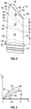
- FIG. 2 is a diagrammatic illustration of one embodiment of a rotor blade 32 for use in the turbine section 18 of the gas turbine engine 10.
- the rotor blade 32 includes an attachment 34, a platform 35, and an airfoil 36. Some embodiments of the rotor blade 32 do not include the platform 35.
- the attachment 34 may be considered as including the platform 35 for purposes of defining the beginning of the airfoil 36.
- the rotor blade attachment 34 is adapted to be received within a slot disposed within a rotor disk. Rotor blade attachments are well known in the art, and the present disclosure is not limited to any particular attachment configuration.
- the airfoil 36 has a leading edge 38, a trailing edge 40, a pressure side 42, a suction side 44, a stagger angle ⁇ , a chord and a camber line.
- the stagger angle ⁇ changes as the airfoil 36 extends between the attachment 34 and a tip 46 (e.g., the stagger angle increases in a direction defined by a line that starts at the attachment 34 and travels along the span of the airfoil 36 toward the tip 46).
- the stagger angle ⁇ is defined as the angle between a chord line 48 of the airfoil 36 and an axis (e.g., the longitudinally extending axis 30 of the gas turbine engine 10, etc.).
- the chord of the airfoil 36 changes as the airfoil 36 extends between the attachment 34 and the tip 46; e.g., the airfoil chord increases in a direction defined by a line that starts at the attachment 34 and travels along the span of the airfoil 36 toward the tip 46.
- the airfoil 36 includes a base region 50, a transition region 52 and a tip region 54.
- the base region 50 has a base height 56, a pressure side surface 58, and a suction side surface (not shown).
- the base height 56 extends between a first end 60 (also referred to as a "root") and a second end 62.
- the root 60 is located at a cross-sectional "slice" of the airfoil 36 where the base region 50 abuts the attachment 34.
- the second end 62 is located at a cross-sectional "slice" of the airfoil 36 where the base region 50 abuts the transition region 52.
- the base height 56 is approximately 50% of the span of the airfoil 36.
- the root 60 and the second end 62 each have a stagger angle 64, 66, a chord 68, 70 and camber 69, 71.
- the airfoil stagger angle increases within the base region 50 in a direction defined by a line 72 that starts at the root 60 and travels toward the second end 62; i.e., the stagger angle 66 at the second end 62 is greater than the stagger angle 64 at the root 60.
- the airfoil chord increases within the base region 50 in a direction defined by the line 72 that starts at the root 60 and travels toward the second end 62; i.e., the chord 70 at the second end 62 is greater than the chord 68 at the root 60.
- One or both the stagger angle rate of change and the chord rate of change within the base region 50 may be constant or may vary. Where either one of the stagger angle and the chord rates of change vary, an average stagger angle rate of change and/or an average chord rate of change may be used to respectively define the above referenced rates of change within the base region 50.
- the pressure side surface 58 is concave and the suction side surface is convex.
- the base region 50 additionally has non-uniform camber. Referring to FIG. 3 , camber can be defined as a rise 81 (e.g., distance) between a camber line 83 (also referred to as a "mean camber line”) and a chord line 48.
- the camber of the base region 50 can decrease in the direction defined by the line 72 such that camber 69 of the root 60 is greater than the camber 71 of the second end 62.
- the transition region 52 has a transition height 74, a pressure side surface 76 and a suction side surface (not shown).
- the transition height 74 extends between a first end 78 and a second end 80.
- the first end 78 is located at the same cross-sectional "slice" of the airfoil 36 as the second end 62 of the base region 50.
- the second end 80 is located at a cross-sectional "slice" of the airfoil 36 where the transition region 52 abuts the tip region 54.
- the transition region 52 is approximately 25% of the span of the airfoil 36.
- the first end 78 and the second end 80 each have a stagger angle 66, 82, a chord 70, 84 and camber 71, 87.
- the airfoil stagger angle increases within the transition region 52 in a direction defined by a line 86 that starts at the first end 78 and travels towards the second end 80; i.e., the stagger angle 82 at the second end 80 is greater than the stagger angle 66 at the first end 78.
- the airfoil chord increases within the transition region 52 in a direction defined by the line 86 that starts at the first end 78 and travels toward the second end 80; i.e., the chord 84 at the second end 80 is greater than the chord 70 at the first end 78.
- One or both of the stagger angle rate of change and the chord rate of change within the transition region 52 may be constant or may vary. Where either one or both of the stagger angle and chord rates of change vary, an average stagger angle rate of change and/or an average chord rate of change may be used to respectively define the above referenced rates of change within the base region 50.
- the pressure side surface 76 is concave and the suction side surface is convex.
- the transition region 52 additionally has non-uniform camber.
- the camber of the transition region 52 can decrease in the direction defined by the line 86 such that the camber 71 of the first end 78 is greater than the camber 87 of the second end 80.
- the tip region 54 has a tip height 88, a pressure side surface 90 and a suction side surface 91.
- the tip height 88 extends between a first end 92 and a second end 94 (i.e., the tip 46 of the airfoil 36).
- the first end 92 is located at the same cross-section "slice" of the airfoil 36 as the second end 80 of the transition region 52.
- the tip region 54 is approximately 20-25% of the span of the airfoil 36.
- the first end 92 and the second end 94 each have a stagger angle 82, 96, a chord 84, 98, and camber 87, 99. Referring to FIG.
- the airfoil stagger angle increases within the tip region 54 in a direction defined by a line 100 that starts at the first end 92 and travels towards the second end 94; i.e., the stagger angle 96 at the second end 94 is greater than the stagger angle 82 at the first end 92.
- the airfoil chord increases within the tip region 54 in a direction defined by the line 100 that starts at the first end 92 and travels towards the second end 94; i.e., the chord 98 at the second end 94 is greater that the chord 84 at the first end 92.
- one or both of the stagger angle rate of change and the chord rate of change within the tip region 54 may be constant or may vary.
- an average stagger angle rate of change and/or an average chord rate of change may be used to respectively define the above referenced rates of change within the base region 50.
- the pressure side surface 90 is substantially planar.
- a chord line e.g., the chordline 84, 98
- the suction side surface 91 is generally convex.
- the tip region 54 has substantially uniform camber.
- the camber 87 of the first end 92 may be substantially equal to the camber 99 of the second end 94.
- the base region 50 is disposed adjacent to the attachment 34.
- the transition region 52 is located between the base and the tip regions 50, 54.
- the airfoil 36 i.e., the base, transition and tip regions 50, 52, 54
- the airfoil 36 is additionally, or alternatively, configured such that the chord rate of change for the transition region 52 is greater than the chord rates of change for the base and the tip regions 50, 54, respectively.
- FIG. 5A is a graph illustrating the stagger angle rates of change (i.e., ⁇ ⁇ / ⁇ (Span)) of the airfoil 36 between the attachment 34 and the tip 46.
- the horizontal axis represents the stagger angle ( ⁇ ) and the vertical axis represents a distance along the span of the airfoil 36.
- FIG. 5B is a graph illustrating the chord rates of change (i.e., ⁇ (Chord)/ ⁇ (Span)) of the airfoil 36 between the attachment 34 and the tip 46.
- the horizontal axis represents the chord and the vertical axis represents a distance along the span of the airfoil 36.
- the transition region 52 has a point of inflection 104, 106 where the curvatures of the lines change from a negative value to a positive value.
- this inflection permits the base and the tip regions 50, 54 to have relatively independent airflow characteristics. That is, for example, the airfoil 36 may be configured such that the base region 50 utilizes typical airflow characteristics, while the tip region 54 utilizes airflow characteristics designed to reduce flow disturbances induced by a leakage airflow. The airflow characteristics of the tip region 54 will be described below in further detail.
- FIG. 6 is a diagrammatic illustration of the tip region 54 of the airfoil 36 in FIGS. 2 and 4 .
- a stagnation point (e.g., point "A") forms within an airflow 108 adjacent the pressure side surface 90 of the tip region 54 proximate the leading edge 38.
- a stagnation point may be defined as a point in a flow field where velocity of the airflow is approximately zero.
- the airflow 108 is divided into a pressure side airflow 110 and a suction side airflow 112.
- the pressure side airflow 110 is directed, parallel to the pressure side surface 90, from the stagnation point "A" towards the trailing edge 40. As the pressure side airflow 110 travels towards the trailing edge 40, a portion thereof (i.e., a leakage airflow 114) migrates over the tip 46 of the airfoil 36 from the pressure side airflow 110 to the suction side airflow 112.
- the leakage airflow 114 reduces the efficiency of the turbine via the unrealized work extraction that the leakage air represents and also through increased mixing losses as the leakage air is reintroduced with the mainstream suction side flow.
- the leakage airflow and the manner in which it mixes upon exiting the tip gap on the suction side are a function of the local pressure distribution around the blade tip.
- the present disclosure does not alter the amount of leakage flow.
- it alters the local pressure distribution to one more favorable for reducing the leakage mixing loss. This substantial reduction in mixing loss leads to a higher efficiency turbine.
- tip 46 is configured to have a squealer pocket 200 located in tip 46.
- the squealer pocket 200 is used in combination with the tip vortex control technology described above with respect to at least FIGS. 1-6 .
- the squealer pocket 200 comprises a cavity located in tip 46 that maintains a region or pocket of cooling fluid (e.g., air) along the tip of the airfoil, between the pressure surface and the suction surface.
- cooling fluid e.g., air
- the squealer pocket may have a plurality of cooling openings that are in fluid communication with a cooling fluid in order to provide the cooling air to the pocket 200.
- the cooling pocket is in one embodiment, surrounded by a wall or portion 202 that extends upwardly from a surface 204 of the squealer pocket 200. Wall or portion 202 is located between the leading edge 38, the trailing edge 40, the pressure side 42 and the suction side 44 of the airfoil 36.
- an inner surface or first surface 206 of the wall or portion 202 located between at least the pressure side 42 and the squealer pocket 200 extends from surface 204 to a top surface 208 of the wall or portion 202 located between at least the pressure side 42 and the squealer pocket 200.
- this inner surface 206 is configured to be arranged in, or to have, a convex configuration with respect to the pressure side 42 of the airfoil 36 as it extends from the leading edge 38 to the trailing edge 40 of the airfoil 36.
- the convex configuration may be represented by an angle 207, which is defined by the intersection of two lines tangent to surface 206 proximate to the apex of the convex portion of surface 206. In one embodiment, this angle may be between approximately -30 degrees and 30 degrees. Of course, angles greater or less than the aforementioned values are considered to be within the scope of various embodiments of the disclosure.
- an inner surface or second surface 210 of the wall or portion 202 located between at least the suction side 44 and the squealer pocket 200 extends from surface 204 to a top surface 212 of the wall or portion 202 located between at least the suction side 44 and the squealer pocket 200.
- This inner surface 206 may also be configured to have a convex shape or have a convex configuration with respect to the suction side 44 of the airfoil 36 as it extends from the leading edge 38 to the trailing edge 40 of the airfoil 36. As illustrated in FIG. 9 , these surfaces 206 and 210 may be in a facing spaced relationship with respect to each other and the cavity or squealer pocket 200 and the surface 204 are located therebetween.
- portions 214 and 216 of another inner surface of the wall or portion 202 may be located between the squealer pocket 200 and the leading edge 38 and the trailing edge 40 of the airfoil 36. These portions 214, 216 may have a different surface configuration and are located between surfaces 206 and 210.
- the combination of the tip vortex control technology described above with respect to at least FIGS. 1-6 and in combination with the squealer pocket 200 reduces the leakage over the turbine blade tip while providing additional performance benefits.
- the squealer pocket 200 also reduces a heat load to the part.
- the squealer pocket configuration creates an effective labyrinth seal which reduces the amount of tip leakage between the tip 46 and a shroud 47 or blade outer air seal (BOAS), which brings with it a performance benefit.
- BOAS blade outer air seal
- the squealer pocket provides thermal benefits as the pocket itself experiences lower heat transfer coefficients as the pocket acts as a mini-plenum which reduces the velocity of the gas path air in this region.
- the surfaces 204, 206 and 210 may be coated with any type of thermal barrier coatings, such as a ceramic coating (e.g., yttria stabilized zirconia), that do not get abraded off (even if a blade tip rub does occur) since they are recessed from the uppermost top tip surfaces. Accordingly, these thermal barrier coatings provide additional thermal benefits.
- a ceramic coating e.g., yttria stabilized zirconia
- tip 46 is configured to have a tip shelf 218 located in tip 46 proximate to the pressure surface 42 of the airfoil 36.
- the tip shelf 218 is used in combination with the tip vortex control technology described above with respect to at least FIGS. 1-6 .
- the tip shelf 218 has a ledge portion 220 extending from the pressure side 42 to a wall portion 222 extending upwardly from the ledge portion 220 to a top surface 224 of the tip 46.
- the tip shelf 218 may extend from the leading edge 38 to the trailing edge 40. Alternatively, the tip shelf 218 may only extend along a portion of the tip 46 from the leading edge 38 to the trailing edge 40.
- the surface of wall portion 222 may be generally flat and straight and is parallel to the pressure side 42 of the airfoil 36 proximate to the tip shelf 218.
- the tip shelf shape allows the cooling air to be placed where it is most beneficial and gets rid of a tip edge along the pressure surface of the airfoil that otherwise would be prone to rapid oxidation.
- the tip shelf 218 may have a plurality of cooling openings 221 that are in fluid communication with a cooling fluid 223 in order to provide cooling air to the tip shelf 218 in order to prevent the deleterious effects of high temperatures at the tip of the airfoil.
- the cooling openings 221 may be in fluid communication with an internal cooling channel or conduit 225 in fluid communication with a source of cooling air.
- the tip shelf 218 also removes the tip edge on the pressure side where the heat transfer coefficient is extremely high and is prone to rapid oxidation.
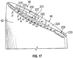
- a top view of the tip 46 of the airfoil 36 in accordance with yet another non-limiting embodiment is disclosed.
- the tip 46 is configured to have a tip shelf 218 located in tip 46 proximate to the pressure surface 42 of the airfoil 36.
- the tip shelf 218 is used in combination with the tip vortex control technology described above with respect to at least FIGS. 1-6 .
- the tip shelf 218 has a ledge portion 220 extending from the pressure side 42 to a wall portion 222 extending upwardly from the ledge portion 220 to a top surface 224 of the tip 46.
- the wall portion 222 may have a convex configuration 231 with respect to pressure surface 42.
- the convex configuration 231 of the wall portion may extend along a portion of the wall portion 222.
- the convex configuration 231 of the wall portion 222 may extend along more than 50% of the wall portion 222 but not the entire length of the wall portion 222.
- the convex configuration 231 of the wall portion may extend along the entire portion of the wall portion 222.
- any other lengths of the convex configuration 231 with respect to the wall portion 222 are considered to be within the scope of various embodiments of the present disclosure.
- the wall portion 222 may have a generally straight configuration as shown in FIGS. 10 and 11 .
- the wall portion 222 may have a convex portion 231 and a concave portion 233.
- the concave portion 233 is located proximate to the trailing edge 40 of the airfoil 36.
- the ledge portion 220 may have localized concave portion 227 as well as a localized convex portion or surface 229, which may result in wall portion 222 having varying heights as it extends upwardly from ledge portion 220.
- the tip shelf 218 may have both convex and concave inflections in the surface or ledge portion 220 as well as the wall portion 222. Tip shelf 218 may extend from the leading edge 38 to the trailing edge 40. Alternatively, the tip shelf 218 may only extend along a portion of the tip 46 from the leading edge 38 to the trailing edge 40.
- FIG. 14 is a partial cross-sectional view of the tip 36 illustrated in FIGS. 12 and 13 .
- the tip shelf shape allows the cooling air to be placed where it is most beneficial and gets rid of a tip edge along the pressure surface of the airfoil that otherwise would be prone to rapid oxidation.
- the tip shelf 218 may have a plurality of cooling openings 221 that are in fluid communication with a cooling fluid in order to provide cooling air to the tip shelf 218 in order to prevent the deleterious effects of high temperatures at the tip of the airfoil.
- the cooling openings 221 may be in fluid communication with an internal cooling channel or conduit 225 in fluid communication with a source of cooling air.
- the tip shelf 218 also removes the tip edge on the pressure side where the heat transfer coefficient is extremely high and is prone to rapid oxidation.
- a top view of the tip 46 of the airfoil 36 in accordance with yet another non-limiting embodiment is disclosed.
- tip 46 is configured to have a both the squealer pocket 200 and the tip shelf 218 as described herein with respect to any of the embodiments described in at least FIGS. 8-14 . Again, these features are in combination with the tip vortex control technology described above with respect to at least FIGS. 1-6 .
Abstract
Description
- This disclosure relates generally to gas turbine engines and, more particularly, to rotor blades for gas turbine engines.
- Typically, a rotor blade for a gas turbine engine includes an attachment (also referred to as an "attachment region") and an airfoil. The airfoil extends between the attachment and a tip and has a concave pressure side surface, a convex suction side surface, a leading edge and a trailing edge. The airfoil is sized such that when it is configured within the engine, a clearance gap is defined between the blade tip and the surrounding static structure (outer flowpath).
- During operation, a stagnation point is formed near the leading edge of the airfoil. A stagnation point may be defined as a point in a flow field where velocity of the airflow is approximately zero. At the stagnation point, the airflow separates into a pressure side airflow and a suction side airflow. The pressure side airflow travels from the stagnation point to the trailing edge. The suction side airflow is accelerated around the leading edge and a portion of the suction side surface until it reaches a point of maximum velocity. Typically, the point of maximum velocity corresponds to a point on the suction side surface where the surface becomes relatively flat as compared to a relatively curved portion of the airfoil proximate the leading edge. Thereafter, the suction side airflow decelerates as it travels from the point of maximum velocity to the trailing edge of the airfoil.
- Near the tip of the airfoil, a portion of the pressure side airflow (i.e., a leakage airflow) migrates through the tip clearance gap to the suction side airflow. This leakage airflow mixes with the suction side airflow forming a vortex. The vortex mixes out and disperses, causing relatively significant flow disturbances along the majority of the suction side surface. As a collective result of these flow disturbances, the efficiency of the engine is reduced.
- Several approaches have been adopted to try to reduce the detrimental effects associated with leakage airflows. In one approach, the clearance gap is decreased by reducing tolerances between the tip of each rotor blade and the outer flowpath. This approach has met with limited success because the tolerances must still account for thermal and centrifugal expansion of materials to prevent interference. In another approach, a shroud is attached to the tips of the rotor blades. Although air may still leak between the shroud and the outer, static flowpath, the vortex induced losses are reduced. A downside to this approach is that a shroud typically adds a significant amount of mass to the rotor, which may limit rotor operational speeds and temperatures.
- Accordingly, it is desirable to provide turbine airfoils and/or engines with airfoils that reduce the detrimental effects associated with leakage airflows.
- In one embodiment, a rotor blade for a gas turbine engine is provided. The rotor blade having: an attachment; an airfoil extending from the attachment to a tip; and a squealer pocket located in a surface of the tip, wherein the squealer pocket is at least partially surrounded by a first surface of a wall located between the squealer pocket and a pressure side of the airfoil, wherein the first surface of the wall has a convex configuration with respect to the pressure side of the airfoil as it extends from a leading edge to a trailing edge of the airfoil.
- In addition to one or more of the features described above, or as an alternative to any of the foregoing embodiments, the airfoil may have a stagger angle that changes as the airfoil extends between the attachment and the tip, the airfoil further comprising a base region disposed adjacent to the attachment, a tip region, and a transition region located between the base region and the tip region; wherein a rate of the change of the stagger angle in the transition region is greater than a rate of the change of the stagger angle in the base region; wherein the rate of the change of the stagger angle in the transition region is greater than a rate of change of the stagger angle in the tip region; and wherein the airfoil has a chord that increases as the airfoil extends from the base region to the tip.
- In addition to one or more of the features described above, or as an alternative to any of the foregoing embodiments, the squealer pocket may be at least partially surrounded by a second surface of a wall located between the squealer pocket and a suction side of the airfoil, wherein the second surface of the wall has a convex configuration with respect to the suction side of the airfoil as it extends from the leading edge to the trailing edge of the airfoil.
- In addition to one or more of the features described above, or as an alternative to any of the foregoing embodiments, the first surface and the second surface may be in a facing spaced relationship with respect to each other and the squealer pocket is located between the first surface and the second surface.
- In addition to one or more of the features described above, or as an alternative to any of the foregoing embodiments, the second surface may be partially curved and parallel to the suction side of the airfoil proximate to the tip.
- In addition to one or more of the features described above, or as an alternative to any of the foregoing embodiments, the second surface may be partially curved and parallel to the suction side of the airfoil proximate to the tip.
- In addition to one or more of the features described above, or as an alternative to any of the foregoing embodiments, the tip region may have a substantially planar pressure side surface.
- In addition to one or more of the features described above, or as an alternative to any of the foregoing embodiments, the tip region may have a chord line and a pressure side surface, and wherein the chord line is substantially parallel to the pressure side surface.
- In addition to one or more of the features described above, or as an alternative to any of the foregoing embodiments, the chord may increase as the airfoil extends from the attachment to the tip.
- In addition to one or more of the features described above, or as an alternative to any of the foregoing embodiments, the chord may change as the airfoil extends between the attachment and the tip, wherein a rate of change of the chord in the transition region is greater than a rate of change of the chord in the base region, and wherein the rate of change of the chord in the transition region is greater than a rate of change of the chord in the tip region.
- In addition to one or more of the features described above, or as an alternative to any of the foregoing embodiments, the chord of the airfoil may increase from the base region to the tip region.
- In addition to one or more of the features described above, or as an alternative to any of the foregoing embodiments, the airfoil may have a span, and wherein the tip region has a height equal to or less than approximately 25 percent of the span.
- In addition to one or more of the features described above, or as an alternative to any of the foregoing embodiments, the airfoil may have a span, and wherein the transition region has a height equal to approximately 25 percent of the span.
- In addition to one or more of the features described above, or as an alternative to any of the foregoing embodiments, the airfoil may have a span, and wherein the base region has a height equal to approximately 50 percent of the span.
- In addition to one or more of the features described above, or as an alternative to any of the foregoing embodiments, the tip region may have a substantially planar pressure side surface.
- In addition to one or more of the features described above, or as an alternative to any of the foregoing embodiments, the tip region may have a chord line and a pressure side surface, and wherein the chord line is substantially parallel to the pressure side surface.
- In addition to one or more of the features described above, or as an alternative to any of the foregoing embodiments, the chord may increase as the airfoil extends from the attachment to the tip.
- In addition to one or more of the features described above, or as an alternative to any of the foregoing embodiments, the chord may change as the airfoil extends between the attachment and the tip, wherein a rate of change of the chord in the transition region is greater than a rate of change of the chord in the base region, and wherein the rate of change of the chord in the transition region is greater than a rate of change of the chord in the tip region.
- In addition to one or more of the features described above, or as an alternative to any of the foregoing embodiments, the chord of the airfoil may increase from the base region to the tip region.
- In yet another embodiment, a gas turbine engine is provided. The gas turbine engine having: a compressor section; a combustor section; and a turbine section; wherein the turbine section includes a plurality of rotors having a plurality of radially disposed rotor blades at least some of the plurality of radially disposed rotor blades according to any of the foregoing embodiments.
- In yet another embodiment, a rotor blade for a gas turbine engine is provided. The rotor blade having: an attachment; an airfoil extending from the attachment to a tip; and a tip shelf located in a surface of the tip proximate to a pressure side of the airfoil, wherein the tip shelf has a ledge portion extending from the pressure side to a wall portion extending upwardly from the ledge portion to the tip and wherein the wall portion is configured to have a convex portion with respect to the pressure side of the airfoil as it extends from a leading edge to a trailing edge of the airfoil.
- In still yet another embodiment, a rotor blade for a gas turbine engine is provided. The rotor blade having: an attachment; an airfoil extending from the attachment to a tip; a tip shelf located in a surface of the tip proximate to a pressure side of the airfoil; and wherein the airfoil has a stagger angle that changes as the airfoil extends between the attachment and the tip, the airfoil further comprising a base region disposed adjacent to the attachment, a tip region, and a transition region located between the base region and the tip region; wherein a rate of the change of the stagger angle in the transition region is greater than a rate of the change of the stagger angle in the base region; wherein the rate of the change of the stagger angle in the transition region is greater than a rate of change of the stagger angle in the tip region; and wherein the airfoil has a chord that increases as the airfoil extends from the base region to the tip, wherein the tip shelf has a ledge portion extending from the pressure side to a wall portion extending upwardly from the ledge portion to the tip.
- In addition to one or more of the features described above, or as an alternative to any of the foregoing embodiments, the wall portion may be generally flat and straight and is parallel to the pressure side proximate to the tip shelf.
- In addition to one or more of the features described above, or as an alternative to any of the foregoing embodiments, the ledge portion may have a concave portion that results in the wall portion having varying heights as it extends upwardly from the ledge portion.
- In addition to one or more of the features described above, or as an alternative to any of the foregoing embodiments, the ledge portion may have a convex portion that results in the wall portion having varying heights as it extends upwardly from the ledge portion.
- In addition to one or more of the features described above, or as an alternative to any of the foregoing embodiments, the ledge portion may also have a convex portion that results in the wall portion having varying heights as it extends upwardly from the ledge portion wherein the convex portion of the ledge portion is located proximate to the trailing edge of the airfoil and wherein the concave portion of the ledge comprises greater than 50% of the ledge portion.
- In addition to one or more of the features described above, or as an alternative to any of the foregoing embodiments, the wall portion may be configured to have a convex portion with respect to the pressure side of the airfoil as it extends from a leading edge to a trailing edge of the airfoil.
- In addition to one or more of the features described above, or as an alternative to any of the foregoing embodiments, the convex portion of the wall portion comprises at least 50% of the wall portion that extends from the leading edge to the trailing edge of the airfoil.
- In addition to one or more of the features described above, or as an alternative to any of the foregoing embodiments, further embodiments may include a squealer pocket located in a surface of the tip.
- In addition to one or more of the features described above, or as an alternative to any of the foregoing embodiments, another portion of the wall portion may be concave with respect to pressure side of the airfoil and the another portion is located proximate to the trailing edge of the airfoil.
- In addition to one or more of the features described above, or as an alternative to any of the foregoing embodiments, the squealer pocket may be at least partially surrounded by a first surface of a wall located between the squealer pocket and the pressure side of the airfoil, wherein the first surface of the wall has a convex configuration with respect to the pressure side of the airfoil as it extends from a leading edge to a trailing edge of the airfoil.
- In addition to one or more of the features described above, or as an alternative to any of the foregoing embodiments, the squealer pocket may be at least partially surrounded by a second surface of a wall located between the squealer pocket and a suction side of the airfoil, wherein the second surface of the wall has a convex configuration with respect to the suction side of the airfoil as it extends from the leading edge to the trailing edge of the airfoil.
- In addition to one or more of the features described above, or as an alternative to any of the foregoing embodiments, the first surface and the second surface may be in a facing spaced relationship with respect to each other and the squealer pocket is located between the first surface and the second surface.
- In yet another embodiment, a gas turbine engine is provided. The gas turbine engine having: a compressor section; a combustor section; and a turbine section; wherein at least one of the turbine section and compressor section includes a plurality of rotors having a plurality of radially disposed rotor blades at least some of the plurality of radially disposed rotor blades having: an attachment; an airfoil extending from the attachment to a tip; a tip shelf located in a surface of the tip proximate to a pressure side of the airfoil, wherein the tip shelf has a ledge portion extending from the pressure side to a wall portion extending upwardly from the ledge portion to the tip and wherein the wall portion is configured to have a convex portion with respect to the pressure side of the airfoil as it extends from a leading edge to a trailing edge of the airfoil.
- In addition to one or more of the features described above, or as an alternative to any of the foregoing embodiments, the wall portion may further include a concave portion that is located proximate to the trailing edge of the airfoil.
- In addition to one or more of the features described above, or as an alternative to any of the foregoing embodiments, further embodiments may include a squealer pocket located in a surface of the tip.
- The subject matter which is regarded as the present disclosure is particularly pointed out and distinctly claimed in the claims at the conclusion of the specification. The foregoing and other features, and advantages of the present disclosure are apparent from the following detailed description by way of example only, and taken in conjunction with the accompanying drawings in which:
-
FIG. 1 is a cross-sectional view of a gas turbine engine; -
FIG. 2 is a diagrammatic illustration of a rotor blade for the gas turbine engine inFIG. 1 ; -
FIG. 3 is a diagrammatic illustration of a cross-sectional slice of an airfoil; -
FIG. 4 is a diagrammatic illustration of cross-sectional slices of an airfoil; -
FIG. 5A is a graph illustrating stagger angle rates of change of the airfoil between an attachment and a tip; -
FIG. 5B is a graph illustrating chord rates of change of the airfoil between the attachment and the tip; -
FIG. 6 is a diagrammatic illustration of airflow characteristics of a tip region of the airfoil inFIGS. 2 and4 ; -
FIG. 7 is a diagrammatic illustration of airflow characteristics of a prior art rotor blade near a tip thereof; -
FIG. 8 is top view of a tip of a rotor blade in accordance with an embodiment of the disclosure; -
FIG. 9 is a view along lines 9-9 ofFIG. 8 ; -
FIG. 10 is top view of a tip of a rotor blade in accordance with another embodiment of the disclosure; -
FIG. 11 is a view along lines 11-11 ofFIG. 10 ; -
FIGS. 12 and 13 are perspective views of a tip of a rotor blade in accordance with yet another embodiment of the disclosure; -
FIG. 14 is a cross-sectional of the tip of the rotor blade illustrated inFIGS. 12 and 13 ; -
FIG. 15 is top view of a tip of a rotor blade in accordance with yet another embodiment of the disclosure; -
FIG. 16 is a view along lines 16-16 ofFIG. 15 ; and -
FIG. 17 is a perspective view of a tip of a rotor blade in accordance with yet another embodiment of the disclosure. - Various embodiments of the present disclosure are related to turbine blades with airfoil tip vortex control. In particular and in non-limiting embodiments, various embodiments of the disclosure are related to the aforementioned turbine blades with airfoil tip vortex control configured for use in gas turbine engines and methods for cooling the blade tips of the airfoils. Although engine airfoils are discussed herein, it is understood that embodiments of this disclosure may be applied on any turbomachinery component that requires airfoil tip vortex control.
- In accordance with various embodiments of this disclosure a rotor blade for a gas turbine engine is provided. The rotor blade having an airfoil extending from an attachment to a tip and a squealer pocket and/or a tip shelf located in a surface of the tip; and the airfoil also has a stagger angle that changes as the airfoil extends between the attachment and the tip. In addition, the squealer pocket and/or tip shelf of may be of any size and aspect ratio along the tip chord.
- Various embodiments of this disclosure may be applied on any turbomachinery component that requires airfoil tip vortex control. For example, gas turbine engines are rotary-type combustion turbine engines built around a power core made up of a compressor, combustor and turbine, arranged in flow series with an upstream inlet and downstream exhaust. The compressor compresses air from the inlet, which is mixed with fuel in the combustor and ignited to generate hot combustion gas. The turbine extracts energy from the expanding combustion gas, and drives the compressor via a common shaft. Energy is delivered in the form of rotational energy in the shaft, reactive thrust from the exhaust, or both.
- Gas turbine engines provide efficient, reliable power for a wide range of applications, including aviation and industrial power generation. Smaller-scale engines such as auxiliary power units typically utilize a one-spool design, with co-rotating compressor and turbine sections. Larger-scale jet engines and industrial gas turbines are generally arranged into a number of coaxially nested spools, which operate at different pressures and temperatures, and rotate at different speeds.
- The individual compressor and turbine sections in each spool are subdivided into a number of stages, which are formed of alternating rows of rotor blade and stator vane airfoils. The airfoils are shaped to turn, accelerate and compress the working fluid flow, or to generate lift for conversion to rotational energy in the turbine.
- Aviation applications include turbojet, turbofan, turboprop and turboshaft engines. In turbojet engines, thrust is generated primarily from the exhaust. Modern fixed-wing aircraft generally employ turbofan and turboprop designs, in which the low pressure spool is coupled to a propulsion fan or propeller. Turboshaft engines are typically used on rotary-wing aircraft, including helicopters.
- Turbofan engines are commonly divided into high and low bypass configurations. High bypass turbofans generate thrust primarily from the fan, which drives airflow through a bypass duct oriented around the engine core. This design is common on commercial aircraft and military transports, where noise and fuel efficiency are primary concerns. Low bypass turbofans generate proportionally more thrust from the exhaust flow, providing greater specific thrust for use on high-performance aircraft, including supersonic jet fighters. Unducted (open rotor) turbofans and ducted propeller engines are also known, in a variety of counter-rotating and aft-mounted configurations.
- Turbofan engine performance depends on precise control of the working fluid flow, including flow across the airfoil tip. Where clearance, abrasion and temperature effects are of concern, moreover, these factors often pose competing design demands on compressor and turbine rotor geometry, particularly in the tip region of the airfoil.
- Referring to
FIG. 1 , agas turbine engine 10 includes afan 12, acompressor section 14, acombustor section 16, aturbine section 18, and anozzle 20. The compressor andturbine sections stator vane stage rotor stage turbine sections longitudinally extending axis 30 of theengine 10. -
FIG. 2 is a diagrammatic illustration of one embodiment of arotor blade 32 for use in theturbine section 18 of thegas turbine engine 10. Therotor blade 32 includes anattachment 34, aplatform 35, and anairfoil 36. Some embodiments of therotor blade 32 do not include theplatform 35. To simplify the description herein, theattachment 34 may be considered as including theplatform 35 for purposes of defining the beginning of theairfoil 36. Therotor blade attachment 34 is adapted to be received within a slot disposed within a rotor disk. Rotor blade attachments are well known in the art, and the present disclosure is not limited to any particular attachment configuration. - The
airfoil 36 has aleading edge 38, a trailingedge 40, apressure side 42, asuction side 44, a stagger angle φ, a chord and a camber line. The stagger angle φ changes as theairfoil 36 extends between theattachment 34 and a tip 46 (e.g., the stagger angle increases in a direction defined by a line that starts at theattachment 34 and travels along the span of theairfoil 36 toward the tip 46). Referring toFIG. 3 , the stagger angle φ is defined as the angle between achord line 48 of theairfoil 36 and an axis (e.g., thelongitudinally extending axis 30 of thegas turbine engine 10, etc.). Therefore, the stagger angle φ for one cross-sectional "slice" of theairfoil 36 may be calculated using the following equation: φstagger = tan-1(ΔY/ΔX) where ΔY is indicative of a distance between tips of the leading and the trailingedges airfoil 36 along a y-axis, and ΔX is indicative of a distance between the tips of the leading and the trailingedges airfoil 36 along an x-axis. Additionally, or alternatively, the chord of theairfoil 36 changes as theairfoil 36 extends between theattachment 34 and thetip 46; e.g., the airfoil chord increases in a direction defined by a line that starts at theattachment 34 and travels along the span of theairfoil 36 toward thetip 46. Referring again toFIG. 2 , theairfoil 36 includes abase region 50, atransition region 52 and atip region 54. - The
base region 50 has abase height 56, apressure side surface 58, and a suction side surface (not shown). Thebase height 56 extends between a first end 60 (also referred to as a "root") and asecond end 62. Theroot 60 is located at a cross-sectional "slice" of theairfoil 36 where thebase region 50 abuts theattachment 34. Thesecond end 62 is located at a cross-sectional "slice" of theairfoil 36 where thebase region 50 abuts thetransition region 52. In some embodiments, thebase height 56 is approximately 50% of the span of theairfoil 36. Theroot 60 and thesecond end 62 each have a staggerangle chord 68, 70 andcamber FIG. 4 , the airfoil stagger angle increases within thebase region 50 in a direction defined by aline 72 that starts at theroot 60 and travels toward thesecond end 62; i.e., the staggerangle 66 at thesecond end 62 is greater than the staggerangle 64 at theroot 60. Additionally, or alternatively, the airfoil chord increases within thebase region 50 in a direction defined by theline 72 that starts at theroot 60 and travels toward thesecond end 62; i.e., the chord 70 at thesecond end 62 is greater than thechord 68 at theroot 60. One or both the stagger angle rate of change and the chord rate of change within thebase region 50 may be constant or may vary. Where either one of the stagger angle and the chord rates of change vary, an average stagger angle rate of change and/or an average chord rate of change may be used to respectively define the above referenced rates of change within thebase region 50. Thepressure side surface 58 is concave and the suction side surface is convex. In some embodiments, thebase region 50 additionally has non-uniform camber. Referring toFIG. 3 , camber can be defined as a rise 81 (e.g., distance) between a camber line 83 (also referred to as a "mean camber line") and achord line 48. For example, referring to the embodiment inFIG. 4 , the camber of thebase region 50 can decrease in the direction defined by theline 72 such thatcamber 69 of theroot 60 is greater than thecamber 71 of thesecond end 62. - Referring to
FIG. 2 , thetransition region 52 has atransition height 74, apressure side surface 76 and a suction side surface (not shown). Thetransition height 74 extends between afirst end 78 and asecond end 80. Thefirst end 78 is located at the same cross-sectional "slice" of theairfoil 36 as thesecond end 62 of thebase region 50. Thesecond end 80 is located at a cross-sectional "slice" of theairfoil 36 where thetransition region 52 abuts thetip region 54. In some embodiments, thetransition region 52 is approximately 25% of the span of theairfoil 36. Thefirst end 78 and thesecond end 80 each have a staggerangle chord 70, 84 andcamber FIG. 4 , the airfoil stagger angle increases within thetransition region 52 in a direction defined by aline 86 that starts at thefirst end 78 and travels towards thesecond end 80; i.e., the staggerangle 82 at thesecond end 80 is greater than the staggerangle 66 at thefirst end 78. Additionally or alternatively, the airfoil chord increases within thetransition region 52 in a direction defined by theline 86 that starts at thefirst end 78 and travels toward thesecond end 80; i.e., thechord 84 at thesecond end 80 is greater than the chord 70 at thefirst end 78. One or both of the stagger angle rate of change and the chord rate of change within thetransition region 52 may be constant or may vary. Where either one or both of the stagger angle and chord rates of change vary, an average stagger angle rate of change and/or an average chord rate of change may be used to respectively define the above referenced rates of change within thebase region 50. Thepressure side surface 76 is concave and the suction side surface is convex. In some embodiments, thetransition region 52 additionally has non-uniform camber. For example, the camber of thetransition region 52 can decrease in the direction defined by theline 86 such that thecamber 71 of thefirst end 78 is greater than thecamber 87 of thesecond end 80. - Referring to
FIG. 2 , thetip region 54 has atip height 88, apressure side surface 90 and asuction side surface 91. Thetip height 88 extends between afirst end 92 and a second end 94 (i.e., thetip 46 of the airfoil 36). Thefirst end 92 is located at the same cross-section "slice" of theairfoil 36 as thesecond end 80 of thetransition region 52. In some embodiments, thetip region 54 is approximately 20-25% of the span of theairfoil 36. Thefirst end 92 and thesecond end 94 each have a staggerangle chord camber FIG. 4 , the airfoil stagger angle increases within thetip region 54 in a direction defined by aline 100 that starts at thefirst end 92 and travels towards thesecond end 94; i.e., the staggerangle 96 at thesecond end 94 is greater than the staggerangle 82 at thefirst end 92. Additionally or alternatively, the airfoil chord increases within thetip region 54 in a direction defined by theline 100 that starts at thefirst end 92 and travels towards thesecond end 94; i.e., thechord 98 at thesecond end 94 is greater that thechord 84 at thefirst end 92. Notably, one or both of the stagger angle rate of change and the chord rate of change within thetip region 54 may be constant or may vary. Where either one or both of the stagger angle and chord rates of change vary, an average stagger angle rate of change and/or an average chord rate of change may be used to respectively define the above referenced rates of change within thebase region 50. Thepressure side surface 90 is substantially planar. For example, in one embodiment, a chord line (e.g., thechordline 84, 98) of thetip region 54 is substantially parallel to thepressure side surface 90 between the first and the second ends 92, 94. Thesuction side surface 91 is generally convex. In some embodiments, thetip region 54 has substantially uniform camber. For example, thecamber 87 of thefirst end 92 may be substantially equal to thecamber 99 of thesecond end 94. - Referring to
FIG. 2 , thebase region 50 is disposed adjacent to theattachment 34. Thetransition region 52 is located between the base and thetip regions FIG. 4 , the airfoil 36 (i.e., the base, transition andtip regions transition region 52 is greater than the stagger angle rates of change for the base and thetip regions airfoil 36 is additionally, or alternatively, configured such that the chord rate of change for thetransition region 52 is greater than the chord rates of change for the base and thetip regions -
FIG. 5A is a graph illustrating the stagger angle rates of change (i.e., Δ φ / Δ (Span)) of theairfoil 36 between theattachment 34 and thetip 46. The horizontal axis represents the stagger angle (φ) and the vertical axis represents a distance along the span of theairfoil 36.FIG. 5B is a graph illustrating the chord rates of change (i.e., Δ (Chord)/ Δ (Span)) of theairfoil 36 between theattachment 34 and thetip 46. The horizontal axis represents the chord and the vertical axis represents a distance along the span of theairfoil 36. As illustrated inFIGS. 5A and 5B , thetransition region 52 has a point ofinflection 104, 106 where the curvatures of the lines change from a negative value to a positive value. Significantly, it is believed that this inflection permits the base and thetip regions airfoil 36 may be configured such that thebase region 50 utilizes typical airflow characteristics, while thetip region 54 utilizes airflow characteristics designed to reduce flow disturbances induced by a leakage airflow. The airflow characteristics of thetip region 54 will be described below in further detail. -
FIG. 6 is a diagrammatic illustration of thetip region 54 of theairfoil 36 inFIGS. 2 and4 . Referring toFIG. 6 , in operation, a stagnation point (e.g., point "A") forms within anairflow 108 adjacent thepressure side surface 90 of thetip region 54 proximate theleading edge 38. As set forth above, a stagnation point may be defined as a point in a flow field where velocity of the airflow is approximately zero. At the stagnation point "A", theairflow 108 is divided into apressure side airflow 110 and asuction side airflow 112. - The
pressure side airflow 110 is directed, parallel to thepressure side surface 90, from the stagnation point "A" towards the trailingedge 40. As thepressure side airflow 110 travels towards the trailingedge 40, a portion thereof (i.e., a leakage airflow 114) migrates over thetip 46 of theairfoil 36 from thepressure side airflow 110 to thesuction side airflow 112. - The
leakage airflow 114 reduces the efficiency of the turbine via the unrealized work extraction that the leakage air represents and also through increased mixing losses as the leakage air is reintroduced with the mainstream suction side flow. The leakage airflow and the manner in which it mixes upon exiting the tip gap on the suction side are a function of the local pressure distribution around the blade tip. In contrast to prior art rotor blades which aim to reduce the tip leakage, the present disclosure does not alter the amount of leakage flow. In contrast, it alters the local pressure distribution to one more favorable for reducing the leakage mixing loss. This substantial reduction in mixing loss leads to a higher efficiency turbine. - Referring now to
FIGS. 8 and 9 , a top view of thetip 46 of theairfoil 36 in accordance with one non-limiting embodiment is disclosed. Heretip 46 is configured to have asquealer pocket 200 located intip 46. In one embodiment, thesquealer pocket 200 is used in combination with the tip vortex control technology described above with respect to at leastFIGS. 1-6 . Thesquealer pocket 200 comprises a cavity located intip 46 that maintains a region or pocket of cooling fluid (e.g., air) along the tip of the airfoil, between the pressure surface and the suction surface. In one embodiment, the squealer pocket may have a plurality of cooling openings that are in fluid communication with a cooling fluid in order to provide the cooling air to thepocket 200. The cooling pocket is in one embodiment, surrounded by a wall orportion 202 that extends upwardly from asurface 204 of thesquealer pocket 200. Wall orportion 202 is located between theleading edge 38, the trailingedge 40, thepressure side 42 and thesuction side 44 of theairfoil 36. - In one embodiment an inner surface or
first surface 206 of the wall orportion 202 located between at least thepressure side 42 and thesquealer pocket 200 extends fromsurface 204 to atop surface 208 of the wall orportion 202 located between at least thepressure side 42 and thesquealer pocket 200. In one embodiment, thisinner surface 206 is configured to be arranged in, or to have, a convex configuration with respect to thepressure side 42 of theairfoil 36 as it extends from the leadingedge 38 to the trailingedge 40 of theairfoil 36. The convex configuration may be represented by anangle 207, which is defined by the intersection of two lines tangent to surface 206 proximate to the apex of the convex portion ofsurface 206. In one embodiment, this angle may be between approximately -30 degrees and 30 degrees. Of course, angles greater or less than the aforementioned values are considered to be within the scope of various embodiments of the disclosure. - In addition, an inner surface or
second surface 210 of the wall orportion 202 located between at least thesuction side 44 and thesquealer pocket 200 extends fromsurface 204 to atop surface 212 of the wall orportion 202 located between at least thesuction side 44 and thesquealer pocket 200. Thisinner surface 206 may also be configured to have a convex shape or have a convex configuration with respect to thesuction side 44 of theairfoil 36 as it extends from the leadingedge 38 to the trailingedge 40 of theairfoil 36. As illustrated inFIG. 9 , thesesurfaces squealer pocket 200 and thesurface 204 are located therebetween. - Still further,
portions portion 202 may be located between thesquealer pocket 200 and the leadingedge 38 and the trailingedge 40 of theairfoil 36. Theseportions surfaces - The combination of the tip vortex control technology described above with respect to at least
FIGS. 1-6 and in combination with thesquealer pocket 200 reduces the leakage over the turbine blade tip while providing additional performance benefits. In addition to reducing the leakage flow over the tip thesquealer pocket 200 also reduces a heat load to the part. The squealer pocket configuration creates an effective labyrinth seal which reduces the amount of tip leakage between thetip 46 and ashroud 47 or blade outer air seal (BOAS), which brings with it a performance benefit. The squealer pocket provides thermal benefits as the pocket itself experiences lower heat transfer coefficients as the pocket acts as a mini-plenum which reduces the velocity of the gas path air in this region. In addition, thesurfaces - Referring now to at least
FIGS. 10 and 11 , a top view of thetip 46 of the airfoil in accordance with another one non-limiting embodiment is disclosed. Heretip 46 is configured to have atip shelf 218 located intip 46 proximate to thepressure surface 42 of theairfoil 36. In one embodiment, thetip shelf 218 is used in combination with the tip vortex control technology described above with respect to at leastFIGS. 1-6 . In this embodiment, thetip shelf 218 has aledge portion 220 extending from thepressure side 42 to awall portion 222 extending upwardly from theledge portion 220 to atop surface 224 of thetip 46. In one embodiment, thetip shelf 218 may extend from the leadingedge 38 to the trailingedge 40. Alternatively, thetip shelf 218 may only extend along a portion of thetip 46 from the leadingedge 38 to the trailingedge 40. - In one embodiment, the surface of
wall portion 222 may be generally flat and straight and is parallel to thepressure side 42 of theairfoil 36 proximate to thetip shelf 218. - The combination of the tip vortex control technology described above with respect to at least
FIGS. 1-6 and in combination with thetip shelf 218 reduces the leakage over the turbine blade tip while providing additional performance benefits. In this embodiment, the tip shelf shape allows the cooling air to be placed where it is most beneficial and gets rid of a tip edge along the pressure surface of the airfoil that otherwise would be prone to rapid oxidation. In one embodiment, thetip shelf 218 may have a plurality of coolingopenings 221 that are in fluid communication with a cooling fluid 223 in order to provide cooling air to thetip shelf 218 in order to prevent the deleterious effects of high temperatures at the tip of the airfoil. The coolingopenings 221 may be in fluid communication with an internal cooling channel orconduit 225 in fluid communication with a source of cooling air. As mentioned above, thetip shelf 218 also removes the tip edge on the pressure side where the heat transfer coefficient is extremely high and is prone to rapid oxidation. - In yet another embodiment and as illustrated in at least
FIGS. 12 and 13 , a top view of thetip 46 of theairfoil 36 in accordance with yet another non-limiting embodiment is disclosed. In this embodiment, thetip 46 is configured to have atip shelf 218 located intip 46 proximate to thepressure surface 42 of theairfoil 36. In one embodiment, thetip shelf 218 is used in combination with the tip vortex control technology described above with respect to at leastFIGS. 1-6 . In this embodiment, thetip shelf 218 has aledge portion 220 extending from thepressure side 42 to awall portion 222 extending upwardly from theledge portion 220 to atop surface 224 of thetip 46. In one embodiment, thewall portion 222 may have aconvex configuration 231 with respect topressure surface 42. In one embodiment, theconvex configuration 231 of the wall portion may extend along a portion of thewall portion 222. In one configuration, theconvex configuration 231 of thewall portion 222 may extend along more than 50% of thewall portion 222 but not the entire length of thewall portion 222. In yet another embodiment, theconvex configuration 231 of the wall portion may extend along the entire portion of thewall portion 222. Of course, any other lengths of theconvex configuration 231 with respect to thewall portion 222 are considered to be within the scope of various embodiments of the present disclosure. Alternatively, thewall portion 222 may have a generally straight configuration as shown inFIGS. 10 and 11 . Still further and in yet another alternative embodiment, thewall portion 222 may have aconvex portion 231 and aconcave portion 233. In one embodiment, theconcave portion 233 is located proximate to the trailingedge 40 of theairfoil 36. In addition, theledge portion 220 may have localizedconcave portion 227 as well as a localized convex portion orsurface 229, which may result inwall portion 222 having varying heights as it extends upwardly fromledge portion 220. Thus and in this embodiment, thetip shelf 218 may have both convex and concave inflections in the surface orledge portion 220 as well as thewall portion 222.Tip shelf 218 may extend from the leadingedge 38 to the trailingedge 40. Alternatively, thetip shelf 218 may only extend along a portion of thetip 46 from the leadingedge 38 to the trailingedge 40.FIG. 14 is a partial cross-sectional view of thetip 36 illustrated inFIGS. 12 and 13 . - The combination of the tip vortex control technology described above with respect to at least
FIGS. 1-6 and in combination with thetip shelf 218 reduces the leakage over the turbine blade tip while providing additional performance benefits. In this embodiment, the tip shelf shape allows the cooling air to be placed where it is most beneficial and gets rid of a tip edge along the pressure surface of the airfoil that otherwise would be prone to rapid oxidation. In one embodiment, thetip shelf 218 may have a plurality of coolingopenings 221 that are in fluid communication with a cooling fluid in order to provide cooling air to thetip shelf 218 in order to prevent the deleterious effects of high temperatures at the tip of the airfoil. The coolingopenings 221 may be in fluid communication with an internal cooling channel orconduit 225 in fluid communication with a source of cooling air. As mentioned above, thetip shelf 218 also removes the tip edge on the pressure side where the heat transfer coefficient is extremely high and is prone to rapid oxidation. - In yet another embodiment and as illustrated in at least
FIGS. 15-17 , a top view of thetip 46 of theairfoil 36 in accordance with yet another non-limiting embodiment is disclosed. Heretip 46 is configured to have a both thesquealer pocket 200 and thetip shelf 218 as described herein with respect to any of the embodiments described in at leastFIGS. 8-14 . Again, these features are in combination with the tip vortex control technology described above with respect to at leastFIGS. 1-6 . - While the present disclosure has been described in detail in connection with only a limited number of embodiments, it should be readily understood that the present disclosure is not limited to such disclosed embodiments. Rather, the present disclosure can be modified to incorporate any number of variations, alterations, substitutions or equivalent arrangements not heretofore described, but which are commensurate with the scope of the present disclosure as set out in the claims. Additionally, while various embodiments of the present disclosure have been described, it is to be understood that aspects of the present disclosure may include only some of the described embodiments. Accordingly, the present disclosure is not to be seen as limited by the foregoing description, but is only limited by the scope of the appended claims.
- A further aspect of the disclosure is set out below in the following clause.
- 1. A gas turbine engine, comprising:
- a compressor section;
- a combustor section; and
- a turbine section; wherein the turbine section includes a plurality of rotors having a plurality of radially disposed rotor blades at least some of the plurality of radially disposed rotor blades having:
- an attachment;
- an airfoil extending from the attachment to a tip; and
- a squealer pocket located in a surface of the tip, wherein the squealer pocket is at least partially surrounded by a first surface of a wall located between the squealer pocket and a pressure side of the airfoil, wherein the first surface of the wall has a convex configuration with respect to the pressure side of the airfoil as it extends from a leading edge to a trailing edge of the airfoil.
Claims (14)
- A rotor blade (32) for a gas turbine engine (10), comprising:an attachment (34);an airfoil (36) extending from the attachment to a tip (46); anda squealer pocket (200) located in a surface of the tip, wherein the squealer pocket is at least partially surrounded by a first surface (206) of a wall (202) located between the squealer pocket and a pressure side (42) of the airfoil, wherein the first surface of the wall has a convex configuration with respect to the pressure side of the airfoil as it extends from a leading edge (38) to a trailing edge (40) of the airfoil.
- The rotor blade of claim 1, wherein the airfoil has a stagger angle (φ; 64; 66; 82; 96) that changes as the airfoil extends between the attachment and the tip, the airfoil further comprising a base region (50) disposed adjacent to the attachment, a tip region (54), and a transition region (52) located between the base region and the tip region; wherein a rate of the change of the stagger angle (66; 82) in the transition region is greater than a rate of the change of the stagger angle (64; 66) in the base region; wherein the rate of the change of the stagger angle (66; 82) in the transition region is greater than a rate of change of the stagger angle (82; 96) in the tip region; and wherein the airfoil has a chord (48; 68; 70; 84; 98) that increases as the airfoil extends from the base region to the tip.
- The rotor blade of claim 1 or 2, wherein the squealer pocket is at least partially surrounded by a second surface (210) of a wall (202) located between the squealer pocket and a suction side (44) of the airfoil, wherein the second surface of the wall has a convex configuration with respect to the suction side of the airfoil as it extends from the leading edge to the trailing edge of the airfoil.
- The rotor blade of claim 3, wherein the first surface and the second surface are in a facing spaced relationship with respect to each other and the squealer pocket is located between the first surface and the second surface.
- The rotor blade of claim 3 or 4, wherein the second surface is partially curved and parallel to the suction side of the airfoil proximate to the tip.
- The rotor blade of claim 2, wherein the tip region has a substantially planar pressure side surface (90).
- The rotor blade of claim 2, wherein the tip region has a chord line (84; 98) and a pressure side surface (90), and wherein the chord line is substantially parallel to the pressure side surface.
- The rotor blade of claim 6 or 7, wherein the chord increases as the airfoil extends from the attachment to the tip.
- The rotor blade of claim 6 or 7, wherein the chord changes as the airfoil extends between the attachment and the tip, wherein a rate of change of the chord (70; 84) in the transition region is greater than a rate of change of the chord (68; 70) in the base region, and wherein the rate of change of the chord (70; 84) in the transition region is greater than a rate of change of the chord (68; 70) in the tip region.
- The rotor blade of claim 9, wherein the chord of the airfoil increases from the base region to the tip region.
- The rotor blade of any of claims 6 to 10, wherein airfoil has a span, and wherein the tip region has a height (88) equal to or less than approximately 25 percent of the span.
- The rotor blade of any of claims 6 to 11, wherein airfoil has a span, and wherein the transition region has a height (74) equal to approximately 25 percent of the span.
- The rotor blade of any of claims 6 to 12, wherein airfoil has a span, and wherein the base region has a height (56) equal to approximately 50 percent of the span.
- A gas turbine engine (10), comprising:a compressor section (14);a combustor section (16); anda turbine section (18); wherein the turbine section includes a plurality of rotors (28) having a plurality of radially disposed rotor blades (32), at least some of the plurality of radially disposed rotor blades being a rotor blade as claimed in any preceding claim.
Applications Claiming Priority (2)
| Application Number | Priority Date | Filing Date | Title |
|---|---|---|---|
| US201562258834P | 2015-11-23 | 2015-11-23 | |
| US15/018,025 US20170145827A1 (en) | 2015-11-23 | 2016-02-08 | Turbine blade with airfoil tip vortex control |
Publications (2)
| Publication Number | Publication Date |
|---|---|
| EP3170974A1 true EP3170974A1 (en) | 2017-05-24 |
| EP3170974B1 EP3170974B1 (en) | 2021-06-02 |
Family
ID=57391917
Family Applications (1)
| Application Number | Title | Priority Date | Filing Date |
|---|---|---|---|
| EP16200356.0A Active EP3170974B1 (en) | 2015-11-23 | 2016-11-23 | Turbine blade with airfoil tip vortex control |
Country Status (2)
| Country | Link |
|---|---|
| US (1) | US20170145827A1 (en) |
| EP (1) | EP3170974B1 (en) |
Cited By (2)
| Publication number | Priority date | Publication date | Assignee | Title |
|---|---|---|---|---|
| DE102019202388A1 (en) * | 2019-02-21 | 2020-08-27 | MTU Aero Engines AG | Shroudless blade for a high-speed turbine stage |
| US11230933B2 (en) | 2019-02-21 | 2022-01-25 | MTU Aero Engines AG | Blade for a high-speed turbine stage having a single sealing element |
Families Citing this family (3)
| Publication number | Priority date | Publication date | Assignee | Title |
|---|---|---|---|---|
| KR101984397B1 (en) * | 2017-09-29 | 2019-05-30 | 두산중공업 주식회사 | Rotor, turbine and gas turbine comprising the same |
| US10787932B2 (en) * | 2018-07-13 | 2020-09-29 | Honeywell International Inc. | Turbine blade with dust tolerant cooling system |
| FR3089553B1 (en) * | 2018-12-11 | 2021-01-22 | Safran Aircraft Engines | TURBOMACHINE DAWN AT ARROW LAW WITH HIGH MARGIN AT FLOTATION |
Citations (4)
| Publication number | Priority date | Publication date | Assignee | Title |
|---|---|---|---|---|
| US20080044291A1 (en) * | 2006-08-21 | 2008-02-21 | General Electric Company | Counter tip baffle airfoil |
| US20100303625A1 (en) * | 2009-05-27 | 2010-12-02 | Craig Miller Kuhne | Recovery tip turbine blade |
| EP2333242A2 (en) * | 2009-12-04 | 2011-06-15 | United Technologies Corporation | Tip vortex control on a rotor blade for a gas turbine engine |
| WO2015094498A1 (en) * | 2013-12-17 | 2015-06-25 | United Technologies Corporation | Enhanced cooling for blade tip |
Family Cites Families (14)
| Publication number | Priority date | Publication date | Assignee | Title |
|---|---|---|---|---|
| US7581930B2 (en) * | 2006-08-16 | 2009-09-01 | United Technologies Corporation | High lift transonic turbine blade |
| US8632311B2 (en) * | 2006-08-21 | 2014-01-21 | General Electric Company | Flared tip turbine blade |
| US8512003B2 (en) * | 2006-08-21 | 2013-08-20 | General Electric Company | Tip ramp turbine blade |
| FR2907157A1 (en) * | 2006-10-13 | 2008-04-18 | Snecma Sa | MOBILE AUB OF TURBOMACHINE |
| US8439643B2 (en) * | 2009-08-20 | 2013-05-14 | General Electric Company | Biformal platform turbine blade |
| US8303254B1 (en) * | 2009-09-14 | 2012-11-06 | Florida Turbine Technologies, Inc. | Turbine blade with tip edge cooling |
| GB201100957D0 (en) * | 2011-01-20 | 2011-03-02 | Rolls Royce Plc | Rotor blade |
| KR101324249B1 (en) * | 2011-12-06 | 2013-11-01 | 삼성테크윈 주식회사 | Turbine impeller comprising a blade with squealer tip |
| US9017036B2 (en) * | 2012-02-29 | 2015-04-28 | United Technologies Corporation | High order shaped curve region for an airfoil |
| US9470096B2 (en) * | 2012-07-26 | 2016-10-18 | General Electric Company | Turbine bucket with notched squealer tip |
| WO2015069411A1 (en) * | 2013-11-11 | 2015-05-14 | United Technologies Corporation | Gas turbine engine turbine blade tip cooling |
| US20150345301A1 (en) * | 2014-05-29 | 2015-12-03 | General Electric Company | Rotor blade cooling flow |
| US20160319672A1 (en) * | 2015-04-29 | 2016-11-03 | General Electric Company | Rotor blade having a flared tip |
| US10253637B2 (en) * | 2015-12-11 | 2019-04-09 | General Electric Company | Method and system for improving turbine blade performance |
-
2016
- 2016-02-08 US US15/018,025 patent/US20170145827A1/en not_active Abandoned
- 2016-11-23 EP EP16200356.0A patent/EP3170974B1/en active Active
Patent Citations (4)
| Publication number | Priority date | Publication date | Assignee | Title |
|---|---|---|---|---|
| US20080044291A1 (en) * | 2006-08-21 | 2008-02-21 | General Electric Company | Counter tip baffle airfoil |
| US20100303625A1 (en) * | 2009-05-27 | 2010-12-02 | Craig Miller Kuhne | Recovery tip turbine blade |
| EP2333242A2 (en) * | 2009-12-04 | 2011-06-15 | United Technologies Corporation | Tip vortex control on a rotor blade for a gas turbine engine |
| WO2015094498A1 (en) * | 2013-12-17 | 2015-06-25 | United Technologies Corporation | Enhanced cooling for blade tip |
Cited By (3)
| Publication number | Priority date | Publication date | Assignee | Title |
|---|---|---|---|---|
| DE102019202388A1 (en) * | 2019-02-21 | 2020-08-27 | MTU Aero Engines AG | Shroudless blade for a high-speed turbine stage |
| US11230933B2 (en) | 2019-02-21 | 2022-01-25 | MTU Aero Engines AG | Blade for a high-speed turbine stage having a single sealing element |
| US11788415B2 (en) | 2019-02-21 | 2023-10-17 | MTU Aero Engines AG | Shroudless blade for a high-speed turbine stage |
Also Published As
| Publication number | Publication date |
|---|---|
| EP3170974B1 (en) | 2021-06-02 |
| US20170145827A1 (en) | 2017-05-25 |
Similar Documents
| Publication | Publication Date | Title |
|---|---|---|
| EP3179035B1 (en) | Turbine blade with airfoil tip vortex control | |
| US9284845B2 (en) | Turbine airfoil tip shelf and squealer pocket cooling | |
| US9017037B2 (en) | Rotor with flattened exit pressure profile | |
| US8360731B2 (en) | Tip vortex control | |
| US8807930B2 (en) | Non axis-symmetric stator vane endwall contour | |
| EP3170974B1 (en) | Turbine blade with airfoil tip vortex control | |
| US8702398B2 (en) | High camber compressor rotor blade | |
| EP2689108B1 (en) | Compressor airfoil with tip dihedral | |
| US9074483B2 (en) | High camber stator vane | |
| US10184340B2 (en) | Geared turbofan engine having a reduced number of fan blades and improved acoustics | |
| US9228442B2 (en) | Turbine airfoil tip shelf and squealer pocket cooling | |
| EP3150803B1 (en) | Airfoil and method of cooling | |
| US9429027B2 (en) | Turbine airfoil tip shelf and squealer pocket cooling | |
| EP3118413B1 (en) | Turbine airfoil tip shelf and squealer pocket cooling | |
| US9145775B2 (en) | Tapered thermal coating for airfoil | |
| US20210270137A1 (en) | Turbine engine with airfoil having high acceleration and low blade turning |
Legal Events
| Date | Code | Title | Description |
|---|---|---|---|
| PUAI | Public reference made under article 153(3) epc to a published international application that has entered the european phase |
Free format text: ORIGINAL CODE: 0009012 |
|
| STAA | Information on the status of an ep patent application or granted ep patent |
Free format text: STATUS: THE APPLICATION HAS BEEN PUBLISHED |
|
| AK | Designated contracting states |
Kind code of ref document: A1 Designated state(s): AL AT BE BG CH CY CZ DE DK EE ES FI FR GB GR HR HU IE IS IT LI LT LU LV MC MK MT NL NO PL PT RO RS SE SI SK SM TR |
|
| AX | Request for extension of the european patent |
Extension state: BA ME |
|
| STAA | Information on the status of an ep patent application or granted ep patent |
Free format text: STATUS: REQUEST FOR EXAMINATION WAS MADE |
|
| 17P | Request for examination filed |
Effective date: 20171124 |
|
| RBV | Designated contracting states (corrected) |
Designated state(s): AL AT BE BG CH CY CZ DE DK EE ES FI FR GB GR HR HU IE IS IT LI LT LU LV MC MK MT NL NO PL PT RO RS SE SI SK SM TR |
|
| STAA | Information on the status of an ep patent application or granted ep patent |
Free format text: STATUS: EXAMINATION IS IN PROGRESS |
|
| 17Q | First examination report despatched |
Effective date: 20200414 |
|
| GRAP | Despatch of communication of intention to grant a patent |
Free format text: ORIGINAL CODE: EPIDOSNIGR1 |
|
| STAA | Information on the status of an ep patent application or granted ep patent |
Free format text: STATUS: GRANT OF PATENT IS INTENDED |
|
| INTG | Intention to grant announced |
Effective date: 20210112 |
|
| RAP1 | Party data changed (applicant data changed or rights of an application transferred) |
Owner name: RAYTHEON TECHNOLOGIES CORPORATION |
|
| GRAS | Grant fee paid |
Free format text: ORIGINAL CODE: EPIDOSNIGR3 |
|
| GRAA | (expected) grant |
Free format text: ORIGINAL CODE: 0009210 |
|
| STAA | Information on the status of an ep patent application or granted ep patent |
Free format text: STATUS: THE PATENT HAS BEEN GRANTED |
|
| REG | Reference to a national code |
Ref country code: CH Ref legal event code: EP |
|
| AK | Designated contracting states |
Kind code of ref document: B1 Designated state(s): AL AT BE BG CH CY CZ DE DK EE ES FI FR GB GR HR HU IE IS IT LI LT LU LV MC MK MT NL NO PL PT RO RS SE SI SK SM TR |
|
| REG | Reference to a national code |
Ref country code: GB Ref legal event code: FG4D |
|
| REG | Reference to a national code |
Ref country code: AT Ref legal event code: REF Ref document number: 1398599 Country of ref document: AT Kind code of ref document: T Effective date: 20210615 |
|
| REG | Reference to a national code |
Ref country code: IE Ref legal event code: FG4D |
|
| REG | Reference to a national code |
Ref country code: DE Ref legal event code: R096 Ref document number: 602016058745 Country of ref document: DE |
|
| REG | Reference to a national code |
Ref country code: LT Ref legal event code: MG9D |
|
| PG25 | Lapsed in a contracting state [announced via postgrant information from national office to epo] |
Ref country code: LT Free format text: LAPSE BECAUSE OF FAILURE TO SUBMIT A TRANSLATION OF THE DESCRIPTION OR TO PAY THE FEE WITHIN THE PRESCRIBED TIME-LIMIT Effective date: 20210602 Ref country code: FI Free format text: LAPSE BECAUSE OF FAILURE TO SUBMIT A TRANSLATION OF THE DESCRIPTION OR TO PAY THE FEE WITHIN THE PRESCRIBED TIME-LIMIT Effective date: 20210602 Ref country code: BG Free format text: LAPSE BECAUSE OF FAILURE TO SUBMIT A TRANSLATION OF THE DESCRIPTION OR TO PAY THE FEE WITHIN THE PRESCRIBED TIME-LIMIT Effective date: 20210902 Ref country code: HR Free format text: LAPSE BECAUSE OF FAILURE TO SUBMIT A TRANSLATION OF THE DESCRIPTION OR TO PAY THE FEE WITHIN THE PRESCRIBED TIME-LIMIT Effective date: 20210602 |
|
| REG | Reference to a national code |
Ref country code: NL Ref legal event code: MP Effective date: 20210602 |
|
| REG | Reference to a national code |
Ref country code: AT Ref legal event code: MK05 Ref document number: 1398599 Country of ref document: AT Kind code of ref document: T Effective date: 20210602 |
|
| PG25 | Lapsed in a contracting state [announced via postgrant information from national office to epo] |
Ref country code: LV Free format text: LAPSE BECAUSE OF FAILURE TO SUBMIT A TRANSLATION OF THE DESCRIPTION OR TO PAY THE FEE WITHIN THE PRESCRIBED TIME-LIMIT Effective date: 20210602 Ref country code: GR Free format text: LAPSE BECAUSE OF FAILURE TO SUBMIT A TRANSLATION OF THE DESCRIPTION OR TO PAY THE FEE WITHIN THE PRESCRIBED TIME-LIMIT Effective date: 20210903 Ref country code: PL Free format text: LAPSE BECAUSE OF FAILURE TO SUBMIT A TRANSLATION OF THE DESCRIPTION OR TO PAY THE FEE WITHIN THE PRESCRIBED TIME-LIMIT Effective date: 20210602 Ref country code: NO Free format text: LAPSE BECAUSE OF FAILURE TO SUBMIT A TRANSLATION OF THE DESCRIPTION OR TO PAY THE FEE WITHIN THE PRESCRIBED TIME-LIMIT Effective date: 20210902 Ref country code: RS Free format text: LAPSE BECAUSE OF FAILURE TO SUBMIT A TRANSLATION OF THE DESCRIPTION OR TO PAY THE FEE WITHIN THE PRESCRIBED TIME-LIMIT Effective date: 20210602 Ref country code: SE Free format text: LAPSE BECAUSE OF FAILURE TO SUBMIT A TRANSLATION OF THE DESCRIPTION OR TO PAY THE FEE WITHIN THE PRESCRIBED TIME-LIMIT Effective date: 20210602 |
|
| PG25 | Lapsed in a contracting state [announced via postgrant information from national office to epo] |
Ref country code: AT Free format text: LAPSE BECAUSE OF FAILURE TO SUBMIT A TRANSLATION OF THE DESCRIPTION OR TO PAY THE FEE WITHIN THE PRESCRIBED TIME-LIMIT Effective date: 20210602 Ref country code: PT Free format text: LAPSE BECAUSE OF FAILURE TO SUBMIT A TRANSLATION OF THE DESCRIPTION OR TO PAY THE FEE WITHIN THE PRESCRIBED TIME-LIMIT Effective date: 20211004 Ref country code: RO Free format text: LAPSE BECAUSE OF FAILURE TO SUBMIT A TRANSLATION OF THE DESCRIPTION OR TO PAY THE FEE WITHIN THE PRESCRIBED TIME-LIMIT Effective date: 20210602 Ref country code: NL Free format text: LAPSE BECAUSE OF FAILURE TO SUBMIT A TRANSLATION OF THE DESCRIPTION OR TO PAY THE FEE WITHIN THE PRESCRIBED TIME-LIMIT Effective date: 20210602 Ref country code: ES Free format text: LAPSE BECAUSE OF FAILURE TO SUBMIT A TRANSLATION OF THE DESCRIPTION OR TO PAY THE FEE WITHIN THE PRESCRIBED TIME-LIMIT Effective date: 20210602 Ref country code: SK Free format text: LAPSE BECAUSE OF FAILURE TO SUBMIT A TRANSLATION OF THE DESCRIPTION OR TO PAY THE FEE WITHIN THE PRESCRIBED TIME-LIMIT Effective date: 20210602 Ref country code: SM Free format text: LAPSE BECAUSE OF FAILURE TO SUBMIT A TRANSLATION OF THE DESCRIPTION OR TO PAY THE FEE WITHIN THE PRESCRIBED TIME-LIMIT Effective date: 20210602 Ref country code: EE Free format text: LAPSE BECAUSE OF FAILURE TO SUBMIT A TRANSLATION OF THE DESCRIPTION OR TO PAY THE FEE WITHIN THE PRESCRIBED TIME-LIMIT Effective date: 20210602 Ref country code: CZ Free format text: LAPSE BECAUSE OF FAILURE TO SUBMIT A TRANSLATION OF THE DESCRIPTION OR TO PAY THE FEE WITHIN THE PRESCRIBED TIME-LIMIT Effective date: 20210602 |
|
| REG | Reference to a national code |
Ref country code: DE Ref legal event code: R097 Ref document number: 602016058745 Country of ref document: DE |
|
| PLBE | No opposition filed within time limit |
Free format text: ORIGINAL CODE: 0009261 |
|
| STAA | Information on the status of an ep patent application or granted ep patent |
Free format text: STATUS: NO OPPOSITION FILED WITHIN TIME LIMIT |
|
| PG25 | Lapsed in a contracting state [announced via postgrant information from national office to epo] |
Ref country code: DK Free format text: LAPSE BECAUSE OF FAILURE TO SUBMIT A TRANSLATION OF THE DESCRIPTION OR TO PAY THE FEE WITHIN THE PRESCRIBED TIME-LIMIT Effective date: 20210602 |
|
| 26N | No opposition filed |
Effective date: 20220303 |
|
| PG25 | Lapsed in a contracting state [announced via postgrant information from national office to epo] |
Ref country code: AL Free format text: LAPSE BECAUSE OF FAILURE TO SUBMIT A TRANSLATION OF THE DESCRIPTION OR TO PAY THE FEE WITHIN THE PRESCRIBED TIME-LIMIT Effective date: 20210602 |
|
| PG25 | Lapsed in a contracting state [announced via postgrant information from national office to epo] |
Ref country code: MC Free format text: LAPSE BECAUSE OF FAILURE TO SUBMIT A TRANSLATION OF THE DESCRIPTION OR TO PAY THE FEE WITHIN THE PRESCRIBED TIME-LIMIT Effective date: 20210602 |
|
| REG | Reference to a national code |
Ref country code: CH Ref legal event code: PL |
|
| PG25 | Lapsed in a contracting state [announced via postgrant information from national office to epo] |
Ref country code: LU Free format text: LAPSE BECAUSE OF NON-PAYMENT OF DUE FEES Effective date: 20211123 Ref country code: IT Free format text: LAPSE BECAUSE OF FAILURE TO SUBMIT A TRANSLATION OF THE DESCRIPTION OR TO PAY THE FEE WITHIN THE PRESCRIBED TIME-LIMIT Effective date: 20210602 Ref country code: BE Free format text: LAPSE BECAUSE OF NON-PAYMENT OF DUE FEES Effective date: 20211130 |
|
| REG | Reference to a national code |
Ref country code: BE Ref legal event code: MM Effective date: 20211130 |
|
| PG25 | Lapsed in a contracting state [announced via postgrant information from national office to epo] |
Ref country code: IE Free format text: LAPSE BECAUSE OF NON-PAYMENT OF DUE FEES Effective date: 20211123 |
|
| PG25 | Lapsed in a contracting state [announced via postgrant information from national office to epo] |
Ref country code: HU Free format text: LAPSE BECAUSE OF FAILURE TO SUBMIT A TRANSLATION OF THE DESCRIPTION OR TO PAY THE FEE WITHIN THE PRESCRIBED TIME-LIMIT; INVALID AB INITIO Effective date: 20161123 |
|
| P01 | Opt-out of the competence of the unified patent court (upc) registered |
Effective date: 20230520 |
|
| PG25 | Lapsed in a contracting state [announced via postgrant information from national office to epo] |
Ref country code: CY Free format text: LAPSE BECAUSE OF FAILURE TO SUBMIT A TRANSLATION OF THE DESCRIPTION OR TO PAY THE FEE WITHIN THE PRESCRIBED TIME-LIMIT Effective date: 20210602 |
|
| PG25 | Lapsed in a contracting state [announced via postgrant information from national office to epo] |
Ref country code: LI Free format text: LAPSE BECAUSE OF NON-PAYMENT OF DUE FEES Effective date: 20220630 Ref country code: CH Free format text: LAPSE BECAUSE OF NON-PAYMENT OF DUE FEES Effective date: 20220630 |
|
| PGFP | Annual fee paid to national office [announced via postgrant information from national office to epo] |
Ref country code: GB Payment date: 20231019 Year of fee payment: 8 |
|
| PGFP | Annual fee paid to national office [announced via postgrant information from national office to epo] |
Ref country code: FR Payment date: 20231019 Year of fee payment: 8 Ref country code: DE Payment date: 20231019 Year of fee payment: 8 |