EP3170931A1 - Braiding bobbin and braiding device - Google Patents
Braiding bobbin and braiding device Download PDFInfo
- Publication number
- EP3170931A1 EP3170931A1 EP16198635.1A EP16198635A EP3170931A1 EP 3170931 A1 EP3170931 A1 EP 3170931A1 EP 16198635 A EP16198635 A EP 16198635A EP 3170931 A1 EP3170931 A1 EP 3170931A1
- Authority
- EP
- European Patent Office
- Prior art keywords
- braiding
- spool
- additional
- bobbin
- protective film
- Prior art date
- Legal status (The legal status is an assumption and is not a legal conclusion. Google has not performed a legal analysis and makes no representation as to the accuracy of the status listed.)
- Granted
Links
Images

Classifications
-
- D—TEXTILES; PAPER
- D04—BRAIDING; LACE-MAKING; KNITTING; TRIMMINGS; NON-WOVEN FABRICS
- D04C—BRAIDING OR MANUFACTURE OF LACE, INCLUDING BOBBIN-NET OR CARBONISED LACE; BRAIDING MACHINES; BRAID; LACE
- D04C3/00—Braiding or lacing machines
- D04C3/02—Braiding or lacing machines with spool carriers guided by track plates or by bobbin heads exclusively
- D04C3/14—Spool carriers
- D04C3/18—Spool carriers for vertical spools
-
- D—TEXTILES; PAPER
- D04—BRAIDING; LACE-MAKING; KNITTING; TRIMMINGS; NON-WOVEN FABRICS
- D04C—BRAIDING OR MANUFACTURE OF LACE, INCLUDING BOBBIN-NET OR CARBONISED LACE; BRAIDING MACHINES; BRAID; LACE
- D04C1/00—Braid or lace, e.g. pillow-lace; Processes for the manufacture thereof
- D04C1/02—Braid or lace, e.g. pillow-lace; Processes for the manufacture thereof made from particular materials
-
- D—TEXTILES; PAPER
- D04—BRAIDING; LACE-MAKING; KNITTING; TRIMMINGS; NON-WOVEN FABRICS
- D04C—BRAIDING OR MANUFACTURE OF LACE, INCLUDING BOBBIN-NET OR CARBONISED LACE; BRAIDING MACHINES; BRAID; LACE
- D04C3/00—Braiding or lacing machines
- D04C3/02—Braiding or lacing machines with spool carriers guided by track plates or by bobbin heads exclusively
- D04C3/38—Driving-gear; Starting or stopping mechanisms
-
- D—TEXTILES; PAPER
- D04—BRAIDING; LACE-MAKING; KNITTING; TRIMMINGS; NON-WOVEN FABRICS
- D04C—BRAIDING OR MANUFACTURE OF LACE, INCLUDING BOBBIN-NET OR CARBONISED LACE; BRAIDING MACHINES; BRAID; LACE
- D04C3/00—Braiding or lacing machines
- D04C3/02—Braiding or lacing machines with spool carriers guided by track plates or by bobbin heads exclusively
- D04C3/14—Spool carriers
Definitions
- the invention relates to a braiding bobbin for a braiding device, comprising a cylindrical braiding spool, from which a previously wound, multilayer ribbon can be unwound, wherein a first layer of the ribbon consists of a pre-impregnated fiber film, and a second layer of the ribbon consists of a protective film, and a bracket to which the braiding spool is frontally and rotatably fastened.
- the invention relates to a braiding device for braiding a mandrel with a pre-impregnated fiber film, comprising a hollow cylindrical module carrier, a plurality of impellers, which are arranged one behind the other on the module carrier in the circumferential direction of the modular carrier, wherein each impeller is designed to hold a braiding bobbin and transfer the braiding bobbin to an adjacent impeller, and a plurality of braiding bobbins, which are held by the impellers and may be transferred from impeller to impeller in the circumferential direction of the module carrier.
- Braiding devices are used to braid a mandrel.
- the mandrel may here consist of a plastic mandrel or mandrel designed in some other way.
- the mandrel is to be braided with a pre-impregnated fiber film, thereby yielding a fiber composite component.
- the latter may be cured in a subsequent procedural step.
- a hollow cylindrical module carrier is provided for the braiding device.
- the mandrel may be pushed through a hollow cylindrical opening of the module carrier, so that the fiber film may be braided while pushed onto the mandrel.
- the braiding device is a plurality of impellers, which are arranged on the module carrier one behind the other in the circumferential direction of the module carrier.
- the impellers may here be situated radially inwardly on the module carrier and/or in an axial direction frontally on the module carrier.
- Each impeller is used to hold a braiding bobbin.
- the impellers are designed to transfer a respective braiding bobbin to an adjacent impeller. Therefore, if a braiding bobbin is transferred from one impeller to the next impeller, the braiding bobbin wanders from impeller to impeller in the circumferential direction of the module carrier.
- a plurality of braiding bobbins for the braiding device which may be held by the impellers and transferred from impeller to impeller in the circumferential direction of the module carrier. Therefore, the braiding bobbins may be distributed in the circumferential direction of the module carrier, wherein the braiding bobbins are transferred between adjacent impellers. It may here preferably be provided that the braiding bobbins be transferred in a shared circumferential direction of the module carrier. In this way, the plurality of braiding bobbins wanders in the circumferential direction of the module carrier. It may also be provided that the impellers be designed to transfer the braiding bobbins from impeller to impeller through rotation.
- a pre-impregnated fiber film For example, this may be a so-called prepreg material or some other semi-finished product with fibers impregnated by a resin.
- the fibers of the fiber films are carbon fibers and/or glass fibers and/or aramid fibers, for example.
- a resin based on epoxides and/or a vinyl ester may be provided for impregnation.
- the pre-impregnated fiber film may comprise an exterior adhesiveness.
- the pre-impregnated fiber film may be at least partially uncured and/or be designed as a semi-finished product.
- the pre-impregnated fiber film may comprise a resin, which may be configured to automatically adhere to other materials.
- the fiber film may be or is wound on the cylindrical braiding spool as a layer of the multilayer ribbon.
- Another layer of the multilayer ribbon is comprised of a protective film.
- the protective film is here preferably designed in such a way that the pre-impregnated fiber film only comprises a slight adhesive effect relative to the protective film.
- the adhesive effect between the fiber film and protective film is less than a dimensional stability of the pre-impregnated fiber film.
- the protective film may be designed in such a way that the pre-impregnated fiber film may be non-destructively peeled from the protective film.
- the braiding bobbin is also provided for the braiding bobbin, to which the braiding spool is frontally and rotatably fastened.
- the braiding spool may thus be rotatably fastened to the bracket with a front side allocated thereto. This allows the braiding spool to rotate around an accompanying longitudinal axis relative to the bracket.
- the object of the invention is to propose a braiding bobbin and a braiding device that prevent the protective film from being braided onto the mandrel along with the pre-impregnated fiber film.
- a braiding bobbin for a braiding device, comprising: A cylindrical braiding spool, from which a previously wound, multilayer ribbon may be unwound, wherein a first layer of the ribbon consists of a pre-impregnated fiber film and a second layer of the ribbon consists of a protective film, a bracket to which the braiding spool is frontally and rotatably fastened, a cylindrical additional spool for winding the protective film of the unwound ribbon, and a deflection element fastened to the bracket, wherein the deflection element is secured spaced apart in the radial direction to the braiding spool and designed for deflecting the protective film from the braiding spool to the additional spool.
- the advantage to the braiding bobbin owing to the additional spool and deflection element is that the protective film may be directly wound again by the braiding bobbin or additional spool while unwinding the multilayer ribbon.
- the braiding bobbin with the additional spool and deflection element ensures that the protective film may be kept away from a mandrel to be braided with the pre-impregnated fiber film, which is also unwound while unwinding the multilayer ribbon.
- the protective film may be guided and/or directed toward the additional spool over a side of the deflection element facing away from the braiding spool, so that a separation may be created between the pre-impregnated fiber film and protective film while unwinding the multilayer ribbon, wherein the pre-impregnated fiber film may be guided to the mandrel to braid the latter, and wherein the protective film may be directed by the deflection element to the additional spool.
- This separation of the protective film from the pre-impregnated fiber film in (especially direct) proximity to the braiding spool and/or additional spool makes it possible to guide the pre-impregnated fiber film for braiding the mandrel free of the protective film while unwinding the multilayer ribbon.
- the braiding spool and/or additional spool are preferably designed as cylindrical bodies. Such a body may comprise a cylindrical jacket wall, onto which the multilayer ribbon or protective film may be wound.
- the term "cylindrical" is preferably not limited to a circular-cylindrical shape.
- the braiding spool and/or additional spool may have a circular, oval, or polygonal cross section, and/or some other annular shape.
- the braiding spool and/or additional spool may comprise a constant diameter in the axial direction, or a varying diameter in the axial direction.
- the braiding spool and/or additional spool may comprise a straight outer contour or curved outer contour in a longitudinal section.
- the braiding spool and/or additional spool may be conical in design.
- the pre-impregnated fiber film may be designed as a pre-impregnated fiber-band, a pre-impregnated fiber tape or a pre-impregnated fiber-ribbon.
- the bracket is preferably designed to have the braiding spool rotatably mounted thereto.
- the deflection element is fastened to the bracket.
- the deflection element is preferably rigidly joined with the bracket. In this way, the deflection element and bracket may be configured as an integral component.
- the bracket may be designed as a base plate.
- One advantageous embodiment of the braiding bobbin is characterized in that the additional spool is coupled to the braiding spool in such a way that a rotation by the braiding spool around an accompanying braiding spool rotational axis causes the additional spool to rotate around an accompanying additional spool rotational axis. Coupling the additional spool to the braiding spool ensures that the additional spool may be driven around the accompanying additional spool rotational axis.
- the coupling may here be designed as a mechanical coupling.
- Braiding a mandrel allows a tensile force to act on the pre-impregnated fiber film in the direction of the mandrel.
- the latter makes it possible to initiate an unwinding of the multilayer ribbon from the braiding spool, thereby causing the braiding spool to rotate around the accompanying braiding spool rotational axis.
- braiding the mandrel makes it possible to remove or unwind the pre-impregnated fiber film from the braiding spool. This triggers the aforementioned rotation by the braiding spool around the accompanying braiding spool rotational axis.
- the additional spool may be made to rotate around the accompanying rotational spool rotational axis, thereby causing the protective film to be wound. Therefore, coupling the additional spool to the braiding spool may ensure that the additional spool is always made to rotate around the accompanying additional spool rotational axis if the braiding spool also rotates around the accompanying braiding spool rotational axis. In this way, the protective film is effectively kept away from the mandrel, which prevents the mandrel from also being inadvertently co-braided by the protective film.
- a preferred embodiment of the braiding bobbin is characterized in that the braiding spool and additional spool are arranged one behind the other in an axial direction of the braiding spool.
- This configuration of the braiding bobbin offers the advantage that the braiding bobbin may comprise an especially small surface area. As a result, an especially high number of braiding bobbins may be held by the impellers or transferred from impeller to impeller in the circumferential direction of a modular carrier of the braiding device.
- Another advantageous embodiment of the braiding bobbin is characterized in that a first front side of the braiding spool is joined with a first front side of the additional spool.
- the first front side of the braiding spool may be materially, non-positively (force fit) and/or positively (form fit) joined with the first front side of the additional spool.
- the first front side of the braiding spool and the first front side of the additional spool may here be front sides facing each other.
- the braiding spool and the additional spool have an integral and/or one-piece design.
- Such an embodiment of the braiding bobbin is also especially compact, and may comprise a high dimensional stability.
- Another advantageous embodiment of the braiding bobbin is characterized in that the first front side of the braiding spool is separate from the first front side of the additional spool.
- This embodiment of the braiding bobbin makes it possible to change out the respective braiding spool and/or additional spool decoupled from each other. In addition, such an embodiment allows the braiding spool and additional spool to rotate in different directions.
- Another advantageous embodiment of the braiding bobbin is characterized in that the braiding spool and additional spool are aligned coaxially or with axial directions aligned parallel to each other.
- the axial direction of the braiding spool may be determined by the accompanying braiding spool rotational axis.
- the axial direction of the additional spool may be determined by the accompanying additional spool rotational axis.
- the additional spool rotational axis of the additional spool may be spaced apart in a radial direction from the braiding spool rotational axis of the braiding spool.
- the two rotational axes may here be aligned parallel to each other.
- the latter may comprise a shared rotational axis.
- the braiding spool and additional spool be situated at an angle deviating from 0° relative to each other.
- the additional spool rotational axis of the additional spool be arranged at an angle of between 30° and 120°, preferably of 90°, relative to the braiding spool rotational axis of the braiding spool.
- Another advantageous embodiment of the braiding bobbin is characterized in that the additional spool is coupled with the braiding spool by at least one driving means, so that rotating the braiding spool around the accompanying braiding spool rotational axis by means of the at least one driving means causes the additional spool to rotate around the accompanying additional spool rotational axis.
- This embodiment of the braiding bobbin offers the advantage that the additional spool may be driven by the braiding spool, so that a rotation of the braiding spool causes a rotation of the additional spool.
- a transmission may be provided as the driving means.
- the transmission may comprise a transmission ratio of 1, a transmission ratio of less than 1 or a transmission ratio of greater than 1.
- the transmission offers the advantage that a ratio between the rotational speed of the braiding spool and a rotational speed of the additional spool may be determined or set.
- the transmission may be designed in such a way that a rotation of the braiding spool at a specific rotational speed leads to a rotation of the additional spool at a higher rotational speed.
- the or one of the driving means may also be comprised of a sliding clutch.
- the sliding clutch offers the advantage that a protective film that has been unwound but not yet wound onto the additional spool will not tear. For example, if a high tensile stress acts on the protective film, the sliding clutch may slip through, so that the sliding clutch may be used to limit the tensile stress on the protective film.
- a belt drive may be provided as the or one driving means.
- the additional spool need not be situated coaxially to the braiding spool.
- the or one of the driving means may be especially simple in design using a belt drive.
- each front side of the braiding spool comprises a radially outwardly protruding braiding spool limiting disk.
- the braiding spool limiting disks may ensure a reliable winding and/or unwinding of the multilayer ribbon onto or from the braiding spool, respectively.
- each front side of the additional spool comprises a radially outwardly protruding additional spool limiting disk.
- the additional spool limiting disks may ensure a reliable winding of the protective film onto the additional spool.
- a braiding spool limiting disk may be designed integrally with an additional spool limiting disk.
- the deflection element extends in an axial direction from a first deflection element end to a second deflection element end, wherein the first deflection element end is situated radially outside relative to the braiding spool, and the second deflection element end is situated radially outside relative to the additional spool.
- the axial direction preferably refers to the axial direction of the braiding spool, which is preferably determined by the braiding spool rotational axis.
- the deflection element is preferably situated radially outside, in particular parallel, and/or overlapping relative to the braiding spool and additional spool.
- An example may provide that the second deflection element end be arranged radially outside relative to a section of the additional spool that is central in the axial direction. This makes it possible for the deflection element to not extend in an axial direction over the entire length of the braiding bobbin and/or additional spool.
- the deflection element may extend from a radially outer area of the braiding spool to a radially outer area of the additional spool, the deflection element may especially reliably divert the protective film from the braiding spool to the additional spool.
- the deflection element may preferably be designed as a rod-shaped body.
- the rod-shaped body may be fastened at one end to the bracket and/or extend parallel to the braiding spool rotational axis and/or the additional spool rotational axis.
- the deflection element be formed by an annular body, in particular having an oval and/or circular opening cross section.
- the protective film may be guided through the opening of such an annular body, so as to ensure a reliable diversion from the braiding spool to the additional spool using such a deflection element.
- the deflection element comprises a first guiding element protruding in the radial direction for guiding the protective film.
- the first guiding element of the deflection element offers the advantage that a guiding path for the protective film may be more precisely determined.
- the first guiding element may be designed as a deflection pin or deflection roller.
- Another advantageous embodiment of the braiding bobbin is characterized in that the first guiding element is situated centrally in an axial direction relative to the braiding spool.
- Such an arrangement of the first guiding element makes it possible to deflect the protective film in direct proximity to the braiding spool at the first guiding element, so as to be guided away from the braiding spool. This may provide a stronger guarantee that the protective film will not inadvertently be guided to the mandrel.
- he deflection element comprises a second guiding element protruding in the radial direction for guiding the protective film.
- the second protruding guiding element may be used to determine a guiding section along which the protective film is to be guided from the braiding spool to the additional spool.
- the second guiding element may be designed as a deflection pin or a deflection roller.
- Another advantageous embodiment of the braiding bobbin is characterized in that the second guiding element is situated centrally in the axial direction relative to the additional spool. This arrangement of the second guiding element offers the advantage that the protective film may be specifically directed toward the additional spool.
- the object mentioned at the outset may be achieved by a braiding device having the features of claim 12.
- a braiding device for braiding a mandrel with a pre-impregnated fiber film comprising a hollow cylindrical module carrier, a plurality of impellers, which are arranged one behind the other on the module carrier in the circumferential direction of the modular carrier, wherein each impeller is designed to hold a braiding bobbin and transfer the braiding bobbin to an adjacent impeller, and a plurality of braiding bobbins according to the invention, which are held by the impellers and may be transferred from impeller to impeller in the circumferential direction of the module carrier.
- the braiding bobbins may here preferably be designed based on one of the aforementioned advantageous embodiments or examples. For this reason, the advantages, advantageous embodiments and/or examples discussed for the braiding bobbin apply analogously to the braiding device.
- each impeller comprises a motorized impeller rotatably mounted to the module carrier, with a jacket-side receiving area for receiving, holding and dispensing one of the braiding bobbins.
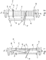
- Fig. 1 shows the braiding bobbin 10 according to the invention in an exemplary embodiment.
- the braiding bobbin 10 serves as a braiding bobbin 10 for a braiding device 12, as exemplarily shown on Fig. 5 .
- the braiding bobbin 10 comprises a cylindrical braiding spool 14.
- a multilayer ribbon 16 may be wound onto the braiding spool 14.
- the multilayer ribbon 16 may be unwound from the braiding spool 14.
- a first layer of the multilayer ribbon 16 is formed by a pre-impregnated fiber film 18.
- a second layer of the multilayer ribbon 16 is formed by a protective film 20.
- the braiding bobbin 10 also comprises a bracket 22.
- the braiding spool 14 is frontally and rotatably fastened to the bracket 22.
- the braiding bobbin 10 comprises a cylindrical additional spool 24 for winding the protective film 20. Therefore, the additional spool 24 is used to wind the protective film 20 of the unwound ribbon 16.
- the braiding bobbin 10 comprises a deflection element 26, wherein the deflection element 26 is fastened to the bracket 22.
- the deflection element 26 is fastened spaced apart relative to the braiding spool 14 in the radial direction R, e.g., as shown on Fig. 2 .
- the deflection element 26 is designed to deflect the protective film 20 from the braiding spool 14 to the additional spool 24.
- the bracket 22 may be designed as a base plate and/or base element.
- a bearing may be provided between the bracket 22 and braiding spool 14 in order to rotatably fasten the braiding spool 14 to the bracket 22.
- the braiding spool 14 may perform a rotation around an accompanying braiding spool rotational axis F relative to the bracket 22.
- the braiding spool 14 is preferably designed symmetrically to the braiding spool rotational axis F. Therefore, the braiding spool 14 may be designed as a cylindrical body, in particular as a circularly cylindrical body. However, the term "cylindrical" is not to be limited to a circularly cylindrical design of the braiding spool 14. Rather, the braiding spool 14 may comprise an annular cross sectional configuration.
- the multilayer ribbon 16 may be wound onto the braiding spool 14.
- the multilayer ribbon 16 may comprise an upper layer and a lower layer, wherein one of the two layers may be the pre-impregnated fiber film 18, and the other layer may be the protective film 20. Additional layers may be provided for the multilayer ribbon 16.
- a tensile force acts on an outer end of the ribbon 16, the latter may be unwound from the braiding spool 14.
- the tensile force here preferably acts on the pre-impregnated fiber film 18.
- the tensile force is caused by the braiding device 12 shown on Fig. 5 , wherein the pre-impregnated fiber film 18 is braided onto the mandrel to be braided 28.
- the tensile force acting on the pre-impregnated fiber film 18 causes the multilayer fiber ribbon 16 to unwind, so that the protective film 20 is also unwound.
- the pre-impregnated fiber film 18 unwound from the braiding spool 14 is guided to the mandrel 28, so as to there braid the mandrel 28, with the protective film 20 not being used to braid the mandrel 28.
- the purpose of the protective film 20 is to ensure that the windings of the pre-impregnated fiber film 18, if still wound onto the braiding spool 14 with the multilayer ribbon 16, only come into contact with each other slightly, or not at all. This is because the pre-impregnated fiber film 18 preferably has a "sticky" surface.
- the protective film 20 is used to prevent the windings of the pre-impregnated fiber film 18, if situated on the braiding spool 14 as the result of the wound ribbon 16, from sticking together.
- the protective film 20 is preferably formed of a thin layer film.
- the protective film 20 is further preferably made out of plastic.
- the protective film 20 comprises such a low surface roughness that the fiber film 18 may be separated and/or peeled from the protective film 20 in essentially a nondestructive manner.
- the braiding bobbin 10 comprises a cylindrical additional spool 24.
- the additional spool 24 is used to wind the protective film 20, here specifically as the portion of the multilayer ribbon 16 that is unwound.
- the braiding spool 14 and additional spool 24 be arranged one behind the other in an axial direction A of the braiding spool 14.
- the braiding spool 14 and additional spool 24 may be aligned coaxially relative to each other. They may thus comprise a shared axial alignment.
- the braiding spool rotational axis F of the braiding spool 14 and an additional spool rotational axis Z of the additional spool 24 are especially preferably aligned coaxially relative to each other.
- the protective film 20 also thereby unwound is deflected toward the additional spool 24 by means of the deflection element 26.
- One end of the deflection element 26 is fastened to the bracket 22.
- the deflection element 26 is preferably designed as a rod-shaped body.
- the deflection element 26 is spaced apart in the radial direction R from the braiding spool 14 and/or additional spool 24.
- the deflection element 26 extends in axial direction A from the bracket 22 up to an area parallel to the additional spool 24.
- the protective film 20 is directed from the braiding spool 14 to the additional spool 24 over an area of the deflection element 26 facing away from the braiding spool 14 and/or additional spool 24.
- the unwound protective film 20 that was deflected by the deflection element 26 is wound by the additional spool 24.
- the additional spool 24 be coupled to the braiding spool 14 in such a way that a rotation by the braiding spool 14 around the accompanying braiding spool rotational axis F triggers a rotation by the additional spool 24 around the accompanying additional spool rotational axis Z.
- the braiding spool 14 rotates clockwise around the accompanying braiding spool rotational axis F, as schematically denoted on Fig.
- the additional spool 24 may resultantly also rotate clockwise around the accompanying additional spool rotational axis Z, as denoted by the rotation arrow above the additional spool 24.
- a rotation by the braiding spool 14 may basically also lead to an opposite rotation by the additional spool 24.
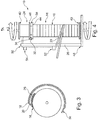
- FIG. 2 An exemplary coupling of the additional spool 24 to the braiding spool 14 is schematically shown on Fig. 2 .
- coupling may be accomplished by means of a connecting element 30, which extends from a front side 32 of the braiding spool 14 to an oppositely situated front side 34 of the additional spool 24.
- the at least one connecting element 30 may be used to establish a mechanical coupling between the braiding spool 14 and additional spool 24. If the braiding spool 14 is now made to rotate by the tensile force acting on the fiber film 18, the braiding spool 14 simultaneously drives the additional spool 24. This configuration ensures that the protective film 20 will always be wound up when the multilayer ribbon 16 or pre-impregnated fiber film 18 starts to be unwound.
- Another advantageous embodiment of the braiding bobbin 10 is characterized in that the front side 32 of the braiding spool 14 is connected with the front side 34 of the additional spool 24, in particular directly.
- the front side 32 of the braiding spool 14 may be joined with the front side 34 of the additional spool 24 materially, non-positively (force fit) and/or positively (form fit).
- the braiding spool 14 and additional spool 24 have an integral and/or one-piece design.
- Fig. 3 presents a side view along a transverse axis of the braiding bobbin 10.
- the protective film 20 is guided by the deflection element 26 while unwinding the multilayer ribbon 16.
- the fiber film 18 also unwound while unwinding the multilayer ribbon 16 is guided away from the braiding spool 14 by a fiber guiding element 36, in particular partially toward the mandrel.
- the fiber guiding element 36 is situated radially outside relative to the deflection element 26.
- the deflection element 26 is also depicted on Fig. 3 . The latter also directs the protective film 20 away from the braiding spool 14 while peeling off the multilayer ribbon 16, so as to divert it toward the additional spool 24.
- the braiding bobbin 10 here comprises a driving means 38.
- the additional spool 24 is coupled with the braiding spool 14 by means of the at least one driving means 38, which is only schematically shown on Fig. 4 , so that a rotation by the braiding spool 14 around the accompanying braiding spool rotational axis F by means of the at least one driving means 38 causes the additional spool 24 to rotate around the accompanying additional spool rotational axis Z.
- the driving means 38 may be a simple transmission.
- the braiding spool 14 may be driven by the additional spool 24. If the braiding spool 14 is made to rotate, the transmission also causes the additional spool 24 to rotate.
- the rotational directions may correspond to each other or be opposite each other.
- a driving means may be designed as a sliding clutch.
- the sliding clutch offers the advantage of being able to limit a tensile force on the protective film 20, which may be exerted by the additional spool 24 on the protective film 20. As a result, a tearing of the protective film 20 may be effectively prevented.
- the braiding spool 14 may comprise a radially outwardly protruding braiding spool limiting disk 44 on one or all of its front sides 32 or 40.
- the at least one braiding spool limiting disk 44 may ensure a reliable unwinding of the multilayer ribbon 16 or the fiber film 18 and the protective film 20, respectively.
- the additional spool 24 may comprise a radially outwardly protruding additional spool limiting disk 46 on at least one or each of its front faces 34, 42.
- the at least one frontal additional spool limiting disk 46 may ensure that the protective film 20 is reliably wound onto the additional spool 24.
- the deflection element 26 extend in an axial direction A from a first deflection element end 48 to a second deflection element end 50, wherein the first deflection element 48 is situated radially outside relative to the braiding spool 14 or on the bracket 22, and the second deflection element end 50 is situated radially outside relative to the additional spool 24. It is here possible that the deflection element 26 not extend over the entire length of the braiding bobbin 10. For example, the deflection element 26 may extend in an axial direction up to an outer third of the additional spool 24 facing away from the braiding spool 14.
- the deflection element 26 may comprise at least one first guiding element 52 and/or at least one additional, in particular the second, guiding element 54.
- the first and/or second guiding element 52, 54 may be formed and/or fastened to an in particular rod-shaped base body of the deflection element 26.
- the deflection element 26 preferably comprises the first guiding element 52 protruding in a radial direction for guiding the protective film 20.
- the first guiding element 52 may absorb forces caused from the protective film 20 in the axial direction A.
- the first guiding element 52 is designed as a deflection pin or deflection roller.
- the deflection element 26 may comprise the second guiding element 54 protruding in a radial direction R for guiding the protective film 20.
- Protruding in the radial direction R may mean that the corresponding guiding element 52, 54 protrudes over a base element of the deflection element 26 in a radial direction R.
- the second guiding element 54 may also be designed as a deflection pin or deflection roller. Therefore, the second guiding element 54 may also absorb forces in the axial direction A.
- the first guiding element 52 and/or the second guiding element 54 may thus be designed to deflect the protective film 20 from a direction of movement in the radial direction R or inclined thereto into an axial direction A or inclined thereto, or vice versa.
- the first guiding element 52 and/or second guiding element 54 may ensure a reliable deflection of the protective film 20 from the braiding spool 14 to the additional spool 24. This is because a deflection element 26 that comprises the first guiding element 52 and/or the second guiding element 54 may reliably guide the protective film 20 from an area of the braiding spool 14 into an area of the additional spool 24.
- the first guiding element 52 it has been found of especially advantage for the first guiding element 52 to be situated in the axial direction centrally and/or relative to a central section of the braiding spool 14.
- the second guiding element 54 it has been found of advantage for the second guiding element 54 to be situated in the axial direction A centrally or relative to a central section of the additional spool 24.
- the protective film 20 may be deflected without a too high tensile stress causing from the braiding spool 14, so that the protective film 20 may be directed or guided to the second guiding element 54 or directly to the additional spool 24.
- Arranging the second guiding element 54 in an axial direction A centrally or relative to a central section of the additional spool 24 has been found of advantage, since the protective film 20 may be wound onto the additional spool 24 without a too high stress.
- a braiding device 12 may be gleaned at least partially and schematically from Fig. 5 .
- the braiding device 12 is used for braiding the mandrel 28 with the pre-impregnated fiber film 18.
- the braiding device 12 comprises a hollow cylindrical module carrier 56.
- a plurality of impellers 58 shown in a simplified manner as circular elements are here provided, which are situated one behind the other on the module carrier 56 in the circumferential direction U of the module carrier 56, wherein each impeller 58 is designed to hold a braiding bobbin 10 and transfer the braiding bobbin 10 to an adjacent impeller 58.
- Also provided for the braiding device 12 is a plurality of braiding bobbins 10 according to the invention.
- the braiding bobbins 10 may be held by the impellers 58 and transferred from impeller to impeller in the circumferential direction U of the module carrier 56.
- the impellers 58 are preferably arranged on the jacket interior. Alternatively or additionally, the impellers may also be situated axially outside on the module carrier 56.
- the respective fiber films 18 from the accompanying braiding spools 14 may be braided onto the mandrel 28, wherein the mandrel 28 is transported through the hollow cylindrical opening 60 in the feeding direction V.
- the fiber films 18 intersect each other on the surface of the mandrel 28, so that the latter is braided with pre-impregnated fiber film 18.
- each impeller 58 comprise a motorized impeller 58 rotatably mounted to the module carrier 56, with a jacket-side area for receiving, holding and dispensing one of the braiding bobbins 10.
Landscapes
- Engineering & Computer Science (AREA)
- Textile Engineering (AREA)
- Manufacturing & Machinery (AREA)
- Braiding, Manufacturing Of Bobbin-Net Or Lace, And Manufacturing Of Nets By Knotting (AREA)
Abstract
Description
- The invention relates to a braiding bobbin for a braiding device, comprising a cylindrical braiding spool, from which a previously wound, multilayer ribbon can be unwound, wherein a first layer of the ribbon consists of a pre-impregnated fiber film, and a second layer of the ribbon consists of a protective film, and a bracket to which the braiding spool is frontally and rotatably fastened.
- In addition, the invention relates to a braiding device for braiding a mandrel with a pre-impregnated fiber film, comprising a hollow cylindrical module carrier, a plurality of impellers, which are arranged one behind the other on the module carrier in the circumferential direction of the modular carrier, wherein each impeller is designed to hold a braiding bobbin and transfer the braiding bobbin to an adjacent impeller, and a plurality of braiding bobbins, which are held by the impellers and may be transferred from impeller to impeller in the circumferential direction of the module carrier.
- Braiding devices are used to braid a mandrel. The mandrel may here consist of a plastic mandrel or mandrel designed in some other way. The mandrel is to be braided with a pre-impregnated fiber film, thereby yielding a fiber composite component. In order to fix the shape of the fiber composite component, the latter may be cured in a subsequent procedural step.
- A hollow cylindrical module carrier is provided for the braiding device. For braiding purposes, the mandrel may be pushed through a hollow cylindrical opening of the module carrier, so that the fiber film may be braided while pushed onto the mandrel.
- Also provided for the braiding device is a plurality of impellers, which are arranged on the module carrier one behind the other in the circumferential direction of the module carrier. The impellers may here be situated radially inwardly on the module carrier and/or in an axial direction frontally on the module carrier. Each impeller is used to hold a braiding bobbin. In addition, the impellers are designed to transfer a respective braiding bobbin to an adjacent impeller. Therefore, if a braiding bobbin is transferred from one impeller to the next impeller, the braiding bobbin wanders from impeller to impeller in the circumferential direction of the module carrier.
- Also provided is a plurality of braiding bobbins for the braiding device, which may be held by the impellers and transferred from impeller to impeller in the circumferential direction of the module carrier. Therefore, the braiding bobbins may be distributed in the circumferential direction of the module carrier, wherein the braiding bobbins are transferred between adjacent impellers. It may here preferably be provided that the braiding bobbins be transferred in a shared circumferential direction of the module carrier. In this way, the plurality of braiding bobbins wanders in the circumferential direction of the module carrier. It may also be provided that the impellers be designed to transfer the braiding bobbins from impeller to impeller through rotation. This enables a braiding of pre-impregnated fiber films, wherein a respective one of them from a respective one of the braiding bobbins is wound on beforehand, and may be unwound with the rotation of the braiding bobbins, so as to braid the mandrel.
- It has been found of advantage for braiding a mandrel to use a pre-impregnated fiber film. For example, this may be a so-called prepreg material or some other semi-finished product with fibers impregnated by a resin. The fibers of the fiber films are carbon fibers and/or glass fibers and/or aramid fibers, for example. A resin based on epoxides and/or a vinyl ester may be provided for impregnation. The pre-impregnated fiber film may comprise an exterior adhesiveness. In particular, the pre-impregnated fiber film may be at least partially uncured and/or be designed as a semi-finished product. For example, the pre-impregnated fiber film may comprise a resin, which may be configured to automatically adhere to other materials.
- In order to prevent the pre-impregnated fiber film from becoming cured already before the mandrel is braided and/or to prevent the windings of the pre-impregnated fiber film on the braiding spool from adhering to each other, it is provided that the fiber film may be or is wound on the cylindrical braiding spool as a layer of the multilayer ribbon. Another layer of the multilayer ribbon is comprised of a protective film. The protective film is here preferably designed in such a way that the pre-impregnated fiber film only comprises a slight adhesive effect relative to the protective film. In particular, the adhesive effect between the fiber film and protective film is less than a dimensional stability of the pre-impregnated fiber film. As a consequence, the protective film may be designed in such a way that the pre-impregnated fiber film may be non-destructively peeled from the protective film.
- Also provided for the braiding bobbin is a bracket, to which the braiding spool is frontally and rotatably fastened. The braiding spool may thus be rotatably fastened to the bracket with a front side allocated thereto. This allows the braiding spool to rotate around an accompanying longitudinal axis relative to the bracket.
- Known from publication
EP 2 905 366 A1 is a braiding device along with a braiding bobbin. - During the practical application of a braiding bobbin on which a multilayer ribbon is wound, wherein a first layer of the ribbon consists of a pre-impregnated fiber film and a second layer of the ribbon consists of a protective film, it was determined that careless operation could result in the problem of the protective film getting into the area of the mandrel, where the protective film is then braided together with the pre-impregnated fiber film in an undefined manner on the mandrel. However, the protective film is not used to form the fiber composite component.
- Therefore, the object of the invention is to propose a braiding bobbin and a braiding device that prevent the protective film from being braided onto the mandrel along with the pre-impregnated fiber film.
- According to a first aspect of the invention, the aforementioned object is solved with a braiding bobbin having the features in claim 1. Therefore provided is a braiding bobbin for a braiding device, comprising: A cylindrical braiding spool, from which a previously wound, multilayer ribbon may be unwound, wherein a first layer of the ribbon consists of a pre-impregnated fiber film and a second layer of the ribbon consists of a protective film, a bracket to which the braiding spool is frontally and rotatably fastened, a cylindrical additional spool for winding the protective film of the unwound ribbon, and a deflection element fastened to the bracket, wherein the deflection element is secured spaced apart in the radial direction to the braiding spool and designed for deflecting the protective film from the braiding spool to the additional spool.
- The advantage to the braiding bobbin owing to the additional spool and deflection element is that the protective film may be directly wound again by the braiding bobbin or additional spool while unwinding the multilayer ribbon. As a result, the braiding bobbin with the additional spool and deflection element ensures that the protective film may be kept away from a mandrel to be braided with the pre-impregnated fiber film, which is also unwound while unwinding the multilayer ribbon. To this end, the protective film may be guided and/or directed toward the additional spool over a side of the deflection element facing away from the braiding spool, so that a separation may be created between the pre-impregnated fiber film and protective film while unwinding the multilayer ribbon, wherein the pre-impregnated fiber film may be guided to the mandrel to braid the latter, and wherein the protective film may be directed by the deflection element to the additional spool. This separation of the protective film from the pre-impregnated fiber film in (especially direct) proximity to the braiding spool and/or additional spool makes it possible to guide the pre-impregnated fiber film for braiding the mandrel free of the protective film while unwinding the multilayer ribbon.
- The braiding spool and/or additional spool are preferably designed as cylindrical bodies. Such a body may comprise a cylindrical jacket wall, onto which the multilayer ribbon or protective film may be wound. The term "cylindrical" is preferably not limited to a circular-cylindrical shape. For example, the braiding spool and/or additional spool may have a circular, oval, or polygonal cross section, and/or some other annular shape. In addition, the braiding spool and/or additional spool may comprise a constant diameter in the axial direction, or a varying diameter in the axial direction. For example, the braiding spool and/or additional spool may comprise a straight outer contour or curved outer contour in a longitudinal section. In particular, the braiding spool and/or additional spool may be conical in design.
- In an example, the pre-impregnated fiber film may be designed as a pre-impregnated fiber-band, a pre-impregnated fiber tape or a pre-impregnated fiber-ribbon.
- The bracket is preferably designed to have the braiding spool rotatably mounted thereto. In addition, the deflection element is fastened to the bracket. The deflection element is preferably rigidly joined with the bracket. In this way, the deflection element and bracket may be configured as an integral component. In addition, it may be provided that the bracket be designed as a base plate.
- One advantageous embodiment of the braiding bobbin is characterized in that the additional spool is coupled to the braiding spool in such a way that a rotation by the braiding spool around an accompanying braiding spool rotational axis causes the additional spool to rotate around an accompanying additional spool rotational axis. Coupling the additional spool to the braiding spool ensures that the additional spool may be driven around the accompanying additional spool rotational axis. The coupling may here be designed as a mechanical coupling.
- Braiding a mandrel allows a tensile force to act on the pre-impregnated fiber film in the direction of the mandrel. The latter makes it possible to initiate an unwinding of the multilayer ribbon from the braiding spool, thereby causing the braiding spool to rotate around the accompanying braiding spool rotational axis. In other words, braiding the mandrel makes it possible to remove or unwind the pre-impregnated fiber film from the braiding spool. This triggers the aforementioned rotation by the braiding spool around the accompanying braiding spool rotational axis. Due to the preferred coupling between the braiding spool and additional spool, the additional spool may be made to rotate around the accompanying rotational spool rotational axis, thereby causing the protective film to be wound. Therefore, coupling the additional spool to the braiding spool may ensure that the additional spool is always made to rotate around the accompanying additional spool rotational axis if the braiding spool also rotates around the accompanying braiding spool rotational axis. In this way, the protective film is effectively kept away from the mandrel, which prevents the mandrel from also being inadvertently co-braided by the protective film.
- A preferred embodiment of the braiding bobbin is characterized in that the braiding spool and additional spool are arranged one behind the other in an axial direction of the braiding spool. This configuration of the braiding bobbin offers the advantage that the braiding bobbin may comprise an especially small surface area. As a result, an especially high number of braiding bobbins may be held by the impellers or transferred from impeller to impeller in the circumferential direction of a modular carrier of the braiding device.
- It has been found of advantageous for a front side of the braiding spool to be situated parallel opposite a front side of the additional spool. Such a configuration enables an especially compact structural design for the braiding bobbin.
- Another advantageous embodiment of the braiding bobbin is characterized in that a first front side of the braiding spool is joined with a first front side of the additional spool. Such a configuration of the braiding bobbin is especially compact. The first front side of the braiding spool may be materially, non-positively (force fit) and/or positively (form fit) joined with the first front side of the additional spool. The first front side of the braiding spool and the first front side of the additional spool may here be front sides facing each other.
- In another example, it may be provided that the braiding spool and the additional spool have an integral and/or one-piece design. Such an embodiment of the braiding bobbin is also especially compact, and may comprise a high dimensional stability.
- Another advantageous embodiment of the braiding bobbin is characterized in that the first front side of the braiding spool is separate from the first front side of the additional spool. This embodiment of the braiding bobbin makes it possible to change out the respective braiding spool and/or additional spool decoupled from each other. In addition, such an embodiment allows the braiding spool and additional spool to rotate in different directions.
- Another advantageous embodiment of the braiding bobbin is characterized in that the braiding spool and additional spool are aligned coaxially or with axial directions aligned parallel to each other. The axial direction of the braiding spool may be determined by the accompanying braiding spool rotational axis. The axial direction of the additional spool may be determined by the accompanying additional spool rotational axis.
- The additional spool rotational axis of the additional spool may be spaced apart in a radial direction from the braiding spool rotational axis of the braiding spool. The two rotational axes may here be aligned parallel to each other.
- Given a coaxial alignment of the additional spool to the braiding spool, the latter may comprise a shared rotational axis.
- Another example may provide that the braiding spool and additional spool be situated at an angle deviating from 0° relative to each other. For example, it may be provided that the additional spool rotational axis of the additional spool be arranged at an angle of between 30° and 120°, preferably of 90°, relative to the braiding spool rotational axis of the braiding spool.
- Another advantageous embodiment of the braiding bobbin is characterized in that the additional spool is coupled with the braiding spool by at least one driving means, so that rotating the braiding spool around the accompanying braiding spool rotational axis by means of the at least one driving means causes the additional spool to rotate around the accompanying additional spool rotational axis. This embodiment of the braiding bobbin offers the advantage that the additional spool may be driven by the braiding spool, so that a rotation of the braiding spool causes a rotation of the additional spool.
- For example, a transmission may be provided as the driving means. The transmission may comprise a transmission ratio of 1, a transmission ratio of less than 1 or a transmission ratio of greater than 1. The transmission offers the advantage that a ratio between the rotational speed of the braiding spool and a rotational speed of the additional spool may be determined or set. For example, if the additional spool comprises a smaller diameter than the braiding spool, the transmission may be designed in such a way that a rotation of the braiding spool at a specific rotational speed leads to a rotation of the additional spool at a higher rotational speed.
- The or one of the driving means may also be comprised of a sliding clutch. The sliding clutch offers the advantage that a protective film that has been unwound but not yet wound onto the additional spool will not tear. For example, if a high tensile stress acts on the protective film, the sliding clutch may slip through, so that the sliding clutch may be used to limit the tensile stress on the protective film.
- A belt drive may be provided as the or one driving means. As a result of the belt drive, the additional spool need not be situated coaxially to the braiding spool. In addition, the or one of the driving means may be especially simple in design using a belt drive.
- Another advantageous embodiment of the braiding bobbin is characterized in that each front side of the braiding spool comprises a radially outwardly protruding braiding spool limiting disk. The braiding spool limiting disks may ensure a reliable winding and/or unwinding of the multilayer ribbon onto or from the braiding spool, respectively.
- Another advantageous embodiment of the braiding bobbin is characterized in that each front side of the additional spool comprises a radially outwardly protruding additional spool limiting disk. The additional spool limiting disks may ensure a reliable winding of the protective film onto the additional spool.
- If the braiding spool and additional spool are designed as an integral component, a braiding spool limiting disk may be designed integrally with an additional spool limiting disk.
- Another advantageous embodiment of the braiding bobbin is characterized in that the deflection element extends in an axial direction from a first deflection element end to a second deflection element end, wherein the first deflection element end is situated radially outside relative to the braiding spool, and the second deflection element end is situated radially outside relative to the additional spool. In this embodiment, the axial direction preferably refers to the axial direction of the braiding spool, which is preferably determined by the braiding spool rotational axis.
- The deflection element is preferably situated radially outside, in particular parallel, and/or overlapping relative to the braiding spool and additional spool.
- An example may provide that the second deflection element end be arranged radially outside relative to a section of the additional spool that is central in the axial direction. This makes it possible for the deflection element to not extend in an axial direction over the entire length of the braiding bobbin and/or additional spool.
- Because the deflection element may extend from a radially outer area of the braiding spool to a radially outer area of the additional spool, the deflection element may especially reliably divert the protective film from the braiding spool to the additional spool.
- The deflection element may preferably be designed as a rod-shaped body. The rod-shaped body may be fastened at one end to the bracket and/or extend parallel to the braiding spool rotational axis and/or the additional spool rotational axis.
- Another example may provide that the deflection element be formed by an annular body, in particular having an oval and/or circular opening cross section. The protective film may be guided through the opening of such an annular body, so as to ensure a reliable diversion from the braiding spool to the additional spool using such a deflection element.
- Another advantageous embodiment of the braiding bobbin is characterized in that the deflection element comprises a first guiding element protruding in the radial direction for guiding the protective film. The first guiding element of the deflection element offers the advantage that a guiding path for the protective film may be more precisely determined. In an example, the first guiding element may be designed as a deflection pin or deflection roller.
- Another advantageous embodiment of the braiding bobbin is characterized in that the first guiding element is situated centrally in an axial direction relative to the braiding spool. Such an arrangement of the first guiding element makes it possible to deflect the protective film in direct proximity to the braiding spool at the first guiding element, so as to be guided away from the braiding spool. This may provide a stronger guarantee that the protective film will not inadvertently be guided to the mandrel.
- Another advantageous embodiment of the braiding bobbin is characterized in that he deflection element comprises a second guiding element protruding in the radial direction for guiding the protective film.
- The second protruding guiding element may be used to determine a guiding section along which the protective film is to be guided from the braiding spool to the additional spool. In an example, the second guiding element may be designed as a deflection pin or a deflection roller.
- Another advantageous embodiment of the braiding bobbin is characterized in that the second guiding element is situated centrally in the axial direction relative to the additional spool. This arrangement of the second guiding element offers the advantage that the protective film may be specifically directed toward the additional spool.
- According to another aspect of the invention, the object mentioned at the outset may be achieved by a braiding device having the features of
claim 12. Provided for this purpose is a braiding device for braiding a mandrel with a pre-impregnated fiber film, comprising a hollow cylindrical module carrier, a plurality of impellers, which are arranged one behind the other on the module carrier in the circumferential direction of the modular carrier, wherein each impeller is designed to hold a braiding bobbin and transfer the braiding bobbin to an adjacent impeller, and a plurality of braiding bobbins according to the invention, which are held by the impellers and may be transferred from impeller to impeller in the circumferential direction of the module carrier. The braiding bobbins may here preferably be designed based on one of the aforementioned advantageous embodiments or examples. For this reason, the advantages, advantageous embodiments and/or examples discussed for the braiding bobbin apply analogously to the braiding device. - A preferred embodiment of the braiding device is characterized in that each impeller comprises a motorized impeller rotatably mounted to the module carrier, with a jacket-side receiving area for receiving, holding and dispensing one of the braiding bobbins.
- Additional advantageous embodiments of the invention may be gleaned from the description of embodiments according to the invention in conjunction with the claims and/or attached drawings. Embodiments according to the invention may here involve individual features or a combination of several features. The invention will be explained below based on exemplary embodiments with reference to the drawings, without limiting the overall inventive idea. The drawings show:
- Fig. 1
- an exemplary embodiment of the braiding bobbin according to the invention in a first schematic side view,
- Fig. 2
- another exemplary embodiment of the braiding bobbin according to the invention in a schematic side view,
- Fig. 3
- another exemplary embodiment of the braiding bobbin according to the invention in a schematic top view,
- Fig. 4
- another exemplary embodiment of the braiding bobbin according to the invention in a schematic side view, and
- Fig. 5
- an exemplary embodiment of the braiding device according to the invention in a schematic perspective view.
-
Fig. 1 shows thebraiding bobbin 10 according to the invention in an exemplary embodiment. Thebraiding bobbin 10 serves as abraiding bobbin 10 for abraiding device 12, as exemplarily shown onFig. 5 . - The
braiding bobbin 10 comprises acylindrical braiding spool 14. Amultilayer ribbon 16 may be wound onto thebraiding spool 14. In addition, themultilayer ribbon 16 may be unwound from thebraiding spool 14. A first layer of themultilayer ribbon 16 is formed by apre-impregnated fiber film 18. A second layer of themultilayer ribbon 16 is formed by aprotective film 20. - The
braiding bobbin 10 also comprises abracket 22. Thebraiding spool 14 is frontally and rotatably fastened to thebracket 22. - In addition, the
braiding bobbin 10 comprises a cylindricaladditional spool 24 for winding theprotective film 20. Therefore, theadditional spool 24 is used to wind theprotective film 20 of the unwoundribbon 16. - In addition, the
braiding bobbin 10 comprises adeflection element 26, wherein thedeflection element 26 is fastened to thebracket 22. Thedeflection element 26 is fastened spaced apart relative to thebraiding spool 14 in the radial direction R, e.g., as shown onFig. 2 . In addition, thedeflection element 26 is designed to deflect theprotective film 20 from thebraiding spool 14 to theadditional spool 24. - As may be gleaned from
Fig. 1 , thebracket 22 may be designed as a base plate and/or base element. A bearing may be provided between thebracket 22 andbraiding spool 14 in order to rotatably fasten thebraiding spool 14 to thebracket 22. As a consequence, thebraiding spool 14 may perform a rotation around an accompanying braiding spool rotational axis F relative to thebracket 22. - The
braiding spool 14 is preferably designed symmetrically to the braiding spool rotational axis F. Therefore, thebraiding spool 14 may be designed as a cylindrical body, in particular as a circularly cylindrical body. However, the term "cylindrical" is not to be limited to a circularly cylindrical design of thebraiding spool 14. Rather, thebraiding spool 14 may comprise an annular cross sectional configuration. - The
multilayer ribbon 16 may be wound onto thebraiding spool 14. Themultilayer ribbon 16 may comprise an upper layer and a lower layer, wherein one of the two layers may be thepre-impregnated fiber film 18, and the other layer may be theprotective film 20. Additional layers may be provided for themultilayer ribbon 16. - If a tensile force acts on an outer end of the
ribbon 16, the latter may be unwound from thebraiding spool 14. The tensile force here preferably acts on thepre-impregnated fiber film 18. The tensile force is caused by thebraiding device 12 shown onFig. 5 , wherein thepre-impregnated fiber film 18 is braided onto the mandrel to be braided 28. - The tensile force acting on the
pre-impregnated fiber film 18 causes themultilayer fiber ribbon 16 to unwind, so that theprotective film 20 is also unwound. Thepre-impregnated fiber film 18 unwound from thebraiding spool 14 is guided to themandrel 28, so as to there braid themandrel 28, with theprotective film 20 not being used to braid themandrel 28. The purpose of theprotective film 20 is to ensure that the windings of thepre-impregnated fiber film 18, if still wound onto thebraiding spool 14 with themultilayer ribbon 16, only come into contact with each other slightly, or not at all. This is because thepre-impregnated fiber film 18 preferably has a "sticky" surface. Therefore, theprotective film 20 is used to prevent the windings of thepre-impregnated fiber film 18, if situated on thebraiding spool 14 as the result of thewound ribbon 16, from sticking together. Theprotective film 20 is preferably formed of a thin layer film. Theprotective film 20 is further preferably made out of plastic. In addition, theprotective film 20 comprises such a low surface roughness that thefiber film 18 may be separated and/or peeled from theprotective film 20 in essentially a nondestructive manner. - As already mentioned, the
protective film 20 is not used to braid themandrel 28. In order to keep theprotective film 20 from inadvertently getting in direct proximity to themandrel 28, and to further keep theprotective film 20 from inadvertently also being braided onto the mandrel, thebraiding bobbin 10 comprises a cylindricaladditional spool 24. Theadditional spool 24 is used to wind theprotective film 20, here specifically as the portion of themultilayer ribbon 16 that is unwound. - As may be gleaned from
Fig. 1 and Fig. 2 , it is preferably provided that thebraiding spool 14 andadditional spool 24 be arranged one behind the other in an axial direction A of thebraiding spool 14. In this way, thebraiding spool 14 andadditional spool 24 may be aligned coaxially relative to each other. They may thus comprise a shared axial alignment. The braiding spool rotational axis F of thebraiding spool 14 and an additional spool rotational axis Z of theadditional spool 24 are especially preferably aligned coaxially relative to each other. - If the
multilayer ribbon 16 is unwound in response to the tensile force acting on thepre-impregnated fiber film 18, theprotective film 20 also thereby unwound is deflected toward theadditional spool 24 by means of thedeflection element 26. One end of thedeflection element 26 is fastened to thebracket 22. Thedeflection element 26 is preferably designed as a rod-shaped body. Thedeflection element 26 is spaced apart in the radial direction R from thebraiding spool 14 and/oradditional spool 24. In addition, thedeflection element 26 extends in axial direction A from thebracket 22 up to an area parallel to theadditional spool 24. During deflection, theprotective film 20 is directed from thebraiding spool 14 to theadditional spool 24 over an area of thedeflection element 26 facing away from thebraiding spool 14 and/oradditional spool 24. - The unwound
protective film 20 that was deflected by thedeflection element 26 is wound by theadditional spool 24. To this end, it is preferably provided that theadditional spool 24 be coupled to thebraiding spool 14 in such a way that a rotation by thebraiding spool 14 around the accompanying braiding spool rotational axis F triggers a rotation by theadditional spool 24 around the accompanying additional spool rotational axis Z. For example, if thebraiding spool 14 rotates clockwise around the accompanying braiding spool rotational axis F, as schematically denoted onFig. 1 by the rotation arrow below thebracket 22, theadditional spool 24 may resultantly also rotate clockwise around the accompanying additional spool rotational axis Z, as denoted by the rotation arrow above theadditional spool 24. A rotation by thebraiding spool 14 may basically also lead to an opposite rotation by theadditional spool 24. - An exemplary coupling of the
additional spool 24 to thebraiding spool 14 is schematically shown onFig. 2 . For example, coupling may be accomplished by means of a connectingelement 30, which extends from afront side 32 of thebraiding spool 14 to an oppositely situatedfront side 34 of theadditional spool 24. The at least one connectingelement 30 may be used to establish a mechanical coupling between thebraiding spool 14 andadditional spool 24. If thebraiding spool 14 is now made to rotate by the tensile force acting on thefiber film 18, thebraiding spool 14 simultaneously drives theadditional spool 24. This configuration ensures that theprotective film 20 will always be wound up when themultilayer ribbon 16 orpre-impregnated fiber film 18 starts to be unwound. - Another advantageous embodiment of the
braiding bobbin 10 is characterized in that thefront side 32 of thebraiding spool 14 is connected with thefront side 34 of theadditional spool 24, in particular directly. For example, thefront side 32 of thebraiding spool 14 may be joined with thefront side 34 of theadditional spool 24 materially, non-positively (force fit) and/or positively (form fit). It may further be preferred that thebraiding spool 14 andadditional spool 24 have an integral and/or one-piece design. -
Fig. 3 presents a side view along a transverse axis of thebraiding bobbin 10. As may be taken therefrom, theprotective film 20 is guided by thedeflection element 26 while unwinding themultilayer ribbon 16. Thefiber film 18 also unwound while unwinding themultilayer ribbon 16 is guided away from thebraiding spool 14 by afiber guiding element 36, in particular partially toward the mandrel. Thefiber guiding element 36 is situated radially outside relative to thedeflection element 26. Thedeflection element 26 is also depicted onFig. 3 . The latter also directs theprotective film 20 away from thebraiding spool 14 while peeling off themultilayer ribbon 16, so as to divert it toward theadditional spool 24. - Another embodiment of the
braiding bobbin 10 is shown onFig. 4 . Thebraiding bobbin 10 here comprises a driving means 38. Theadditional spool 24 is coupled with thebraiding spool 14 by means of the at least one driving means 38, which is only schematically shown onFig. 4 , so that a rotation by thebraiding spool 14 around the accompanying braiding spool rotational axis F by means of the at least one driving means 38 causes theadditional spool 24 to rotate around the accompanying additional spool rotational axis Z. For example, the driving means 38 may be a simple transmission. By means of the transmission thebraiding spool 14 may be driven by theadditional spool 24. If thebraiding spool 14 is made to rotate, the transmission also causes theadditional spool 24 to rotate. The rotational directions may correspond to each other or be opposite each other. - Alternatively or additionally, a driving means may be designed as a sliding clutch. The sliding clutch offers the advantage of being able to limit a tensile force on the
protective film 20, which may be exerted by theadditional spool 24 on theprotective film 20. As a result, a tearing of theprotective film 20 may be effectively prevented. - The
braiding spool 14 may comprise a radially outwardly protruding braidingspool limiting disk 44 on one or all of itsfront sides spool limiting disk 44 may ensure a reliable unwinding of themultilayer ribbon 16 or thefiber film 18 and theprotective film 20, respectively. - The
additional spool 24 may comprise a radially outwardly protruding additionalspool limiting disk 46 on at least one or each of its front faces 34, 42. The at least one frontal additionalspool limiting disk 46 may ensure that theprotective film 20 is reliably wound onto theadditional spool 24. - It may also be provided for the
braiding bobbin 10 that thedeflection element 26 extend in an axial direction A from a firstdeflection element end 48 to a seconddeflection element end 50, wherein thefirst deflection element 48 is situated radially outside relative to thebraiding spool 14 or on thebracket 22, and the seconddeflection element end 50 is situated radially outside relative to theadditional spool 24. It is here possible that thedeflection element 26 not extend over the entire length of thebraiding bobbin 10. For example, thedeflection element 26 may extend in an axial direction up to an outer third of theadditional spool 24 facing away from thebraiding spool 14. - As may be taken from
Fig. 1, 2 and4 , thedeflection element 26 may comprise at least onefirst guiding element 52 and/or at least one additional, in particular the second, guidingelement 54. The first and/or second guidingelement deflection element 26. Thedeflection element 26 preferably comprises the first guidingelement 52 protruding in a radial direction for guiding theprotective film 20. As a consequence, the first guidingelement 52 may absorb forces caused from theprotective film 20 in the axial direction A. For example, the first guidingelement 52 is designed as a deflection pin or deflection roller. In addition, thedeflection element 26 may comprise thesecond guiding element 54 protruding in a radial direction R for guiding theprotective film 20. Protruding in the radial direction R may mean that the corresponding guidingelement deflection element 26 in a radial direction R. Thesecond guiding element 54 may also be designed as a deflection pin or deflection roller. Therefore, thesecond guiding element 54 may also absorb forces in the axial direction A. Thefirst guiding element 52 and/or thesecond guiding element 54 may thus be designed to deflect theprotective film 20 from a direction of movement in the radial direction R or inclined thereto into an axial direction A or inclined thereto, or vice versa. Thefirst guiding element 52 and/or second guidingelement 54 may ensure a reliable deflection of theprotective film 20 from thebraiding spool 14 to theadditional spool 24. This is because adeflection element 26 that comprises the first guidingelement 52 and/or thesecond guiding element 54 may reliably guide theprotective film 20 from an area of thebraiding spool 14 into an area of theadditional spool 24. - It has been found of especially advantage for the first guiding
element 52 to be situated in the axial direction centrally and/or relative to a central section of thebraiding spool 14. In addition, it has been found of advantage for thesecond guiding element 54 to be situated in the axial direction A centrally or relative to a central section of theadditional spool 24. In this case, theprotective film 20 may be deflected without a too high tensile stress causing from thebraiding spool 14, so that theprotective film 20 may be directed or guided to thesecond guiding element 54 or directly to theadditional spool 24. Arranging thesecond guiding element 54 in an axial direction A centrally or relative to a central section of theadditional spool 24 has been found of advantage, since theprotective film 20 may be wound onto theadditional spool 24 without a too high stress. - A
braiding device 12 may be gleaned at least partially and schematically fromFig. 5 . Thebraiding device 12 is used for braiding themandrel 28 with thepre-impregnated fiber film 18. Thebraiding device 12 comprises a hollowcylindrical module carrier 56. A plurality ofimpellers 58 shown in a simplified manner as circular elements are here provided, which are situated one behind the other on themodule carrier 56 in the circumferential direction U of themodule carrier 56, wherein eachimpeller 58 is designed to hold abraiding bobbin 10 and transfer thebraiding bobbin 10 to anadjacent impeller 58. Also provided for thebraiding device 12 is a plurality ofbraiding bobbins 10 according to the invention. The braiding bobbins 10 may be held by theimpellers 58 and transferred from impeller to impeller in the circumferential direction U of themodule carrier 56. Theimpellers 58 are preferably arranged on the jacket interior. Alternatively or additionally, the impellers may also be situated axially outside on themodule carrier 56. - By transferring the
braiding bobbins 10 from impeller to impeller, therespective fiber films 18 from the accompanying braiding spools 14 may be braided onto themandrel 28, wherein themandrel 28 is transported through the hollowcylindrical opening 60 in the feeding direction V. In the process, thefiber films 18 intersect each other on the surface of themandrel 28, so that the latter is braided withpre-impregnated fiber film 18. - It is preferably provided for the
braiding device 12 that eachimpeller 58 comprise amotorized impeller 58 rotatably mounted to themodule carrier 56, with a jacket-side area for receiving, holding and dispensing one of thebraiding bobbins 10.
Claims (13)
- A braiding bobbin (10) for a braiding device (12), comprising- a cylindrical braiding spool (14), from which a previously wound, multilayer ribbon (16) can be unwound, wherein a first layer of the ribbon (16) consists of a pre-impregnated fiber film (18) and a second layer of the ribbon consists of a protective film (20), and- a bracket (22) to which the braiding spool (14) is frontally and rotatably fastened,characterized by- a cylindrical additional spool (24) for winding the protective film (20) of the unwound ribbon (16), and- a deflection element (26) fastened to the bracket (22),wherein the deflection element (26) is secured spaced apart in a radial direction R to the braiding spool (14) and designed for deflecting the protective film (20) from the braiding spool (14) to the additional spool (24).
- The braiding bobbin (10) according to the preceding claim, characterized in that the additional spool (24) is coupled to the braiding spool (14) in such a way that a rotation by the braiding spool (14) around an accompanying braiding spool rotational axis F causes the additional spool (24) to rotate around an accompanying additional spool rotational axis Z.
- The braiding bobbin (10) according to one of the preceding claims, characterized in that the braiding spool (14) and additional spool (24) are arranged one behind the other in an axial direction A of the braiding spool (14).
- The braiding bobbin (10) according to one of the preceding claims, characterized in that a first front side (32) of the braiding spool (14) is joined with a first front side (34) of the additional spool (24).
- The braiding bobbin according to one of the preceding claims, characterized in that the braiding spool (14) and additional spool (24) are aligned coaxially or with axial directions aligned parallel to each other.
- The braiding bobbin (10) according to one of the preceding claims, characterized in that the additional spool (24) is coupled with the braiding spool (14) by at least one driving means (38), so that rotating the braiding spool (14) around the accompanying braiding spool (14) rotational axis F by means of the at least one driving means (38) causes the additional spool (14) to rotate around the accompanying additional spool rotational axis Z.
- The braiding bobbin (10) according to one of the preceding claims, characterized in that- each front side (32, 40) of the braiding spool (14) comprises a radially outwardly protruding braiding spool limiting disk (44), and/or- each front side (34, 42) of the additional spool (24) comprises a radially outwardly protruding additional spool limiting disk (46).
- The braiding bobbin (10) according to the preceding claim, characterized in that the deflection element (26) extends in an axial direction A from a first deflection element end (48) to a second deflection element end (50), wherein the first deflection element end (48) is situated radially outside relative to the braiding spool (14), and the second deflection element end (50) is situated radially outside relative to the additional spool (24).
- The braiding bobbin (10) according to the preceding claim, characterized in that the deflection element (26) comprises a first guiding element (52) protruding in the radial direction R for guiding the protective film (20).
- The braiding bobbin (10) according to the preceding claim, characterized in that the deflection element (26) comprises a second guiding element (54) protruding in the radial direction R for guiding the protective film (20).
- The braiding bobbin (10) according to one of the preceding claims 9 to 10, characterized in that
the first guiding element (52) is situated in the axial direction A centrally relative to the braiding spool (14), and/or that
the second guiding element (54) is situated in the axial direction A centrally relative to the additional spool (24). - A braiding device (12) for braiding a mandrel (28) with a pre-impregnated fiber film (18), comprising:- a hollow cylindrical module carrier (56),- a plurality of impellers (58) situated one behind the other on the module carrier (56) in the circumferential direction U of the module carrier (56), wherein each impeller (58) is designed to hold a braiding bobbin (10) and transfer the braiding bobbin (10) to an adjacent impeller (58), and- a plurality of braiding bobbins (10), which can be held by the impellers (58) and transferred from impeller to impeller in the circumferential direction U of the module carrier (56),characterized in that- the braiding bobbins (10) are each designed according to one of the preceding claims 1 to 11.
- The braiding device (12) according to the preceding claim, characterized in that each impeller (58) comprises a motorized impeller (58) rotatably mounted to the module carrier (56), with a jacket-side area for receiving, holding and dispensing one of the braiding bobbins (10).
Applications Claiming Priority (1)
| Application Number | Priority Date | Filing Date | Title |
|---|---|---|---|
| DE102015119682.4A DE102015119682A1 (en) | 2015-11-13 | 2015-11-13 | Wicker bobbin and braiding device |
Publications (2)
| Publication Number | Publication Date |
|---|---|
| EP3170931A1 true EP3170931A1 (en) | 2017-05-24 |
| EP3170931B1 EP3170931B1 (en) | 2021-08-04 |
Family
ID=57321170
Family Applications (1)
| Application Number | Title | Priority Date | Filing Date |
|---|---|---|---|
| EP16198635.1A Active EP3170931B1 (en) | 2015-11-13 | 2016-11-14 | Braiding bobbin and braiding device |
Country Status (3)
| Country | Link |
|---|---|
| US (1) | US10563329B2 (en) |
| EP (1) | EP3170931B1 (en) |
| DE (1) | DE102015119682A1 (en) |
Citations (3)
| Publication number | Priority date | Publication date | Assignee | Title |
|---|---|---|---|---|
| US6450078B1 (en) * | 2000-10-31 | 2002-09-17 | Federal-Mogul Systems Protection Group, Inc. | Thermal gaskets and method and apparatus for producing the same |
| EP2479327A1 (en) * | 2011-01-20 | 2012-07-25 | Tape Weaving Sweden AB | Textile materials comprising tapes in two oblique orientations and composite materials comprising such materials |
| EP2905366A1 (en) | 2014-02-06 | 2015-08-12 | Airbus Defence and Space GmbH | Modular element for powering and holding braiding lace and braiding device |
Family Cites Families (8)
| Publication number | Priority date | Publication date | Assignee | Title |
|---|---|---|---|---|
| US1358173A (en) * | 1919-09-13 | 1920-11-09 | Nat Indicator Company | Braiding-machine |
| US2653506A (en) * | 1950-10-03 | 1953-09-29 | Fraser Robert Martin | Braiding machine |
| US2897715A (en) * | 1957-05-06 | 1959-08-04 | Wanskuck Co | Braider carrier |
| US4788898A (en) * | 1987-12-18 | 1988-12-06 | Karg Corporation | Control for a bobbin carrier |
| DE10254288A1 (en) * | 2002-11-20 | 2004-06-03 | Tesa Ag | Device for unrolling a web of carrier material located on a roll, in particular with adhesive tape sections provided with adhesive on both sides |
| US20070251647A1 (en) * | 2006-04-26 | 2007-11-01 | Harrison Huang | Manual label dispenser |
| DE102007054645A1 (en) * | 2007-11-15 | 2009-05-28 | Airbus Deutschland Gmbh | Apparatus and method for producing a fiber composite component |
| US20140087198A1 (en) * | 2012-09-26 | 2014-03-27 | Web Industries, Inc. | Prepreg tape slitting method and apparatus |
-
2015
- 2015-11-13 DE DE102015119682.4A patent/DE102015119682A1/en not_active Withdrawn
-
2016
- 2016-11-11 US US15/349,574 patent/US10563329B2/en active Active
- 2016-11-14 EP EP16198635.1A patent/EP3170931B1/en active Active
Patent Citations (3)
| Publication number | Priority date | Publication date | Assignee | Title |
|---|---|---|---|---|
| US6450078B1 (en) * | 2000-10-31 | 2002-09-17 | Federal-Mogul Systems Protection Group, Inc. | Thermal gaskets and method and apparatus for producing the same |
| EP2479327A1 (en) * | 2011-01-20 | 2012-07-25 | Tape Weaving Sweden AB | Textile materials comprising tapes in two oblique orientations and composite materials comprising such materials |
| EP2905366A1 (en) | 2014-02-06 | 2015-08-12 | Airbus Defence and Space GmbH | Modular element for powering and holding braiding lace and braiding device |
Also Published As
| Publication number | Publication date |
|---|---|
| DE102015119682A1 (en) | 2017-05-18 |
| US20170137979A1 (en) | 2017-05-18 |
| US10563329B2 (en) | 2020-02-18 |
| EP3170931B1 (en) | 2021-08-04 |
Similar Documents
| Publication | Publication Date | Title |
|---|---|---|
| KR102406876B1 (en) | winder | |
| US7975591B2 (en) | Braiding bobbin, braiding machine and method for drawing off a fiber from the spool of a braiding bobbin | |
| US12252374B2 (en) | Reeling device | |
| WO2017154297A1 (en) | Method and device for manufacturing optical fiber ribbon | |
| US5044573A (en) | Rotating drum filament dispenser | |
| SE462878B (en) | twisting machine | |
| EP3655232B1 (en) | Tape application device for helical application of a tape on a tube | |
| EP3170931B1 (en) | Braiding bobbin and braiding device | |
| EP2444345A1 (en) | Machine for winding pairs of tubes parallel to an advancing direction and independent of each other | |
| US6832981B2 (en) | Tube arrangement and a method for its manufacture | |
| KR930021879A (en) | Manufacturing method and apparatus of steel wire rope | |
| JP5876158B2 (en) | Device comprising a rotating arm for unwinding a strand of material | |
| TWI548583B (en) | Tape supply device | |
| NL8802981A (en) | WIRE DISCONNECTING DEVICE AND SIMILAR DEVICES INCLUDING DISTRIBUTION DEVICE. | |
| EP1693126A1 (en) | Device for dispensing two or more twisted wires | |
| CN112897234B (en) | A winding device for guiding optical fiber package | |
| CN101384499B (en) | Device for guiding a thread and winding machine | |
| US3301506A (en) | Yarn package | |
| CN1323020C (en) | Device for catching the wire at the beginning of the winding process | |
| US9611585B2 (en) | Method and apparatus for curing of pre impregnated synthetic components in situ | |
| EP0042248A2 (en) | Manufacture of composite shafts | |
| JP4429792B2 (en) | Hose wire winding device | |
| KR20190034098A (en) | Needle winding device and needle winding method | |
| JP2014080289A (en) | Traverse drum, yarn winder, and method of manufacturing traverse drum | |
| CN112439818B (en) | A device for quickly installing spiral casing |
Legal Events
| Date | Code | Title | Description |
|---|---|---|---|
| PUAI | Public reference made under article 153(3) epc to a published international application that has entered the european phase |
Free format text: ORIGINAL CODE: 0009012 |
|
| STAA | Information on the status of an ep patent application or granted ep patent |
Free format text: STATUS: THE APPLICATION HAS BEEN PUBLISHED |
|
| AK | Designated contracting states |
Kind code of ref document: A1 Designated state(s): AL AT BE BG CH CY CZ DE DK EE ES FI FR GB GR HR HU IE IS IT LI LT LU LV MC MK MT NL NO PL PT RO RS SE SI SK SM TR |
|
| AX | Request for extension of the european patent |
Extension state: BA ME |
|
| STAA | Information on the status of an ep patent application or granted ep patent |
Free format text: STATUS: REQUEST FOR EXAMINATION WAS MADE |
|
| 17P | Request for examination filed |
Effective date: 20170713 |
|
| RBV | Designated contracting states (corrected) |
Designated state(s): AL AT BE BG CH CY CZ DE DK EE ES FI FR GB GR HR HU IE IS IT LI LT LU LV MC MK MT NL NO PL PT RO RS SE SI SK SM TR |
|
| GRAP | Despatch of communication of intention to grant a patent |
Free format text: ORIGINAL CODE: EPIDOSNIGR1 |
|
| STAA | Information on the status of an ep patent application or granted ep patent |
Free format text: STATUS: GRANT OF PATENT IS INTENDED |
|
| RIC1 | Information provided on ipc code assigned before grant |
Ipc: D04C 3/18 20060101AFI20210412BHEP Ipc: D04C 1/02 20060101ALN20210412BHEP |
|
| INTG | Intention to grant announced |
Effective date: 20210514 |
|
| INTG | Intention to grant announced |
Effective date: 20210514 |
|
| GRAS | Grant fee paid |
Free format text: ORIGINAL CODE: EPIDOSNIGR3 |
|
| GRAA | (expected) grant |
Free format text: ORIGINAL CODE: 0009210 |
|
| STAA | Information on the status of an ep patent application or granted ep patent |
Free format text: STATUS: THE PATENT HAS BEEN GRANTED |
|
| AK | Designated contracting states |
Kind code of ref document: B1 Designated state(s): AL AT BE BG CH CY CZ DE DK EE ES FI FR GB GR HR HU IE IS IT LI LT LU LV MC MK MT NL NO PL PT RO RS SE SI SK SM TR |
|
| REG | Reference to a national code |
Ref country code: GB Ref legal event code: FG4D |
|
| REG | Reference to a national code |
Ref country code: AT Ref legal event code: REF Ref document number: 1417087 Country of ref document: AT Kind code of ref document: T Effective date: 20210815 |
|
| REG | Reference to a national code |
Ref country code: CH Ref legal event code: EP |
|
| REG | Reference to a national code |
Ref country code: DE Ref legal event code: R096 Ref document number: 602016061514 Country of ref document: DE |
|
| REG | Reference to a national code |
Ref country code: IE Ref legal event code: FG4D |
|
| REG | Reference to a national code |
Ref country code: LT Ref legal event code: MG9D |
|
| REG | Reference to a national code |
Ref country code: NL Ref legal event code: MP Effective date: 20210804 |
|
| REG | Reference to a national code |
Ref country code: AT Ref legal event code: MK05 Ref document number: 1417087 Country of ref document: AT Kind code of ref document: T Effective date: 20210804 |
|
| PG25 | Lapsed in a contracting state [announced via postgrant information from national office to epo] |
Ref country code: AT Free format text: LAPSE BECAUSE OF FAILURE TO SUBMIT A TRANSLATION OF THE DESCRIPTION OR TO PAY THE FEE WITHIN THE PRESCRIBED TIME-LIMIT Effective date: 20210804 Ref country code: BG Free format text: LAPSE BECAUSE OF FAILURE TO SUBMIT A TRANSLATION OF THE DESCRIPTION OR TO PAY THE FEE WITHIN THE PRESCRIBED TIME-LIMIT Effective date: 20211104 Ref country code: LT Free format text: LAPSE BECAUSE OF FAILURE TO SUBMIT A TRANSLATION OF THE DESCRIPTION OR TO PAY THE FEE WITHIN THE PRESCRIBED TIME-LIMIT Effective date: 20210804 Ref country code: NO Free format text: LAPSE BECAUSE OF FAILURE TO SUBMIT A TRANSLATION OF THE DESCRIPTION OR TO PAY THE FEE WITHIN THE PRESCRIBED TIME-LIMIT Effective date: 20211104 Ref country code: PT Free format text: LAPSE BECAUSE OF FAILURE TO SUBMIT A TRANSLATION OF THE DESCRIPTION OR TO PAY THE FEE WITHIN THE PRESCRIBED TIME-LIMIT Effective date: 20211206 Ref country code: ES Free format text: LAPSE BECAUSE OF FAILURE TO SUBMIT A TRANSLATION OF THE DESCRIPTION OR TO PAY THE FEE WITHIN THE PRESCRIBED TIME-LIMIT Effective date: 20210804 Ref country code: FI Free format text: LAPSE BECAUSE OF FAILURE TO SUBMIT A TRANSLATION OF THE DESCRIPTION OR TO PAY THE FEE WITHIN THE PRESCRIBED TIME-LIMIT Effective date: 20210804 Ref country code: HR Free format text: LAPSE BECAUSE OF FAILURE TO SUBMIT A TRANSLATION OF THE DESCRIPTION OR TO PAY THE FEE WITHIN THE PRESCRIBED TIME-LIMIT Effective date: 20210804 Ref country code: RS Free format text: LAPSE BECAUSE OF FAILURE TO SUBMIT A TRANSLATION OF THE DESCRIPTION OR TO PAY THE FEE WITHIN THE PRESCRIBED TIME-LIMIT Effective date: 20210804 Ref country code: SE Free format text: LAPSE BECAUSE OF FAILURE TO SUBMIT A TRANSLATION OF THE DESCRIPTION OR TO PAY THE FEE WITHIN THE PRESCRIBED TIME-LIMIT Effective date: 20210804 |
|
| PGFP | Annual fee paid to national office [announced via postgrant information from national office to epo] |
Ref country code: FR Payment date: 20211122 Year of fee payment: 6 Ref country code: GB Payment date: 20211119 Year of fee payment: 6 Ref country code: DE Payment date: 20211118 Year of fee payment: 6 |
|
| PG25 | Lapsed in a contracting state [announced via postgrant information from national office to epo] |
Ref country code: PL Free format text: LAPSE BECAUSE OF FAILURE TO SUBMIT A TRANSLATION OF THE DESCRIPTION OR TO PAY THE FEE WITHIN THE PRESCRIBED TIME-LIMIT Effective date: 20210804 Ref country code: LV Free format text: LAPSE BECAUSE OF FAILURE TO SUBMIT A TRANSLATION OF THE DESCRIPTION OR TO PAY THE FEE WITHIN THE PRESCRIBED TIME-LIMIT Effective date: 20210804 Ref country code: GR Free format text: LAPSE BECAUSE OF FAILURE TO SUBMIT A TRANSLATION OF THE DESCRIPTION OR TO PAY THE FEE WITHIN THE PRESCRIBED TIME-LIMIT Effective date: 20211105 |
|
| PG25 | Lapsed in a contracting state [announced via postgrant information from national office to epo] |
Ref country code: NL Free format text: LAPSE BECAUSE OF FAILURE TO SUBMIT A TRANSLATION OF THE DESCRIPTION OR TO PAY THE FEE WITHIN THE PRESCRIBED TIME-LIMIT Effective date: 20210804 |
|
| PG25 | Lapsed in a contracting state [announced via postgrant information from national office to epo] |
Ref country code: DK Free format text: LAPSE BECAUSE OF FAILURE TO SUBMIT A TRANSLATION OF THE DESCRIPTION OR TO PAY THE FEE WITHIN THE PRESCRIBED TIME-LIMIT Effective date: 20210804 |
|
| REG | Reference to a national code |
Ref country code: DE Ref legal event code: R097 Ref document number: 602016061514 Country of ref document: DE |
|
| PG25 | Lapsed in a contracting state [announced via postgrant information from national office to epo] |
Ref country code: SM Free format text: LAPSE BECAUSE OF FAILURE TO SUBMIT A TRANSLATION OF THE DESCRIPTION OR TO PAY THE FEE WITHIN THE PRESCRIBED TIME-LIMIT Effective date: 20210804 Ref country code: SK Free format text: LAPSE BECAUSE OF FAILURE TO SUBMIT A TRANSLATION OF THE DESCRIPTION OR TO PAY THE FEE WITHIN THE PRESCRIBED TIME-LIMIT Effective date: 20210804 Ref country code: RO Free format text: LAPSE BECAUSE OF FAILURE TO SUBMIT A TRANSLATION OF THE DESCRIPTION OR TO PAY THE FEE WITHIN THE PRESCRIBED TIME-LIMIT Effective date: 20210804 Ref country code: EE Free format text: LAPSE BECAUSE OF FAILURE TO SUBMIT A TRANSLATION OF THE DESCRIPTION OR TO PAY THE FEE WITHIN THE PRESCRIBED TIME-LIMIT Effective date: 20210804 Ref country code: CZ Free format text: LAPSE BECAUSE OF FAILURE TO SUBMIT A TRANSLATION OF THE DESCRIPTION OR TO PAY THE FEE WITHIN THE PRESCRIBED TIME-LIMIT Effective date: 20210804 Ref country code: AL Free format text: LAPSE BECAUSE OF FAILURE TO SUBMIT A TRANSLATION OF THE DESCRIPTION OR TO PAY THE FEE WITHIN THE PRESCRIBED TIME-LIMIT Effective date: 20210804 |
|
| PLBE | No opposition filed within time limit |
Free format text: ORIGINAL CODE: 0009261 |
|
| STAA | Information on the status of an ep patent application or granted ep patent |
Free format text: STATUS: NO OPPOSITION FILED WITHIN TIME LIMIT |
|
| PG25 | Lapsed in a contracting state [announced via postgrant information from national office to epo] |
Ref country code: MC Free format text: LAPSE BECAUSE OF FAILURE TO SUBMIT A TRANSLATION OF THE DESCRIPTION OR TO PAY THE FEE WITHIN THE PRESCRIBED TIME-LIMIT Effective date: 20210804 |
|
| REG | Reference to a national code |
Ref country code: CH Ref legal event code: PL |
|
| 26N | No opposition filed |
Effective date: 20220506 |
|
| PG25 | Lapsed in a contracting state [announced via postgrant information from national office to epo] |
Ref country code: LU Free format text: LAPSE BECAUSE OF NON-PAYMENT OF DUE FEES Effective date: 20211114 Ref country code: IT Free format text: LAPSE BECAUSE OF FAILURE TO SUBMIT A TRANSLATION OF THE DESCRIPTION OR TO PAY THE FEE WITHIN THE PRESCRIBED TIME-LIMIT Effective date: 20210804 Ref country code: BE Free format text: LAPSE BECAUSE OF NON-PAYMENT OF DUE FEES Effective date: 20211130 |
|
| REG | Reference to a national code |
Ref country code: BE Ref legal event code: MM Effective date: 20211130 |
|
| PG25 | Lapsed in a contracting state [announced via postgrant information from national office to epo] |
Ref country code: SI Free format text: LAPSE BECAUSE OF FAILURE TO SUBMIT A TRANSLATION OF THE DESCRIPTION OR TO PAY THE FEE WITHIN THE PRESCRIBED TIME-LIMIT Effective date: 20210804 Ref country code: LI Free format text: LAPSE BECAUSE OF NON-PAYMENT OF DUE FEES Effective date: 20211130 Ref country code: CH Free format text: LAPSE BECAUSE OF NON-PAYMENT OF DUE FEES Effective date: 20211130 |
|
| PG25 | Lapsed in a contracting state [announced via postgrant information from national office to epo] |
Ref country code: IE Free format text: LAPSE BECAUSE OF NON-PAYMENT OF DUE FEES Effective date: 20211114 |
|
| PG25 | Lapsed in a contracting state [announced via postgrant information from national office to epo] |
Ref country code: HU Free format text: LAPSE BECAUSE OF FAILURE TO SUBMIT A TRANSLATION OF THE DESCRIPTION OR TO PAY THE FEE WITHIN THE PRESCRIBED TIME-LIMIT; INVALID AB INITIO Effective date: 20161114 |
|
| REG | Reference to a national code |
Ref country code: DE Ref legal event code: R119 Ref document number: 602016061514 Country of ref document: DE |
|
| PG25 | Lapsed in a contracting state [announced via postgrant information from national office to epo] |
Ref country code: CY Free format text: LAPSE BECAUSE OF FAILURE TO SUBMIT A TRANSLATION OF THE DESCRIPTION OR TO PAY THE FEE WITHIN THE PRESCRIBED TIME-LIMIT Effective date: 20210804 |
|
| GBPC | Gb: european patent ceased through non-payment of renewal fee |
Effective date: 20221114 |
|
| PG25 | Lapsed in a contracting state [announced via postgrant information from national office to epo] |
Ref country code: GB Free format text: LAPSE BECAUSE OF NON-PAYMENT OF DUE FEES Effective date: 20221114 Ref country code: DE Free format text: LAPSE BECAUSE OF NON-PAYMENT OF DUE FEES Effective date: 20230601 |
|
| PG25 | Lapsed in a contracting state [announced via postgrant information from national office to epo] |
Ref country code: FR Free format text: LAPSE BECAUSE OF NON-PAYMENT OF DUE FEES Effective date: 20221130 |
|
| PG25 | Lapsed in a contracting state [announced via postgrant information from national office to epo] |
Ref country code: MK Free format text: LAPSE BECAUSE OF FAILURE TO SUBMIT A TRANSLATION OF THE DESCRIPTION OR TO PAY THE FEE WITHIN THE PRESCRIBED TIME-LIMIT Effective date: 20210804 |
|
| PG25 | Lapsed in a contracting state [announced via postgrant information from national office to epo] |
Ref country code: MT Free format text: LAPSE BECAUSE OF FAILURE TO SUBMIT A TRANSLATION OF THE DESCRIPTION OR TO PAY THE FEE WITHIN THE PRESCRIBED TIME-LIMIT Effective date: 20210804 |
|
| PG25 | Lapsed in a contracting state [announced via postgrant information from national office to epo] |
Ref country code: TR Free format text: LAPSE BECAUSE OF FAILURE TO SUBMIT A TRANSLATION OF THE DESCRIPTION OR TO PAY THE FEE WITHIN THE PRESCRIBED TIME-LIMIT Effective date: 20210804 |