EP3170613B1 - Metalworking system with force controlled wire feed start operation - Google Patents
Metalworking system with force controlled wire feed start operation Download PDFInfo
- Publication number
- EP3170613B1 EP3170613B1 EP16189304.5A EP16189304A EP3170613B1 EP 3170613 B1 EP3170613 B1 EP 3170613B1 EP 16189304 A EP16189304 A EP 16189304A EP 3170613 B1 EP3170613 B1 EP 3170613B1
- Authority
- EP
- European Patent Office
- Prior art keywords
- wire
- force
- circuitry
- feeding
- force feedback
- Prior art date
- Legal status (The legal status is an assumption and is not a legal conclusion. Google has not performed a legal analysis and makes no representation as to the accuracy of the status listed.)
- Not-in-force
Links
Images




Classifications
-
- B—PERFORMING OPERATIONS; TRANSPORTING
- B23—MACHINE TOOLS; METAL-WORKING NOT OTHERWISE PROVIDED FOR
- B23K—SOLDERING OR UNSOLDERING; WELDING; CLADDING OR PLATING BY SOLDERING OR WELDING; CUTTING BY APPLYING HEAT LOCALLY, e.g. FLAME CUTTING; WORKING BY LASER BEAM
- B23K9/00—Arc welding or cutting
- B23K9/12—Automatic feeding or moving of electrodes or work for spot or seam welding or cutting
- B23K9/133—Means for feeding electrodes, e.g. drums, rolls, motors
-
- B—PERFORMING OPERATIONS; TRANSPORTING
- B23—MACHINE TOOLS; METAL-WORKING NOT OTHERWISE PROVIDED FOR
- B23K—SOLDERING OR UNSOLDERING; WELDING; CLADDING OR PLATING BY SOLDERING OR WELDING; CUTTING BY APPLYING HEAT LOCALLY, e.g. FLAME CUTTING; WORKING BY LASER BEAM
- B23K37/00—Auxiliary devices or processes, not specially adapted for a procedure covered by only one of the other main groups of this subclass
-
- B—PERFORMING OPERATIONS; TRANSPORTING
- B23—MACHINE TOOLS; METAL-WORKING NOT OTHERWISE PROVIDED FOR
- B23K—SOLDERING OR UNSOLDERING; WELDING; CLADDING OR PLATING BY SOLDERING OR WELDING; CUTTING BY APPLYING HEAT LOCALLY, e.g. FLAME CUTTING; WORKING BY LASER BEAM
- B23K10/00—Welding or cutting by means of a plasma
- B23K10/02—Plasma welding
- B23K10/027—Welding for purposes other than joining, e.g. build-up welding
-
- B—PERFORMING OPERATIONS; TRANSPORTING
- B23—MACHINE TOOLS; METAL-WORKING NOT OTHERWISE PROVIDED FOR
- B23K—SOLDERING OR UNSOLDERING; WELDING; CLADDING OR PLATING BY SOLDERING OR WELDING; CUTTING BY APPLYING HEAT LOCALLY, e.g. FLAME CUTTING; WORKING BY LASER BEAM
- B23K10/00—Welding or cutting by means of a plasma
- B23K10/02—Plasma welding
-
- B—PERFORMING OPERATIONS; TRANSPORTING
- B23—MACHINE TOOLS; METAL-WORKING NOT OTHERWISE PROVIDED FOR
- B23K—SOLDERING OR UNSOLDERING; WELDING; CLADDING OR PLATING BY SOLDERING OR WELDING; CUTTING BY APPLYING HEAT LOCALLY, e.g. FLAME CUTTING; WORKING BY LASER BEAM
- B23K26/00—Working by laser beam, e.g. welding, cutting or boring
- B23K26/20—Bonding
- B23K26/21—Bonding by welding
-
- B—PERFORMING OPERATIONS; TRANSPORTING
- B23—MACHINE TOOLS; METAL-WORKING NOT OTHERWISE PROVIDED FOR
- B23K—SOLDERING OR UNSOLDERING; WELDING; CLADDING OR PLATING BY SOLDERING OR WELDING; CUTTING BY APPLYING HEAT LOCALLY, e.g. FLAME CUTTING; WORKING BY LASER BEAM
- B23K26/00—Working by laser beam, e.g. welding, cutting or boring
- B23K26/34—Laser welding for purposes other than joining
- B23K26/342—Build-up welding
-
- B—PERFORMING OPERATIONS; TRANSPORTING
- B23—MACHINE TOOLS; METAL-WORKING NOT OTHERWISE PROVIDED FOR
- B23K—SOLDERING OR UNSOLDERING; WELDING; CLADDING OR PLATING BY SOLDERING OR WELDING; CUTTING BY APPLYING HEAT LOCALLY, e.g. FLAME CUTTING; WORKING BY LASER BEAM
- B23K26/00—Working by laser beam, e.g. welding, cutting or boring
- B23K26/70—Auxiliary operations or equipment
-
- B—PERFORMING OPERATIONS; TRANSPORTING
- B23—MACHINE TOOLS; METAL-WORKING NOT OTHERWISE PROVIDED FOR
- B23K—SOLDERING OR UNSOLDERING; WELDING; CLADDING OR PLATING BY SOLDERING OR WELDING; CUTTING BY APPLYING HEAT LOCALLY, e.g. FLAME CUTTING; WORKING BY LASER BEAM
- B23K26/00—Working by laser beam, e.g. welding, cutting or boring
- B23K26/70—Auxiliary operations or equipment
- B23K26/702—Auxiliary equipment
-
- B—PERFORMING OPERATIONS; TRANSPORTING
- B23—MACHINE TOOLS; METAL-WORKING NOT OTHERWISE PROVIDED FOR
- B23K—SOLDERING OR UNSOLDERING; WELDING; CLADDING OR PLATING BY SOLDERING OR WELDING; CUTTING BY APPLYING HEAT LOCALLY, e.g. FLAME CUTTING; WORKING BY LASER BEAM
- B23K31/00—Processes relevant to this subclass, specially adapted for particular articles or purposes, but not covered by any single one of main groups B23K1/00 - B23K28/00
-
- B—PERFORMING OPERATIONS; TRANSPORTING
- B23—MACHINE TOOLS; METAL-WORKING NOT OTHERWISE PROVIDED FOR
- B23K—SOLDERING OR UNSOLDERING; WELDING; CLADDING OR PLATING BY SOLDERING OR WELDING; CUTTING BY APPLYING HEAT LOCALLY, e.g. FLAME CUTTING; WORKING BY LASER BEAM
- B23K9/00—Arc welding or cutting
- B23K9/06—Arrangements or circuits for starting the arc, e.g. by generating ignition voltage, or for stabilising the arc
- B23K9/067—Starting the arc
-
- B—PERFORMING OPERATIONS; TRANSPORTING
- B23—MACHINE TOOLS; METAL-WORKING NOT OTHERWISE PROVIDED FOR
- B23K—SOLDERING OR UNSOLDERING; WELDING; CLADDING OR PLATING BY SOLDERING OR WELDING; CUTTING BY APPLYING HEAT LOCALLY, e.g. FLAME CUTTING; WORKING BY LASER BEAM
- B23K9/00—Arc welding or cutting
- B23K9/12—Automatic feeding or moving of electrodes or work for spot or seam welding or cutting
- B23K9/124—Circuits or methods for feeding welding wire
- B23K9/125—Feeding of electrodes
-
- B—PERFORMING OPERATIONS; TRANSPORTING
- B23—MACHINE TOOLS; METAL-WORKING NOT OTHERWISE PROVIDED FOR
- B23K—SOLDERING OR UNSOLDERING; WELDING; CLADDING OR PLATING BY SOLDERING OR WELDING; CUTTING BY APPLYING HEAT LOCALLY, e.g. FLAME CUTTING; WORKING BY LASER BEAM
- B23K9/00—Arc welding or cutting
- B23K9/32—Accessories
-
- H—ELECTRICITY
- H05—ELECTRIC TECHNIQUES NOT OTHERWISE PROVIDED FOR
- H05B—ELECTRIC HEATING; ELECTRIC LIGHT SOURCES NOT OTHERWISE PROVIDED FOR; CIRCUIT ARRANGEMENTS FOR ELECTRIC LIGHT SOURCES, IN GENERAL
- H05B3/00—Ohmic-resistance heating
- H05B3/0004—Devices wherein the heating current flows through the material to be heated
-
- B—PERFORMING OPERATIONS; TRANSPORTING
- B23—MACHINE TOOLS; METAL-WORKING NOT OTHERWISE PROVIDED FOR
- B23K—SOLDERING OR UNSOLDERING; WELDING; CLADDING OR PLATING BY SOLDERING OR WELDING; CUTTING BY APPLYING HEAT LOCALLY, e.g. FLAME CUTTING; WORKING BY LASER BEAM
- B23K2101/00—Articles made by soldering, welding or cutting
- B23K2101/34—Coated articles ; Surface treated articles
-
- Y—GENERAL TAGGING OF NEW TECHNOLOGICAL DEVELOPMENTS; GENERAL TAGGING OF CROSS-SECTIONAL TECHNOLOGIES SPANNING OVER SEVERAL SECTIONS OF THE IPC; TECHNICAL SUBJECTS COVERED BY FORMER USPC CROSS-REFERENCE ART COLLECTIONS [XRACs] AND DIGESTS
- Y02—TECHNOLOGIES OR APPLICATIONS FOR MITIGATION OR ADAPTATION AGAINST CLIMATE CHANGE
- Y02P—CLIMATE CHANGE MITIGATION TECHNOLOGIES IN THE PRODUCTION OR PROCESSING OF GOODS
- Y02P10/00—Technologies related to metal processing
- Y02P10/25—Process efficiency
Definitions
- the present disclosure relates generally to metalworking equipment and methods, and more specifically to welding, cladding and additive manufacturing control systems.
- a metalworking equipment and method are known for example from US2011/297658 A1 , which represents the closest prior-art to the subject-matter of the appended claims. It discloses, a method for controlling a start of a metalworking operation comprising; detecting a contact between a wire being fed from a wire feeding apparatus and a workpiece; with the wire in contact with the workpiece, activating a high energy heat source configured to heat a tip of the wire to a softened state; wherein, the method includes measuring a force feedback from the wire contacting the workpiece.
- Hot wire welding and cladding are processes where a metal filler wire is resistively heated, typically, to a softened or plastic or semi-liquidus state, usually by passing an electrical current through it. This reduces the amount of added heat from another source needed for the base metal of a workpiece to which the heated wire is applied.
- the wire is typically fed in front of or behind a high-power energy source such as a laser or plasma that further melts the wire material, often along with the base metal of the workpiece, to produce a weld or clad. This puddle can also be referred to as the welding or cladding spot.
- Wire feeders are used in various welding and cladding applications to feed the wire to the welding or cladding spot.
- Such wire can be referred to as filler wire, additive wire or consumable wire.
- the wire is fed into or near the puddle. This way, when a workpiece is moved relative to the welding or cladding arrangement (with either the workpiece moved or the welding or cladding equipment moved), the puddle can be maintained to create a continuous weld or cladding layer.
- the start of wire feeding is sequenced very precisely to prevent arcing, or overfeeding of the wire before the process can stabilize and be in a steady state.
- first the wire feed is initiated.
- heating power e.g., electrical current applied through the wire, which has some resistance
- the wire heats to a softened/plastic/semi-liquidus phase at the weld/clad spot, namely the weld/clad puddle.
- Fifth, feeding and sustained high power energy heating of the wire occurs in the steady state.
- hot wire welding such as tungsten inert gas welding
- hot wire TIG is used extensively in the transportation and power generation industries. It's big in shipbuilding, and for rebuilding turbine shafts for large power plants.
- Hot wire TIG also is used in cladding very large valve welds such as those for oil industry in which welders clad the inside of the valve weld with high-performance alloys.
- a hot wire metalworking system 100 is shown. Although referred to herein mostly as a welding or cladding system, it can be understood that the principles disclosed herein are equally applicable to an additive manufacturing process, given the similar feeding of wire and the application of cladding principles to build up layers of metal from the wire to produce a product.
- the system 100 uses force feedback from the wire to control the welding or cladding operation throughout the entire process. Since the force generated by the wire with plastic deformation at the tip is substantially similar among different wires and wire types, using force feedback from the wire to control the process eliminates or significantly reduces the need to change control programs governing the operation of the welding apparatus, as well as the need to enter specific wire parameters when changing wires.
- the system 100 includes a welding apparatus 102 (also representative of a cladding or additive manufacturing apparatus) having a gun 104.
- the apparatus 102 further includes an electric motor 106 that feeds the wire 108 onto the workpiece 110.
- the motor 106 operates drive rolls 112 that feed the wire 108 through the gun 104.
- the wire 108 is heated by a resistive heating power supply 114, which applies resistive heating current to the wire 108 contacting the workpiece 110.
- the resistive heating power supply 114 is an AC or DC power supply controlled by a control circuitry 115 associated with the welding apparatus 102.
- resistive heating power supply 114 and the control circuitry 115 are schematically illustrated as being external to the welding apparatus 102, those skilled in the art will realize that the power supply 114 and/or the control circuitry 115 may be either internal or external to the welding apparatus 102.
- control circuitry is representative of various circuit configurations that can implement a control logic such as a proportional control, a proportional-integral-differential control or any other suitable control that uses a feedback signal to adjust an operating parameter.
- control circuitry 115 is representative of different circuit structures for implementing such control logic, be it analog or digital control, and whether it be implemented using hardware, firmware, software or some combination of the foregoing.
- the control circuitry 115 may include a processor to execute program code which is stored in a separate non-transitory memory device or integrated into the processor chip itself.
- resistive heating arrangement is described, other methods and arrangements can be used such as heat sources.
- the force from the wire 108 may be determined or indicated by various devices including a force measuring device, such as a load cell transducer built into the gun 104 or by using a stand-alone apparatus that directly measures the force.
- a force measuring device such as a load cell transducer built into the gun 104 or by using a stand-alone apparatus that directly measures the force.
- a dynamometer can be attached to the feeder motor shaft and torque exerted by the feeder motor can be measured.
- a suitable speed sensor can be used to measure motor shaft or feeder drive wheel speed, with speed correlated to the amount of torque exerted by the motor.
- the force from the wire 108 may be inferred from another measurement, such as the wire feed motor current, that indirectly measures the force.
- the current that is sent to the motor of the feeder106 varies to maintain a constant wire feed speed. If there is a large force at the end of the wire 108, pushing back in the direction of wire travel, the motor of the feeder106 will need an increase in the current to be able to keep feeding the wire 108 forward at the desired constant speed. Based on the variations in the wire feed current supplied to the motor 106, a force at the wire tip can be inferred.
- Methods and circuitry for reading motor currents are well known, as are methods and circuitry for detecting increase in motor current due to, e.g., counter forces on the rotation of the shaft of the motor.
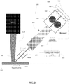
- a load cell 140 is illustrated position between one end of the feeder 106 and a surface 142. It can be appreciated that the feeder would be permitted some movement to allow a force to be registered by the load cell 140 as the feeder 106 is forced back against the surface 142.
- the force measurement is used to determine an error from a predetermined force set point. Based on the force error, a resistive heating current supplied to the wire 108 is adjusted.
- the adjustment in the resistive heating current takes into account a predetermined system gain factor.
- the gain factor represents a correction value associated with system response time.
- an end 116 of the wire 108 is preheated with a high energy heat source, such as a laser 118.
- Wire force feedback is then used instead of, or in addition to, voltage and current feedback to achieve a controlled start and prevent arcing, as described in further detail below.
- the gun 104 and laser 118 are aligned so that the wire 108 will touch the workpiece just ahead or just inside the advancing edge of where the laser 118 would hit the workpiece, Then the start of the hotwire process starts with the wire 108 feeding toward the workpiece.
- the wire feeding is stopped and a level of current is applied so that the majority of the wire 108 does not heat to a point where it loses its stiffness.
- the laser 118 (or other high intensity energy source) is turned on.
- the wire is stationary for a given period of time to let the end of the wire heat up to a plastic state.
- the wire feed speed is ramped up to the final steady state wire feed speed.
- the detected force is above a threshold or limit, either the wire feed speed ramp is slowed or the welding current is increased to return to the desired force.
- the force is set to a level which correlates to the end of the wire plastically deforming.
- the welding apparatus control circuitry 115 obtains a measurement of force feedback from the wire 108.
- the force feedback from the wire 108 may be measured directly via a force measuring device, such as a dynamometer or a load cell transducer built into or otherwise connected to the welding apparatus 102, or it may be inferred based on the variation in the wire feed current required by the motor 106 to keep the wire feed speed constant.
- the control circuitry 115 determines an error in the force feedback reading with respect to a predetermined force feedback set point or threshold range that, for instance, corresponds to the state of plastic deformation at the wire tip 116.
- step 404 if the force error is within the predetermined force error threshold range, the method returns to step 400. Otherwise, in steps 404-406, if the force error is outside of a predetermined threshold, the control circuitry 115 either increases or decreases resistive heating current applied to the wire so as to correspondingly increase or decrease the wire temperature to ensure plastic deformation at the tip 116, while preventing the tip 116 of the wire 108 from becoming liquid. For example, a force error determination that is above the predetermined threshold indicates that the temperature of the wire 108 needs to be increased to facilitate plastic deformation at the tip 116. On the other hand, a force error determination below the predetermined threshold indicates that wire temperature needs to be decreased to prevent the tip 116 from becoming liquid. Alternatively or in addition, the control circuitry 115 varies one or more of the wire feed speed and power output of the laser 118 in order to ensure plastic deformation of the wire tip 116, while preventing it from turning liquid.
- each overall loop could take place in a matter of microseconds or less, depending upon the calibration of the feedback system.
- the welding apparatus control circuitry 115 obtains a measurement of force feedback from the wire 108.
- the force feedback from the wire 108 may be measured directly via a force measuring device, such as a dynamometer or a load cell transducer built into or otherwise connected to the welding apparatus 102, or it may be inferred based on the variation in the wire feed current required by the motor 106 to keep the wire feed speed constant.
- step 422 the control circuitry 115 determines whether the force feedback has increased or is increasing relative to a past measurement. Although not illustrated, the rate of increase could be determined as well, using, e.g., a series of measurements, and the differences between. In step 424, if the force feedback is increasing, the wire heating current is increased to counter the increased resistance. Then the process returns to step 420 for another measurement.
- step 426 determines if the force feedback has decreased or is decreasing.
- the rate of decrease could be determined as well, using, e.g., a series of measurements, and the differences between.
- step 426 if the force feedback is decreasing, the wire heating current is decreased to counter the decreased resistance. Then the process returns to step 420 for another measurement.
- step 420 If the force feedback is neither increased/increasing nor decreased/decreasing, the process returns to step 420 for another measurement.
- this process correspondingly increases or decreases the wire temperature to ensure plastic deformation at the tip 116 while preventing the tip 116 of the wire 108 from becoming liquid.
- the control circuitry 115 can vary one or more of the wire feed speed and power output of the laser 118 in order to ensure plastic deformation of the wire tip 116, while preventing it from turning liquid.
- step 500 the gun 104 is aligned with a high energy heat source device, such as the laser 118.
- the control circuitry 115 directs the motor 106 to begin feeding the wire 108 toward the workpiece 110 until it has determined that the wire 108 is touching the workpiece 110.
- the control circuitry 115 determines the initial contact of the wire 108 with the workpiece 110 when a predetermined minimum wire force feedback is detected or a voltage signal is detected.
- the control circuitry 115 sets the resistive heating current applied to the wire so that most of the wire extending from the contact tip remains stiff and activates the laser 118.
- the wire 108 remains stationary until the tip 116 heats up to a plastic state.
- a plastic state is achieved when the tip 116 is easily deformed, also known as the state of plastic deformation.
- the plastic state of the tip 116 is detected when the force feedback from the wire is reduced from the force corresponding to detection of the initial contact to a predetermined lower force threshold.
- control circuitry 115 directs the motor 106 to ramp up the wire feed speed up to a steady state speed for the welding or cladding operation and controls the welding or cladding process via the force feedback method discussed above in connection with Figure 4 .
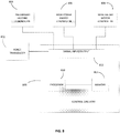
- control circuitry 800 is interconnected with at least one sensor transducer 802, a preliminary wire heater controller 804, a high power energy source controller 806 and a wire feeder motor controller 808.
- the control circuit 800 operates as described above to receive a force signal indicative of a force on the wire from the transducer 802 and to control operation of the various controllers in accordance with the principles discussed herein, namely, to start and/or adjust preliminary heating of the wire via appropriate signal to controller 804, start and/or adjust application of the high power energy to the wire via appropriate signals to the controller 806, and start, stop and/or adjust the feed speed of the wire feeder motor via appropriate signals to the controller 808.
- control circuitry 800 includes a processor 810 couple to an input/output section 812 via which signals are input from and output to the transducer and the controllers.
- Logic executed by the processor is stored in the memory 814ogic executed by the processor is stored in the memory 814 coupled to the processor 810. It can be appreciated that the logic can be in the form of software, firmware or hardware.
- FIG. 9 there is illustrated another control scheme.
- the energy delivered to the wire for heating e.g., resistive heating
- Feeder motor current is used as a control variable in a force back loop.
- T the torque applied by the feed motor
- r driveroll the radius of the drive roll of the wire feeder
- ⁇ a constant
- F wire the force on the wire
- I motor is the wire feeder motor current. In essence, this provides a constant torque feed system.
- a force set point F wire set point is compared to the force feedback signal F fbk , which is either derived from a sensor, such as a load cell or dynamometer, or from the feeder motor current I motor .
- the force feedback Ffbk is proportional to the motor current Imotor.
- the comparison is effected by a summation function F.
- the output of the summation function F becomes the force feedback error ⁇ force , which is equal to F fbk -F wire set point .
- This output ⁇ force is feed into a proportional-integral-derivative (PID) controller C with appropriate filters and gains to generate a current difference output ⁇ I.
- PID proportional-integral-derivative
- process flow diagrams are provided merely as illustrative examples and are not intended to require or imply that the steps of the various embodiments must be performed in the order presented. As will be appreciated by one of skill in the art the steps in the foregoing embodiments may be performed in any order. Words such as “then,” “next,” etc. are not intended to limit the order of the steps; these words are simply used to guide the reader through the description of the methods.
- process flow diagrams may describe the operations as a sequential process, many of the operations can be performed in parallel or concurrently. In addition, the order of the operations may be re-arranged.
- a process may correspond to a method, a function, a procedure, a subroutine, a subprogram, etc. When a process corresponds to a function, its termination may correspond to a return of the function to the calling function or the main function.
- Embodiments implemented in computer software may be implemented in software, firmware, middleware, microcode, hardware description languages, or any combination thereof.
- a code segment or machine-executable instructions may represent a procedure, a function, a subprogram, a program, a routine, a subroutine, a module, a software package, a class, or any combination of instructions, data structures, or program statements.
- a code segment may be coupled to another code segment or a hardware circuit by passing and/or receiving information, data, arguments, parameters, or memory contents.
- Information, arguments, parameters, data, etc. may be passed, forwarded, or transmitted via any suitable means including memory sharing, message passing, token passing, network transmission, etc.
- the functions When implemented in software, the functions may be stored as one or more instructions or code on a non-transitory computer-readable or processor-readable storage medium.
- the steps of a method or algorithm disclosed here may be embodied in a processor-executable software module which may reside on a computer-readable or processor-readable storage medium.
- a non-transitory computer-readable or processor-readable media includes both computer storage media and tangible storage media that facilitate transfer of a computer program from one place to another.
- a non-transitory processor-readable storage media media and tangible storage media that facilitate transfer of a computer program from one place to another.
- a non-transitory processor-readable storage media may be any available media that may be accessed by a computer.
- non-transitory processor-readable media may comprise RAM, ROM, EEPROM, CD-ROM or other optical disk storage, magnetic disk storage or other magnetic storage devices, or any other tangible storage medium that may be used to store desired program code in the form of instructions or data structures and that may be accessed by a computer or processor.
- Disk and disc include compact disc (CD), laser disc, optical disc, digital versatile disc (DVD), floppy disk, and Blu-ray disc where disks usually reproduce data magnetically, while discs reproduce data optically with lasers. Combinations of the above should also be included within the scope of computer-readable media.
- the operations of a method or algorithm may reside as one or any combination or set of codes and/or instructions on a non-transitory processor-readable medium and/or computer-readable medium, which may be incorporated into a computer program product.
Landscapes
- Engineering & Computer Science (AREA)
- Physics & Mathematics (AREA)
- Mechanical Engineering (AREA)
- Plasma & Fusion (AREA)
- Optics & Photonics (AREA)
- Lining Or Joining Of Plastics Or The Like (AREA)
- Wire Processing (AREA)
Description
- The present disclosure relates generally to metalworking equipment and methods, and more specifically to welding, cladding and additive manufacturing control systems. Such a metalworking equipment and method are known for example from
US2011/297658 A1 , which represents the closest prior-art to the subject-matter of the appended claims. It discloses, a method for controlling a start of a metalworking operation comprising; detecting a contact between a wire being fed from a wire feeding apparatus and a workpiece; with the wire in contact with the workpiece, activating a high energy heat source configured to heat a tip of the wire to a softened state; wherein, the method includes measuring a force feedback from the wire contacting the workpiece. - Hot wire welding and cladding are processes where a metal filler wire is resistively heated, typically, to a softened or plastic or semi-liquidus state, usually by passing an electrical current through it. This reduces the amount of added heat from another source needed for the base metal of a workpiece to which the heated wire is applied. The wire is typically fed in front of or behind a high-power energy source such as a laser or plasma that further melts the wire material, often along with the base metal of the workpiece, to produce a weld or clad. This puddle can also be referred to as the welding or cladding spot.
- Wire feeders are used in various welding and cladding applications to feed the wire to the welding or cladding spot. Such wire can be referred to as filler wire, additive wire or consumable wire.
- During operation, the wire is fed into or near the puddle. This way, when a workpiece is moved relative to the welding or cladding arrangement (with either the workpiece moved or the welding or cladding equipment moved), the puddle can be maintained to create a continuous weld or cladding layer.
- In hot wire welding, the start of wire feeding is sequenced very precisely to prevent arcing, or overfeeding of the wire before the process can stabilize and be in a steady state. Commonly, first the wire feed is initiated. Second, the wire contacts the workpiece. Third, heating power (e.g., electrical current applied through the wire, which has some resistance) is applied to the wire. Fourth, the wire heats to a softened/plastic/semi-liquidus phase at the weld/clad spot, namely the weld/clad puddle. Fifth, feeding and sustained high power energy heating of the wire occurs in the steady state.
- The use of hot wire welding, such as tungsten inert gas welding, tends to be more part-related and industry-related. For example, hot wire TIG is used extensively in the transportation and power generation industries. It's big in shipbuilding, and for rebuilding turbine shafts for large power plants. Hot wire TIG also is used in cladding very large valve welds such as those for oil industry in which welders clad the inside of the valve weld with high-performance alloys.
- Current hot wire welding and cladding machines rely on welding voltage and current to control the process of resistively heating a wire. These parameters may also be used to calculate power, resistance, and extension. It is important to control the resistive heating process so that the wire is heated to sufficient temperature but also so that an arc is not generated between the wire and the workpiece. The temperature of the wire should be high enough that the wire plastically deforms at its end. However, if the temperature is too high, the end of the wire will turn liquid and electromagnetic pinch forces can cause an arc to be established. Arcing will disrupt the precise resistive heating going into the wire, can cause inconsistencies throughout the weld, and will require eye protection from the arc rays. Arcing can also be detrimental to cladding processes by causing considerable base metal melting, thus influencing the dilution of the cladding. The process of starting the welding or cladding operation is particularly prone to arcing.
- The above shortcomings are overcome by a method for controlling a start of a metalworking operation as defined by appended claim 1 and by a metalworking apparatus according to appended claim 1. Preferred embodiments of the method and the apparatus are defined in their respective dependent claims. The preferred embodiments of the present invention are described with reference to the accompanying drawings.
- The present disclosure can be better understood by referring to the following figures. The components in the figures are not necessarily to scale, emphasis instead being placed upon illustrating the principles of the disclosure. In the figures, reference numerals designate corresponding parts throughout the different views.
-
FIG. 1 is a diagram illustrating an exemplary welding system of the present invention. -
FIG. 2 is a diagram illustrating another exemplary welding system of the present invention. -
FIGS. 3-4 are block diagrams illustrating a hot wire operation of the welding system ofFIG. 1 in further detail, according to an embodiment of the present invention. -
FIG. 5 is a flow chart illustrating a method of force control operation of the welding system ofFIG. 1 , according to an embodiment of the present invention. -
FIG. 6 is a flow chart illustrating another method of force control operation of welding system ofFig. 1 according to the present invention. -
FIG. 7 is a flow chart illustrating a method of force control start operation of the welding system ofFIG. 1 , according to an embodiment of the present invention. -
FIG. 8 illustrates in block diagram form a control arrangement of the present invention. -
FIG. 9 illustrates another control arrangement of the present invention. - The present disclosure is herein described in detail with reference to embodiments illustrated in the drawings, which form a part hereof. The illustrative embodiments described in the detailed description are not meant to be limiting of the subject matter presented herein.
- Reference will now be made to the exemplary embodiments of the present invention illustrated in the drawings, and specific language will be used herein to describe the same. It will nevertheless be understood that no limitation of the scope of the invention is thereby intended. Alterations and further modifications of the inventive features illustrated herein, and additional applications of the Referring to
Figure 1 , a hotwire metalworking system 100 is shown. Although referred to herein mostly as a welding or cladding system, it can be understood that the principles disclosed herein are equally applicable to an additive manufacturing process, given the similar feeding of wire and the application of cladding principles to build up layers of metal from the wire to produce a product. - As discussed in further detail below, the
system 100 uses force feedback from the wire to control the welding or cladding operation throughout the entire process. Since the force generated by the wire with plastic deformation at the tip is substantially similar among different wires and wire types, using force feedback from the wire to control the process eliminates or significantly reduces the need to change control programs governing the operation of the welding apparatus, as well as the need to enter specific wire parameters when changing wires. - In the illustrated embodiment, the
system 100 includes a welding apparatus 102 (also representative of a cladding or additive manufacturing apparatus) having a gun 104. Theapparatus 102 further includes anelectric motor 106 that feeds thewire 108 onto theworkpiece 110. Themotor 106 operatesdrive rolls 112 that feed thewire 108 through the gun 104. Thewire 108 is heated by a resistiveheating power supply 114, which applies resistive heating current to thewire 108 contacting theworkpiece 110. In various embodiments, the resistiveheating power supply 114 is an AC or DC power supply controlled by acontrol circuitry 115 associated with thewelding apparatus 102. Although the resistiveheating power supply 114 and thecontrol circuitry 115 are schematically illustrated as being external to thewelding apparatus 102, those skilled in the art will realize that thepower supply 114 and/or thecontrol circuitry 115 may be either internal or external to thewelding apparatus 102. - Those skilled in the art will understand that the control circuitry is representative of various circuit configurations that can implement a control logic such as a proportional control, a proportional-integral-differential control or any other suitable control that uses a feedback signal to adjust an operating parameter. Further, the
control circuitry 115 is representative of different circuit structures for implementing such control logic, be it analog or digital control, and whether it be implemented using hardware, firmware, software or some combination of the foregoing. Thecontrol circuitry 115 may include a processor to execute program code which is stored in a separate non-transitory memory device or integrated into the processor chip itself. - Further, those skilled in the art will also understand that although a resistive heating arrangement is described, other methods and arrangements can be used such as heat sources.
- In embodiments, the force from the
wire 108 may be determined or indicated by various devices including a force measuring device, such as a load cell transducer built into the gun 104 or by using a stand-alone apparatus that directly measures the force. A dynamometer can be attached to the feeder motor shaft and torque exerted by the feeder motor can be measured. Additionally, a suitable speed sensor can be used to measure motor shaft or feeder drive wheel speed, with speed correlated to the amount of torque exerted by the motor. - In other embodiments, the force from the
wire 108 may be inferred from another measurement, such as the wire feed motor current, that indirectly measures the force. In one embodiment, the current that is sent to the motor of the feeder106 varies to maintain a constant wire feed speed. If there is a large force at the end of thewire 108, pushing back in the direction of wire travel, the motor of the feeder106 will need an increase in the current to be able to keep feeding thewire 108 forward at the desired constant speed. Based on the variations in the wire feed current supplied to themotor 106, a force at the wire tip can be inferred. Methods and circuitry for reading motor currents are well known, as are methods and circuitry for detecting increase in motor current due to, e.g., counter forces on the rotation of the shaft of the motor. - In
Figure 2 , aload cell 140 is illustrated position between one end of thefeeder 106 and asurface 142. It can be appreciated that the feeder would be permitted some movement to allow a force to be registered by theload cell 140 as thefeeder 106 is forced back against thesurface 142. - The force measurement, whether direct or indirect, is used to determine an error from a predetermined force set point. Based on the force error, a resistive heating current supplied to the
wire 108 is adjusted. Optionally, the adjustment in the resistive heating current takes into account a predetermined system gain factor. In an embodiment, the gain factor represents a correction value associated with system response time. As further shown inFigures 3-4 , an increase in resistive heating current raises the temperature in thewire 108 and makesplastic deformation 120 atwire tip 116 easier, which results in a lower force reading. A decrease in resistive heating current lowers the temperature in thewire 108 and makesplastic deformation 120 more difficult, which results in a larger force reading. - To achieve a controlled start of the welding or cladding operation, an
end 116 of thewire 108 is preheated with a high energy heat source, such as alaser 118. Wire force feedback is then used instead of, or in addition to, voltage and current feedback to achieve a controlled start and prevent arcing, as described in further detail below. - Thus, in accordance with principles disclosed herein, the gun 104 and
laser 118 are aligned so that thewire 108 will touch the workpiece just ahead or just inside the advancing edge of where thelaser 118 would hit the workpiece, Then the start of the hotwire process starts with thewire 108 feeding toward the workpiece. When it is sensed, by a force feedback (direct or indirect), voltage feedback or both, that thewire 108 is touching the workpiece, the wire feeding is stopped and a level of current is applied so that the majority of thewire 108 does not heat to a point where it loses its stiffness. Then the laser 118 (or other high intensity energy source) is turned on. The wire is stationary for a given period of time to let the end of the wire heat up to a plastic state. After the time period to get the end of the wire in the plastic state is up, the wire feed speed is ramped up to the final steady state wire feed speed. During the ramping up of the wire feed speed, if the detected force is above a threshold or limit, either the wire feed speed ramp is slowed or the welding current is increased to return to the desired force. The force is set to a level which correlates to the end of the wire plastically deforming. - Referring to
Figure 5 , an embodiment of a method for hot wire welding and cladding using wire force feedback is shown. Instep 400, the weldingapparatus control circuitry 115 obtains a measurement of force feedback from thewire 108. As discussed above, the force feedback from thewire 108 may be measured directly via a force measuring device, such as a dynamometer or a load cell transducer built into or otherwise connected to thewelding apparatus 102, or it may be inferred based on the variation in the wire feed current required by themotor 106 to keep the wire feed speed constant. Instep 402, thecontrol circuitry 115 determines an error in the force feedback reading with respect to a predetermined force feedback set point or threshold range that, for instance, corresponds to the state of plastic deformation at thewire tip 116. Instep 404, if the force error is within the predetermined force error threshold range, the method returns to step 400. Otherwise, in steps 404-406, if the force error is outside of a predetermined threshold, thecontrol circuitry 115 either increases or decreases resistive heating current applied to the wire so as to correspondingly increase or decrease the wire temperature to ensure plastic deformation at thetip 116, while preventing thetip 116 of thewire 108 from becoming liquid. For example, a force error determination that is above the predetermined threshold indicates that the temperature of thewire 108 needs to be increased to facilitate plastic deformation at thetip 116. On the other hand, a force error determination below the predetermined threshold indicates that wire temperature needs to be decreased to prevent thetip 116 from becoming liquid. Alternatively or in addition, thecontrol circuitry 115 varies one or more of the wire feed speed and power output of thelaser 118 in order to ensure plastic deformation of thewire tip 116, while preventing it from turning liquid. - Referring to
Figure 6 , another embodiment of a method for hot wire welding and cladding using wire force feedback is shown. InFigure 6 , each overall loop could take place in a matter of microseconds or less, depending upon the calibration of the feedback system. Instep 420, the weldingapparatus control circuitry 115 obtains a measurement of force feedback from thewire 108. As discussed above, the force feedback from thewire 108 may be measured directly via a force measuring device, such as a dynamometer or a load cell transducer built into or otherwise connected to thewelding apparatus 102, or it may be inferred based on the variation in the wire feed current required by themotor 106 to keep the wire feed speed constant. Instep 422, thecontrol circuitry 115 determines whether the force feedback has increased or is increasing relative to a past measurement. Although not illustrated, the rate of increase could be determined as well, using, e.g., a series of measurements, and the differences between. Instep 424, if the force feedback is increasing, the wire heating current is increased to counter the increased resistance. Then the process returns to step 420 for another measurement. - However, if the force feedback has not increased or is not increasing, then the process proceeds to step 426 to determine if the force feedback has decreased or is decreasing. Although not illustrated, the rate of decrease could be determined as well, using, e.g., a series of measurements, and the differences between. In
step 426, if the force feedback is decreasing, the wire heating current is decreased to counter the decreased resistance. Then the process returns to step 420 for another measurement. - If the force feedback is neither increased/increasing nor decreased/decreasing, the process returns to step 420 for another measurement.
- Again, this process correspondingly increases or decreases the wire temperature to ensure plastic deformation at the
tip 116 while preventing thetip 116 of thewire 108 from becoming liquid. Alternatively or in addition, thecontrol circuitry 115 can vary one or more of the wire feed speed and power output of thelaser 118 in order to ensure plastic deformation of thewire tip 116, while preventing it from turning liquid. - Although not expressly depicted in the drawings, it may be desirable to include some hysteresis in the feedback and adjustment process avoid unnecessary or detrimental constant minor adjustments or to accommodate adjustment reaction times.
- Referring to
Figure 7 , an embodiment of a method for controlling a start of a hot wire welding or cladding operation is shown. Instep 500, the gun 104 is aligned with a high energy heat source device, such as thelaser 118. In steps 502-506, thecontrol circuitry 115 directs themotor 106 to begin feeding thewire 108 toward theworkpiece 110 until it has determined that thewire 108 is touching theworkpiece 110. In an embodiment, thecontrol circuitry 115 determines the initial contact of thewire 108 with theworkpiece 110 when a predetermined minimum wire force feedback is detected or a voltage signal is detected. At that point, in steps 508-510, thecontrol circuitry 115 sets the resistive heating current applied to the wire so that most of the wire extending from the contact tip remains stiff and activates thelaser 118. Instep 512, thewire 108 remains stationary until thetip 116 heats up to a plastic state. In an embodiment, a plastic state is achieved when thetip 116 is easily deformed, also known as the state of plastic deformation. In one embodiment, the plastic state of thetip 116 is detected when the force feedback from the wire is reduced from the force corresponding to detection of the initial contact to a predetermined lower force threshold. Finally, once thewire tip 116 heats up to the plastic state, thecontrol circuitry 115 directs themotor 106 to ramp up the wire feed speed up to a steady state speed for the welding or cladding operation and controls the welding or cladding process via the force feedback method discussed above in connection withFigure 4 . - In
Figure 8 , there is illustrated a circuit arrangement in which controlcircuitry 800 is interconnected with at least onesensor transducer 802, a preliminarywire heater controller 804, a high powerenergy source controller 806 and a wirefeeder motor controller 808. Thecontrol circuit 800 operates as described above to receive a force signal indicative of a force on the wire from thetransducer 802 and to control operation of the various controllers in accordance with the principles discussed herein, namely, to start and/or adjust preliminary heating of the wire via appropriate signal tocontroller 804, start and/or adjust application of the high power energy to the wire via appropriate signals to thecontroller 806, and start, stop and/or adjust the feed speed of the wire feeder motor via appropriate signals to thecontroller 808. - As illustrated, in an embodiment, the
control circuitry 800 includes aprocessor 810 couple to an input/output section 812 via which signals are input from and output to the transducer and the controllers. Logic executed by the processor is stored in the memory 814ogic executed by the processor is stored in thememory 814 coupled to theprocessor 810. It can be appreciated that the logic can be in the form of software, firmware or hardware. - In
Figure 9 , there is illustrated another control scheme. In this scheme, the energy delivered to the wire for heating (e.g., resistive heating) can be maintained at a constant level while the force exerted by the feeder and/or the wire on the feeder is controlled. Feeder motor current is used as a control variable in a force back loop. For this purpose, the following relationship is used:
- To that end, a force set point Fwire set point is compared to the force feedback signal Ffbk, which is either derived from a sensor, such as a load cell or dynamometer, or from the feeder motor current Imotor. The force feedback Ffbk is proportional to the motor current Imotor. In
Figure 9 , the comparison is effected by a summation function F. - The output of the summation function F becomes the force feedback error Σforce, which is equal to Ffbk-Fwire set point. This output Σforce is feed into a proportional-integral-derivative (PID) controller C with appropriate filters and gains to generate a current difference output ΔI. This output ΔI is used to control the motor by adjusting feed motor command signal Imotor, which in turn is used to control the amount of current fed to the motor. This adjustment is accomplished by increasing or decreasing the current fed to the motor, depending on the result of the summation as reflected in the signal Imotor. For this the relationship is

- While various aspects and embodiments have been disclosed, other aspects and embodiments are contemplated. The various aspects and embodiments disclosed are for purposes of illustration and are not intended to be limiting, with the true scope and spirit being indicated by the following claims.
- The foregoing method descriptions and the process flow diagrams are provided merely as illustrative examples and are not intended to require or imply that the steps of the various embodiments must be performed in the order presented. As will be appreciated by one of skill in the art the steps in the foregoing embodiments may be performed in any order. Words such as "then," "next," etc. are not intended to limit the order of the steps; these words are simply used to guide the reader through the description of the methods. Although process flow diagrams may describe the operations as a sequential process, many of the operations can be performed in parallel or concurrently. In addition, the order of the operations may be re-arranged. A process may correspond to a method, a function, a procedure, a subroutine, a subprogram, etc. When a process corresponds to a function, its termination may correspond to a return of the function to the calling function or the main function.
- The various illustrative logical blocks, modules, circuits, and algorithm steps described in connection with the embodiments disclosed here may be implemented as electronic hardware, computer software, or combinations of both. To clearly illustrate this interchangeability of hardware and software, various illustrative components, blocks, modules, circuits, and steps have been described above generally in terms of their functionality. Whether such functionality is implemented as hardware or software depends upon the particular application and design constraints imposed on the overall system. Skilled artisans may implement the described functionality in varying ways for each particular application, but such implementation decisions should not be interpreted as causing a departure from the scope of the present invention.
- Embodiments implemented in computer software may be implemented in software, firmware, middleware, microcode, hardware description languages, or any combination thereof. A code segment or machine-executable instructions may represent a procedure, a function, a subprogram, a program, a routine, a subroutine, a module, a software package, a class, or any combination of instructions, data structures, or program statements. A code segment may be coupled to another code segment or a hardware circuit by passing and/or receiving information, data, arguments, parameters, or memory contents. Information, arguments, parameters, data, etc. may be passed, forwarded, or transmitted via any suitable means including memory sharing, message passing, token passing, network transmission, etc.
- The actual software code or specialized control hardware used to implement these systems and methods is not limiting of the invention. Thus, the operation and behavior of the systems and methods were described without reference to the specific software code being understood that software and control hardware can be designed to implement the systems and methods based on the description here.
- When implemented in software, the functions may be stored as one or more instructions or code on a non-transitory computer-readable or processor-readable storage medium. The steps of a method or algorithm disclosed here may be embodied in a processor-executable software module which may reside on a computer-readable or processor-readable storage medium. A non-transitory computer-readable or processor-readable media includes both computer storage media and tangible storage media that facilitate transfer of a computer program from one place to another. A non-transitory processor-readable storage media media and tangible storage media that facilitate transfer of a computer program from one place to another. A non-transitory processor-readable storage media may be any available media that may be accessed by a computer. By way of example, and not limitation, such non-transitory processor-readable media may comprise RAM, ROM, EEPROM, CD-ROM or other optical disk storage, magnetic disk storage or other magnetic storage devices, or any other tangible storage medium that may be used to store desired program code in the form of instructions or data structures and that may be accessed by a computer or processor. Disk and disc, as used here, include compact disc (CD), laser disc, optical disc, digital versatile disc (DVD), floppy disk, and Blu-ray disc where disks usually reproduce data magnetically, while discs reproduce data optically with lasers. Combinations of the above should also be included within the scope of computer-readable media. Additionally, the operations of a method or algorithm may reside as one or any combination or set of codes and/or instructions on a non-transitory processor-readable medium and/or computer-readable medium, which may be incorporated into a computer program product.
- The preceding description of the disclosed embodiments is provided to enable any person skilled in the art to make and use the present invention. Various modifications to these embodiments will be readily apparent to those skilled in the art, and the generic principles defined here may be applied to other embodiments as far as they fall within the scope of the invention as defined by the attached claims. Thus, the present invention is not intended to be limited to the embodiments shown here but is to be accorded the widest scope consistent with the following claims and the principles and novel features disclosed here.
Claims (15)
- A method for controlling a start of a metalworking operation performed with a welding apparatus (102), comprising:detecting an initial contact between a wire (108) being fed from a wire feeding apparatus (106, 112) and a workpiece (110); in response to the detection, halting feeding of the wire (108) from the welding apparatus (102);with the wire (108) in contact with the workpiece (110), activating a high energy heat source (118) configured to heat a tip of the wire (116) to a softened state; andafter application of the high energy heat source (118) is activated, resuming the feeding of the wire (108) from the wire feeding apparatus (106), wherein,the feeding of the wire (108) is resumed by measuring a force feedback from the wire contacting the workpiece.
- The method of claim 1, wherein after initial contact of the wire (108) with the workpiece (110) and prior to activating the high energy heat source (118) configured to heat a tip of the wire (116) to a plastic state, the wire (108) is subjected to preliminary heating with another energy source, or
wherein the wire is subjected to resistive heating with another energy source. - The method of claim 1 or 2 wherein the initial contact is detected based on the force feedback, and
wherein the plastic state is detected when the force feedback from the wire (108) is reduced below a force corresponding to the detection of the initial contact. - The method of one of the preceding claims, wherein the high energy heat source (118) is a laser or a plasma.
- The method of one of the preceding claims, further comprising:determining, by circuitry including control circuitry (115), a force error for the force feedback based on a predetermined force threshold; andadjusting, by the circuitry (115), heating of the wire (108), a feed rate of the wire (108), orboth based at least in part on the force error when the force error is outside of the predetermined force threshold;increasing, by circuitry including a control circuitry (115), the heating current when the force error is above the predetermined force threshold; and decreasing, by the circuitry (115), the heating current when the force error is below the predetermined force threshold;wherein the control circuitry (115) implements a constant torque control scheme.
- The method of one of the preceding claims, further comprising maintaining, by the circuitry (115), a constant wire feed speed after resuming the feeding of the wire (108).
- The method of one of the preceding claims, wherein the force feedback is measured directly via a force measurement device , or
wherein the force feedback is measured using a load cell (140) or a dynamometer. - The method of one of the preceding claims, wherein the force feedback is inferred based on a change in a feed motor current of the wire feeding apparatus (106, 112),
wherein the control circuitry (115) varies the feed motor current to maintain a constant wire feed speed. - A metalworking apparatus comprising:a wire feed mechanism (106, 112) configured to feed a wire (108) from a gun (104) onto a workpiece (110); a heating power supply (114) configured to supply a heating current to the wire;a high energy heat source (118) configured to heat a tip of the wire (116); a force measuring device; andcircuitry (115) configured to (a) detect an initial contact between the wire being fed from the welding gun (104) and the workpiece (110), (b) in response to the detection, halt feeding of the wire (108) from the welding gun (104), (c) activate the high energy heat source to heat the tip of the wire (116), and (d) resume the feeding of the wire (108) from the welding 2. gun (104) when the tip of the wire (116) is heated by the high energy heat source (118) to a softened state, wherein,the feeding of the wire (108) is resumed by measuring a force feedback from the wire contacting the workpiece.
- The apparatus of claim 9 wherein the initial contact is detected based on the force feedback,
wherein the plastic state is detected when the force feedback from the wire is reduced below a force corresponding to the detection of the initial contact. - The apparatus of claim 9 or 10 wherein the high energy heat source (118) is a laser or a plasma.
- The apparatus of one of claims 9 to 11 wherein the circuitry (115) is further configured to:determine a force error for the force feedback based on a predetermined force threshold; andadjust the heating of the wire (108) based at least in part on the force error when the force error is outside of the predetermined force threshold;increase the heating current when the force error is above the predetermined force threshold; anddecrease the heating current when the force error is below the predetermined force threshold.
- The apparatus of one of claims 9 to 12, wherein the circuitry (115) is further configured to maintain a constant wire feed speed or constant ramp rate after resuming the feeding of the wire (108), wherein the circuitry (115) implements a constant torque control scheme.
- The apparatus of one of claims 9 to 13 further comprising a force measurement device that directly measures the force feedback,
wherein the force measurement device is a load cell (140) or a dynamomoter. - The apparatus of one of claims 9 to 14 wherein the force feedback is inferred based on a change in a feed motor current of the wire feed mechanism (106, 112),
wherein the circuitry (115)is further configured to vary the feed motor current to maintain a constant wire feed speed.
Applications Claiming Priority (1)
| Application Number | Priority Date | Filing Date | Title |
|---|---|---|---|
| US14/943,285 US10173288B2 (en) | 2015-11-17 | 2015-11-17 | Metalworking system with force controlled wire feed start operation |
Publications (3)
| Publication Number | Publication Date |
|---|---|
| EP3170613A2 EP3170613A2 (en) | 2017-05-24 |
| EP3170613A3 EP3170613A3 (en) | 2017-05-31 |
| EP3170613B1 true EP3170613B1 (en) | 2018-04-25 |
Family
ID=56939969
Family Applications (1)
| Application Number | Title | Priority Date | Filing Date |
|---|---|---|---|
| EP16189304.5A Not-in-force EP3170613B1 (en) | 2015-11-17 | 2016-09-16 | Metalworking system with force controlled wire feed start operation |
Country Status (5)
| Country | Link |
|---|---|
| US (2) | US10173288B2 (en) |
| EP (1) | EP3170613B1 (en) |
| CN (1) | CN106944720B (en) |
| CA (1) | CA2941992C (en) |
| MX (1) | MX377218B (en) |
Cited By (1)
| Publication number | Priority date | Publication date | Assignee | Title |
|---|---|---|---|---|
| WO2024175289A1 (en) * | 2023-02-23 | 2024-08-29 | Fundación Tekniker | Laser head for wire deposition |
Families Citing this family (23)
| Publication number | Priority date | Publication date | Assignee | Title |
|---|---|---|---|---|
| GB2549653B (en) | 2014-12-12 | 2019-01-09 | Digital Alloys Incorporated | Additive manufacturing of metallic structures |
| CN107414251B (en) * | 2017-09-15 | 2019-06-04 | 唐山松下产业机器有限公司 | Welding equipment, arcing determination processing method and device |
| CN107876984B (en) * | 2017-10-31 | 2020-04-14 | 中车青岛四方机车车辆股份有限公司 | Gap welding method and device |
| CA3101061A1 (en) | 2018-06-20 | 2019-12-26 | Digital Alloys Incorporated | Multi-diameter wire feeder |
| US10969797B2 (en) * | 2018-08-29 | 2021-04-06 | Illinois Tool Works, Inc. | Mass flow valve controller and control method with set point filter and linearization system based on valve model |
| CN112867579B (en) * | 2018-10-19 | 2023-04-04 | 三菱电机株式会社 | Additive manufacturing apparatus and additive manufacturing method |
| US11229956B2 (en) * | 2018-10-22 | 2022-01-25 | Mitsubishi Electric Corporation | Numerical control device, additive manufacturing apparatus, and method for controlling additive manufacturing apparatus |
| CN109434286A (en) * | 2018-12-21 | 2019-03-08 | 陕西天元智能再制造股份有限公司 | A kind of efficient silk material laser cladding method |
| CN110253123B (en) * | 2019-06-20 | 2021-01-26 | 中船澄西新荣船舶有限公司 | Plasma welding process of duplex stainless steel 2507 with bypass wire feeding |
| CN110253124B (en) * | 2019-06-20 | 2021-01-26 | 中船澄西新荣船舶有限公司 | Plasma welding process of austenitic stainless steel 254SMo with bypass wire feeding |
| US11853033B1 (en) | 2019-07-26 | 2023-12-26 | Relativity Space, Inc. | Systems and methods for using wire printing process data to predict material properties and part quality |
| CN110773870A (en) * | 2019-09-24 | 2020-02-11 | 山东雷石智能制造股份有限公司 | A kind of multi-laser coaxial wire feeding additive manufacturing equipment and wire feeding method |
| US11465236B2 (en) * | 2019-09-26 | 2022-10-11 | GM Global Technology Operations LLC | Intelligent non-autogenous metalworking systems and control logic with automated wire-to-beam alignment |
| US12138713B2 (en) * | 2020-02-07 | 2024-11-12 | Ii-Vi Delaware, Inc. | Applied force determination and control in joining process |
| US11826861B1 (en) * | 2020-08-12 | 2023-11-28 | Sion Power Corporation | Joining systems, clamping fixtures, and related systems and methods |
| US11759875B2 (en) * | 2020-09-23 | 2023-09-19 | International Business Machines Corporation | Autonomous robotic thread for repairing structures |
| EP3984681A1 (en) * | 2020-10-19 | 2022-04-20 | FRONIUS INTERNATIONAL GmbH | Method for preparing an automated welding process on a welding process and welding device for carrying out an automated welding process |
| EP4079436A1 (en) | 2021-04-19 | 2022-10-26 | FRONIUS INTERNATIONAL GmbH | Method for controlling or regulating the feed rate of a wire made from meltable material in a laser welding or laser soldering process and laser welding or laser soldering apparatus for carrying out such a method |
| CN113681118B (en) * | 2021-09-06 | 2023-10-31 | 上海沪工焊接集团股份有限公司 | Welding parameter determination method and device, electronic equipment and medium |
| CN118871239A (en) * | 2022-06-27 | 2024-10-29 | 发那科株式会社 | Robot control device and robot system |
| EP4349600A1 (en) * | 2022-10-07 | 2024-04-10 | Helmholtz-Zentrum hereon GmbH | Method for operating a wire-based material application device and wire-based material application device |
| SE2330149A1 (en) * | 2023-04-03 | 2024-10-04 | Procada Ab | Laser metal deposition device and method |
| CN117245218B (en) * | 2023-11-14 | 2024-02-02 | 苏州融速智造科技有限公司 | Automatic gun cleaning, wire cutting and dry extension correction method and equipment system thereof |
Citations (1)
| Publication number | Priority date | Publication date | Assignee | Title |
|---|---|---|---|---|
| EP3170605A1 (en) * | 2015-11-17 | 2017-05-24 | Illinois Tool Works Inc. | Metalworking wire feeder system with force control operation |
Family Cites Families (14)
| Publication number | Priority date | Publication date | Assignee | Title |
|---|---|---|---|---|
| US4107508A (en) * | 1976-06-09 | 1978-08-15 | L'air Liquide, Societe Anonyme Pour L'etude Et L'exploitation Des Procedes Georges Claude | Method and apparatus for welding using fillet-wire |
| US6521861B2 (en) * | 2000-02-07 | 2003-02-18 | General Electric Company | Method and apparatus for increasing welding rate for high aspect ratio welds |
| CN1186161C (en) * | 2002-06-27 | 2005-01-26 | 上海交通大学 | Arc stricking method for metal gas arc welding |
| DE102006056252B4 (en) * | 2006-09-26 | 2009-06-10 | Scansonic Mi Gmbh | Device for guiding an energy beam |
| WO2008050513A1 (en) * | 2006-10-27 | 2008-05-02 | Panasonic Corporation | Automatic welding device |
| US8653417B2 (en) * | 2009-01-13 | 2014-02-18 | Lincoln Global, Inc. | Method and system to start and use a combination filler wire feed and high intensity energy source |
| US10086461B2 (en) * | 2009-01-13 | 2018-10-02 | Lincoln Global, Inc. | Method and system to start and use combination filler wire feed and high intensity energy source for welding |
| US20130327749A1 (en) * | 2009-01-13 | 2013-12-12 | Lincoln Global Inc. | Method and system to start and use combination filler wire feed and high intensity energy source for welding aluminum to steel |
| DE102009045400B3 (en) * | 2009-10-06 | 2011-06-09 | Bayerische Motoren Werke Aktiengesellschaft | Joining device for a cohesive joining by means of a filler material |
| DE102012107896A1 (en) * | 2012-08-28 | 2014-03-06 | Reinhausen Plasma Gmbh | Method and device for connecting conductors to substrates |
| US10471547B2 (en) * | 2012-12-21 | 2019-11-12 | European Space Agency | Additive manufacturing method using focused light heating source |
| US10046419B2 (en) * | 2014-01-24 | 2018-08-14 | Lincoln Global, Inc. | Method and system for additive manufacturing using high energy source and hot-wire |
| US9833862B2 (en) | 2014-01-24 | 2017-12-05 | Lincoln Global, Inc. | Method and system for additive manufacturing using high energy source and hot-wire |
| US9718147B2 (en) | 2014-03-07 | 2017-08-01 | Lincoln Global, Inc. | Method and system to start and use combination filler wire feed and high intensity energy source for root pass welding of the inner diameter of clad pipe |
-
2015
- 2015-11-17 US US14/943,285 patent/US10173288B2/en active Active
-
2016
- 2016-09-14 CA CA2941992A patent/CA2941992C/en active Active
- 2016-09-16 EP EP16189304.5A patent/EP3170613B1/en not_active Not-in-force
- 2016-11-10 CN CN201610991583.8A patent/CN106944720B/en active Active
- 2016-11-16 MX MX2016015078A patent/MX377218B/en active IP Right Grant
-
2018
- 2018-11-08 US US16/184,814 patent/US11103962B2/en active Active
Patent Citations (1)
| Publication number | Priority date | Publication date | Assignee | Title |
|---|---|---|---|---|
| EP3170605A1 (en) * | 2015-11-17 | 2017-05-24 | Illinois Tool Works Inc. | Metalworking wire feeder system with force control operation |
Cited By (1)
| Publication number | Priority date | Publication date | Assignee | Title |
|---|---|---|---|---|
| WO2024175289A1 (en) * | 2023-02-23 | 2024-08-29 | Fundación Tekniker | Laser head for wire deposition |
Also Published As
| Publication number | Publication date |
|---|---|
| EP3170613A3 (en) | 2017-05-31 |
| CN106944720A (en) | 2017-07-14 |
| MX377218B (en) | 2025-03-07 |
| EP3170613A2 (en) | 2017-05-24 |
| US11103962B2 (en) | 2021-08-31 |
| MX2016015078A (en) | 2017-05-16 |
| US20170136587A1 (en) | 2017-05-18 |
| CN106944720B (en) | 2021-11-02 |
| US20190076967A1 (en) | 2019-03-14 |
| US10173288B2 (en) | 2019-01-08 |
| CA2941992C (en) | 2023-10-17 |
| CA2941992A1 (en) | 2017-05-17 |
Similar Documents
| Publication | Publication Date | Title |
|---|---|---|
| US11103962B2 (en) | Metalworking system with force controlled wire feed start operation | |
| US10058956B2 (en) | Metalworking wire feeder system with force control operation | |
| US10828728B2 (en) | Hotwire deposition material processing system and method | |
| US12090583B2 (en) | Systems and methods for adaptive control of wire preheating | |
| EP2718052B1 (en) | System for and method of generating a weld during a start of a welding process by restricting output power | |
| US8556156B1 (en) | Dynamic adjustment of friction stir welding process parameters based on weld temperature | |
| CN107020438B (en) | Welding wire feed limiter | |
| CA2740615A1 (en) | Method and system to start and use a combination filler wire feed and high intensity energy source | |
| CN108890081B (en) | Method and apparatus for stabilizing arc length | |
| JP6472387B2 (en) | Arc welding control method | |
| CN102189314B (en) | Arc welding control method of non-consumable electrode | |
| US20230226634A1 (en) | System and method to control two wire feed motors | |
| CN108202177B (en) | Arc starting control method and device for gas shielded welding | |
| US8933362B2 (en) | Method and system for welding parts together | |
| CN112423926A (en) | Arc welding method including consumable wire |
Legal Events
| Date | Code | Title | Description |
|---|---|---|---|
| PUAI | Public reference made under article 153(3) epc to a published international application that has entered the european phase |
Free format text: ORIGINAL CODE: 0009012 |
|
| PUAL | Search report despatched |
Free format text: ORIGINAL CODE: 0009013 |
|
| 17P | Request for examination filed |
Effective date: 20160916 |
|
| AK | Designated contracting states |
Kind code of ref document: A2 Designated state(s): AL AT BE BG CH CY CZ DE DK EE ES FI FR GB GR HR HU IE IS IT LI LT LU LV MC MK MT NL NO PL PT RO RS SE SI SK SM TR |
|
| AX | Request for extension of the european patent |
Extension state: BA ME |
|
| AK | Designated contracting states |
Kind code of ref document: A3 Designated state(s): AL AT BE BG CH CY CZ DE DK EE ES FI FR GB GR HR HU IE IS IT LI LT LU LV MC MK MT NL NO PL PT RO RS SE SI SK SM TR |
|
| AX | Request for extension of the european patent |
Extension state: BA ME |
|
| RIC1 | Information provided on ipc code assigned before grant |
Ipc: B23K 10/02 20060101ALI20170427BHEP Ipc: B23K 26/21 20140101ALI20170427BHEP Ipc: B23K 26/342 20140101AFI20170427BHEP Ipc: B23K 26/70 20140101ALI20170427BHEP |
|
| REG | Reference to a national code |
Ref country code: DE Ref legal event code: R079 Ref document number: 602016002653 Country of ref document: DE Free format text: PREVIOUS MAIN CLASS: B23K0026342000 Ipc: B23K0037000000 |
|
| RIC1 | Information provided on ipc code assigned before grant |
Ipc: B23K 26/70 20140101ALI20171109BHEP Ipc: B23K 10/02 20060101ALI20171109BHEP Ipc: B23K 101/34 20060101ALI20171109BHEP Ipc: B23K 37/00 20060101AFI20171109BHEP Ipc: B23K 26/21 20140101ALI20171109BHEP Ipc: H05B 3/00 20060101ALI20171109BHEP Ipc: B23K 26/342 20140101ALI20171109BHEP Ipc: B23K 31/00 20060101ALI20171109BHEP |
|
| GRAP | Despatch of communication of intention to grant a patent |
Free format text: ORIGINAL CODE: EPIDOSNIGR1 |
|
| INTG | Intention to grant announced |
Effective date: 20171218 |
|
| GRAS | Grant fee paid |
Free format text: ORIGINAL CODE: EPIDOSNIGR3 |
|
| GRAA | (expected) grant |
Free format text: ORIGINAL CODE: 0009210 |
|
| AK | Designated contracting states |
Kind code of ref document: B1 Designated state(s): AL AT BE BG CH CY CZ DE DK EE ES FI FR GB GR HR HU IE IS IT LI LT LU LV MC MK MT NL NO PL PT RO RS SE SI SK SM TR |
|
| REG | Reference to a national code |
Ref country code: GB Ref legal event code: FG4D |
|
| REG | Reference to a national code |
Ref country code: CH Ref legal event code: EP |
|
| REG | Reference to a national code |
Ref country code: AT Ref legal event code: REF Ref document number: 992369 Country of ref document: AT Kind code of ref document: T Effective date: 20180515 |
|
| REG | Reference to a national code |
Ref country code: IE Ref legal event code: FG4D |
|
| REG | Reference to a national code |
Ref country code: DE Ref legal event code: R096 Ref document number: 602016002653 Country of ref document: DE |
|
| REG | Reference to a national code |
Ref country code: NL Ref legal event code: MP Effective date: 20180425 |
|
| REG | Reference to a national code |
Ref country code: LT Ref legal event code: MG4D |
|
| PG25 | Lapsed in a contracting state [announced via postgrant information from national office to epo] |
Ref country code: NL Free format text: LAPSE BECAUSE OF FAILURE TO SUBMIT A TRANSLATION OF THE DESCRIPTION OR TO PAY THE FEE WITHIN THE PRESCRIBED TIME-LIMIT Effective date: 20180425 |
|
| PG25 | Lapsed in a contracting state [announced via postgrant information from national office to epo] |
Ref country code: BG Free format text: LAPSE BECAUSE OF FAILURE TO SUBMIT A TRANSLATION OF THE DESCRIPTION OR TO PAY THE FEE WITHIN THE PRESCRIBED TIME-LIMIT Effective date: 20180725 Ref country code: NO Free format text: LAPSE BECAUSE OF FAILURE TO SUBMIT A TRANSLATION OF THE DESCRIPTION OR TO PAY THE FEE WITHIN THE PRESCRIBED TIME-LIMIT Effective date: 20180725 Ref country code: FI Free format text: LAPSE BECAUSE OF FAILURE TO SUBMIT A TRANSLATION OF THE DESCRIPTION OR TO PAY THE FEE WITHIN THE PRESCRIBED TIME-LIMIT Effective date: 20180425 Ref country code: SE Free format text: LAPSE BECAUSE OF FAILURE TO SUBMIT A TRANSLATION OF THE DESCRIPTION OR TO PAY THE FEE WITHIN THE PRESCRIBED TIME-LIMIT Effective date: 20180425 Ref country code: PL Free format text: LAPSE BECAUSE OF FAILURE TO SUBMIT A TRANSLATION OF THE DESCRIPTION OR TO PAY THE FEE WITHIN THE PRESCRIBED TIME-LIMIT Effective date: 20180425 Ref country code: ES Free format text: LAPSE BECAUSE OF FAILURE TO SUBMIT A TRANSLATION OF THE DESCRIPTION OR TO PAY THE FEE WITHIN THE PRESCRIBED TIME-LIMIT Effective date: 20180425 Ref country code: LT Free format text: LAPSE BECAUSE OF FAILURE TO SUBMIT A TRANSLATION OF THE DESCRIPTION OR TO PAY THE FEE WITHIN THE PRESCRIBED TIME-LIMIT Effective date: 20180425 |
|
| PG25 | Lapsed in a contracting state [announced via postgrant information from national office to epo] |
Ref country code: RS Free format text: LAPSE BECAUSE OF FAILURE TO SUBMIT A TRANSLATION OF THE DESCRIPTION OR TO PAY THE FEE WITHIN THE PRESCRIBED TIME-LIMIT Effective date: 20180425 Ref country code: LV Free format text: LAPSE BECAUSE OF FAILURE TO SUBMIT A TRANSLATION OF THE DESCRIPTION OR TO PAY THE FEE WITHIN THE PRESCRIBED TIME-LIMIT Effective date: 20180425 Ref country code: HR Free format text: LAPSE BECAUSE OF FAILURE TO SUBMIT A TRANSLATION OF THE DESCRIPTION OR TO PAY THE FEE WITHIN THE PRESCRIBED TIME-LIMIT Effective date: 20180425 Ref country code: GR Free format text: LAPSE BECAUSE OF FAILURE TO SUBMIT A TRANSLATION OF THE DESCRIPTION OR TO PAY THE FEE WITHIN THE PRESCRIBED TIME-LIMIT Effective date: 20180726 |
|
| REG | Reference to a national code |
Ref country code: AT Ref legal event code: MK05 Ref document number: 992369 Country of ref document: AT Kind code of ref document: T Effective date: 20180425 |
|
| PG25 | Lapsed in a contracting state [announced via postgrant information from national office to epo] |
Ref country code: PT Free format text: LAPSE BECAUSE OF FAILURE TO SUBMIT A TRANSLATION OF THE DESCRIPTION OR TO PAY THE FEE WITHIN THE PRESCRIBED TIME-LIMIT Effective date: 20180827 |
|
| REG | Reference to a national code |
Ref country code: DE Ref legal event code: R097 Ref document number: 602016002653 Country of ref document: DE |
|
| PG25 | Lapsed in a contracting state [announced via postgrant information from national office to epo] |
Ref country code: DK Free format text: LAPSE BECAUSE OF FAILURE TO SUBMIT A TRANSLATION OF THE DESCRIPTION OR TO PAY THE FEE WITHIN THE PRESCRIBED TIME-LIMIT Effective date: 20180425 Ref country code: AT Free format text: LAPSE BECAUSE OF FAILURE TO SUBMIT A TRANSLATION OF THE DESCRIPTION OR TO PAY THE FEE WITHIN THE PRESCRIBED TIME-LIMIT Effective date: 20180425 Ref country code: CZ Free format text: LAPSE BECAUSE OF FAILURE TO SUBMIT A TRANSLATION OF THE DESCRIPTION OR TO PAY THE FEE WITHIN THE PRESCRIBED TIME-LIMIT Effective date: 20180425 Ref country code: RO Free format text: LAPSE BECAUSE OF FAILURE TO SUBMIT A TRANSLATION OF THE DESCRIPTION OR TO PAY THE FEE WITHIN THE PRESCRIBED TIME-LIMIT Effective date: 20180425 Ref country code: EE Free format text: LAPSE BECAUSE OF FAILURE TO SUBMIT A TRANSLATION OF THE DESCRIPTION OR TO PAY THE FEE WITHIN THE PRESCRIBED TIME-LIMIT Effective date: 20180425 Ref country code: SK Free format text: LAPSE BECAUSE OF FAILURE TO SUBMIT A TRANSLATION OF THE DESCRIPTION OR TO PAY THE FEE WITHIN THE PRESCRIBED TIME-LIMIT Effective date: 20180425 |
|
| PG25 | Lapsed in a contracting state [announced via postgrant information from national office to epo] |
Ref country code: SM Free format text: LAPSE BECAUSE OF FAILURE TO SUBMIT A TRANSLATION OF THE DESCRIPTION OR TO PAY THE FEE WITHIN THE PRESCRIBED TIME-LIMIT Effective date: 20180425 Ref country code: IT Free format text: LAPSE BECAUSE OF FAILURE TO SUBMIT A TRANSLATION OF THE DESCRIPTION OR TO PAY THE FEE WITHIN THE PRESCRIBED TIME-LIMIT Effective date: 20180425 |
|
| PLBE | No opposition filed within time limit |
Free format text: ORIGINAL CODE: 0009261 |
|
| STAA | Information on the status of an ep patent application or granted ep patent |
Free format text: STATUS: NO OPPOSITION FILED WITHIN TIME LIMIT |
|
| REG | Reference to a national code |
Ref country code: DE Ref legal event code: R119 Ref document number: 602016002653 Country of ref document: DE |
|
| 26N | No opposition filed |
Effective date: 20190128 |
|
| PG25 | Lapsed in a contracting state [announced via postgrant information from national office to epo] |
Ref country code: MC Free format text: LAPSE BECAUSE OF FAILURE TO SUBMIT A TRANSLATION OF THE DESCRIPTION OR TO PAY THE FEE WITHIN THE PRESCRIBED TIME-LIMIT Effective date: 20180425 |
|
| PG25 | Lapsed in a contracting state [announced via postgrant information from national office to epo] |
Ref country code: SI Free format text: LAPSE BECAUSE OF FAILURE TO SUBMIT A TRANSLATION OF THE DESCRIPTION OR TO PAY THE FEE WITHIN THE PRESCRIBED TIME-LIMIT Effective date: 20180425 |
|
| REG | Reference to a national code |
Ref country code: BE Ref legal event code: MM Effective date: 20180930 |
|
| REG | Reference to a national code |
Ref country code: IE Ref legal event code: MM4A |
|
| PG25 | Lapsed in a contracting state [announced via postgrant information from national office to epo] |
Ref country code: LU Free format text: LAPSE BECAUSE OF NON-PAYMENT OF DUE FEES Effective date: 20180916 |
|
| PG25 | Lapsed in a contracting state [announced via postgrant information from national office to epo] |
Ref country code: DE Free format text: LAPSE BECAUSE OF NON-PAYMENT OF DUE FEES Effective date: 20190402 Ref country code: IE Free format text: LAPSE BECAUSE OF NON-PAYMENT OF DUE FEES Effective date: 20180916 |
|
| PG25 | Lapsed in a contracting state [announced via postgrant information from national office to epo] |
Ref country code: FR Free format text: LAPSE BECAUSE OF NON-PAYMENT OF DUE FEES Effective date: 20180930 Ref country code: BE Free format text: LAPSE BECAUSE OF NON-PAYMENT OF DUE FEES Effective date: 20180930 |
|
| PG25 | Lapsed in a contracting state [announced via postgrant information from national office to epo] |
Ref country code: AL Free format text: LAPSE BECAUSE OF FAILURE TO SUBMIT A TRANSLATION OF THE DESCRIPTION OR TO PAY THE FEE WITHIN THE PRESCRIBED TIME-LIMIT Effective date: 20180425 |
|
| PG25 | Lapsed in a contracting state [announced via postgrant information from national office to epo] |
Ref country code: MT Free format text: LAPSE BECAUSE OF NON-PAYMENT OF DUE FEES Effective date: 20180916 |
|
| PG25 | Lapsed in a contracting state [announced via postgrant information from national office to epo] |
Ref country code: TR Free format text: LAPSE BECAUSE OF FAILURE TO SUBMIT A TRANSLATION OF THE DESCRIPTION OR TO PAY THE FEE WITHIN THE PRESCRIBED TIME-LIMIT Effective date: 20180425 |
|
| REG | Reference to a national code |
Ref country code: CH Ref legal event code: PL |
|
| PG25 | Lapsed in a contracting state [announced via postgrant information from national office to epo] |
Ref country code: MK Free format text: LAPSE BECAUSE OF NON-PAYMENT OF DUE FEES Effective date: 20180425 Ref country code: HU Free format text: LAPSE BECAUSE OF FAILURE TO SUBMIT A TRANSLATION OF THE DESCRIPTION OR TO PAY THE FEE WITHIN THE PRESCRIBED TIME-LIMIT; INVALID AB INITIO Effective date: 20160916 Ref country code: CY Free format text: LAPSE BECAUSE OF FAILURE TO SUBMIT A TRANSLATION OF THE DESCRIPTION OR TO PAY THE FEE WITHIN THE PRESCRIBED TIME-LIMIT Effective date: 20180425 |
|
| PG25 | Lapsed in a contracting state [announced via postgrant information from national office to epo] |
Ref country code: LI Free format text: LAPSE BECAUSE OF NON-PAYMENT OF DUE FEES Effective date: 20190930 Ref country code: CH Free format text: LAPSE BECAUSE OF NON-PAYMENT OF DUE FEES Effective date: 20190930 Ref country code: IS Free format text: LAPSE BECAUSE OF FAILURE TO SUBMIT A TRANSLATION OF THE DESCRIPTION OR TO PAY THE FEE WITHIN THE PRESCRIBED TIME-LIMIT Effective date: 20180825 |
|
| GBPC | Gb: european patent ceased through non-payment of renewal fee |
Effective date: 20200916 |
|
| PG25 | Lapsed in a contracting state [announced via postgrant information from national office to epo] |
Ref country code: GB Free format text: LAPSE BECAUSE OF NON-PAYMENT OF DUE FEES Effective date: 20200916 |