EP3170332B1 - Verfahren zur adaptiven strahlplatzierung in drahtlosen systemen - Google Patents
Verfahren zur adaptiven strahlplatzierung in drahtlosen systemen Download PDFInfo
- Publication number
- EP3170332B1 EP3170332B1 EP15742502.6A EP15742502A EP3170332B1 EP 3170332 B1 EP3170332 B1 EP 3170332B1 EP 15742502 A EP15742502 A EP 15742502A EP 3170332 B1 EP3170332 B1 EP 3170332B1
- Authority
- EP
- European Patent Office
- Prior art keywords
- communication
- beams
- sector
- directions
- time
- Prior art date
- Legal status (The legal status is an assumption and is not a legal conclusion. Google has not performed a legal analysis and makes no representation as to the accuracy of the status listed.)
- Active
Links
Images


Classifications
-
- H—ELECTRICITY
- H04—ELECTRIC COMMUNICATION TECHNIQUE
- H04B—TRANSMISSION
- H04B7/00—Radio transmission systems, i.e. using radiation field
- H04B7/02—Diversity systems; Multi-antenna system, i.e. transmission or reception using multiple antennas
- H04B7/04—Diversity systems; Multi-antenna system, i.e. transmission or reception using multiple antennas using two or more spaced independent antennas
- H04B7/06—Diversity systems; Multi-antenna system, i.e. transmission or reception using multiple antennas using two or more spaced independent antennas at the transmitting station
- H04B7/0613—Diversity systems; Multi-antenna system, i.e. transmission or reception using multiple antennas using two or more spaced independent antennas at the transmitting station using simultaneous transmission
- H04B7/0615—Diversity systems; Multi-antenna system, i.e. transmission or reception using multiple antennas using two or more spaced independent antennas at the transmitting station using simultaneous transmission of weighted versions of same signal
- H04B7/0617—Diversity systems; Multi-antenna system, i.e. transmission or reception using multiple antennas using two or more spaced independent antennas at the transmitting station using simultaneous transmission of weighted versions of same signal for beam forming
-
- H—ELECTRICITY
- H04—ELECTRIC COMMUNICATION TECHNIQUE
- H04W—WIRELESS COMMUNICATION NETWORKS
- H04W16/00—Network planning, e.g. coverage or traffic planning tools; Network deployment, e.g. resource partitioning or cells structures
- H04W16/24—Cell structures
- H04W16/28—Cell structures using beam steering
-
- H—ELECTRICITY
- H04—ELECTRIC COMMUNICATION TECHNIQUE
- H04W—WIRELESS COMMUNICATION NETWORKS
- H04W24/00—Supervisory, monitoring or testing arrangements
- H04W24/02—Arrangements for optimising operational condition
-
- H—ELECTRICITY
- H04—ELECTRIC COMMUNICATION TECHNIQUE
- H04W—WIRELESS COMMUNICATION NETWORKS
- H04W72/00—Local resource management
- H04W72/04—Wireless resource allocation
- H04W72/044—Wireless resource allocation based on the type of the allocated resource
- H04W72/046—Wireless resource allocation based on the type of the allocated resource the resource being in the space domain, e.g. beams
-
- H—ELECTRICITY
- H04—ELECTRIC COMMUNICATION TECHNIQUE
- H04W—WIRELESS COMMUNICATION NETWORKS
- H04W8/00—Network data management
- H04W8/005—Discovery of network devices, e.g. terminals
Definitions
- Embodiments of the present invention generally relate to wireless systems using narrow beams in lieu of or in addition to conventional antenna radiation patterns and methods to use these narrow beams to increase the capacity of wireless systems.
- omnidirectional antennas i.e., antennas radiating 360 degrees in at least one plane.
- Other systems such as point-to-point microwave links use directional antennas, i.e. antennas radiating mostly within a cone or beam.
- the commercial cellular systems were first introduced with omnidirectional tower antennas. Later, the wireless operators migrated to a sectorized architecture using 3 directional antennas on the tower, each covering 120 degrees in azimuth and about 15-20 degrees in elevation.
- the modem cellular network uses three sectors per cell as a virtual standard. This solution has served well the wireless operators in the past when voice communications dominated the wireless traffic. However, with the advent of smart phones and other smart mobile devices running applications with large wireless data consumption such as video on demand, the requirements on the wireless network capacity have well surpassed the capability of the cellular system. In principle, cell splitting by adding towers, base stations and antennas is a natural solution for increasing the network capacity but the high cost of this approach and the general public opposition to new cell towers present severe practical limitations.
- MIMO Multiple-Input-Multiple-Output
- U.S. patent application 13/442,561 A new method for increasing the cellular network capacity by a large amount without adding cell towers or spectrum is described in U.S. patent application 13/442,561 .
- This method is based on the use of narrow, agile, scanning beams boosting the SNIR at all places in the sector and creating the possibility for spectrum reuse, similar to MIMO but without signal processing.
- the generation of narrow beams at the tower is possible by the low cost phased array technique described in US patent #8,61 1,959 .
- the method in U.S patent application 13/442,561 requires a precise coordination between the beam placement and scanning and the scheduling of the communication times between the base station and the mobiles. A significant modification in the base station software is necessary to implement this coordination.
- US 2013/095846 A1 discloses a system for facilitating improved macro network coverage for an area with a high user density is known. Further, from US 2011/085492 A1 a method of extending a wireless communication coverage area of a cellular base transceiver station is known.
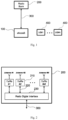
- Fig. 1 illustrates the components of a cell, which is a building block of a typical cellular network.
- the wireless terminals 400 called User Equipment (UE) are connected via wireless links (not shown in Fig. 1 ) to a base station comprising processor 100 called eNodeB, Radio Interface Bus 300 and Radio Bank 200.
- the UEs may be mobile devices such as cell phones, tablets, car phones, etc. or stationary devices such as computers, monitoring stations, security devices, etc.
- the wireless links between the base station and the UEs are generated and are managed by the base station radios in the Radio Bank 200 and by radios inside the UEs.
- the processor eNodeB 100 connects to other nodes in the cellular network via communication links called backhaul.
- the Radio Bank 200 shown in more details in Fig. 2 , contains M radio Transmit/Receive modules (Tx/Rx Modules) 210, where M is an integer, a Radio Digital Interface 230, and M Internal Buses 220.
- the processor 100 transmits and receives digital signals from and to each Tx/Rx Module 210 via the Radio Interface Bus 300 and the Internal Buses 220.
- M is 1-4, but systems with larger number of radios are possible.
- a simplified Tx/Rx Module 210 is shown in Fig. 3 .
- the main functions of this module are to convert digital signals into radio frequency (RF) signals and vice versa and to couple the RF signals to and from the antenna.
- the transmitter part of the Tx/Rx Module includes a digital-to-analog (DAC) converter and a frequency Up-Converter while the receiver part of the Tx/Rx Module includes a frequency Down-Converter and an analog-to-digital (ADC) converter.
- a Digital Duplexer connects the transmit/receive paths to the Internal Bus 220 and an RF Front-End connects the transmit/receive paths to the antenna.
- the RF Front-End contains a receiver low noise amplifier, a transmitter power amplifier, and several RF filters and switches.
- the cell wireless traffic over a certain period is the total amount of information (e.g., measured in bits) flowing during that period between all UEs serviced by the base station and the respective base station.
- There is a downstream cell traffic i.e., data flowing from the base station to the UEs
- an upstream cell traffic i.e., the data flowing from the UEs to the base station.
- FDD Frequency Division Duplexing
- TDD Time Division Duplexing
- the resulting cell traffic value divided by the respective period is a good approximation of the instantaneous cell traffic bit-rate (e.g. measured in bits-per-second) or simply "cell rate" at any time within that period.
- the upstream cell rate is different from the downstream cell rate and each varies widely in time. For example, during night hours, they are usually low and may even go to zero occasionally but at busy day hours, they reach much higher values.
- the cell rates may change very rapidly. For example, a base station covering a highway would experience a sudden increase in data flow when a road traffic jam forces many cars to a full stop, motivating drivers and passengers to use their phones. Similarly, the end of a sports or music event in a public arena typically triggers a large peak in the cell rate for the base station covering that area.
- a sector rate upstream and downstream
- the traffic bit rate the base station uses to communicate with the mobiles in a sector since the instantaneous cell/sector rate can vary quickly and by large amounts, it is useful to also consider the average cell/sector rates calculated or measured over a certain period.
- the instantaneous sector rate handled by a base station may vary widely between 0.1 bits/Hz to 1 bits/Hz over one hour but the average cell rate may be 0.2 bits/Hz, assuming most of the time during that hour the instantaneous cell rate is closer to the lower bound.
- the instantaneous and average cell rates are the sums of the respective sector rates because the base station handles the sectors simultaneously (separate radio per each sector). Therefore, it is sufficient to discuss sector rates, as all arguments and conclusions are also valid for cell rates.
- the instantaneous sector rate can be only as high as a maximum value given by the wireless standard and the EM bandwidth used.
- the typical communication protocols of wireless systems specify a finite set of data rates (downstream and upstream) allowed for communication between the base station and UEs.
- the actual data rate used at any time for each UE depends on the respective wireless link quality and is set by the base station dynamically. For example, if the SNIR of a link is smaller than a certain minimum number, the base station does not initiate any data transfers with the UE. If the link SNIR is higher than the minimum but less than the next higher level, the base station initiates the data exchange at the minimum specified rate.
- each rate corresponding to a SNIR band, up to a maximum rate.
- the SNIR band for the top rate is unbounded, i.e., any increase in SNIR does not result in higher data rates.
- the sector instantaneous rate reaches a maximum. At this time, the base station or the cell traffic are said to reach "peak capacity".
- the peak spectrum efficiency is the maximum sector rate divided by the EM bandwidth.
- the average spectrum efficiency is the average sector rate divided by the EM bandwidth.
- the peak and average spectrum efficiencies are measured in bits-per-second-per-Hertz (b/s/Hz).
- the low SNIR conditions producing low average sector rates compared to the peak rate also produce low average spectrum efficiency compared to the peak spectrum efficiency.
- Fig. 7 shows the case of attempting to boosts the local SNIR with wedge beams 503, which are narrow in azimuth but wide in elevation. These beams, also known as 2D beams, are not as effective as pencil (3D) beams in raising the sector average spectral efficiency when most UEs are grouped in small areas.
- the conventional base station antennas produce directional radiation patterns or beams that cover the entire 120-degree sector and are minimum (ideally zero) outside the sector. For the purpose of this specification, these beams are called "wide".
- An antenna radiation pattern that would cover only a small portion of the conventional 120-degree cellular sector (e.g., one-tenth of the sector or smaller area) if used instead of the regular wide beam is called a "narrow" beam.
- Such narrow beams can be generated with dish antennas or two-dimensional antenna arrays.
- Typical conventional sector antennas generating a wide beam are built with one or few vertical columns of antenna elements, each element radiating in a beam wider than the 120-degree sector.
- a network of cables and phase shifters feeds these antenna elements from a single radio frequency (RF) input such that the overall radiation pattern of the sector antenna, which is the superposition of the beams from all the antenna elements, is contained almost fully within the 120-degree sector.
- RF radio frequency
- the wide beam thus created covers the sector with non-uniform SNIR at ground level, which is maximum somewhere inside the sector far from the sector boundaries and much smaller at the sector boundaries. This is necessary to minimize mutual interference between adjacent sectors and cells.
- the SNIR distribution from a sector antenna will not match the UE distribution resulting in small sector spectrum efficiency.
- the spectrum efficiency gets even lower.
- the use of conventional sector antennas with fixed wide beams is non-optimum for spectrum efficiency. This further explains the low average spectrum efficiency experienced in practice by most sectors.
- a modest improvement of this situation is achieved by using mechanical/electrical tilt, rotation, and fanning technologies.
- the antennas are designed with mechanical or electromechanical means to change the position of the peak SNIR projection on the ground further or closer to the tower by tilting the antenna radiation pattern in elevation.
- Some of these antennas called RET (Remote Electrical Tilt) can be adjusted electrically from distance.
- a common RET design is with electrical motors placed on the antenna body to actuate a mechanism, which changes the electrical properties of the RF feed network to the antenna elements such as to accomplish the desired effect.
- Similar electromechanical designs can produce physical rotations of the entire antenna body in azimuth called panning and fanning effects, i.e. changing the beam width in azimuth.
- a precise way of describing the antenna radiation pattern is by considering the angle of departure (AOD) of plane waves propagating from the antenna.
- AOD angle of departure
- any 3-dimensional antenna radiation pattern transmitted can be decomposed into a superposition of plane waves, each carrying a portion of the antenna electro-magnetic (EM) power on various AODs.
- EM electro-magnetic
- These plane waves are also called "rays".
- the strengths of these rays vary with the AOD and become negligible or zero outside a solid angle on which the antenna is designed to focus.
- the AODs of all rays with non-negligible energy form a solid angle as large as the visual field of the sector from the antenna position on the tower.
- Some cellular antennas are designed to create narrower beams for coverage of smaller areas than standard 120-degre sectors.
- antennas are built as reciprocal electrical systems, i.e., they have identical transmit and receive radiation patterns. Therefore, for each plane wave transmitted at an AOD, a corresponding identical plane wave can be received at an angle of arrival (AOA) equal to the respective AOD.
- AOA angle of arrival
- Antenna gain along a certain AOD is defined as the ratio between the power of the transmitted ray in the respective AOD and the power of a hypothetical transmitted ray in any direction from a hypothetical antenna radiating equally in all directions (isotropic radiation) the same total EM power as the antenna under consideration.
- antenna gain is measured in decibels (dB), in accordance with the usual practice for power ratios.
- the dB unit of antenna gain is called decibels-isotropic or "dBi”.
- the antenna elements used in sector antennas have 3-6 dBi maximum gains. Typical 120-degree sector antennas with 12 elements have 15-17 dBi maximum gains. Planar arrays with 96 antenna elements (e.g., 12x8) have about 25 dBi maximum gain.
- Dish antennas used in microwave point-to-point links have maximum gains as high as 30-40 dBi.
- a beam is the antenna radiation pattern inside a specific solid angle having the vertex at the center of the antenna and satisfying three conditions. These conditions are: a) the direction with maximum antenna gain is inside this solid angle, b) the antenna gains in all other directions within this solid angle are smaller than the maximum gain by no more than 3dB, and c) the antenna gains in all directions outside this solid angle are smaller than the maximum gain by more than 3dB.
- the direction for maximum gain defines the beam direction.
- the wide beams generated by conventional cellular antennas contain rays with a large AOD variation.
- LOS line-of sight
- only a group of rays with close AODs reaches each UE.
- the signal loss to each UE is large due to transmitted energy dispersion in a wide solid angle, but there is little or no multi-path fading as all rays reaching any UE have almost identical paths.
- NLOS non-line-of sight
- several groups of rays reach each UE, typically. Within each group, the rays have similar paths but rays from different groups have rather dissimilar paths. This produces strong multi-path fading in addition to loss. Loss and fading are detrimental effects for the SNIR in the sector.
- Narrow beams can be created by several methods including using two-dimensional arrays of radiating (antenna) elements.
- the rays in narrow beams have only a small variation in AOD, naturally. Consequently, these rays propagate through similar paths in LOS or NLOS situations and in sectors with or without clutter.
- the loss in narrow beams is smaller than in wide beams due to less spatial dispersion and the multi-path fading is reduced due to fewer dissimilar paths reaching the UEs.
- the direction of a beam is the direction considered from the antenna position, for which the antenna gain is maximum. Stated in an equivalent manner, the beam "points" in a direction, which is the direction with maximum antenna gain.
- the direction of a beam can be changed by purely mechanical means, by mixed mechanical and electrical means, or by purely electrical means.
- conventional sector antennas are mounted on cellular towers with mechanical fixtures that allow adjustment of the antenna elevation angle or tilt such that the antenna wide beam points at a convenient place in the sector.
- This purely mechanical way for pointing the beam is limited to very rare adjustments.
- the RET antennas provide an example of beam pointing adjustment in elevation by mixed mechanical and electrical means, as described earlier. The beam direction adjustment of these antennas can be performed often, albeit slowly.
- Phased arrays such as those used in RADARs generate narrow 3D beams that can be pointed in many directions very rapidly by purely electrical means. Moving the beam direction of phased arrays, also known as “beam steering", is achieved by changing the phases of the signals applied to the antenna elements. In general, phased arrays can generate multiple independent narrow beams, that are independently steerable. For this reason, phased arrays are suitable for use as infrastructure antennas in wireless communications systems as they can create non-uniform SNIR patterns on the ground with small areas where SNIR values are high. This was shown earlier to be an effective method for increasing the average spectrum efficiency when the wireless traffic pattern is non-uniform.
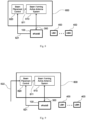
- Fig. 8 shows the components of a cell in a typical cellular network with the Radio Bank 200 from Fig. 1 replaced by a more complex radio bank 600 called BFS Radio Bank, which adds beamforming and beam steering functions.
- the internal Beam Forming Active Antenna System 610 provides beam forming and the internal Beam Placement Control 620 provides beam steering. If the Beam Forming Active Antenna System 610 is a phased array, the Beam Placement Control 620 provides phase and magnitude values for the signals transmitted or received by 610.
- the eNodeB 100 controls the pointing direction of the beam and the respective beam placement on the ground via appropriate control signals sent over control line 621.
- These control signals may be simple codes corresponding to various predetermined beam positions. In this case, all phase and magnitude information for beam forming is already present in the BFS radio bank 600.
- Another example of control signals is the entire set of phase and magnitude numbers needed by the Beam Forming Active Antenna System 610 to create beams.
- the Beam Placement Control block 620 controls the Beam Forming Active Antenna System 610 via an internal control line 611.
- the base station in Fig. 8 comprising eNodeB 100, Radio Interface Bus 300, BFS Radio Bank 600, and control line 621 requires an additional functionality not necessary in the base station in Fig. 1 (blocks 100, 300, and 600) in order to select the directions of the beams generated by the BFS Radio Bank.
- the placement of these beams has important consequences for the sector average spectrum efficiency when the wireless traffic is non-uniform. Therefore, it is important to find the optimum beam placement to obtain as high average spectrum efficiency as possible. Furthermore, this optimum beam placement must be changed adaptively to match the traffic pattern.
- the eNodeB has detailed SNIR and data rate information for every link to the UE 400 it serves. Therefore, the eNodeB can calculate the instantaneous and average spectrum efficiencies at any time. Moreover, the eNodeB can record the history of these parameters and analyze their statistics over the hours of the day and over longer periods including seasonal changes. Such recordings and analysis may be done automatically or in combination with human intervention. In addition, correlations between these statistics and the physical locations of the UEs can be performed. The eNodeB has several means to find the physical locations of UEs such as GPS coordinate reporting by UEs or triangulation techniques. The final goal of such statistical calculations is to generate maps of traffic patterns and direct the beams such as to match the traffic patterns with similar SNIR patterns.
- a method to obtain traffic pattern maps quickly and easily is by using a narrow beam such as generated by a phased array.
- This beam scans slowly the entire sector while the eNodeB calculates the spectrum efficiency in the area covered by this beam for each beam position. After one or several such scans, the eNodeB determines the directions for which the beam increases the spectrum efficiency, i.e. the directions where the wireless traffic is clustered, e.g. directions in which communications density experiences peaks or maximums. Then, the eNodeB directs all available beams in as many directions with high traffic as possible. The same procedure could be done at different times of the day and on different days of the year to generate traffic pattern maps. After these maps are available, the beam placement could be programed without further calculations. However, if the average spectrum efficiency deteriorates, the traffic maps must be updated with the same procedure as before.
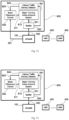
- the base station in Fig. 8 is fully responsible for beam placing, according to the methods described above or similar. However, it is possible to design the Beam Placement Control 620 with control lines 622 in addition to control lines 621, as shown in Fig. 9 . In this case, a system other than the base station could form and point the beams.
- the method of beam scanning with spectrum efficiency monitoring as well as the methods of statistical calculations for generating traffic maps described above are examples of a general class of methods for detecting the traffic density in the sector.
- a hardware, firmware, software or any mix thereof supporting such a method is called a "Traffic Density Detector".
- the base station in Fig. 8 implicitly contains an eNodeB-based Traffic Density Detector to determine the correct placement of the beams.
- an External Traffic Density Detector 700 In order for the system in Fig. 9 to operate properly, an External Traffic Density Detector 700 must be connected as in Fig. 10 .
- An example of External Traffic Density Detector is an independent server (not part of eNodeB) receiving link quality and data rate values from software running in UEs. The reported information could be instantaneous values or averages over a period.
- the UEs communicate with the server via the standard channels just like a regular client of the cellular system.
- the placement of the beams is under control of both the eNodeB and the External Traffic Density Detector as in Fig. 10 , care must be taken to avoid unstable operational loops when eNodeB and the External Traffic Density Detector attempt to steer the beams against each other.
- a solution to this potential problem is to assign the eNodeB and the External Traffic Density Detector the control of different beams.
- the eNodeB may be programmed to place a few beams in several known locations with high traffic at various times of the day and an External Traffic Density Detector may be used for additional beam placements when unpredictable high traffic density occurs in portions of the sector.
- Fig. 11 shows a system in which the eNodeB is connected to the BFS Radio Bank 600 only via the Radio Interface Bus 300.
- the External Traffic Density Detector 700 performs all beam control functionality in the system. This configuration is important in practice for retrofitting the conventional system of Fig. 1 with a BFS Radio Bank and introducing optimum beamforming and steering functionality (to get high spectrum efficiency) without any changes in the eNodeB but simply by adding an External Traffic Density Detector.
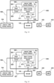
- Fig. 12 illustrates the possibility of using a Traffic Density Detector, which resides inside the BFS Radio Bank 600 called Internal Traffic Density Detector 640.
- This block controls the Beam Placement Control block 620 via an internal line 623.
- the Internal Traffic Density Detector requires a source of information about the wireless traffic. The only such source available inside the BFS Radio Bank is the Radio Interface Bus 300. In fact, the complete information regarding all cellular traffic for this base station passes through the Radio Interface Bus 300.
- a signal splitter 630 is necessary to tap this information and send it to the Internal Traffic Density Detector 640 via the line 641.
- the splitter 630 also connects to the Beam Forming Active Antenna System 610 via the line 631.
- Extracting traffic patterns from the Radio Interface Bus signals is a complex operation, which may be performed in the eNodeB, as described earlier. Therefore, an example of Internal Traffic Density detector is a replica of the minimum functionality in the eNodeB to detect traffic patterns. However, simpler methods are available such as monitoring the density of raw radio data flowing through the Radio Interface Bus.
- Figs. 13 , 14 and 15 show various system configurations in which the beam placement control is provided by various combinations of Internal and External Traffic Density Detectors and eNodeB.
- the description of the corresponding components in the previously illustrated embodiments applies as well to these figures.
- appropriate planning of control is necessary to avoid conflicts between the various Traffic Density Detectors.
- a multiple beam phased array that is situated in a geographical area for which cellular communications is being provided generates multiple steerable beams directed to areas of concentration of demand density.
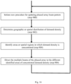
- the system initiates the process for updating the positions of the multiple communication beams that are generated by the array (step 800).
- the system obtains the most up-to-date information on that demand density (step 802). That may be accomplished by referring to stored information reflecting historical data indicative of measured demand density for the corresponding time slot or by obtaining a direct measurement of the demand density at that time, either from external sources or internally from data that is collected by the base station during operation. (Refer to the different approaches described in greater detail above.)
- the system Upon determining the geographical or spatial distribution of demand density for that time period, the system identifies the areas of greatest demand or the areas in which demand is concentrated (step 804) and then it directs individual communication beams to service those areas (step 806).
- this process is repeated to steer the beams to other more appropriate areas based upon the change in the geographical or spatial distribution of demand density at that later time.
- This process can be performed on regular intervals or at predetermined irregular times. If the system is operating in an environment in which demand density varies continually, updating the system at regular intervals might be appropriate. On the other hand, if historical data indicates that significant changes in demand density typically occur at certain times of the day or week or month, then the system can be programmed to execute the updating procedure at those particular times.
Landscapes
- Engineering & Computer Science (AREA)
- Computer Networks & Wireless Communication (AREA)
- Signal Processing (AREA)
- Databases & Information Systems (AREA)
- Mobile Radio Communication Systems (AREA)
- Computer Security & Cryptography (AREA)
Claims (8)
- Verfahren zum Betreiben einer Phased-Array-Antenne (610) für ein drahtloses Kommunikationssystem, das einen Dienstbereich bedient, in dem sich die Kommunikationsanforderungen einer Vielzahl mobiler Kommunikationsvorrichtungen (400) in Abhängigkeit von der Zeit ändern, wobei das Verfahren umfasst:für jeden Zeitabschnitt einer Vielzahl aufeinanderfolgender Zeitabschnitte,(1) Erhalten von Informationen, die eine Anforderungsdichte für Mobilkommunikation in Abhängigkeit von der Strahlrichtung für diesen Zeitraum (802) angeben, indem ein Sondenstrahl über den Dienstbereich gescannt wird, und während des Scannens des Sondenstrahls über den Dienstbereich die Spektrumeffizienz bestimmt wird, die ein Maß für die Anzahl der in einer Zeiteinheit über eine verwendete feste Bandbreite übertragenen Bits in Abhängigkeit von der Sondenstrahlrichtung ist;(2) Verwenden der Spektrumeffizienz in Abhängigkeit von der Sondenstrahlrichtung, um die erhaltenen Informationen für diesen Zeitraum bereitzustellen(3) Verwenden der erhaltenen Informationen zum Identifizieren einer Strahlrichtung, für die die Anforderungsdichte der Mobilkommunikation zu diesem Zeitpunkt im Vergleich zu anderen Richtungen hoch ist (804); und(4) mit der Phased-Array-Antenne elektronisches Erzeugen eines Kommunikationsstrahl, der in die identifizierte Richtung gerichtet ist, für die die gesamte Mobilkommunikationsanforderungsdichte für diesen Zeitraum im Vergleich zu anderen Strahlrichtungen hoch ist (806),wobei der Sondenstrahl ein schmaler Strahl ist, und wobei der Kommunikationsstrahl ein schmaler Strahl ist.
- Verfahren nach Anspruch 1, wobei das Scannen des Sondenstrahls über dem Dienstbereich das Scannen des Sondenstrahls über einen Bereich von Richtungen umfasst, wobei der Bereich von Richtungen, über den der Sondenstrahl gescannt wird, sowohl im Azimut als auch in der Höhe variiert.
- Verfahren nach Anspruch 1, wobei der Kommunikationsstrahl eine Form aufweist, die auf der Grundlage von Details bezüglich der Clusterung der gesamten Mobilkommunikationsanforderungsdichte ausgewählt wird.
- Verfahren nach Anspruch 1, wobei der erzeugte Kommunikationsstrahl ein Übertragungsstrahl ist.
- Verfahren nach Anspruch 1, wobei der erzeugte Kommunikationsstrahl ein Empfangsstrahl ist.
- Verfahren nach Anspruch 1, ferner umfassend:
mit der Phased-Array-Antenne (610), und für jeden Zeitpunkt der Vielzahl von aufeinanderfolgenden Zeiträumen elektronisches Erzeugen einer Vielzahl von Kommunikationsstrahlen, die jeweils in eine Vielzahl von unterschiedlichen Richtungen gerichtet sind, für die die Anforderungsdichte an mobiler Kommunikation zu diesem Zeitpunkt relativ zu anderen Strahlrichtungen hoch ist, wobei der erstgenannte Kommunikationsstrahl zu der Vielzahl von Kommunikationsstrahlen gehört. - Verfahren nach Anspruch 1, ferner umfassend:
mit der Phased-Array-Antenne (610), und für jeden Zeitpunkt der Vielzahl von aufeinanderfolgenden Zeitpunkten, elektronisches Erzeugen einer Vielzahl von Kommunikationsstrahlen, die jeweils in eine Vielzahl von unterschiedlichen Richtungen gerichtet sind, für die die Anforderungsdichte der mobilen Kommunikation eine Clusterung aufweist, wobei der erstgenannte Kommunikationsstrahl zu der Vielzahl von Kommunikationsstrahlen gehört. - Verfahren nach Anspruch 7, wobei die Formen der Kommunikationsstrahlen der Vielzahl von Kommunikationsstrahlen so ausgewählt werden, dass sie den Formen der Cluster entsprechen.
Applications Claiming Priority (2)
| Application Number | Priority Date | Filing Date | Title |
|---|---|---|---|
| US201462025638P | 2014-07-17 | 2014-07-17 | |
| PCT/US2015/040565 WO2016011151A1 (en) | 2014-07-17 | 2015-07-15 | Method for adaptive beam placement in wireless systems |
Publications (2)
| Publication Number | Publication Date |
|---|---|
| EP3170332A1 EP3170332A1 (de) | 2017-05-24 |
| EP3170332B1 true EP3170332B1 (de) | 2024-11-20 |
Family
ID=53761567
Family Applications (1)
| Application Number | Title | Priority Date | Filing Date |
|---|---|---|---|
| EP15742502.6A Active EP3170332B1 (de) | 2014-07-17 | 2015-07-15 | Verfahren zur adaptiven strahlplatzierung in drahtlosen systemen |
Country Status (6)
| Country | Link |
|---|---|
| US (1) | US20160021650A1 (de) |
| EP (1) | EP3170332B1 (de) |
| JP (1) | JP6900311B2 (de) |
| KR (1) | KR20170036722A (de) |
| CN (1) | CN106576254B (de) |
| WO (1) | WO2016011151A1 (de) |
Families Citing this family (18)
| Publication number | Priority date | Publication date | Assignee | Title |
|---|---|---|---|---|
| US10484899B2 (en) * | 2015-04-06 | 2019-11-19 | Lg Electronics Inc. | Mobility management for high speed user equipment |
| US9667290B2 (en) * | 2015-04-17 | 2017-05-30 | Apple Inc. | Electronic device with millimeter wave antennas |
| US9867080B2 (en) * | 2016-03-31 | 2018-01-09 | T-Mobile Usa, Inc. | Determining network congestion based on target user throughput |
| JP6216425B1 (ja) * | 2016-09-01 | 2017-10-18 | パナソニック株式会社 | 基地局装置、通信システムおよび送信制御方法 |
| US10181943B2 (en) * | 2016-09-29 | 2019-01-15 | Blue Danube Systems, Inc. | Distributing coherent signals to large electrical distances over serial interconnections |
| US10999824B2 (en) * | 2016-09-30 | 2021-05-04 | Telefonaktiebolaget Lm Ericsson (Publ) | Methods and apparatuses for handling of retransmission feedback |
| WO2019069395A1 (en) | 2017-10-04 | 2019-04-11 | Nec Corporation | REMOTE RADIO HEAD, BEAM FORMING METHOD, AND INFORMATION CARRIER |
| WO2019069410A1 (en) | 2017-10-04 | 2019-04-11 | Nec Corporation | REMOTE RADIO HEAD, BEAM FORMING METHOD, AND STORAGE MEDIUM |
| US10291315B1 (en) * | 2018-06-04 | 2019-05-14 | Asia Satellite Telecommunications Company Limited | Methods and systems for operating a high throughput satellite |
| WO2019233830A1 (en) * | 2018-06-06 | 2019-12-12 | Sony Corporation | Coexistence of radar probing and wireless communication |
| US11196470B2 (en) | 2018-10-15 | 2021-12-07 | Blue Danube Systems, Inc. | Enhancing throughput using agile beam switching and user scheduling in cellular systems |
| US11169240B1 (en) | 2018-11-30 | 2021-11-09 | Ball Aerospace & Technologies Corp. | Systems and methods for determining an angle of arrival of a signal at a planar array antenna |
| CN109587802B (zh) * | 2019-01-21 | 2020-11-24 | 中国电子科技集团公司第二十九研究所 | 一种基于相控阵捷变波束的上行信道资源分配方法 |
| US10805829B2 (en) | 2019-02-08 | 2020-10-13 | Cisco Technology, Inc. | BLE-based location services in high density deployments |
| US11327142B2 (en) | 2019-03-29 | 2022-05-10 | Ball Aerospace & Technologies Corp. | Systems and methods for locating and tracking radio frequency transmitters |
| WO2021114185A1 (en) * | 2019-12-12 | 2021-06-17 | Telefonaktiebolaget Lm Ericsson (Publ) | Methods and apparatuses for ret control |
| KR20220081759A (ko) | 2020-12-09 | 2022-06-16 | 삼성전자주식회사 | 무선 통신 시스템에서 안테나를 제어하기 위한 장치 및 방법 |
| JP2024529807A (ja) * | 2021-07-29 | 2024-08-14 | ジオ プラットフォームズ リミティド | 対流圏干渉を検出及び軽減するための方法及びシステム |
Citations (2)
| Publication number | Priority date | Publication date | Assignee | Title |
|---|---|---|---|---|
| US20050272472A1 (en) * | 2004-05-27 | 2005-12-08 | Interdigital Technology Corporation | Wireless communication method and system for forming three-dimensional control channel beams and managing high volume user coverage areas |
| US20120196591A1 (en) * | 2008-07-06 | 2012-08-02 | O'keeffe Conor | Wireless network element and method for antenna array control |
Family Cites Families (15)
| Publication number | Priority date | Publication date | Assignee | Title |
|---|---|---|---|---|
| AU3685200A (en) * | 1999-02-26 | 2000-09-14 | Telefonaktiebolaget Lm Ericsson (Publ) | Smart antenna beam assignment at mobile station hand-off |
| US6697644B2 (en) * | 2001-02-06 | 2004-02-24 | Kathrein-Werke Kg | Wireless link quality using location based learning |
| JP2003283418A (ja) * | 2002-03-26 | 2003-10-03 | Matsushita Electric Ind Co Ltd | 基地局装置および送受信方法 |
| US20060068848A1 (en) * | 2003-01-28 | 2006-03-30 | Celletra Ltd. | System and method for load distribution between base station sectors |
| JP5049045B2 (ja) * | 2007-04-17 | 2012-10-17 | 京セラ株式会社 | 基地局装置および共通制御信号送信方法 |
| US8494588B2 (en) * | 2007-07-06 | 2013-07-23 | Telefonaktiebolaget Lm Ericsson (Publ) | Method and apparatus for improving the performance of a mobile radio communications system by adjusting antenna patterns |
| JP5258444B2 (ja) * | 2007-09-28 | 2013-08-07 | 株式会社エヌ・ティ・ティ・ドコモ | 基地局装置、移動端末、及び周波数共用方法 |
| US8385978B2 (en) * | 2009-05-22 | 2013-02-26 | Fimax Technology Limited | Multi-function wireless apparatus |
| US8842525B2 (en) * | 2009-10-08 | 2014-09-23 | Clearwire Ip Holdings Llc | System and method for extending a wireless communication coverage area of a cellular base transceiver station (BTS) |
| US8611959B2 (en) | 2010-07-01 | 2013-12-17 | Blue Danube Labs, Inc. | Low cost, active antenna arrays |
| CN102378205B (zh) * | 2010-08-13 | 2015-04-08 | 华为技术有限公司 | 微小区创建方法及基站 |
| US8559976B2 (en) * | 2010-11-09 | 2013-10-15 | Ntt Docomo, Inc. | System and method for population tracking, counting, and movement estimation using mobile operational data and/or geographic information in mobile network |
| WO2012139101A1 (en) * | 2011-04-07 | 2012-10-11 | Blue Danube Labs, Inc. | Techniques for achieving high average spectrum efficiency in a wireless system |
| US8750896B2 (en) * | 2011-10-13 | 2014-06-10 | At&T Mobility Ii Llc | Femtocell measurements for macro beam steering |
| US9609648B2 (en) * | 2014-06-16 | 2017-03-28 | Qualcomm Incorporated | Beamform scheduling based on the directionality of UEs |
-
2015
- 2015-07-15 CN CN201580038786.9A patent/CN106576254B/zh active Active
- 2015-07-15 KR KR1020177004520A patent/KR20170036722A/ko not_active Ceased
- 2015-07-15 WO PCT/US2015/040565 patent/WO2016011151A1/en not_active Ceased
- 2015-07-15 EP EP15742502.6A patent/EP3170332B1/de active Active
- 2015-07-15 JP JP2017501380A patent/JP6900311B2/ja not_active Expired - Fee Related
- 2015-07-15 US US14/799,935 patent/US20160021650A1/en not_active Abandoned
Patent Citations (2)
| Publication number | Priority date | Publication date | Assignee | Title |
|---|---|---|---|---|
| US20050272472A1 (en) * | 2004-05-27 | 2005-12-08 | Interdigital Technology Corporation | Wireless communication method and system for forming three-dimensional control channel beams and managing high volume user coverage areas |
| US20120196591A1 (en) * | 2008-07-06 | 2012-08-02 | O'keeffe Conor | Wireless network element and method for antenna array control |
Also Published As
| Publication number | Publication date |
|---|---|
| EP3170332A1 (de) | 2017-05-24 |
| KR20170036722A (ko) | 2017-04-03 |
| US20160021650A1 (en) | 2016-01-21 |
| WO2016011151A1 (en) | 2016-01-21 |
| JP6900311B2 (ja) | 2021-07-07 |
| JP2017528031A (ja) | 2017-09-21 |
| CN106576254A (zh) | 2017-04-19 |
| CN106576254B (zh) | 2020-12-25 |
Similar Documents
| Publication | Publication Date | Title |
|---|---|---|
| EP3170332B1 (de) | Verfahren zur adaptiven strahlplatzierung in drahtlosen systemen | |
| EP0647979B1 (de) | Antenneneinrichtung für Basisstation | |
| US8519902B2 (en) | Wireless local area network antenna array | |
| US5771017A (en) | Base station antenna arrangement | |
| US5576717A (en) | Base station antenna arrangement | |
| JP2003060423A (ja) | スマートアンテナアレイ | |
| GB2376567A (en) | Smart antenna array basestation | |
| JPH11502986A (ja) | 広角度アンテナローブ | |
| GB2281175A (en) | Base station antenna arrangement | |
| MXPA05001234A (es) | Red de dimension tridimensional para transmision celular. | |
| GB2281010A (en) | Base station antenna arrangement | |
| US5570098A (en) | Base station antenna arrangement | |
| Li et al. | 5g in the sky: the future of high-speed internet via unmanned aerial vehicles | |
| KR20050027896A (ko) | 주파수 옵셋을 이용하여 스마트 안테나의 빔을 제어하는방법 및 시스템 | |
| US12074676B2 (en) | Beamforming codebook synthesis in a wireless communications system (WCS) | |
| GB2281008A (en) | Base station antenna arrangement | |
| Kumar et al. | 2D active antenna array design for mMIMO to improve spectral and energy efficiency | |
| US9666933B2 (en) | Wireless local area network antenna array | |
| US20250142355A1 (en) | Beamforming coverage optimization in a radio access network in a wireless communications system (wcs) | |
| WO2025042595A2 (en) | Reconfigurable intelligent surface (ris) circuit in a wireless communications system (wcs) | |
| EP2693566B1 (de) | Antennenvorrichtung | |
| UOY et al. | Report on adaptive beamforming algorithms for advanced antenna types for aerial platform and ground terminals | |
| Ahmed et al. | A Survey on Millimeter-Wave for 5G Mobile Systems | |
| WO2006096866A2 (en) | Wireless local area network antenna array |
Legal Events
| Date | Code | Title | Description |
|---|---|---|---|
| STAA | Information on the status of an ep patent application or granted ep patent |
Free format text: STATUS: THE INTERNATIONAL PUBLICATION HAS BEEN MADE |
|
| PUAI | Public reference made under article 153(3) epc to a published international application that has entered the european phase |
Free format text: ORIGINAL CODE: 0009012 |
|
| STAA | Information on the status of an ep patent application or granted ep patent |
Free format text: STATUS: REQUEST FOR EXAMINATION WAS MADE |
|
| 17P | Request for examination filed |
Effective date: 20170216 |
|
| AK | Designated contracting states |
Kind code of ref document: A1 Designated state(s): AL AT BE BG CH CY CZ DE DK EE ES FI FR GB GR HR HU IE IS IT LI LT LU LV MC MK MT NL NO PL PT RO RS SE SI SK SM TR |
|
| AX | Request for extension of the european patent |
Extension state: BA ME |
|
| DAV | Request for validation of the european patent (deleted) | ||
| DAX | Request for extension of the european patent (deleted) | ||
| STAA | Information on the status of an ep patent application or granted ep patent |
Free format text: STATUS: EXAMINATION IS IN PROGRESS |
|
| 17Q | First examination report despatched |
Effective date: 20181212 |
|
| P01 | Opt-out of the competence of the unified patent court (upc) registered |
Effective date: 20230601 |
|
| RAP3 | Party data changed (applicant data changed or rights of an application transferred) |
Owner name: NEC ADVANCED NETWORKS, INC. |
|
| GRAP | Despatch of communication of intention to grant a patent |
Free format text: ORIGINAL CODE: EPIDOSNIGR1 |
|
| STAA | Information on the status of an ep patent application or granted ep patent |
Free format text: STATUS: GRANT OF PATENT IS INTENDED |
|
| RIC1 | Information provided on ipc code assigned before grant |
Ipc: H04W 24/02 20090101ALI20240530BHEP Ipc: H04W 16/28 20090101AFI20240530BHEP |
|
| INTG | Intention to grant announced |
Effective date: 20240613 |
|
| RIC1 | Information provided on ipc code assigned before grant |
Ipc: H04W 24/02 20090101ALI20240603BHEP Ipc: H04W 16/28 20090101AFI20240603BHEP |
|
| GRAS | Grant fee paid |
Free format text: ORIGINAL CODE: EPIDOSNIGR3 |
|
| GRAA | (expected) grant |
Free format text: ORIGINAL CODE: 0009210 |
|
| STAA | Information on the status of an ep patent application or granted ep patent |
Free format text: STATUS: THE PATENT HAS BEEN GRANTED |
|
| AK | Designated contracting states |
Kind code of ref document: B1 Designated state(s): AL AT BE BG CH CY CZ DE DK EE ES FI FR GB GR HR HU IE IS IT LI LT LU LV MC MK MT NL NO PL PT RO RS SE SI SK SM TR |
|
| REG | Reference to a national code |
Ref country code: GB Ref legal event code: FG4D |
|
| REG | Reference to a national code |
Ref country code: CH Ref legal event code: EP |
|
| REG | Reference to a national code |
Ref country code: DE Ref legal event code: R096 Ref document number: 602015090455 Country of ref document: DE |
|
| REG | Reference to a national code |
Ref country code: IE Ref legal event code: FG4D |
|
| REG | Reference to a national code |
Ref country code: LT Ref legal event code: MG9D |
|
| REG | Reference to a national code |
Ref country code: NL Ref legal event code: MP Effective date: 20241120 |
|
| PG25 | Lapsed in a contracting state [announced via postgrant information from national office to epo] |
Ref country code: IS Free format text: LAPSE BECAUSE OF FAILURE TO SUBMIT A TRANSLATION OF THE DESCRIPTION OR TO PAY THE FEE WITHIN THE PRESCRIBED TIME-LIMIT Effective date: 20250320 Ref country code: PT Free format text: LAPSE BECAUSE OF FAILURE TO SUBMIT A TRANSLATION OF THE DESCRIPTION OR TO PAY THE FEE WITHIN THE PRESCRIBED TIME-LIMIT Effective date: 20250320 Ref country code: HR Free format text: LAPSE BECAUSE OF FAILURE TO SUBMIT A TRANSLATION OF THE DESCRIPTION OR TO PAY THE FEE WITHIN THE PRESCRIBED TIME-LIMIT Effective date: 20241120 |
|
| PG25 | Lapsed in a contracting state [announced via postgrant information from national office to epo] |
Ref country code: FI Free format text: LAPSE BECAUSE OF FAILURE TO SUBMIT A TRANSLATION OF THE DESCRIPTION OR TO PAY THE FEE WITHIN THE PRESCRIBED TIME-LIMIT Effective date: 20241120 Ref country code: NL Free format text: LAPSE BECAUSE OF FAILURE TO SUBMIT A TRANSLATION OF THE DESCRIPTION OR TO PAY THE FEE WITHIN THE PRESCRIBED TIME-LIMIT Effective date: 20241120 |
|
| REG | Reference to a national code |
Ref country code: AT Ref legal event code: MK05 Ref document number: 1744662 Country of ref document: AT Kind code of ref document: T Effective date: 20241120 |
|
| PG25 | Lapsed in a contracting state [announced via postgrant information from national office to epo] |
Ref country code: BG Free format text: LAPSE BECAUSE OF FAILURE TO SUBMIT A TRANSLATION OF THE DESCRIPTION OR TO PAY THE FEE WITHIN THE PRESCRIBED TIME-LIMIT Effective date: 20241120 |
|
| PG25 | Lapsed in a contracting state [announced via postgrant information from national office to epo] |
Ref country code: ES Free format text: LAPSE BECAUSE OF FAILURE TO SUBMIT A TRANSLATION OF THE DESCRIPTION OR TO PAY THE FEE WITHIN THE PRESCRIBED TIME-LIMIT Effective date: 20241120 |
|
| PG25 | Lapsed in a contracting state [announced via postgrant information from national office to epo] |
Ref country code: NO Free format text: LAPSE BECAUSE OF FAILURE TO SUBMIT A TRANSLATION OF THE DESCRIPTION OR TO PAY THE FEE WITHIN THE PRESCRIBED TIME-LIMIT Effective date: 20250220 |
|
| PG25 | Lapsed in a contracting state [announced via postgrant information from national office to epo] |
Ref country code: AT Free format text: LAPSE BECAUSE OF FAILURE TO SUBMIT A TRANSLATION OF THE DESCRIPTION OR TO PAY THE FEE WITHIN THE PRESCRIBED TIME-LIMIT Effective date: 20241120 Ref country code: LV Free format text: LAPSE BECAUSE OF FAILURE TO SUBMIT A TRANSLATION OF THE DESCRIPTION OR TO PAY THE FEE WITHIN THE PRESCRIBED TIME-LIMIT Effective date: 20241120 Ref country code: GR Free format text: LAPSE BECAUSE OF FAILURE TO SUBMIT A TRANSLATION OF THE DESCRIPTION OR TO PAY THE FEE WITHIN THE PRESCRIBED TIME-LIMIT Effective date: 20250221 |
|
| PG25 | Lapsed in a contracting state [announced via postgrant information from national office to epo] |
Ref country code: PL Free format text: LAPSE BECAUSE OF FAILURE TO SUBMIT A TRANSLATION OF THE DESCRIPTION OR TO PAY THE FEE WITHIN THE PRESCRIBED TIME-LIMIT Effective date: 20241120 |
|
| PG25 | Lapsed in a contracting state [announced via postgrant information from national office to epo] |
Ref country code: RS Free format text: LAPSE BECAUSE OF FAILURE TO SUBMIT A TRANSLATION OF THE DESCRIPTION OR TO PAY THE FEE WITHIN THE PRESCRIBED TIME-LIMIT Effective date: 20250220 |
|
| PG25 | Lapsed in a contracting state [announced via postgrant information from national office to epo] |
Ref country code: SM Free format text: LAPSE BECAUSE OF FAILURE TO SUBMIT A TRANSLATION OF THE DESCRIPTION OR TO PAY THE FEE WITHIN THE PRESCRIBED TIME-LIMIT Effective date: 20241120 |
|
| PG25 | Lapsed in a contracting state [announced via postgrant information from national office to epo] |
Ref country code: DK Free format text: LAPSE BECAUSE OF FAILURE TO SUBMIT A TRANSLATION OF THE DESCRIPTION OR TO PAY THE FEE WITHIN THE PRESCRIBED TIME-LIMIT Effective date: 20241120 |
|
| PG25 | Lapsed in a contracting state [announced via postgrant information from national office to epo] |
Ref country code: EE Free format text: LAPSE BECAUSE OF FAILURE TO SUBMIT A TRANSLATION OF THE DESCRIPTION OR TO PAY THE FEE WITHIN THE PRESCRIBED TIME-LIMIT Effective date: 20241120 |
|
| PG25 | Lapsed in a contracting state [announced via postgrant information from national office to epo] |
Ref country code: RO Free format text: LAPSE BECAUSE OF FAILURE TO SUBMIT A TRANSLATION OF THE DESCRIPTION OR TO PAY THE FEE WITHIN THE PRESCRIBED TIME-LIMIT Effective date: 20241120 |
|
| PG25 | Lapsed in a contracting state [announced via postgrant information from national office to epo] |
Ref country code: SK Free format text: LAPSE BECAUSE OF FAILURE TO SUBMIT A TRANSLATION OF THE DESCRIPTION OR TO PAY THE FEE WITHIN THE PRESCRIBED TIME-LIMIT Effective date: 20241120 |
|
| PG25 | Lapsed in a contracting state [announced via postgrant information from national office to epo] |
Ref country code: CZ Free format text: LAPSE BECAUSE OF FAILURE TO SUBMIT A TRANSLATION OF THE DESCRIPTION OR TO PAY THE FEE WITHIN THE PRESCRIBED TIME-LIMIT Effective date: 20241120 |
|
| PG25 | Lapsed in a contracting state [announced via postgrant information from national office to epo] |
Ref country code: IT Free format text: LAPSE BECAUSE OF FAILURE TO SUBMIT A TRANSLATION OF THE DESCRIPTION OR TO PAY THE FEE WITHIN THE PRESCRIBED TIME-LIMIT Effective date: 20241120 |
|
| REG | Reference to a national code |
Ref country code: DE Ref legal event code: R097 Ref document number: 602015090455 Country of ref document: DE |
|
| PG25 | Lapsed in a contracting state [announced via postgrant information from national office to epo] |
Ref country code: SE Free format text: LAPSE BECAUSE OF FAILURE TO SUBMIT A TRANSLATION OF THE DESCRIPTION OR TO PAY THE FEE WITHIN THE PRESCRIBED TIME-LIMIT Effective date: 20241120 |
|
| PLBE | No opposition filed within time limit |
Free format text: ORIGINAL CODE: 0009261 |
|
| STAA | Information on the status of an ep patent application or granted ep patent |
Free format text: STATUS: NO OPPOSITION FILED WITHIN TIME LIMIT |
|
| 26N | No opposition filed |
Effective date: 20250821 |
|
| REG | Reference to a national code |
Ref country code: DE Ref legal event code: R119 Ref document number: 602015090455 Country of ref document: DE |
|
| REG | Reference to a national code |
Ref country code: CH Ref legal event code: H13 Free format text: ST27 STATUS EVENT CODE: U-0-0-H10-H13 (AS PROVIDED BY THE NATIONAL OFFICE) Effective date: 20260224 |
|
| PG25 | Lapsed in a contracting state [announced via postgrant information from national office to epo] |
Ref country code: LU Free format text: LAPSE BECAUSE OF NON-PAYMENT OF DUE FEES Effective date: 20250715 |
|
| GBPC | Gb: european patent ceased through non-payment of renewal fee |
Effective date: 20250715 |
|
| REG | Reference to a national code |
Ref country code: BE Ref legal event code: MM Effective date: 20250731 |
|
| PG25 | Lapsed in a contracting state [announced via postgrant information from national office to epo] |
Ref country code: GB Free format text: LAPSE BECAUSE OF NON-PAYMENT OF DUE FEES Effective date: 20250715 |
|
| PG25 | Lapsed in a contracting state [announced via postgrant information from national office to epo] |
Ref country code: DE Free format text: LAPSE BECAUSE OF NON-PAYMENT OF DUE FEES Effective date: 20260203 |
|
| PG25 | Lapsed in a contracting state [announced via postgrant information from national office to epo] |
Ref country code: BE Free format text: LAPSE BECAUSE OF NON-PAYMENT OF DUE FEES Effective date: 20250731 |
|
| PG25 | Lapsed in a contracting state [announced via postgrant information from national office to epo] |
Ref country code: FR Free format text: LAPSE BECAUSE OF NON-PAYMENT OF DUE FEES Effective date: 20250731 |