EP3170216B1 - Lithium-sulfur battery - Google Patents
Lithium-sulfur battery Download PDFInfo
- Publication number
- EP3170216B1 EP3170216B1 EP15748294.4A EP15748294A EP3170216B1 EP 3170216 B1 EP3170216 B1 EP 3170216B1 EP 15748294 A EP15748294 A EP 15748294A EP 3170216 B1 EP3170216 B1 EP 3170216B1
- Authority
- EP
- European Patent Office
- Prior art keywords
- lithium
- separator
- electrolyte
- stage
- battery according
- Prior art date
- Legal status (The legal status is an assumption and is not a legal conclusion. Google has not performed a legal analysis and makes no representation as to the accuracy of the status listed.)
- Active
Links
- JDZCKJOXGCMJGS-UHFFFAOYSA-N [Li].[S] Chemical compound [Li].[S] JDZCKJOXGCMJGS-UHFFFAOYSA-N 0.000 title claims description 24
- NINIDFKCEFEMDL-UHFFFAOYSA-N Sulfur Chemical compound [S] NINIDFKCEFEMDL-UHFFFAOYSA-N 0.000 claims description 72
- 229910052744 lithium Inorganic materials 0.000 claims description 58
- 239000003795 chemical substances by application Substances 0.000 claims description 57
- -1 polypropylene Polymers 0.000 claims description 56
- 239000000203 mixture Substances 0.000 claims description 49
- 239000003792 electrolyte Substances 0.000 claims description 47
- 229910003002 lithium salt Inorganic materials 0.000 claims description 35
- WHXSMMKQMYFTQS-UHFFFAOYSA-N Lithium Chemical compound [Li] WHXSMMKQMYFTQS-UHFFFAOYSA-N 0.000 claims description 34
- 159000000002 lithium salts Chemical class 0.000 claims description 34
- 229920000570 polyether Polymers 0.000 claims description 31
- 239000004721 Polyphenylene oxide Substances 0.000 claims description 28
- OKTJSMMVPCPJKN-UHFFFAOYSA-N Carbon Chemical compound [C] OKTJSMMVPCPJKN-UHFFFAOYSA-N 0.000 claims description 27
- 239000005518 polymer electrolyte Substances 0.000 claims description 27
- 239000011148 porous material Substances 0.000 claims description 24
- 239000004743 Polypropylene Substances 0.000 claims description 22
- 229910052799 carbon Inorganic materials 0.000 claims description 22
- 229920001155 polypropylene Polymers 0.000 claims description 22
- 239000011244 liquid electrolyte Substances 0.000 claims description 21
- 239000006229 carbon black Substances 0.000 claims description 18
- 239000002131 composite material Substances 0.000 claims description 17
- 239000007788 liquid Substances 0.000 claims description 17
- QSZMZKBZAYQGRS-UHFFFAOYSA-N lithium;bis(trifluoromethylsulfonyl)azanide Chemical compound [Li+].FC(F)(F)S(=O)(=O)[N-]S(=O)(=O)C(F)(F)F QSZMZKBZAYQGRS-UHFFFAOYSA-N 0.000 claims description 17
- 125000004122 cyclic group Chemical group 0.000 claims description 15
- 238000004519 manufacturing process Methods 0.000 claims description 14
- 229920005596 polymer binder Polymers 0.000 claims description 14
- 239000002491 polymer binding agent Substances 0.000 claims description 14
- 238000000034 method Methods 0.000 claims description 12
- 125000004432 carbon atom Chemical group C* 0.000 claims description 11
- 238000010438 heat treatment Methods 0.000 claims description 9
- IIPYXGDZVMZOAP-UHFFFAOYSA-N lithium nitrate Chemical compound [Li+].[O-][N+]([O-])=O IIPYXGDZVMZOAP-UHFFFAOYSA-N 0.000 claims description 8
- 238000000227 grinding Methods 0.000 claims description 7
- 238000005470 impregnation Methods 0.000 claims description 6
- 238000002156 mixing Methods 0.000 claims description 6
- 238000002360 preparation method Methods 0.000 claims description 5
- 238000004438 BET method Methods 0.000 claims description 4
- LYCAIKOWRPUZTN-UHFFFAOYSA-N ethylene glycol Natural products OCCO LYCAIKOWRPUZTN-UHFFFAOYSA-N 0.000 claims description 4
- HZRMTWQRDMYLNW-UHFFFAOYSA-N lithium metaborate Chemical compound [Li+].[O-]B=O HZRMTWQRDMYLNW-UHFFFAOYSA-N 0.000 claims description 4
- WGCNASOHLSPBMP-UHFFFAOYSA-N hydroxyacetaldehyde Natural products OCC=O WGCNASOHLSPBMP-UHFFFAOYSA-N 0.000 claims description 3
- MHCFAGZWMAWTNR-UHFFFAOYSA-M lithium perchlorate Chemical compound [Li+].[O-]Cl(=O)(=O)=O MHCFAGZWMAWTNR-UHFFFAOYSA-M 0.000 claims description 3
- 229910000733 Li alloy Inorganic materials 0.000 claims description 2
- 125000006165 cyclic alkyl group Chemical group 0.000 claims description 2
- 150000004292 cyclic ethers Chemical class 0.000 claims description 2
- 150000002170 ethers Chemical class 0.000 claims description 2
- 125000005842 heteroatom Chemical group 0.000 claims description 2
- 229910052751 metal Inorganic materials 0.000 claims description 2
- 239000002184 metal Substances 0.000 claims description 2
- 229920001223 polyethylene glycol Polymers 0.000 claims description 2
- 239000005864 Sulphur Substances 0.000 claims 6
- 150000001875 compounds Chemical class 0.000 claims 1
- 230000001747 exhibiting effect Effects 0.000 claims 1
- 150000003949 imides Chemical class 0.000 claims 1
- 229910001496 lithium tetrafluoroborate Inorganic materials 0.000 claims 1
- 229910052717 sulfur Inorganic materials 0.000 description 48
- 239000011593 sulfur Substances 0.000 description 48
- ZUHZGEOKBKGPSW-UHFFFAOYSA-N tetraglyme Chemical group COCCOCCOCCOCCOC ZUHZGEOKBKGPSW-UHFFFAOYSA-N 0.000 description 30
- 239000007787 solid Substances 0.000 description 18
- 235000019241 carbon black Nutrition 0.000 description 17
- 210000001787 dendrite Anatomy 0.000 description 17
- 229910003473 lithium bis(trifluoromethanesulfonyl)imide Inorganic materials 0.000 description 17
- 229920001577 copolymer Polymers 0.000 description 16
- 230000001351 cycling effect Effects 0.000 description 13
- 229920001021 polysulfide Polymers 0.000 description 13
- 239000011230 binding agent Substances 0.000 description 12
- 239000005077 polysulfide Substances 0.000 description 12
- 150000008117 polysulfides Polymers 0.000 description 12
- 239000002904 solvent Substances 0.000 description 12
- 230000015572 biosynthetic process Effects 0.000 description 11
- 229920000642 polymer Polymers 0.000 description 11
- 239000003273 ketjen black Substances 0.000 description 10
- 239000002033 PVDF binder Substances 0.000 description 9
- 229920000139 polyethylene terephthalate Polymers 0.000 description 9
- 239000005020 polyethylene terephthalate Substances 0.000 description 9
- 229920002981 polyvinylidene fluoride Polymers 0.000 description 9
- 239000012298 atmosphere Substances 0.000 description 8
- 238000009792 diffusion process Methods 0.000 description 8
- 238000005096 rolling process Methods 0.000 description 8
- 229920006378 biaxially oriented polypropylene Polymers 0.000 description 7
- 239000011127 biaxially oriented polypropylene Substances 0.000 description 7
- BQCIDUSAKPWEOX-UHFFFAOYSA-N 1,1-Difluoroethene Chemical compound FC(F)=C BQCIDUSAKPWEOX-UHFFFAOYSA-N 0.000 description 6
- 238000000576 coating method Methods 0.000 description 6
- 229920001519 homopolymer Polymers 0.000 description 6
- 239000010410 layer Substances 0.000 description 6
- 239000000463 material Substances 0.000 description 6
- 239000004698 Polyethylene Substances 0.000 description 5
- 239000011248 coating agent Substances 0.000 description 5
- 238000001125 extrusion Methods 0.000 description 5
- 239000000835 fiber Substances 0.000 description 5
- HCDGVLDPFQMKDK-UHFFFAOYSA-N hexafluoropropylene Chemical group FC(F)=C(F)C(F)(F)F HCDGVLDPFQMKDK-UHFFFAOYSA-N 0.000 description 5
- 229910001416 lithium ion Inorganic materials 0.000 description 5
- 229920000573 polyethylene Polymers 0.000 description 5
- 229920001296 polysiloxane Polymers 0.000 description 5
- 230000002028 premature Effects 0.000 description 5
- 239000002356 single layer Substances 0.000 description 5
- XLYOFNOQVPJJNP-UHFFFAOYSA-N water Substances O XLYOFNOQVPJJNP-UHFFFAOYSA-N 0.000 description 5
- CSCPPACGZOOCGX-UHFFFAOYSA-N Acetone Chemical compound CC(C)=O CSCPPACGZOOCGX-UHFFFAOYSA-N 0.000 description 4
- IAYPIBMASNFSPL-UHFFFAOYSA-N Ethylene oxide Chemical compound C1CO1 IAYPIBMASNFSPL-UHFFFAOYSA-N 0.000 description 4
- WSFSSNUMVMOOMR-UHFFFAOYSA-N Formaldehyde Chemical compound O=C WSFSSNUMVMOOMR-UHFFFAOYSA-N 0.000 description 4
- 229910018091 Li 2 S Inorganic materials 0.000 description 4
- HBBGRARXTFLTSG-UHFFFAOYSA-N Lithium ion Chemical compound [Li+] HBBGRARXTFLTSG-UHFFFAOYSA-N 0.000 description 4
- 239000004952 Polyamide Substances 0.000 description 4
- 239000004372 Polyvinyl alcohol Substances 0.000 description 4
- 239000011149 active material Substances 0.000 description 4
- 229910052782 aluminium Inorganic materials 0.000 description 4
- XAGFODPZIPBFFR-UHFFFAOYSA-N aluminium Chemical compound [Al] XAGFODPZIPBFFR-UHFFFAOYSA-N 0.000 description 4
- 125000004429 atom Chemical group 0.000 description 4
- 239000002003 electrode paste Substances 0.000 description 4
- PQXKHYXIUOZZFA-UHFFFAOYSA-M lithium fluoride Chemical compound [Li+].[F-] PQXKHYXIUOZZFA-UHFFFAOYSA-M 0.000 description 4
- VDVLPSWVDYJFRW-UHFFFAOYSA-N lithium;bis(fluorosulfonyl)azanide Chemical compound [Li+].FS(=O)(=O)[N-]S(F)(=O)=O VDVLPSWVDYJFRW-UHFFFAOYSA-N 0.000 description 4
- 239000002245 particle Substances 0.000 description 4
- 239000002985 plastic film Substances 0.000 description 4
- 229920006255 plastic film Polymers 0.000 description 4
- 229920002647 polyamide Polymers 0.000 description 4
- 229920002451 polyvinyl alcohol Polymers 0.000 description 4
- 230000032258 transport Effects 0.000 description 4
- 229920000049 Carbon (fiber) Polymers 0.000 description 3
- OKKJLVBELUTLKV-UHFFFAOYSA-N Methanol Chemical compound OC OKKJLVBELUTLKV-UHFFFAOYSA-N 0.000 description 3
- 229920002873 Polyethylenimine Polymers 0.000 description 3
- GOOHAUXETOMSMM-UHFFFAOYSA-N Propylene oxide Chemical compound CC1CO1 GOOHAUXETOMSMM-UHFFFAOYSA-N 0.000 description 3
- 239000004917 carbon fiber Substances 0.000 description 3
- 230000015556 catabolic process Effects 0.000 description 3
- 230000000052 comparative effect Effects 0.000 description 3
- 238000006731 degradation reaction Methods 0.000 description 3
- 239000010432 diamond Substances 0.000 description 3
- 230000000694 effects Effects 0.000 description 3
- 238000003487 electrochemical reaction Methods 0.000 description 3
- 238000003475 lamination Methods 0.000 description 3
- 239000012528 membrane Substances 0.000 description 3
- VNWKTOKETHGBQD-UHFFFAOYSA-N methane Chemical compound C VNWKTOKETHGBQD-UHFFFAOYSA-N 0.000 description 3
- 239000004570 mortar (masonry) Substances 0.000 description 3
- 150000002894 organic compounds Chemical class 0.000 description 3
- 229920000098 polyolefin Polymers 0.000 description 3
- 238000004626 scanning electron microscopy Methods 0.000 description 3
- 239000012798 spherical particle Substances 0.000 description 3
- CJYDNDLQIIGSTH-UHFFFAOYSA-N 1-(3,5,7-trinitro-1,3,5,7-tetrazocan-1-yl)ethanone Chemical compound CC(=O)N1CN([N+]([O-])=O)CN([N+]([O-])=O)CN([N+]([O-])=O)C1 CJYDNDLQIIGSTH-UHFFFAOYSA-N 0.000 description 2
- STMDPCBYJCIZOD-UHFFFAOYSA-N 2-(2,4-dinitroanilino)-4-methylpentanoic acid Chemical compound CC(C)CC(C(O)=O)NC1=CC=C([N+]([O-])=O)C=C1[N+]([O-])=O STMDPCBYJCIZOD-UHFFFAOYSA-N 0.000 description 2
- OEPOKWHJYJXUGD-UHFFFAOYSA-N 2-(3-phenylmethoxyphenyl)-1,3-thiazole-4-carbaldehyde Chemical compound O=CC1=CSC(C=2C=C(OCC=3C=CC=CC=3)C=CC=2)=N1 OEPOKWHJYJXUGD-UHFFFAOYSA-N 0.000 description 2
- RNAMYOYQYRYFQY-UHFFFAOYSA-N 2-(4,4-difluoropiperidin-1-yl)-6-methoxy-n-(1-propan-2-ylpiperidin-4-yl)-7-(3-pyrrolidin-1-ylpropoxy)quinazolin-4-amine Chemical compound N1=C(N2CCC(F)(F)CC2)N=C2C=C(OCCCN3CCCC3)C(OC)=CC2=C1NC1CCN(C(C)C)CC1 RNAMYOYQYRYFQY-UHFFFAOYSA-N 0.000 description 2
- PIGCSKVALLVWKU-UHFFFAOYSA-N 2-Aminoacridone Chemical compound C1=CC=C2C(=O)C3=CC(N)=CC=C3NC2=C1 PIGCSKVALLVWKU-UHFFFAOYSA-N 0.000 description 2
- BVKZGUZCCUSVTD-UHFFFAOYSA-L Carbonate Chemical compound [O-]C([O-])=O BVKZGUZCCUSVTD-UHFFFAOYSA-L 0.000 description 2
- RYGMFSIKBFXOCR-UHFFFAOYSA-N Copper Chemical compound [Cu] RYGMFSIKBFXOCR-UHFFFAOYSA-N 0.000 description 2
- OIFBSDVPJOWBCH-UHFFFAOYSA-N Diethyl carbonate Chemical compound CCOC(=O)OCC OIFBSDVPJOWBCH-UHFFFAOYSA-N 0.000 description 2
- XTHFKEDIFFGKHM-UHFFFAOYSA-N Dimethoxyethane Chemical compound COCCOC XTHFKEDIFFGKHM-UHFFFAOYSA-N 0.000 description 2
- BRLQWZUYTZBJKN-UHFFFAOYSA-N Epichlorohydrin Chemical compound ClCC1CO1 BRLQWZUYTZBJKN-UHFFFAOYSA-N 0.000 description 2
- LFQSCWFLJHTTHZ-UHFFFAOYSA-N Ethanol Chemical compound CCO LFQSCWFLJHTTHZ-UHFFFAOYSA-N 0.000 description 2
- VGGSQFUCUMXWEO-UHFFFAOYSA-N Ethene Chemical compound C=C VGGSQFUCUMXWEO-UHFFFAOYSA-N 0.000 description 2
- 239000005977 Ethylene Substances 0.000 description 2
- PYVHTIWHNXTVPF-UHFFFAOYSA-N F.F.F.F.C=C Chemical compound F.F.F.F.C=C PYVHTIWHNXTVPF-UHFFFAOYSA-N 0.000 description 2
- 101000637792 Homo sapiens Solute carrier family 35 member G5 Proteins 0.000 description 2
- 229910013063 LiBF 4 Inorganic materials 0.000 description 2
- 229910013184 LiBO Inorganic materials 0.000 description 2
- 229910013553 LiNO Inorganic materials 0.000 description 2
- 229910013870 LiPF 6 Inorganic materials 0.000 description 2
- 102100032019 Solute carrier family 35 member G5 Human genes 0.000 description 2
- BZHJMEDXRYGGRV-UHFFFAOYSA-N Vinyl chloride Chemical compound ClC=C BZHJMEDXRYGGRV-UHFFFAOYSA-N 0.000 description 2
- 230000002411 adverse Effects 0.000 description 2
- 150000001298 alcohols Chemical class 0.000 description 2
- 239000000956 alloy Substances 0.000 description 2
- 229910045601 alloy Inorganic materials 0.000 description 2
- 238000003490 calendering Methods 0.000 description 2
- 125000002091 cationic group Chemical group 0.000 description 2
- 150000001768 cations Chemical class 0.000 description 2
- 210000004027 cell Anatomy 0.000 description 2
- UUAGAQFQZIEFAH-UHFFFAOYSA-N chlorotrifluoroethylene Chemical group FC(F)=C(F)Cl UUAGAQFQZIEFAH-UHFFFAOYSA-N 0.000 description 2
- 229940082150 encore Drugs 0.000 description 2
- 235000019256 formaldehyde Nutrition 0.000 description 2
- 239000003365 glass fiber Substances 0.000 description 2
- 229910021389 graphene Inorganic materials 0.000 description 2
- 238000003760 magnetic stirring Methods 0.000 description 2
- 230000014759 maintenance of location Effects 0.000 description 2
- 150000002898 organic sulfur compounds Chemical class 0.000 description 2
- 238000002161 passivation Methods 0.000 description 2
- 229920000058 polyacrylate Polymers 0.000 description 2
- 229920000767 polyaniline Polymers 0.000 description 2
- 239000007774 positive electrode material Substances 0.000 description 2
- QQONPFPTGQHPMA-UHFFFAOYSA-N propylene Natural products CC=C QQONPFPTGQHPMA-UHFFFAOYSA-N 0.000 description 2
- 125000004805 propylene group Chemical group [H]C([H])([H])C([H])([*:1])C([H])([H])[*:2] 0.000 description 2
- 230000009467 reduction Effects 0.000 description 2
- 230000002829 reductive effect Effects 0.000 description 2
- 230000002441 reversible effect Effects 0.000 description 2
- 238000000926 separation method Methods 0.000 description 2
- 239000007784 solid electrolyte Substances 0.000 description 2
- 241000894007 species Species 0.000 description 2
- 238000012360 testing method Methods 0.000 description 2
- 125000001140 1,4-phenylene group Chemical group [H]C1=C([H])C([*:2])=C([H])C([H])=C1[*:1] 0.000 description 1
- OSSNTDFYBPYIEC-UHFFFAOYSA-N 1-ethenylimidazole Chemical compound C=CN1C=CN=C1 OSSNTDFYBPYIEC-UHFFFAOYSA-N 0.000 description 1
- FHVDTGUDJYJELY-UHFFFAOYSA-N 6-{[2-carboxy-4,5-dihydroxy-6-(phosphanyloxy)oxan-3-yl]oxy}-4,5-dihydroxy-3-phosphanyloxane-2-carboxylic acid Chemical compound O1C(C(O)=O)C(P)C(O)C(O)C1OC1C(C(O)=O)OC(OP)C(O)C1O FHVDTGUDJYJELY-UHFFFAOYSA-N 0.000 description 1
- 229920002799 BoPET Polymers 0.000 description 1
- BWGNESOTFCXPMA-UHFFFAOYSA-N Dihydrogen disulfide Chemical compound SS BWGNESOTFCXPMA-UHFFFAOYSA-N 0.000 description 1
- KMTRUDSVKNLOMY-UHFFFAOYSA-N Ethylene carbonate Chemical compound O=C1OCCO1 KMTRUDSVKNLOMY-UHFFFAOYSA-N 0.000 description 1
- SECXISVLQFMRJM-UHFFFAOYSA-N N-Methylpyrrolidone Chemical compound CN1CCCC1=O SECXISVLQFMRJM-UHFFFAOYSA-N 0.000 description 1
- 241000872198 Serjania polyphylla Species 0.000 description 1
- 229920002125 Sokalan® Polymers 0.000 description 1
- WYURNTSHIVDZCO-UHFFFAOYSA-N Tetrahydrofuran Chemical compound C1CCOC1 WYURNTSHIVDZCO-UHFFFAOYSA-N 0.000 description 1
- 241001639412 Verres Species 0.000 description 1
- 229920002522 Wood fibre Polymers 0.000 description 1
- 239000006230 acetylene black Substances 0.000 description 1
- 239000004480 active ingredient Substances 0.000 description 1
- 239000013543 active substance Substances 0.000 description 1
- 230000032683 aging Effects 0.000 description 1
- 229940072056 alginate Drugs 0.000 description 1
- 229920000615 alginic acid Polymers 0.000 description 1
- 235000010443 alginic acid Nutrition 0.000 description 1
- 125000000217 alkyl group Chemical group 0.000 description 1
- 239000004411 aluminium Substances 0.000 description 1
- 238000004458 analytical method Methods 0.000 description 1
- 150000001450 anions Chemical class 0.000 description 1
- 239000003125 aqueous solvent Substances 0.000 description 1
- 230000000712 assembly Effects 0.000 description 1
- 238000000429 assembly Methods 0.000 description 1
- 239000011324 bead Substances 0.000 description 1
- 239000003738 black carbon Substances 0.000 description 1
- 230000000903 blocking effect Effects 0.000 description 1
- 239000002134 carbon nanofiber Substances 0.000 description 1
- 229910021393 carbon nanotube Inorganic materials 0.000 description 1
- 239000002041 carbon nanotube Substances 0.000 description 1
- 239000000919 ceramic Substances 0.000 description 1
- 238000006243 chemical reaction Methods 0.000 description 1
- 239000002482 conductive additive Substances 0.000 description 1
- 229920001940 conductive polymer Polymers 0.000 description 1
- 238000001816 cooling Methods 0.000 description 1
- 229910052802 copper Inorganic materials 0.000 description 1
- 239000010949 copper Substances 0.000 description 1
- 230000003247 decreasing effect Effects 0.000 description 1
- 230000006866 deterioration Effects 0.000 description 1
- 238000011161 development Methods 0.000 description 1
- 230000018109 developmental process Effects 0.000 description 1
- IEJIGPNLZYLLBP-UHFFFAOYSA-N dimethyl carbonate Chemical compound COC(=O)OC IEJIGPNLZYLLBP-UHFFFAOYSA-N 0.000 description 1
- 238000007599 discharging Methods 0.000 description 1
- 238000010494 dissociation reaction Methods 0.000 description 1
- 230000005593 dissociations Effects 0.000 description 1
- 238000009826 distribution Methods 0.000 description 1
- 238000001035 drying Methods 0.000 description 1
- 238000012983 electrochemical energy storage Methods 0.000 description 1
- 239000007772 electrode material Substances 0.000 description 1
- 239000012776 electronic material Substances 0.000 description 1
- 229920000775 emeraldine polymer Polymers 0.000 description 1
- 238000004146 energy storage Methods 0.000 description 1
- 238000005516 engineering process Methods 0.000 description 1
- 230000002349 favourable effect Effects 0.000 description 1
- 238000011049 filling Methods 0.000 description 1
- 239000006260 foam Substances 0.000 description 1
- 229920000370 gamma-poly(glutamate) polymer Polymers 0.000 description 1
- 150000002334 glycols Chemical class 0.000 description 1
- 229910002804 graphite Inorganic materials 0.000 description 1
- 239000010439 graphite Substances 0.000 description 1
- 230000001771 impaired effect Effects 0.000 description 1
- 239000011256 inorganic filler Substances 0.000 description 1
- 229910003475 inorganic filler Inorganic materials 0.000 description 1
- 238000003780 insertion Methods 0.000 description 1
- 230000037431 insertion Effects 0.000 description 1
- 238000009413 insulation Methods 0.000 description 1
- 230000037427 ion transport Effects 0.000 description 1
- 150000002500 ions Chemical class 0.000 description 1
- 239000001989 lithium alloy Substances 0.000 description 1
- GLNWILHOFOBOFD-UHFFFAOYSA-N lithium sulfide Chemical compound [Li+].[Li+].[S-2] GLNWILHOFOBOFD-UHFFFAOYSA-N 0.000 description 1
- 230000007246 mechanism Effects 0.000 description 1
- 239000002923 metal particle Substances 0.000 description 1
- 125000002496 methyl group Chemical group [H]C([H])([H])* 0.000 description 1
- 231100000252 nontoxic Toxicity 0.000 description 1
- 230000003000 nontoxic effect Effects 0.000 description 1
- 150000008116 organic polysulfides Chemical class 0.000 description 1
- 239000003960 organic solvent Substances 0.000 description 1
- 239000005026 oriented polypropylene Substances 0.000 description 1
- 230000003071 parasitic effect Effects 0.000 description 1
- 239000001814 pectin Substances 0.000 description 1
- 229920001277 pectin Polymers 0.000 description 1
- 235000010987 pectin Nutrition 0.000 description 1
- 230000035699 permeability Effects 0.000 description 1
- 230000010287 polarization Effects 0.000 description 1
- 229920000712 poly(acrylamide-co-diallyldimethylammonium chloride) Polymers 0.000 description 1
- 229920003229 poly(methyl methacrylate) Polymers 0.000 description 1
- 229920000553 poly(phenylenevinylene) Polymers 0.000 description 1
- 229920001467 poly(styrenesulfonates) Polymers 0.000 description 1
- 229920001197 polyacetylene Polymers 0.000 description 1
- 229920000329 polyazepine Polymers 0.000 description 1
- 229920000323 polyazulene Polymers 0.000 description 1
- 229920001088 polycarbazole Polymers 0.000 description 1
- 229920002098 polyfluorene Polymers 0.000 description 1
- 239000002861 polymer material Substances 0.000 description 1
- 239000004926 polymethyl methacrylate Substances 0.000 description 1
- 229920000417 polynaphthalene Polymers 0.000 description 1
- 229920000128 polypyrrole Polymers 0.000 description 1
- 229920000123 polythiophene Polymers 0.000 description 1
- 238000001556 precipitation Methods 0.000 description 1
- BDERNNFJNOPAEC-UHFFFAOYSA-N propan-1-ol Chemical compound CCCO BDERNNFJNOPAEC-UHFFFAOYSA-N 0.000 description 1
- RUOJZAUFBMNUDX-UHFFFAOYSA-N propylene carbonate Chemical compound CC1COC(=O)O1 RUOJZAUFBMNUDX-UHFFFAOYSA-N 0.000 description 1
- 230000001681 protective effect Effects 0.000 description 1
- 239000002994 raw material Substances 0.000 description 1
- 238000011160 research Methods 0.000 description 1
- 238000001223 reverse osmosis Methods 0.000 description 1
- 150000003839 salts Chemical class 0.000 description 1
- 239000002002 slurry Substances 0.000 description 1
- 229910001415 sodium ion Inorganic materials 0.000 description 1
- 238000003756 stirring Methods 0.000 description 1
- 238000003860 storage Methods 0.000 description 1
- 230000035882 stress Effects 0.000 description 1
- 239000000126 substance Substances 0.000 description 1
- 150000005846 sugar alcohols Polymers 0.000 description 1
- 150000003464 sulfur compounds Chemical class 0.000 description 1
- 229920003051 synthetic elastomer Polymers 0.000 description 1
- 239000005061 synthetic rubber Substances 0.000 description 1
- 125000000391 vinyl group Chemical group [H]C([*])=C([H])[H] 0.000 description 1
- 229920002554 vinyl polymer Polymers 0.000 description 1
- 238000004078 waterproofing Methods 0.000 description 1
- 239000002025 wood fiber Substances 0.000 description 1
Images


Classifications
-
- H—ELECTRICITY
- H01—ELECTRIC ELEMENTS
- H01M—PROCESSES OR MEANS, e.g. BATTERIES, FOR THE DIRECT CONVERSION OF CHEMICAL ENERGY INTO ELECTRICAL ENERGY
- H01M50/00—Constructional details or processes of manufacture of the non-active parts of electrochemical cells other than fuel cells, e.g. hybrid cells
- H01M50/40—Separators; Membranes; Diaphragms; Spacing elements inside cells
- H01M50/409—Separators, membranes or diaphragms characterised by the material
- H01M50/411—Organic material
-
- H—ELECTRICITY
- H01—ELECTRIC ELEMENTS
- H01M—PROCESSES OR MEANS, e.g. BATTERIES, FOR THE DIRECT CONVERSION OF CHEMICAL ENERGY INTO ELECTRICAL ENERGY
- H01M4/00—Electrodes
- H01M4/02—Electrodes composed of, or comprising, active material
- H01M4/36—Selection of substances as active materials, active masses, active liquids
- H01M4/58—Selection of substances as active materials, active masses, active liquids of inorganic compounds other than oxides or hydroxides, e.g. sulfides, selenides, tellurides, halogenides or LiCoFy; of polyanionic structures, e.g. phosphates, silicates or borates
- H01M4/581—Chalcogenides or intercalation compounds thereof
- H01M4/5815—Sulfides
-
- H—ELECTRICITY
- H01—ELECTRIC ELEMENTS
- H01M—PROCESSES OR MEANS, e.g. BATTERIES, FOR THE DIRECT CONVERSION OF CHEMICAL ENERGY INTO ELECTRICAL ENERGY
- H01M10/00—Secondary cells; Manufacture thereof
- H01M10/05—Accumulators with non-aqueous electrolyte
- H01M10/052—Li-accumulators
-
- H—ELECTRICITY
- H01—ELECTRIC ELEMENTS
- H01M—PROCESSES OR MEANS, e.g. BATTERIES, FOR THE DIRECT CONVERSION OF CHEMICAL ENERGY INTO ELECTRICAL ENERGY
- H01M10/00—Secondary cells; Manufacture thereof
- H01M10/05—Accumulators with non-aqueous electrolyte
- H01M10/052—Li-accumulators
- H01M10/0525—Rocking-chair batteries, i.e. batteries with lithium insertion or intercalation in both electrodes; Lithium-ion batteries
-
- H—ELECTRICITY
- H01—ELECTRIC ELEMENTS
- H01M—PROCESSES OR MEANS, e.g. BATTERIES, FOR THE DIRECT CONVERSION OF CHEMICAL ENERGY INTO ELECTRICAL ENERGY
- H01M10/00—Secondary cells; Manufacture thereof
- H01M10/05—Accumulators with non-aqueous electrolyte
- H01M10/056—Accumulators with non-aqueous electrolyte characterised by the materials used as electrolytes, e.g. mixed inorganic/organic electrolytes
- H01M10/0564—Accumulators with non-aqueous electrolyte characterised by the materials used as electrolytes, e.g. mixed inorganic/organic electrolytes the electrolyte being constituted of organic materials only
- H01M10/0565—Polymeric materials, e.g. gel-type or solid-type
-
- H—ELECTRICITY
- H01—ELECTRIC ELEMENTS
- H01M—PROCESSES OR MEANS, e.g. BATTERIES, FOR THE DIRECT CONVERSION OF CHEMICAL ENERGY INTO ELECTRICAL ENERGY
- H01M10/00—Secondary cells; Manufacture thereof
- H01M10/05—Accumulators with non-aqueous electrolyte
- H01M10/056—Accumulators with non-aqueous electrolyte characterised by the materials used as electrolytes, e.g. mixed inorganic/organic electrolytes
- H01M10/0564—Accumulators with non-aqueous electrolyte characterised by the materials used as electrolytes, e.g. mixed inorganic/organic electrolytes the electrolyte being constituted of organic materials only
- H01M10/0566—Liquid materials
- H01M10/0568—Liquid materials characterised by the solutes
-
- H—ELECTRICITY
- H01—ELECTRIC ELEMENTS
- H01M—PROCESSES OR MEANS, e.g. BATTERIES, FOR THE DIRECT CONVERSION OF CHEMICAL ENERGY INTO ELECTRICAL ENERGY
- H01M10/00—Secondary cells; Manufacture thereof
- H01M10/05—Accumulators with non-aqueous electrolyte
- H01M10/056—Accumulators with non-aqueous electrolyte characterised by the materials used as electrolytes, e.g. mixed inorganic/organic electrolytes
- H01M10/0564—Accumulators with non-aqueous electrolyte characterised by the materials used as electrolytes, e.g. mixed inorganic/organic electrolytes the electrolyte being constituted of organic materials only
- H01M10/0566—Liquid materials
- H01M10/0569—Liquid materials characterised by the solvents
-
- H—ELECTRICITY
- H01—ELECTRIC ELEMENTS
- H01M—PROCESSES OR MEANS, e.g. BATTERIES, FOR THE DIRECT CONVERSION OF CHEMICAL ENERGY INTO ELECTRICAL ENERGY
- H01M4/00—Electrodes
- H01M4/02—Electrodes composed of, or comprising, active material
- H01M4/36—Selection of substances as active materials, active masses, active liquids
- H01M4/38—Selection of substances as active materials, active masses, active liquids of elements or alloys
- H01M4/381—Alkaline or alkaline earth metals elements
- H01M4/382—Lithium
-
- H—ELECTRICITY
- H01—ELECTRIC ELEMENTS
- H01M—PROCESSES OR MEANS, e.g. BATTERIES, FOR THE DIRECT CONVERSION OF CHEMICAL ENERGY INTO ELECTRICAL ENERGY
- H01M4/00—Electrodes
- H01M4/02—Electrodes composed of, or comprising, active material
- H01M4/62—Selection of inactive substances as ingredients for active masses, e.g. binders, fillers
- H01M4/621—Binders
- H01M4/622—Binders being polymers
-
- H—ELECTRICITY
- H01—ELECTRIC ELEMENTS
- H01M—PROCESSES OR MEANS, e.g. BATTERIES, FOR THE DIRECT CONVERSION OF CHEMICAL ENERGY INTO ELECTRICAL ENERGY
- H01M4/00—Electrodes
- H01M4/02—Electrodes composed of, or comprising, active material
- H01M4/62—Selection of inactive substances as ingredients for active masses, e.g. binders, fillers
- H01M4/624—Electric conductive fillers
- H01M4/625—Carbon or graphite
-
- H—ELECTRICITY
- H01—ELECTRIC ELEMENTS
- H01M—PROCESSES OR MEANS, e.g. BATTERIES, FOR THE DIRECT CONVERSION OF CHEMICAL ENERGY INTO ELECTRICAL ENERGY
- H01M50/00—Constructional details or processes of manufacture of the non-active parts of electrochemical cells other than fuel cells, e.g. hybrid cells
- H01M50/40—Separators; Membranes; Diaphragms; Spacing elements inside cells
- H01M50/409—Separators, membranes or diaphragms characterised by the material
- H01M50/411—Organic material
- H01M50/414—Synthetic resins, e.g. thermoplastics or thermosetting resins
- H01M50/417—Polyolefins
-
- H—ELECTRICITY
- H01—ELECTRIC ELEMENTS
- H01M—PROCESSES OR MEANS, e.g. BATTERIES, FOR THE DIRECT CONVERSION OF CHEMICAL ENERGY INTO ELECTRICAL ENERGY
- H01M50/00—Constructional details or processes of manufacture of the non-active parts of electrochemical cells other than fuel cells, e.g. hybrid cells
- H01M50/40—Separators; Membranes; Diaphragms; Spacing elements inside cells
- H01M50/489—Separators, membranes, diaphragms or spacing elements inside the cells, characterised by their physical properties, e.g. swelling degree, hydrophilicity or shut down properties
- H01M50/491—Porosity
-
- H—ELECTRICITY
- H01—ELECTRIC ELEMENTS
- H01M—PROCESSES OR MEANS, e.g. BATTERIES, FOR THE DIRECT CONVERSION OF CHEMICAL ENERGY INTO ELECTRICAL ENERGY
- H01M2300/00—Electrolytes
- H01M2300/0017—Non-aqueous electrolytes
- H01M2300/0025—Organic electrolyte
-
- H—ELECTRICITY
- H01—ELECTRIC ELEMENTS
- H01M—PROCESSES OR MEANS, e.g. BATTERIES, FOR THE DIRECT CONVERSION OF CHEMICAL ENERGY INTO ELECTRICAL ENERGY
- H01M2300/00—Electrolytes
- H01M2300/0017—Non-aqueous electrolytes
- H01M2300/0025—Organic electrolyte
- H01M2300/0028—Organic electrolyte characterised by the solvent
-
- H—ELECTRICITY
- H01—ELECTRIC ELEMENTS
- H01M—PROCESSES OR MEANS, e.g. BATTERIES, FOR THE DIRECT CONVERSION OF CHEMICAL ENERGY INTO ELECTRICAL ENERGY
- H01M2300/00—Electrolytes
- H01M2300/0085—Immobilising or gelification of electrolyte
-
- Y—GENERAL TAGGING OF NEW TECHNOLOGICAL DEVELOPMENTS; GENERAL TAGGING OF CROSS-SECTIONAL TECHNOLOGIES SPANNING OVER SEVERAL SECTIONS OF THE IPC; TECHNICAL SUBJECTS COVERED BY FORMER USPC CROSS-REFERENCE ART COLLECTIONS [XRACs] AND DIGESTS
- Y02—TECHNOLOGIES OR APPLICATIONS FOR MITIGATION OR ADAPTATION AGAINST CLIMATE CHANGE
- Y02E—REDUCTION OF GREENHOUSE GAS [GHG] EMISSIONS, RELATED TO ENERGY GENERATION, TRANSMISSION OR DISTRIBUTION
- Y02E60/00—Enabling technologies; Technologies with a potential or indirect contribution to GHG emissions mitigation
- Y02E60/10—Energy storage using batteries
-
- Y—GENERAL TAGGING OF NEW TECHNOLOGICAL DEVELOPMENTS; GENERAL TAGGING OF CROSS-SECTIONAL TECHNOLOGIES SPANNING OVER SEVERAL SECTIONS OF THE IPC; TECHNICAL SUBJECTS COVERED BY FORMER USPC CROSS-REFERENCE ART COLLECTIONS [XRACs] AND DIGESTS
- Y02—TECHNOLOGIES OR APPLICATIONS FOR MITIGATION OR ADAPTATION AGAINST CLIMATE CHANGE
- Y02P—CLIMATE CHANGE MITIGATION TECHNOLOGIES IN THE PRODUCTION OR PROCESSING OF GOODS
- Y02P70/00—Climate change mitigation technologies in the production process for final industrial or consumer products
- Y02P70/50—Manufacturing or production processes characterised by the final manufactured product
-
- Y—GENERAL TAGGING OF NEW TECHNOLOGICAL DEVELOPMENTS; GENERAL TAGGING OF CROSS-SECTIONAL TECHNOLOGIES SPANNING OVER SEVERAL SECTIONS OF THE IPC; TECHNICAL SUBJECTS COVERED BY FORMER USPC CROSS-REFERENCE ART COLLECTIONS [XRACs] AND DIGESTS
- Y02—TECHNOLOGIES OR APPLICATIONS FOR MITIGATION OR ADAPTATION AGAINST CLIMATE CHANGE
- Y02T—CLIMATE CHANGE MITIGATION TECHNOLOGIES RELATED TO TRANSPORTATION
- Y02T10/00—Road transport of goods or passengers
- Y02T10/60—Other road transportation technologies with climate change mitigation effect
- Y02T10/70—Energy storage systems for electromobility, e.g. batteries
Definitions
- the present invention relates to the field of lithium-sulfur batteries with high energy and power densities.
- the present invention relates to a lithium sulfur battery comprising a biaxially oriented polypropylene porous separator and its manufacturing process.
- Lithium batteries have become indispensable components in many devices that include portable devices, such as mobile phones, computers and light equipment, or heavier devices such as two-wheeled vehicles (bicycles). , mopeds) or four-wheeled vehicles (electric or hybrid motor vehicles). They are also widely studied for use in the field of stationary energy storage.
- lithium ions pass from one to the other of the electrodes through the electrolyte.
- an amount of lithium reacts with the positive electrode active material from the electrolyte, and an equivalent amount is introduced into the electrolyte from the active material of the negative electrode, the lithium concentration thus remaining constant in the electrolyte.
- the insertion of the lithium into the positive electrode is compensated by supplying electrons from the negative electrode via an external circuit. During charging, the reverse phenomena take place.
- the various components of a lithium battery are chosen so as to produce, at the lowest possible cost, batteries which have a high energy density, good cycling stability and operate safely.
- the lithium sulfur battery firstly because the elemental sulfur S 8 is an abundant, economic and non-toxic element, and secondly because this material presents a specific capacity and a high theoretical mass density of energy, and respectively of 1675 mAh / g sulfur and 2600 Wh / kg sulfur , if the elemental sulfur S 8 is completely reduced to lithium sulphide Li 2 S at a voltage close to 2 volts (relative to the Li + / Li 0 couple).
- the mass densities of energy currently obtained for the best Li-ion batteries are 200-250 Wh / kg, 100-150 Wh / kg for a Na-ion battery, and 50 Wh / kg for a redox flow battery (well known as the "redox-flow battery "). It is therefore possible to achieve energy densities of the order of 500 Wh / kg for a lithium sulfur battery (ie Li / S), which is comparable to the values obtained for Li-air batteries.
- a lithium sulfur battery generally comprises a negative electrode (ie anode) made of lithium metal or a lithium-based alloy, a positive electrode (ie cathode) comprising sulfur or an organic compound comprising sulfur as active ingredient, and a separator generally composed of a porous membrane of polyolefins (eg polyethylene, polypropylene) impregnated with a liquid electrolyte comprising at least one lithium salt, or a polymer electrolyte ensuring by itself both the physical separation of the electrodes and the transport of lithium ions.
- a negative electrode ie anode
- a positive electrode ie cathode
- separator generally composed of a porous membrane of polyolefins (eg polyethylene, polypropylene) impregnated with a liquid electrolyte comprising at least one lithium salt, or a polymer electrolyte ensuring by itself both the physical separation of the electrodes and the transport of lithium ions.
- the lithium metal electrode is prone to the appearance of dendrites on its surface during charging. As lithium tends to grow in columnar form, it deposits unevenly on the surface of the lithium metal electrode and thus forms dendrites. During cycling, the dendrites grow and may perforate the separator placed between the two electrodes and cause a short circuit. At the end of a local short circuit caused by a dendrite, it usually acts as a fuse and self-destruct, which has little effect on the performance of the battery. On the other hand, the repetition of these microphones short-circuits contributes to a self-discharge of the battery.
- the current flowing through these short circuits can be very important, it induces a local heating and, if adverse conditions are met, a possible thermal runaway battery (eg decreased thermal stability of the battery due to aging, battery raised to a high temperature related to the application).
- solid electrolytes eg gelled polymeric electrolytes
- the use of liquid electrolytes almost always leads to the occurrence of short circuits in cycling or when the current densities applied are high.
- conventional separators used in the presence of a liquid electrolyte are not stable to lithium metal and tend to react with the latter to form a foam, thus causing its degradation.
- the reduction of sulfur by lithium leads to the formation of negatively charged liquid polysulfides soluble in most of the usual liquid electrolytes, which diffuse through the separator to the negative electrode where they are reduced.
- This reduction of the polysulfides at the negative pole leads to the formation of a Li 2 S or Li 2 S 2 layer on the lithium metal. This layer being solid and electrically insulating, it leads to the passivation of the negative electrode and the blocking of electrochemical reactions.
- the intermediate lithium polysulfides Li 2 S n (2 ⁇ n ⁇ 8) can react with the negative electrode, they also promote self-discharge. In addition, they are responsible for the implementation of a shuttle mechanism that occurs in charge and which leads to degradation of battery performance, particularly in terms of coulombic efficiency.
- a separator comprising at least one nonwoven of fibers and an excess of electrolyte makes it possible to avoid the precipitation of the sulfur species, as well as the passivation of the electrodes, while obtaining a density significant mass energy of the order of 200 Wh.kg -1 .
- the lithium sulfur accumulator obtained is not optimized to prevent the formation of dendrites and the diffusion of the active material through the electrolyte ( via the separator) in order to obtain a stable discharge capacity over several cycles.
- the thickness of the separators tested ie greater than 50 microns does not ensure a density of sufficient energy density.
- EP Patent 0492942 A2 discloses the manufacture of a biaxially oriented porous film based on polypropylene and polyethylene and its use in a large number of applications such as filters, electrochemical cell separators, reverse osmosis membranes, waterproofing membranes , coatings for automotive equipment, surgical drapes and protective clothing for use in hospitals and in electronic clean rooms, etc.
- said biaxially oriented porous film made of polymeric material is not optimized for be used specifically in a lithium sulfur battery. Indeed, the separators are a function of the desired performance for a given application.
- the porous film as described does not guarantee sufficient electrochemical stability and mechanical strength (eg pore size greater than 5 ⁇ m), a stable discharge capacity over several cycles, while avoiding the premature death of the battery related to the formation of dendrites.
- the pore size can reach values of about 20 microns, such a separator suggests a complete inability to oppose the formation of dendrites, unless it has a very large thickness, then leading to a significant lowering of the energy density of the battery envisaged.
- the article published in Polymers for Advanced Technologies, vol. 7, no. 9, September 1, 1996, pages 743-748 discloses a biaxially stretched polypropylene microporous film and its use as a battery separator.
- the object of the present invention is to overcome the disadvantages of the aforementioned prior art and to develop an economical lithium sulfur battery with improved electrochemical performance, particularly in terms of cycling stability and volume density of energy.
- the battery of the invention exhibits outstanding electrochemical performance in terms of energy density density and specific capacity stability during discharge over a large number of cycles, suggesting that diffusion of the polysulfides is limited.
- linear or low molecular weight liquid cyclic polyether means a linear or cyclic liquid polyether of molar mass less than or equal to approximately 20 000 g ⁇ mol -1 , preferably less than or equal to 2000 g ⁇ mol -1 approximately, and more preferably less than or equal to 600 g ⁇ mol -1 approximately.
- linear or low molecular weight liquid cyclic polyether is also referred to as "polyether”.
- the biaxially oriented separator used in the lithium sulfur battery of the invention not only makes it possible to ensure the electrical separation of the electrodes, but also to avoid the formation of dendrites while guaranteeing good electrochemical performance, particularly in terms of stability in cycling.
- the separator is stable with respect to the electrolyte of the battery, whether said electrolyte is in liquid or solid form (e.g. gelled polymer electrolyte).
- the lithium ion transport is optimized while avoiding the diffusion of polysulfides from the positive electrode to the negative electrode.
- the separator has a thickness ranging from about 5 ⁇ m to about 50 ⁇ m, preferably from about 10 ⁇ m to about 40 ⁇ m, and more preferably from about 10 ⁇ m to about 30 ⁇ m.
- the separator must not be too thin, to have good mechanical and electrochemical resistance during cycling, to avoid short circuits, and to accommodate a sufficient amount of electrolyte. However, it must not be too thick, as it may penalize the battery in terms of mass and volume energy densities (mass effect), and in terms of high-speed or low-temperature performance (polarization effect).
- the separator has a porosity greater than or equal to about 50% by volume, preferably greater than or equal to about 55% by volume, and more preferably greater than or equal to 60% by volume. about.
- the separator has pores of average size ranging from about 50 nm to about 3 ⁇ m, preferably from about 50 nm to about 1 ⁇ m, and more preferably from about 100 nm to about 500 nm.
- said separator can be easily impregnated by the electrolyte while ensuring sufficient mechanical strength.
- the separator of the invention has a resistance to perforation (well known by the Anglicism " puncture strength ”) of at least about 30 Newton, and preferably at least about 40 Newton.
- the separator of the invention has an elongation at break of at least about 5 mm, and preferably at least about 10 mm. This elongation is measured during perforation tests using a metal punch, at room temperature.
- the separator may have a Gurley porosity ranging from about 50 to about 500 sec / 100 cm 3 , and preferably from about 50 to about 400 sec / 100 cm 3 .
- Gurley P Gurley porosity indicates the time taken (in seconds) for 100 cm 3 of air to pass through 1 inch-square of separator.
- the Gurley P Gurley type porosity reflects the permeability of a separator: the lower the Gurley P value, the more favorable the exchanges through it, and thus the easier the diffusion of the species.
- the separator may have a thermal shrinkage in the longitudinal direction (ie longitudinal shrinkage) and / or a thermal shrinkage in the transverse direction (ie transverse shrinkage) strictly less than about 15%, and preferably less than about 10%, whatever its thickness (the shrinkage is measured at 100 ° C. for 1 hour).
- the biaxially oriented porous separator must have a sufficiently low thermal shrinkage to be able to withstand temperature rises in the lithium sulfur battery and thus prevent the battery from being degraded by uncontrolled heating. Its implementation in the cell manufacturing process is also facilitated.
- the term "biaxially oriented" means that the separator has been obtained by stretching in a longitudinal direction (" machine direction ”) and in a direction transverse to the longitudinal direction.
- the separator may further comprise a polymeric material selected from polyethylene, a copolymer of polyethylene and a mixture thereof.
- the polypropylene may be a homopolymer of polypropylene (PP) or a copolymer of polypropylene.
- the separator comprises other polymeric materials than polypropylene, it comprises at least 90% by weight of polypropylene, and preferably at least 95% by weight of polypropylene, relative to the total mass of the separator.
- the separator of the invention may consist solely of polypropylene.
- the separator preferably contains no inorganic filler and / or no ceramic.
- the separator preferably does not comprise polymeric material (s) which can be reacted with polysulfides, such as PVdF or polymers comprising at least one C doubleC double bond, such as synthetic rubbers. natural.
- the separator may be monolayer or multilayer. When it is multilayer, it is preferably bilayer so as to have a thickness as small as possible without however affecting its mechanical properties.
- the separator must have good wettability properties with respect to the electrolyte used so that its impregnation is easy, in particular by simple contacting when the electrolyte is liquid, or by co-rolling when the electrolyte is solid or gelled.
- the polyether (s) used in the electrolyte of the invention is (are) particularly stable with respect to lithium and sulfur compounds, thus making it possible to limit as much as possible the parasitic reactions .
- the polyether of the invention is preferably linear.
- TEGDME tetraethylene glycol dimethyl ether
- the lithium salt L 1 may be chosen from lithium fluoride (LiFO 3 ), lithium bis (trifluoromethanesulfonyl) imide (LiTFSI), lithium hexafluorophosphate (LiPF 6 ), lithium fluoroborate (LiBF 4 ), lithium metaborate (LiBO 2 ), lithium perchlorate (LiClO 4 ), lithium nitrate (LiNO 3 ), lithium bis (fluorosulfonyl) imide (LiFSI) and mixtures thereof.
- LiFO 3 lithium fluoride
- LiTFSI lithium bis (trifluoromethanesulfonyl) imide
- LiPF 6 lithium hexafluorophosphate
- LiBF 4 lithium fluoroborate
- LiBO 2 lithium metaborate
- LiClO 4 lithium perchlorate
- LiNO 3 lithium bis (fluorosulfonyl) imide
- LiFSI lithium bis (fluorosulfonyl) imide
- LiTFSI is the preferred lithium salt L 1 .
- the electrolyte of the battery of the invention is non-aqueous, that is to say that it does not include water or aqueous solvents. Indeed, an aqueous electrolyte is not compatible with a negative electrode lithium metal.
- the electrolyte does not preferably comprise organic solvents of carbonate type, the latter being able to react with the polysulfides formed during the cycling.
- the electrolyte is a liquid electrolyte. It soaks the separator completely in order to impregnate the porosity.
- the concentration of the lithium salt L 1 in the liquid electrolyte is from 0.8 to 8 mol / l, and preferably from 1 to 5 mol / l approximately.
- the liquid electrolyte may consist solely of a lithium salt L 1 and a polyether.
- the liquid electrolyte is preferably a solution comprising 1.5 mol / l LiTFSI in TEGDME.
- the electrolyte is a gelled polymer electrolyte, it is then deposited on the separator in order to impregnate the porosity and form a self-supporting dry electrolyte film.
- the electrolyte further comprises at least one polymeric binder P 2 .
- the polymer binder P 2 may be chosen from polyolefins such as homopolymers or copolymers of ethylene and propylene, or a mixture of at least two of these polymers; homopolymers and copolymers of ethylene oxide (eg POE, POE copolymer), methylene oxide, propylene oxide, epichlorohydrin or allylglycidyl ether, or mixtures thereof; halogenated polymers such as homopolymers and copolymers of vinyl chloride, vinylidene fluoride (PVdF), vinylidene chloride, ethylene tetrafluoride, or chlorotrifluoroethylene, copolymers of vinylidene fluoride and hexafluoropropylene (PVdF).
- polyolefins such as homopolymers or copolymers of ethylene and propylene, or a mixture of at least two of these polymers
- homopolymers and copolymers of ethylene oxide e
- anionic-type non-conductive electronic polymers such as poly (styrene sulfonate), poly (acrylic acid), poly (glutamate), alginate, pectin, or mixtures thereof; polyacrylates; and one of their mixtures.
- the gelled polymer electrolyte may comprise from 20 to 70% by weight of polymer binder P 2 , and preferably from 40 to 60% by weight of polymer binder P 2 , relative to the total weight of the gelled polymer electrolyte. .
- the preferred polymeric binders P 2 are the copolymer of ethylene oxide and propylene oxide and the copolymer of ethylene oxide and butylene oxide.
- the gelled polymer electrolyte may comprise from 15 to 45% by weight of lithium salt L 1 , and preferably from 20 to 35% by weight of lithium salt L 1 relative to the total mass of the polymer electrolyte. gelled.
- the gelled polymer electrolyte may comprise from about 5 to about 40% by weight of polyether, and preferably from about 10 to about 30% by weight of polyether, based on the total weight of the gelled polymer electrolyte.
- the battery according to the invention can operate between 0 and 110 ° C, and preferably between 20 and 100 ° C.
- the positive electrode of the battery of the invention comprises at least about 45% by weight of sulfur (S), and preferably at least about 50% by weight of sulfur (S). ) with respect to the total mass of said positive electrode.
- the sulfur-containing organic compound may be chosen from organic polysulfides, especially those of the general formula R 2 -SS n -R 3 in which R 2 and R 3 , which may be identical or different, represent a linear, branched or cyclic alkyl chain, which may comprise From 1 to 20 carbon atoms, and n being from 1 to 50; and disulfide polymers having a sequence of SS bonds that can be broken during the discharge cycle of a lithium sulfur battery, and reformed during the charge cycle.
- the sulfur-containing agent is preferably elemental sulfur S 8 .
- the latter confers indeed the lithium sulfur battery a higher energy density, by its high mass storage capacity.
- the agent generating an electronic conductivity may represent from 5 to 30% by weight, preferably from 5 to 20% by weight, relative to the total mass of the positive electrode.
- the agent generating an electronic conductivity that is suitable for the present invention is preferably chosen from carbon black, SP carbon, acetylene black, carbon fibers and nanofibers, carbon nanotubes, graphene, graphite, metal particles and fibers and one of their mixtures.
- the agent generating an electronic conductivity is preferably carbon black.
- carbonaceous agent means an agent essentially comprising carbon, that is to say comprising at least about 80% by weight of carbon, preferably at least about 90% by weight of carbon, and more preferably at least about 95% by weight of carbon.
- the term "essentially mesoporous carbonaceous agent” means that the carbonaceous agent comprises a mesoporous volume of at least about 70% by volume of the total pore volume, preferably at least about 80% by volume of the total pore volume, and more preferably at least about 90% by volume of the total pore volume, said mesoporous volume being calculated from the BJH method
- the carbonaceous particles are in the form of spherical particles (ie in the form of beads) in order to promote the conduction, in particular in the direction perpendicular to the positive electrode (ie in the direction of its thickness) and thus to facilitate electrochemical exchanges between the positive electrode and the negative electrode.
- the carbonaceous particles in the form of spherical particles have a propensity to form three-dimensional conductive networks. When the carbonaceous particles are in the form of spherical particles, this means that several carbon atoms form spheres.
- the carbonaceous agent is preferably not in the form of fibers or platelets such as carbon fibers or graphene platelets, since these will move preferentially in the direction of manufacture of the film.
- the carbonaceous agent comprises spherical carbon particles having a mean diameter ranging from about 20 nm to about 100 nm.
- each sphere comprising a plurality of carbon atoms has a mean diameter ranging from about 20 nm to about 100 nm.
- Said carbonaceous agent is preferably carbon black.
- Ketjenblack 600JD® As an example of essentially mesoporous carbon black presenting the characteristics as defined in the present invention, mention may be made of the carbon blacks marketed under the references: Ketjenblack 600JD®, Ketjenblack 700JD® and Timcal Ensaco 350G®.
- the positive electrode comprises from 5 to 20% by weight of polymer binder P 1 , and preferably from 5 to 15% by weight of polymer binder P 1 , relative to the total mass of the positive electrode.
- the polymer binder P 1 may be chosen from copolymers of ethylene and propylene, or a mixture of at least two of these polymers; homopolymers and copolymers of ethylene oxide (eg POE, POE copolymer), methylene oxide, propylene oxide, epichlorohydrin or allylglycidyl ether, or mixtures thereof; halogenated polymers such as homopolymers and copolymers of vinyl chloride, vinylidene fluoride (PVdF), vinylidene chloride, ethylene tetrafluoride, or chlorotrifluoroethylene, copolymers of vinylidene fluoride and hexafluoropropylene (PVdF).
- ethylene oxide eg POE, POE copolymer
- methylene oxide propylene oxide
- epichlorohydrin or allylglycidyl ether epichlorohydrin or allylglycidyl ether
- polyacrylates such as polymethyl methacrylate
- polyalcohols such as polyvinyl alcohol (PVA), electronically conductive polymers such as polyaniline, polypyrrole, polyfluorenes, polypyrenes, polyazulenes, polynaphthalenes, polyacetylenes, poly (p-phenylenevinylene), polycarbazoles, polyindoles, polyazepines, polythiophenes, p-phenylene polysulfide or mixtures thereof
- cationic type polymers such as polyethyleneimine (PEI), polyaniline in the form of emeraldine salt (ES), poly (N-vinylimidazole quaternized), poly (acrylamide-co-diallyldimethyl ammonium chloride) (AMAC) or their mixtures; and one of their mixtures.
- PEI polyethyleneimine
- ES emeraldine salt
- AMAC acrylamide-co-diallyldimethyl ammonium
- a polymer of cationic type (ie positively charged) makes it possible to improve the retention of the polysulfides which are negatively charged in the positive electrode, and thus to limit the diffusion of the polysulphides in the electrolyte during the cycling.
- the polymeric binder P 1 is preferably PVA, PEI, AMAC or a mixture thereof.
- the positive electrode may further comprise at least one linear or low molecular weight liquid cyclic polyether as defined in the present invention.
- the positive electrode may comprise from about 2 to about 30 weight percent polyether, and preferably about 5 to about 25 weight percent polyether, based on the total weight of the positive electrode.
- the positive electrode may further comprise at least one lithium salt L 2 .
- the positive electrode may comprise from 2 to 25% by weight of lithium salt L 2 , preferably from 3 to 15% by weight of lithium salt L 2 , and more preferably from 3 to 8% by weight approximately. lithium salt L 2, relative to the total mass of the positive electrode.
- the lithium salt L 2 may be chosen from lithium fluoride (LiFO 3 ), lithium bis (trifluoromethanesulfonyl) imide (LiTFSI), lithium hexafluorophosphate (LiPF 6 ), lithium fluoroborate (LiBF 4 ), lithium metaborate (LiBO 2 ), lithium perchlorate (LiClO 4 ), lithium nitrate (LiNO 3 ), lithium bis (fluorosulfonyl) imide (LiFSI), and mixtures thereof.
- LiFO 3 lithium fluoride
- LiTFSI lithium bis (trifluoromethanesulfonyl) imide
- LiPF 6 lithium hexafluorophosphate
- LiBF 4 lithium fluoroborate
- LiBO 2 lithium metaborate
- LiClO 4 lithium perchlorate
- LiNO 3 lithium bis (fluorosulfonyl) imide
- LiTFSI is the preferred lithium salt L 2 .
- the positive electrode of the invention may have a porosity less than or equal to about 40% by volume, and preferably less than or equal to about 30% by volume, relative to the total volume of the electrode. This makes it possible to improve the energy density of the battery.
- the total mass of the positive electrode comprises the mass of the sulfur-containing agent, the mass of the polymer binder P 1 , the mass of the carbonaceous agent generating an electronic conductivity, possibly the mass of the polyether if is present and possibly the mass of lithium salt L 2 if it is present.
- the polymer binder P 1 , the lithium salt L 2 and the linear or cyclic low molecular weight polyether or polyether are as defined above.
- Step a) may be carried out by extrusion or grinding.
- Extrusion is very advantageous since it makes it possible to easily obtain low-porous electrodes while using little solvent. It also makes it possible to avoid a calendering step on the dry electrode which may cause changes in the structure of the electrode, adversely affect the good coating of the grains of the carbonaceous agent and thus may induce a collapse of the electrode during cycling. Finally, the calendering step has the disadvantage of increasing the number of steps to obtain the electrode and thus its cost of production.
- the solvent of the polymeric binder P 1 of step a) makes it possible to solubilize said polymeric binder P 1 .
- said solvent preferably represents less than about 30% by weight of the total weight of the mixture of sulfur-containing agent, agent generating an electronic conductivity, polymer binder P 1 , optionally lithium salt L 1 and optionally polyether.
- the use during manufacture of the positive electrode of a small amount of solvent of the polymer binder P 1 makes it possible to lead to a positive electrode of low porosity (ie ⁇ 40% by volume approximately). This weak porosity makes it possible to control and optimize the amount of sulfur present in the positive electrode, and thus to achieve optimal energy density densities.
- the solvent of step a) may be selected from water, N- methylpyrrolidone, carbonate type solvents such as ethylene carbonate, propylene carbonate, dimethyl carbonate, diethyl carbonate or the like. methyl and ethyl carbonate, acetone, alcohols such as methanol, ethanol or propanol, and mixtures thereof.
- the solvent is preferably selected from water, acetone, alcohols, and mixtures thereof.
- Step b) can be carried out by rolling or coating.
- the support may be a current collector and / or a support film.
- a current collector there may be mentioned an aluminum current collector covered with a carbon-based layer (anticorrosive layer).
- a support film there may be mentioned a plastic film of the polyethylene terephthalate (PET) silicone type.
- PET polyethylene terephthalate
- the supported positive electrode film obtained at the end of step c) may have a thickness ranging from about 2 to 100 ⁇ m, and preferably from 10 to 60 ⁇ m.
- Step c) can be performed at a temperature sufficient to allow removal of the solvent from step a).
- the electronic conductivity conferring agent is an essentially mesoporous carbonaceous agent as defined herein.
- said essentially mesoporous carbonaceous agent can undergo, in the presence of the sulfur-containing agent, pretreatment to form a composite material comprising sulfur (S) and carbon (C) in order to promote said intimate contact.
- the amount of sulfur (S) in the mixture of step i) ranges from about 80% to about 85% by weight.
- Step ii) grinding facilitates the homogeneous distribution of sulfur on the carbon. It can be carried out manually, in particular by means of a mortar, or mechanically, in particular by means of a ball mill.
- step iii) is advantageously chosen so that the sulfur is in the liquid state and the viscosity of the molten sulfur is low.
- the sufficient temperature of the heat treatment of step iii) may range from about 115 ° C to about 270 ° C, preferably from about 130 ° C to about 220 ° C, and more preferably from about 140 ° C to about 170 ° C.
- the duration of the heat treatment of step iii) can range from about 30 minutes to 24 hours, and preferably from 1 to about 5 hours.
- Step iii) is preferably carried out under a dry air atmosphere, in particular having a dew point less than or equal to -30 ° C.
- the sulfur when the carbonaceous agent has a particular mesopore size ranging from 4 to 10 nm, the sulfur is capable, during step iii), of filling the porosity of the carbonaceous agent.
- the pore size of the carbonaceous agent must be sufficiently high (that is to say greater than 4 nm) to allow the molten sulfur to penetrate inside the pores, but sufficiently low (this is less than 10 nm) to exert sufficient retention of polysulfides during cycling.
- the high specific surface area (S BET ⁇ 700 m 2 / g) of the carbonaceous agent makes it possible to obtain a thin layer of sulfur over the entire skeleton formed by the carbonaceous agent and to avoid the formation of agglomerates. of sulfur in the composite material of the invention and thereby the rapid diffusion of sulfur during cycling.
- the large pore volume is also necessary to effectively retain polysulfides formed during cycling.
- the composite material as obtained at the end of step iv) has a thin coating of sulfur homogeneously distributed, thereby increasing its accessibility during electrochemical reactions and its mechanical stability.
- Step iv) can be carried out manually, in particular using a mortar, or mechanically, in particular using a ball mill.
- the composite material comprising sulfur and carbon is structured such that the sulfur forms a surface coating of the carbonaceous agent by entering the mesopores thereof.
- the pretreatment may further comprise, between step iii) and step iv), a cooling step of the closed container comprising the ground mixture.
- the pretreatment does not include any other heat treatment step (s) than step iii).
- the pretreatment making it possible to lead to the composite material is simple, fast and does not require a complex device. With this pretreatment, the coating of the carbonaceous agent with sulfur is facilitated with a low production cost.
- step a) of preparing the positive electrode consists of mixing said composite material comprising sulfur (S) and carbon (C) and as defined above, with at least one polymeric binder P 1 , optionally at least one lithium salt L 1 , optionally at least one liquid linear or cyclic low molecular weight polyether, and optionally at least a solvent of said polymer binder P 1 , to obtain an electrode paste.
- the positive electrode of the invention does not include an agent conferring electronic conductivity other than the substantially mesoporous carbon black as defined in the present invention.
- the low molecular weight linear or cyclic liquid polyether, the lithium salt L 1 and the polymeric binder P 2 are as defined in the first subject of the invention.
- the liquid electrolyte of step A) is preferably prepared by dissolving with stirring at least one lithium salt L 1 in a low molecular weight linear or cyclic liquid polyether, optionally at a temperature ranging from 20 to 120 ° C. .
- the gelled polymer electrolyte of step A) may be obtained by extrusion of at least one polymeric binder P 2 with a solution comprising at least one low molecular weight linear or cyclic liquid polyether and at least one lithium salt L 1 to obtain an electrolyte paste, then by rolling the electrolyte paste, in particular between two support films to obtain a gelled polymer electrolyte film.
- the extrusion can be carried out at a temperature ranging from 60 to 170 ° C.
- the concentration of lithium salt L 1 in said solution may range from about 2 to 25 mol / l.
- the two support films may be silicone PET plastic films.
- the impregnation of the separator with the gelled polymer electrolyte can be carried out by co-rolling the separator and the gelled polymer electrolyte film, in particular at a temperature of about 80 ° C., and preferably at a pressure of about 5 bar.
- Steps A) and C-2) can be a single step during which the electrolyte paste obtained by extrusion is laminated directly. on the separator to obtain a separator impregnated with a gelled polymer electrolyte.
- a carbon / sulfur mixture was prepared by mixing a Ketjenblack carbon black with sulfur S 8 in the following mass proportions C / S: 18.8 / 81.2.
- the C / S mixture thus obtained was then ground in a mortar and stored in a closed container.
- Said container containing the crushed mixture of carbon and sulfur was subjected to a heat treatment at a temperature of 155 ° C for 1h30 in dry air.
- the heat-treated mixture was then grinded to obtain the composite material 1.
- Table 1 below shows the characteristics [specific surface area (in m 2 / g), total pore volume (in cm 3 / g), pore volume (in cm 3 / g), average pore diameter (in nm)] carbon black used to prepare the composite material 1: ⁇ b> TABLE 1 ⁇ / b> Specific surface (m 2 / g) Total volume (cm 3 / g) Volume BJH (cm 3 / g) 2-50 nm Mean pore diameter (BET) (nm) Average pore diameter (BJH) (nm) Black Carbon Ketjenblack 1529 (BET) 3.24 ( ⁇ 126 nm) a 2.84 8.48 7.74 ( a ): maximum average pore diameter taken into account to calculate the total volume.
- the specific surface area, the total pore volume, the pore volume BJH, the average pore diameter of the Ketjenblack carbon black were evaluated using an apparatus sold under the trade name ASAP2010 by Micromeritics.
- the figure 1 shows the composite material 1 by scanning electron microscopy (SEM).
- the figure 1b is a magnification of part of figure la.
- the scanning electron microscopy (SEM) analysis was carried out using an apparatus sold under the trade name JSM-7600F by the company Jeol.
- the figure 1 shows that the composite material 1 prepared from Ketjenblack carbon black has the same structure as the base carbon black.
- a gloss indicates the presence of sulfur.
- the sulfur after this pretreatment, is distributed homogeneously around the carbon grains and does not form agglomerates on the outside thereof.
- the figure 2 shows a mixture of Ketjenblack carbon black and elemental sulfur (mass proportions: 18.8% Ketjenblack carbon black and 81.2% elemental sulfur) per SEM after step ii) grinding and before step iii ) heat treatment. It is observed that the sulfur does not coat the carbon grains and is not dispersed homogeneously in the carbonaceous agent.
- the composite material 1 obtained in Example 1 was mixed at 80 ° C. for 30 minutes with tetraethylene glycol dimethyl ether (TEGDME), polyvinyl alcohol (PVA), a lithium salt (LiTFSI) and water in a mixer sold under the trade name Plastograph® EC by Brabender®.
- TEGDME tetraethylene glycol dimethyl ether
- PVA polyvinyl alcohol
- LiTFSI lithium salt
- the resulting slurry was then rolled at 95 ° C onto an aluminum current collector coated with a carbon-based layer.
- the film thus obtained was dried at 80 ° C. for 20 minutes in an oven to obtain a positive electrode E-1 in the form of a film in accordance with the invention.
- Table 3 shows the characteristics of the S-1 separator : the thickness e (in ⁇ m), the porosity P (in%), the porosity of Gurley P Gurley type (in s / 100 cm 3 ), the shrinkage. thermal longitudinal measured at 100 ° C for 1 hour R L (in%), the transverse thermal shrinkage measured at 100 ° C for 1 hour R T (in%), the maximum resistance to perforation F max (in Newton N), and elongation at break A (in mm).
- Gurley P Gurley porosity is measured using an automatic densimeter sold under the trade name Guenine Gurley Model 4340.
- the porosity P is calculated by comparing the actual thickness of the separator and its theoretical thickness estimated from its mass and the density of the polypropylene.
- the positive electrode / S-1 separator / negative electrode assembly was then impregnated with a liquid electrolyte consisting of a 1.5 mol / l solution of LiTFSI in TEGDME.
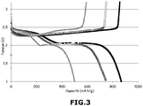
- the voltage (in volts, V) of the battery B-1 as a function of its specific capacity (in mAh / g) at a current regime of (C / 20, D / 20) and a temperature of 40 ° C is reported on the figure 3 for several cycles.
- the curve with the solid black squares represents the first cycle
- the curve with the empty black circles represents the second cycle
- the curve with the solid gray triangles represents the ninetieth cycle.
- the figure 3 shows no appearance of dendrites even after 90 cycles in battery B-1 according to the invention.
- Table 4 below presents the characteristics of the SA separator: the thickness e (in ⁇ m), the porosity P (in%), the porosity of the Gurley P Gurley type (in s / 100 cm 3 ), longitudinal thermal shrinkage measured at 100 ° C for 1 hour R L (in%), the transverse thermal shrinkage measured at 100 ° C for 1 hour R T (in%), the maximum resistance to perforation F max (in Newton N), and the elongation at break A (in mm). Unless otherwise indicated, these characteristics were obtained as described in Example 3 above.
- the positive electrode / SA separator / negative electrode assembly was then impregnated with a liquid electrolyte consisting of a 1.5 mol / l solution of LiTFSI in TEGDME.
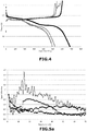
- the voltage (in volts, V) of the battery BA according to its specific capacity (in mAh / g) at a current regime of (C / 20, D / 20) and a temperature of 40 ° C is reported on the figure 4 for several cycles.
- the figure 4 shows the premature death of the BA battery at least in the ninth cycle induced by the formation of dendrites.
- the positive electrode / separator SB / negative electrode assembly was then impregnated with a liquid electrolyte consisting of a 1.5 mol / l solution of LiTFSI in TEGDME.
- Table 5 below shows the respective characteristics of separators S-2, S-3 and S-4 : the thickness e (in ⁇ m), the porosity P (in%), the porosity of type Gurley P Gurley (in s / 100 cm 3 ), the longitudinal thermal shrinkage measured at 100 ° C for 1 hour R L (in%), the transverse thermal shrinkage measured at 100 ° C for 1 hour R T (in%), the maximum resistance to the perforation F max (in Newton N), and elongation at break A (in mm). Unless otherwise indicated, these characteristics were obtained as described in Example 3 above.
- Each of the positive electrode / separator / negative electrode assemblies was then impregnated with a liquid electrolyte consisting of a 1.5 mol / l solution of LiTFSI in TEGDME.
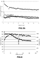
- the relative capacity corresponding to the ratio of the discharge capacity of the cycle n to the discharge capacity of the first cycle, the BA batteries (curve with open circles), B-1 (curve with solid squares), B-2 (curve with solid diamonds), B-3 (curve with empty squares) and B-4 (curve with solid squares) solid triangles) as a function of the number of cycles at a current regime of (C / 20, D / 20) and a temperature of 40 ° C is reported on the figure 5a .
- the figure 5a shows no appearance of dendrites even after 30 cycles in batteries according to the invention B-1, B-2, B-3 and B-4, regardless of the thickness of the biaxially oriented separator used. However, as observed in Comparative Example 4 above, the figure 5a shows the premature death of the BA battery not according to the invention, induced by the formation of dendrites.
- the density of energy density (ie density of capacity, considering the volume of positive electrode, separator and electrolyte) (in mAh / cm 3 ) of batteries BA (curve with the empty circles), B-1 ( curve with solid squares), B-2 (curve with solid diamonds), B-3 (curve with empty squares) and B-4 (curve with solid triangles) as a function of the number of cycles at a current regime (C / 20, D / 20) and a temperature of 40 ° C is reported on the figure 5b .
- the results of the figure 5b show the good cyclability of batteries according to the invention.
- the maximum density of energy density (117 mAh / cm 3 ) is obtained with the separator S-1 (considering the volume of positive electrode, separator and electrolyte).
- Lithium salt (LiTFSI) (28.2% by weight) was dissolved in TEGDME (21.8% by weight) with magnetic stirring at 50 ° C. Then, to the resulting mixture was added a Zeospan® POE copolymer (50% by weight). The resulting mixture was kneaded in the Plastograph® EC mixer as described in Example 2, at 80 ° C for 30 minutes. The electrolyte paste obtained was laminated at 95 ° C. between two silicone PET plastic films.
- the biaxially oriented polypropylene separator S-1 was previously impregnated with the gelled polymer electrolyte by co-rolling the separator and the gelled polymer electrolyte at 80 ° C. and at a pressure of 5 bars under a dry air atmosphere ( ie air with a dew point ⁇ -40 ° C).
- the specific capacity (in mAh / g) during the discharge as a function of the number of cycles (curve with the solid circles), as well as the coulombic efficiency (in%), corresponding to the ratio of the discharge capacity of the cycle n on the capacity cycle charge, as a function of the number of cycles (curve with solid squares) of the battery B-5 at a current regime of D / 20 and a temperature of 40 ° C, are reported on the figure 6 .
- the figure 6 shows no appearance of dendrites even after 85 cycles in the battery according to the invention B-5.
- the volume density of energy obtained is 83 mAh / cm 3 (considering the volume of positive electrode, separator and electrolyte).
- Lithium salt (LiTFSI) (17.7% by weight) was dissolved in TEGDME (27.3% by weight) with magnetic stirring at 50 ° C. Then, to the resulting mixture was added a copolymer of Zeospan® POE (15% by weight) and a copolymer of vinylidene fluoride and hexafluoropropylene (PVdF-co-HFP) (30% by weight). The resulting mixture was kneaded in the Plastograph® EC mixer as described in Example 2 at 130 ° C for 30 minutes. The electrolyte paste obtained was laminated at 125 ° C. between two silicone PET plastic films.
- the battery does not conform to the invention because it does not include a biaxially oriented porous separator comprising at least polypropylene.
- a biaxially oriented porous separator comprising at least polypropylene.
- the specific capacity (in mAh / g) during the discharge as a function of the number of cycles (curve with the solid circles), as well as the coulombic efficiency (in%), corresponding to the ratio of the discharge capacity of the cycle n on the capacity charge of the cycle n, as a function of the number of cycles (curve with solid squares) of the battery BC at a current regime of D / 40 and a temperature of 40 ° C, are reported on the figure 7 .
- the figure 8 shows the appearance of dendrites from the third cycle in the battery not in accordance with the invention BC, resulting in an impaired cyclability visible on the figure 7 .
- This premature dendritic growth can be attributed to the degradation of the PVdF-co-HFP by the polysulfides formed during the cycling, resulting in a deterioration of the mechanical properties of the gelled polymer electrolyte which then no longer plays its role anti-dendrite.
- the volume density of energy obtained is 95 mAh / cm 3 (considering the volume of positive electrode, separator and electrolyte).
Description
La présente invention se rapporte au domaine des batteries lithium soufre de hautes densités d'énergie et de puissance. En particulier, la présente invention concerne une batterie lithium soufre comprenant un séparateur poreux en polypropylène orienté biaxialement et son procédé de fabrication.The present invention relates to the field of lithium-sulfur batteries with high energy and power densities. In particular, the present invention relates to a lithium sulfur battery comprising a biaxially oriented polypropylene porous separator and its manufacturing process.
Les batteries au lithium sont devenues des constituants indispensables dans de nombreux dispositifs qui comprennent des appareils portables, tels que notamment les téléphones mobiles, les ordinateurs et l'outillage léger, ou des appareils plus lourds tels que des moyens de transports à deux roues (bicyclettes, cyclomoteurs) ou à quatre roues (véhicules automobiles électriques ou hybrides). Elles sont également largement étudiées pour une utilisation dans le domaine du stockage stationnaire d'énergie.Lithium batteries have become indispensable components in many devices that include portable devices, such as mobile phones, computers and light equipment, or heavier devices such as two-wheeled vehicles (bicycles). , mopeds) or four-wheeled vehicles (electric or hybrid motor vehicles). They are also widely studied for use in the field of stationary energy storage.
Une batterie au lithium métal comprend au moins une électrode négative et au moins une électrode positive entre lesquelles est placé un électrolyte solide ou un séparateur imprégné par un électrolyte liquide. L'électrode négative est constituée d'une feuille de lithium métallique ou d'alliage de lithium, éventuellement supportée par un collecteur de courant ; et l'électrode positive est constituée par un collecteur de courant supportant un matériau d'électrode contenant au moins une matière active d'électrode positive capable d'insérer des ions lithium de manière réversible, éventuellement un polymère qui joue le rôle de liant (e.g. poly(fluorure de vinylidène) ou PVdF) et/ou éventuellement un agent conférant une conductivité électronique (e.g. carbone). L'électrolyte liquide est par exemple constitué d'un sel de lithium en solution dans un solvant choisi pour optimiser le transport et la dissociation des ions. Le séparateur doit, quant à lui, assurer une parfaite isolation entre les deux électrodes pour éviter tout risque de court-circuit. Il est donc en matériau poreux non conducteur électronique, généralement en matériau polymère (e.g. polyéthylène) ou en fibres (e.g. fibres de verre ou fibres de bois), et doit avoir :
- une résistance mécanique appropriée, pour supporter les contraintes dues aux variations de volume des matières actives pendant les cycles de charge et de décharge,
- une résistance chimique suffisante pour assurer sa tenue dans le temps puisqu'il est immergé dans une solution très corrosive (i.e. électrolyte), et
- une structure poreuse appropriée, pour permettre la diffusion des anions et cations de l'électrolyte, et éviter tout transport de matière active d'une électrode sur l'autre.
- a suitable mechanical strength, to withstand the stresses due to volume variations of the active substances during the charging and discharging cycles,
- a sufficient chemical resistance to ensure its resistance over time since it is immersed in a very corrosive solution (ie electrolyte), and
- a suitable porous structure, to allow the diffusion of the anions and cations of the electrolyte, and to avoid any transport of active material from one electrode to the other.
Au cours du fonctionnement de la batterie, des ions lithium passent de l'une à l'autre des électrodes à travers l'électrolyte. Lors de la décharge de la batterie, une quantité de lithium réagit avec la matière active d'électrode positive à partir de l'électrolyte, et une quantité équivalente est introduite dans l'électrolyte à partir de la matière active de l'électrode négative, la concentration en lithium restant ainsi constante dans l'électrolyte. L'insertion du lithium dans l'électrode positive est compensée par apport d'électrons à partir de l'électrode négative via un circuit extérieur. Lors de la charge, les phénomènes inverses ont lieu.During the operation of the battery, lithium ions pass from one to the other of the electrodes through the electrolyte. During discharge of the battery, an amount of lithium reacts with the positive electrode active material from the electrolyte, and an equivalent amount is introduced into the electrolyte from the active material of the negative electrode, the lithium concentration thus remaining constant in the electrolyte. The insertion of the lithium into the positive electrode is compensated by supplying electrons from the negative electrode via an external circuit. During charging, the reverse phenomena take place.
Les divers constituants d'une batterie au lithium sont choisis de manière à produire, au coût le plus faible possible, des batteries qui ont une densité d'énergie élevée, une bonne stabilité au cyclage et qui fonctionnent avec sécurité.The various components of a lithium battery are chosen so as to produce, at the lowest possible cost, batteries which have a high energy density, good cycling stability and operate safely.
Un des systèmes de stockage électrochimique de l'énergie les plus prometteurs est la batterie lithium soufre, d'une part parce que le soufre élémentaire S8 est un élément abondant, économique et non toxique, et d'autre part parce que ce matériau présente une capacité spécifique et une densité massique d'énergie théoriques élevées, et respectivement de 1675 mAh/gsoufre et de 2600 Wh/kgsoufre, si le soufre élémentaire S8 est complètement réduit en sulfure de lithium Li2S à une tension proche de 2 volts (par rapport au couple Li+/Li0). Par comparaison, les densités massiques d'énergie obtenues actuellement pour les meilleures batteries Li-ion sont de 200-250 Wh/kg, de 100-150 Wh/kg pour une batterie Na-ion, et de 50 Wh/kg pour une batterie à flux rédox (bien connue sous l'anglicisme "redox-flow battery"). Il est donc possible d'espérer atteindre des densités d'énergie de l'ordre de 500 Wh/kg pour une batterie lithium soufre (i.e. Li/S), ce qui est comparable aux valeurs obtenues pour des batteries Li-air.One of the most promising electrochemical energy storage systems is the lithium sulfur battery, firstly because the elemental sulfur S 8 is an abundant, economic and non-toxic element, and secondly because this material presents a specific capacity and a high theoretical mass density of energy, and respectively of 1675 mAh / g sulfur and 2600 Wh / kg sulfur , if the elemental sulfur S 8 is completely reduced to lithium sulphide Li 2 S at a voltage close to 2 volts (relative to the Li + / Li 0 couple). By comparison, the mass densities of energy currently obtained for the best Li-ion batteries are 200-250 Wh / kg, 100-150 Wh / kg for a Na-ion battery, and 50 Wh / kg for a redox flow battery (well known as the "redox-flow battery "). It is therefore possible to achieve energy densities of the order of 500 Wh / kg for a lithium sulfur battery (ie Li / S), which is comparable to the values obtained for Li-air batteries.
Une batterie lithium soufre comprend généralement une électrode négative (i.e. anode) métallique composée de lithium ou d'un alliage à base de lithium, une électrode positive (i.e. cathode) comprenant du soufre ou un composé organique comprenant du soufre en tant que matière active, et un séparateur composé généralement d'une membrane poreuse de polyoléfines (e.g. polyéthylène, polypropylène) imprégnée par un électrolyte liquide comprenant au moins un sel de lithium, ou un électrolyte polymère assurant par lui-même à la fois la séparation physique des électrodes et le transport des ions lithium.A lithium sulfur battery generally comprises a negative electrode (ie anode) made of lithium metal or a lithium-based alloy, a positive electrode (ie cathode) comprising sulfur or an organic compound comprising sulfur as active ingredient, and a separator generally composed of a porous membrane of polyolefins (eg polyethylene, polypropylene) impregnated with a liquid electrolyte comprising at least one lithium salt, or a polymer electrolyte ensuring by itself both the physical separation of the electrodes and the transport of lithium ions.
Cependant, dans une batterie lithium soufre, plusieurs problèmes sont généralement rencontrés. Tout d'abord, au pôle négatif, l'électrode de lithium métal est sujette à l'apparition de dendrites à sa surface au cours de la recharge. En effet, le lithium ayant tendance à croître sous forme colonnaire, il se dépose de façon non uniforme à la surface de l'électrode en lithium métal et forme ainsi des dendrites. Au cours du cyclage, les dendrites croissent et peuvent venir perforer le séparateur placé entre les deux électrodes et provoquer un court-circuit. À l'issue d'un court-circuit local provoqué par une dendrite, celle-ci fait généralement office de fusible et s'autodétruit, ce qui entraîne peu de conséquences quant aux performances de la batterie. En revanche, la répétition de ces micros court-circuits contribue à une autodécharge de la batterie. Dans des cas extrêmes, le courant circulant à travers ces court-circuits pouvant être très important, cela induit un échauffement local et, si des conditions défavorables sont réunies, un possible emballement thermique de la batterie (e.g. diminution de la stabilité thermique de la batterie en raison du vieillissement, batterie portée à une température élevée liée à l'application). Ces dernières années, la recherche s'est préférentiellement orientée vers la mise au point d'électrolytes solides (e.g. électrolytes polymères gélifiés) destinée à remplacer les électrolytes liquides. En effet, l'utilisation d'électrolytes liquides entraîne quasi systématiquement l'apparition de court-circuits en cyclage ou lorsque les densités de courant appliquées sont élevées. De plus, les séparateurs conventionnels utilisés en présence d'un électrolyte liquide ne sont pas stables vis-à-vis du lithium métal et ont tendance à réagir avec ce dernier pour former une mousse, entraînant ainsi sa dégradation. Par ailleurs, au pôle positif, la réduction du soufre par le lithium conduit à la formation de polysulfures liquides chargés négativement et solubles dans la plupart des électrolytes liquides usuels, qui diffusent à travers le séparateur jusqu'à l'électrode négative où ils sont réduits. Cette réduction des polysulfures au pôle négatif conduit à la formation d'une couche de Li2S ou de Li2S2 sur le lithium métallique. Cette couche étant solide et isolante électrique, elle entraîne la passivation de l'électrode négative et le blocage des réactions électrochimiques. Les polysulfures intermédiaires de lithium Li2Sn (2 < n < 8) pouvant réagir avec l'électrode négative, ils favorisent également l'autodécharge. En outre, ils sont responsables de la mise en place d'un mécanisme navette qui se produit en charge et qui entraîne la dégradation des performances de la batterie, notamment en termes d'efficacité coulombique.However, in a lithium sulfur battery, several problems are generally encountered. First, at the negative pole, the lithium metal electrode is prone to the appearance of dendrites on its surface during charging. As lithium tends to grow in columnar form, it deposits unevenly on the surface of the lithium metal electrode and thus forms dendrites. During cycling, the dendrites grow and may perforate the separator placed between the two electrodes and cause a short circuit. At the end of a local short circuit caused by a dendrite, it usually acts as a fuse and self-destruct, which has little effect on the performance of the battery. On the other hand, the repetition of these microphones short-circuits contributes to a self-discharge of the battery. In extreme cases, the current flowing through these short circuits can be very important, it induces a local heating and, if adverse conditions are met, a possible thermal runaway battery (eg decreased thermal stability of the battery due to aging, battery raised to a high temperature related to the application). In recent years, research has focused on the development of solid electrolytes (eg gelled polymeric electrolytes) intended to replace liquid electrolytes. Indeed, the use of liquid electrolytes almost always leads to the occurrence of short circuits in cycling or when the current densities applied are high. In addition, conventional separators used in the presence of a liquid electrolyte are not stable to lithium metal and tend to react with the latter to form a foam, thus causing its degradation. Moreover, at the positive pole, the reduction of sulfur by lithium leads to the formation of negatively charged liquid polysulfides soluble in most of the usual liquid electrolytes, which diffuse through the separator to the negative electrode where they are reduced. . This reduction of the polysulfides at the negative pole leads to the formation of a Li 2 S or Li 2 S 2 layer on the lithium metal. This layer being solid and electrically insulating, it leads to the passivation of the negative electrode and the blocking of electrochemical reactions. The intermediate lithium polysulfides Li 2 S n (2 <n <8) can react with the negative electrode, they also promote self-discharge. In addition, they are responsible for the implementation of a shuttle mechanism that occurs in charge and which leads to degradation of battery performance, particularly in terms of coulombic efficiency.
Ainsi, Barchasz et al. ont décrit, dans la demande internationale
- au moins une électrode négative comprenant une feuille de lithium et un collecteur de courant en cuivre ;
- au moins une électrode positive comprenant une encre formée à partir de 75% en masse de soufre élémentaire S8 comme matière active, de 10% en masse de noir de carbone et de 5% en masse de fibres de carbone comme agents générant une conductivité électronique, et de 10% en masse de liant poly(fluorure de vinylidène) (PVdF), et un collecteur de courant en aluminium ;
- un séparateur d'électrodes comprenant au moins un non-tissé de fibres (e.g. fibres de verre, de polyéthylène téréphtalate (PET), de polyoléfines, de poly(vinyl alcool) (PVA), de polyamide (PA), etc...) et présentant une porosité d'au moins 50% et une épaisseur comprise entre 50 et 200 µm ; et
- un électrolyte en excès comprenant au moins un sel de lithium et imbibant ledit séparateur. De manière similaire, les documents
WO 2013/155038 A1 US 2004/009399 A1 WO 99/19931 A1 Journal of Power Sources, vol. 112, no. 2, 14 novembre 2002, pages 452-460
- at least one negative electrode comprising a lithium sheet and a copper current collector;
- at least one positive electrode comprising an ink formed from 75% by weight of elemental sulfur S 8 as active material, of 10% by weight of carbon black and 5% by weight of carbon fibers as agents generating electronic conductivity and 10% by weight polyvinylidene fluoride binder (PVdF), and an aluminum current collector;
- an electrode separator comprising at least one nonwoven of fibers (eg glass fibers, polyethylene terephthalate (PET), polyolefins, polyvinyl alcohol (PVA), polyamide (PA), etc.) and having a porosity of at least 50% and a thickness of between 50 and 200 μm; and
- an excess electrolyte comprising at least one lithium salt and imbibing said separator. Similarly, the documents
WO 2013/155038 A1 US 2004/009399 A1 WO 99/19931 A1 Journal of Power Sources, vol. 112, no. 2, November 14, 2002, pages 452-460
Selon Barchasz et al., l'utilisation d'un séparateur comprenant au moins un non-tissé de fibres et un excès d'électrolyte permet d'éviter la précipitation des espèces soufrées, ainsi que la passivation des électrodes, tout en obtenant une densité d'énergie massique importante de l'ordre de 200 Wh.kg-1. Toutefois, l'accumulateur lithium soufre obtenu n'est pas optimisé pour éviter la formation de dendrites et la diffusion de la matière active au travers de l'électrolyte (via le séparateur) afin d'obtenir une capacité de décharge stable sur plusieurs cycles. Par ailleurs, l'épaisseur des séparateurs testés (i.e. supérieure à 50 µm) ne permet pas de garantir une densité volumique d'énergie suffisante.According to Barchasz et al., The use of a separator comprising at least one nonwoven of fibers and an excess of electrolyte makes it possible to avoid the precipitation of the sulfur species, as well as the passivation of the electrodes, while obtaining a density significant mass energy of the order of 200 Wh.kg -1 . However, the lithium sulfur accumulator obtained is not optimized to prevent the formation of dendrites and the diffusion of the active material through the electrolyte ( via the separator) in order to obtain a stable discharge capacity over several cycles. Furthermore, the thickness of the separators tested (ie greater than 50 microns) does not ensure a density of sufficient energy density.
En parallèle, la demande de
Le but de la présente invention est de pallier les inconvénients de l'art antérieur précité et de mettre au point une batterie lithium soufre économique, aux performances électrochimiques améliorées, notamment en termes de stabilité au cyclage et de densité volumique d'énergie.The object of the present invention is to overcome the disadvantages of the aforementioned prior art and to develop an economical lithium sulfur battery with improved electrochemical performance, particularly in terms of cycling stability and volume density of energy.
Ce but est atteint par l'invention qui va être décrite ci-après.This object is achieved by the invention which will be described below.
L'invention a donc pour premier objet une batterie lithium soufre comprenant :
- une électrode négative comprenant du lithium métal ou un alliage de lithium métal,
- une électrode positive comprenant au moins un agent soufré choisi parmi le soufre élémentaire S8 et un composé organique soufré comprenant au moins une liaison S-S, au moins un liant polymère P1 et au moins un agent générant une conductivité électronique,
- un électrolyte comprenant au moins un polyéther linéaire ou cyclique liquide de faible masse molaire et au moins un sel de lithium L1, et
- un séparateur poreux,
- a negative electrode comprising lithium metal or a lithium metal alloy,
- a positive electrode comprising at least one sulfur-containing agent chosen from elemental sulfur S 8 and an organic sulfur compound comprising at least one SS bond, at least one polymeric binder P 1 and at least one agent generating an electronic conductivity,
- an electrolyte comprising at least one low molecular weight linear or cyclic liquid polyether and at least one lithium salt L 1 , and
- a porous separator,
La batterie de l'invention présente des performances électrochimiques remarquables en termes de densité volumique d'énergie et de stabilité de la capacité spécifique pendant la décharge sur un grand nombre de cycles, ce qui permet de penser que la diffusion des polysulfures est limitée.The battery of the invention exhibits outstanding electrochemical performance in terms of energy density density and specific capacity stability during discharge over a large number of cycles, suggesting that diffusion of the polysulfides is limited.
Dans la présente invention, « un polyéther linéaire ou cyclique liquide de faible masse molaire » signifie un polyéther linéaire ou cyclique liquide de masse molaire inférieure ou égale à 20 000 g·mol-1 environ, de préférence inférieure ou égale à 2000 g·mol-1 environ, et de préférence encore inférieure ou égale à 600 g·mol-1 environ.In the present invention, "linear or low molecular weight liquid cyclic polyether" means a linear or cyclic liquid polyether of molar mass less than or equal to approximately 20 000 g · mol -1 , preferably less than or equal to 2000 g · mol -1 approximately, and more preferably less than or equal to 600 g · mol -1 approximately.
Dans la présente invention, « un polyéther linéaire ou cyclique liquide de faible masse molaire » est également appelé « polyéther ».In the present invention, "linear or low molecular weight liquid cyclic polyether" is also referred to as "polyether".
Le séparateur orienté biaxialement utilisé dans la batterie lithium soufre de l'invention permet non seulement d'assurer la séparation électrique des électrodes, mais également d'éviter la formation de dendrites tout en garantissant de bonnes performances électrochimiques notamment en termes de stabilité en cyclage. En outre, le séparateur est stable vis-à-vis de l'électrolyte de la batterie, que ledit électrolyte soit sous forme liquide ou solide (e.g. électrolyte polymère gélifié). Enfin, grâce à la combinaison d'un séparateur orienté biaxialement et d'un électrolyte comprenant au moins un polyéther, le transport des ions lithium est optimisé tout en évitant la diffusion des polysulfures de l'électrode positive vers l'électrode négative.The biaxially oriented separator used in the lithium sulfur battery of the invention not only makes it possible to ensure the electrical separation of the electrodes, but also to avoid the formation of dendrites while guaranteeing good electrochemical performance, particularly in terms of stability in cycling. In addition, the separator is stable with respect to the electrolyte of the battery, whether said electrolyte is in liquid or solid form (e.g. gelled polymer electrolyte). Finally, thanks to the combination of a biaxially oriented separator and an electrolyte comprising at least one polyether, the lithium ion transport is optimized while avoiding the diffusion of polysulfides from the positive electrode to the negative electrode.
Dans un mode de réalisation particulier de l'invention, le séparateur présente une épaisseur allant de 5 µm à 50 µm environ, de préférence de 10 µm à 40 µm environ, et de préférence encore de 10 µm à 30 µm environ.In a particular embodiment of the invention, the separator has a thickness ranging from about 5 μm to about 50 μm, preferably from about 10 μm to about 40 μm, and more preferably from about 10 μm to about 30 μm.
En effet, le séparateur ne doit pas être trop fin, afin de présenter une bonne tenue mécanique et électrochimique pendant le cyclage, d'éviter les court-circuits, et d'accueillir une quantité d'électrolyte suffisante. Cependant, il ne doit pas être trop épais, sous peine de pénaliser la batterie en termes de densités d'énergie massique et volumique (effet de masse), et en termes de performances à haut régime ou à basse température (effet de polarisation).Indeed, the separator must not be too thin, to have good mechanical and electrochemical resistance during cycling, to avoid short circuits, and to accommodate a sufficient amount of electrolyte. However, it must not be too thick, as it may penalize the battery in terms of mass and volume energy densities (mass effect), and in terms of high-speed or low-temperature performance (polarization effect).
Selon une forme de réalisation préférée de l'invention, le séparateur présente une porosité supérieure ou égale à 50% en volume environ, de préférence supérieure ou égale à 55% en volume environ, et de préférence encore supérieure ou égale à 60% en volume environ.According to a preferred embodiment of the invention, the separator has a porosity greater than or equal to about 50% by volume, preferably greater than or equal to about 55% by volume, and more preferably greater than or equal to 60% by volume. about.
Dans un mode de réalisation particulier, le séparateur présente des pores de taille moyenne allant de 50 nm à 3 µm environ, de préférence de 50 nm à 1 µm environ, et de préférence encore de 100 nm à 500 nm environ.In a particular embodiment, the separator has pores of average size ranging from about 50 nm to about 3 μm, preferably from about 50 nm to about 1 μm, and more preferably from about 100 nm to about 500 nm.
Grâce à cette porosité, ledit séparateur peut être imprégné facilement par l'électrolyte tout en garantissant une tenue mécanique suffisante.Thanks to this porosity, said separator can be easily impregnated by the electrolyte while ensuring sufficient mechanical strength.
En effet, le séparateur de l'invention présente une résistance à la perforation (bien connue sous l'anglicisme « puncture strength ») d'au moins 30 Newton environ, et de préférence d'au moins 40 Newton environ.Indeed, the separator of the invention has a resistance to perforation (well known by the Anglicism " puncture strength ") of at least about 30 Newton, and preferably at least about 40 Newton.
En outre, le séparateur de l'invention présente un allongement à la rupture d'au moins 5 mm environ, et de préférence d'au moins 10 mm environ. Cet allongement est mesuré lors de tests de perforation à l'aide d'un poinçon métallique, à température ambiante.In addition, the separator of the invention has an elongation at break of at least about 5 mm, and preferably at least about 10 mm. This elongation is measured during perforation tests using a metal punch, at room temperature.
Le séparateur peut présenter une porosité de type Gurley allant de 50 à 500 s/100 cm3 environ, et de préférence allant de 50 à 400 s/100 cm3 environ. La porosité de type Gurley PGurley indique le temps mis (en seconde) pour que 100 cm3 d'air traversent 1 pouce-carré de séparateur. La porosité de type Gurley PGurley traduit la perméabilité d'un séparateur : plus la valeur PGurley est faible, plus les échanges à travers celui-ci sont favorisés et ainsi, plus la diffusion des espèces est facilitée.The separator may have a Gurley porosity ranging from about 50 to about 500 sec / 100 cm 3 , and preferably from about 50 to about 400 sec / 100 cm 3 . Gurley P Gurley porosity indicates the time taken (in seconds) for 100 cm 3 of air to pass through 1 inch-square of separator. The Gurley P Gurley type porosity reflects the permeability of a separator: the lower the Gurley P value, the more favorable the exchanges through it, and thus the easier the diffusion of the species.
Le séparateur peut présenter un retrait thermique dans le sens longitudinal (i.e. retrait longitudinal) et/ou un retrait thermique dans le sens transversal (i.e. retrait transversal) strictement inférieur à 15% environ, et de préférence strictement inférieur à 10% environ, quelle que soit son épaisseur (le retrait est mesuré à 100°C pendant 1 heure).The separator may have a thermal shrinkage in the longitudinal direction (ie longitudinal shrinkage) and / or a thermal shrinkage in the transverse direction (ie transverse shrinkage) strictly less than about 15%, and preferably less than about 10%, whatever its thickness (the shrinkage is measured at 100 ° C. for 1 hour).
En effet, le séparateur poreux orienté biaxialement doit avoir un retrait thermique suffisamment bas pour pouvoir supporter des montées en température dans la batterie lithium soufre et ainsi, éviter que la batterie soit dégradée par un échauffement non maîtrisé. Sa mise en oeuvre dans le procédé de fabrication des cellules est par ailleurs facilitée.Indeed, the biaxially oriented porous separator must have a sufficiently low thermal shrinkage to be able to withstand temperature rises in the lithium sulfur battery and thus prevent the battery from being degraded by uncontrolled heating. Its implementation in the cell manufacturing process is also facilitated.
Dans la présente invention, l'expression « orienté biaxialement » signifie que le séparateur a été obtenu par étirage dans une direction longitudinale (« machine direction ») et dans une direction transversale à la direction longitudinale.In the present invention, the term "biaxially oriented" means that the separator has been obtained by stretching in a longitudinal direction (" machine direction ") and in a direction transverse to the longitudinal direction.
Le séparateur peut comprendre en outre un matériau polymère choisi parmi le polyéthylène, un copolymère du polyéthylène et un de leurs mélanges.The separator may further comprise a polymeric material selected from polyethylene, a copolymer of polyethylene and a mixture thereof.
Le polypropylène peut être un homopolymère du polypropylène (PP) ou un copolymère du polypropylène.The polypropylene may be a homopolymer of polypropylene (PP) or a copolymer of polypropylene.
Lorsque le séparateur comprend d'autres matériaux polymères que du polypropylène, il comprend au moins 90% en masse de polypropylène, et de préférence au moins 95% en masse de polypropylène, par rapport à la masse totale du séparateur.When the separator comprises other polymeric materials than polypropylene, it comprises at least 90% by weight of polypropylene, and preferably at least 95% by weight of polypropylene, relative to the total mass of the separator.
Le séparateur de l'invention peut être uniquement constitué de polypropylène.The separator of the invention may consist solely of polypropylene.
Le séparateur ne contient de préférence aucune charge inorganique et/ou aucune céramique.The separator preferably contains no inorganic filler and / or no ceramic.
Le séparateur ne comprend pas, de préférence, de matériau(x) polymère(s) qui peu(ven)t réagir avec les polysulfures, tels que le PVdF ou les polymères comprenant au moins une double liaison C=C tels que les caoutchoucs synthétiques naturels.The separator preferably does not comprise polymeric material (s) which can be reacted with polysulfides, such as PVdF or polymers comprising at least one C doubleC double bond, such as synthetic rubbers. natural.
Le séparateur peut être monocouche ou multicouche. Lorsqu'il est multicouche, il est de préférence bicouche de façon à présenter une épaisseur la plus faible possible sans toutefois nuire à ses propriétés mécaniques.The separator may be monolayer or multilayer. When it is multilayer, it is preferably bilayer so as to have a thickness as small as possible without however affecting its mechanical properties.
Le séparateur doit posséder de bonnes propriétés de mouillabilité à l'égard de l'électrolyte utilisé de façon à ce que son imprégnation soit facile, notamment par simple mise en contact lorsque l'électrolyte est liquide, ou par co-laminage lorsque l'électrolyte est solide ou gélifié.The separator must have good wettability properties with respect to the electrolyte used so that its impregnation is easy, in particular by simple contacting when the electrolyte is liquid, or by co-rolling when the electrolyte is solid or gelled.
Le polyéther de l'électrolyte de la batterie de l'invention peut être choisi parmi :
- * les polyéthylènes glycols de formule H-[O-CH2-CH2]m-OH dans laquelle m est compris entre 1 et 13,
- * les éthers de glycol de formule R-[O-CH2-CH2]p-O-R' dans laquelle p est compris entre 1 et 13 et R et R', identiques ou différents, sont des groupes alkyles linéaires, ramifiés ou cycliques, pouvant comprendre de 1 à 20 atomes de carbone,
- * les éthers de formule R1-[CH2-O]q-R1' dans laquelle q est compris entre 1 et 13, R1 et R1', identiques ou différents, sont des alkyles linéaires, ramifiés ou cycliques, pouvant comprendre de 1 à 20 atomes de carbone et éventuellement des hétéroatomes,
- * les éthers cycliques pouvant comprendre de 2 à 20 atomes de carbone, les polyéthers cycliques pouvant comprendre de 3 à 40 atomes de carbone, et
- * un de leurs mélanges.
- polyethylene glycols of formula H- [O-CH 2 -CH 2 ] m -OH in which m is between 1 and 13,
- the glycol ethers of formula R- [O-CH 2 -CH 2 ] p -OR 'in which p is between 1 and 13 and R and R', which are identical or different, are groups linear, branched or cyclic alkyls, which can comprise from 1 to 20 carbon atoms,
- the ethers of formula R 1 - [CH 2 -O] q -R 1 ' in which q is between 1 and 13, R 1 and R 1' , which are identical or different, are linear, branched or cyclic alkyls, comprise from 1 to 20 carbon atoms and optionally heteroatoms,
- cyclic ethers which may comprise from 2 to 20 carbon atoms, the cyclic polyethers may comprise from 3 to 40 carbon atoms, and
- * one of their mixtures.
Le(s) polyéther(s) utilisé(s) dans l'électrolyte de l'invention est (sont) particulièrement stable(s) vis-à-vis du lithium et des composés soufrés, permettant ainsi de limiter au maximum les réactions parasites.The polyether (s) used in the electrolyte of the invention is (are) particularly stable with respect to lithium and sulfur compounds, thus making it possible to limit as much as possible the parasitic reactions .
Le polyéther de l'invention est de préférence linéaire.The polyether of the invention is preferably linear.
Dans un mode de réalisation encore plus préféré, le polyéther est le tétra éthylène glycol diméthyléther (TEGDME) de formule CH3O-(CH2-CH2)4-OCH3 (i.e. R, R' = CH3 et p = 4).In an even more preferred embodiment, the polyether is tetraethylene glycol dimethyl ether (TEGDME) of formula CH 3 O- (CH 2 -CH 2 ) 4 -OCH 3 (ie R, R '= CH 3 and p = 4 ).
Le sel de lithium L1 peut être choisi parmi le fluorate de lithium (LiFO3), le bis(trifluorométhanesulfonyl) imide de lithium (LiTFSI), l'hexafluorophosphate de lithium (LiPF6), le fluoroborate de lithium (LiBF4), le métaborate de lithium (LiBO2), le perchlorate de lithium (LiClO4), le nitrate de lithium (LiNO3), le lithium bis(fluorosulfonyl)imide (LiFSI) et leurs mélanges.The lithium salt L 1 may be chosen from lithium fluoride (LiFO 3 ), lithium bis (trifluoromethanesulfonyl) imide (LiTFSI), lithium hexafluorophosphate (LiPF 6 ), lithium fluoroborate (LiBF 4 ), lithium metaborate (LiBO 2 ), lithium perchlorate (LiClO 4 ), lithium nitrate (LiNO 3 ), lithium bis (fluorosulfonyl) imide (LiFSI) and mixtures thereof.
LiTFSI est le sel de lithium L1 préféré.LiTFSI is the preferred lithium salt L 1 .
Il va de soi que l'électrolyte de la batterie de l'invention est non-aqueux, c'est-à-dire qu'il ne comprend donc pas d'eau ou de solvants aqueux. En effet, un électrolyte aqueux n'est pas compatible avec une électrode négative en lithium métal.It goes without saying that the electrolyte of the battery of the invention is non-aqueous, that is to say that it does not include water or aqueous solvents. Indeed, an aqueous electrolyte is not compatible with a negative electrode lithium metal.
L'électrolyte ne comprend pas, de préférence, de solvants organiques de type carbonate, ces derniers pouvant réagir avec les polysulfures formés pendant le cyclage.The electrolyte does not preferably comprise organic solvents of carbonate type, the latter being able to react with the polysulfides formed during the cycling.
Selon une première variante, l'électrolyte est un électrolyte liquide. Il imbibe alors complètement le séparateur afin d'en imprégner la porosité.According to a first variant, the electrolyte is a liquid electrolyte. It soaks the separator completely in order to impregnate the porosity.
Selon cette première variante, la concentration du sel de lithium L1 dans l'électrolyte liquide va de 0,8 à 8 mol/l environ, et de préférence de 1 à 5 mol/l environ.According to this first variant, the concentration of the lithium salt L 1 in the liquid electrolyte is from 0.8 to 8 mol / l, and preferably from 1 to 5 mol / l approximately.
L'électrolyte liquide peut être uniquement constitué d'un sel de lithium L1 et d'un polyéther.The liquid electrolyte may consist solely of a lithium salt L 1 and a polyether.
L'électrolyte liquide est, de préférence, une solution comprenant 1,5 mol/l de LiTFSI dans du TEGDME.The liquid electrolyte is preferably a solution comprising 1.5 mol / l LiTFSI in TEGDME.
Selon une deuxième variante, l'électrolyte est un électrolyte polymère gélifié, il est alors déposé sur le séparateur afin d'en imprégner la porosité et de former un film d'électrolyte sec autoporté.According to a second variant, the electrolyte is a gelled polymer electrolyte, it is then deposited on the separator in order to impregnate the porosity and form a self-supporting dry electrolyte film.
Selon cette deuxième variante, l'électrolyte comprend en outre au moins un liant polymère P2.According to this second variant, the electrolyte further comprises at least one polymeric binder P 2 .
Le liant polymère P2 peut être choisi parmi les polyoléfines telles que les homopolymères ou les copolymères d'éthylène et de propylène, ou un mélange d'au moins deux de ces polymères ; les homopolymères et les copolymères d'oxyde d'éthylène (e.g. POE, copolymère du POE), d'oxyde de méthylène, d'oxyde de propylène, d'épichlorhydrine ou d'allylglycidyléther, ou leurs mélanges ; les polymères halogénés tels que les homopolymères et les copolymères de chlorure de vinyle, de fluorure de vinylidène (PVdF), de chlorure de vinylidène, de tétrafluorure d'éthylène, ou de chlorotrifluoroéthylène, les copolymères de fluorure de vinylidène et de hexafluoropropylène (PVdF-co-HFP) ou leurs mélanges ; les polymères non conducteurs électroniques de type anionique tels que le poly(styrène sulfonate), le poly(acide acrylique), le poly(glutamate), l'alginate, la pectine, ou leurs mélanges ; les polyacrylates ; et un de leurs mélanges.The polymer binder P 2 may be chosen from polyolefins such as homopolymers or copolymers of ethylene and propylene, or a mixture of at least two of these polymers; homopolymers and copolymers of ethylene oxide (eg POE, POE copolymer), methylene oxide, propylene oxide, epichlorohydrin or allylglycidyl ether, or mixtures thereof; halogenated polymers such as homopolymers and copolymers of vinyl chloride, vinylidene fluoride (PVdF), vinylidene chloride, ethylene tetrafluoride, or chlorotrifluoroethylene, copolymers of vinylidene fluoride and hexafluoropropylene (PVdF). co-HFP) or mixtures thereof; anionic-type non-conductive electronic polymers such as poly (styrene sulfonate), poly (acrylic acid), poly (glutamate), alginate, pectin, or mixtures thereof; polyacrylates; and one of their mixtures.
L'électrolyte polymère gélifié peut comprendre de 20 à 70% en masse environ de liant polymère P2, et de préférence de 40 à 60% en masse environ de liant polymère P2, par rapport à la masse totale de l'électrolyte polymère gélifié.The gelled polymer electrolyte may comprise from 20 to 70% by weight of polymer binder P 2 , and preferably from 40 to 60% by weight of polymer binder P 2 , relative to the total weight of the gelled polymer electrolyte. .
Les liants polymères P2 préférés sont le copolymère d'oxyde d'éthylène et d'oxyde de propylène et le copolymère d'oxyde d'éthylène et d'oxyde de butylène.The preferred polymeric binders P 2 are the copolymer of ethylene oxide and propylene oxide and the copolymer of ethylene oxide and butylene oxide.
L'électrolyte polymère gélifié peut comprendre de 15 à 45% en masse environ de sel de lithium L1, et de préférence de 20 à 35% en masse environ de sel de lithium L1 par rapport à la masse totale de l'électrolyte polymère gélifié.The gelled polymer electrolyte may comprise from 15 to 45% by weight of lithium salt L 1 , and preferably from 20 to 35% by weight of lithium salt L 1 relative to the total mass of the polymer electrolyte. gelled.
L'électrolyte polymère gélifié peut comprendre de 5 à 40% en masse environ de polyéther, et de préférence de 10 à 30% en masse environ de polyéther, par rapport à la masse totale de l'électrolyte polymère gélifié.The gelled polymer electrolyte may comprise from about 5 to about 40% by weight of polyether, and preferably from about 10 to about 30% by weight of polyether, based on the total weight of the gelled polymer electrolyte.
La batterie conforme à l'invention peut fonctionner entre 0 et 110°C environ, et de préférence entre 20 et 100°C environ.The battery according to the invention can operate between 0 and 110 ° C, and preferably between 20 and 100 ° C.
Dans un mode de réalisation particulier de l'invention, l'électrode positive de la batterie de l'invention comprend au moins 45% en masse environ de soufre (S), et de préférence au moins 50% en masse environ de soufre (S) par rapport à la masse totale de ladite électrode positive.In a particular embodiment of the invention, the positive electrode of the battery of the invention comprises at least about 45% by weight of sulfur (S), and preferably at least about 50% by weight of sulfur (S). ) with respect to the total mass of said positive electrode.
Le composé organique soufré peut être choisi parmi les polysulfures organiques, notamment ceux de formule générale R2-S-Sn-R3 dans laquelle R2 et R3, identiques ou différents, représentent une chaîne alkyle linéaire, ramifiée ou cyclique, pouvant comprendre de 1 à 20 atomes de carbone, et n étant compris entre 1 et 50 ; et les polymères disulfures présentant un enchaînement de liaisons S-S pouvant être cassées lors du cycle de décharge d'une batterie lithium soufre, et reformées lors du cycle de charge.The sulfur-containing organic compound may be chosen from organic polysulfides, especially those of the general formula R 2 -SS n -R 3 in which R 2 and R 3 , which may be identical or different, represent a linear, branched or cyclic alkyl chain, which may comprise From 1 to 20 carbon atoms, and n being from 1 to 50; and disulfide polymers having a sequence of SS bonds that can be broken during the discharge cycle of a lithium sulfur battery, and reformed during the charge cycle.
L'agent soufré est de préférence le soufre élémentaire S8. Ce dernier confère en effet à la batterie lithium soufre une densité d'énergie plus importante, de par sa grande capacité massique de stockage.The sulfur-containing agent is preferably elemental sulfur S 8 . The latter confers indeed the lithium sulfur battery a higher energy density, by its high mass storage capacity.
L'agent générant une conductivité électronique peut représenter de 5 à 30% en masse environ, de préférence de 5 à 20% environ en masse, par rapport à la masse totale de l'électrode positive.The agent generating an electronic conductivity may represent from 5 to 30% by weight, preferably from 5 to 20% by weight, relative to the total mass of the positive electrode.
L'agent générant une conductivité électronique convenant pour la présente invention est de préférence choisi parmi le noir de carbone, le carbone SP, le noir d'acétylène, les fibres et nanofibres de carbone, les nanotubes de carbone, le graphène, le graphite, les particules et fibres métalliques et l'un de leurs mélanges.The agent generating an electronic conductivity that is suitable for the present invention is preferably chosen from carbon black, SP carbon, acetylene black, carbon fibers and nanofibers, carbon nanotubes, graphene, graphite, metal particles and fibers and one of their mixtures.
L'agent générant une conductivité électronique est de préférence le noir de carbone.The agent generating an electronic conductivity is preferably carbon black.
Selon une forme de réalisation préférée de l'invention, l'agent générant une conductivité électronique est un agent carboné essentiellement mésoporeux présentant les caractéristiques suivantes :
- une surface spécifique SBET supérieure ou égale à 800 m2/g environ, de préférence supérieure ou égale à 1000 m2/g environ, et encore plus préférentiellement supérieure ou égale à 1400 m2/g environ, ladite surface spécifique étant calculée par la méthode B.E.T (i.e. méthode de Brunauer, Emmett et Teller, 1938),
- une taille moyenne des mésopores comprise
entre 4 et 10 nm environ, ladite taille étant calculée par la méthode B.J.H (i.e. méthode de Barrett, Joyner et Halenda, 1951), et - un volume poreux total supérieur ou égal à 1,5 cm3/g environ, de préférence supérieur ou égal à 2 cm3/g environ, et encore plus préférentiellement supérieur ou égal à 2,5 cm3/g environ, ledit volume poreux total étant calculé par la méthode B.E.T.
- a specific surface area S BET greater than or equal to 800 m 2 / g, preferably greater than or equal to 1000 m 2 / g, and still more preferably greater than or equal to 1400 m 2 / g, said specific surface being calculated by the BET method (ie Brunauer's method, Emmett and Teller, 1938),
- an average size of the mesopores of between about 4 and 10 nm, said size being calculated by the BJH method (ie method of Barrett, Joyner and Halenda, 1951), and
- a total pore volume greater than or equal to 1.5 cm 3 / g, preferably greater than or equal to 2 cm 3 / g, and still more preferably greater than or equal to 2.5 cm 3 / g, said pore volume total being calculated by the BET method
Dans la présente invention, l'expression " agent carboné " signifie un agent comprenant essentiellement du carbone, c'est-à-dire comprenant au moins 80% en masse environ de carbone, de préférence au moins 90% en masse environ de carbone, et de préférence encore au moins 95% en masse environ de carbone.In the present invention, the expression "carbonaceous agent" means an agent essentially comprising carbon, that is to say comprising at least about 80% by weight of carbon, preferably at least about 90% by weight of carbon, and more preferably at least about 95% by weight of carbon.
Dans la présente invention, l'expression « agent carboné essentiellement mésoporeux » signifie que l'agent carboné comprend un volume mésoporeux représentant au moins 70% en volume environ du volume poreux total, de préférence au moins 80% en volume environ du volume poreux total, et de préférence encore au moins 90% en volume environ du volume poreux total, ledit volume mésoporeux étant calculé à partir de la méthode B.J.H.In the present invention, the term "essentially mesoporous carbonaceous agent" means that the carbonaceous agent comprises a mesoporous volume of at least about 70% by volume of the total pore volume, preferably at least about 80% by volume of the total pore volume, and more preferably at least about 90% by volume of the total pore volume, said mesoporous volume being calculated from the BJH method
Dans la description qui va suivre et sauf mention contraire explicite, toutes les valeurs de surface spécifique indiquées ont été calculées par la méthode B.E.T. De la même façon, toutes les valeurs de taille de mésopores indiquées ont été calculées par la méthode B.J.H. Enfin, toutes les valeurs de volume poreux total indiquées ont été déterminées par la méthode B.E.T et toutes les valeurs de volume mésoporeux ont été calculées par la méthode B.J.H.In the description which follows and unless explicitly stated otherwise, all the specific surface area values indicated were calculated by the B.E.T. method. Similarly, all indicated mesopore size values were calculated by B.J.H. Finally, all the total pore volume values indicated were determined by the B.E.T method and all the mesoporous volume values were calculated by the B.J.H. method.
De préférence, les particules d'agent carboné sont sous forme de particules sphériques (i.e. sous forme de billes) afin de favoriser la conduction notamment dans le sens perpendiculaire à l'électrode positive (i.e. dans le sens de son épaisseur) et ainsi de faciliter les échanges électrochimiques entre l'électrode positive et l'électrode négative. En effet, les particules d'agent carboné sous forme de particules sphériques ont une propension à former des réseaux conducteurs tridimensionnels. Lorsque les particules d'agent carboné sont sous forme de particules sphériques, cela signifie que plusieurs atomes de carbone forment des sphères.Preferably, the carbonaceous particles are in the form of spherical particles (ie in the form of beads) in order to promote the conduction, in particular in the direction perpendicular to the positive electrode (ie in the direction of its thickness) and thus to facilitate electrochemical exchanges between the positive electrode and the negative electrode. In fact, the carbonaceous particles in the form of spherical particles have a propensity to form three-dimensional conductive networks. When the carbonaceous particles are in the form of spherical particles, this means that several carbon atoms form spheres.
Ainsi, afin de favoriser la conduction dans le sens transversal de l'électrode positive (i.e. dans le sens de son épaisseur), l'agent carboné n'est de préférence pas sous forme de fibres ou de plaquettes telles que des fibres de carbone ou des plaquettes de graphène, puisque celles-ci vont s'orienter préférentiellement dans le sens de fabrication du film.Thus, in order to promote conduction in the transverse direction of the positive electrode (ie in the direction of its thickness), the carbonaceous agent is preferably not in the form of fibers or platelets such as carbon fibers or graphene platelets, since these will move preferentially in the direction of manufacture of the film.
Dans un mode de réalisation particulièrement préféré de l'invention, l'agent carboné comprend des particules de carbone sphériques ayant un diamètre moyen allant de 20 nm à 100 nm environ. Ainsi, chaque sphère comprenant plusieurs atomes de carbone présente un diamètre moyen allant de 20 nm à 100 nm environ.In a particularly preferred embodiment of the invention, the carbonaceous agent comprises spherical carbon particles having a mean diameter ranging from about 20 nm to about 100 nm. Thus, each sphere comprising a plurality of carbon atoms has a mean diameter ranging from about 20 nm to about 100 nm.
Ledit agent carboné est de préférence le noir de carbone.Said carbonaceous agent is preferably carbon black.
À titre d'exemple de noir de carbone essentiellement mésoporeux présentant les caractéristiques telles que définies dans la présente invention, on peut citer les noirs de carbone commercialisés sous les références : Ketjenblack 600JD®, Ketjenblack 700JD® et Timcal Ensaco 350G®.As an example of essentially mesoporous carbon black presenting the characteristics as defined in the present invention, mention may be made of the carbon blacks marketed under the references: Ketjenblack 600JD®, Ketjenblack 700JD® and Timcal Ensaco 350G®.
Selon une forme de réalisation particulière, l'électrode positive comprend de 5 à 20% en masse environ de liant polymère P1, et de préférence de 5 à 15% en masse environ de liant polymère P1, par rapport à la masse totale de l'électrode positive.According to a particular embodiment, the positive electrode comprises from 5 to 20% by weight of polymer binder P 1 , and preferably from 5 to 15% by weight of polymer binder P 1 , relative to the total mass of the positive electrode.
Le liant polymère P1 peut être choisi parmi les copolymères d'éthylène et de propylène, ou un mélange d'au moins deux de ces polymères ; les homopolymères et les copolymères d'oxyde d'éthylène (e.g. POE, copolymère du POE), d'oxyde de méthylène, d'oxyde de propylène, d'épichlorhydrine ou d'allylglycidyléther, ou leurs mélanges ; les polymères halogénés tels que les homopolymères et les copolymères de chlorure de vinyle, de fluorure de vinylidène (PVdF), de chlorure de vinylidène, de tétrafluorure d'éthylène, ou de chlorotrifluoroéthylène, les copolymères de fluorure de vinylidène et de hexafluoropropylène (PVdF-co-HFP) ou leurs mélanges ; les polyacrylates tels que le polyméthacrylate de méthyle ; les polyalcools tels que l'alcool polyvinylique (PVA), les polymères conducteurs électroniques tels que la polyaniline, le polypyrrole, les polyfluorènes, les polypyrènes, les polyazulènes, les polynaphtalènes, les polyacétylènes, le poly(p-phénylène-vinylène), les polycarbazoles, les polyindoles, les polyazépines, les polythiophènes, le polysulfure de p-phénylène ou leurs mélanges ; les polymères de type cationique tels que le polyéthylèneimine (PEI), la polyaniline sous forme de sel éméraldine (ES), le poly(N-vinylimidazole quaternisé), le Poly(acrylamide-co-chlorure de diallyldiméthyl ammonium) (AMAC) ou leurs mélanges ; et un de leurs mélanges.The polymer binder P 1 may be chosen from copolymers of ethylene and propylene, or a mixture of at least two of these polymers; homopolymers and copolymers of ethylene oxide (eg POE, POE copolymer), methylene oxide, propylene oxide, epichlorohydrin or allylglycidyl ether, or mixtures thereof; halogenated polymers such as homopolymers and copolymers of vinyl chloride, vinylidene fluoride (PVdF), vinylidene chloride, ethylene tetrafluoride, or chlorotrifluoroethylene, copolymers of vinylidene fluoride and hexafluoropropylene (PVdF). co-HFP) or mixtures thereof; polyacrylates such as polymethyl methacrylate; polyalcohols such as polyvinyl alcohol (PVA), electronically conductive polymers such as polyaniline, polypyrrole, polyfluorenes, polypyrenes, polyazulenes, polynaphthalenes, polyacetylenes, poly (p-phenylenevinylene), polycarbazoles, polyindoles, polyazepines, polythiophenes, p-phenylene polysulfide or mixtures thereof; cationic type polymers such as polyethyleneimine (PEI), polyaniline in the form of emeraldine salt (ES), poly (N-vinylimidazole quaternized), poly (acrylamide-co-diallyldimethyl ammonium chloride) (AMAC) or their mixtures; and one of their mixtures.
Un polymère de type cationique (i.e. chargé positivement) permet d'améliorer la rétention des polysulfures qui sont chargés négativement dans l'électrode positive, et ainsi de limiter la diffusion des polysulfures dans l'électrolyte lors du cyclage.A polymer of cationic type (ie positively charged) makes it possible to improve the retention of the polysulfides which are negatively charged in the positive electrode, and thus to limit the diffusion of the polysulphides in the electrolyte during the cycling.
Le liant polymère P1 est de préférence le PVA, le PEI, l'AMAC ou un de leurs mélanges.The polymeric binder P 1 is preferably PVA, PEI, AMAC or a mixture thereof.
L'électrode positive peut comprendre en outre au moins un polyéther linéaire ou cyclique liquide de faible masse molaire tel que défini dans la présente invention.The positive electrode may further comprise at least one linear or low molecular weight liquid cyclic polyether as defined in the present invention.
L'électrode positive peut comprendre de 2 à 30% en masse environ de polyéther, et de préférence de 5 à 25% en masse environ de polyéther, par rapport à la masse totale de l'électrode positive.The positive electrode may comprise from about 2 to about 30 weight percent polyether, and preferably about 5 to about 25 weight percent polyether, based on the total weight of the positive electrode.
L'électrode positive peut comprendre en outre au moins un sel de lithium L2.The positive electrode may further comprise at least one lithium salt L 2 .
L'électrode positive peut comprendre de 2 à 25% en masse environ de sel de lithium L2, de préférence de 3 à 15% en masse environ de sel de lithium L2, et de préférence encore de 3 à 8% en masse environ de sel de lithium L2, par rapport à la masse totale de l'électrode positive.The positive electrode may comprise from 2 to 25% by weight of lithium salt L 2 , preferably from 3 to 15% by weight of lithium salt L 2 , and more preferably from 3 to 8% by weight approximately. lithium salt L 2, relative to the total mass of the positive electrode.
Le sel de lithium L2 peut être choisi parmi le fluorate de lithium (LiFO3), le bis(trifluorométhanesulfonyl) imide de lithium (LiTFSI), l'hexafluorophosphate de lithium (LiPF6), le fluoroborate de lithium (LiBF4), le métaborate de lithium (LiBO2), le perchlorate de lithium (LiClO4), le nitrate de lithium (LiNO3), le lithium bis(fluorosulfonyl)imide (LiFSI), et leurs mélanges.The lithium salt L 2 may be chosen from lithium fluoride (LiFO 3 ), lithium bis (trifluoromethanesulfonyl) imide (LiTFSI), lithium hexafluorophosphate (LiPF 6 ), lithium fluoroborate (LiBF 4 ), lithium metaborate (LiBO 2 ), lithium perchlorate (LiClO 4 ), lithium nitrate (LiNO 3 ), lithium bis (fluorosulfonyl) imide (LiFSI), and mixtures thereof.
LiTFSI est le sel de lithium L2 préféré.LiTFSI is the preferred lithium salt L 2 .
L'électrode positive de l'invention peut présenter une porosité inférieure ou égale à 40% en volume environ, et de préférence inférieure ou égale à 30% en volume environ, par rapport au volume total de l'électrode. Cela permet ainsi d'améliorer la densité d'énergie de la batterie.The positive electrode of the invention may have a porosity less than or equal to about 40% by volume, and preferably less than or equal to about 30% by volume, relative to the total volume of the electrode. This makes it possible to improve the energy density of the battery.
Il convient de noter que la masse totale de l'électrode positive comprend la masse de l'agent soufré, la masse du liant polymère P1, la masse de l'agent carboné générant une conductivité électronique, éventuellement la masse du polyéther s'il est présent et éventuellement la masse du sel de lithium L2 s'il est présent.It should be noted that the total mass of the positive electrode comprises the mass of the sulfur-containing agent, the mass of the polymer binder P 1 , the mass of the carbonaceous agent generating an electronic conductivity, possibly the mass of the polyether if is present and possibly the mass of lithium salt L 2 if it is present.
L'électrode positive peut être préparée :
- a) en mélangeant au moins un agent soufré avec au moins un agent conférant une conductivité électronique, au moins un liant polymère P1, éventuellement au moins un sel de lithium L2, éventuellement au moins un polyéther linéaire ou cyclique liquide de faible masse molaire, et éventuellement au moins un solvant dudit liant polymère P1, pour obtenir une pâte d'électrode,
- b) en appliquant ladite pâte d'électrode sur au moins un support,
- c) en séchant ladite pâte d'électrode pour obtenir une électrode positive sous forme de film supporté.
- a) by mixing at least one sulfur-containing agent with at least one agent giving an electronic conductivity, at least one polymeric binder P 1 , optionally at least one lithium salt L 2 , optionally at least one liquid linear or cyclic polyether of low molar mass , and optionally at least one solvent of said polymeric binder P 1 , to obtain an electrode paste,
- b) applying said electrode paste to at least one support,
- c) drying said electrode paste to obtain a positive electrode in the form of a supported film.
Le liant polymère P1, le sel de lithium L2 et le polyéther linéaire ou cyclique liquide de faible masse molaire sont tels que définis ci-dessus.The polymer binder P 1 , the lithium salt L 2 and the linear or cyclic low molecular weight polyether or polyether are as defined above.
L'étape a) peut être réalisée par extrusion ou par broyage.Step a) may be carried out by extrusion or grinding.
L'extrusion est très avantageuse puisqu'elle permet d'obtenir facilement des électrodes peu poreuses tout en utilisant peu de solvant. Elle permet également d'éviter une étape de calandrage sur l'électrode sèche qui peut engendrer des modifications de structure de l'électrode, nuire au bon enrobage des grains de l'agent carboné et ainsi peut induire un effondrement de l'électrode au cours du cyclage. Enfin, l'étape de calandrage présente l'inconvénient d'augmenter le nombre d'étapes pour obtenir l'électrode et ainsi son coût de production.Extrusion is very advantageous since it makes it possible to easily obtain low-porous electrodes while using little solvent. It also makes it possible to avoid a calendering step on the dry electrode which may cause changes in the structure of the electrode, adversely affect the good coating of the grains of the carbonaceous agent and thus may induce a collapse of the electrode during cycling. Finally, the calendering step has the disadvantage of increasing the number of steps to obtain the electrode and thus its cost of production.
Le solvant du liant polymère P1 de l'étape a) permet de solubiliser ledit liant polymère P1.The solvent of the polymeric binder P 1 of step a) makes it possible to solubilize said polymeric binder P 1 .
Lorsqu'il est présent, ledit solvant représente de préférence moins de 30% en masse environ de la masse totale du mélange d'agent soufré, d'agent générant une conductivité électronique, de liant polymère P1, éventuellement de sel de lithium L1 et éventuellement de polyéther.When present, said solvent preferably represents less than about 30% by weight of the total weight of the mixture of sulfur-containing agent, agent generating an electronic conductivity, polymer binder P 1 , optionally lithium salt L 1 and optionally polyether.
L'utilisation lors de la fabrication de l'électrode positive d'une faible quantité de solvant du liant polymère P1 permet de conduire à une électrode positive de faible porosité (i.e. ≤ 40% en volume environ). Cette faible porosité permet de contrôler et d'optimiser la quantité de soufre présente dans l'électrode positive, et ainsi de parvenir à des densités volumiques d'énergie optimales.The use during manufacture of the positive electrode of a small amount of solvent of the polymer binder P 1 makes it possible to lead to a positive electrode of low porosity (ie ≤ 40% by volume approximately). This weak porosity makes it possible to control and optimize the amount of sulfur present in the positive electrode, and thus to achieve optimal energy density densities.
Le solvant de l'étape a) peut être choisi parmi l'eau, la N-méthylpyrrolidone, les solvants de type carbonate tels que le carbonate d'éthylène, le carbonate de propylène, le carbonate de diméthyle, le carbonate de diéthyle ou le carbonate de méthyle et d'éthyle, l'acétone, les alcools tels que le méthanol, l'éthanol ou le propanol, et leurs mélanges.The solvent of step a) may be selected from water, N- methylpyrrolidone, carbonate type solvents such as ethylene carbonate, propylene carbonate, dimethyl carbonate, diethyl carbonate or the like. methyl and ethyl carbonate, acetone, alcohols such as methanol, ethanol or propanol, and mixtures thereof.
Le solvant est de préférence choisi parmi l'eau, l'acétone, les alcools, et leurs mélanges.The solvent is preferably selected from water, acetone, alcohols, and mixtures thereof.
L'étape b) peut être réalisée par laminage ou par enduction.Step b) can be carried out by rolling or coating.
Le support peut être un collecteur de courant et/ou un film de support.The support may be a current collector and / or a support film.
À titre d'exemple de collecteur de courant, on peut citer un collecteur de courant en aluminium recouvert d'une couche à base de carbone (couche anticorrosion).As an example of a current collector, there may be mentioned an aluminum current collector covered with a carbon-based layer (anticorrosive layer).
À titre d'exemple de film de support, on peut citer un film plastique de type polyéthylène téréphtalate (PET) siliconé.As an example of a support film, there may be mentioned a plastic film of the polyethylene terephthalate (PET) silicone type.
Le film supporté d'électrode positive obtenu à l'issue de l'étape c) peut avoir une épaisseur allant de 2 à 100 µm environ, et de préférence de 10 à 60 µm.The supported positive electrode film obtained at the end of step c) may have a thickness ranging from about 2 to 100 μm, and preferably from 10 to 60 μm.
L'étape c) peut être réalisée à une température suffisante pour permettre d'éliminer le solvant de l'étape a).Step c) can be performed at a temperature sufficient to allow removal of the solvent from step a).
Le soufre et les composés organiques comprenant du soufre présentent le désavantage d'être électriquement et ioniquement isolants (e.g. conductivité électronique du soufre S8 = 5 x 10-30 S.cm-1 à 25°C). Par conséquent, afin de permettre une réaction électrochimique réversible à des régimes de courant élevés, le soufre doit donc être de préférence en contact intime avec un additif électriquement conducteur tel que le carbone.Sulfur and organic compounds comprising sulfur have the disadvantage of being electrically and ionically insulating (eg electronic conductivity of sulfur S 8 = 5 × 10 -30 S.cm -1 at 25 ° C). Therefore, in order to allow a reversible electrochemical reaction at high current regimes, the sulfur must therefore preferably be in intimate contact with an electrically conductive additive such as carbon.
Ainsi, lorsque l'agent conférant une conductivité électronique est un agent carboné essentiellement mésoporeux tel que défini dans la présente invention, ledit agent carboné essentiellement mésoporeux peut subir, en présence de l'agent soufré, un prétraitement pour former un matériau composite comprenant du soufre (S) et du carbone (C) afin de favoriser ledit contact intime.Thus, when the electronic conductivity conferring agent is an essentially mesoporous carbonaceous agent as defined herein. According to the invention, said essentially mesoporous carbonaceous agent can undergo, in the presence of the sulfur-containing agent, pretreatment to form a composite material comprising sulfur (S) and carbon (C) in order to promote said intimate contact.
Ledit prétraitement peut comprendre les étapes suivantes :
- i) une étape de mélange d'un agent carboné essentiellement mésoporeux tel que défini dans la présente invention et d'un agent soufré tel que défini dans la présente invention, la quantité de soufre (S) dans ledit mélange allant de 75% à 85% en masse environ,
- ii) une étape de broyage du mélange obtenu à l'étape précédente i),
- iii) une étape de traitement thermique du mélange broyé obtenu à l'étape précédente ii) dans un récipient fermé, à une température suffisante pour faire fondre le soufre, et
- iv) une étape de broyage du mélange traité thermiquement de l'étape précédente iii), afin d'obtenir un matériau composite comprenant du soufre (S) et du carbone (C).
- i) a step of mixing an essentially mesoporous carbonaceous agent as defined in the present invention and a sulfur-containing agent as defined in the present invention, the amount of sulfur (S) in said mixture ranging from 75% to 85%; % by mass approximately,
- ii) a step of grinding the mixture obtained in the preceding step i),
- iii) a heat treatment step of the ground mixture obtained in the preceding step ii) in a closed vessel, at a temperature sufficient to melt the sulfur, and
- iv) a grinding step of the heat-treated mixture of the preceding step iii), in order to obtain a composite material comprising sulfur (S) and carbon (C).
Selon une forme de réalisation préférée, la quantité de soufre (S) dans le mélange de l'étape i) va de 80% à 85% en masse environ.According to a preferred embodiment, the amount of sulfur (S) in the mixture of step i) ranges from about 80% to about 85% by weight.
L'étape ii) de broyage permet de faciliter la répartition homogène du soufre sur le carbone. Elle peut être effectuée manuellement, notamment à l'aide d'un mortier, ou mécaniquement, notamment à l'aide d'un broyeur à billes.Step ii) grinding facilitates the homogeneous distribution of sulfur on the carbon. It can be carried out manually, in particular by means of a mortar, or mechanically, in particular by means of a ball mill.
La température suffisante de l'étape iii) est avantageusement choisie de telle sorte que le soufre soit à l'état liquide et que la viscosité du soufre fondu soit faible.The sufficient temperature of step iii) is advantageously chosen so that the sulfur is in the liquid state and the viscosity of the molten sulfur is low.
La température suffisante du traitement thermique de l'étape iii) peut aller de 115°C à 270°C environ, de préférence de 130°C à 220°C environ, et de préférence encore de 140°C à 170°C environ.The sufficient temperature of the heat treatment of step iii) may range from about 115 ° C to about 270 ° C, preferably from about 130 ° C to about 220 ° C, and more preferably from about 140 ° C to about 170 ° C.
La durée du traitement thermique de l'étape iii) peut aller de 30 minutes à 24 heures environ, et de préférence de 1 à 5 heures environ.The duration of the heat treatment of step iii) can range from about 30 minutes to 24 hours, and preferably from 1 to about 5 hours.
L'étape iii) est de préférence effectuée sous atmosphère d'air sec, notamment présentant un point de rosée inférieur ou égal à -30°C environ.Step iii) is preferably carried out under a dry air atmosphere, in particular having a dew point less than or equal to -30 ° C.
Les inventeurs de la présente demande ont ainsi découvert que lorsque l'agent carboné présente une taille de mésopores particulière allant de 4 à 10 nm, le soufre est capable, lors de l'étape iii), de remplir la porosité de l'agent carboné. En effet, la taille des pores de l'agent carboné doit être suffisamment élevée (c'est-à-dire supérieure à 4 nm) pour permettre au soufre fondu de pénétrer à l'intérieur des pores, mais suffisamment faible (c'est-à-dire inférieure à 10 nm) pour exercer une rétention suffisante des polysulfures lors du cyclage.The inventors of the present application have thus discovered that when the carbonaceous agent has a particular mesopore size ranging from 4 to 10 nm, the sulfur is capable, during step iii), of filling the porosity of the carbonaceous agent. . Indeed, the pore size of the carbonaceous agent must be sufficiently high (that is to say greater than 4 nm) to allow the molten sulfur to penetrate inside the pores, but sufficiently low (this is less than 10 nm) to exert sufficient retention of polysulfides during cycling.
De plus, la surface spécifique élevée (SBET ≥ 700 m2/g) de l'agent carboné permet d'obtenir une fine couche de soufre sur tout le squelette formé par l'agent carboné et d'éviter la formation d'agglomérats de soufre dans le matériau composite de l'invention et de ce fait, la diffusion rapide du soufre lors du cyclage. Le volume poreux important est également nécessaire pour retenir efficacement les polysulfures formés au cours du cyclage.In addition, the high specific surface area (S BET ≥ 700 m 2 / g) of the carbonaceous agent makes it possible to obtain a thin layer of sulfur over the entire skeleton formed by the carbonaceous agent and to avoid the formation of agglomerates. of sulfur in the composite material of the invention and thereby the rapid diffusion of sulfur during cycling. The large pore volume is also necessary to effectively retain polysulfides formed during cycling.
Enfin, le matériau composite tel qu'obtenu à l'issue de l'étape iv) présente un revêtement fin de soufre réparti de façon homogène, permettant ainsi d'augmenter son accessibilité lors des réactions électrochimiques et sa stabilité mécanique.Finally, the composite material as obtained at the end of step iv) has a thin coating of sulfur homogeneously distributed, thereby increasing its accessibility during electrochemical reactions and its mechanical stability.
L'étape iv) peut être effectuée manuellement, notamment à l'aide d'un mortier, ou mécaniquement, notamment à l'aide d'un broyeur à billes.Step iv) can be carried out manually, in particular using a mortar, or mechanically, in particular using a ball mill.
Ainsi, à l'issue de l'étape iv), le matériau composite comprenant du soufre et du carbone est structuré de telle sorte que le soufre forme un revêtement de surface de l'agent carboné en entrant dans les mésopores de celui-ci.Thus, at the end of step iv), the composite material comprising sulfur and carbon is structured such that the sulfur forms a surface coating of the carbonaceous agent by entering the mesopores thereof.
Le prétraitement peut comprendre en outre, entre l'étape iii) et l'étape iv), une étape de refroidissement du récipient fermé comprenant le mélange broyé.The pretreatment may further comprise, between step iii) and step iv), a cooling step of the closed container comprising the ground mixture.
Selon une forme de réalisation préférée, le prétraitement ne comprend pas d'autre(s) étape(s) de traitement thermique que l'étape iii).According to a preferred embodiment, the pretreatment does not include any other heat treatment step (s) than step iii).
Le prétraitement permettant de conduire au matériau composite est simple, rapide et ne nécessite pas de dispositif complexe. Grâce à ce prétraitement, l'enrobage de l'agent carboné par le soufre est facilité avec un faible coût de production.The pretreatment making it possible to lead to the composite material is simple, fast and does not require a complex device. With this pretreatment, the coating of the carbonaceous agent with sulfur is facilitated with a low production cost.
Lorsque le mélange d'agent soufré et d'agent carboné essentiellement mésoporeux subit le prétraitement tel que défini dans la présente invention, l'étape a) de préparation de l'électrode positive consiste à mélanger ledit matériau composite comprenant du soufre (S) et du carbone (C) et tel que défini ci-dessus, avec au moins un liant polymère P1, éventuellement au moins un sel de lithium L1, éventuellement au moins un polyéther linéaire ou cyclique liquide de faible masse molaire, et éventuellement au moins un solvant dudit liant polymère P1, pour obtenir une pâte d'électrode.When the mixture of sulfur agent and essentially mesoporous carbonaceous agent undergoes the pretreatment as defined in the present invention, step a) of preparing the positive electrode consists of mixing said composite material comprising sulfur (S) and carbon (C) and as defined above, with at least one polymeric binder P 1 , optionally at least one lithium salt L 1 , optionally at least one liquid linear or cyclic low molecular weight polyether, and optionally at least a solvent of said polymer binder P 1 , to obtain an electrode paste.
Dans un mode de réalisation particulier, l'électrode positive de l'invention ne comprend pas d'agent conférant une conductivité électronique autre que le noir de carbone essentiellement mésoporeux tel que défini dans la présente invention.In a particular embodiment, the positive electrode of the invention does not include an agent conferring electronic conductivity other than the substantially mesoporous carbon black as defined in the present invention.
En effet, la présence du noir de carbone essentiellement mésoporeux peut suffire à conférer à l'électrode positive une conductivité électronique suffisante pour permettre un bon fonctionnement de la batterie.Indeed, the presence of essentially mesoporous carbon black can suffice to give the positive electrode sufficient electronic conductivity to allow proper operation of the battery.
L'invention a pour deuxième objet un procédé de fabrication d'une batterie lithium soufre telle que définie dans le premier objet de l'invention, caractérisé en ce qu'il comprend les étapes suivantes :
- A) une étape de préparation d'un électrolyte liquide ou d'un électrolyte polymère gélifié tel que défini dans la présente invention, notamment par mélange d'au moins un polyéther linéaire ou cyclique liquide de faible masse molaire avec au moins un sel de lithium L1,
- B) une étape d'assemblage d'une électrode positive, d'une électrode négative et d'un séparateur tels que définis dans la présente invention,
- C-1) une étape d'imprégnation de l'assemblage tel qu'obtenu à l'étape B) par l'électrolyte liquide préparé à l'étape A), ou
- C-2) une étape d'imprégnation du séparateur par l'électrolyte polymère gélifié préparé à l'étape A), ladite imprégnation étant préalable à l'étape B) d'assemblage.
- A) a step of preparing a liquid electrolyte or a gelled polymer electrolyte as defined in the present invention, in particular by mixing at least one linear or low molecular weight liquid cyclic polyether with at least one lithium salt L 1 ,
- B) a step of assembling a positive electrode, a negative electrode and a separator as defined in the present invention,
- C-1) a step of impregnating the assembly as obtained in step B) by the liquid electrolyte prepared in step A), or
- C-2) a step of impregnating the separator with the gelled polymer electrolyte prepared in step A), said impregnation being prior to the assembly step B).
Le polyéther linéaire ou cyclique liquide de faible masse molaire, le sel de lithium L1 et le liant polymère P2 sont tels que définis dans le premier objet de l'invention.The low molecular weight linear or cyclic liquid polyether, the lithium salt L 1 and the polymeric binder P 2 are as defined in the first subject of the invention.
L'électrolyte liquide de l'étape A) est de préférence préparé en dissolvant sous agitation au moins un sel de lithium L1 dans un polyéther linéaire ou cyclique liquide de faible masse molaire, éventuellement à une température allant de 20 à 120°C environ.The liquid electrolyte of step A) is preferably prepared by dissolving with stirring at least one lithium salt L 1 in a low molecular weight linear or cyclic liquid polyether, optionally at a temperature ranging from 20 to 120 ° C. .
L'électrolyte polymère gélifié de l'étape A) peut être obtenu par extrusion d'au moins un liant polymère P2 avec une solution comprenant au moins un polyéther linéaire ou cyclique liquide de faible masse molaire et au moins un sel de lithium L1 pour obtenir une pâte d'électrolyte, puis par laminage de la pâte d'électrolyte, notamment entre deux films de support pour obtenir un film d'électrolyte polymère gélifié.The gelled polymer electrolyte of step A) may be obtained by extrusion of at least one polymeric binder P 2 with a solution comprising at least one low molecular weight linear or cyclic liquid polyether and at least one lithium salt L 1 to obtain an electrolyte paste, then by rolling the electrolyte paste, in particular between two support films to obtain a gelled polymer electrolyte film.
L'extrusion peut être réalisée à une température allant de 60 à 170°C environ.The extrusion can be carried out at a temperature ranging from 60 to 170 ° C.
La concentration du sel de lithium L1 dans ladite solution peut aller de 2 à 25 mol/l environ.The concentration of lithium salt L 1 in said solution may range from about 2 to 25 mol / l.
Les deux films de support peuvent être des films plastiques de PET siliconés.The two support films may be silicone PET plastic films.
L'imprégnation du séparateur par l'électrolyte polymère gélifié (cf. étape C-2)) peut être effectuée par co-laminage du séparateur et du film d'électrolyte polymère gélifié, notamment à une température de 80°C environ, et de préférence à une pression de 5 bars environ.The impregnation of the separator with the gelled polymer electrolyte (see step C-2)) can be carried out by co-rolling the separator and the gelled polymer electrolyte film, in particular at a temperature of about 80 ° C., and preferably at a pressure of about 5 bar.
Les étapes A) et C-2) peuvent être une seule et même étape au cours de laquelle la pâte d'électrolyte obtenue par extrusion est laminée directement sur le séparateur pour obtenir un séparateur imprégné d'un électrolyte polymère gélifié.Steps A) and C-2) can be a single step during which the electrolyte paste obtained by extrusion is laminated directly. on the separator to obtain a separator impregnated with a gelled polymer electrolyte.
La présente invention est illustrée par les exemples ci-après, auxquels elle n'est cependant pas limitée.The present invention is illustrated by the following examples, to which it is however not limited.
Les matières premières utilisées dans les exemples sont listées ci-après :
- noir de carbone « Ketjenblack 600JD® », AkzoNobel,
- soufre S8, de pureté 99,5%, Sigma Aldrich,
- copolymère du POE, « ZSN 8100 », Zeospan,
- copolymère de fluorure de vinylidène et de hexafluoropropylène (PVdF-co-HFP), « Solex », Solvay,
- LiTFSI, 3M,
- Film de PET siliconé, Mitsubishi,
- TEGDME de pureté 98%, Alfa Aesar,
- alcool polyvinylique (PVA) de masse molaire 72 000 g/mol, BioChemica,
- séparateur monocouche en polypropylène S-A, Celgard 2500,
- séparateur monocouche orienté biaxialement en polypropylène S-1, BPF220, Bolloré,
- séparateur bicouche orienté biaxialement en polypropylène S-2, Treopore PBS M63-NV509/09, Treofan,
- séparateur monocouche orienté biaxialement en polypropylène S-3, Treopore PDA M10-NV549/08, Treofan,
- séparateur monocouche orienté biaxialement en polypropylène S-4, Treopore PDA M4-NV549/09, Treofan.
- carbon black "Ketjenblack 600JD®", AkzoNobel,
- sulfur S 8 , 99.5% purity, Sigma Aldrich,
- copolymer of POE, "ZSN 8100", Zeospan,
- copolymer of vinylidene fluoride and hexafluoropropylene (PVdF-co-HFP), "Solex", Solvay,
- LiTFSI, 3M,
- Silicone PET film, Mitsubishi,
- TEGDME of purity 98%, Alfa Aesar,
- polyvinyl alcohol (PVA) with a molecular weight of 72,000 g / mol, BioChemica,
- single layer polypropylene separator SA, Celgard 2500,
- biaxially oriented monolayer separator made of polypropylene S-1, BPF220, Bolloré,
- biaxially oriented bilayer separator made of S-2 polypropylene , Treopore PBS M63-NV509 / 09, Treofan,
- biaxially oriented polypropylene monolayer separator S-3, Treopore PDA M10-NV549 / 08, Treofan,
- Biaxially oriented monolayer separator in S-4 polypropylene , Treopore PDA M4-NV549 / 09, Treofan.
Sauf indications contraires, tous les matériaux ont été utilisés tels que reçus des fabricants.Unless otherwise indicated, all materials have been used as received from manufacturers.
Un mélange carbone/soufre a été préparé en mélangeant un noir de carbone Ketjenblack avec du soufre S8 dans les proportions massiques suivantes C/S : 18,8/81,2.A carbon / sulfur mixture was prepared by mixing a Ketjenblack carbon black with sulfur S 8 in the following mass proportions C / S: 18.8 / 81.2.
Le mélange C/S ainsi obtenu a ensuite été broyé au mortier puis entreposé dans un récipient fermé.The C / S mixture thus obtained was then ground in a mortar and stored in a closed container.
Ledit récipient contenant le mélange broyé de carbone et de soufre a été soumis à un traitement thermique à une température de 155°C pendant 1h30 sous air sec.Said container containing the crushed mixture of carbon and sulfur was subjected to a heat treatment at a temperature of 155 ° C for 1h30 in dry air.
Le mélange traité thermiquement a ensuite été broyé au mortier pour obtenir le matériau composite 1. The heat-treated mixture was then grinded to obtain the
Le tableau 1 ci-dessous présente les caractéristiques [surface spécifique (en m2/g), volume poreux total (en cm3/g), volume poreux (en cm3/g), diamètre moyen des pores (en nm)] du noir de carbone utilisé pour préparer le matériau composite 1 :
La surface spécifique, le volume total poreux, le volume poreux B.J.H, le diamètre moyen des pores du noir de carbone Ketjenblack ont été évalués à l'aide d'un appareil vendu sous la dénomination commerciale ASAP2010, par la société Microméritics.The specific surface area, the total pore volume, the pore volume BJH, the average pore diameter of the Ketjenblack carbon black were evaluated using an apparatus sold under the trade name ASAP2010 by Micromeritics.
La
L'analyse par microscopie électronique à balayage (MEB) a été effectuée à l'aide d'un appareil vendu sous la dénomination commerciale JSM-7600F, par la société Jeol.The scanning electron microscopy (SEM) analysis was carried out using an apparatus sold under the trade name JSM-7600F by the company Jeol.
La
À titre comparatif, la
Le matériau composite 1 obtenu dans l'exemple 1 a été mélangé à 80°C pendant 30 minutes avec du tétraéthylène glycol diméthyl éther (TEGDME), de l'alcool polyvinylique (PVA), un sel de lithium (LiTFSI) et de l'eau dans un mélangeur vendu sous la dénomination commerciale Plastograph® EC par la société Brabender®. La quantité d'eau utilisée représentait 20% en masse environ de la masse totale du matériau composite, du TEGDME, du PVA et du sel de lithium LiTFSI.The
La pâte ainsi obtenue a ensuite été laminée à 95°C sur un collecteur de courant en aluminium recouvert d'une couche à base de carbone.The resulting slurry was then rolled at 95 ° C onto an aluminum current collector coated with a carbon-based layer.
Le film ainsi obtenu a été séché à 80°C pendant 20 minutes dans une étuve pour obtenir une électrode positive E-1 sous forme de film conforme à l'invention.The film thus obtained was dried at 80 ° C. for 20 minutes in an oven to obtain a positive electrode E-1 in the form of a film in accordance with the invention.
Le tableau 2 ci-dessous présente la composition massique de l'électrode positive E-1 obtenue :
Une batterie B-1 a été préparée en assemblant sous atmosphère anhydre (air avec un point de rosée < -40°C) par laminage manuel à température ambiante :
- l'électrode positive E-1 obtenue dans l'exemple 2,
- un séparateur S-1 BPF220 (Bolloré) en polypropylène orienté biaxialement, et
- une électrode négative comprenant du lithium métal sous forme d'un film de lithium métal de 100µm d'épaisseur environ.
- the positive electrode E-1 obtained in example 2,
- a biaxially oriented polypropylene separator S-1 BPF220 (Bolloré), and
- a negative electrode comprising lithium metal in the form of a lithium metal film approximately 100 μm thick.
Le tableau 3 ci-dessous présente les caractéristiques du séparateur S-1 : l'épaisseur e (en µm), la porosité P (en %), la porosité de type Gurley PGurley (en s/100 cm3), le retrait thermique longitudinal mesuré à 100°C pendant 1 heure RL (en %), le retrait thermique transversal mesuré à 100°C pendant 1 heure RT (en %), la résistance maximale à la perforation Fmax (en Newton N), et l'allongement à la rupture A (en mm).Table 3 below shows the characteristics of the S-1 separator : the thickness e (in μm), the porosity P (in%), the porosity of Gurley P Gurley type (in s / 100 cm 3 ), the shrinkage. thermal longitudinal measured at 100 ° C for 1 hour R L (in%), the transverse thermal shrinkage measured at 100 ° C for 1 hour R T (in%), the maximum resistance to perforation F max (in Newton N), and elongation at break A (in mm).
La porosité de type Gurley PGurley est mesurée à l'aide d'un densimètre automatique vendu sous la dénomination commerciale Guenine Gurley Modèle 4340.Gurley P Gurley porosity is measured using an automatic densimeter sold under the trade name Guenine Gurley Model 4340.
La porosité P est calculée en comparant l'épaisseur réelle du séparateur et son épaisseur théorique estimée à partir de sa masse et de la densité du polypropylène.The porosity P is calculated by comparing the actual thickness of the separator and its theoretical thickness estimated from its mass and the density of the polypropylene.
Les retraits thermiques longitudinal RL et transversal RT ont été estimés selon la norme ISO11501 (données obtenues auprès des fournisseurs de séparateurs).Longitudinal thermal withdrawals R L and transverse thermal losses R T have been estimated according to ISO11501 (data obtained from separator suppliers).
La résistance à la perforation maximale Fmax et l'allongement à la rupture A ont été obtenus à l'aide de tests de perforation ASTM D3420 réalisés à température ambiante à l'aide d'un dynamomètre vendu sous la dénomination commerciale Adamel-Lhomargy de type DY32.
L'ensemble électrode positive/séparateur S-1/électrode négative a alors été imprégné par un électrolyte liquide constitué d'une solution à 1,5 mol/l de LiTFSI dans du TEGDME.The positive electrode / S-1 separator / negative electrode assembly was then impregnated with a liquid electrolyte consisting of a 1.5 mol / l solution of LiTFSI in TEGDME.
La tension (en volts, V) de la batterie B-1 en fonction de sa capacité spécifique (en mAh/g) à un régime de courant de (C/20, D/20) et une température de 40°C est reportée sur la
La
Ces résultats montrent que l'utilisation d'un séparateur en polypropylène orienté biaxialement dans une batterie lithium soufre permet d'éviter la formation de dendrites, tout en conservant une densité d'énergie volumique importante supérieure à 120 mAh/cm3 (en considérant le volume d'électrode positive, de séparateur et d'électrolyte).These results show that the use of a biaxially oriented polypropylene separator in a lithium sulfur battery makes it possible to avoid the formation of dendrites, while maintaining a high density of energy density greater than 120 mAh / cm 3 (considering the positive electrode, separator and electrolyte volume).
Une batterie B-A a été préparée en assemblant sous atmosphère anhydre (air avec un point de rosée < -40°C) par laminage manuel à température ambiante :
- l'électrode positive E-1 obtenue dans l'exemple 2,
- un séparateur S-A en polypropylène non orienté biaxialement, et
- une électrode négative comprenant du lithium métal sous forme d'un film de lithium métal de 100 µm d'épaisseur environ.
- the positive electrode E-1 obtained in example 2,
- a biaxially oriented non-oriented polypropylene separator SA , and
- a negative electrode comprising lithium metal in the form of a lithium metal film approximately 100 μm thick.
Le tableau 4 ci-dessous présente les caractéristiques du séparateur S-A : l'épaisseur e (en µm), la porosité P (en %), la porosité de type Gurley PGurley (en s/100 cm3), le retrait thermique longitudinal mesuré à 100°C pendant 1 heure RL (en %), le retrait thermique transversal mesuré à 100°C pendant 1 heure RT (en %), la résistance maximale à la perforation Fmax (en Newton N), et l'allongement à la rupture A (en mm). Sauf indication(s) contraire(s), ces caractéristiques ont été obtenues comme décrit dans l'exemple 3 ci-dessus.
L'ensemble électrode positive/séparateur S-A/électrode négative a alors été imprégné par un électrolyte liquide constitué d'une solution à 1,5 mol/l de LiTFSI dans du TEGDME.The positive electrode / SA separator / negative electrode assembly was then impregnated with a liquid electrolyte consisting of a 1.5 mol / l solution of LiTFSI in TEGDME.
La tension (en volts, V) de la batterie B-A en fonction de sa capacité spécifique (en mAh/g) à un régime de courant de (C/20, D/20) et une température de 40°C est reportée sur la
Sur cette
La
Ces résultats montrent que l'utilisation d'un séparateur en polypropylène qui n'est pas orienté biaxialement dans une batterie lithium soufre ne permet pas d'éviter la formation de dendrites et altère les performances électrochimiques de la batterie lithium soufre.These results show that the use of a polypropylene separator which is not biaxially oriented in a lithium sulfur battery does not prevent the formation of dendrites and alters the electrochemical performance of the lithium sulfur battery.
Une batterie B-B a été préparée en assemblant sous atmosphère anhydre (air avec un point de rosée < -40°C) par laminage à 5 bars et à 80°C :
- l'électrode positive E-1 obtenue dans l'exemple 2,
- un séparateur S-B comprenant deux séparateurs S-A en polypropylène non orientés biaxialement et accolés par simple juxtaposition, et
- une électrode négative comprenant du lithium métal sous forme d'un film de lithium métal de 100 µm d'épaisseur environ.
- the positive electrode E-1 obtained in example 2,
- a separator SB comprising two polypropylene SA separators not oriented biaxially and joined by simple juxtaposition, and
- a negative electrode comprising lithium metal in the form of a lithium metal film approximately 100 μm thick.
L'ensemble électrode positive/séparateur S-B/électrode négative a alors été imprégné par un électrolyte liquide constitué d'une solution à 1,5 mol/l de LiTFSI dans du TEGDME.The positive electrode / separator SB / negative electrode assembly was then impregnated with a liquid electrolyte consisting of a 1.5 mol / l solution of LiTFSI in TEGDME.
L'utilisation de deux séparateurs non orientés biaxialement et accolés permet d'éviter la croissance prématurée des dendrites. Cependant, l'augmentation de l'épaisseur totale du séparateur (2 x 25 µm = 50 µm) engendre une diminution de la densité volumique d'énergie de 82 mAh/cm3 (lorsque le séparateur S-A est utilisé) à environ 50 mAh/cm3 (lorsque le séparateur S-B est utilisé) (en considérant le volume d'électrode positive, de séparateur et d'électrolyte).The use of two non-biaxially and contiguous separators avoids the premature growth of dendrites. However, the increase in the total thickness of the separator (2 × 25 μm = 50 μm) results in a decrease in the energy density of 82 mAh / cm 3 (when the separator SA is used) at about 50 mAh / cm 3 (when separator SB is used) (considering positive electrode, separator and electrolyte volume).
Plusieurs batteries B-2, B-3 et B-4 ont été respectivement préparées en assemblant sous atmosphère anhydre (air avec un point de rosée < -40°C) par laminage manuel à température ambiante :
- l'électrode positive E-1 obtenue dans l'exemple 2,
- chacun des séparateurs S-2, S-3 et S-4 en polypropylène orienté biaxialement, et
- une électrode négative comprenant du lithium métal sous forme d'un film de lithium métal de 100 µm d'épaisseur environ.
- the positive electrode E-1 obtained in example 2,
- each of the biaxially oriented polypropylene separators S-2, S-3 and S-4 , and
- a negative electrode comprising lithium metal in the form of a lithium metal film approximately 100 μm thick.
Le tableau 5 ci-dessous présente les caractéristiques respectives des séparateurs S-2, S-3 et S-4 : l'épaisseur e (en µm), la porosité P (en %), la porosité de type Gurley PGurley (en s/100 cm3), le retrait thermique longitudinal mesuré à 100°C pendant 1 heure RL (en %), le retrait thermique transversal mesuré à 100°C pendant 1 heure RT (en %), la résistance maximale à la perforation Fmax (en Newton N), et l'allongement à la rupture A (en mm). Sauf indication(s) contraire(s), ces caractéristiques ont été obtenues comme décrit dans l'exemple 3 ci-dessus.
Chacun des ensembles électrode positive/séparateur/électrode négative a alors été imprégné par un électrolyte liquide constitué d'une solution à 1,5 mol/l de LiTFSI dans du TEGDME.Each of the positive electrode / separator / negative electrode assemblies was then impregnated with a liquid electrolyte consisting of a 1.5 mol / l solution of LiTFSI in TEGDME.
La capacité relative, correspondant au rapport de la capacité de décharge du cycle n sur la capacité de décharge du premier cycle, des batteries B-A (courbe avec les ronds vides), B-1 (courbe avec les carrés pleins), B-2 (courbe avec les losanges pleins), B-3 (courbe avec les carrés vides) et B-4 (courbe avec les triangles pleins) en fonction du nombre de cycles à un régime de courant de (C/20, D/20) et une température de 40°C est reportée sur la
La
La densité d'énergie volumique (i.e. densité de capacité, en considérant le volume d'électrode positive, de séparateur et d'électrolyte) (en mAh/cm3) des batteries B-A (courbe avec les ronds vides), B-1 (courbe avec les carrés pleins), B-2 (courbe avec les losanges pleins), B-3 (courbe avec les carrés vides) et B-4 (courbe avec les triangles pleins) en fonction du nombre de cycles à un régime de courant de (C/20, D/20) et une température de 40°C est reportée sur la
Les résultats de la
Du sel de lithium (LiTFSI) (28,2% en masse) a été dissous dans du TEGDME (21,8% en masse) sous agitation magnétique à 50°C. Puis, au mélange obtenu, a été ajouté un copolymère du POE Zeospan® (50% en masse). Le mélange résultant a été malaxé dans le mélangeur Plastograph® EC tel que décrit dans l'exemple 2, à 80°C pendant 30 minutes. La pâte d'électrolyte obtenue a été laminée à 95°C entre deux films plastiques de PET siliconés.Lithium salt (LiTFSI) (28.2% by weight) was dissolved in TEGDME (21.8% by weight) with magnetic stirring at 50 ° C. Then, to the resulting mixture was added a Zeospan® POE copolymer (50% by weight). The resulting mixture was kneaded in the Plastograph® EC mixer as described in Example 2, at 80 ° C for 30 minutes. The electrolyte paste obtained was laminated at 95 ° C. between two silicone PET plastic films.
Une batterie B-5 a été préparée en assemblant sous atmosphère anhydre (air avec un point de rosée < -40°C) par laminage à 5 bars et à 80°C :
- l'électrode positive E-1 obtenue dans l'exemple 2,
- un séparateur S-1 BPF220 (Bolloré) en polypropylène orienté biaxialement préalablement imprégné de l'électrolyte polymère gélifié tel qu'obtenu ci-dessus à l'étape a), et
- une électrode négative comprenant du lithium métal sous forme d'un film de lithium métal de 100 µm d'épaisseur environ.
- the positive electrode E-1 obtained in example 2,
- a biaxially oriented polypropylene separator S-1 BPF220 (Bolloré) previously impregnated with the gelled polymer electrolyte as obtained in step a), and
- a negative electrode comprising lithium metal in the form of a lithium metal film approximately 100 μm thick.
Le séparateur S-1 en polypropylène orienté biaxialement a été préalablement imprégné par l'électrolyte polymère gélifié par co-laminage du séparateur et de l'électrolyte polymère gélifié à 80°C et à une pression de 5 bars sous atmosphère d'air sec (i.e. air avec un point de rosée < -40°C).The biaxially oriented polypropylene separator S-1 was previously impregnated with the gelled polymer electrolyte by co-rolling the separator and the gelled polymer electrolyte at 80 ° C. and at a pressure of 5 bars under a dry air atmosphere ( ie air with a dew point <-40 ° C).
La capacité spécifique (en mAh/g) pendant la décharge en fonction du nombre de cycles (courbe avec les ronds pleins), ainsi que le rendement coulombique (en %), correspondant au rapport de la capacité de décharge du cycle n sur la capacité de charge du cycle n, en fonction du nombre de cycles (courbe avec les carrés pleins) de la batterie B-5 à un régime de courant de D/20 et une température de 40°C, sont reportées sur la
La
La densité volumique d'énergie obtenue est de 83 mAh/cm3 (en considérant le volume d'électrode positive, de séparateur et d'électrolyte).The volume density of energy obtained is 83 mAh / cm 3 (considering the volume of positive electrode, separator and electrolyte).
Du sel de lithium (LiTFSI) (17,7% en masse) a été dissous dans du TEGDME (27,3% en masse) sous agitation magnétique à 50°C. Puis, au mélange obtenu, a été ajouté un copolymère du POE Zeospan® (15% en masse) et un copolymère de fluorure de vinylidène et de hexafluoropropylène (PVdF-co-HFP) (30% en masse). Le mélange résultant a été malaxé dans le mélangeur Plastograph® EC tel que décrit dans l'exemple 2, à 130°C pendant 30 minutes. La pâte d'électrolyte obtenue a été laminée à 125°C entre deux films plastiques de PET siliconés.Lithium salt (LiTFSI) (17.7% by weight) was dissolved in TEGDME (27.3% by weight) with magnetic stirring at 50 ° C. Then, to the resulting mixture was added a copolymer of Zeospan® POE (15% by weight) and a copolymer of vinylidene fluoride and hexafluoropropylene (PVdF-co-HFP) (30% by weight). The resulting mixture was kneaded in the Plastograph® EC mixer as described in Example 2 at 130 ° C for 30 minutes. The electrolyte paste obtained was laminated at 125 ° C. between two silicone PET plastic films.
Une batterie B-C a été préparée en assemblant sous atmosphère anhydre (air avec un point de rosée < -40°C) par laminage à 5 bars et à 80°C :
- l'électrode positive E-1 obtenue dans l'exemple 2,
- un électrolyte polymère gélifié tel qu'obtenu ci-dessus à l'étape a), et
- une électrode négative comprenant du lithium métal sous forme d'un film de lithium métal de 100 µm d'épaisseur environ.
- the positive electrode E-1 obtained in example 2,
- a gelled polymer electrolyte as obtained above in step a), and
- a negative electrode comprising lithium metal in the form of a lithium metal film approximately 100 μm thick.
Dans cet exemple, la batterie n'est pas conforme à l'invention car elle ne comprend pas de séparateur poreux orienté biaxialement comprenant au moins du polypropylène. La présence du PVdF-co-HFP dans l'électrolyte polymère gélifié préparé à l'étape a) permet d'assurer sa tenue mécanique afin qu'il puisse être utilisé comme séparateur.In this example, the battery does not conform to the invention because it does not include a biaxially oriented porous separator comprising at least polypropylene. The presence of PVdF-co-HFP in the gelled polymer electrolyte prepared in step a) ensures its mechanical strength so that it can be used as a separator.
La capacité spécifique (en mAh/g) pendant la décharge en fonction du nombre de cycles (courbe avec les ronds pleins), ainsi que le rendement coulombique (en %), correspondant au rapport de la capacité de décharge du cycle n sur la capacité de charge du cycle n, en fonction du nombre de cycles (courbe avec les carrés pleins) de la batterie B-C à un régime de courant de D/40 et une température de 40°C, sont reportées sur la
L'évolution de la tension (en volts, V) de la batterie B-C en fonction de sa capacité spécifique (en mAh/g) à un régime de courant de (C/40) et une température de 40°C, est reportée sur la
La
La densité volumique d'énergie obtenue est de 95 mAh/cm3 (en considérant le volume d'électrode positive, de séparateur et d'électrolyte).The volume density of energy obtained is 95 mAh / cm 3 (considering the volume of positive electrode, separator and electrolyte).
Claims (17)
- Lithium-sulphur battery comprising:- a negative electrode comprising lithium metal or an alloy of lithium metal,- a positive electrode comprising at least one sulphur-comprising agent chosen from elemental sulphur S8 and an organic sulphur-comprising compound having at least one S-S bond, at least one polymer binder P1 and at least one agent generating an electron conductivity,- an electrolyte comprising at least one liquid linear or cyclic polyether of low molar mass and at least one lithium salt L1, and- a porous separator,said lithium-sulphur battery being characterized in that the porous separator is a biaxially oriented separator comprising at least polypropylene and said positive electrode comprises at least 40% by weight approximately of sulphur (S) with respect to the total weight of said positive electrode.
- Battery according to Claim 1, characterized in that the separator exhibits a thickness ranging from 5 µm to 50 µm.
- Battery according to Claim 1 or Claim 2, characterized in that the separator exhibits a porosity of greater than or equal to 50% by volume.
- Battery according to any one of the preceding claims, characterized in that the separator exhibits pores with a mean size ranging from 50 nm to 3 µm.
- Battery according to any one of the preceding claims, characterized in that the separator exhibits a porosity of Gurley type ranging from 50 to 500 s/100 cm3.
- Battery according to any one of the preceding claims, characterized in that the separator exhibits a heat shrinkage in the longitudinal direction and/or a heat shrinkage in the transverse direction strictly of less than 15%.
- Battery according to any one of the preceding claims, characterized in that the polyether is chosen from:* polyethylene glycols of formula H-[O-CH2-CH2]m-OH in which m is between 1 and 13,* glycol ethers of formula R-[O-CH2-CH2]p-O-R' in which p is between 1 and 13 and R and R', which are identical or different, are linear, branched or cyclic alkyl groups which can comprise from 1 to 20 carbon atoms,* ethers of formula R1-[CH2-O]q-R1' in which q is between 1 and 13 and R1 and R1', which are identical or different, are linear, branched or cyclic alkyls which can comprise from 1 to 20 carbon atoms and optionally heteroatoms,* cyclic ethers which can comprise from 2 to 20 carbon atoms or cyclic polyethers which can comprise from 3 to 40 carbon atoms, and* one of their mixtures.
- Battery according to any one of the preceding claims, characterized in that the lithium salt L1 is chosen from lithium fluorate (LiFO3), lithium bis(trifluoromethanesulphonyl)imide (LiTFSI), lithium hexafluorophosphate (LiPF6), lithium fluoroborate (LiBF4), lithium metaborate (LiBO2), lithium perchlorate (LiClO4), lithium nitrate (LiNO3), lithium bis(fluorosulphonyl)imide (LiFSI) and their mixtures.
- Battery according to any one of the preceding claims, characterized in that the electrolyte is a liquid electrolyte and the concentration of the lithium salt L1 in the liquid electrolyte ranges from 0.8 to 8 mol/l.
- Battery according to any one of the preceding claims, characterized in that the electrolyte is a gelled polymer electrolyte and it additionally comprises at least one polymer binder P2.
- Battery according to Claim 10, characterized in that the electrolyte comprises from 20 to 70% by weight of polymer binder P2.
- Battery according to Claim 10 or Claim 11, characterized in that the electrolyte comprises from 15 to 45% by weight of lithium salt L1.
- Battery according to any one of Claims 10 to 12, characterized in that the electrolyte comprises from 5 to 40% by weight of polyether.
- Battery according to any one of the preceding claims, characterized in that the agent generating an electron conductivity is an essentially mesoporous carbon-comprising agent exhibiting the following characteristics:- an SBET specific surface of greater than or equal to 800 m2/g, said specific surface being calculated by the BET method,- a mean size of the mesopores of between 4 and 10 nm, said size being calculated by the BJH method, and- a total pore volume of greater than or equal to 1.5 cm3/g, said total pore volume being calculated by the BET method.
- Battery according to Claim 14, characterized in that said essentially mesoporous carbon-comprising agent is subjected, in the presence of the sulphur-comprising agent, to a pretreatment in order to form a composite material comprising sulphur (S) and carbon (C), said pretreatment comprising the following stages:i) a stage of mixing an essentially mesoporous carbon-comprising agent as defined in Claim 14 and a sulphur-comprising agent as defined in Claim 1, the amount of sulphur (S) in said mixture ranging from 75% to 85% by weight,ii) a stage of grinding the mixture obtained in the preceding stage i),iii) a stage of heat treatment of the ground mixture obtained in the preceding stage ii) in a closed container, at a temperature sufficient to cause the sulphur to melt, andiv) a stage of grinding the heat-treated mixture of the preceding stage iii) in order to obtain a composite material comprising sulphur (S) and carbon (C).
- Battery according to Claim 14 or Claim 15, characterized in that the carbon-comprising agent is carbon black.
- Process for the manufacture of a battery as defined in any one of Claims 1 to 16, characterized in that it comprises the following stages:A) a stage of preparation of a liquid or gelled polymer electrolyte as defined in any one of Claims 9 to 13,B) a stage of assembling a positive electrode, a negative electrode and a separator as are defined in any one of Claims 1 to 16,said process initially comprising one or other of the following stages:C-1) a stage of impregnation of the assembly as obtained in stage B) by the liquid electrolyte prepared in stage A), orC-2) a stage of impregnation of the separator by the gelled polymer electrolyte prepared in stage A), said impregnation being prior to the assembling stage B).
Applications Claiming Priority (2)
| Application Number | Priority Date | Filing Date | Title |
|---|---|---|---|
| FR1456873A FR3023982B1 (en) | 2014-07-17 | 2014-07-17 | LITHIUM SULFUR BATTERY |
| PCT/FR2015/051942 WO2016009147A1 (en) | 2014-07-17 | 2015-07-16 | Lithium-sulphur battery |
Publications (2)
| Publication Number | Publication Date |
|---|---|
| EP3170216A1 EP3170216A1 (en) | 2017-05-24 |
| EP3170216B1 true EP3170216B1 (en) | 2018-02-07 |
Family
ID=51659874
Family Applications (1)
| Application Number | Title | Priority Date | Filing Date |
|---|---|---|---|
| EP15748294.4A Active EP3170216B1 (en) | 2014-07-17 | 2015-07-16 | Lithium-sulfur battery |
Country Status (10)
| Country | Link |
|---|---|
| US (1) | US10109860B2 (en) |
| EP (1) | EP3170216B1 (en) |
| JP (1) | JP6473763B2 (en) |
| KR (1) | KR20170031235A (en) |
| CN (1) | CN107210409B (en) |
| CA (1) | CA2953054A1 (en) |
| ES (1) | ES2664349T3 (en) |
| FR (1) | FR3023982B1 (en) |
| SG (1) | SG11201610831PA (en) |
| WO (1) | WO2016009147A1 (en) |
Families Citing this family (12)
| Publication number | Priority date | Publication date | Assignee | Title |
|---|---|---|---|---|
| US10703881B2 (en) | 2016-10-11 | 2020-07-07 | Furcifer Inc. | Polymer electrolyte and electrochromic devices including polymer electrolyte |
| JP6969085B2 (en) * | 2016-10-27 | 2021-11-24 | 日産自動車株式会社 | Non-aqueous electrolyte secondary battery |
| FR3059470B1 (en) * | 2016-11-28 | 2019-05-17 | Commissariat A L'energie Atomique Et Aux Energies Alternatives | PROCESS FOR MANUFACTURING A POSITIVE POROUS ELECTRODE FOR LITHIUM-SULFUR ELECTROCHEMICAL ACCUMULATOR |
| KR101997074B1 (en) * | 2017-03-15 | 2019-07-08 | 한국과학기술연구원 | Polyethyleneimine carbon-based material attached and separator for lithium-sulfur battery comprising the same |
| EP3416211A1 (en) * | 2017-06-14 | 2018-12-19 | Centre National De La Recherche Scientifique | Porous etched ion-track polymer membrane as a separator for a battery |
| FR3071360B1 (en) * | 2017-09-18 | 2019-09-13 | Blue Solutions | SOLID POLYMER ELECTROLYTE COMPRISING SOLVATOR POLYMER, LITHIUM SALT AND SELECTED HALOGEN POLYMER AND BATTERY COMPRISING SAME |
| KR102229452B1 (en) * | 2017-11-08 | 2021-03-17 | 주식회사 엘지화학 | Seperator and lithium sulfur battery comprising the same |
| US10826066B2 (en) | 2018-03-23 | 2020-11-03 | Toyota Jidosha Kabushiki Kaisha | Lithium-ion secondary battery |
| KR102491164B1 (en) * | 2019-05-03 | 2023-01-20 | 주식회사 엘지에너지솔루션 | A solid electrolyte membrane and a method for manufacturing the same and an all solid state lithium secondary battery comprising the same |
| US20210359292A1 (en) * | 2020-05-12 | 2021-11-18 | Global Graphene Group, Inc. | Conducting polymer network/graphene-protected negative electrode for a lithium-ion battery |
| CN112599724B (en) * | 2020-12-14 | 2023-03-24 | 天津市捷威动力工业有限公司 | Composite positive electrode, all-solid-state lithium-sulfur battery and dry preparation methods thereof |
| CN113193300A (en) * | 2021-04-30 | 2021-07-30 | 湖南立方新能源科技有限责任公司 | Diaphragm, preparation method thereof and lithium metal battery |
Family Cites Families (7)
| Publication number | Priority date | Publication date | Assignee | Title |
|---|---|---|---|---|
| US5176953A (en) | 1990-12-21 | 1993-01-05 | Amoco Corporation | Oriented polymeric microporous films |
| US6030720A (en) | 1994-11-23 | 2000-02-29 | Polyplus Battery Co., Inc. | Liquid electrolyte lithium-sulfur batteries |
| CN1412882A (en) * | 2001-10-15 | 2003-04-23 | 三星Sdi株式会社 | Electrolyte for lithium-sulphur cell and lithium-sulphur cell containing said electrolyte |
| KR100467455B1 (en) * | 2002-07-10 | 2005-01-24 | 삼성에스디아이 주식회사 | Positive active material composition for lithium sulfur battery and lithium sulfur battery fabricated using binder |
| DE102009050439A1 (en) * | 2009-10-20 | 2011-05-05 | Treofan Germany Gmbh & Co. Kg | Nanoscale ß-nucleating agent for polypropylene |
| FR2977722B1 (en) * | 2011-07-05 | 2014-03-14 | Commissariat Energie Atomique | ELECTRODES SEPARATOR FOR LITHIUM / SULFUR ACCUMULATOR |
| IN2014DN08302A (en) * | 2012-04-13 | 2015-05-15 | Arkema Inc |
-
2014
- 2014-07-17 FR FR1456873A patent/FR3023982B1/en not_active Expired - Fee Related
-
2015
- 2015-07-16 CN CN201580039796.4A patent/CN107210409B/en active Active
- 2015-07-16 SG SG11201610831PA patent/SG11201610831PA/en unknown
- 2015-07-16 US US15/322,714 patent/US10109860B2/en active Active
- 2015-07-16 CA CA2953054A patent/CA2953054A1/en not_active Abandoned
- 2015-07-16 ES ES15748294.4T patent/ES2664349T3/en active Active
- 2015-07-16 EP EP15748294.4A patent/EP3170216B1/en active Active
- 2015-07-16 WO PCT/FR2015/051942 patent/WO2016009147A1/en active Application Filing
- 2015-07-16 JP JP2016574438A patent/JP6473763B2/en active Active
- 2015-07-16 KR KR1020177004486A patent/KR20170031235A/en not_active Application Discontinuation
Also Published As
| Publication number | Publication date |
|---|---|
| US10109860B2 (en) | 2018-10-23 |
| JP2017526109A (en) | 2017-09-07 |
| ES2664349T3 (en) | 2018-04-19 |
| WO2016009147A1 (en) | 2016-01-21 |
| CN107210409B (en) | 2020-07-24 |
| FR3023982A1 (en) | 2016-01-22 |
| EP3170216A1 (en) | 2017-05-24 |
| US20170141397A1 (en) | 2017-05-18 |
| CN107210409A (en) | 2017-09-26 |
| SG11201610831PA (en) | 2017-02-27 |
| JP6473763B2 (en) | 2019-02-20 |
| KR20170031235A (en) | 2017-03-20 |
| CA2953054A1 (en) | 2016-01-21 |
| FR3023982B1 (en) | 2016-08-12 |
Similar Documents
| Publication | Publication Date | Title |
|---|---|---|
| EP3170216B1 (en) | Lithium-sulfur battery | |
| US11894545B2 (en) | Protected electrode structures | |
| EP3116827B1 (en) | Lithium-sulfur battery | |
| US10333134B2 (en) | Protected electrode structures and methods | |
| US10461333B2 (en) | Electrochemical cells comprising fibril materials | |
| EP3227944B1 (en) | Organic lithium battery | |
| CN109415394B (en) | Coating for components of electrochemical cells | |
| EP3231023B1 (en) | Organic lithium battery | |
| EP2729978B1 (en) | Lithium/sulphur accumulator | |
| EP3776697B1 (en) | Lithium/sulfur electrochemical element | |
| EP3472882B1 (en) | Process for manufacturing a structure acting as a positive electrode and as a current collector for a lithium-sulfur electrochemical accumulator | |
| WO2022122905A1 (en) | Lithium-sulphur electrochemical element with gelled electrolyte |
Legal Events
| Date | Code | Title | Description |
|---|---|---|---|
| PUAI | Public reference made under article 153(3) epc to a published international application that has entered the european phase |
Free format text: ORIGINAL CODE: 0009012 |
|
| 17P | Request for examination filed |
Effective date: 20170105 |
|
| AK | Designated contracting states |
Kind code of ref document: A1 Designated state(s): AL AT BE BG CH CY CZ DE DK EE ES FI FR GB GR HR HU IE IS IT LI LT LU LV MC MK MT NL NO PL PT RO RS SE SI SK SM TR |
|
| AX | Request for extension of the european patent |
Extension state: BA ME |
|
| DAV | Request for validation of the european patent (deleted) | ||
| DAX | Request for extension of the european patent (deleted) | ||
| GRAP | Despatch of communication of intention to grant a patent |
Free format text: ORIGINAL CODE: EPIDOSNIGR1 |
|
| RIC1 | Information provided on ipc code assigned before grant |
Ipc: H01M 10/0569 20100101ALI20171026BHEP Ipc: H01M 4/62 20060101ALI20171026BHEP Ipc: H01M 4/38 20060101ALN20171026BHEP Ipc: H01M 4/58 20100101ALI20171026BHEP Ipc: H01M 10/052 20100101ALI20171026BHEP Ipc: H01M 2/16 20060101AFI20171026BHEP |
|
| INTG | Intention to grant announced |
Effective date: 20171124 |
|
| GRAS | Grant fee paid |
Free format text: ORIGINAL CODE: EPIDOSNIGR3 |
|
| GRAA | (expected) grant |
Free format text: ORIGINAL CODE: 0009210 |
|
| AK | Designated contracting states |
Kind code of ref document: B1 Designated state(s): AL AT BE BG CH CY CZ DE DK EE ES FI FR GB GR HR HU IE IS IT LI LT LU LV MC MK MT NL NO PL PT RO RS SE SI SK SM TR |
|
| REG | Reference to a national code |
Ref country code: GB Ref legal event code: FG4D Free format text: NOT ENGLISH |
|
| REG | Reference to a national code |
Ref country code: AT Ref legal event code: REF Ref document number: 969112 Country of ref document: AT Kind code of ref document: T Effective date: 20180215 Ref country code: HK Ref legal event code: DE Ref document number: 1234530 Country of ref document: HK Ref country code: CH Ref legal event code: EP |
|
| REG | Reference to a national code |
Ref country code: IE Ref legal event code: FG4D Free format text: LANGUAGE OF EP DOCUMENT: FRENCH |
|
| REG | Reference to a national code |
Ref country code: DE Ref legal event code: R096 Ref document number: 602015007955 Country of ref document: DE |
|
| REG | Reference to a national code |
Ref country code: ES Ref legal event code: FG2A Ref document number: 2664349 Country of ref document: ES Kind code of ref document: T3 Effective date: 20180419 |
|
| REG | Reference to a national code |
Ref country code: NL Ref legal event code: MP Effective date: 20180207 |
|
| REG | Reference to a national code |
Ref country code: AT Ref legal event code: MK05 Ref document number: 969112 Country of ref document: AT Kind code of ref document: T Effective date: 20180207 |
|
| REG | Reference to a national code |
Ref country code: HK Ref legal event code: GR Ref document number: 1234530 Country of ref document: HK Ref country code: FR Ref legal event code: PLFP Year of fee payment: 4 |
|
| PG25 | Lapsed in a contracting state [announced via postgrant information from national office to epo] |
Ref country code: NL Free format text: LAPSE BECAUSE OF FAILURE TO SUBMIT A TRANSLATION OF THE DESCRIPTION OR TO PAY THE FEE WITHIN THE PRESCRIBED TIME-LIMIT Effective date: 20180207 Ref country code: CY Free format text: LAPSE BECAUSE OF FAILURE TO SUBMIT A TRANSLATION OF THE DESCRIPTION OR TO PAY THE FEE WITHIN THE PRESCRIBED TIME-LIMIT Effective date: 20180207 Ref country code: HR Free format text: LAPSE BECAUSE OF FAILURE TO SUBMIT A TRANSLATION OF THE DESCRIPTION OR TO PAY THE FEE WITHIN THE PRESCRIBED TIME-LIMIT Effective date: 20180207 Ref country code: LT Free format text: LAPSE BECAUSE OF FAILURE TO SUBMIT A TRANSLATION OF THE DESCRIPTION OR TO PAY THE FEE WITHIN THE PRESCRIBED TIME-LIMIT Effective date: 20180207 Ref country code: NO Free format text: LAPSE BECAUSE OF FAILURE TO SUBMIT A TRANSLATION OF THE DESCRIPTION OR TO PAY THE FEE WITHIN THE PRESCRIBED TIME-LIMIT Effective date: 20180507 Ref country code: FI Free format text: LAPSE BECAUSE OF FAILURE TO SUBMIT A TRANSLATION OF THE DESCRIPTION OR TO PAY THE FEE WITHIN THE PRESCRIBED TIME-LIMIT Effective date: 20180207 |
|
| PG25 | Lapsed in a contracting state [announced via postgrant information from national office to epo] |
Ref country code: SE Free format text: LAPSE BECAUSE OF FAILURE TO SUBMIT A TRANSLATION OF THE DESCRIPTION OR TO PAY THE FEE WITHIN THE PRESCRIBED TIME-LIMIT Effective date: 20180207 Ref country code: LV Free format text: LAPSE BECAUSE OF FAILURE TO SUBMIT A TRANSLATION OF THE DESCRIPTION OR TO PAY THE FEE WITHIN THE PRESCRIBED TIME-LIMIT Effective date: 20180207 Ref country code: AT Free format text: LAPSE BECAUSE OF FAILURE TO SUBMIT A TRANSLATION OF THE DESCRIPTION OR TO PAY THE FEE WITHIN THE PRESCRIBED TIME-LIMIT Effective date: 20180207 Ref country code: PL Free format text: LAPSE BECAUSE OF FAILURE TO SUBMIT A TRANSLATION OF THE DESCRIPTION OR TO PAY THE FEE WITHIN THE PRESCRIBED TIME-LIMIT Effective date: 20180207 Ref country code: IS Free format text: LAPSE BECAUSE OF FAILURE TO SUBMIT A TRANSLATION OF THE DESCRIPTION OR TO PAY THE FEE WITHIN THE PRESCRIBED TIME-LIMIT Effective date: 20180607 Ref country code: BG Free format text: LAPSE BECAUSE OF FAILURE TO SUBMIT A TRANSLATION OF THE DESCRIPTION OR TO PAY THE FEE WITHIN THE PRESCRIBED TIME-LIMIT Effective date: 20180507 Ref country code: GR Free format text: LAPSE BECAUSE OF FAILURE TO SUBMIT A TRANSLATION OF THE DESCRIPTION OR TO PAY THE FEE WITHIN THE PRESCRIBED TIME-LIMIT Effective date: 20180508 Ref country code: RS Free format text: LAPSE BECAUSE OF FAILURE TO SUBMIT A TRANSLATION OF THE DESCRIPTION OR TO PAY THE FEE WITHIN THE PRESCRIBED TIME-LIMIT Effective date: 20180207 |
|
| PG25 | Lapsed in a contracting state [announced via postgrant information from national office to epo] |
Ref country code: MT Free format text: LAPSE BECAUSE OF FAILURE TO SUBMIT A TRANSLATION OF THE DESCRIPTION OR TO PAY THE FEE WITHIN THE PRESCRIBED TIME-LIMIT Effective date: 20180207 |
|
| PG25 | Lapsed in a contracting state [announced via postgrant information from national office to epo] |
Ref country code: AL Free format text: LAPSE BECAUSE OF FAILURE TO SUBMIT A TRANSLATION OF THE DESCRIPTION OR TO PAY THE FEE WITHIN THE PRESCRIBED TIME-LIMIT Effective date: 20180207 Ref country code: RO Free format text: LAPSE BECAUSE OF FAILURE TO SUBMIT A TRANSLATION OF THE DESCRIPTION OR TO PAY THE FEE WITHIN THE PRESCRIBED TIME-LIMIT Effective date: 20180207 Ref country code: EE Free format text: LAPSE BECAUSE OF FAILURE TO SUBMIT A TRANSLATION OF THE DESCRIPTION OR TO PAY THE FEE WITHIN THE PRESCRIBED TIME-LIMIT Effective date: 20180207 |
|
| REG | Reference to a national code |
Ref country code: DE Ref legal event code: R097 Ref document number: 602015007955 Country of ref document: DE |
|
| PG25 | Lapsed in a contracting state [announced via postgrant information from national office to epo] |
Ref country code: SM Free format text: LAPSE BECAUSE OF FAILURE TO SUBMIT A TRANSLATION OF THE DESCRIPTION OR TO PAY THE FEE WITHIN THE PRESCRIBED TIME-LIMIT Effective date: 20180207 Ref country code: DK Free format text: LAPSE BECAUSE OF FAILURE TO SUBMIT A TRANSLATION OF THE DESCRIPTION OR TO PAY THE FEE WITHIN THE PRESCRIBED TIME-LIMIT Effective date: 20180207 Ref country code: CZ Free format text: LAPSE BECAUSE OF FAILURE TO SUBMIT A TRANSLATION OF THE DESCRIPTION OR TO PAY THE FEE WITHIN THE PRESCRIBED TIME-LIMIT Effective date: 20180207 Ref country code: SK Free format text: LAPSE BECAUSE OF FAILURE TO SUBMIT A TRANSLATION OF THE DESCRIPTION OR TO PAY THE FEE WITHIN THE PRESCRIBED TIME-LIMIT Effective date: 20180207 |
|
| PLBE | No opposition filed within time limit |
Free format text: ORIGINAL CODE: 0009261 |
|
| STAA | Information on the status of an ep patent application or granted ep patent |
Free format text: STATUS: NO OPPOSITION FILED WITHIN TIME LIMIT |
|
| 26N | No opposition filed |
Effective date: 20181108 |
|
| PG25 | Lapsed in a contracting state [announced via postgrant information from national office to epo] |
Ref country code: LU Free format text: LAPSE BECAUSE OF NON-PAYMENT OF DUE FEES Effective date: 20180716 Ref country code: MC Free format text: LAPSE BECAUSE OF FAILURE TO SUBMIT A TRANSLATION OF THE DESCRIPTION OR TO PAY THE FEE WITHIN THE PRESCRIBED TIME-LIMIT Effective date: 20180207 |
|
| REG | Reference to a national code |
Ref country code: BE Ref legal event code: MM Effective date: 20180731 |
|
| REG | Reference to a national code |
Ref country code: IE Ref legal event code: MM4A |
|
| PG25 | Lapsed in a contracting state [announced via postgrant information from national office to epo] |
Ref country code: IE Free format text: LAPSE BECAUSE OF NON-PAYMENT OF DUE FEES Effective date: 20180716 |
|
| PG25 | Lapsed in a contracting state [announced via postgrant information from national office to epo] |
Ref country code: BE Free format text: LAPSE BECAUSE OF NON-PAYMENT OF DUE FEES Effective date: 20180731 |
|
| PGFP | Annual fee paid to national office [announced via postgrant information from national office to epo] |
Ref country code: IT Payment date: 20190730 Year of fee payment: 5 |
|
| PGFP | Annual fee paid to national office [announced via postgrant information from national office to epo] |
Ref country code: CH Payment date: 20190719 Year of fee payment: 5 |
|
| PG25 | Lapsed in a contracting state [announced via postgrant information from national office to epo] |
Ref country code: TR Free format text: LAPSE BECAUSE OF FAILURE TO SUBMIT A TRANSLATION OF THE DESCRIPTION OR TO PAY THE FEE WITHIN THE PRESCRIBED TIME-LIMIT Effective date: 20180207 |
|
| PG25 | Lapsed in a contracting state [announced via postgrant information from national office to epo] |
Ref country code: PT Free format text: LAPSE BECAUSE OF FAILURE TO SUBMIT A TRANSLATION OF THE DESCRIPTION OR TO PAY THE FEE WITHIN THE PRESCRIBED TIME-LIMIT Effective date: 20180207 |
|
| PG25 | Lapsed in a contracting state [announced via postgrant information from national office to epo] |
Ref country code: HU Free format text: LAPSE BECAUSE OF FAILURE TO SUBMIT A TRANSLATION OF THE DESCRIPTION OR TO PAY THE FEE WITHIN THE PRESCRIBED TIME-LIMIT; INVALID AB INITIO Effective date: 20150716 Ref country code: MK Free format text: LAPSE BECAUSE OF NON-PAYMENT OF DUE FEES Effective date: 20180207 |
|
| REG | Reference to a national code |
Ref country code: DE Ref legal event code: R079 Ref document number: 602015007955 Country of ref document: DE Free format text: PREVIOUS MAIN CLASS: H01M0002160000 Ipc: H01M0050409000 |
|
| PG25 | Lapsed in a contracting state [announced via postgrant information from national office to epo] |
Ref country code: SI Free format text: LAPSE BECAUSE OF NON-PAYMENT OF DUE FEES Effective date: 20180716 |
|
| REG | Reference to a national code |
Ref country code: CH Ref legal event code: PL |
|
| PG25 | Lapsed in a contracting state [announced via postgrant information from national office to epo] |
Ref country code: LI Free format text: LAPSE BECAUSE OF NON-PAYMENT OF DUE FEES Effective date: 20200731 Ref country code: CH Free format text: LAPSE BECAUSE OF NON-PAYMENT OF DUE FEES Effective date: 20200731 |
|
| PG25 | Lapsed in a contracting state [announced via postgrant information from national office to epo] |
Ref country code: IT Free format text: LAPSE BECAUSE OF NON-PAYMENT OF DUE FEES Effective date: 20200716 |
|
| PGFP | Annual fee paid to national office [announced via postgrant information from national office to epo] |
Ref country code: FR Payment date: 20230621 Year of fee payment: 9 |
|
| PGFP | Annual fee paid to national office [announced via postgrant information from national office to epo] |
Ref country code: GB Payment date: 20230620 Year of fee payment: 9 Ref country code: ES Payment date: 20230801 Year of fee payment: 9 |
|
| REG | Reference to a national code |
Ref country code: GB Ref legal event code: 732E Free format text: REGISTERED BETWEEN 20231026 AND 20231101 |
|
| PGFP | Annual fee paid to national office [announced via postgrant information from national office to epo] |
Ref country code: DE Payment date: 20230620 Year of fee payment: 9 |