EP3170024B1 - System and method for analyzing quality criteria of a radiation spot - Google Patents
System and method for analyzing quality criteria of a radiation spot Download PDFInfo
- Publication number
- EP3170024B1 EP3170024B1 EP15822362.8A EP15822362A EP3170024B1 EP 3170024 B1 EP3170024 B1 EP 3170024B1 EP 15822362 A EP15822362 A EP 15822362A EP 3170024 B1 EP3170024 B1 EP 3170024B1
- Authority
- EP
- European Patent Office
- Prior art keywords
- light
- spot
- reflections
- radiation
- remedy
- Prior art date
- Legal status (The legal status is an assumption and is not a legal conclusion. Google has not performed a legal analysis and makes no representation as to the accuracy of the status listed.)
- Active
Links
Images




Classifications
-
- G—PHYSICS
- G01—MEASURING; TESTING
- G01S—RADIO DIRECTION-FINDING; RADIO NAVIGATION; DETERMINING DISTANCE OR VELOCITY BY USE OF RADIO WAVES; LOCATING OR PRESENCE-DETECTING BY USE OF THE REFLECTION OR RERADIATION OF RADIO WAVES; ANALOGOUS ARRANGEMENTS USING OTHER WAVES
- G01S7/00—Details of systems according to groups G01S13/00, G01S15/00, G01S17/00
- G01S7/48—Details of systems according to groups G01S13/00, G01S15/00, G01S17/00 of systems according to group G01S17/00
- G01S7/497—Means for monitoring or calibrating
- G01S7/4972—Alignment of sensor
-
- G—PHYSICS
- G01—MEASURING; TESTING
- G01S—RADIO DIRECTION-FINDING; RADIO NAVIGATION; DETERMINING DISTANCE OR VELOCITY BY USE OF RADIO WAVES; LOCATING OR PRESENCE-DETECTING BY USE OF THE REFLECTION OR RERADIATION OF RADIO WAVES; ANALOGOUS ARRANGEMENTS USING OTHER WAVES
- G01S7/00—Details of systems according to groups G01S13/00, G01S15/00, G01S17/00
- G01S7/02—Details of systems according to groups G01S13/00, G01S15/00, G01S17/00 of systems according to group G01S13/00
- G01S7/40—Means for monitoring or calibrating
-
- G—PHYSICS
- G01—MEASURING; TESTING
- G01S—RADIO DIRECTION-FINDING; RADIO NAVIGATION; DETERMINING DISTANCE OR VELOCITY BY USE OF RADIO WAVES; LOCATING OR PRESENCE-DETECTING BY USE OF THE REFLECTION OR RERADIATION OF RADIO WAVES; ANALOGOUS ARRANGEMENTS USING OTHER WAVES
- G01S7/00—Details of systems according to groups G01S13/00, G01S15/00, G01S17/00
- G01S7/48—Details of systems according to groups G01S13/00, G01S15/00, G01S17/00 of systems according to group G01S17/00
- G01S7/483—Details of pulse systems
-
- G—PHYSICS
- G01—MEASURING; TESTING
- G01S—RADIO DIRECTION-FINDING; RADIO NAVIGATION; DETERMINING DISTANCE OR VELOCITY BY USE OF RADIO WAVES; LOCATING OR PRESENCE-DETECTING BY USE OF THE REFLECTION OR RERADIATION OF RADIO WAVES; ANALOGOUS ARRANGEMENTS USING OTHER WAVES
- G01S7/00—Details of systems according to groups G01S13/00, G01S15/00, G01S17/00
- G01S7/48—Details of systems according to groups G01S13/00, G01S15/00, G01S17/00 of systems according to group G01S17/00
- G01S7/483—Details of pulse systems
- G01S7/486—Receivers
- G01S7/4861—Circuits for detection, sampling, integration or read-out
- G01S7/4863—Detector arrays, e.g. charge-transfer gates
-
- G—PHYSICS
- G01—MEASURING; TESTING
- G01S—RADIO DIRECTION-FINDING; RADIO NAVIGATION; DETERMINING DISTANCE OR VELOCITY BY USE OF RADIO WAVES; LOCATING OR PRESENCE-DETECTING BY USE OF THE REFLECTION OR RERADIATION OF RADIO WAVES; ANALOGOUS ARRANGEMENTS USING OTHER WAVES
- G01S7/00—Details of systems according to groups G01S13/00, G01S15/00, G01S17/00
- G01S7/48—Details of systems according to groups G01S13/00, G01S15/00, G01S17/00 of systems according to group G01S17/00
- G01S7/497—Means for monitoring or calibrating
-
- F—MECHANICAL ENGINEERING; LIGHTING; HEATING; WEAPONS; BLASTING
- F41—WEAPONS
- F41G—WEAPON SIGHTS; AIMING
- F41G3/00—Aiming or laying means
- F41G3/14—Indirect aiming means
- F41G3/145—Indirect aiming means using a target illuminator
-
- F—MECHANICAL ENGINEERING; LIGHTING; HEATING; WEAPONS; BLASTING
- F41—WEAPONS
- F41G—WEAPON SIGHTS; AIMING
- F41G3/00—Aiming or laying means
- F41G3/32—Devices for testing or checking
Definitions
- the present invention relates generally to the field of illumination sources based on electromagnetic radiation, and more particularly to determining the validity of radiation spots generated by such sources.
- One challenge in producing an electromagnetic radiation spot generated by a one or more illumination sources is to ensure that the radiation spot transmitted onto a remote object meets predefined quality criteria such as, but not limited to: spot size, spot shape, overall energy applied to the illumination surface, energetic uniformity of the spot, and the alignment of the spot vis à vis the illuminated object in the sense of borders, coverage and energy containment.
- quality criteria such as, but not limited to: spot size, spot shape, overall energy applied to the illumination surface, energetic uniformity of the spot, and the alignment of the spot vis à vis the illuminated object in the sense of borders, coverage and energy containment.
- spot validity as used herein relates to the level of compliance of a certain spot with the quality criteria mentioned above.
- Japanese patent JPS5944595 (B2 ), given to Hiroshi Nomura, discloses laser apparatus comprising: a laser pulse outputted from a pulse laser generator, reflected from a target and received, so that the target distance is detected by a counting circuit. According to the detected value, the generator is controlled through a function generating circuit, so that the amount of the transmission laser pulse energy varies with the estimated distance between a flying body and the target based on the target detection distance. Thereby, the laser energy applied to a seeker on the flying body which controls flying by receiving the laser pulse reflected from the target is made constant at all times. Accordingly, the seeker to be consumed can have a simple constitution of narrow dynamic range.
- a system for analyzing quality criteria of a radiation spot includes: at least one controllable electromagnetic light source configured to generate and transmit a pulsed light beam onto an object, resulting in a light spot on said object; at least one radiation sensor configured to sense and obtain light reflections of said pulsed light beam; an analyzer configured to: i) analyze a magnitude of said light reflections to deduce whether said light spot has partially missed said target; ii) analyze a delay from each other of said light reflections to deduce whether said light spot is misaligned with said target; and, determine a remedy to the light beam, in a case that said light spot does not meet predefined spot validity criteria; at least one remedy module configured to receive the remedy to the light beam from the analyzer and apply the remedy to the at least one controllable electromagnetic light source; and a controller configured to control said at least one controllable electromagnetic light source based on radiation adjustments generated by the at least one remedy module, and at least one drive physically coupled to the at least one controll
- a method of analyzing quality criteria of a radiation spot includes the followings steps: generating and transmitting a pulsed light beam onto an object, resulting in a light spot on said object; sensing and obtaining light reflections coming back; analyzing a magnitude of said light reflections to deduce whether said light spot has partially missed said target; analyzing a delay from each other of said light reflections to deduce whether said light spot is misaligned with said target; determining a remedy to the light beam, in a case that said light spot does not meet predefined spot validity criteria; and, applying the remedy to the pulsed light beam, by instructing at least one drive physically coupled to at least one controllable radiation source of the pulsed light beam, to adjust the spatial orientation and/or beam divergence of the at least one controllable radiation source, based on the remedy; wherein said predefined spot validity criteria comprises at least one of: shape of the light spot, size of the light spot, and location of the light spot relative to boundaries of the object,
- FIG. 1 is a schematic block diagram illustrating a system according to some embodiments of the present invention.
- System 110 includes at least one controllable electromagnetic radiation source 112 configured to generate and transmit a radiation beam 120 onto an object 10, resulting in a radiation spot 130 on object 10.
- System 110 further includes at least one radiation sensor 114 configured to sense and obtain radiation reflections coming back from said object, wherein the radiation beam is generated in a way that reflections from different ranges are distinguishable of each other.
- System 110 further includes an analyzer configured to analyze said radiation reflections, and determine a remedy to the radiation beam, in a case that said radiation spot does not meet predefined spot validity criteria.
- the analyzer is further configured to determine for each sensed reflection, a time of arrival and at least one of: a location of arrival, an angle of arrival, and a magnitude of the reflection.
- Spot validity level may be a quantitative measure indicating how much different the spot is from a preferred spot based on specific metrics. Specifically, the level of uniformity of the radiation throughout the spot, number of objects covered by the beam as well as its shape and size (e.g. diameter d) are all metrics of the radiation spot when considered as an indicator for validity purposes.
- a radiation spot may be considered compliant or non-compliant with the spot validity criteria, based on various variables including the specific purpose or application for which the spot is used.
- the at least one controllable electromagnetic radiation source and the at least one radiation sensor are co-located and synchronized with each other.
- the radiation beam is generated in a way that reflections from different ranges are distinguishable of each other by generating a pulsed and/or modulated radiation beam and by synchronizing the radiation sensor with the pulses and/or the modulation.
- the analyzer is further configured to determine for each sensed reflection, a time of arrival and at least one of: a location of arrival, an angle of arrival, and a magnitude of the reflection.
- the analyzer is configured to determine a deviation from said predefined spot validity criteria based on at least one of: the time of arrival, the location of arrival, and the angle of arrival of the reflections, and configured to determine the remedy further based on the magnitude of the reflections.
- said predefined spot validity criteria comprise at least one of: shape of the radiation spot, size of the radiation spot, location of the radiation spot relative to boundaries of the object; and optionally energy uniformity of 20 the radiation spot.
- the at least one radiation sensor is configured to sense and obtain radiation reflections coming back from objects located more than 10km from the radiation sensor.
- the at least one radiation sensor may have a dynamic range which is sufficient to sense and obtain radiation reflections coming back from objects located more than 10km from the radiation sensor and also as close as 1km from the radiation sensor.
- the radiation sensor is further associated with a resolution level that is sufficiently high to distinguish between reflections coming from different objects which are located within 5m from each other.
- radiation sensor comprises at least two independent radiation sensing units, wherein said analyzer is configured to receive for each of the reflections, an association with the respective independent sensing unit, a time of arrival, and magnitude.
- At least one remedy module configured to receive the remedy from the analyzer and apply the remedy to the controllable electromagnetic radiation source.
- a radiation manipulator configured to adjust radiation properties of the controllable electromagnetic radiation source, based on the remedy.
- controllable electromagnetic radiation source is a controllable light source configured to generate a light beam and wherein the system further comprises controllable optics configured to adjust the light source's alignment with the scene.
- controllable optics comprise a lens configured to move relative to an optical path of the light beam for spatially divert the light beam (e.g., along the optical path or perpendicularly to the optical path).
- system 110 further includes a controller configured to control said radiation source based on the radiation adjustments generated by remedy module.
- System 110 further includes at least one drive/drives physically coupled to radiation source 110 and wherein the controller is configured to instruct the drive to adjust the spatial orientation and/or beam divergence of the radiation source.
- the spatial adjustments by motor may assist aligning radiation source with specified object 10 so that an adequate level of energy is applied to specified object 10 and that only a level of energy under a defined threshold is allowed not to be reflected back from specified object 10 or even worse, reflected from a different object thus provide false reflections.
- FIG. 2 is a diagram illustrating a non-limiting implementation of the system according to some embodiments of the present invention.
- a radiation transmitter 240 transmits radiation via telescope 250 and through variable divergence mechanism 230 and into beam tilting mechanism 220 and then via a transmitted/receiver telescope 210 - into the scene and onto an object, creating a spot.
- Reflections enter transmitted/receiver telescope 210 and folded onto receiver (sensor) 280 which is configured to derive pulses from the coming reflections and associate each pulse with a direction and time of arrival. These metrics are fed into a computer processor 270 (possibly in a form of an FPGA) which analyzes the pulses and determine the spot validity. Additionally computer processor 270 calculates the adjustments to the beam.
- a computer processor 270 possibly in a form of an FPGA
- some of the adjustments may be carried optically without moving the system, by controlling the beam properties by diverging and diverting it using for example a movable lens/lenses configured to move realtive to the optical path of the radiation beam.
- adaptive optics may be used for adjusting optical properties of the beam (e.g., tilt angle, divergence) without introducing any moving part.
- Tilting the system in its entirety is not necessary in embodiments in which the radiation source is configured to tilt the radiation beam optically (e.g., by diverging or diverting the beam) without any physical movement of the system or even the radiation source itself.
- the entire system may be tilted mechanically so as to improve the alignment of the transmitted beam and the object.
- spot validity is calculated, inter alia, based on a temporal analysis of the reflections that originated from a single transmitted beam For example: two or more reflections which arrive to the sensor at different times indicate that the beam undesirably covers more than one object. The analysis may be detailed enough to indicate how this deviation can be remedied.
- the senor need not move relative to the spot transmitted on the object. It is crucial that the radiation source will be adjusted so as to adjust the radiation spot on the object rather than adjusting the sensor to a given, uncontrolled spot on the object. Therefore, it would be irrelevant whether the spot is reflected onto the center of the sensor or onto its boundary. However, it would be advantageous for the radiation spot to be effectively at the center of the object having the spot transmitted thereon.
- the senor may require a very high dynamic range enabling it to detect both very low signals (reflections coming from afar) and high signal (reflection coming from very near range). As both the radiation source and sensor are located at the same place, the angular difference between them may be monitored and controlled.
- the aforementioned spatial and temporal analysis of the reflections may be achieved by using an array of sensors such as a matrix sensor.
- a plurality of discrete sensors may be used.
- a four-quarter sensor may be used to monitor the reflections.
- the reflections are associated with a spatial direction or location which may be used, by way of example, to determine a potential cause for a degraded level of spot validity such as inaccurate direction to the object or unfitted spot size.
- Figure 3A is a diagram illustrating non-limiting example of an operation of the illuminator-analyzer 110 according to embodiments of the present invention.
- non-target objects 12 and 14 reflect some of the radiation of beam 120 indicating, by untimely pulses from reflections 140A and 140B that the target object 10 is not illuminated properly.
- Figure 3B is a diagram illustrating non-limiting example in which target object 10 is not well aligned causing again a non-valid spot.
- illuminator-analyzer 110 generates a beam 120 resulting in a spot 130 on object 10. Since object 10 is tilted, the spot is spread irregularly of a corner of object 10 thus the reflections 140A-140C from same object 10 may be recorded with a delay from each other which may indicate they are coming from different objects. A further analysis however would indicate that the spot is simply misaligned with its object and the delay may be treated with realigning the beam 120 with target 10.
- Figures 4A-4C are block diagrams illustrating three possible non-limiting sensor/receivers.
- Figure 4A suggests a matrix detector 400A in which each element receives its own pulse and associates it with direction and time of arrival and then forwards the column by row data to analyzer 410.
- the at least two independent radiation sensing units form an array sensor configured to generate a matrix indicative of time of arrivals and magnitudes of the respective reflections.
- Figure 4B is a simpler detector 400B based on discrete detectors, possibly each for a quarter of the image.
- the at least two independent radiation sensing units Q1-Q2-Q3-Q4 form a four-quadrant sensor, wherein each of the sensing units in the four-quadrant is a discrete sensing unit connected separately to analyzer 410.
- Figure 4C is a scanner detector 400C which may require analyzing the spot in a series of several scanning cycles. This will require addressing a potential error and latency in taking a decision regarding remedying the spot.
- the scanning sensor may be required to be sufficiently quick to collect all pulses of same time of arrival and detect difference between them.
- radiation sensor may be a scanning sensor comprising a single sensing unit configured to scan in accordance with a scanning pattern that is synchronized with the electromagnetic radiation source so as to enable correction of tempo-spatially misalignment of the reflections due to the scanning.
- the sensor is a scanning line sensor having a vector that scans one axis to yield matrix coverage.
- Figures 5A and 5B are diagrams illustrating further non-limiting example of an aspect of the system according to embodiments of the present invention. Specifically, the implemented sensor discussed is a four-quadrant sensor which assigns a reflection with each of its quadrant Q1-Q4.
- Figures 5A shows on the left side, a set-up of an illuminator analyzer 110 directing a beam 120 via illuminator 112 at an object 10.
- some part of beam 120 misses object 10 and therefore only some of the beam is being back reflected to be detected by sensor 114.
- the reflections as a function of time are shown in the pulse diagrams 510A where pulses associate with an exemplary four quadrant sensor 410 having four discrete sensor Q1-Q4 are shown,
- pulses 513A and 514A indicate the reflections from object 10 as detected by lower sensor units Q3 and Q4.
- the upper sensors Q1 and Q2 did not detect any pulse since the beam missed the object at its upper side. Analyzing the magnitudes of the pulses (or lack thereof) will enable the analyzer to deduce that the spot has partially missed the object.
- Figures 5B shows on the left side, a set-up of an illuminator analyzer producing a beam 120 via illuminator 112 which is split into two objects - object 12 being the object of interest and object 14 is in this case an object which leads to irrelevant pulses.
- This can be shown in the pulse diagrams 510B where it is evident that while Q3 and Q4 exhibit pulses 513A and 514A being the reflections from object 10, pulses 511B and 511A present different magnitudes and a delay which can be analyzed (together with the magnitude) for recommending a suggested remedy.
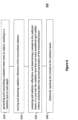
- Figure 6 is a high level flowchart illustrating a method 600 according to embodiments of the present invention.
- Method 600 includes the following steps: generating and transmitting a radiation beam onto an object, resulting in a radiation spot on said object 610; sensing and obtaining radiation reflections coming back from said object, wherein the radiation beam is generated in a way that reflections from different ranges are distinguishable of each other 620; and analyzing said radiation reflections, and determining a remedy to the radiation beam, in a case that said radiation spot does not meet predefined spot validity criteria 630.
- the generation step 610 and the sensing step 620 may be carried out at the same location (co-located). Additionally the generation parameters of step 610 are known and used in the analyzing step 630 for improving the analysis of the spot quality.
- the radiation beam is generated in a way that reflections from different ranges are distinguishable of each other. This is be achieved, without limiting to a specific structure or implementation, by generating a pulsed and/or modulated radiation beam and by timing the radiation sensor with the pulses and/or the modulation. One measurement is time-of-flight applied to the returning pulses so as to distinguish the range of their origin.
- the sensing step 620 further includes determining for each sensed reflection, a time of arrival and at least one of: a location of arrival, an angle of arrival, and a magnitude of the reflection.
- the analyzing further comprises determining a deviation from said predefined spot validity criteria based on at least one of: the time of arrival, the location of arrival, and the angle of arrival of the reflections, and configured to determine the remedy further based on the magnitude of the reflections.
- the method further includes the step of actually applying the remedy that has been determined, to the electromagnetic radiation 640 thus achieving a valid spot.
- FIGS 7A-7D are diagrams illustrating further non-limiting examples the system according to embodiments of the present invention. It is understood that many other applications may be implementing embodiments of the present invention.
- FIG. 7A is a block diagram according to some embodiments of the present invention in which radiation source 710 is a radio frequency (RF) source such as a directional antenna and wherein the system is incorporated within a communication system or a radar system.
- RF radio frequency
- directional antenna can be used to focus an RF beam at an antenna-receiver 720.
- a beam adjustment process may repeatedly analyze and improve the quality of the beam by analyzing the reflections coming from antenna 720.
- the coverage, as well as the uniformity of the beam can me monitored.
- Figures 7B is a block diagram according to some embodiments of the present invention in which radiation source 710 is a laser source (pointer analyzer) configured to generate a laser beam which may be transmitted onto a target 740.
- radiation source 710 is a laser source (pointer analyzer) configured to generate a laser beam which may be transmitted onto a target 740.
- the system may be incorporated within a laser pointing system in which the quality of the laser indicator is monitored.
- the laser beam may be used for speckle pattern analysis for remote sensing and seismic sensing applications.
- FIG. 7C is a block diagram according to some embodiments of the present invention in which radiation source 750 may be a visible light beam projector configured to generate a light beam generating a spot 770 on the ground. As shown the projector is connected to a watch tower 750 and another projector is connected to watch tower 760. Both projectors may operate together; each projector may be configured to analyze each other's spot by receiving the other projector's reflection sand analyzing them.
- FIG. 7D is a block diagram according to some embodiments of the present invention in which radiation source 710 may be a visible light beam projector configured to generate a light beam. As shown the projector is connected to a helicopter 780 illuminating a spot 790 over the ground, for searching purposes. In other examples, system may be incorporated within an illumination system, used for homeland security and other controlled illuminating purposes.
- radiation source 710 may be a visible light beam projector configured to generate a light beam.
- the projector is connected to a helicopter 780 illuminating a spot 790 over the ground, for searching purposes.
- system may be incorporated within an illumination system, used for homeland security and other controlled illuminating purposes.
- aspects of the present invention may be embodied as a system, method or an apparatus. Accordingly, aspects of the present invention may take the form of an entirely hardware embodiment, an entirely software embodiment (including firmware, resident software, micro-code, etc.) or an embodiment combining software and hardware aspects that may all generally be referred to herein as a "circuit,” “module” or “system.”
- each block in the flowchart or block diagrams may represent a module, segment, or portion of code, which comprises one or more executable instructions for implementing the specified logical function(s).
- the functions noted in the block may occur out of the order noted in the figures. For example, two blocks shown in succession may, in fact, be executed substantially concurrently, or the blocks may sometimes be executed in the reverse order, depending upon the functionality involved.
- method may refer to manners, means, techniques and procedures for accomplishing a given task including, but not limited to, those manners, means, techniques and procedures either known to, or readily developed from known manners, means, techniques and procedures by practitioners of the art to which the invention belongs.
- the present invention may be implemented in the testing or practice with methods and materials equivalent or similar to those described herein.
Landscapes
- Engineering & Computer Science (AREA)
- Computer Networks & Wireless Communication (AREA)
- Physics & Mathematics (AREA)
- General Physics & Mathematics (AREA)
- Radar, Positioning & Navigation (AREA)
- Remote Sensing (AREA)
- General Engineering & Computer Science (AREA)
- Optical Radar Systems And Details Thereof (AREA)
- Length Measuring Devices By Optical Means (AREA)
- Investigating Or Analysing Materials By Optical Means (AREA)
Description
- The present invention relates generally to the field of illumination sources based on electromagnetic radiation, and more particularly to determining the validity of radiation spots generated by such sources.
- One challenge in producing an electromagnetic radiation spot generated by a one or more illumination sources (e.g., a laser or other radiating sources) is to ensure that the radiation spot transmitted onto a remote object meets predefined quality criteria such as, but not limited to: spot size, spot shape, overall energy applied to the illumination surface, energetic uniformity of the spot, and the alignment of the spot vis à vis the illuminated objet in the sense of borders, coverage and energy containment. The term "spot validity" as used herein relates to the level of compliance of a certain spot with the quality criteria mentioned above.
- Japanese patent
JPS5944595 (B2 - According to one embodiment of the present invention, there is provided a system for analyzing quality criteria of a radiation spot. The system includes: at least one controllable electromagnetic light source configured to generate and transmit a pulsed light beam onto an object, resulting in a light spot on said object; at least one radiation sensor configured to sense and obtain light reflections of said pulsed light beam; an analyzer configured to: i) analyze a magnitude of said light reflections to deduce whether said light spot has partially missed said target; ii) analyze a delay from each other of said light reflections to deduce whether said light spot is misaligned with said target; and, determine a remedy to the light beam, in a case that said light spot does not meet predefined spot validity criteria; at least one remedy module configured to receive the remedy to the light beam from the analyzer and apply the remedy to the at least one controllable electromagnetic light source; and a controller configured to control said at least one controllable electromagnetic light source based on radiation adjustments generated by the at least one remedy module, and at least one drive physically coupled to the at least one controllable electromagnetic light source and wherein the controller is configured to instruct the at least one drive to adjust the spatial orientation and/or beam divergence of the at least one controllable electromagnetic light source, wherein said predefined spot validity criteria comprises at least one of: shape of the light spot, size of the light spot, and location of the light spot relative to boundaries of the object, and wherein the analyzer uses time-of-flight parameters of the light reflections to distinguish between light reflections coming from different ranges.
- According to one embodiment of the present invention, there is provided a method of analyzing quality criteria of a radiation spot. The method includes the followings steps: generating and transmitting a pulsed light beam onto an object, resulting in a light spot on said object; sensing and obtaining light reflections coming back; analyzing a magnitude of said light reflections to deduce whether said light spot has partially missed said target; analyzing a delay from each other of said light reflections to deduce whether said light spot is misaligned with said target; determining a remedy to the light beam, in a case that said light spot does not meet predefined spot validity criteria; and, applying the remedy to the pulsed light beam, by instructing at least one drive physically coupled to at least one controllable radiation source of the pulsed light beam, to adjust the spatial orientation and/or beam divergence of the at least one controllable radiation source, based on the remedy; wherein said predefined spot validity criteria comprises at least one of: shape of the light spot, size of the light spot, and location of the light spot relative to boundaries of the object, and wherein the analyzing utilizes time-of-flight parameters of the light reflections to distinguish between light reflections coming from different ranges.
- For a better understanding of the invention and in order to show how it may be implemented, references are made, purely by way of example, to the accompanying drawings in which like numerals designate corresponding elements or sections. In the accompanying drawings:
-
Figure 1 is a block diagram illustrating a system according to some embodiments of the present invention; -
Figure 2 is a detailed block diagram illustrating an aspect according to some embodiments of the present invention; -
Figures 3A and 3B are block diagrams illustrating non-limiting example of an operation of the system according to embodiments of the present invention; -
Figures 4A-4C are block diagrams illustrating further non-limiting example of an aspect of the system according to embodiments of the present invention; -
Figures 5A and 5B are diagrams illustrating further non-limiting example of an aspect of the system according to embodiments of the present invention; -
Figure 6 is a high level flowchart illustrating a method according to embodiments of the present invention; and -
Figures 7A-7D are diagrams illustrating further non-limiting examples the system according to embodiments of the present invention. - With specific reference now to the drawings in detail, it is stressed that the particulars shown are for the purpose of example and solely for discussing the preferred embodiments of the present invention, and are presented in the cause of providing what is believed to be the most useful and readily understood description of the principles and conceptual aspects of the invention. In this regard, no attempt is made to show structural details of the invention in more detail than is necessary for a fundamental understanding of the invention. The description taken with the drawings makes apparent to those skilled in the art how the several forms of the invention may be embodied in practice.
- Before explaining the embodiments of the invention in detail, it is to be understood that the invention is not limited in its application to the details of construction and the arrangement of the components set forth in the following descriptions or illustrated in the drawings. The invention is applicable to other embodiments and may be practiced or carried out in various ways. Also, it is to be understood that the phraseology and terminology employed herein is for the purpose of description and should not be regarded as limiting.
-
Figure 1 is a schematic block diagram illustrating a system according to some embodiments of the present invention.System 110 includes at least one controllableelectromagnetic radiation source 112 configured to generate and transmit aradiation beam 120 onto anobject 10, resulting in aradiation spot 130 onobject 10.System 110 further includes at least oneradiation sensor 114 configured to sense and obtain radiation reflections coming back from said object, wherein the radiation beam is generated in a way that reflections from different ranges are distinguishable of each other.System 110 further includes an analyzer configured to analyze said radiation reflections, and determine a remedy to the radiation beam, in a case that said radiation spot does not meet predefined spot validity criteria. The analyzer is further configured to determine for each sensed reflection, a time of arrival and at least one of: a location of arrival, an angle of arrival, and a magnitude of the reflection. - Spot validity level may be a quantitative measure indicating how much different the spot is from a preferred spot based on specific metrics. Specifically, the level of uniformity of the radiation throughout the spot, number of objects covered by the beam as well as its shape and size (e.g. diameter d) are all metrics of the radiation spot when considered as an indicator for validity purposes. A radiation spot may be considered compliant or non-compliant with the spot validity criteria, based on various variables including the specific purpose or application for which the spot is used.
- According to some embodiments of the present invention, the at least one controllable electromagnetic radiation source and the at least one radiation sensor are co-located and synchronized with each other.
- According to the present invention the radiation beam is generated in a way that reflections from different ranges are distinguishable of each other by generating a pulsed and/or modulated radiation beam and by synchronizing the radiation sensor with the pulses and/or the modulation.
- According to some embodiments of the present invention the analyzer is further configured to determine for each sensed reflection, a time of arrival and at least one of: a location of arrival, an angle of arrival, and a magnitude of the reflection.
- According to some embodiments of the present invention the analyzer is configured to determine a deviation from said predefined spot validity criteria based on at least one of: the time of arrival, the location of arrival, and the angle of arrival of the reflections, and configured to determine the remedy further based on the magnitude of the reflections.
- According to the present invention said predefined spot validity criteria comprise at least one of: shape of the radiation spot, size of the radiation spot, location of the radiation spot relative to boundaries of the object; and optionally energy uniformity of 20 the radiation spot.
- According to some embodiments of the present invention the at least one radiation sensor is configured to sense and obtain radiation reflections coming back from objects located more than 10km from the radiation sensor.
- According to some embodiments of the present invention the at least one radiation sensor may have a dynamic range which is sufficient to sense and obtain radiation reflections coming back from objects located more than 10km from the radiation sensor and also as close as 1km from the radiation sensor.
- According to some embodiments of the present invention the radiation sensor is further associated with a resolution level that is sufficiently high to distinguish between reflections coming from different objects which are located within 5m from each other.
- According to some embodiments of the present invention radiation sensor comprises at least two independent radiation sensing units, wherein said analyzer is configured to receive for each of the reflections, an association with the respective independent sensing unit, a time of arrival, and magnitude.
- According the present invention, further comprising at least one remedy module configured to receive the remedy from the analyzer and apply the remedy to the controllable electromagnetic radiation source.
- According to some embodiments of the present invention further comprising a radiation manipulator configured to adjust radiation properties of the controllable electromagnetic radiation source, based on the remedy.
- According to the present invention the controllable electromagnetic radiation source is a controllable light source configured to generate a light beam and wherein the system further comprises controllable optics configured to adjust the light source's alignment with the scene.
- According to some embodiments of the present invention said controllable optics comprise a lens configured to move relative to an optical path of the light beam for spatially divert the light beam (e.g., along the optical path or perpendicularly to the optical path).
- According to the invention,
system 110 further includes a controller configured to control said radiation source based on the radiation adjustments generated by remedy module.System 110 further includes at least one drive/drives physically coupled toradiation source 110 and wherein the controller is configured to instruct the drive to adjust the spatial orientation and/or beam divergence of the radiation source. In some embodiments, the spatial adjustments by motor may assist aligning radiation source withspecified objet 10 so that an adequate level of energy is applied to specifiedobjet 10 and that only a level of energy under a defined threshold is allowed not to be reflected back from specifiedobjet 10 or even worse, reflected from a different object thus provide false reflections. -
Figure 2 is a diagram illustrating a non-limiting implementation of the system according to some embodiments of the present invention. Aradiation transmitter 240 transmits radiation viatelescope 250 and throughvariable divergence mechanism 230 and intobeam tilting mechanism 220 and then via a transmitted/receiver telescope 210 - into the scene and onto an object, creating a spot. - Reflections enter transmitted/
receiver telescope 210 and folded onto receiver (sensor) 280 which is configured to derive pulses from the coming reflections and associate each pulse with a direction and time of arrival. These metrics are fed into a computer processor 270 (possibly in a form of an FPGA) which analyzes the pulses and determine the spot validity. Additionallycomputer processor 270 calculates the adjustments to the beam. - Optionally, some of the adjustments may be carried optically without moving the system, by controlling the beam properties by diverging and diverting it using for example a movable lens/lenses configured to move realtive to the optical path of the radiation beam. In another embodiment, adaptive optics may be used for adjusting optical properties of the beam (e.g., tilt angle, divergence) without introducing any moving part.
- Tilting the system in its entirety is not necessary in embodiments in which the radiation source is configured to tilt the radiation beam optically (e.g., by diverging or diverting the beam) without any physical movement of the system or even the radiation source itself. In one embodiment, the entire system may be tilted mechanically so as to improve the alignment of the transmitted beam and the object.
- According to some embodiments of the present invention, spot validity is calculated, inter alia, based on a temporal analysis of the reflections that originated from a single transmitted beam For example: two or more reflections which arrive to the sensor at different times indicate that the beam undesirably covers more than one object. The analysis may be detailed enough to indicate how this deviation can be remedied.
- According to embodiment of the invention, the sensor need not move relative to the spot transmitted on the object. It is crucial that the radiation source will be adjusted so as to adjust the radiation spot on the object rather than adjusting the sensor to a given, uncontrolled spot on the object. Therefore, it would be irrelevant whether the spot is reflected onto the center of the sensor or onto its boundary. However, it would be advantageous for the radiation spot to be effectively at the center of the object having the spot transmitted thereon.
- According to some embodiments, the sensor may require a very high dynamic range enabling it to detect both very low signals (reflections coming from afar) and high signal (reflection coming from very near range). As both the radiation source and sensor are located at the same place, the angular difference between them may be monitored and controlled.
- According to some embodiments of the present invention, the aforementioned spatial and temporal analysis of the reflections may be achieved by using an array of sensors such as a matrix sensor. Alternatively, a plurality of discrete sensors may be used.. For example, a four-quarter sensor may be used to monitor the reflections. By using an array of sensors, the reflections are associated with a spatial direction or location which may be used, by way of example, to determine a potential cause for a degraded level of spot validity such as inaccurate direction to the object or unfitted spot size.
-
Figure 3A is a diagram illustrating non-limiting example of an operation of the illuminator-analyzer 110 according to embodiments of the present invention. Here non-target objects 12 and 14 reflect some of the radiation ofbeam 120 indicating, by untimely pulses fromreflections target object 10 is not illuminated properly. -
Figure 3B is a diagram illustrating non-limiting example in which targetobject 10 is not well aligned causing again a non-valid spot. Specifically, illuminator-analyzer 110 generates abeam 120 resulting in aspot 130 onobject 10. Sinceobject 10 is tilted, the spot is spread irregularly of a corner ofobject 10 thus thereflections 140A-140C fromsame object 10 may be recorded with a delay from each other which may indicate they are coming from different objects. A further analysis however would indicate that the spot is simply misaligned with its object and the delay may be treated with realigning thebeam 120 withtarget 10. -
Figures 4A-4C are block diagrams illustrating three possible non-limiting sensor/receivers.Figure 4A suggests amatrix detector 400A in which each element receives its own pulse and associates it with direction and time of arrival and then forwards the column by row data toanalyzer 410. According to some embodiments of the present invention the at least two independent radiation sensing units, form an array sensor configured to generate a matrix indicative of time of arrivals and magnitudes of the respective reflections. -
Figure 4B is asimpler detector 400B based on discrete detectors, possibly each for a quarter of the image. According to some embodiments of the present invention the at least two independent radiation sensing units Q1-Q2-Q3-Q4, form a four-quadrant sensor, wherein each of the sensing units in the four-quadrant is a discrete sensing unit connected separately toanalyzer 410. -
Figure 4C is ascanner detector 400C which may require analyzing the spot in a series of several scanning cycles. This will require addressing a potential error and latency in taking a decision regarding remedying the spot. Alternatively, the scanning sensor may be required to be sufficiently quick to collect all pulses of same time of arrival and detect difference between them. According to some embodiments of the present invention radiation sensor may be a scanning sensor comprising a single sensing unit configured to scan in accordance with a scanning pattern that is synchronized with the electromagnetic radiation source so as to enable correction of tempo-spatially misalignment of the reflections due to the scanning. In one embodiment, the sensor is a scanning line sensor having a vector that scans one axis to yield matrix coverage. -
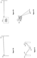
Figures 5A and 5B are diagrams illustrating further non-limiting example of an aspect of the system according to embodiments of the present invention. Specifically, the implemented sensor discussed is a four-quadrant sensor which assigns a reflection with each of its quadrant Q1-Q4. -
Figures 5A shows on the left side, a set-up of anilluminator analyzer 110 directing abeam 120 viailluminator 112 at anobject 10. As can be seen some part ofbeam 120 misses object 10 and therefore only some of the beam is being back reflected to be detected bysensor 114. The reflections as a function of time are shown in the pulse diagrams 510A where pulses associate with an exemplary fourquadrant sensor 410 having four discrete sensor Q1-Q4 are shown, Ingraph 510Apulses object 10 as detected by lower sensor units Q3 and Q4. The upper sensors Q1 and Q2 did not detect any pulse since the beam missed the object at its upper side. Analyzing the magnitudes of the pulses (or lack thereof) will enable the analyzer to deduce that the spot has partially missed the object. -
Figures 5B shows on the left side, a set-up of an illuminator analyzer producing abeam 120 viailluminator 112 which is split into two objects -object 12 being the object of interest and object 14 is in this case an object which leads to irrelevant pulses. This can be shown in the pulse diagrams 510B where it is evident that while Q3 andQ4 exhibit pulses object 10,pulses 511B and 511A present different magnitudes and a delay which can be analyzed (together with the magnitude) for recommending a suggested remedy. -
Figure 6 is a high level flowchart illustrating amethod 600 according to embodiments of the present invention.Method 600 includes the following steps: generating and transmitting a radiation beam onto an object, resulting in a radiation spot on saidobject 610; sensing and obtaining radiation reflections coming back from said object, wherein the radiation beam is generated in a way that reflections from different ranges are distinguishable of each other 620; and analyzing said radiation reflections, and determining a remedy to the radiation beam, in a case that said radiation spot does not meet predefinedspot validity criteria 630. - According to some embodiments of the present invention the
generation step 610 and thesensing step 620 may be carried out at the same location (co-located). Additionally the generation parameters ofstep 610 are known and used in the analyzingstep 630 for improving the analysis of the spot quality. - According to the present invention the radiation beam is generated in a way that reflections from different ranges are distinguishable of each other. This is be achieved, without limiting to a specific structure or implementation, by generating a pulsed and/or modulated radiation beam and by timing the radiation sensor with the pulses and/or the modulation. One measurement is time-of-flight applied to the returning pulses so as to distinguish the range of their origin.
- According to some embodiments of the present invention the
sensing step 620 further includes determining for each sensed reflection, a time of arrival and at least one of: a location of arrival, an angle of arrival, and a magnitude of the reflection. - According to some embodiments of the present invention the analyzing further comprises determining a deviation from said predefined spot validity criteria based on at least one of: the time of arrival, the location of arrival, and the angle of arrival of the reflections, and configured to determine the remedy further based on the magnitude of the reflections.
- According to the present invention the method further includes the step of actually applying the remedy that has been determined, to the
electromagnetic radiation 640 thus achieving a valid spot. -
Figures 7A-7D are diagrams illustrating further non-limiting examples the system according to embodiments of the present invention. It is understood that many other applications may be implementing embodiments of the present invention. -
Figure 7A is a block diagram according to some embodiments of the present invention in whichradiation source 710 is a radio frequency (RF) source such as a directional antenna and wherein the system is incorporated within a communication system or a radar system. - Specifically, directional antenna can be used to focus an RF beam at an antenna-
receiver 720. A beam adjustment process may repeatedly analyze and improve the quality of the beam by analyzing the reflections coming fromantenna 720. In radar applications, the coverage, as well as the uniformity of the beam can me monitored. -
Figures 7B is a block diagram according to some embodiments of the present invention in whichradiation source 710 is a laser source (pointer analyzer) configured to generate a laser beam which may be transmitted onto atarget 740. This way, the system may be incorporated within a laser pointing system in which the quality of the laser indicator is monitored. Alternatively the laser beam may be used for speckle pattern analysis for remote sensing and seismic sensing applications. -
Figures 7C is a block diagram according to some embodiments of the present invention in whichradiation source 750 may be a visible light beam projector configured to generate a light beam generating aspot 770 on the ground. As shown the projector is connected to awatch tower 750 and another projector is connected to watchtower 760. Both projectors may operate together; each projector may be configured to analyze each other's spot by receiving the other projector's reflection sand analyzing them. -
Figure 7D is a block diagram according to some embodiments of the present invention in whichradiation source 710 may be a visible light beam projector configured to generate a light beam. As shown the projector is connected to ahelicopter 780 illuminating aspot 790 over the ground, for searching purposes. In other examples, system may be incorporated within an illumination system, used for homeland security and other controlled illuminating purposes. - As will be appreciated by one skilled in the art, aspects of the present invention may be embodied as a system, method or an apparatus. Accordingly, aspects of the present invention may take the form of an entirely hardware embodiment, an entirely software embodiment (including firmware, resident software, micro-code, etc.) or an embodiment combining software and hardware aspects that may all generally be referred to herein as a "circuit," "module" or "system."
- The aforementioned flowchart and block diagrams illustrate the architecture, functionality, and operation of possible implementations of systems and methods according to various embodiments of the present invention. In this regard, each block in the flowchart or block diagrams may represent a module, segment, or portion of code, which comprises one or more executable instructions for implementing the specified logical function(s). It should also be noted that, in some alternative implementations, the functions noted in the block may occur out of the order noted in the figures. For example, two blocks shown in succession may, in fact, be executed substantially concurrently, or the blocks may sometimes be executed in the reverse order, depending upon the functionality involved. It will also be noted that each block of the block diagrams and/or flowchart illustration, and combinations of blocks in the block diagrams and/or flowchart illustration, can be implemented by special purpose hardware-based systems that perform the specified functions or acts, or combinations of special purpose hardware and computer instructions.
- In the above description, an embodiment is an example or implementation of the inventions. The various appearances of "one embodiment," "an embodiment" or "some embodiments" do not necessarily all refer to the same embodiments.
- Although various features of the invention may be described in the context of a single embodiment, the features may also be provided separately or in any suitable combination. Conversely, although the invention may be described herein in the context of separate embodiments for clarity, the invention may also be implemented in a single embodiment.
- Reference in the specification to "some embodiments", "an embodiment", "one embodiment" or "other embodiments" means that a particular feature, structure, or characteristic described in connection with the embodiments is included in at least some embodiments, but not necessarily all embodiments, of the inventions. It will further be recognized that the aspects of the invention described hereinabove may be combined or otherwise coexist in embodiments of the invention.
- It is to be understood that the phraseology and terminology employed herein is not to be construed as limiting and are for descriptive purpose only.
- The principles and uses of the teachings of the present invention may be better understood with reference to the accompanying description, figures and examples.
- It is to be understood that the details set forth herein do not construe a limitation to an application of the invention.
- Furthermore, it is to be understood that the invention can be carried out or practiced in various ways and that the invention can be implemented in embodiments other than the ones outlined in the description above.
- It is to be understood that the terms "including", "comprising", "consisting" and grammatical variants thereof do not preclude the addition of one or more components, features, steps, or integers or groups thereof and that the terms are to be construed as specifying components, features, steps or integers.
- If the specification or claims refer to "an additional" element, that does not preclude there being more than one of the additional element.
- It is to be understood that where the claims or specification refer to "a" or "an" element, such reference is not be construed that there is only one of that element.
- It is to be understood that where the specification states that a component, feature, structure, or characteristic "may", "might", "can" or "could" be included, that particular component, feature, structure, or characteristic is not required to be included.
- Where applicable, although state diagrams, flow diagrams or both may be used to describe embodiments, the invention is not limited to those diagrams or to the corresponding descriptions. For example, flow need not move through each illustrated box or state, or in exactly the same order as illustrated and described.
- The term "method" may refer to manners, means, techniques and procedures for accomplishing a given task including, but not limited to, those manners, means, techniques and procedures either known to, or readily developed from known manners, means, techniques and procedures by practitioners of the art to which the invention belongs.
- The descriptions, examples, methods and materials presented in the claims and the specification are not to be construed as limiting but rather as illustrative only.
- Meanings of technical and scientific terms used herein are to be commonly understood as by one of ordinary skill in the art to which the invention belongs, unless otherwise defined.
- The present invention may be implemented in the testing or practice with methods and materials equivalent or similar to those described herein.
- While the invention has been described with respect to a limited number of embodiments, these should not be construed as limitations on the scope of the invention, but rather as exemplifications of some of the preferred embodiments. Other possible variations, modifications, and applications are also within the scope of the invention as defined by the appended claims.
Claims (13)
- A system comprising:at least one controllable electromagnetic light source (112, 240, 750) configured to generate and transmit a pulsed light beam (120) onto an object (10, 740), resulting in a light spot (130, 770, 790) on said object;at least one radiation sensor (114, 280, 400A, 400B, 400C) configured to sense and obtain light reflections (140) of said pulsed light beam;an analyzer (110, 270, 410, 730) configured to:i) analyze a magnitude of said light reflections to deduce whether said light spot has partially missed said target;ii) analyze a delay from each other of said light reflections to deduce whether said light spot is misaligned with said target; and determine a remedy to the light beam, in a case that said light spot does not meet predefined spot validity criteria;at least one remedy module configured to receive the remedy to the light beam from the analyzer and apply the remedy to the at least one controllable electromagnetic light source; anda controller configured to control said at least one controllable electromagnetic light source based on radiation adjustments generated by the at least one remedy module, and at least one drive physically coupled to the at least one controllable electromagnetic light source and wherein the controller is configured to instruct the at least one drive to adjust the spatial orientation and/or beam divergence of the at least one controllable electromagnetic light source,wherein said predefined spot validity criteria comprises at least one of: shape of the light spot, size of the light spot, and location of the light spot relative to boundaries of the object, andwherein the analyzer uses time-of-flight parameters of the light reflections to distinguish between light reflections coming from different ranges.
- The system according to claim 1, wherein the at least one controllable electromagnetic light source and the at least one radiation sensor are co-located and synchronized with each other.
- The system according to claim 1, wherein the analyzer is further configured to determine a deviation from said predefined spot validity criteria based on an angle of arrival of the light reflections.
- The system according to claim 1, wherein the at least one radiation sensor is configured to sense and obtain light reflections coming back from one of:i) objects located more than 10km from the at least one radiation sensor;ii) objects located along a range from 1km to over 10km from the at least one radiation sensor; and,iii) objects located more than 10km from the at least one radiation sensor and further to distinguish between light reflections coming from different objects which are located within 5m or less from each other, the at least one radiation sensor having a dynamic range which is sufficient to sense and obtain said light reflections.
- The system according to claim 1, wherein said at least one radiation sensor comprises at least two independent radiation sensing units, wherein said analyzer is configured to receive for each of the light reflections, an association with the respective independent radiation sensing unit, a time of arrival, and magnitude.
- The system according to claim 1, wherein the at least one radiation sensor is configured to sense and obtain light reflections from objects located along a range from 1km to over 10km from the at least one radiation sensor, and wherein the radiation sensor is one of: a matrix sensor, a four-quadrant sensor, and a scanning line sensor.
- The system according to claim 1, further comprising a radiation manipulator configured to adjust properties of the at least one controllable electromagnetic light source, based on the remedy generated by the analyzer.
- The system according to claim 1, wherein the at least one controllable electromagnetic light source further comprises controllable optics configured to adjust the at least one controllable electromagnetic light source's alignment with the scene, said controllable optics comprising a lens configured to move relative to an optical path of the light beam to spatially divert the light beam, optionally along the optical path of the light beam.
- The system according to any preceding claim, wherein the at least one controllable electromagnetic light source is one of:i) a laser source configured to generate a laser beam and wherein the system is incorporated within a laser system; and,ii) a non-laser visible light beam projector configured to generate a light beam and wherein the system is incorporated within an illumination system.
- A method comprising:generating and transmitting a pulsed light beam (120) onto an object (10, 740), resulting in a light spot (130, 770, 790) on said object;sensing and obtaining light reflections (140) coming back;analyzing a magnitude of said light reflections to deduce whether said light spot has partially missed said target;analyzing a delay from each other of said light reflections to deduce whether said light spot is misaligned with said target;determining a remedy to the light beam, in a case that said light spot does not meet predefined spot validity criteria; andapplying the remedy to the pulsed light beam, by instructing at least one drive physically coupled to at least one controllable radiation source of the pulsed light beam, to adjust the spatial orientation and/or beam divergence of the at least one controllable radiation source, based on the remedy,wherein said predefined spot validity criteria comprises at least one of: shape of the light spot, size of the light spot, and location of the light spot relative to boundaries of the object,and wherein the analyzing utilizes time-of-flight parameters of the light reflections to distinguish between light reflections coming from different ranges.
- The method according to claim 10, wherein the generation and the sensing are co-located and synchronized with each other.
- The method according to claim 10, wherein the analyzing further comprises determining a deviation from said predefined spot validity criteria based on an angle of arrival of the light reflections.
- The method according to claim 10, wherein the sensing comprises sensing light reflections coming back from one of:i) objects located beyond 10km; and,ii) objects located beyond 10km and further distinguishing between light reflections coming from different objects which are located within 5m from each other.
Applications Claiming Priority (2)
| Application Number | Priority Date | Filing Date | Title |
|---|---|---|---|
| IL233692A IL233692A (en) | 2014-07-17 | 2014-07-17 | System and method for analyzing quality criteria of a radiation spot |
| PCT/IL2015/050740 WO2016009440A1 (en) | 2014-07-17 | 2015-07-19 | System and method for analyzing quality criteria of a radiation spot |
Publications (4)
| Publication Number | Publication Date |
|---|---|
| EP3170024A1 EP3170024A1 (en) | 2017-05-24 |
| EP3170024A4 EP3170024A4 (en) | 2018-05-30 |
| EP3170024B1 true EP3170024B1 (en) | 2025-03-05 |
| EP3170024C0 EP3170024C0 (en) | 2025-03-05 |
Family
ID=54070634
Family Applications (1)
| Application Number | Title | Priority Date | Filing Date |
|---|---|---|---|
| EP15822362.8A Active EP3170024B1 (en) | 2014-07-17 | 2015-07-19 | System and method for analyzing quality criteria of a radiation spot |
Country Status (6)
| Country | Link |
|---|---|
| US (1) | US11822021B2 (en) |
| EP (1) | EP3170024B1 (en) |
| KR (1) | KR102422130B1 (en) |
| CA (1) | CA2955417C (en) |
| IL (1) | IL233692A (en) |
| WO (1) | WO2016009440A1 (en) |
Families Citing this family (5)
| Publication number | Priority date | Publication date | Assignee | Title |
|---|---|---|---|---|
| FR3050814B1 (en) | 2016-04-29 | 2019-06-07 | Airbus Helicopters | METHOD AND DEVICE FOR ASSISTED AID FOR LASER GUIDANCE OF A PROJECTILE |
| CN106291512B (en) * | 2016-07-29 | 2018-11-27 | 中国科学院光电研究院 | A kind of method of array push-broom type laser radar range Nonuniformity Correction |
| CN109163609B (en) * | 2018-08-13 | 2020-12-22 | 上海机电工程研究所 | Calibration method for radio frequency-optical common-caliber composite target simulation system |
| ES2942576T3 (en) | 2018-11-20 | 2023-06-02 | Simulacions Optiques S L | Verification device for an integrated circuit with an optoelectronic transmitter, manufacturing system and associated verification and manufacturing process |
| IL268654B (en) * | 2019-08-12 | 2021-02-28 | Elbit Systems Land & C4I Ltd | Optical seismic surveying system |
Family Cites Families (18)
| Publication number | Priority date | Publication date | Assignee | Title |
|---|---|---|---|---|
| US3968362A (en) * | 1975-08-11 | 1976-07-06 | Honeywell Inc. | Optical system for laser doppler homodyne detection |
| JPS5944595B2 (en) | 1980-01-24 | 1984-10-30 | 日本電気株式会社 | Laser device |
| JPS614263A (en) | 1984-06-19 | 1986-01-10 | Nippon Mining Co Ltd | Connecting tape for automatic gang bonding |
| US4600305A (en) * | 1984-08-20 | 1986-07-15 | The United States Of America As Represented By The Secretary Of The Army | Dynamic energy centroid locator and processor (declp) |
| US4737028A (en) * | 1986-04-07 | 1988-04-12 | The United States Of America As Represented By The Secretary Of The Army | Target loop active boresighting device |
| US4891772A (en) * | 1987-04-15 | 1990-01-02 | Cyberoptics Corporation | Point and line range sensors |
| US5784023A (en) * | 1995-06-26 | 1998-07-21 | Bluege; John | Speed detection method |
| US5988862A (en) * | 1996-04-24 | 1999-11-23 | Cyra Technologies, Inc. | Integrated system for quickly and accurately imaging and modeling three dimensional objects |
| AU3147897A (en) * | 1996-05-31 | 1998-01-05 | Cinram, Inc. | System for adjusting the spot size in an optical recording system |
| AUPR301401A0 (en) * | 2001-02-09 | 2001-03-08 | Commonwealth Scientific And Industrial Research Organisation | Lidar system and method |
| DE10124433A1 (en) * | 2001-05-18 | 2002-11-21 | Bosch Gmbh Robert | Device for optical distance measurement has components that allow easy variation of the beam path direction and divergence to match the target type and distance |
| US20030030582A1 (en) * | 2001-08-10 | 2003-02-13 | Vickers Roger S. | Environment measurement methods, systems, media, signals and data structures |
| US8586932B2 (en) | 2004-11-09 | 2013-11-19 | Spectrum Dynamics Llc | System and method for radioactive emission measurement |
| WO2005076037A1 (en) | 2004-02-04 | 2005-08-18 | Elbit Systems Ltd. | Gated imaging |
| US8447563B2 (en) * | 2009-03-31 | 2013-05-21 | The United States Of America As Represented By The Secretary Of The Navy | Method and system for determination of detection probability or a target object based on a range |
| US8797828B1 (en) * | 2010-02-15 | 2014-08-05 | Soreq NRC | Remote optical seismic surveying and detection and imaging of underground objects |
| US9612115B2 (en) * | 2012-06-07 | 2017-04-04 | Trackingpoint, Inc. | Target-correlated electronic rangefinder |
| WO2018126248A1 (en) * | 2017-01-02 | 2018-07-05 | Okeeffe James | Micromirror array for feedback-based image resolution enhancement |
-
2014
- 2014-07-17 IL IL233692A patent/IL233692A/en active IP Right Grant
-
2015
- 2015-07-19 WO PCT/IL2015/050740 patent/WO2016009440A1/en not_active Ceased
- 2015-07-19 KR KR1020177004459A patent/KR102422130B1/en active Active
- 2015-07-19 US US15/326,656 patent/US11822021B2/en active Active
- 2015-07-19 EP EP15822362.8A patent/EP3170024B1/en active Active
- 2015-07-19 CA CA2955417A patent/CA2955417C/en active Active
Also Published As
| Publication number | Publication date |
|---|---|
| KR102422130B1 (en) | 2022-07-20 |
| EP3170024A1 (en) | 2017-05-24 |
| IL233692A0 (en) | 2015-06-30 |
| IL233692A (en) | 2017-04-30 |
| US20170205498A1 (en) | 2017-07-20 |
| EP3170024C0 (en) | 2025-03-05 |
| CA2955417C (en) | 2023-03-14 |
| EP3170024A4 (en) | 2018-05-30 |
| KR20170090401A (en) | 2017-08-07 |
| US11822021B2 (en) | 2023-11-21 |
| CA2955417A1 (en) | 2016-01-21 |
| WO2016009440A1 (en) | 2016-01-21 |
Similar Documents
| Publication | Publication Date | Title |
|---|---|---|
| US20210356567A1 (en) | HIGH RESOLUTION LiDAR USING HIGH FREQUENCY PULSE FIRING | |
| EP3187895B1 (en) | Variable resolution light radar system | |
| US10795023B2 (en) | Laser scanning apparatus and method | |
| US10365352B2 (en) | Distance measurement instrument with scanning function | |
| US10838044B2 (en) | Electromagnetic wave detection apparatus and information acquisition system | |
| CA2955417C (en) | System and method for analyzing quality criteria of a radiation spot | |
| US8384914B2 (en) | Device for optically scanning and measuring an environment | |
| EP2426459B1 (en) | Measuring method and measuring device | |
| EP3869152B1 (en) | Surveying device with a coaxial beam deflection element | |
| JP2020501130A5 (en) | ||
| JP2019537013A5 (en) | ||
| US10459242B2 (en) | Method and device for capturing an image of a target object | |
| JP2021509569A5 (en) | A method for ensuring safety in a multi-beam wireless power transmission system, and a system for transmitting wireless power. | |
| US20180106894A1 (en) | Distance measuring apparatus and distance measuring method | |
| US10073165B2 (en) | Distance measurement instrument with scanning function | |
| US10585185B2 (en) | Security scanning system with walk-through-gate | |
| EP3447535B1 (en) | 3-dimensional measuring device | |
| US20010012145A1 (en) | Optical scanning device | |
| JP7007637B2 (en) | Laser ranging device, laser ranging method and position adjustment program | |
| US9851442B1 (en) | LADAR augmented infra-red (LAIR) sensor | |
| KR101938774B1 (en) | Composite Sensor Homming Device and System | |
| US20230161040A1 (en) | Electromagnetic wave detection apparatus and range finder | |
| JP2020533559A (en) | Active seeker head system | |
| JP2018155658A (en) | Object detection apparatus, object detection method, and object detection program | |
| KR101604321B1 (en) | Ground alignment appratus of array antenna and control method thereof |
Legal Events
| Date | Code | Title | Description |
|---|---|---|---|
| STAA | Information on the status of an ep patent application or granted ep patent |
Free format text: STATUS: THE INTERNATIONAL PUBLICATION HAS BEEN MADE |
|
| PUAI | Public reference made under article 153(3) epc to a published international application that has entered the european phase |
Free format text: ORIGINAL CODE: 0009012 |
|
| STAA | Information on the status of an ep patent application or granted ep patent |
Free format text: STATUS: REQUEST FOR EXAMINATION WAS MADE |
|
| 17P | Request for examination filed |
Effective date: 20170216 |
|
| AK | Designated contracting states |
Kind code of ref document: A1 Designated state(s): AL AT BE BG CH CY CZ DE DK EE ES FI FR GB GR HR HU IE IS IT LI LT LU LV MC MK MT NL NO PL PT RO RS SE SI SK SM TR |
|
| AX | Request for extension of the european patent |
Extension state: BA ME |
|
| DAV | Request for validation of the european patent (deleted) | ||
| DAX | Request for extension of the european patent (deleted) | ||
| A4 | Supplementary search report drawn up and despatched |
Effective date: 20180426 |
|
| RIC1 | Information provided on ipc code assigned before grant |
Ipc: G01S 7/483 20060101AFI20180420BHEP Ipc: F41G 3/14 20060101ALI20180420BHEP Ipc: F41G 3/32 20060101ALI20180420BHEP Ipc: G01S 7/40 20060101ALI20180420BHEP Ipc: G01S 7/486 20060101ALI20180420BHEP Ipc: G01S 7/497 20060101ALI20180420BHEP Ipc: F41G 7/22 20060101ALI20180420BHEP |
|
| STAA | Information on the status of an ep patent application or granted ep patent |
Free format text: STATUS: EXAMINATION IS IN PROGRESS |
|
| 17Q | First examination report despatched |
Effective date: 20190207 |
|
| REG | Reference to a national code |
Ref country code: DE Ref legal event code: R079 Free format text: PREVIOUS MAIN CLASS: G01S0017660000 Ipc: G01S0007483000 Ref document number: 602015091168 Country of ref document: DE |
|
| GRAP | Despatch of communication of intention to grant a patent |
Free format text: ORIGINAL CODE: EPIDOSNIGR1 |
|
| STAA | Information on the status of an ep patent application or granted ep patent |
Free format text: STATUS: GRANT OF PATENT IS INTENDED |
|
| RIC1 | Information provided on ipc code assigned before grant |
Ipc: F41G 3/14 20060101ALI20241018BHEP Ipc: F41G 7/22 20060101ALI20241018BHEP Ipc: G01S 7/497 20060101ALI20241018BHEP Ipc: G01S 7/40 20060101ALI20241018BHEP Ipc: F41G 3/32 20060101ALI20241018BHEP Ipc: G01S 7/4863 20200101ALI20241018BHEP Ipc: G01S 7/483 20060101AFI20241018BHEP |
|
| INTG | Intention to grant announced |
Effective date: 20241119 |
|
| GRAS | Grant fee paid |
Free format text: ORIGINAL CODE: EPIDOSNIGR3 |
|
| GRAA | (expected) grant |
Free format text: ORIGINAL CODE: 0009210 |
|
| STAA | Information on the status of an ep patent application or granted ep patent |
Free format text: STATUS: THE PATENT HAS BEEN GRANTED |
|
| AK | Designated contracting states |
Kind code of ref document: B1 Designated state(s): AL AT BE BG CH CY CZ DE DK EE ES FI FR GB GR HR HU IE IS IT LI LT LU LV MC MK MT NL NO PL PT RO RS SE SI SK SM TR |
|
| REG | Reference to a national code |
Ref country code: GB Ref legal event code: FG4D |
|
| REG | Reference to a national code |
Ref country code: CH Ref legal event code: EP |
|
| REG | Reference to a national code |
Ref country code: DE Ref legal event code: R096 Ref document number: 602015091168 Country of ref document: DE |
|
| REG | Reference to a national code |
Ref country code: IE Ref legal event code: FG4D |
|
| U01 | Request for unitary effect filed |
Effective date: 20250311 |
|
| U07 | Unitary effect registered |
Designated state(s): AT BE BG DE DK EE FI FR IT LT LU LV MT NL PT RO SE SI Effective date: 20250319 |
|
| PG25 | Lapsed in a contracting state [announced via postgrant information from national office to epo] |
Ref country code: RS Free format text: LAPSE BECAUSE OF FAILURE TO SUBMIT A TRANSLATION OF THE DESCRIPTION OR TO PAY THE FEE WITHIN THE PRESCRIBED TIME-LIMIT Effective date: 20250605 |
|
| PG25 | Lapsed in a contracting state [announced via postgrant information from national office to epo] |
Ref country code: ES Free format text: LAPSE BECAUSE OF FAILURE TO SUBMIT A TRANSLATION OF THE DESCRIPTION OR TO PAY THE FEE WITHIN THE PRESCRIBED TIME-LIMIT Effective date: 20250305 |
|
| PGFP | Annual fee paid to national office [announced via postgrant information from national office to epo] |
Ref country code: GB Payment date: 20250529 Year of fee payment: 11 |
|
| PG25 | Lapsed in a contracting state [announced via postgrant information from national office to epo] |
Ref country code: NO Free format text: LAPSE BECAUSE OF FAILURE TO SUBMIT A TRANSLATION OF THE DESCRIPTION OR TO PAY THE FEE WITHIN THE PRESCRIBED TIME-LIMIT Effective date: 20250605 |
|
| PG25 | Lapsed in a contracting state [announced via postgrant information from national office to epo] |
Ref country code: HR Free format text: LAPSE BECAUSE OF FAILURE TO SUBMIT A TRANSLATION OF THE DESCRIPTION OR TO PAY THE FEE WITHIN THE PRESCRIBED TIME-LIMIT Effective date: 20250305 |
|
| U20 | Renewal fee for the european patent with unitary effect paid |
Year of fee payment: 11 Effective date: 20250606 |
|
| PG25 | Lapsed in a contracting state [announced via postgrant information from national office to epo] |
Ref country code: GR Free format text: LAPSE BECAUSE OF FAILURE TO SUBMIT A TRANSLATION OF THE DESCRIPTION OR TO PAY THE FEE WITHIN THE PRESCRIBED TIME-LIMIT Effective date: 20250606 |
|
| PG25 | Lapsed in a contracting state [announced via postgrant information from national office to epo] |
Ref country code: SM Free format text: LAPSE BECAUSE OF FAILURE TO SUBMIT A TRANSLATION OF THE DESCRIPTION OR TO PAY THE FEE WITHIN THE PRESCRIBED TIME-LIMIT Effective date: 20250305 |
|
| PG25 | Lapsed in a contracting state [announced via postgrant information from national office to epo] |
Ref country code: PL Free format text: LAPSE BECAUSE OF FAILURE TO SUBMIT A TRANSLATION OF THE DESCRIPTION OR TO PAY THE FEE WITHIN THE PRESCRIBED TIME-LIMIT Effective date: 20250305 |
|
| PG25 | Lapsed in a contracting state [announced via postgrant information from national office to epo] |
Ref country code: CZ Free format text: LAPSE BECAUSE OF FAILURE TO SUBMIT A TRANSLATION OF THE DESCRIPTION OR TO PAY THE FEE WITHIN THE PRESCRIBED TIME-LIMIT Effective date: 20250305 |
|
| PG25 | Lapsed in a contracting state [announced via postgrant information from national office to epo] |
Ref country code: SK Free format text: LAPSE BECAUSE OF FAILURE TO SUBMIT A TRANSLATION OF THE DESCRIPTION OR TO PAY THE FEE WITHIN THE PRESCRIBED TIME-LIMIT Effective date: 20250305 |
|
| PG25 | Lapsed in a contracting state [announced via postgrant information from national office to epo] |
Ref country code: IS Free format text: LAPSE BECAUSE OF FAILURE TO SUBMIT A TRANSLATION OF THE DESCRIPTION OR TO PAY THE FEE WITHIN THE PRESCRIBED TIME-LIMIT Effective date: 20250705 |
|
| PLBE | No opposition filed within time limit |
Free format text: ORIGINAL CODE: 0009261 |
|
| STAA | Information on the status of an ep patent application or granted ep patent |
Free format text: STATUS: NO OPPOSITION FILED WITHIN TIME LIMIT |
|
| REG | Reference to a national code |
Ref country code: CH Ref legal event code: L10 Free format text: ST27 STATUS EVENT CODE: U-0-0-L10-L00 (AS PROVIDED BY THE NATIONAL OFFICE) Effective date: 20260114 |
|
| 26N | No opposition filed |
Effective date: 20251208 |
|
| REG | Reference to a national code |
Ref country code: CH Ref legal event code: H13 Free format text: ST27 STATUS EVENT CODE: U-0-0-H10-H13 (AS PROVIDED BY THE NATIONAL OFFICE) Effective date: 20260224 |
|
| PG25 | Lapsed in a contracting state [announced via postgrant information from national office to epo] |
Ref country code: CH Free format text: LAPSE BECAUSE OF NON-PAYMENT OF DUE FEES Effective date: 20250731 |
|
| U1N | Appointed representative for the unitary patent procedure changed after the registration of the unitary effect |
Representative=s name: MARKS & CLERK LLP; GB |