EP3169555B1 - Antitheft device for a steering column of a vehicle provided with a bolt lifting with a low key torque - Google Patents
Antitheft device for a steering column of a vehicle provided with a bolt lifting with a low key torque Download PDFInfo
- Publication number
- EP3169555B1 EP3169555B1 EP15734667.7A EP15734667A EP3169555B1 EP 3169555 B1 EP3169555 B1 EP 3169555B1 EP 15734667 A EP15734667 A EP 15734667A EP 3169555 B1 EP3169555 B1 EP 3169555B1
- Authority
- EP
- European Patent Office
- Prior art keywords
- slider
- antitheft device
- movement
- locking bolt
- cavity
- Prior art date
- Legal status (The legal status is an assumption and is not a legal conclusion. Google has not performed a legal analysis and makes no representation as to the accuracy of the status listed.)
- Active
Links
Images

Classifications
-
- B—PERFORMING OPERATIONS; TRANSPORTING
- B60—VEHICLES IN GENERAL
- B60R—VEHICLES, VEHICLE FITTINGS, OR VEHICLE PARTS, NOT OTHERWISE PROVIDED FOR
- B60R25/00—Fittings or systems for preventing or indicating unauthorised use or theft of vehicles
- B60R25/01—Fittings or systems for preventing or indicating unauthorised use or theft of vehicles operating on vehicle systems or fittings, e.g. on doors, seats or windscreens
- B60R25/02—Fittings or systems for preventing or indicating unauthorised use or theft of vehicles operating on vehicle systems or fittings, e.g. on doors, seats or windscreens operating on the steering mechanism
- B60R25/021—Fittings or systems for preventing or indicating unauthorised use or theft of vehicles operating on vehicle systems or fittings, e.g. on doors, seats or windscreens operating on the steering mechanism restraining movement of the steering column or steering wheel hub, e.g. restraining means controlled by ignition switch
- B60R25/0211—Fittings or systems for preventing or indicating unauthorised use or theft of vehicles operating on vehicle systems or fittings, e.g. on doors, seats or windscreens operating on the steering mechanism restraining movement of the steering column or steering wheel hub, e.g. restraining means controlled by ignition switch comprising a locking member radially and linearly moved towards the steering column
- B60R25/02115—Fittings or systems for preventing or indicating unauthorised use or theft of vehicles operating on vehicle systems or fittings, e.g. on doors, seats or windscreens operating on the steering mechanism restraining movement of the steering column or steering wheel hub, e.g. restraining means controlled by ignition switch comprising a locking member radially and linearly moved towards the steering column key actuated
Definitions
- the invention relates to an antitheft device for a steering column of a vehicle.
- These devices generally include a latch of an ignition key of the vehicle, as well as a bolt adapted to lock the movement of the steering column of a car.
- the main function of such devices is to lock the movement of the steering column whenever this movement is not authorized.
- An antitheft device according to the preamble of claim 1 is known from FR 2 885 632 A1 .
- the unlocking of the antitheft device is done by turning the key into the latch.
- such movement requires a certain force that must be applied by a human hand.
- the force to apply can prove difficult for certain person, such as old or arm/wrist injured people.
- a worn out key forced upon the latch to unlock the steering column can snap under the heavy torque applied. This can prove bothersome as well as painful for the vehicle user.
- One object of the invention is to provide an antitheft device for a steering column of a vehicle, in particular a bolt designed such as the antitheft device does not present the drawbacks mentioned hereinabove.
- the invention proposes an antitheft device for a steering column of a vehicle according to claim 1.
- the antitheft device according to the invention provides a bolt lifting movement with a low key torque.
- the unlocking of the antitheft device is smoother, providing a safest movement for the user.
- the invention also relates to a vehicle comprising an antitheft device according to the invention.
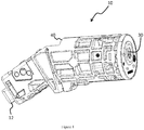
- Figure 1 represents an isometric overview of an antitheft device 10 as isolated from a vehicle.
- the device comprises a latch 30 for a key, which, when turned, permits the ignition of the motor and actuate a locking bolt 12 to occupy a position to lock the steering column 20 (not shown in figure 1 ) of the vehicle.
- the antitheft mechanism is enclosed in a housing 40.
- the housing 40 is then embedded in a vehicle.
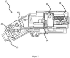
- FIG. 2 shows a partial cut-away view of the antitheft device wherein the main elements of the invention are visible.
- the rotor 18 rotates, dragging along the camshaft 16.
- the camshaft 16 comprises a uniform slope that permits, when rotating, to induce a uniform translating movement to the slider 14.
- the slider 14 translates within a slide in the housing 40 to enable a movement on a horizontal axis only.
- the slider 14 then drags along the locking bolt 12, which is located in a bolt housing 42, the bolt housing 42 embedded in the housing 40.
- the bolt housing 42 allows the bolt 12 to slide in only one axis and to interact with the steering column.
- the actuation of the rotor 18 using the key controls the position of the locking bolt 12, thus blocking or unblocking the steering column.
- the steering column 20 shown on figure 3 comprises a slot 22 adapted to receive the bolt 12 which permits the locking in position of the steering column 20 about its axis of rotation. Whenever the steering column 20 is in its locked position, and if a torque is applied to the column axis, the steering column 20 applies a force on the bolt 12. This force, depending on its intensity, is a source of the difficulty (or impossibility) to unlock the steering column 20 by solely turning the key in the latch 30.
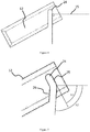
- FIG 4 shows a prior art locking bolt 12.
- the locking bolt 12 has a parallelepiped shape and comprises a U-shaped cavity 24 characterized by two parallel flat ramps.
- the end of the cavity 24 has a rounded shape, and the cavity 24 being U-shaped, the opposite side is open.
- the cavity 24 is oriented perpendicularly to the direction of movement 15 of the slider 14.
- the slider 14 interacts with the cavity 24 of the locking bolt 12 by sliding along the ramp in the cavity 24.
- the locking bolt 12 slides along the direction of the bolt housing 42.
- the force needed to translate the slider 14 is higher than the force needed to move the locking bolt 12. Consequently, the torque that has to be applied to the key in the latch 30 is high and it often proves difficult for a human hand to actuate the key in the latch 30.
- the present invention aims at easing the unlocking of the steering column 20 by improving the design of the bolt 12 in order to reduce the torque that the vehicle user needs to apply to the key to unlock the steering column 20.
- Figure 5 shows a design for the bolt 12 according to one embodiment of the invention.
- the bolt 12 has a parallelepiped shape and comprises a cavity 24.
- the cavity 24, contrary to one of the prior art locking bolt, is separated in two portions.
- Each portion comprises two parallel ramps, both characterized by their angle relative to the direction of movement 15 of the slider 14.
- the first portion 25 is designed such as its angle A1 relative to the direction of movement 15 of the slider 14 is smaller than 90 degrees.
- the second portion 26 is designed such as its angle A2 relative to the direction of movement 15 of the slider 14 is greater than 90 degrees.
- the width of the cavity 24 is adapted so that the slider 14 moves along the cavity 24. This movement may be done without dead travel.
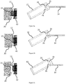
- Figures 6a to 6c represent the different positions of the slider within the cavity 24 of a bolt 12 according to one embodiment of the invention and the position of the bolt 12 in interaction with the steering column 20.
- the steering column 20 is blocked in position with the bolt 12 located in the slot 22 of the steering column 20. In this position, a pre-load is generally applied on the steering column 20. Therefore, the steering column 20 exerts a force on the bolt 12 that prevents the bolt 12 to be easily removed from the slot 22 of the steering column 20.
- the design of the first ramp 25 enables the slider 14 to move within the cavity 24 with a low force applied. During the sliding of the slider 14 on the first ramp 25, the stroke evolution of the bolt 12 is slow, but allows the bolt 12 to begin its course for the unlocking of the steering column 20 without requiring an important force from the user.
- the steering column 20 is close to the unlocked position.
- the bolt 12 is still in contact with the steering column 20 but the torque applied by the steering column 20 to the bolt 12 is negligible.
- the slider 14 is located at the end of the first portion 25, near the interface between the first portion 25 and the second portion 26. At this point, the force needed to be applied to the slider 14 is still low and the stroke evolution of the bolt 12 remains slow.
- the bolt 12 has completely left the slot 22 of the steering column 20. However, the bolt 12 needs to complete the stroke. At this point, the steering column 20 does not exert any force on the bolt 12. Thus, the force needed to translate the bolt 12 is very low.
- the slider 14 moves along the second portion 26 to finish the stroke of the bolt 12 and to finalize the unlocking action.
- the angle A2 between the ramp of the second portion 26 and the direction of movement 15 of the slider 14 is over 90 degrees, which increases the bolt stroke evolution, permitting to finish the stroke of the bolt 12.
- the angle between the direction of movement 15 of the slider 14 when interacting with the surface of the first portion 25 and the tangent plane to said surface increases monotonically from an angle smaller than 90° as the slider slides towards the interface between the first 25 and the second portion 26.
- the angle between the direction of movement 15 of the slider 14 when interacting with the surface of the first portion 25 and the tangent plane to said surface cannot be higher than 90°, at least on the first portion 25 of the cavity 24.
- the angle between the direction of movement 15 of the slider 14 when interacting with the surface of the second portion 26 and the tangent plane to said surface increases monotonically from an angle higher than 90° as the slider slides away from the interface between the first 25 and the second portion 26.
- angles considered in this embodiment are the complementary angles to 90° between the direction of movement 15 of the slider 14 and the normal of the tangent plane to the surface of whichever portion the slider is interacting with.
- the ramps are designed in such a way that the movement of the slider 14 within the cavity 24 ensures the entire unlocking movement of the antitheft device.
Landscapes
- Engineering & Computer Science (AREA)
- Mechanical Engineering (AREA)
- Lock And Its Accessories (AREA)
Description
- The invention relates to an antitheft device for a steering column of a vehicle.
- These devices generally include a latch of an ignition key of the vehicle, as well as a bolt adapted to lock the movement of the steering column of a car. The main function of such devices is to lock the movement of the steering column whenever this movement is not authorized.
- An antitheft device according to the preamble of claim 1 is known from
FR 2 885 632 A1 - Generally, the unlocking of the antitheft device is done by turning the key into the latch. However, such movement requires a certain force that must be applied by a human hand. Depending on the vehicle user, the force to apply can prove difficult for certain person, such as old or arm/wrist injured people.
- Additionally, under certain conditions, a worn out key forced upon the latch to unlock the steering column can snap under the heavy torque applied. This can prove bothersome as well as painful for the vehicle user.
- One object of the invention is to provide an antitheft device for a steering column of a vehicle, in particular a bolt designed such as the antitheft device does not present the drawbacks mentioned hereinabove.
- To this end, the invention proposes an antitheft device for a steering column of a vehicle according to claim 1. Advantageously, the antitheft device according to the invention provides a bolt lifting movement with a low key torque. The unlocking of the antitheft device is smoother, providing a safest movement for the user.
- According to further embodiments which can be considered alone or in combination:
- the surfaces of the first portion of the cavity in the locking bolt are ramps, and/or
- the angle between the direction of movement of the slider when interacting with the surface of the first portion and the tangent plane to said surface increases monotonically from an angle smaller than 90° as the slider slides towards the interface between the first and the second potion, and/or
- the surfaces of the first portion of the cavity in the locking bolt are planes, and/or
- the surfaces of the second portion of the cavity in the locking bolt are ramps, and/or
- the angle between the direction of movement of the slider when interacting with the surface of the second potion and the tangent plane to said surface increases monotonically from an angle higher than 90° as the slider slides away from the interface between the first and the second portion, and/or
- the surfaces of the second potion of the cavity in the locking bolt are planes, and/or
- the cavity in the locking bolt is designed such as the slider maneuvers said locking bolt without dead travel, and/or
- the first portion comprises a surface on the opposite side of the surface of the second portion parallel to said surface of the first portion, and/or
- the second portion comprises a surface on the opposite side of the surface of the second portion parallel to said surface of the second portion, and/or
- the antitheft device comprises a latch, a rotor being coupled to said latch, and a camshaft, wherein said camshaft is designed to be dragged in rotation by the movement of the rotor and induces a uniform translating movement to the slider.
- The invention also relates to a vehicle comprising an antitheft device according to the invention.
- Non limiting embodiments of the invention will now be described with reference to the accompanying drawing wherein:
-
Figure 1 is an isometric overview of an antitheft device according to the invention, -
Figure 2 is a partial cut-away view of an antitheft device according to the invention, -
Figure 3 shows the main parts of one embodiment of the antitheft device interacting with each, other without the housing, -
Figure 4 is a schematic view of a locking bolt according to a prior art antitheft device, -
Figure 5 is a schematic view of a locking bolt according to the invention, -
Figures 6a to 6c show the translation of a locking bolt according to the invention when actuated by the slider, as well as the position of the bolt relative to the steering column. -
Figure 1 represents an isometric overview of anantitheft device 10 as isolated from a vehicle. The device comprises alatch 30 for a key, which, when turned, permits the ignition of the motor and actuate alocking bolt 12 to occupy a position to lock the steering column 20 (not shown infigure 1 ) of the vehicle. The antitheft mechanism is enclosed in ahousing 40. Thehousing 40 is then embedded in a vehicle. -
Figure 2 shows a partial cut-away view of the antitheft device wherein the main elements of the invention are visible. When the key is inserted into thelatch 30 and turned, therotor 18 rotates, dragging along thecamshaft 16. Thecamshaft 16 comprises a uniform slope that permits, when rotating, to induce a uniform translating movement to theslider 14. Theslider 14 translates within a slide in thehousing 40 to enable a movement on a horizontal axis only. Theslider 14 then drags along thelocking bolt 12, which is located in abolt housing 42, thebolt housing 42 embedded in thehousing 40. Thebolt housing 42 allows thebolt 12 to slide in only one axis and to interact with the steering column. The actuation of therotor 18 using the key controls the position of thelocking bolt 12, thus blocking or unblocking the steering column. - The
steering column 20 shown onfigure 3 comprises aslot 22 adapted to receive thebolt 12 which permits the locking in position of thesteering column 20 about its axis of rotation. Whenever thesteering column 20 is in its locked position, and if a torque is applied to the column axis, thesteering column 20 applies a force on thebolt 12. This force, depending on its intensity, is a source of the difficulty (or impossibility) to unlock thesteering column 20 by solely turning the key in thelatch 30. -
Figure 4 shows a priorart locking bolt 12. Thelocking bolt 12 has a parallelepiped shape and comprises aU-shaped cavity 24 characterized by two parallel flat ramps. The end of thecavity 24 has a rounded shape, and thecavity 24 being U-shaped, the opposite side is open. - In that case, the
cavity 24 is oriented perpendicularly to the direction ofmovement 15 of theslider 14. Theslider 14 interacts with thecavity 24 of thelocking bolt 12 by sliding along the ramp in thecavity 24. When theslider 14 translates by a stroke originating from the key turning into thelatch 30, thelocking bolt 12 slides along the direction of thebolt housing 42. As a consequence of the design of thelocking bolt 12 onfigure 4 , the force needed to translate theslider 14 is higher than the force needed to move thelocking bolt 12. Consequently, the torque that has to be applied to the key in thelatch 30 is high and it often proves difficult for a human hand to actuate the key in thelatch 30. - The present invention aims at easing the unlocking of the
steering column 20 by improving the design of thebolt 12 in order to reduce the torque that the vehicle user needs to apply to the key to unlock thesteering column 20. -
Figure 5 shows a design for thebolt 12 according to one embodiment of the invention. Thebolt 12 has a parallelepiped shape and comprises acavity 24. Thecavity 24, contrary to one of the prior art locking bolt, is separated in two portions. Each portion comprises two parallel ramps, both characterized by their angle relative to the direction ofmovement 15 of theslider 14. Thefirst portion 25 is designed such as its angle A1 relative to the direction ofmovement 15 of theslider 14 is smaller than 90 degrees. Thesecond portion 26 is designed such as its angle A2 relative to the direction ofmovement 15 of theslider 14 is greater than 90 degrees. Preferably, the width of thecavity 24 is adapted so that theslider 14 moves along thecavity 24. This movement may be done without dead travel. -
Figures 6a to 6c represent the different positions of the slider within thecavity 24 of abolt 12 according to one embodiment of the invention and the position of thebolt 12 in interaction with thesteering column 20. - On
figure 6a , thesteering column 20 is blocked in position with thebolt 12 located in theslot 22 of thesteering column 20. In this position, a pre-load is generally applied on thesteering column 20. Therefore, thesteering column 20 exerts a force on thebolt 12 that prevents thebolt 12 to be easily removed from theslot 22 of thesteering column 20. In this embodiment, the design of thefirst ramp 25 enables theslider 14 to move within thecavity 24 with a low force applied. During the sliding of theslider 14 on thefirst ramp 25, the stroke evolution of thebolt 12 is slow, but allows thebolt 12 to begin its course for the unlocking of thesteering column 20 without requiring an important force from the user. - On
figure 6b , thesteering column 20 is close to the unlocked position. Thebolt 12 is still in contact with thesteering column 20 but the torque applied by thesteering column 20 to thebolt 12 is negligible. Theslider 14 is located at the end of thefirst portion 25, near the interface between thefirst portion 25 and thesecond portion 26. At this point, the force needed to be applied to theslider 14 is still low and the stroke evolution of thebolt 12 remains slow. - As the
slider 14 transfers to thesecond portion 26, as shown onfigure 6c , thebolt 12 has completely left theslot 22 of thesteering column 20. However, thebolt 12 needs to complete the stroke. At this point, thesteering column 20 does not exert any force on thebolt 12. Thus, the force needed to translate thebolt 12 is very low. Theslider 14 moves along thesecond portion 26 to finish the stroke of thebolt 12 and to finalize the unlocking action. The angle A2 between the ramp of thesecond portion 26 and the direction ofmovement 15 of theslider 14 is over 90 degrees, which increases the bolt stroke evolution, permitting to finish the stroke of thebolt 12. - The invention is not limited to the one embodiment as shown previously. Indeed, in another embodiment, the angle between the direction of
movement 15 of theslider 14 when interacting with the surface of thefirst portion 25 and the tangent plane to said surface increases monotonically from an angle smaller than 90° as the slider slides towards the interface between the first 25 and thesecond portion 26. Also, the angle between the direction ofmovement 15 of theslider 14 when interacting with the surface of thefirst portion 25 and the tangent plane to said surface cannot be higher than 90°, at least on thefirst portion 25 of thecavity 24. - On the
second portion 26, the angle between the direction ofmovement 15 of theslider 14 when interacting with the surface of thesecond portion 26 and the tangent plane to said surface increases monotonically from an angle higher than 90° as the slider slides away from the interface between the first 25 and thesecond portion 26. - The angles considered in this embodiment are the complementary angles to 90° between the direction of
movement 15 of theslider 14 and the normal of the tangent plane to the surface of whichever portion the slider is interacting with. - Also, the ramps are designed in such a way that the movement of the
slider 14 within thecavity 24 ensures the entire unlocking movement of the antitheft device. - The invention has been described above with the aid of embodiments without limitation of the general inventive concept.
- Many further modifications and variations will suggest themselves to those skilled in the art upon making reference to the foregoing illustrative embodiments, which are given by way of example only and which are not intended to limit the scope of the invention, that being determined solely by the appended claims.
- In the claims, the word "comprising" does not exclude other elements or steps, and the indefinite article "a" or "an" does not exclude a plurality. The mere fact that different features are recited in mutually different dependent claims does not indicate that a combination of these features cannot be advantageously used. Any reference signs in the claims should not be construed as limiting the scope of the invention.
Claims (8)
- An antitheft device for a steering column of a vehicle, the device comprising:- a locking bolt (12) able to occupy a position for locking the steering column (20) and comprising a cavity (24) comprising two portions (25, 26),- a slider (14) for maneuvering the locking bolt (12) between a lock and an unlocked position by interacting with surfaces of the first and second portions of the cavity of the locking bolt and having a rectilinear movement,characterised in that
wherein:- said surface of the first portion is arranged so that the angle (A1) between the direction of movement of the slider (14) when interacting with said surface and the tangent plane to said surface is smaller than 90°, and wherein said first portion comprises a surface on the opposite side of the surface of the first portion parallel to said surface,- said surface of the second portion is arranged so that the angle (A2) between the direction of movement of the slider (14) when interacting with said surface and the tangent plane to said surface is greater than 90°, and wherein said second portion comprises a surface on the opposite side of the surface of the second portion parallel to said surface,and in that the cavity in the locking bolt (12) is designed such that the slider (14) maneuvers said locking bolt without dead travel. - An antitheft device according to claim 1, wherein the surfaces of the first portion (25) of the cavity (24) in the locking bolt (12) are ramps.
- An antitheft device according to any of the preceding claims, wherein the angle between the direction of movement (15) of the slider (14) when interacting with the surface of the first portion and the tangent plane to said surface increases monotonically from an angle smaller than 90° as the slider slides towards the interface between the first and the second portion.
- An antitheft device according to any of the preceding claims, wherein the surfaces of the first portion (25) of the cavity (24) in the locking bolt (12) are planes.
- An antitheft device according to any of the preceding claims, wherein the surfaces of the second portion (26) of the cavity (24) in the locking bolt (12) are ramps.
- An antitheft device according to any of the preceding claims, wherein the angle between the direction of movement (15) of the slider (14) when interacting with the surface of the second portion and the tangent plane to said surface increases monotonically from an angle higher than 90° as the slider (14) slides away from the interface between the first and the second portion.
- An antitheft device according to any of the preceding claims, wherein the surfaces of the second portion (26) of the cavity (24) in the locking bolt (12) are planes.
- An antitheft device according to any of the preceding claims, wherein the antitheft device comprises a latch (30), a rotor (18) being coupled to said latch (30), and a camshaft (16), wherein said camshaft (16) is designed to be dragged in rotation by the movement of the rotor (18) and induces a uniform translating movement to the slider (14).
Applications Claiming Priority (2)
| Application Number | Priority Date | Filing Date | Title |
|---|---|---|---|
| EP14306157.0A EP2974912A1 (en) | 2014-07-16 | 2014-07-16 | Antitheft device for a steering column of a vehicle provided with a bolt lifting with a low key torque |
| PCT/EP2015/065385 WO2016008760A1 (en) | 2014-07-16 | 2015-07-06 | Antitheft device for a steering column of a vehicle provided with a bolt lifting with a low key torque |
Publications (2)
| Publication Number | Publication Date |
|---|---|
| EP3169555A1 EP3169555A1 (en) | 2017-05-24 |
| EP3169555B1 true EP3169555B1 (en) | 2018-08-15 |
Family
ID=51228397
Family Applications (2)
| Application Number | Title | Priority Date | Filing Date |
|---|---|---|---|
| EP14306157.0A Withdrawn EP2974912A1 (en) | 2014-07-16 | 2014-07-16 | Antitheft device for a steering column of a vehicle provided with a bolt lifting with a low key torque |
| EP15734667.7A Active EP3169555B1 (en) | 2014-07-16 | 2015-07-06 | Antitheft device for a steering column of a vehicle provided with a bolt lifting with a low key torque |
Family Applications Before (1)
| Application Number | Title | Priority Date | Filing Date |
|---|---|---|---|
| EP14306157.0A Withdrawn EP2974912A1 (en) | 2014-07-16 | 2014-07-16 | Antitheft device for a steering column of a vehicle provided with a bolt lifting with a low key torque |
Country Status (2)
| Country | Link |
|---|---|
| EP (2) | EP2974912A1 (en) |
| WO (1) | WO2016008760A1 (en) |
Family Cites Families (7)
| Publication number | Priority date | Publication date | Assignee | Title |
|---|---|---|---|---|
| FR2476003A2 (en) * | 1980-01-14 | 1981-08-21 | Sodex Magister Expl Brevets Ne | IMPROVEMENTS TO ANTI-THEFT FOR MOTOR VEHICLES |
| FR2885632B1 (en) * | 2005-05-13 | 2007-06-22 | Valeo Securite Habitacle Sas | OVERLAY PIE FOR STEERING ANTI-THEFT AND METHOD FOR MANUFACTURING THE SAME |
| JP4671789B2 (en) * | 2005-07-07 | 2011-04-20 | 株式会社ユーシン | Steering lock device |
| JP4857234B2 (en) * | 2007-09-28 | 2012-01-18 | 株式会社アルファ | Steering lock device |
| JP2009107551A (en) * | 2007-10-31 | 2009-05-21 | Yuhshin Co Ltd | Electric steering lock device |
| FR2952006B1 (en) * | 2009-11-05 | 2012-01-06 | Valeo Securite Habitacle | ANTI-THEFT DEVICE FOR A VEHICLE STEERING COLUMN WITH A DEAD-STROKE PULP ACTUATOR |
| JP5491967B2 (en) * | 2010-05-28 | 2014-05-14 | 株式会社アルファ | Steering lock device |
-
2014
- 2014-07-16 EP EP14306157.0A patent/EP2974912A1/en not_active Withdrawn
-
2015
- 2015-07-06 EP EP15734667.7A patent/EP3169555B1/en active Active
- 2015-07-06 WO PCT/EP2015/065385 patent/WO2016008760A1/en not_active Ceased
Non-Patent Citations (1)
| Title |
|---|
| None * |
Also Published As
| Publication number | Publication date |
|---|---|
| WO2016008760A1 (en) | 2016-01-21 |
| EP2974912A1 (en) | 2016-01-20 |
| EP3169555A1 (en) | 2017-05-24 |
Similar Documents
| Publication | Publication Date | Title |
|---|---|---|
| US8540290B2 (en) | Structure for electrical lock | |
| EP2974913B1 (en) | An antitheft device for a steering column of a vehicle | |
| EP2974912A1 (en) | Antitheft device for a steering column of a vehicle provided with a bolt lifting with a low key torque | |
| CN105122558A (en) | Locking device for a plug-in connection | |
| CN203308211U (en) | Coded lock | |
| EP2963212A1 (en) | An electro-mechanical blocking actuator and an access control device | |
| EP3870782B1 (en) | A locking device | |
| EP3201053B1 (en) | An antitheft device for a steering column of a vehicle | |
| EP3564469B1 (en) | Lock for sliding fixtures | |
| EP2407618B1 (en) | Snap-closing device for doors | |
| EP2692592A1 (en) | Antitheft device and antitheft device module for a steering column of a motor vehicle | |
| TWI443249B (en) | Cylinder lock protection device | |
| EP2964493B1 (en) | Steering lock device for a motor vehicle | |
| EP3323965B1 (en) | Dead bolt locking mechanism | |
| US2027186A (en) | Lock | |
| SE1951131A1 (en) | Electromechanical lock assembly with annular element and blocking arrangement comprising a retaining device | |
| EP2306480B1 (en) | A switching device | |
| CN104627125B (en) | Handle lock, steering column and steering | |
| CN222667906U (en) | Dual key unlocking device | |
| CN103402831A (en) | Electric anti-theft device for locking/unlocking steering column | |
| EP3002160A1 (en) | An antitheft device for the steering column of a vehicle | |
| US20120266637A1 (en) | Antitheft device for the steering column of a vehicle provided with a backlash bolt actuator | |
| CN104328952A (en) | One-lock double-control grease container zipper lock | |
| WO2014167187A1 (en) | Handle-equipped lock | |
| EP4705595A1 (en) | A door handle mechanism and working method thereof |
Legal Events
| Date | Code | Title | Description |
|---|---|---|---|
| STAA | Information on the status of an ep patent application or granted ep patent |
Free format text: STATUS: THE INTERNATIONAL PUBLICATION HAS BEEN MADE |
|
| PUAI | Public reference made under article 153(3) epc to a published international application that has entered the european phase |
Free format text: ORIGINAL CODE: 0009012 |
|
| STAA | Information on the status of an ep patent application or granted ep patent |
Free format text: STATUS: REQUEST FOR EXAMINATION WAS MADE |
|
| 17P | Request for examination filed |
Effective date: 20170109 |
|
| AK | Designated contracting states |
Kind code of ref document: A1 Designated state(s): AL AT BE BG CH CY CZ DE DK EE ES FI FR GB GR HR HU IE IS IT LI LT LU LV MC MK MT NL NO PL PT RO RS SE SI SK SM TR |
|
| AX | Request for extension of the european patent |
Extension state: BA ME |
|
| DAV | Request for validation of the european patent (deleted) | ||
| DAX | Request for extension of the european patent (deleted) | ||
| GRAP | Despatch of communication of intention to grant a patent |
Free format text: ORIGINAL CODE: EPIDOSNIGR1 |
|
| STAA | Information on the status of an ep patent application or granted ep patent |
Free format text: STATUS: GRANT OF PATENT IS INTENDED |
|
| INTG | Intention to grant announced |
Effective date: 20180314 |
|
| GRAS | Grant fee paid |
Free format text: ORIGINAL CODE: EPIDOSNIGR3 |
|
| GRAA | (expected) grant |
Free format text: ORIGINAL CODE: 0009210 |
|
| STAA | Information on the status of an ep patent application or granted ep patent |
Free format text: STATUS: THE PATENT HAS BEEN GRANTED |
|
| AK | Designated contracting states |
Kind code of ref document: B1 Designated state(s): AL AT BE BG CH CY CZ DE DK EE ES FI FR GB GR HR HU IE IS IT LI LT LU LV MC MK MT NL NO PL PT RO RS SE SI SK SM TR |
|
| REG | Reference to a national code |
Ref country code: CH Ref legal event code: EP Ref country code: GB Ref legal event code: FG4D Ref country code: AT Ref legal event code: REF Ref document number: 1029375 Country of ref document: AT Kind code of ref document: T Effective date: 20180815 |
|
| REG | Reference to a national code |
Ref country code: IE Ref legal event code: FG4D |
|
| REG | Reference to a national code |
Ref country code: DE Ref legal event code: R096 Ref document number: 602015014829 Country of ref document: DE |
|
| REG | Reference to a national code |
Ref country code: NL Ref legal event code: MP Effective date: 20180815 |
|
| REG | Reference to a national code |
Ref country code: LT Ref legal event code: MG4D |
|
| REG | Reference to a national code |
Ref country code: AT Ref legal event code: MK05 Ref document number: 1029375 Country of ref document: AT Kind code of ref document: T Effective date: 20180815 |
|
| PG25 | Lapsed in a contracting state [announced via postgrant information from national office to epo] |
Ref country code: SE Free format text: LAPSE BECAUSE OF FAILURE TO SUBMIT A TRANSLATION OF THE DESCRIPTION OR TO PAY THE FEE WITHIN THE PRESCRIBED TIME-LIMIT Effective date: 20180815 Ref country code: BG Free format text: LAPSE BECAUSE OF FAILURE TO SUBMIT A TRANSLATION OF THE DESCRIPTION OR TO PAY THE FEE WITHIN THE PRESCRIBED TIME-LIMIT Effective date: 20181115 Ref country code: NO Free format text: LAPSE BECAUSE OF FAILURE TO SUBMIT A TRANSLATION OF THE DESCRIPTION OR TO PAY THE FEE WITHIN THE PRESCRIBED TIME-LIMIT Effective date: 20181115 Ref country code: GR Free format text: LAPSE BECAUSE OF FAILURE TO SUBMIT A TRANSLATION OF THE DESCRIPTION OR TO PAY THE FEE WITHIN THE PRESCRIBED TIME-LIMIT Effective date: 20181116 Ref country code: RS Free format text: LAPSE BECAUSE OF FAILURE TO SUBMIT A TRANSLATION OF THE DESCRIPTION OR TO PAY THE FEE WITHIN THE PRESCRIBED TIME-LIMIT Effective date: 20180815 Ref country code: LT Free format text: LAPSE BECAUSE OF FAILURE TO SUBMIT A TRANSLATION OF THE DESCRIPTION OR TO PAY THE FEE WITHIN THE PRESCRIBED TIME-LIMIT Effective date: 20180815 Ref country code: NL Free format text: LAPSE BECAUSE OF FAILURE TO SUBMIT A TRANSLATION OF THE DESCRIPTION OR TO PAY THE FEE WITHIN THE PRESCRIBED TIME-LIMIT Effective date: 20180815 Ref country code: FI Free format text: LAPSE BECAUSE OF FAILURE TO SUBMIT A TRANSLATION OF THE DESCRIPTION OR TO PAY THE FEE WITHIN THE PRESCRIBED TIME-LIMIT Effective date: 20180815 Ref country code: IS Free format text: LAPSE BECAUSE OF FAILURE TO SUBMIT A TRANSLATION OF THE DESCRIPTION OR TO PAY THE FEE WITHIN THE PRESCRIBED TIME-LIMIT Effective date: 20181215 Ref country code: AT Free format text: LAPSE BECAUSE OF FAILURE TO SUBMIT A TRANSLATION OF THE DESCRIPTION OR TO PAY THE FEE WITHIN THE PRESCRIBED TIME-LIMIT Effective date: 20180815 |
|
| PG25 | Lapsed in a contracting state [announced via postgrant information from national office to epo] |
Ref country code: LV Free format text: LAPSE BECAUSE OF FAILURE TO SUBMIT A TRANSLATION OF THE DESCRIPTION OR TO PAY THE FEE WITHIN THE PRESCRIBED TIME-LIMIT Effective date: 20180815 Ref country code: HR Free format text: LAPSE BECAUSE OF FAILURE TO SUBMIT A TRANSLATION OF THE DESCRIPTION OR TO PAY THE FEE WITHIN THE PRESCRIBED TIME-LIMIT Effective date: 20180815 Ref country code: AL Free format text: LAPSE BECAUSE OF FAILURE TO SUBMIT A TRANSLATION OF THE DESCRIPTION OR TO PAY THE FEE WITHIN THE PRESCRIBED TIME-LIMIT Effective date: 20180815 |
|
| PG25 | Lapsed in a contracting state [announced via postgrant information from national office to epo] |
Ref country code: EE Free format text: LAPSE BECAUSE OF FAILURE TO SUBMIT A TRANSLATION OF THE DESCRIPTION OR TO PAY THE FEE WITHIN THE PRESCRIBED TIME-LIMIT Effective date: 20180815 Ref country code: CZ Free format text: LAPSE BECAUSE OF FAILURE TO SUBMIT A TRANSLATION OF THE DESCRIPTION OR TO PAY THE FEE WITHIN THE PRESCRIBED TIME-LIMIT Effective date: 20180815 Ref country code: IT Free format text: LAPSE BECAUSE OF FAILURE TO SUBMIT A TRANSLATION OF THE DESCRIPTION OR TO PAY THE FEE WITHIN THE PRESCRIBED TIME-LIMIT Effective date: 20180815 Ref country code: RO Free format text: LAPSE BECAUSE OF FAILURE TO SUBMIT A TRANSLATION OF THE DESCRIPTION OR TO PAY THE FEE WITHIN THE PRESCRIBED TIME-LIMIT Effective date: 20180815 Ref country code: ES Free format text: LAPSE BECAUSE OF FAILURE TO SUBMIT A TRANSLATION OF THE DESCRIPTION OR TO PAY THE FEE WITHIN THE PRESCRIBED TIME-LIMIT Effective date: 20180815 Ref country code: PL Free format text: LAPSE BECAUSE OF FAILURE TO SUBMIT A TRANSLATION OF THE DESCRIPTION OR TO PAY THE FEE WITHIN THE PRESCRIBED TIME-LIMIT Effective date: 20180815 |
|
| REG | Reference to a national code |
Ref country code: DE Ref legal event code: R097 Ref document number: 602015014829 Country of ref document: DE |
|
| PG25 | Lapsed in a contracting state [announced via postgrant information from national office to epo] |
Ref country code: SK Free format text: LAPSE BECAUSE OF FAILURE TO SUBMIT A TRANSLATION OF THE DESCRIPTION OR TO PAY THE FEE WITHIN THE PRESCRIBED TIME-LIMIT Effective date: 20180815 Ref country code: DK Free format text: LAPSE BECAUSE OF FAILURE TO SUBMIT A TRANSLATION OF THE DESCRIPTION OR TO PAY THE FEE WITHIN THE PRESCRIBED TIME-LIMIT Effective date: 20180815 Ref country code: SM Free format text: LAPSE BECAUSE OF FAILURE TO SUBMIT A TRANSLATION OF THE DESCRIPTION OR TO PAY THE FEE WITHIN THE PRESCRIBED TIME-LIMIT Effective date: 20180815 |
|
| PLBE | No opposition filed within time limit |
Free format text: ORIGINAL CODE: 0009261 |
|
| STAA | Information on the status of an ep patent application or granted ep patent |
Free format text: STATUS: NO OPPOSITION FILED WITHIN TIME LIMIT |
|
| 26N | No opposition filed |
Effective date: 20190516 |
|
| PG25 | Lapsed in a contracting state [announced via postgrant information from national office to epo] |
Ref country code: SI Free format text: LAPSE BECAUSE OF FAILURE TO SUBMIT A TRANSLATION OF THE DESCRIPTION OR TO PAY THE FEE WITHIN THE PRESCRIBED TIME-LIMIT Effective date: 20180815 |
|
| PG25 | Lapsed in a contracting state [announced via postgrant information from national office to epo] |
Ref country code: MC Free format text: LAPSE BECAUSE OF FAILURE TO SUBMIT A TRANSLATION OF THE DESCRIPTION OR TO PAY THE FEE WITHIN THE PRESCRIBED TIME-LIMIT Effective date: 20180815 |
|
| REG | Reference to a national code |
Ref country code: CH Ref legal event code: PL |
|
| PG25 | Lapsed in a contracting state [announced via postgrant information from national office to epo] |
Ref country code: TR Free format text: LAPSE BECAUSE OF FAILURE TO SUBMIT A TRANSLATION OF THE DESCRIPTION OR TO PAY THE FEE WITHIN THE PRESCRIBED TIME-LIMIT Effective date: 20180815 |
|
| REG | Reference to a national code |
Ref country code: BE Ref legal event code: MM Effective date: 20190731 |
|
| PG25 | Lapsed in a contracting state [announced via postgrant information from national office to epo] |
Ref country code: LU Free format text: LAPSE BECAUSE OF NON-PAYMENT OF DUE FEES Effective date: 20190706 Ref country code: CH Free format text: LAPSE BECAUSE OF NON-PAYMENT OF DUE FEES Effective date: 20190731 Ref country code: LI Free format text: LAPSE BECAUSE OF NON-PAYMENT OF DUE FEES Effective date: 20190731 Ref country code: BE Free format text: LAPSE BECAUSE OF NON-PAYMENT OF DUE FEES Effective date: 20190731 |
|
| PG25 | Lapsed in a contracting state [announced via postgrant information from national office to epo] |
Ref country code: PT Free format text: LAPSE BECAUSE OF FAILURE TO SUBMIT A TRANSLATION OF THE DESCRIPTION OR TO PAY THE FEE WITHIN THE PRESCRIBED TIME-LIMIT Effective date: 20181215 |
|
| PG25 | Lapsed in a contracting state [announced via postgrant information from national office to epo] |
Ref country code: IE Free format text: LAPSE BECAUSE OF NON-PAYMENT OF DUE FEES Effective date: 20190706 |
|
| PG25 | Lapsed in a contracting state [announced via postgrant information from national office to epo] |
Ref country code: CY Free format text: LAPSE BECAUSE OF FAILURE TO SUBMIT A TRANSLATION OF THE DESCRIPTION OR TO PAY THE FEE WITHIN THE PRESCRIBED TIME-LIMIT Effective date: 20180815 |
|
| PG25 | Lapsed in a contracting state [announced via postgrant information from national office to epo] |
Ref country code: HU Free format text: LAPSE BECAUSE OF FAILURE TO SUBMIT A TRANSLATION OF THE DESCRIPTION OR TO PAY THE FEE WITHIN THE PRESCRIBED TIME-LIMIT; INVALID AB INITIO Effective date: 20150706 Ref country code: MT Free format text: LAPSE BECAUSE OF FAILURE TO SUBMIT A TRANSLATION OF THE DESCRIPTION OR TO PAY THE FEE WITHIN THE PRESCRIBED TIME-LIMIT Effective date: 20180815 |
|
| PG25 | Lapsed in a contracting state [announced via postgrant information from national office to epo] |
Ref country code: MK Free format text: LAPSE BECAUSE OF FAILURE TO SUBMIT A TRANSLATION OF THE DESCRIPTION OR TO PAY THE FEE WITHIN THE PRESCRIBED TIME-LIMIT Effective date: 20180815 |
|
| REG | Reference to a national code |
Ref country code: GB Ref legal event code: 732E Free format text: REGISTERED BETWEEN 20230209 AND 20230215 |
|
| REG | Reference to a national code |
Ref country code: DE Ref legal event code: R081 Ref document number: 602015014829 Country of ref document: DE Owner name: RENAULT S.A.S, FR Free format text: FORMER OWNER: U-SHIN FRANCE, CRETEIL, FR |
|
| PGFP | Annual fee paid to national office [announced via postgrant information from national office to epo] |
Ref country code: DE Payment date: 20250722 Year of fee payment: 11 |
|
| PGFP | Annual fee paid to national office [announced via postgrant information from national office to epo] |
Ref country code: GB Payment date: 20250722 Year of fee payment: 11 |
|
| PGFP | Annual fee paid to national office [announced via postgrant information from national office to epo] |
Ref country code: FR Payment date: 20250725 Year of fee payment: 11 |