EP3168938A1 - Contact device stop spring, electrical contact device assembly and electrical connector - Google Patents
Contact device stop spring, electrical contact device assembly and electrical connector Download PDFInfo
- Publication number
- EP3168938A1 EP3168938A1 EP16198970.2A EP16198970A EP3168938A1 EP 3168938 A1 EP3168938 A1 EP 3168938A1 EP 16198970 A EP16198970 A EP 16198970A EP 3168938 A1 EP3168938 A1 EP 3168938A1
- Authority
- EP
- European Patent Office
- Prior art keywords
- contact device
- spring
- electrical
- connector
- stop
- Prior art date
- Legal status (The legal status is an assumption and is not a legal conclusion. Google has not performed a legal analysis and makes no representation as to the accuracy of the status listed.)
- Pending
Links
Images



Classifications
-
- H—ELECTRICITY
- H01—ELECTRIC ELEMENTS
- H01R—ELECTRICALLY-CONDUCTIVE CONNECTIONS; STRUCTURAL ASSOCIATIONS OF A PLURALITY OF MUTUALLY-INSULATED ELECTRICAL CONNECTING ELEMENTS; COUPLING DEVICES; CURRENT COLLECTORS
- H01R13/00—Details of coupling devices of the kinds covered by groups H01R12/70 or H01R24/00 - H01R33/00
- H01R13/46—Bases; Cases
- H01R13/533—Bases, cases made for use in extreme conditions, e.g. high temperature, radiation, vibration, corrosive environment, pressure
-
- H—ELECTRICITY
- H01—ELECTRIC ELEMENTS
- H01R—ELECTRICALLY-CONDUCTIVE CONNECTIONS; STRUCTURAL ASSOCIATIONS OF A PLURALITY OF MUTUALLY-INSULATED ELECTRICAL CONNECTING ELEMENTS; COUPLING DEVICES; CURRENT COLLECTORS
- H01R13/00—Details of coupling devices of the kinds covered by groups H01R12/70 or H01R24/00 - H01R33/00
- H01R13/40—Securing contact members in or to a base or case; Insulating of contact members
- H01R13/42—Securing in a demountable manner
- H01R13/426—Securing by a separate resilient retaining piece supported by base or case, e.g. collar or metal contact-retention clip
-
- H—ELECTRICITY
- H01—ELECTRIC ELEMENTS
- H01R—ELECTRICALLY-CONDUCTIVE CONNECTIONS; STRUCTURAL ASSOCIATIONS OF A PLURALITY OF MUTUALLY-INSULATED ELECTRICAL CONNECTING ELEMENTS; COUPLING DEVICES; CURRENT COLLECTORS
- H01R13/00—Details of coupling devices of the kinds covered by groups H01R12/70 or H01R24/00 - H01R33/00
- H01R13/02—Contact members
- H01R13/15—Pins, blades or sockets having separate spring member for producing or increasing contact pressure
- H01R13/18—Pins, blades or sockets having separate spring member for producing or increasing contact pressure with the spring member surrounding the socket
-
- H—ELECTRICITY
- H01—ELECTRIC ELEMENTS
- H01R—ELECTRICALLY-CONDUCTIVE CONNECTIONS; STRUCTURAL ASSOCIATIONS OF A PLURALITY OF MUTUALLY-INSULATED ELECTRICAL CONNECTING ELEMENTS; COUPLING DEVICES; CURRENT COLLECTORS
- H01R2201/00—Connectors or connections adapted for particular applications
- H01R2201/26—Connectors or connections adapted for particular applications for vehicles
Definitions
- the invention relates to a contact device stop spring for an electrical contact device assembly or an electrical connector, an electrical contact device assembly and/or an electrical connector, in particular an electrical plug connector, for an application in the low, medium or high voltage and/or current range, in particular for vehicles.
- the invention further relates to a device, a module, an appliance, an apparatus, a mechanism or a system, in particular for the motor vehicle sector.
- a large number of electrical connection devices, bushing connectors and/or pin connectors, etc. - hereafter referred to as (electrical) (mating) connectors or (mating) connection devices - which serve to transmit electrical currents, voltages, signals and/or data with a large spectrum of currents, voltages, frequencies and/or data rates are known in the electrical sector (electronics, electrical engineering, electrics, electrical energy technology, etc.).
- electrical sector electronics, electrical engineering, electrics, electrical energy technology, etc.
- such connectors In the low, medium or high voltage and/or current range, and in particular in the motor vehicle sector, such connectors must guarantee, in the short term and/or permanently, a problem-free transmission of electrical power, signals and/or data, in warm, possibly hot, contaminated, humid and/or chemically aggressive surroundings. Due to a large spectrum of applications, a large number of specially configured connectors are known.
- Such connectors or their housing can be installed on an electrical line, a cable, a cable harness and/or an electrical device, such as e.g. on/in a housing or at/on a printed circuit board of an electrical, electro-optical or electronic component or such a power unit; in the latter case, a (mating) connector device is often spoken of. If a connector is only located on a line, a cable or a cable harness, then a (flying) (plug-in)connector or a plug or a coupling is mainly spoken of, if it is located on/in an electrical, electronic or electro-optical component, then a (mounting) connector, such as a (mounting) plug or a (mounting) bushing is mainly spoken of. Furthermore a connector to such a device is often referred to as a plug receptacle or header.
- the problem of the invention is to reduce a movement of an electrical contact device in an electrical connector due to movements of a line which is electrically linked to this connector.
- a problem of the invention is therefore to specify an electrical connector, an electrical contact device assembly for an electrical connector or a device for this. It should be possible to accomplish this taking into account a simple tool construction for manufacturing the connector or the contact device assembly.
- a contact device stop spring for an electrical contact device assembly or an electrical connector, an electrical contact device assembly and an electrical connector, in particular an electrical plug connector, for an application in the low, medium or high voltage and/or current range, and a device, a module, an appliance, an apparatus, a mechanism or a system, in particular for the motor vehicle sector.
- the contact device stop spring has a stop body and a spring device, wherein a prestressing force for the stop body can be made available by means of the spring device, and the prestressing force can be applied to a contact device of the connector in a contact chamber of the connector by means of the stop body.
- the stop spring can be configured such that the stop body is able to engage the contact device and the spring device can be actuated by the connector.
- the contact device is able to be stopped or braced, the contact device being able to be pushed by the stop spring against a wall of the contact chamber.
- forces are compensated in a counter direction, i.e. substantially counter to a spring force from the spring device, such that the contact device cannot move in the contact chamber at least in these directions, or can do so only with comparatively large exertion of force. Forces from an electrical line can be compensated by this.
- the stop body has a prestressing section, by means of which the stop body can engage at the contact device.
- the spring device is arranged at/in the stop spring, such that, by means of the spring device, the prestressing force can be impressed preferably substantially perpendicularly on the prestressing section.
- the spring device can be configured by an in particular planar material layer of the stop spring.
- the prestressing section can be configured by an edge, in particular an outer edge, preferably a recessed outer edge of the stop spring.
- the stop body can possess a substantially cuboid, clear external form, wherein the spring device is constituted in part by a preferably narrow front end wall, and the prestressing section is constituted in part by a preferably narrow and preferably short longitudinal side wall of the stop body.
- the stop spring is substantially closed at one of six sides by means of the preferably narrow front end wall, and the stop spring is partially open at one side by means of the preferably short longitudinal side wall.
- the stop spring is at least partially open or possesses a completely open second front end.
- the stop body can be constituted in part by a preferably narrow and preferably long longitudinal side wall.
- the stop spring is closed at one side by means of the preferably narrow longitudinal side wall.
- the stop body can be constituted in part by at least one preferably wide transverse side wall.
- the stop spring is closed at one side by means of a preferably wide transverse side wall.
- the stop spring preferably has two such transverse side walls.
- the stop spring can be configured as a sleeve-type contact device overspring.
- the stop spring can be manufactured from a metal, in particular a sheet metal.
- the stop spring is preferably manufactured from a steel sheet, which is stamped, if necessary embossed, and curved. Other materials, including elastically deformable materials, such as a rubber or a plastic, for example, can be used.
- the stop spring preferably has two spring devices.
- a spring arm of the spring device can be configured by a through-slot in the stop body.
- the through-slot can be configured substantially in a U-shape and/or the spring arm can be configured substantially in an I-shape or an L-shape.
- the stop spring can be configured in one piece, materially in one piece or integrally.
- the stop body and the spring device can be configured in one piece, materially in one piece or integrally with one another.
- in one piece is meant to mean that the stop body and the spring device cannot be easily separated, i.e. are held together at least in a force-fitting and/or form-fitting manner.
- the stop body and the spring device are materially in one piece if they are configured in a firmly bonded manner, where applicable with a force-fitting and/or form-fitting manner, i.e. they cannot be separated without damage.
- the stop body and the spring device are configured integrally if they are configured substantially homogeneously or produced in one single piece. This can be transferred similarly to the stop spring.
- the electrical contact device assembly according to the invention or the electrical connector according to the invention comprises a housing and an electrical contact device arranged in a contact chamber of the housing, wherein the contact device is received in the contact chamber mechanically prestressed in at least one spatial direction by means of a contact device stop spring.
- the contact device is received in the contact chamber mechanically prestressed, for example, in a plug-in direction of the connector, in a direction perpendicular to the plug-in direction of the connector, in an outgoing direction of an electrical line from the connector and/or in a direction perpendicular to the outgoing direction of the electrical line.
- Other directions can obviously be used.
- At least one section of the stop spring can be arranged between a cover wall in the housing and the contact device. Furthermore, a free longitudinal end section (contact section) of the contact device (i.e. opposite an electrical line at the contact device) can be received in/at the stop spring. Furthermore, the stop spring can exert a prestressing force onto the contact device by a prestressing section preferably constituted by a longitudinal side wall. In addition, the contact device can protrude at one side from the stop spring which is substantially opposite that side of the contact device at which the prestressing section engages.
- the stop spring can have a spring device by means of which the prestressing force can be exerted onto the contact device.
- the spring device is preferably configured as a spring arm cut free in a material layer of the stop spring.
- the spring device can be actuated by an actuation projection on the cover wall. It is obviously possible to reverse this kinematically, i.e. to omit the actuation projection and provide the spring device, e.g. in turn as a spring arm, standing outwards away from the stop spring, i.e. in such a case the spring device is able to be actuated or is actuated by the cover wall.
- the contact device can be configured as a bushing contact device. Another contact device may obviously be used.
- the stop spring is preferably received in a mainly or substantially form-fitting manner in the contact chamber. This also means that a clear external form of the stop spring, preferably a cuboid, and a clear internal form of the contact chamber, therefore also preferably a cuboid, are substantially identical, with a volume of these two clear forms in turn being mainly or substantially identical.
- a plug-in direction of the stop spring onto the contact device can be arranged substantially parallel to the plug-in direction of the connector. Furthermore, a plug-in direction of the contact device into the stop spring can be arranged substantially perpendicular to the plug-in direction of the connector.
- the contact device assembly according to the invention or the electrical connector according to the invention has a contact device stop spring according to the invention.
- a device according to the invention, a module according to the invention, an appliance according to the invention, an apparatus according to the invention, a mechanism according to the invention or a system according to the invention has a contact device stop spring according to the invention, an electrical contact device assembly according to the invention and/or an electrical connector according to the invention.
- the contact device is able to be stopped or is stopped or is able to be braced or is braced in a contact chamber of the connector in order to absorb the forces from a movement which acts on the contact device (mechanical momentum). Stopping or bracing of the contact device can in this case occur in one, two or all three spatial directions. An absorption of force due to the stopping or bracing in a plug-in direction of the connector and/or perpendicular to an outgoing direction of an electrical line of the connector is preferred here.
- the invention can be used, for example, on a flat contact system or a round contact system with an approximately 90° and approximately 0°/180° line outgoing direction. The invention is obviously also able to be used in other contact systems.
- the invention ( Figs. 1 to 8 ) is explained in greater detail hereafter using exemplary embodiments of a depicted embodiment of a variant of an electrical high-voltage connector 1 or of an electrical high-voltage connector device 1 for the motor vehicle sector (electro mobility, hybrid technology, fuel cell, etc.).
- the invention is not restricted to such a variant and/or this embodiment, but rather is of a more fundamental nature, such that it can be applied to all connectors or connector devices or mating connectors or mating connector devices in the motor vehicle sector or a non-motor vehicle sector, such as an electrical engineering sector.
- electrical connector 1 or electrical connector device 1 and electrical mating connector 5 or electrical mating connector device 5 should be interpreted as being synonymous, i.e. as each being interchangeable with one another.
- An attachment according to the invention or the connector 1 according to the invention can, for example, be configured as a straight-lined or an angled ( Fig. 1 ) electrical attachment or connector 1 for an electrical low/medium/high-voltage or current connection.
- This is, for example, a connector device, a plug connector, bushing connector, pin connector/tab connector or hybrid connector, a header or attachment head, a (mounting) bushing, a (mounting) plug, a bushing receptacle and/or plug receptacle, a (flying) coupling, an interface (physical), an interface, etc.
- the attachment or the connector 1 is in particular that of a device 0, which is preferably configured as an electrical, electronic, electro-optical, electromechanical device 0, e.g. as a module 0, an appliance 0, an apparatus 0, a mechanism 0, a system 0, etc. for the motor vehicle sector or a non-motor vehicle sector, e.g. an electrical engineering sector.
- a device which is preferably configured as an electrical, electronic, electro-optical, electromechanical device 0, e.g. as a module 0, an appliance 0, an apparatus 0, a mechanism 0, a system 0, etc. for the motor vehicle sector or a non-motor vehicle sector, e.g. an electrical engineering sector.
- the connector 1 according to the invention and an electrical mating connector 5 are hereby configured as a plug-bushing pair.
- the connector 1 and mating connector 5 are complementary in their structures (e.g. housing sections, plugging or guiding sections, etc.) which are similar or correspond in regions and/or in their relevant complementary sections (e.g. electrical/electronic/optical contact sections, mechanical codings, latching devices, etc.), etc.
- statements regarding the connector 1 apply in a statically/kinematically concordant manner (corresponding structures or sections) or a statically/kinematically reverse manner (complementary structures or sections) to the mating connector 5 and vice versa.
- the connector 1 (see Figs. 1 and 2 ) possesses in its housing 2, arranged in two contact chambers 13, in each case one screened electrical contact device assembly 10 ( Fig. 3 to 5 ).
- the respective assembly 10 possesses an electrical contact device 300 which is configured as a bushing contact device 300 and to which an electrical line 3 is affixed, in particular crimped.
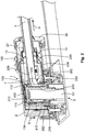
- an electrical contact device 53 ( Fig. 2 ), configured as a pin or tab contact device 53 of the mating connector 5, can be or is plugged into the contact device 300.
- a contact device assembly 10 (see Figs. 3 to 5 ) comprises, as a housing 100, 200, an upper housing 100 and a lower housing 200 which, in this case, are configured as housing shells 100, 200.
- the two housing shells 100, 200 constitute a contact chamber 130, 230 in which a contact section 310 (bushing 310) of the bushing contact device 300 can be received or is received.
- a remaining section (crimping section 320) of the contact device 300 can be received or is received in a second cavity of the assembly 10. This cavity is in this case obviously connected to the contact chamber 130, 230, in terms of being connected in a fluid-mechanical manner.
- the housing 100, 200 of the contact device assembly 10 is surrounded by a shield 190, 290 which comprises an upper shielding casing 190 and a lower shielding casing 290 which overlap in a circumferential direction (perpendicular to a plug-in direction S of the connector 1) around the assembly 10 at least in sections, but preferably entirely.
- the lower shielding casing 290 is open and configured with inwardly pointing shielding springs 292.
- a shield of the mating connector 5 can electrically contact at the shielding springs 292.
- the upper shielding casing 190 and the lower shielding casing 290 are electrically connectable or connected with a shield 90 of the electrical line 3.
- the contact section 310 of the bushing contact device 300 is received within the contact chamber 130, 230 of the contact device assembly 10, such that a mating contact receptacle 350 of the contact section 310 can receive the mating contact device 53.
- an electromechanical contact disc 355 with contact spring arms and/or contact spring fins 355 can be provided inside on a side wall in the mating contact receptacle 350 ( Fig. 4 , omitted in Fig. 3 ).
- the contact section 310 or bushing contact device 300 is hereby stopped in the plug-in direction S of the connector 1 in the contact chamber 130, 230, or the contact section 310 or contact device 300 is seated on the contact section 310 through a prestressing force F or the contact device 300 is seated, mechanically prestressed, in the contact chamber 130, 230.
- the following comments relate to the contact section 310 of the contact device 300, but can similarly relate to the entire contact device 300.
- This mechanical prestressing force F is exerted by a contact device stop spring 400 configured as a contact device overspring 400, onto the contact section 310 in at least one location of the contact section 310 (cf. Fig. 4 ).
- the contact section 310 is received in the overspring 400 which, for its part, is received in the contact chamber 130, 230 of the contact device assembly 10.
- the prestressing force F from the overspring 400 acts in a region between the contact section 310 and the crimping section 320 counter to the plug-in direction S of the connector 1 onto the contact device 300.
- the notch itself can in turn be configured as a spring device or a spring arm.
- the contact section 310 is in this case received in the overspring 400 such that the overspring 400 to a certain extent prevents, i.e. inhibits, a movement of the contact section 310 counter to the plug-in direction S and stops the contact section 310 in a prestressed manner in the contact chamber 130, 230.
- the overspring 400 is situated with a prestressing section configured as a prestressing edge 430, on top and on the outside between the contact section 310 and the crimping section 320.
- the contact section 310 is situated substantially opposite on the base 216 of the contact chamber 130, 230 or a base wall 216 of the lower housing 200. In other words, the contact section 310 is clamped between the prestressing edge 430 and the base 216.
- the overspring 400 Since the overspring 400 cannot be fitted sufficiently precisely into the contact chamber 130, 230 in the case of the given tolerances, the overspring 400 itself is situated mechanically prestressed in the contact chamber 130, 230, between the contact section 310 and a cover 111 of the contact chamber 130, 230 or a cover wall 111 of the upper housing 100.
- the mechanical prestressing results from a spring device 420 between a stop body 410 of the overspring 400, therefore preferably the actual overspring 400, and the cover 111 of the upper housing 100.
- the spring device 420 can be provided as an independent structural element and/or on the cover 111.
- the spring device 420 is preferably integrated in a front end wall 411 of the overspring 400 in the overspring 400.
- a preferably U-shaped through-slot 421 in the front end wall 411 cuts the spring device 420 then configured as a spring arm 422 free from the front end wall 411.
- Two such spring arms 422 are preferably configured in the front end wall 411.
- a relevant actuation projection 112 on the cover 111 of the contact chamber 130, 230 presses on the respective spring arm 422, wherein the spring arms 422 press the stop body 410 against the contact section 310, the crimping section 320 or a transition region between the contact section 310 and the crimping section 320.
- Figs. 7 and 8 show the overspring 400 employed in the present case, in two different perspective depictions.
- the overspring 400 in terms of its external shape, i.e. its clear external form omitting one or a plurality of open sides, is configured to be substantially cuboid.
- the overspring 400 is preferably stamped out of a single stamping blank and bent into shape and, starting from the front end wall 411 downwards, comprises a comparatively long longitudinal side wall 412, two transverse side walls 414, 415 and a comparatively short longitudinal side wall 413.
- the preferably two spring devices 420 are configured, situated in the inside, in the front end wall 411. In other words, in an unstressed state, the two spring devices 420 do not project inwards or outwards from the front end wall 411. In a stressed state, the two spring devices 420 protrude from the front end wall 411 inwards into the overspring 400 or the stop body 410. Furthermore, the comparatively short longitudinal side wall 413 or the free end thereof forms the prestressing section 430 or the prestressing edge 430 of the overspring 400.
- the overspring 400 preferably comprises a narrow front end wall 411 as a substantially closed side, omitting the through-slots 412, a narrow and comparatively long longitudinal side wall 412 as a substantially closed side, a narrow and comparatively short longitudinal side wall 413 as a partially open side, and the two wide transverse side walls 414, 415, as substantially closed sides.
- the overspring 400 or the stop spring 400 is preferably open, i.e. possesses an open front end 416 here.
- the contact section 310 is received in the overspring 400, with at least one projection 312, but preferably two projections 312, of the contact section 310 protruding below from the overspring 400 which is open there.
- the contact device 300 extends with its crimped section 320 out of the laterally open overspring 400 beneath the comparatively short longitudinal side wall 413, wherein this longitudinal side wall 413 is seated with its free end as a prestressing edge 430 on top of the contact section 310 and in the assembled state presses this onto the base 216.
- the contact section 310 with the overspring 400 located above it is received in the contact chamber 130, 230, wherein the actuation projections 112 on the cover 111 press the spring devices 420, the spring devices 420 for their part press the stop body 410 and the stop body 410 for its part presses, with its prestressing edge 430, the contact section 310 (and the crimped section 320) in the direction of the base 216 on which the contact section 310 rests by its projections 312 which protrude out of the overspring 400. It is obviously possible to create these projections 312 through the base wall 216.
Landscapes
- Connector Housings Or Holding Contact Members (AREA)
- Details Of Connecting Devices For Male And Female Coupling (AREA)
Abstract
Description
- The invention relates to a contact device stop spring for an electrical contact device assembly or an electrical connector, an electrical contact device assembly and/or an electrical connector, in particular an electrical plug connector, for an application in the low, medium or high voltage and/or current range, in particular for vehicles. The invention further relates to a device, a module, an appliance, an apparatus, a mechanism or a system, in particular for the motor vehicle sector.
- A large number of electrical connection devices, bushing connectors and/or pin connectors, etc. - hereafter referred to as (electrical) (mating) connectors or (mating) connection devices - which serve to transmit electrical currents, voltages, signals and/or data with a large spectrum of currents, voltages, frequencies and/or data rates are known in the electrical sector (electronics, electrical engineering, electrics, electrical energy technology, etc.). In the low, medium or high voltage and/or current range, and in particular in the motor vehicle sector, such connectors must guarantee, in the short term and/or permanently, a problem-free transmission of electrical power, signals and/or data, in warm, possibly hot, contaminated, humid and/or chemically aggressive surroundings. Due to a large spectrum of applications, a large number of specially configured connectors are known.
- Such connectors or their housing can be installed on an electrical line, a cable, a cable harness and/or an electrical device, such as e.g. on/in a housing or at/on a printed circuit board of an electrical, electro-optical or electronic component or such a power unit; in the latter case, a (mating) connector device is often spoken of. If a connector is only located on a line, a cable or a cable harness, then a (flying) (plug-in)connector or a plug or a coupling is mainly spoken of, if it is located on/in an electrical, electronic or electro-optical component, then a (mounting) connector, such as a (mounting) plug or a (mounting) bushing is mainly spoken of. Furthermore a connector to such a device is often referred to as a plug receptacle or header.
- In the case of high vibration stresses, as can arise in a vehicle, for example, there can be relative movements between the contact devices of a connector (or of a mating connector) and of a mating connector (or of a connector), e.g. a bushing contact device and a tab contact device, in an electrical plug connection. Starting from an already fixed plug housing of the connector in/on the mating connector, a movement of the contact device in a contact chamber of the connector is mainly to be prevented. Movements can be introduced into an electrical contact region between the connector and the mating connector in particular through a moved earth of a relevant electrical line.
- The problem of the invention is to reduce a movement of an electrical contact device in an electrical connector due to movements of a line which is electrically linked to this connector. In this case, an absorption of movement and thus an absorption of force in the plug-in direction of the connector or in an outgoing direction of an electrical line away from the connector or perpendicular to this is paramount. A problem of the invention is therefore to specify an electrical connector, an electrical contact device assembly for an electrical connector or a device for this. It should be possible to accomplish this taking into account a simple tool construction for manufacturing the connector or the contact device assembly.
- The problem of the invention is solved in accordance with the independent claims by means of a contact device stop spring for an electrical contact device assembly or an electrical connector, an electrical contact device assembly and an electrical connector, in particular an electrical plug connector, for an application in the low, medium or high voltage and/or current range, and a device, a module, an appliance, an apparatus, a mechanism or a system, in particular for the motor vehicle sector. Advantageous further developments, additional features and/or advantages of the invention arise from the dependent claims and the following description.
- The contact device stop spring according to the invention has a stop body and a spring device, wherein a prestressing force for the stop body can be made available by means of the spring device, and the prestressing force can be applied to a contact device of the connector in a contact chamber of the connector by means of the stop body. The stop spring can be configured such that the stop body is able to engage the contact device and the spring device can be actuated by the connector.
- As a result of this, the contact device is able to be stopped or braced, the contact device being able to be pushed by the stop spring against a wall of the contact chamber. Here, forces are compensated in a counter direction, i.e. substantially counter to a spring force from the spring device, such that the contact device cannot move in the contact chamber at least in these directions, or can do so only with comparatively large exertion of force. Forces from an electrical line can be compensated by this.
- In one exemplary embodiment, the stop body has a prestressing section, by means of which the stop body can engage at the contact device. Furthermore, in an exemplary embodiment, the spring device is arranged at/in the stop spring, such that, by means of the spring device, the prestressing force can be impressed preferably substantially perpendicularly on the prestressing section. The spring device can be configured by an in particular planar material layer of the stop spring. Furthermore, the prestressing section can be configured by an edge, in particular an outer edge, preferably a recessed outer edge of the stop spring.
- The stop body can possess a substantially cuboid, clear external form, wherein the spring device is constituted in part by a preferably narrow front end wall, and the prestressing section is constituted in part by a preferably narrow and preferably short longitudinal side wall of the stop body. In other words, the stop spring is substantially closed at one of six sides by means of the preferably narrow front end wall, and the stop spring is partially open at one side by means of the preferably short longitudinal side wall. Opposite the preferably narrow front end wall with the spring device, the stop spring is at least partially open or possesses a completely open second front end.
- Furthermore, the stop body can be constituted in part by a preferably narrow and preferably long longitudinal side wall. In other words, the stop spring is closed at one side by means of the preferably narrow longitudinal side wall. In addition, the stop body can be constituted in part by at least one preferably wide transverse side wall. In other words, the stop spring is closed at one side by means of a preferably wide transverse side wall. The stop spring preferably has two such transverse side walls. In other words, the stop spring can be configured as a sleeve-type contact device overspring.
- In an exemplary embodiment, the stop spring can be manufactured from a metal, in particular a sheet metal. The stop spring is preferably manufactured from a steel sheet, which is stamped, if necessary embossed, and curved. Other materials, including elastically deformable materials, such as a rubber or a plastic, for example, can be used. The stop spring preferably has two spring devices. A spring arm of the spring device can be configured by a through-slot in the stop body. The through-slot can be configured substantially in a U-shape and/or the spring arm can be configured substantially in an I-shape or an L-shape.
- The stop spring can be configured in one piece, materially in one piece or integrally. This also means that the stop body and the spring device can be configured in one piece, materially in one piece or integrally with one another. In this context, "in one piece" is meant to mean that the stop body and the spring device cannot be easily separated, i.e. are held together at least in a force-fitting and/or form-fitting manner. The stop body and the spring device are materially in one piece if they are configured in a firmly bonded manner, where applicable with a force-fitting and/or form-fitting manner, i.e. they cannot be separated without damage. The stop body and the spring device are configured integrally if they are configured substantially homogeneously or produced in one single piece. This can be transferred similarly to the stop spring.
- The electrical contact device assembly according to the invention or the electrical connector according to the invention comprises a housing and an electrical contact device arranged in a contact chamber of the housing, wherein the contact device is received in the contact chamber mechanically prestressed in at least one spatial direction by means of a contact device stop spring. Here, the contact device is received in the contact chamber mechanically prestressed, for example, in a plug-in direction of the connector, in a direction perpendicular to the plug-in direction of the connector, in an outgoing direction of an electrical line from the connector and/or in a direction perpendicular to the outgoing direction of the electrical line. Other directions can obviously be used.
- In an exemplary embodiment, at least one section of the stop spring can be arranged between a cover wall in the housing and the contact device. Furthermore, a free longitudinal end section (contact section) of the contact device (i.e. opposite an electrical line at the contact device) can be received in/at the stop spring. Furthermore, the stop spring can exert a prestressing force onto the contact device by a prestressing section preferably constituted by a longitudinal side wall. In addition, the contact device can protrude at one side from the stop spring which is substantially opposite that side of the contact device at which the prestressing section engages.
- The stop spring can have a spring device by means of which the prestressing force can be exerted onto the contact device. Here, the spring device is preferably configured as a spring arm cut free in a material layer of the stop spring. Here, the spring device can be actuated by an actuation projection on the cover wall. It is obviously possible to reverse this kinematically, i.e. to omit the actuation projection and provide the spring device, e.g. in turn as a spring arm, standing outwards away from the stop spring, i.e. in such a case the spring device is able to be actuated or is actuated by the cover wall.
- The contact device can be configured as a bushing contact device. Another contact device may obviously be used. The stop spring is preferably received in a mainly or substantially form-fitting manner in the contact chamber. This also means that a clear external form of the stop spring, preferably a cuboid, and a clear internal form of the contact chamber, therefore also preferably a cuboid, are substantially identical, with a volume of these two clear forms in turn being mainly or substantially identical. A plug-in direction of the stop spring onto the contact device can be arranged substantially parallel to the plug-in direction of the connector. Furthermore, a plug-in direction of the contact device into the stop spring can be arranged substantially perpendicular to the plug-in direction of the connector.
- The contact device assembly according to the invention or the electrical connector according to the invention has a contact device stop spring according to the invention. A device according to the invention, a module according to the invention, an appliance according to the invention, an apparatus according to the invention, a mechanism according to the invention or a system according to the invention has a contact device stop spring according to the invention, an electrical contact device assembly according to the invention and/or an electrical connector according to the invention.
- According to the invention, the contact device is able to be stopped or is stopped or is able to be braced or is braced in a contact chamber of the connector in order to absorb the forces from a movement which acts on the contact device (mechanical momentum). Stopping or bracing of the contact device can in this case occur in one, two or all three spatial directions. An absorption of force due to the stopping or bracing in a plug-in direction of the connector and/or perpendicular to an outgoing direction of an electrical line of the connector is preferred here. The invention can be used, for example, on a flat contact system or a round contact system with an approximately 90° and approximately 0°/180° line outgoing direction. The invention is obviously also able to be used in other contact systems.
- The invention is explained in greater detail below using exemplary embodiments with reference to the attached detailed drawings, which are not to scale. Elements, structural elements or components which possess an identical, univocal or similar configuration and/or function are characterised in the description of the figures, the list of reference numerals and the claims with the same reference numerals and with the same reference numerals in the figures (Fig.) of the drawings. Possible alternatives, static and/or kinematic inversions, combinations, etc., which are not explained in the description, which are not depicted in the drawings and/or which are not complete, regarding the explained exemplary embodiments of the invention or individual assemblies, parts or sections thereof, can be inferred from the list of reference numerals.
- All of the explained features, including those of the list of reference numerals, can be used not only in the specified combination or the specified combinations, but also in another combination or other combinations or in isolation. In particular, using the reference numerals and the associated features in the description of the invention, the description of the figures and/or the list of reference numerals, it is possible to replace a feature or a plurality of features in the description of the invention and/or the description of the figures. Furthermore, a feature or a plurality of features in the claims can be interpreted, specified in greater detail and/or substituted. In the perspective figures:
- Fig. 1
- shows a closed external view of an electrical connector according to the invention in a plugged-together state with a mating connector;
- Fig. 2
- shows a longitudinal sectional view of the connector and the mating connector from
Fig. 1 in a region of two plugged-together electrical contact devices, the connector and the mating connector; - Fig. 3
- shows an opened lower view of an electrical contact device assembly of the connector from
Fig. 1 , with the contact device inserted in an upper housing of the assembly; - Fig. 4
- shows a sectional side view of the assembly from
Fig. 3 , having two housing shells, two shielding casings, the contact device and a stop spring according to the invention over the contact device; - Fig. 5
- shows a view and depiction of the assembly similar to
Fig. 3 , wherein the assembly furthermore has a lower housing; - Fig. 6
- shows the contact device with an electrical line provided thereto and the contact device stop spring according to the invention provided over the contact device;
- Fig. 7
- shows a long-side view of the stop spring according to the invention, wherein a prestressing section of the stop spring can be seen; and
- Fig. 8
- shows a front-end view of the stop spring according to the invention, wherein spring devices of the stop spring can be seen.
- The invention (
Figs. 1 to 8 ) is explained in greater detail hereafter using exemplary embodiments of a depicted embodiment of a variant of an electrical high-voltage connector 1 or of an electrical high-voltage connector device 1 for the motor vehicle sector (electro mobility, hybrid technology, fuel cell, etc.). The invention is not restricted to such a variant and/or this embodiment, but rather is of a more fundamental nature, such that it can be applied to all connectors or connector devices or mating connectors or mating connector devices in the motor vehicle sector or a non-motor vehicle sector, such as an electrical engineering sector. - Furthermore, the names electrical connector 1 or electrical connector device 1 and
electrical mating connector 5 or electricalmating connector device 5, electricalcontact device assembly 10 and electrical connector 1,electrical contact device 300 of the connector 1 andelectrical contact device 53 of themating connector 5, electricalbushing contact device 300 and electrical tab orpin contact device 53 should be interpreted as being synonymous, i.e. as each being interchangeable with one another. - An attachment according to the invention or the connector 1 according to the invention can, for example, be configured as a straight-lined or an angled (
Fig. 1 ) electrical attachment or connector 1 for an electrical low/medium/high-voltage or current connection. This is, for example, a connector device, a plug connector, bushing connector, pin connector/tab connector or hybrid connector, a header or attachment head, a (mounting) bushing, a (mounting) plug, a bushing receptacle and/or plug receptacle, a (flying) coupling, an interface (physical), an interface, etc. Hereby, the attachment or the connector 1 is in particular that of adevice 0, which is preferably configured as an electrical, electronic, electro-optical,electromechanical device 0, e.g. as amodule 0, anappliance 0, anapparatus 0, amechanism 0, asystem 0, etc. for the motor vehicle sector or a non-motor vehicle sector, e.g. an electrical engineering sector. - The connector 1 according to the invention and an
electrical mating connector 5 are hereby configured as a plug-bushing pair. The connector 1 andmating connector 5 are complementary in their structures (e.g. housing sections, plugging or guiding sections, etc.) which are similar or correspond in regions and/or in their relevant complementary sections (e.g. electrical/electronic/optical contact sections, mechanical codings, latching devices, etc.), etc. In other words, statements regarding the connector 1 apply in a statically/kinematically concordant manner (corresponding structures or sections) or a statically/kinematically reverse manner (complementary structures or sections) to themating connector 5 and vice versa. - The connector 1 (see
Figs. 1 and2 ) possesses in itshousing 2, arranged in twocontact chambers 13, in each case one screened electrical contact device assembly 10 (Fig. 3 to 5 ). Therespective assembly 10 possesses anelectrical contact device 300 which is configured as abushing contact device 300 and to which anelectrical line 3 is affixed, in particular crimped. At the outgoing side of the line (outgoing direction A) theline 3 is sealed with respect to thehousing 2 by means of aseal 20 and thehousing 2 is closed by means of acover 30. An electrical contact device 53 (Fig. 2 ), configured as a pin ortab contact device 53 of themating connector 5, can be or is plugged into thecontact device 300. - A contact device assembly 10 (see
Figs. 3 to 5 ) comprises, as ahousing upper housing 100 and alower housing 200 which, in this case, are configured ashousing shells Fig. 4 ) the twohousing shells contact chamber bushing contact device 300 can be received or is received. Aside from this, a remaining section (crimping section 320) of thecontact device 300 can be received or is received in a second cavity of theassembly 10. This cavity is in this case obviously connected to thecontact chamber - The
housing contact device assembly 10 is surrounded by ashield upper shielding casing 190 and alower shielding casing 290 which overlap in a circumferential direction (perpendicular to a plug-in direction S of the connector 1) around theassembly 10 at least in sections, but preferably entirely. In a region of thelower housing 200, thelower shielding casing 290 is open and configured with inwardly pointing shielding springs 292. In a plugged-together state of the connector 1 and the mating connector 5 a shield of themating connector 5 can electrically contact at the shielding springs 292. Furthermore, theupper shielding casing 190 and thelower shielding casing 290 are electrically connectable or connected with ashield 90 of theelectrical line 3. - The
contact section 310 of thebushing contact device 300 is received within thecontact chamber contact device assembly 10, such that amating contact receptacle 350 of thecontact section 310 can receive themating contact device 53. For good electrical contacting between thecontact device 300 and themating contact device 53, anelectromechanical contact disc 355 with contact spring arms and/orcontact spring fins 355 can be provided inside on a side wall in the mating contact receptacle 350 (Fig. 4 , omitted inFig. 3 ). - The
contact section 310 orbushing contact device 300 is hereby stopped in the plug-in direction S of the connector 1 in thecontact chamber contact section 310 orcontact device 300 is seated on thecontact section 310 through a prestressing force F or thecontact device 300 is seated, mechanically prestressed, in thecontact chamber contact section 310 of thecontact device 300, but can similarly relate to theentire contact device 300. - This mechanical prestressing force F is exerted by a contact
device stop spring 400 configured as acontact device overspring 400, onto thecontact section 310 in at least one location of the contact section 310 (cf.Fig. 4 ). In this case, thecontact section 310 is received in theoverspring 400 which, for its part, is received in thecontact chamber contact device assembly 10. In this case, theoverspring 400 with its clear outer delimitations mainly or substantially completely fills thecontact chamber overspring 400 and where applicable a gap over itsfront end wall 411 with thespring device 420 and/or over abase 216 of thecontact chamber projections 312 of thecontact section 310. - In the present case, the prestressing force F from the overspring 400 (see
Fig. 4 ) acts in a region between thecontact section 310 and the crimpingsection 320 counter to the plug-in direction S of the connector 1 onto thecontact device 300. An alternative and/or an addition position at which theoverspring 400 can engage at or in thecontact device 300, e.g. at a free end of thecontact section 310, is/are possible. In the present embodiment, it would be possible, for example with a inwardly pointing notch of theoverspring 400, to load the free end of thecontact section 310 with a prestressing force. In this case, the notch itself can in turn be configured as a spring device or a spring arm. - The
contact section 310 is in this case received in theoverspring 400 such that theoverspring 400 to a certain extent prevents, i.e. inhibits, a movement of thecontact section 310 counter to the plug-in direction S and stops thecontact section 310 in a prestressed manner in thecontact chamber overspring 400 is situated with a prestressing section configured as aprestressing edge 430, on top and on the outside between thecontact section 310 and the crimpingsection 320. Thecontact section 310 is situated substantially opposite on thebase 216 of thecontact chamber base wall 216 of thelower housing 200. In other words, thecontact section 310 is clamped between theprestressing edge 430 and thebase 216. - Since the
overspring 400 cannot be fitted sufficiently precisely into thecontact chamber overspring 400 itself is situated mechanically prestressed in thecontact chamber contact section 310 and acover 111 of thecontact chamber cover wall 111 of theupper housing 100. The mechanical prestressing results from aspring device 420 between astop body 410 of theoverspring 400, therefore preferably theactual overspring 400, and thecover 111 of theupper housing 100. Alternatively, thespring device 420 can be provided as an independent structural element and/or on thecover 111. - In the depicted embodiment, the
spring device 420 is preferably integrated in afront end wall 411 of theoverspring 400 in theoverspring 400. A preferably U-shaped through-slot 421 in thefront end wall 411 cuts thespring device 420 then configured as aspring arm 422 free from thefront end wall 411. Twosuch spring arms 422 are preferably configured in thefront end wall 411. In a mounted state, arelevant actuation projection 112 on thecover 111 of thecontact chamber respective spring arm 422, wherein thespring arms 422 press thestop body 410 against thecontact section 310, the crimpingsection 320 or a transition region between thecontact section 310 and the crimpingsection 320. -
Figs. 7 and 8 show theoverspring 400 employed in the present case, in two different perspective depictions. In this case, theoverspring 400, in terms of its external shape, i.e. its clear external form omitting one or a plurality of open sides, is configured to be substantially cuboid. Theoverspring 400 is preferably stamped out of a single stamping blank and bent into shape and, starting from thefront end wall 411 downwards, comprises a comparatively longlongitudinal side wall 412, twotransverse side walls longitudinal side wall 413. - In the
front end wall 411 of thestop body 410, the preferably twospring devices 420 are configured, situated in the inside, in thefront end wall 411. In other words, in an unstressed state, the twospring devices 420 do not project inwards or outwards from thefront end wall 411. In a stressed state, the twospring devices 420 protrude from thefront end wall 411 inwards into theoverspring 400 or thestop body 410. Furthermore, the comparatively shortlongitudinal side wall 413 or the free end thereof forms theprestressing section 430 or theprestressing edge 430 of theoverspring 400. - The
overspring 400 preferably comprises a narrowfront end wall 411 as a substantially closed side, omitting the through-slots 412, a narrow and comparatively longlongitudinal side wall 412 as a substantially closed side, a narrow and comparatively shortlongitudinal side wall 413 as a partially open side, and the two widetransverse side walls front end wall 412, theoverspring 400 or thestop spring 400 is preferably open, i.e. possesses an openfront end 416 here. - In an assembled state (see
Figs. 2 and4 ), thecontact section 310 is received in theoverspring 400, with at least oneprojection 312, but preferably twoprojections 312, of thecontact section 310 protruding below from theoverspring 400 which is open there. Thecontact device 300 extends with itscrimped section 320 out of the laterallyopen overspring 400 beneath the comparatively shortlongitudinal side wall 413, wherein thislongitudinal side wall 413 is seated with its free end as aprestressing edge 430 on top of thecontact section 310 and in the assembled state presses this onto thebase 216. - The
contact section 310 with theoverspring 400 located above it is received in thecontact chamber actuation projections 112 on thecover 111 press thespring devices 420, thespring devices 420 for their part press thestop body 410 and thestop body 410 for its part presses, with itsprestressing edge 430, the contact section 310 (and the crimped section 320) in the direction of the base 216 on which thecontact section 310 rests by itsprojections 312 which protrude out of theoverspring 400. It is obviously possible to create theseprojections 312 through thebase wall 216. - It is obviously possible to transfer the invention from a
contact device assembly 10 with itscontact chamber contact chamber 13. Furthermore, it is of course possible to similarly stop or brace thecontact device 300 in thecontact chamber electrical line 3 or another direction. -
- 0.
- Device; module, appliance, apparatus, mechanism, system, etc. for the motor vehicle sector or a non-motor vehicle sector
- 1
- electrical connector [mating connector] for an electrical low/medium/high voltage or current connection, preferably for the motor vehicle or electrical engineering sector, straight-lined (e.g. approximately 0°/180°) or angled (e.g. approximately 90°): e.g. connector device [counter connector device] plug connector, bushing connector, pin connector/tab connector or hybrid connector, header or attachment head, (mounting) bushing, (mounting) plug, bushing receptacle and/or plug receptacle, (flying) coupling, interface (physical), interface, etc.
- 2
- housing, plug housing
- 3
- electrical line, electrical cable, cable harness, etc.
- 5
- electrical mating connector [connector]: mating connector device [connector device] in the region of the actual mechanical and/or electrical interface(s) or overlapping location(s) formed complementary to the connector 1
- 10
- electrical contact device assembly
- 13
- contact chamber
- 20
- seal
- 30
- cover
- 53
- electrical mating contact device, pin/tab contact device/bushing contact device
- 90
- shielding of the
electrical line 3 - 100
- housing (shell), upper housing
- 111
- cover, cover wall in the
housing 100 - 112
- actuation projection for
spring device 420 - 130
- contact chamber for
contact device 300 - 190
- upper shielding casing
- 200
- housing (shell), lower housing
- 216
- base, base wall in the
housing 200 - 230
- contact chamber for
contact device 300 - 290
- lower shielding casing
- 292
- shielding spring
- 300
- electrical contact device, bushing contact device / pin/tab contact device
- 310
- contact section, bushing/tab
- 312
- projection
- 320
- crimping section
- 350
- mating contact receptacle for receiving the
mating contact device 53 - 355
- electromechanical contact disc with contact spring arms and/or contact spring fins
- 400
- contact device stop spring, contact device overspring
- 410
- stop body
- 411
- (narrow) front end wall, substantially closed side
- 412
- (narrow, long) longitudinal side wall, substantially closed side
- 413
- (narrow, short) longitudinal side wall, substantially open side
- 414
- (wide) transverse side wall, substantially closed side
- 415
- (wide) transverse side wall, substantially closed side
- 416
- open front end
- 420
- spring device
- 421
- through-slot
- 422
- spring arm
- 430
- prestressing section, prestressing edge
- A
- outgoing direction of the
electrical line 3 - F
- prestressing force onto the
contact device 300 - S
- plug-in direction of the connector 1
Claims (12)
- A contact device stop spring (400) for an electrical contact device assembly (10) or an electrical connector (1), for an application in the low, medium or high voltage and/or current range, characterised in that
the stop spring (400) has a stop body (410) and a spring device (420), wherein a prestressing force (F) for the stop body (410) is able to be made available by means of the spring device (420), and, by means of the stop body (410), the prestressing force (F) is able to be applied to a contact device (300) of the connector (1) in a contact chamber (13; 130, 230) of the connector (1). - The contact device stop spring (400) according to the preceding claim, characterised in that the stop body (410) has a prestressing section (430), by means of which the stop body (410) is engageable at the contact device (300), and/or
the spring device (420) is arranged at/in the stop spring (400), such that, by means of the spring device (420), the prestressing force (F) can be impressed preferably substantially perpendicularly on the prestressing section (430). - The contact device stop spring (400) according to any one of the preceding claims, characterised in that the spring device (420) is configured by a material layer, which is in particular planar, of the stop spring (400), and/or
the prestressing section (430) is configured by an edge (430), in particular an outer edge (430), preferably a recessed outer edge (430) of the stop spring (400). - The contact device stop spring (400) according to any one of the preceding claims, characterised in that the stop body (410) preferably possesses a substantially box-shaped clear external form, wherein
the spring device (420) is constituted in part by a preferably narrow front end wall (411), and the prestressing section (430) is constituted in part by a preferably narrow and preferably short longitudinal side wall (413) of the stop body (410). - The contact device stop spring (400) according to any one of the preceding claims, characterised in that:• the stop spring (400) is configured as a sleeve-type contact device overspring (400);• the stop spring (400) is manufactured from a metal, in particular a sheet metal;• the stop spring (400) has two spring devices (420);• a spring arm (422) of the spring device (420) is configured by a through-slot (421) in the stop body (410) ;• the through-slot (421) is configured substantially in a U-shape;• the spring arm (422) is configured substantially in an I-shape or L-shape;• the stop body (410) is constituted in part by a preferably narrow and preferably long longitudinal side wall (412);• the stop body (410) is constituted in part by at least one preferably wide transverse side wall (414, 415); and/or• the stop spring (400) is configured in one piece, materially in one piece or integrally.
- An electrical contact device assembly (10) or electrical connector (1), in particular an electrical plug connector (1), for an application in the low, medium or high voltage and/or current range, with
a housing (100/200, 2) and an electrical contact device (300) arranged in a contact chamber (130/230, 13) of the housing (100/200, 2), characterised in that
the contact device (300) is received, mechanically prestressed in at least one spatial direction, in the contact chamber (130/230, 13) by means of a contact device stop spring (400). - The electrical contact device assembly (10) or electrical connector (1) according to the preceding claim, characterised in that
the contact device (300) is received in the contact chamber (130/230, 13) mechanically prestressed in a plug-in direction (S) of the connector (1), in a direction perpendicular to the plug-in direction (S) of the connector (1), in an outgoing direction (A) of an electrical line (3) from the connector (1) and/or in a direction perpendicular to the outgoing direction (A) of the electrical line (3). - The electrical contact device assembly (10) or electrical connector (1) according to any one of the preceding claims, characterised in that
at least one section of the stop spring (400) is arranged between a cover wall (111) in the housing (100/200, 2) and the contact device (300), and/or
a free longitudinal end section of the contact device (300) is received in/at the stop spring (400). - The electrical contact device assembly (10) or electrical connector (1) according to any one of the preceding claims, characterised in that
the stop spring (400), with a prestressing section (430) preferably constituted by a longitudinal side wall (413), exerts a prestressing force (F) onto the contact device (300), and/or
the contact device (300) protrudes at one side from the stop spring (400) which is substantially opposite that side of the contact device (300) at which the prestressing section (430) engages. - The electrical contact device assembly (10) or electrical connector (1) according to any one of the preceding claims, characterised in that
the stop spring (400) has a spring device (420), by means of which the prestressing force (F) can be exerted onto the contact device (300), wherein
the spring device (420) is actuated by an actuation projection (112) at the cover wall (111) or by the cover wall (111). - The electrical contact device assembly (10) or electrical connector (1) according to any one of the preceding claims, characterised in that• the contact device (300) is configured as a bushing contact device (300);• the stop spring (400) is received in a substantially form-fitting manner in the contact chamber (130/230, 13);• a plug-in direction of the stop spring (400) onto the contact device (300) is arranged substantially parallel to the plug-in direction (S) of the connector (1);• a plug-in direction of the contact device (300) into the stop spring (400) is arranged substantially perpendicular to the plug-in direction (S) of the connector (1); and/or• the contact device assembly (10) or electrical connector (1) has a contact device stop spring (400) according to any one of the preceding claims.
- A device, module, appliance, apparatus, mechanism or system, in particular for the motor vehicle sector, characterised in that
the device, the module, the appliance, the apparatus, the mechanism or the system has a contact device stop spring (400), an electrical contact device assembly (10) and/or an electrical connector (1) according to any one of the preceding claims.
Applications Claiming Priority (1)
| Application Number | Priority Date | Filing Date | Title |
|---|---|---|---|
| DE102015119723.5A DE102015119723A1 (en) | 2015-11-16 | 2015-11-16 | Contactor detent spring, electrical contactor assembly, and electrical connector |
Publications (1)
| Publication Number | Publication Date |
|---|---|
| EP3168938A1 true EP3168938A1 (en) | 2017-05-17 |
Family
ID=57326260
Family Applications (1)
| Application Number | Title | Priority Date | Filing Date |
|---|---|---|---|
| EP16198970.2A Pending EP3168938A1 (en) | 2015-11-16 | 2016-11-15 | Contact device stop spring, electrical contact device assembly and electrical connector |
Country Status (5)
| Country | Link |
|---|---|
| US (1) | US10658782B2 (en) |
| EP (1) | EP3168938A1 (en) |
| JP (1) | JP6824703B2 (en) |
| CN (1) | CN107039837B (en) |
| DE (1) | DE102015119723A1 (en) |
Cited By (1)
| Publication number | Priority date | Publication date | Assignee | Title |
|---|---|---|---|---|
| EP3859906A1 (en) * | 2020-01-28 | 2021-08-04 | TE Connectivity Germany GmbH | Shielding spring shell for high current plug-in connections |
Families Citing this family (4)
| Publication number | Priority date | Publication date | Assignee | Title |
|---|---|---|---|---|
| DE102016221351A1 (en) * | 2016-10-28 | 2018-05-03 | Te Connectivity Germany Gmbh | Flat contact socket with extension arm |
| US11262349B2 (en) | 2017-10-11 | 2022-03-01 | Cleveland State University | Multiplexed immune cell assays on a micropillar/microwell chip platform |
| JP6730353B2 (en) * | 2018-03-20 | 2020-07-29 | 矢崎総業株式会社 | connector |
| DE102021102778A1 (en) * | 2021-02-05 | 2022-08-11 | Te Connectivity Germany Gmbh | Shield spring contact, connector with a shield spring contact and connector system with a shield spring contact |
Citations (3)
| Publication number | Priority date | Publication date | Assignee | Title |
|---|---|---|---|---|
| DE1908251U (en) * | 1964-04-23 | 1965-01-14 | Siemens Ag | OVER SPRING FOR SPRING CONNECTING PARTS. |
| WO2010057096A1 (en) * | 2008-11-17 | 2010-05-20 | J.S.T. Corporation | Female terminal assembly |
| US20150011127A1 (en) * | 2013-07-08 | 2015-01-08 | Hung Viet Ngo | Electrical connector |
Family Cites Families (11)
| Publication number | Priority date | Publication date | Assignee | Title |
|---|---|---|---|---|
| DE8410904U1 (en) * | 1984-04-06 | 1986-01-16 | Grote & Hartmann Gmbh & Co Kg, 5600 Wuppertal | Electrical connector |
| DE4312641C2 (en) * | 1993-04-19 | 1995-10-12 | Grote & Hartmann | Electrical contact sleeve |
| US5431576A (en) * | 1994-07-14 | 1995-07-11 | Elcon Products International | Electrical power connector |
| FR2730864B3 (en) * | 1995-02-17 | 1997-04-30 | Amp France | ONE-PIECE ELECTRIC FEMALE TERMINAL |
| FR2784507B1 (en) * | 1998-10-09 | 2001-01-05 | Peugeot | ELECTRICAL CONNECTION ASSEMBLY ALLOWING THE ENGAGEMENT OF CONTACT GAMES BEFORE THE ENGAGEMENT OF OTHER CONTACT GAMES |
| JP2002015809A (en) * | 2000-06-30 | 2002-01-18 | Yazaki Corp | ID connector |
| DE10248977A1 (en) * | 2002-10-21 | 2004-06-03 | Siemens Ag | Connection terminal piece for electro-motor e.g. for motor vehicle, includes molded part forming pre-mountable structural unit with carbon brushes guide |
| EP2413435B1 (en) * | 2009-03-25 | 2018-05-16 | Yazaki Corporation | Connector |
| JP5303378B2 (en) * | 2009-06-26 | 2013-10-02 | 矢崎総業株式会社 | Standby connector |
| JP5999440B2 (en) * | 2013-04-04 | 2016-09-28 | 株式会社オートネットワーク技術研究所 | connector |
| JP5604575B1 (en) * | 2013-09-25 | 2014-10-08 | イリソ電子工業株式会社 | Wire conductor connection terminal |
-
2015
- 2015-11-16 DE DE102015119723.5A patent/DE102015119723A1/en not_active Ceased
-
2016
- 2016-11-15 JP JP2016222108A patent/JP6824703B2/en active Active
- 2016-11-15 EP EP16198970.2A patent/EP3168938A1/en active Pending
- 2016-11-16 CN CN201611010185.XA patent/CN107039837B/en active Active
- 2016-11-16 US US15/353,217 patent/US10658782B2/en active Active
Patent Citations (3)
| Publication number | Priority date | Publication date | Assignee | Title |
|---|---|---|---|---|
| DE1908251U (en) * | 1964-04-23 | 1965-01-14 | Siemens Ag | OVER SPRING FOR SPRING CONNECTING PARTS. |
| WO2010057096A1 (en) * | 2008-11-17 | 2010-05-20 | J.S.T. Corporation | Female terminal assembly |
| US20150011127A1 (en) * | 2013-07-08 | 2015-01-08 | Hung Viet Ngo | Electrical connector |
Cited By (4)
| Publication number | Priority date | Publication date | Assignee | Title |
|---|---|---|---|---|
| EP3859906A1 (en) * | 2020-01-28 | 2021-08-04 | TE Connectivity Germany GmbH | Shielding spring shell for high current plug-in connections |
| KR20210096573A (en) * | 2020-01-28 | 2021-08-05 | 티이 커넥티버티 저머니 게엠베하 | Shielding spring shell for high current plug-in connections |
| CN113258377A (en) * | 2020-01-28 | 2021-08-13 | 泰连德国有限公司 | Shielding spring shell for high-current plug-in connection |
| US11710932B2 (en) | 2020-01-28 | 2023-07-25 | Te Connectivity Germany Gmbh | Shielding spring shell for high current plug-in connections |
Also Published As
| Publication number | Publication date |
|---|---|
| CN107039837A (en) | 2017-08-11 |
| CN107039837B (en) | 2021-06-04 |
| DE102015119723A1 (en) | 2017-05-18 |
| JP6824703B2 (en) | 2021-02-03 |
| JP2017098242A (en) | 2017-06-01 |
| US10658782B2 (en) | 2020-05-19 |
| US20170141503A1 (en) | 2017-05-18 |
Similar Documents
| Publication | Publication Date | Title |
|---|---|---|
| JP5876510B2 (en) | Electrical connector and connector system | |
| JP6554509B2 (en) | Connector connection structure | |
| CN102341969B (en) | Adapter | |
| JP5990376B2 (en) | Power supply unit partially filled with compound and manufacturing method thereof | |
| JP5051640B2 (en) | Electronics | |
| JP6527909B2 (en) | Connector installation structure and terminal block | |
| US8435065B2 (en) | Plug-in unit | |
| JP6448124B2 (en) | Connector device including socket-type housing, connector, and cable support | |
| CN107039837B (en) | Contact assembly retaining spring, electrical contact assembly assembly and electrical connector | |
| WO2013051075A1 (en) | Electronic circuit unit capable of external connection | |
| CN107204535B (en) | Connector device for waterproof connector, and assembled cable | |
| KR102856867B1 (en) | Vibration-proof electrical high-current flat socket contact device | |
| EP3985801A1 (en) | Electric terminal | |
| JP2008235189A (en) | Connector housing | |
| CN104254468A (en) | Electrohydraulic pressure control device for vehicle brake systems | |
| JP5999440B2 (en) | connector | |
| KR20170079582A (en) | Power distributing apparatus and assembling method | |
| KR20190032154A (en) | A connector for the module | |
| JP5794292B2 (en) | Electrical connector | |
| JP6160303B2 (en) | Switch unit | |
| JP2013214471A (en) | Card unit and card edge connector | |
| JP6037850B2 (en) | Grommet | |
| CN106030924B (en) | Connection devices between electrical or electronic appliances and plug-in connection units and uses of the connection devices | |
| JP6499142B2 (en) | Connection device | |
| CN107069316B (en) | electrical connection element |
Legal Events
| Date | Code | Title | Description |
|---|---|---|---|
| PUAI | Public reference made under article 153(3) epc to a published international application that has entered the european phase |
Free format text: ORIGINAL CODE: 0009012 |
|
| STAA | Information on the status of an ep patent application or granted ep patent |
Free format text: STATUS: THE APPLICATION HAS BEEN PUBLISHED |
|
| AK | Designated contracting states |
Kind code of ref document: A1 Designated state(s): AL AT BE BG CH CY CZ DE DK EE ES FI FR GB GR HR HU IE IS IT LI LT LU LV MC MK MT NL NO PL PT RO RS SE SI SK SM TR |
|
| AX | Request for extension of the european patent |
Extension state: BA ME |
|
| STAA | Information on the status of an ep patent application or granted ep patent |
Free format text: STATUS: REQUEST FOR EXAMINATION WAS MADE |
|
| 17P | Request for examination filed |
Effective date: 20171114 |
|
| RBV | Designated contracting states (corrected) |
Designated state(s): AL AT BE BG CH CY CZ DE DK EE ES FI FR GB GR HR HU IE IS IT LI LT LU LV MC MK MT NL NO PL PT RO RS SE SI SK SM TR |
|
| STAA | Information on the status of an ep patent application or granted ep patent |
Free format text: STATUS: EXAMINATION IS IN PROGRESS |
|
| 17Q | First examination report despatched |
Effective date: 20190423 |