EP3168669A1 - Endoscope objective optical system - Google Patents
Endoscope objective optical system Download PDFInfo
- Publication number
- EP3168669A1 EP3168669A1 EP15818866.4A EP15818866A EP3168669A1 EP 3168669 A1 EP3168669 A1 EP 3168669A1 EP 15818866 A EP15818866 A EP 15818866A EP 3168669 A1 EP3168669 A1 EP 3168669A1
- Authority
- EP
- European Patent Office
- Prior art keywords
- lens
- optical system
- lens group
- objective optical
- fob
- Prior art date
- Legal status (The legal status is an assumption and is not a legal conclusion. Google has not performed a legal analysis and makes no representation as to the accuracy of the status listed.)
- Withdrawn
Links
Images




Classifications
-
- A—HUMAN NECESSITIES
- A61—MEDICAL OR VETERINARY SCIENCE; HYGIENE
- A61B—DIAGNOSIS; SURGERY; IDENTIFICATION
- A61B1/00—Instruments for performing medical examinations of the interior of cavities or tubes of the body by visual or photographical inspection, e.g. endoscopes; Illuminating arrangements therefor
- A61B1/00163—Optical arrangements
- A61B1/00193—Optical arrangements adapted for stereoscopic vision
-
- A—HUMAN NECESSITIES
- A61—MEDICAL OR VETERINARY SCIENCE; HYGIENE
- A61B—DIAGNOSIS; SURGERY; IDENTIFICATION
- A61B1/00—Instruments for performing medical examinations of the interior of cavities or tubes of the body by visual or photographical inspection, e.g. endoscopes; Illuminating arrangements therefor
- A61B1/00064—Constructional details of the endoscope body
- A61B1/00071—Insertion part of the endoscope body
- A61B1/0008—Insertion part of the endoscope body characterised by distal tip features
- A61B1/00096—Optical elements
-
- G—PHYSICS
- G02—OPTICS
- G02B—OPTICAL ELEMENTS, SYSTEMS OR APPARATUS
- G02B13/00—Optical objectives specially designed for the purposes specified below
- G02B13/04—Reversed telephoto objectives
-
- G—PHYSICS
- G02—OPTICS
- G02B—OPTICAL ELEMENTS, SYSTEMS OR APPARATUS
- G02B23/00—Telescopes, e.g. binoculars; Periscopes; Instruments for viewing the inside of hollow bodies; Viewfinders; Optical aiming or sighting devices
- G02B23/24—Instruments or systems for viewing the inside of hollow bodies, e.g. fibrescopes
- G02B23/2407—Optical details
-
- G—PHYSICS
- G02—OPTICS
- G02B—OPTICAL ELEMENTS, SYSTEMS OR APPARATUS
- G02B23/00—Telescopes, e.g. binoculars; Periscopes; Instruments for viewing the inside of hollow bodies; Viewfinders; Optical aiming or sighting devices
- G02B23/24—Instruments or systems for viewing the inside of hollow bodies, e.g. fibrescopes
- G02B23/2407—Optical details
- G02B23/2415—Stereoscopic endoscopes
-
- G—PHYSICS
- G02—OPTICS
- G02B—OPTICAL ELEMENTS, SYSTEMS OR APPARATUS
- G02B23/00—Telescopes, e.g. binoculars; Periscopes; Instruments for viewing the inside of hollow bodies; Viewfinders; Optical aiming or sighting devices
- G02B23/24—Instruments or systems for viewing the inside of hollow bodies, e.g. fibrescopes
- G02B23/2407—Optical details
- G02B23/2423—Optical details of the distal end
- G02B23/243—Objectives for endoscopes
-
- G—PHYSICS
- G02—OPTICS
- G02B—OPTICAL ELEMENTS, SYSTEMS OR APPARATUS
- G02B23/00—Telescopes, e.g. binoculars; Periscopes; Instruments for viewing the inside of hollow bodies; Viewfinders; Optical aiming or sighting devices
- G02B23/24—Instruments or systems for viewing the inside of hollow bodies, e.g. fibrescopes
- G02B23/26—Instruments or systems for viewing the inside of hollow bodies, e.g. fibrescopes using light guides
Definitions
- the present invention relates to an objective optical system, and relates, in particular, to an endoscope objective optical system employed in a medical endoscope.
- Patent Literature 1 discloses an objective optical system provided with, sequentially from the object side, a front-group optical system shared between the left and right (in two directions of parallax) and a pair of, that is, left and right, imaging optical systems.
- the present invention has been conceived in light of the above-described circumstances, and an object thereof is to provide a small endoscope objective optical system that allows stereoscopic viewing even though a wide angle is used, that reduces the F-number, and that reduces vignetting.
- the present invention provides the following solutions.
- An aspect of the present invention provides an endoscope objective optical system that consists of, sequentially from the object side, a negative first lens group, a positive second lens group, and a pair of third lens groups that are disposed side-by-side in a direction of parallax and that form two optical images with parallax, wherein aperture stops are individually provided in the third lens groups, and conditional expression (1) below is satisfied: Fob_n / Fob_p > ⁇ 0.5 where Fob_n is a focal length of the first lens group, and Fob_p is a focal length of the second lens group.
- conditional expression (1) defines conditions related to a ratio between the focal length of the first lens group and the focal length of the second lens group, and, by decreasing the focal length of the first lens group, it is possible to form a wide-angle objective optical system in which the total angle is equal to or greater than 90°.
- conditional expression (1) defines conditions related to a ratio between the focal length of the first lens group and the focal length of the second lens group, and, by decreasing the focal length of the first lens group, it is possible to form a wide-angle objective optical system in which the total angle is equal to or greater than 90°.
- by individually providing the aperture stops in the third lens groups because it is possible to reduce the beam-bundle diameters in the third lens groups, it is possible to achieve stereoscopic viewing even though a wide angle is used, and it is possible to reduce the F-number and also to reduce vignetting.
- conditional expression (2) fs / fb ⁇ 2.5 where fs is a distance from a position of the aperture stop to an imaging surface, and fb is a distance from a final lens to the imaging surface.
- reflection optical systems having two reflection surfaces be individually disposed between the third lens groups and the imaging surface.
- conditional expression (3) fb / ihy > 4 where fb is a distance from a final lens to an imaging surface, and ihy is a maximum image height in the direction of parallax.
- the present invention affords an advantage in that it is possible to provide a small endoscope objective optical system that allows stereoscopic viewing even though a wide angle is used, that reduces the F-number, and that also reduces vignetting.
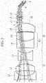
- Fig. 1 shows a cross-sectional view showing the overall configuration of the endoscope objective optical system.
- the endoscope objective optical system is provided with a plurality of lens groups sequentially from the object side, namely, a negative first lens group G1, a positive second lens group G2, and a pair of third lens groups G3 that are disposed side-by-side in a direction of parallax and that form two optical images with parallax.
- a negative first lens group G1 a positive second lens group G2
- a pair of third lens groups G3 that are disposed side-by-side in a direction of parallax and that form two optical images with parallax.
- the first lens group is provided with, sequentially from the object side, a first lens L1, a second lens L2, and a third lens L3, and has negative optical power as a whole.
- the second lens group G2 consists of, sequentially from the object side, a cemented lens CL1, formed between a fourth lens L4 and a fifth lens L5, and a sixth lens L6, and has positive optical power as a whole.
- the third lens groups G3 are disposed side-by-side in the direction of parallax, individually focus light entering from the imaging subject via the first lens group G1 and the second lens group G2, and make the focused light incident on a light-receiving surface A of an image-acquisition element.
- Each of the third lens groups G3 consists of, sequentially from the object side, a seventh lens L7, an aperture stop S, an eighth lens L8, and a ninth lens L9. In Fig. 1 , only one of the two third lens groups G3 is shown, and the other is omitted from the illustration.
- the endoscope objective optical system is configured so as to satisfy the following conditional expression (1): Fob_n / Fob_p > ⁇ 0.5 where Fob_n is the focal length of the first lens group G1, and Fob_p is the focal length of the second lens group G2.
- Conditional expression (1) defines conditions related to a ratio between the focal length of the first lens group G1 and the focal length of the second lens group G2, and, by decreasing the focal length of the first lens group G1, it is possible to form a wide-angle endoscope objective optical system in which the total angle is equal to or greater than 90°.
- conditional expression (1) the negative power due to the first lens group G1 and the second lens group G2 is reduced. Because of this, in order to satisfy the wide-angle conditions, it is necessary to position the third lens groups G3 at positions farther away from the optical axes of the first lens group G1 and the second lens group G2 in the direction of parallax, or it is necessary to expand the beam bundles traveling from the seventh lenses L7 of the third lens groups G3 to the sixth lens L6 of the second lens group G2.
- the beam-bundle diameter at the sixth lens L6 is increased, the size of the lens system as a whole is increased, and, furthermore, it is necessary to correct aberrations at a position far away from the lens center of the second lens group G2, thus making it difficult to achieve a performance level that is compatible with the high pixel counts.
- the endoscope objective optical system is configured so as to satisfy conditional expression (2): fs / fb ⁇ 2.5 where fs is the distance from the position of the aperture stop S to the imaging surface (light-receiving surface A), and fb is the distance from the ninth lens L9, which is the final lens, to the imaging surface.
- Conditional expression (2) defines the range within which the aperture stops S are positioned, and, it is possible to further reduce the beam-bundle diameters by disposing the aperture stops S within the range of conditional expression (2).
- conditional expression (2) because the distances from the aperture stops S to the imaging surface are increased, the beam-bundle diameters end up becoming large in the eighth lenses L8 and the ninth lenses L9 of the third lens groups G3. Therefore, in the third lens groups G3, vignetting occurs in the beam bundles, and thus, it becomes difficult to make the optical system compatible with a high pixel count.
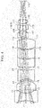
- an endoscope objective optical system consists of, sequentially from the object side, the negative first lens group G1, the positive second lens group G2, the pair of third lens groups G3 that are disposed side-by-side in the direction of parallax and that form two optical images with parallax, and reflection optical systems P having two reflection surfaces.
- the reflection optical systems P are provided between the third lens groups G3 and the imaging surface A.
- the aperture stops S are disposed on the object side of the seventh lenses L7, which are the lenses that are closest to the object side in the third lens groups G3.
- the endoscope objective optical system according to this embodiment is configured so as to satisfy conditional expression (3) below, in addition to the above-described conditional expressions (1) and (2): fb / ihy > 4 where fb is the distance from the ninth lens L9, which is the final lens, to the imaging surface A, and ihy is the maximum image height in the direction of parallax.
- the reflection optical systems P having the two reflection surfaces it is possible to form two optical images with parallax on a single image-acquisition element so as to be closer to each other, and, by satisfying conditional expression (3), it is possible to prevent the occurrence of vignetting in the beam bundles in the reflection optical systems P.
- r is the radius of curvature (unit: mm)
- d is the surface interval (mm)
- Ne is the refractive index with respect to the e-line
- ⁇ d is the Abbe number with respect to the d-line.
- Fig. 3 is a cross-sectional view showing the overall configuration of an endoscope objective optical system according to an Example of the first embodiment.
- the endoscope objective optical system according to Example 1 consists of, sequentially from the object side, a negative first lens group, a positive second lens group, and a pair of third lens groups that are arranged in the direction of parallax.
- the aperture stops S are disposed on the image-surface sides of lenses disposed closest to the object sides of the third lens groups.
- Lens data of the endoscope objective optical system according to this Example 1 are shown below.
- LENS DATA Surface Number r d Ne ⁇ d Object Surface 15 1 -3.80837 1.5 1.883 40.7645 2 4.14645 0.400822 3 -9.69475 1.50498 1.76182 26.5174 4 -2.85208 0.288 5 -3.27565 1.50498 1.63854 55.3792 6 6.22293 0.226368 7 6.83208 1.41587 1.84666 23.7775 8 6.75522 1.46717 1.7495 35.3319 9 3.18333 0.214991 10 3.73937 1.72575 1.603 65.4427 11 -3.71946 0.392832 12 -1.7681 1.04509 1.54072 47.2264 13 -2.48904 0.209019 14 (Aperture stop) 0.298598 15 2.5571 0.895795 1.92286 18.8966 16 1.45226 0.298598 17 1.98468 0.82944 1.62041 60.28
- Focal length Fob_p of the second lens group 5.60043 mm
- Distance fs from the imaging surface to the aperture stop 5.8256 mm
- Fig. 4 is a cross-sectional view showing the overall configuration of an endoscope objective optical system according to another Example of the first embodiment.
- the endoscope objective optical system according to this Example consists of, sequentially from the object side, a negative first lens group, a positive second lens group, and a pair of third lens groups that are arranged in the direction of parallax.
- the aperture stops S are disposed at the object sides of lenses disposed closest to the image-surface sides of the third lens groups.
- Lens data of the endoscope objective optical system according to this Example 2 are shown below.
- LENS DATA Surface Number r d Ne ⁇ d Object Surface 15 1 -6.95702 1.5 1.883 40.7645 2 2.98074 0.689341 3 -11.5723 1.7935 1.76182 26.5174 4 -2.83423 0.288 5 -2.74912 1.7935 1.63854 55.3792 6 11.0428 0.514887 7 10.0787 1.70439 1.84666 23.7775 8 7.26287 1.75569 1.7495 35.3319 9 4.59815 0.214991 10 5.33836 2.01427 1.603 65.4427 11 -4.52516 0.392832 12 -1.47378 1.04509 1.54072 47.2264 13 -2 0.209019 14 2.70984 0.895795 1.92286 18.8966 15 1.49409 0.298598 16 (Aperture stop) 0.1 17 2.19475 0.82944 1.62041 60.2887 18
- Fig. 5 is a cross-sectional view showing the overall configuration of an endoscope objective optical system according to an Example of the second embodiment.
- the endoscope objective optical system according to this Example consists of, sequentially from the object side, a negative first lens group, a positive second lens group, a pair of third lens groups that are arranged in the direction of parallax, and reflection optical systems having two reflection surfaces.
- the aperture stops S are disposed at the object sides of lenses disposed closest to the object sides of the third lens groups.
- Lens data of the endoscope objective optical system according to this Example 3 are shown bellow.
- LENS DATA Surface Number r d Ne ⁇ d Object Surface 15 1 -12.5697 0.6 1.883 40.7645 2 3.12377 1.04167 3 -15.47 1.36097 1.92286 18.8966 4 -3.84137 0.801512 5 -4.20218 1.36097 1.63854 55.3792 6 2.89504 1.00414 7 -19.4523 1.33611 1.84666 23.7775 8 4.08815 1.78599 1.7495 35.3319 9 -11.1098 0.1 10 -14.0755 1.6083 1.603 65.4427 11 -3.71871 0.12 12 (Aperture stop) 0.1 13 -1.00081 0.35 1.78472 25.683 14 -1.19388 0.17 15 1.59833 0.4 1.92286 18.8966 16 1.05853 0.05 17 1.22734 1.08349 1.51633 64.1411 18 -2.30257 0.9
- Fig. 6 is a cross-sectional view showing the overall configuration of an endoscope objective optical system according to another Example of the second embodiment.
- the endoscope objective optical system according to this Example consists of, sequentially from the object side, a negative first lens group, a positive second lens group, and a pair of third lens groups that are arranged in the direction of parallax, and reflection optical systems having two reflection surfaces.
- the aperture stops S are disposed at the image-surface sides of lenses disposed closest to the object sides of the third lens groups.
- Lens data of the endoscope objective optical system according to this Example 4 are shown below.
- LENS DATA Surface Number r d Ne ⁇ d Object Surface 15 1 -8.92789 0.864 1.883 40.7645 2 2.72124 0.953406 3 -3.02092 1.64979 1.92286 18.8966 4 -2.99104 0.844168 5 -2.80703 1.64979 1.63854 55.3792 6 -15.6192 1.13595 7 6.11084 1.61398 1.84666 23.7775 8 3.56736 1.79002 1.7495 35.3319 9 4.60374 0.2 10 5.72221 2.00594 1.603 65.4427 11 -6.89945 0.17 12 -1.50531 0.504 1.78472 25.683 13 -1.77592 0.1008 14 (Aperture stop) 0.144 15 1.51588 0.576 1.92286 18.8966 16 0.903019 0.1 17 1.06837 1.25022 1.51633 64.1411 18 -
- Table 1 shows values related to the above-described conditional expressions (1) to (3) in the above-described Examples 1 to 4. ⁇ Table 1 ⁇ Example 1 Example 2 Example 3 Example 4 Conditional expression (1) Fob n/Fob p > -0.5 -0.25473044 -0.227308577 -0.196863948 -0.211482323 Conditional expression (2) fs/fb ⁇ 2.5 1.662955257 1.252018037 1.714257001 1.768053184 Conditional expression (3) fb/ihy > 4 7.784802222 8.195533333 10.05001 7.701174286
Landscapes
- Physics & Mathematics (AREA)
- Health & Medical Sciences (AREA)
- Optics & Photonics (AREA)
- Life Sciences & Earth Sciences (AREA)
- Surgery (AREA)
- General Physics & Mathematics (AREA)
- Astronomy & Astrophysics (AREA)
- General Health & Medical Sciences (AREA)
- Radiology & Medical Imaging (AREA)
- Medical Informatics (AREA)
- Animal Behavior & Ethology (AREA)
- Engineering & Computer Science (AREA)
- Biomedical Technology (AREA)
- Heart & Thoracic Surgery (AREA)
- Pathology (AREA)
- Molecular Biology (AREA)
- Nuclear Medicine, Radiotherapy & Molecular Imaging (AREA)
- Biophysics (AREA)
- Public Health (AREA)
- Veterinary Medicine (AREA)
- Lenses (AREA)
- Instruments For Viewing The Inside Of Hollow Bodies (AREA)
- Endoscopes (AREA)
Abstract
Description
- The present invention relates to an objective optical system, and relates, in particular, to an endoscope objective optical system employed in a medical endoscope.
- In the related art, objective optical systems for performing stereoscopic viewing by forming two optical images with parallax on a single image-acquisition element have been proposed.
- As an example of such an objective optical system, Patent Literature 1 discloses an objective optical system provided with, sequentially from the object side, a front-group optical system shared between the left and right (in two directions of parallax) and a pair of, that is, left and right, imaging optical systems.
- {PTL 1} Japanese Unexamined Patent Application, Publication No.
Hei 8-82766 - With objective optical systems that allow wide-angle stereoscopic viewing, there has been a demand for size reduction of the objective optical systems as a whole, and thus, it is necessary to form two optical images with parallax on a single image-acquisition element so as to be closer to each other. In addition, when applying this type of objective optical system to an endoscope having a high pixel count, it is necessary to reduce the F-number to achieve greater brightness because the pitch interval of the image-acquisition element is decreased.
- However, with the objective optical system of Patent Literature 1, the pair of, that is, left and right, imaging optical systems in the subsequent stage are disposed side-by-side, and thus, the lens diameters are increased when the F-number is reduced in order to realize a higher pixel count. Therefore, in order to eliminate vignetting in a beam bundle and to prevent a reduction in resolution, it becomes necessary to increase the spacing between the two imaging optical systems. All of the above-described situations do not allow the size-reduction requirement to be fulfilled.
- The present invention has been conceived in light of the above-described circumstances, and an object thereof is to provide a small endoscope objective optical system that allows stereoscopic viewing even though a wide angle is used, that reduces the F-number, and that reduces vignetting.
- In order to achieve the above-described object, the present invention provides the following solutions.
- An aspect of the present invention provides an endoscope objective optical system that consists of, sequentially from the object side, a negative first lens group, a positive second lens group, and a pair of third lens groups that are disposed side-by-side in a direction of parallax and that form two optical images with parallax, wherein aperture stops are individually provided in the third lens groups, and conditional expression (1) below is satisfied:

- In this aspect, conditional expression (1) defines conditions related to a ratio between the focal length of the first lens group and the focal length of the second lens group, and, by decreasing the focal length of the first lens group, it is possible to form a wide-angle objective optical system in which the total angle is equal to or greater than 90°. In addition, by individually providing the aperture stops in the third lens groups, because it is possible to reduce the beam-bundle diameters in the third lens groups, it is possible to achieve stereoscopic viewing even though a wide angle is used, and it is possible to reduce the F-number and also to reduce vignetting.
- In the above-described aspect, it is preferable that conditional expression (2) below be satisfied:

- By setting the position of the aperture stop within the range of conditional expression (2) in this way, it is possible to further reduce the beam-bundle diameter.
- In addition, in the above-described aspect, it is preferable that reflection optical systems having two reflection surfaces be individually disposed between the third lens groups and the imaging surface.
- By employing the reflection optical systems having the two reflection surfaces in this way, it becomes possible to form two optical images with parallax on a single image-acquisition element so as to be closer to each other.
- In addition, in the above-described aspect, it is preferable that conditional expression (3) below be satisfied:

- By doing so, it is possible to prevent the occurrence of vignetting in beam bundles in the reflection optical systems.
- The present invention affords an advantage in that it is possible to provide a small endoscope objective optical system that allows stereoscopic viewing even though a wide angle is used, that reduces the F-number, and that also reduces vignetting.
-
- {
Fig. 1} Fig. 1 is a cross-sectional view showing the overall configuration of an endoscope objective optical system according to a first embodiment of the present invention. - {
Fig. 2} Fig. 2 is a cross-sectional view showing the overall configuration of an endoscope objective optical system according to a second embodiment of the present invention. - {
Fig. 3} Fig. 3 is a cross-sectional view showing the overall configuration of an endoscope objective optical system according to an example of the first embodiment of the present invention. - {
Fig. 4} Fig. 4 is a cross-sectional view showing the overall configuration of an endoscope objective optical system according to another example of the first embodiment of the present invention. - {
Fig. 5} Fig. 5 is a cross-sectional view showing the overall configuration of an endoscope objective optical system according to an example of the second embodiment of the present invention. - {
Fig. 6} Fig. 6 is a cross-sectional view showing the overall configuration of an endoscope objective optical system according to another example of the second embodiment of the present invention. - An endoscope objective optical system according to a first embodiment of the present invention will be described below with reference to the drawings.
-
Fig. 1 shows a cross-sectional view showing the overall configuration of the endoscope objective optical system. As shown inFig. 1 , the endoscope objective optical system is provided with a plurality of lens groups sequentially from the object side, namely, a negative first lens group G1, a positive second lens group G2, and a pair of third lens groups G3 that are disposed side-by-side in a direction of parallax and that form two optical images with parallax. Note that, in this embodiment, only one of the pair of optical systems of the third lens groups G3 disposed in the direction of parallax is illustrated for the sake of convenience of explanation. - The first lens group is provided with, sequentially from the object side, a first lens L1, a second lens L2, and a third lens L3, and has negative optical power as a whole.
- The second lens group G2 consists of, sequentially from the object side, a cemented lens CL1, formed between a fourth lens L4 and a fifth lens L5, and a sixth lens L6, and has positive optical power as a whole.
- The third lens groups G3 are disposed side-by-side in the direction of parallax, individually focus light entering from the imaging subject via the first lens group G1 and the second lens group G2, and make the focused light incident on a light-receiving surface A of an image-acquisition element. Each of the third lens groups G3 consists of, sequentially from the object side, a seventh lens L7, an aperture stop S, an eighth lens L8, and a ninth lens L9. In
Fig. 1 , only one of the two third lens groups G3 is shown, and the other is omitted from the illustration. - In addition, the endoscope objective optical system according to this embodiment is configured so as to satisfy the following conditional expression (1):

- Conditional expression (1) defines conditions related to a ratio between the focal length of the first lens group G1 and the focal length of the second lens group G2, and, by decreasing the focal length of the first lens group G1, it is possible to form a wide-angle endoscope objective optical system in which the total angle is equal to or greater than 90°. In addition, by individually providing the aperture stops in the third lens groups G3, it is possible to reduce the beam-bundle diameters in the third lens groups G3, and thus, it is possible to achieve stereoscopic viewing even though a wide angle is used, and it is possible to reduce the F-number and also to reduce vignetting.
- In the case in which conditional expression (1) is not satisfied, the negative power due to the first lens group G1 and the second lens group G2 is reduced. Because of this, in order to satisfy the wide-angle conditions, it is necessary to position the third lens groups G3 at positions farther away from the optical axes of the first lens group G1 and the second lens group G2 in the direction of parallax, or it is necessary to expand the beam bundles traveling from the seventh lenses L7 of the third lens groups G3 to the sixth lens L6 of the second lens group G2. However, because in both cases, the beam-bundle diameter at the sixth lens L6 is increased, the size of the lens system as a whole is increased, and, furthermore, it is necessary to correct aberrations at a position far away from the lens center of the second lens group G2, thus making it difficult to achieve a performance level that is compatible with the high pixel counts.
- In addition, the endoscope objective optical system is configured so as to satisfy conditional expression (2):

- Conditional expression (2) defines the range within which the aperture stops S are positioned, and, it is possible to further reduce the beam-bundle diameters by disposing the aperture stops S within the range of conditional expression (2).
- In the case in which conditional expression (2) is not satisfied, because the distances from the aperture stops S to the imaging surface are increased, the beam-bundle diameters end up becoming large in the eighth lenses L8 and the ninth lenses L9 of the third lens groups G3. Therefore, in the third lens groups G3, vignetting occurs in the beam bundles, and thus, it becomes difficult to make the optical system compatible with a high pixel count.
- As has been described, with this embodiment, it is possible to form a wide-angle endoscope objective optical system in which the total angle is equal to or greater than 90° by decreasing the focal length of the first lens group G1; it is possible to reduce the beam-bundle diameter in each of the third lens groups G3 by disposing the aperture stop S in the predetermined area of the each of the third lens groups G3; stereoscopic viewing is possible even though a wide angle is used; and it is possible to reduce the F-number and to reduce vignetting.
- In addition, as a second embodiment of the present invention, it is possible to configure an endoscope objective optical system as follows.
- As shown in
Fig. 2 , an endoscope objective optical system according to this embodiment consists of, sequentially from the object side, the negative first lens group G1, the positive second lens group G2, the pair of third lens groups G3 that are disposed side-by-side in the direction of parallax and that form two optical images with parallax, and reflection optical systems P having two reflection surfaces. In other words, the reflection optical systems P are provided between the third lens groups G3 and the imaging surface A. In addition, in this embodiment, the aperture stops S are disposed on the object side of the seventh lenses L7, which are the lenses that are closest to the object side in the third lens groups G3. - In addition, the endoscope objective optical system according to this embodiment is configured so as to satisfy conditional expression (3) below, in addition to the above-described conditional expressions (1) and (2):

- By employing the reflection optical systems P having the two reflection surfaces, it is possible to form two optical images with parallax on a single image-acquisition element so as to be closer to each other, and, by satisfying conditional expression (3), it is possible to prevent the occurrence of vignetting in the beam bundles in the reflection optical systems P.
- Next, Examples 1 to 4 of the endoscope objective optical systems according to one of the above-described embodiments will be described with reference to
Figs. 3 to 6 . In lens data described in the Example sections, r is the radius of curvature (unit: mm), d is the surface interval (mm), Ne is the refractive index with respect to the e-line, and νd is the Abbe number with respect to the d-line. -
Fig. 3 is a cross-sectional view showing the overall configuration of an endoscope objective optical system according to an Example of the first embodiment. - The endoscope objective optical system according to Example 1 consists of, sequentially from the object side, a negative first lens group, a positive second lens group, and a pair of third lens groups that are arranged in the direction of parallax. In addition, the aperture stops S are disposed on the image-surface sides of lenses disposed closest to the object sides of the third lens groups.
- Lens data of the endoscope objective optical system according to this Example 1 are shown below.
LENS DATA Surface Number r d Ne νd Object Surface 15 1 -3.80837 1.5 1.883 40.7645 2 4.14645 0.400822 3 -9.69475 1.50498 1.76182 26.5174 4 -2.85208 0.288 5 -3.27565 1.50498 1.63854 55.3792 6 6.22293 0.226368 7 6.83208 1.41587 1.84666 23.7775 8 6.75522 1.46717 1.7495 35.3319 9 3.18333 0.214991 10 3.73937 1.72575 1.603 65.4427 11 -3.71946 0.392832 12 -1.7681 1.04509 1.54072 47.2264 13 -2.48904 0.209019 14 (Aperture stop) 0.298598 15 2.5571 0.895795 1.92286 18.8966 16 1.45226 0.298598 17 1.98468 0.82944 1.62041 60.2887 18 -3.11608 3.503161 19 (Image Surface) - Focal length Fob_n of the first lens group -1.4266 mm Focal length Fob_p of the second lens group 5.60043 mm Distance fs from the imaging surface to the aperture stop 5.8256 mm
- Distance fb from the final lens to the imaging surface 3.503161 mm
- Maximum image height ihy in the direction of parallax 0.45 mm Amounts of displacement between the optical axis of the third lens group and the optical axes of the first and second lens groups 0.72 mm
- F-number 4
- Angle of view 59.9433°
- Fob_n/Fob_p -0.25473044
- fs/fb 1.662955257
- fb/ihy 7.784802222
-
Fig. 4 is a cross-sectional view showing the overall configuration of an endoscope objective optical system according to another Example of the first embodiment. - The endoscope objective optical system according to this Example consists of, sequentially from the object side, a negative first lens group, a positive second lens group, and a pair of third lens groups that are arranged in the direction of parallax. In addition, the aperture stops S are disposed at the object sides of lenses disposed closest to the image-surface sides of the third lens groups.
- Lens data of the endoscope objective optical system according to this Example 2 are shown below.
LENS DATA Surface Number r d Ne νd Object Surface 15 1 -6.95702 1.5 1.883 40.7645 2 2.98074 0.689341 3 -11.5723 1.7935 1.76182 26.5174 4 -2.83423 0.288 5 -2.74912 1.7935 1.63854 55.3792 6 11.0428 0.514887 7 10.0787 1.70439 1.84666 23.7775 8 7.26287 1.75569 1.7495 35.3319 9 4.59815 0.214991 10 5.33836 2.01427 1.603 65.4427 11 -4.52516 0.392832 12 -1.47378 1.04509 1.54072 47.2264 13 -2 0.209019 14 2.70984 0.895795 1.92286 18.8966 15 1.49409 0.298598 16 (Aperture stop) 0.1 17 2.19475 0.82944 1.62041 60.2887 18 -2.97994 3.68799 19 (Image Surface) -
- Focal length Fob_n of the first lens group -1.61395 mm Focal length Fob_p of the second lens group 7.10026 mm Distance fs from the imaging surface to the aperture stop 4.61743 mm
- Distance fb from the final lens to the imaging surface 3.68799 mm
- Maximum image height ihy in the direction of parallax 0.45 mm Amounts of displacement between the optical axis of the third lens group and the optical axes of the first and second lens groups 0.72 mm
- F-number 3
- Angle of view 59.9961°
- Fob_n/Fob_p -0.227308577
- fs/fb 1.252018037
- fb/ihy 8.195533333
-
Fig. 5 is a cross-sectional view showing the overall configuration of an endoscope objective optical system according to an Example of the second embodiment. - The endoscope objective optical system according to this Example consists of, sequentially from the object side, a negative first lens group, a positive second lens group, a pair of third lens groups that are arranged in the direction of parallax, and reflection optical systems having two reflection surfaces. In addition, the aperture stops S are disposed at the object sides of lenses disposed closest to the object sides of the third lens groups.
- Lens data of the endoscope objective optical system according to this Example 3 are shown bellow.
LENS DATA Surface Number r d Ne νd Object Surface 15 1 -12.5697 0.6 1.883 40.7645 2 3.12377 1.04167 3 -15.47 1.36097 1.92286 18.8966 4 -3.84137 0.801512 5 -4.20218 1.36097 1.63854 55.3792 6 2.89504 1.00414 7 -19.4523 1.33611 1.84666 23.7775 8 4.08815 1.78599 1.7495 35.3319 9 -11.1098 0.1 10 -14.0755 1.6083 1.603 65.4427 11 -3.71871 0.12 12 (Aperture stop) 0.1 13 -1.00081 0.35 1.78472 25.683 14 -1.19388 0.17 15 1.59833 0.4 1.92286 18.8966 16 1.05853 0.05 17 1.22734 1.08349 1.51633 64.1411 18 -2.30257 0.965003 19 ∞ 0.45 1.51633 64.1411 20 ∞ 0.9 1.51633 64.1411 (Reflection Surface) 21 ∞ 0.4 1.51633 64.1411 (Reflection Surface) 22 ∞ 0.3 23 (Image Surface) -
- Focal length Fob_n of the first lens group -1.36547 mm Focal length Fob_p of the second lens group 6.93611 mm Distance fs from the imaging surface to the aperture stop 5.16849 mm
- Distance fb from the final lens to the imaging surface fb 3.015003 mm
- Maximum image height ihy in the direction of parallax 0.3 mm Amounts of displacement between the optical axis of the third lens group and the optical axes of the first and second lens groups 1.3 mm
- F-number 3.5
- Angle of view 47°
- Fob_n/Fob_p -0.196863948
- fs/fb 1.714257001
- fb/ihy 10.05001
-
Fig. 6 is a cross-sectional view showing the overall configuration of an endoscope objective optical system according to another Example of the second embodiment. - The endoscope objective optical system according to this Example consists of, sequentially from the object side, a negative first lens group, a positive second lens group, and a pair of third lens groups that are arranged in the direction of parallax, and reflection optical systems having two reflection surfaces. In addition, the aperture stops S are disposed at the image-surface sides of lenses disposed closest to the object sides of the third lens groups.
- Lens data of the endoscope objective optical system according to this Example 4 are shown below.
LENS DATA Surface Number r d Ne νd Object Surface 15 1 -8.92789 0.864 1.883 40.7645 2 2.72124 0.953406 3 -3.02092 1.64979 1.92286 18.8966 4 -2.99104 0.844168 5 -2.80703 1.64979 1.63854 55.3792 6 -15.6192 1.13595 7 6.11084 1.61398 1.84666 23.7775 8 3.56736 1.79002 1.7495 35.3319 9 4.60374 0.2 10 5.72221 2.00594 1.603 65.4427 11 -6.89945 0.17 12 -1.50531 0.504 1.78472 25.683 13 -1.77592 0.1008 14 (Aperture stop) 0.144 15 1.51588 0.576 1.92286 18.8966 16 0.903019 0.1 17 1.06837 1.25022 1.51633 64.1411 18 -1.94052 0.645411 19 ∞ 0.45 1.51633 64.1411 20 ∞ 0.9 1.51633 64.1411 (Reflection Surface) 21 ∞ 0.4 1.51633 64.1411 (Reflection Surface) 22 ∞ 0.3 23 (Image Surface) -
- Focal length Fob_n of the first lens group -1.62639 mm
- Focal length Fob_p of the second lens group 7.69043 mm Distance fs from the imaging surface to the aperture stop 4.76563 mm
- Distance fb from the final lens to the imaging surface 2.695411 mm
- Maximum image height ihy in the direction of parallax 0.35 mm Amounts of displacement between the optical axis of the third lens group and the optical axes of the first and second lens groups 1.3 mm
- F-number 3.5
- Angle of view 70.0116°
- Fob_n/Fob_p -0.211482323
- fs/fb 1.768053184
- fb/ihy 7.701174286
- Table 1 shows values related to the above-described conditional expressions (1) to (3) in the above-described Examples 1 to 4.
{Table 1} Example 1 Example 2 Example 3 Example 4 Conditional expression (1) Fob n/Fob p > -0.5 -0.25473044 -0.227308577 -0.196863948 -0.211482323 Conditional expression (2) fs/fb < 2.5 1.662955257 1.252018037 1.714257001 1.768053184 Conditional expression (3) fb/ihy > 4 7.784802222 8.195533333 10.05001 7.701174286 -
- G1
- first lens group
- G2
- second lens group
- G3
- third lens group
- P
- reflection optical system
- S
- aperture stop
- L1
- first lens
- L2
- second lens
- L3
- third lens
- L4
- fourth lens
- L5
- fifth lens
- L6
- sixth lens
- L7
- seventh lens
- L8
- eighth lens
- L9
- ninth lens
- CL1
- cemented lens
Claims (4)
- An endoscope objective optical system that consists of, sequentially from the object side, a negative first lens group, a positive second lens group, and a pair of third lens groups that are disposed side-by-side in a direction of parallax and that form two optical images with parallax,
wherein aperture stops are individually provided in the third lens groups, and
conditional expression (1) below is satisfied:
- An endoscope objective optical system according to Claim 1 that satisfies conditional expression (2) below:

- An endoscope objective optical system according to Claim 1 or 2, wherein reflection optical systems having two reflection surfaces are individually disposed between the third lens groups and the imaging surface.
- An endoscope objective optical system according to Claim 3 that satisfies conditional expression (3):

Applications Claiming Priority (2)
| Application Number | Priority Date | Filing Date | Title |
|---|---|---|---|
| JP2014141517 | 2014-07-09 | ||
| PCT/JP2015/068927 WO2016006505A1 (en) | 2014-07-09 | 2015-06-30 | Endoscope objective optical system |
Publications (2)
| Publication Number | Publication Date |
|---|---|
| EP3168669A1 true EP3168669A1 (en) | 2017-05-17 |
| EP3168669A4 EP3168669A4 (en) | 2018-03-28 |
Family
ID=55064141
Family Applications (1)
| Application Number | Title | Priority Date | Filing Date |
|---|---|---|---|
| EP15818866.4A Withdrawn EP3168669A4 (en) | 2014-07-09 | 2015-06-30 | Endoscope objective optical system |
Country Status (5)
| Country | Link |
|---|---|
| US (1) | US9706906B2 (en) |
| EP (1) | EP3168669A4 (en) |
| JP (1) | JP5945649B2 (en) |
| CN (1) | CN106030367B (en) |
| WO (1) | WO2016006505A1 (en) |
Families Citing this family (5)
| Publication number | Priority date | Publication date | Assignee | Title |
|---|---|---|---|---|
| US10295817B2 (en) * | 2016-06-01 | 2019-05-21 | General Electric Company | Stereo imaging system |
| WO2019106898A1 (en) * | 2017-11-30 | 2019-06-06 | オリンパス株式会社 | Stereoscopic optical system and endoscope provided with same |
| CN111954840B (en) * | 2018-04-11 | 2022-06-21 | 奥林巴斯株式会社 | Stereoscopic endoscope objective optical system and endoscope having the same |
| US11857151B2 (en) * | 2018-09-12 | 2024-01-02 | Steris Instrument Management Services, Inc. | Systems and methods for standalone endoscopic objective image analysis |
| CN115047605B (en) * | 2022-07-05 | 2024-01-19 | 湖北准视光电科技有限公司 | Imaging lens |
Family Cites Families (20)
| Publication number | Priority date | Publication date | Assignee | Title |
|---|---|---|---|---|
| US4688906A (en) * | 1985-12-30 | 1987-08-25 | Capitol Records | Three dimensional reflex lens systems |
| US5122650A (en) | 1991-04-18 | 1992-06-16 | Mckinley Optics, Inc. | Stereo video endoscope objective lens system |
| US5191203A (en) * | 1991-04-18 | 1993-03-02 | Mckinley Optics, Inc. | Stereo video endoscope objective lens system |
| JP3226361B2 (en) | 1992-12-25 | 2001-11-05 | オリンパス光学工業株式会社 | Stereoscopic rigid endoscope |
| JPH06331937A (en) * | 1993-05-20 | 1994-12-02 | Fuji Photo Optical Co Ltd | Stereoscopic optical device |
| CH689968A5 (en) * | 1993-07-30 | 2000-02-29 | Zeiss Carl Fa | Monitoring and / or documentation device with upstream endoscope and method for its operation. |
| JP3540351B2 (en) | 1994-03-02 | 2004-07-07 | オリンパス株式会社 | Stereoscopic rigid endoscope |
| US5743846A (en) * | 1994-03-17 | 1998-04-28 | Olympus Optical Co., Ltd. | Stereoscopic endoscope objective lens system having a plurality of front lens groups and one common rear lens group |
| JP3580869B2 (en) | 1994-09-13 | 2004-10-27 | オリンパス株式会社 | Stereoscopic endoscope |
| US5673147A (en) * | 1995-04-18 | 1997-09-30 | Mckinley Optics, Inc. | Stereo video endoscope objective lens systems |
| JP4093503B2 (en) * | 1997-06-13 | 2008-06-04 | フジノン株式会社 | Stereoscopic endoscope |
| US8081380B2 (en) * | 2007-10-10 | 2011-12-20 | Mckinley Harry R | Stereoscopic zoom endoscope |
| JP5192892B2 (en) * | 2008-04-23 | 2013-05-08 | オリンパスメディカルシステムズ株式会社 | Stereo photography optical system |
| JP4750175B2 (en) * | 2008-11-28 | 2011-08-17 | オリンパスメディカルシステムズ株式会社 | Stereo optical system, and stereo measurement optical apparatus, stereo measurement apparatus, and stereo observation apparatus using the same |
| WO2013114725A1 (en) * | 2012-02-01 | 2013-08-08 | オリンパスメディカルシステムズ株式会社 | Optical system for stereo-endoscope |
| CN102681143B (en) * | 2012-05-17 | 2014-03-05 | 秦皇岛视听机械研究所 | Stand-alone stereoscopic dual-channel digital film showing lens structure |
| JPWO2014038397A1 (en) * | 2012-09-07 | 2016-08-08 | オリンパスメディカルシステムズ株式会社 | Stereoscopic optical system |
| JP5946777B2 (en) * | 2013-01-25 | 2016-07-06 | 富士フイルム株式会社 | Stereo imaging device |
| CN203502657U (en) * | 2013-09-30 | 2014-03-26 | 中国科学院西安光学精密机械研究所 | Wide-field image space telecentric three-line-array stereo aerial surveying camera optical system |
| WO2015119007A1 (en) * | 2014-02-06 | 2015-08-13 | コニカミノルタ株式会社 | Wide-angle array optical system |
-
2015
- 2015-06-30 CN CN201580009677.4A patent/CN106030367B/en active Active
- 2015-06-30 JP JP2016501699A patent/JP5945649B2/en active Active
- 2015-06-30 EP EP15818866.4A patent/EP3168669A4/en not_active Withdrawn
- 2015-06-30 WO PCT/JP2015/068927 patent/WO2016006505A1/en not_active Ceased
-
2016
- 2016-08-02 US US15/225,892 patent/US9706906B2/en active Active
Also Published As
| Publication number | Publication date |
|---|---|
| US9706906B2 (en) | 2017-07-18 |
| JP5945649B2 (en) | 2016-07-05 |
| EP3168669A4 (en) | 2018-03-28 |
| CN106030367B (en) | 2019-04-23 |
| CN106030367A (en) | 2016-10-12 |
| WO2016006505A1 (en) | 2016-01-14 |
| US20160338576A1 (en) | 2016-11-24 |
| JPWO2016006505A1 (en) | 2017-04-27 |
Similar Documents
| Publication | Publication Date | Title |
|---|---|---|
| US9110302B2 (en) | Endoscope optical system | |
| US20150309289A1 (en) | Wide-Angle Objective Optical System | |
| US9164261B2 (en) | Super wide angle lens and imaging apparatus | |
| EP2899580B1 (en) | Endoscope objective lens | |
| US11194136B2 (en) | Optical system for image pickup and image pickup apparatus | |
| US10079964B2 (en) | Lens system, interchangeable lens apparatus, and camera system | |
| US9804372B2 (en) | Optical system and imaging apparatus including the same | |
| EP2905644A1 (en) | Endoscope objective optical system | |
| US8693106B2 (en) | Zoom lens | |
| US9615008B2 (en) | Imaging lens and imaging apparatus equipped with the same | |
| US10114201B2 (en) | Zoom lens system, image capturing device | |
| EP3199999A1 (en) | Lens system and image capture device | |
| EP3168669A1 (en) | Endoscope objective optical system | |
| JP2019117422A (en) | Image capturing optical system and image capturing device | |
| JPWO2013065294A1 (en) | Objective optical system and endoscope apparatus using the same | |
| EP3474059A1 (en) | Image-capturing optical system and image-capturing device | |
| WO2017221948A1 (en) | Image-capturing optical system and image-capturing device | |
| EP3514597A1 (en) | Optical system for image capturing and image capturing device | |
| US9939609B2 (en) | Lens system, interchangeable lens device, and camera system | |
| US9958660B2 (en) | Imaging apparatus including variable power relay optical system | |
| JP4621288B2 (en) | Teleconverter | |
| WO2016114082A1 (en) | Objective lens and imaging device provided with same |
Legal Events
| Date | Code | Title | Description |
|---|---|---|---|
| STAA | Information on the status of an ep patent application or granted ep patent |
Free format text: STATUS: THE INTERNATIONAL PUBLICATION HAS BEEN MADE |
|
| PUAI | Public reference made under article 153(3) epc to a published international application that has entered the european phase |
Free format text: ORIGINAL CODE: 0009012 |
|
| STAA | Information on the status of an ep patent application or granted ep patent |
Free format text: STATUS: REQUEST FOR EXAMINATION WAS MADE |
|
| 17P | Request for examination filed |
Effective date: 20170118 |
|
| AK | Designated contracting states |
Kind code of ref document: A1 Designated state(s): AL AT BE BG CH CY CZ DE DK EE ES FI FR GB GR HR HU IE IS IT LI LT LU LV MC MK MT NL NO PL PT RO RS SE SI SK SM TR |
|
| AX | Request for extension of the european patent |
Extension state: BA ME |
|
| DAV | Request for validation of the european patent (deleted) | ||
| DAX | Request for extension of the european patent (deleted) | ||
| A4 | Supplementary search report drawn up and despatched |
Effective date: 20180226 |
|
| RIC1 | Information provided on ipc code assigned before grant |
Ipc: A61B 1/00 20060101AFI20180220BHEP Ipc: G02B 23/24 20060101ALI20180220BHEP Ipc: G02B 23/26 20060101ALI20180220BHEP |
|
| STAA | Information on the status of an ep patent application or granted ep patent |
Free format text: STATUS: THE APPLICATION IS DEEMED TO BE WITHDRAWN |
|
| 18D | Application deemed to be withdrawn |
Effective date: 20180926 |