EP3168642A1 - Optoelectronic sensor and method for detecting an object - Google Patents
Optoelectronic sensor and method for detecting an object Download PDFInfo
- Publication number
- EP3168642A1 EP3168642A1 EP16192730.6A EP16192730A EP3168642A1 EP 3168642 A1 EP3168642 A1 EP 3168642A1 EP 16192730 A EP16192730 A EP 16192730A EP 3168642 A1 EP3168642 A1 EP 3168642A1
- Authority
- EP
- European Patent Office
- Prior art keywords
- light
- optical element
- sensor
- remitted
- converging
- Prior art date
- Legal status (The legal status is an assumption and is not a legal conclusion. Google has not performed a legal analysis and makes no representation as to the accuracy of the status listed.)
- Granted
Links
- 230000005693 optoelectronics Effects 0.000 title claims abstract description 7
- 238000000034 method Methods 0.000 title claims description 6
- 230000003287 optical effect Effects 0.000 claims abstract description 91
- 238000012544 monitoring process Methods 0.000 claims abstract description 5
- 238000011144 upstream manufacturing Methods 0.000 claims abstract 2
- 210000001747 pupil Anatomy 0.000 claims description 17
- 230000007935 neutral effect Effects 0.000 claims description 4
- 239000012141 concentrate Substances 0.000 claims description 2
- 230000000694 effects Effects 0.000 description 26
- 238000001514 detection method Methods 0.000 description 12
- 238000005259 measurement Methods 0.000 description 8
- 238000005457 optimization Methods 0.000 description 7
- 238000007493 shaping process Methods 0.000 description 7
- 230000008859 change Effects 0.000 description 6
- 230000006872 improvement Effects 0.000 description 6
- 230000001629 suppression Effects 0.000 description 6
- 230000008901 benefit Effects 0.000 description 5
- 230000001419 dependent effect Effects 0.000 description 4
- 238000009826 distribution Methods 0.000 description 4
- 238000011156 evaluation Methods 0.000 description 4
- 238000005286 illumination Methods 0.000 description 4
- 239000000523 sample Substances 0.000 description 4
- 238000001914 filtration Methods 0.000 description 3
- 239000000463 material Substances 0.000 description 3
- 239000000203 mixture Substances 0.000 description 3
- 230000007704 transition Effects 0.000 description 3
- 230000005540 biological transmission Effects 0.000 description 2
- 239000011248 coating agent Substances 0.000 description 2
- 238000000576 coating method Methods 0.000 description 2
- 238000012937 correction Methods 0.000 description 2
- 238000006073 displacement reaction Methods 0.000 description 2
- 238000001125 extrusion Methods 0.000 description 2
- 238000002156 mixing Methods 0.000 description 2
- 238000007788 roughening Methods 0.000 description 2
- 241000826860 Trapezium Species 0.000 description 1
- 230000004308 accommodation Effects 0.000 description 1
- 238000013459 approach Methods 0.000 description 1
- 230000002238 attenuated effect Effects 0.000 description 1
- 230000015572 biosynthetic process Effects 0.000 description 1
- 230000000295 complement effect Effects 0.000 description 1
- 230000006835 compression Effects 0.000 description 1
- 238000007906 compression Methods 0.000 description 1
- 238000013016 damping Methods 0.000 description 1
- 238000013461 design Methods 0.000 description 1
- 238000010586 diagram Methods 0.000 description 1
- 238000005755 formation reaction Methods 0.000 description 1
- 239000011521 glass Substances 0.000 description 1
- 230000005484 gravity Effects 0.000 description 1
- 238000000265 homogenisation Methods 0.000 description 1
- 238000003384 imaging method Methods 0.000 description 1
- 238000004020 luminiscence type Methods 0.000 description 1
- 238000004519 manufacturing process Methods 0.000 description 1
- 230000010287 polarization Effects 0.000 description 1
- 230000008569 process Effects 0.000 description 1
- 238000013138 pruning Methods 0.000 description 1
- 230000035945 sensitivity Effects 0.000 description 1
- 238000004088 simulation Methods 0.000 description 1
- 230000003595 spectral effect Effects 0.000 description 1
Images


Classifications
-
- G—PHYSICS
- G01—MEASURING; TESTING
- G01S—RADIO DIRECTION-FINDING; RADIO NAVIGATION; DETERMINING DISTANCE OR VELOCITY BY USE OF RADIO WAVES; LOCATING OR PRESENCE-DETECTING BY USE OF THE REFLECTION OR RERADIATION OF RADIO WAVES; ANALOGOUS ARRANGEMENTS USING OTHER WAVES
- G01S7/00—Details of systems according to groups G01S13/00, G01S15/00, G01S17/00
- G01S7/48—Details of systems according to groups G01S13/00, G01S15/00, G01S17/00 of systems according to group G01S17/00
- G01S7/481—Constructional features, e.g. arrangements of optical elements
- G01S7/4816—Constructional features, e.g. arrangements of optical elements of receivers alone
-
- G—PHYSICS
- G01—MEASURING; TESTING
- G01B—MEASURING LENGTH, THICKNESS OR SIMILAR LINEAR DIMENSIONS; MEASURING ANGLES; MEASURING AREAS; MEASURING IRREGULARITIES OF SURFACES OR CONTOURS
- G01B11/00—Measuring arrangements characterised by the use of optical techniques
- G01B11/14—Measuring arrangements characterised by the use of optical techniques for measuring distance or clearance between spaced objects or spaced apertures
-
- G—PHYSICS
- G01—MEASURING; TESTING
- G01S—RADIO DIRECTION-FINDING; RADIO NAVIGATION; DETERMINING DISTANCE OR VELOCITY BY USE OF RADIO WAVES; LOCATING OR PRESENCE-DETECTING BY USE OF THE REFLECTION OR RERADIATION OF RADIO WAVES; ANALOGOUS ARRANGEMENTS USING OTHER WAVES
- G01S17/00—Systems using the reflection or reradiation of electromagnetic waves other than radio waves, e.g. lidar systems
- G01S17/02—Systems using the reflection of electromagnetic waves other than radio waves
- G01S17/04—Systems determining the presence of a target
-
- G—PHYSICS
- G01—MEASURING; TESTING
- G01S—RADIO DIRECTION-FINDING; RADIO NAVIGATION; DETERMINING DISTANCE OR VELOCITY BY USE OF RADIO WAVES; LOCATING OR PRESENCE-DETECTING BY USE OF THE REFLECTION OR RERADIATION OF RADIO WAVES; ANALOGOUS ARRANGEMENTS USING OTHER WAVES
- G01S17/00—Systems using the reflection or reradiation of electromagnetic waves other than radio waves, e.g. lidar systems
- G01S17/02—Systems using the reflection of electromagnetic waves other than radio waves
- G01S17/06—Systems determining position data of a target
- G01S17/08—Systems determining position data of a target for measuring distance only
-
- G—PHYSICS
- G01—MEASURING; TESTING
- G01S—RADIO DIRECTION-FINDING; RADIO NAVIGATION; DETERMINING DISTANCE OR VELOCITY BY USE OF RADIO WAVES; LOCATING OR PRESENCE-DETECTING BY USE OF THE REFLECTION OR RERADIATION OF RADIO WAVES; ANALOGOUS ARRANGEMENTS USING OTHER WAVES
- G01S17/00—Systems using the reflection or reradiation of electromagnetic waves other than radio waves, e.g. lidar systems
- G01S17/02—Systems using the reflection of electromagnetic waves other than radio waves
- G01S17/06—Systems determining position data of a target
- G01S17/46—Indirect determination of position data
- G01S17/48—Active triangulation systems, i.e. using the transmission and reflection of electromagnetic waves other than radio waves
Definitions
- the invention relates to an optoelectronic sensor and a method for detecting an object according to the principle of triangulation according to the preamble of claims 1 and 14, respectively.
- the principle of optical triangulation is based on arranging a light transmitter and a spatially resolving light receiver offset from one another by a known base distance.
- the transmitted and received light beams are then at an angle to each other, resulting in that the receiving light spot on the receiver moves depending on the distance to the touched object.
- the position of the receiving light spot on the spatially resolving light receiver is therefore a measure of the object distance.
- triangulation probes that determine and output a distance in the manner outlined, but also switching systems based on the triangulation principle whose switching behavior depends on the object distance.
- These sensors include the background-blanking light sensors. They are switching, so they only output a binary object detection signal.
- the structure of a triangulation probe is exploited in order to generate two received signals with a light receiver which is spatially resolving at least in a near and a far range. Their difference is evaluated with a switching threshold, so as to limit the object detection to a certain distance range and hide reception signals from objects outside this distance range as a background signal.
- a background-blanking light sensor is for example in the DE 197 21 105 C2 disclosed here, wherein switches are provided to the individual elements of a spatially resolving light receiver in a variable manner to the near or far area assigned.
- the DE 199 62 701 A1 describes a light sensor with a virtual divider.
- the DE 102 20 037 C5 an additional near-field lens, which breaks the received light the more towards the light transmitter, the closer the object is located. But this improves only the behavior in the near range.
- the DE 10 2008 014 912 A1 places an additional correction lens between the receiver lens and the light receiver.
- the light beam collimated by the receiver lens is deflected in a targeted manner in such a way that there is a greater spacing of the incident light beams on the light receiver and a sharp imaging.
- this is not possible with a correction lens that affects the entire reception beam path, but at best a partial improvement for a certain distance range is achieved.
- multi-zone lenses are used in which concentric rings are responsible for certain distance ranges, such as in the US 5,347,137 is proposed.
- Such a multi-zone lens does not fit with its symmetry in a triangulation probe. Any gain in the near range would entail corresponding additional errors in the far range and vice versa.
- a light beam is emitted into the surveillance area and the light beam reflected therefrom by an object is registered in a light receiver.
- the remitted light beam can be caused by diffuse remission as well as by directed reflection.
- Light emitter and light receiver are arranged offset from each other in a base distance. Because of this triangulation basis, the position of the receiving light spot, which the remitted light beam generates on the light receiver, depends on the distance of the object, also referred to as the scanning distance, and therefore the object distance can be triangulated.
- the invention is based on the basic idea of optimizing an optical element arranged in the convergent beam plane, ie where the remitted light beam is already convergent by the effect of the receiving optics, for triangulation both in the near and far range.
- the optical element has a converging partial area and a diverging partial area and is arranged such that a remitted light beam from the near area passes through the converging partial area and a remitted light bundle from the far range through the diverging partial area.
- the receiving optics itself can only reflect sharply for a specific scanning range. Due to the different effect of the optical element in the near and far range, a linearization and a sharper image of the receiving light spot are provided in each case. In addition, this causes optical element an effective concentration or mixture of Operapupillenbündeln and thus a more homogeneous light distribution in the receiving light spot, especially in shiny objects.
- the invention thus has the advantage that the light spot position is defined sharper by the improved optics in the receiving path and thus can be determined more accurately. In switching systems, such as background-blanking light sensors, this leads to a more precisely maintained switching point and prevents faulty switching. In addition, glossy objects are reliably detected, although the light beam reflected from these objects may illuminate only a partial pupil of the entire receptor pupil.
- the Y-axis connects the light emitter and the light receiver and thus indicates the direction in which the receiving light spot travels on the light receiver
- the Z-axis the optical Is the axis of the light emitter and thus the object distance along the Z-axis is measured
- the X-axis is the remaining third axis perpendicular to the Y-axis and Z-axis.
- the optical element preferably has a neutral subregion between the converging subregion and the diverging subregion.
- the receiving optics is focused on the light receiver even for a medium object distance between the near and far range. Then no additional beam forming is required.
- the neutral portion provides a continuous transition between the converging portion and the diverging portion, which can also simplify the fabrication and arrangement of the optical element.
- the optical element preferably has a free-form surface with the converging partial region and the diverging partial region.
- the optical element may be based on refraction and is then referred to simply as a lens, although the effect is different than in a conventional collecting or scattering lens. Due to the free-form surface, the beam shaping effects can be locally adapted to meet in particular the different requirements in the near and far range.
- the entrance and / or exit surfaces can be free-form surfaces, or one of the two surfaces remains flat or at least significantly less complex or pronounced in its geometry.
- a lens can also be a reflective element, ie a mirror be used with appropriate free-form surface.
- An alternative to geometric shaping of the optical element is a diffractive element that is designed with the desired diffraction effects.
- the freeform surface preferably has local curvatures and / or local gradients of the curvature and thus focuses and / or mixes partial pupil bundles of the remitted light bundle.
- the free form can thus be designed by local curvature for a paraxial focusing and by local gradients of curvature for a thorough mixing of the sub-beams.
- a partial pupil bundle is a partial bundle that illuminates only part of the entrance pupil.
- a paraxial sub-beam as a minimum sub-beam, infinitesimally around the optical axis of the incident light. Its focus is through the combination of local curvatures on both sides of the freeform. It is therefore possible to choose the local convex or concave local curvatures of the free-form in such a way that focus is set on a common focal plane in the plane of the light receiver. In this context, focussing is generally understood to mean reaching a common focal plane, which may also mean extending the focal length.
- the mixing takes place in that the partial bundles are not ideally paraxial due to their finite extent, but instead transmit areas of the freeform with different local curvatures, but which are designed only for the focusing of a paraxial sub-bundle.
- these non-paraxial real sub-bundles are slightly less focused and thus widened as they pass through the freeform.
- Due to the local curvature gradients different expansion sizes and locations of impact arise as a function of the different passage areas of the free-form. Therefore, the sub-bundles mix.
- the local curvature gradient can be seen on the freeform. For example, a wave of a convex and concave shape on the outer surface has a local curvature gradient, but two juxtaposed cylinders have a constant local curvature.
- the free form resulting from optimization processes can not be described geometrically in simple words.
- the shapes are too complex, and moreover, different optimizations, which have at least approximately the same effect, can differ greatly in terms of geometry.
- the beamforming effect to be achieved in the Y-direction, ie along the base distance on the line connecting the light transmitter and the light receiver, and the X direction perpendicular thereto is generally different and largely independently adjustable by respective curvatures or curvature gradients in these two directions transverse to the beam direction.
- the triangulation effect occurs in the first instance only along the Y-direction, which of course affects the freeform surface to be optimized.
- the optical element preferably has the basic shape of a single shaft in a section along the base distance.
- the shaft runs along the base distance, ie in the Y direction, and consists of a concave and a convex arc. This results in a converging and diverging partial region, the curvature being of course complementary in the case of a refractive optical element and a reflective optical element.
- the basic form here and in the following means that deviations are conceivable for additional optimization, but they still clearly reveal the starting point, namely the wave here.
- the optical element preferably has the basic shape of a body extruded transversely from the shaft.
- the shape of a wave initially arises from a two-dimensional view.
- a three-dimensional body of the lens or the mirror is formed, which has the shape of the shaft in each section.
- the optical element preferably additionally has a converging curvature transverse to the shaft.
- a pure extrusion would be flat in the X direction.
- the shape of the free-form surface can contribute to further improvement.
- a converging effect makes the receiving light spot smaller, thus ensuring a higher energy density.
- This effect in the X direction in contrast to the wave in the Y direction, exists both in the near and in the far range.
- the curvature in the near and far regions can be configured to be of varying intensity, in particular in the divergent subregion or concave far region a rather small curvature and, in the converging subregion or convex short region, a rather high curvature.
- the free-form surface is preferably further optimized from the basic shape in order to take into account obliquely incident light bundles.
- the previous consideration was limited to the X-axis and the Y-axis. This does not take into account the spatial effects, because of course there are also incident light portions to the axes.
- finer adjustments of the free-form surface can contribute to such oblique light bundles not impairing the desired beam formations.
- the optical element preferably additionally causes a prismatic tilting of the remitted light bundle. This can be achieved by shaping and / or tilted arrangement of the optical element.
- the prismatic tilting is again preferably dependent on the point of impact of the remitted light bundle, that is pronounced differently depending on the object distance.
- the prismatic tilting can contribute in particular to the linearization of the triangulation.
- the optical element is preferably trimmed to a rectangular or trapezoidal frame.
- the optical element forms a rectangle or trapezium in a plan view and is therefore roughly cuboid overall, apart from the freeform surface on the front and / or back, where the remitted light beam penetrates the optical element.
- the diverging subregion preferably has attenuation properties for the remitted light bundle. This can be achieved, for example, by roughening, coating, mirroring or absorbing on the surface or in the material of the optical element. At close range, typically too much energy is received. By damping in the optical element, the reception dynamics can thus be reduced without thereby impairing the detection properties in the near range.
- the optical element is preferably formed at the same time as an optical filter. Again, this can be achieved, in particular, by coating or material, but here not only attenuation is meant and the effect preferably relates to the entire received light and not only the near field. Examples are an optical bandpass effect tuned to the wavelength of the light emitter, a polarizing filter or generally diffractive-optical properties.
- the sensor is preferably designed as a background-blanking light sensor, in which the light receiver has a near zone and a far zone with a divider between them and which has a switching output whose switching state depends on whether an object is detected in the near zone.
- the functional principle of a background-blanking light sensor was briefly explained in the introduction.
- the position of the divider depends on which signals are hidden as background. Therefore, for a precise detection with a change in the distance of the object as large a proportion of light should be moved over the divider.
- the divider can be the physical divider between a near and a remote receiving element. It is often meant a virtual divider that is electronically adjustable by connecting individual light receivers to the near and far elements by simple or weighted interconnection. By such weights even a shift of the divider with subpixel resolution is possible.
- FIG. 1 shows a schematic sectional view of an optoelectronic sensor 10 according to the triangulation principle in an embodiment as a background-blanking light sensor.
- a light emitter 12 emits a light beam 16 into a surveillance area 18 via a beam-shaping transmission optical system 14. If the light bundle 16 in the monitoring area 18 strikes an object, part of it passes back to the sensor 10 as a remitted light bundle 20.
- a receiving optical system 22 bundles the remitted light beam 20. Subsequently, the remitted light beam 20 is further beam-shaped in an optical element 24 and then falls onto a light receiver 26, which generates an electrical received signal therefrom.
- a background suppression is provided. Therefore, the light receiver 26 is divided into a short-range element 26a and a long-range element 26b.
- the location of the reflected light beam 20 or the receiving light spot produced thereon on the light receiver 26 depends on the distance of the touched object due to the triangulation arrangement in the sensor 10, at which the reflected light beam 20 is reflected back.
- the offset between light emitter 12 and light receiver 26 along a direction referred to herein as a Y axis forms a triangulation base. This results, in particular, in registering the received light spot from a distant object, that is, at a great distance along a direction designated here as a Z axis, on the long range element 26b and from a near object on the short range element 26a.
- An evaluation unit 28 is connected to the light receiver 26 in order to determine from the electrical reception signals, depending on the presence of an object in the vicinity, an object detection signal which is output at a switching output 30.
- the evaluation unit 28 forms the difference between the signal of the short-range element 26a and the long-range element 26b for background suppression and evaluates this difference with a threshold. Accordingly, a switching signal is generated at a switching output 30 that indicates an object detection when an object is detected in the near range, and no object detection when no object or only one object is detected in the remote area to be hidden.
- the evaluation unit 28 also controls the light transmitter 12.
- a PSD Position Sensitive Device
- the pixels of the receiver line can have a different width in order to at least partially compensate for the nonlinear dependence of the displacement of the light spot on the light receiver 26 from the distance of the object.
- a divider 32 is defined by factory setting, parameterization or teach-in, which divides the pixels into two groups and thus the light receiver 26 into the near and far range elements 26a-b. The position of the separating web 32 can be changed electronically.
- the spatial resolution of the light receiver 26 does not necessarily have to be used only for a subdivision into the near and far range. On the one hand, additional dividers and distance ranges are conceivable.
- the triangulation may be used for range finding rather than background suppression, the sensor 10 then being a range-measuring triangulation probe.
- the invention relates primarily to the optical element 24, the properties of which will be explained in more detail below.
- Other characteristics a sensor 10 according to the principle of triangulation can be varied in a conventional manner, including, for example, in addition to the general principle of operation on the introductory already mentioned DE 197 21 105 C2 or DE 199 62 701 A1 is referenced.
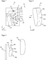
- FIG. 2 shows the optical element 24 in a three-dimensional view
- FIG. 3 illustrates an exemplary arrangement of the optical element 24 between receiving optics 22 and light receiver 26 illustrated, ie in the convergent beam path of the remitted light beam 20 after bundling by the receiving optical system 22.
- the optical element 24 is here a free-form lens, so based on refraction.
- a reflexive effect ie a mirror with a corresponding contour, or a diffractive optical element would also be possible.
- the optical element 24 has a front surface 34a and a rear surface 34b, both of which are formed as free-form surfaces. It would also be conceivable to form one of the surfaces 34a-b plan, whereby, however, the degrees of freedom of the optimization are reduced.
- the optical element 24 In the Y direction, in which the light emitter 12 and the light receiver 26 are spaced from each other and in which the receiving light spot travels in dependence on the object distance, the optical element 24 exhibits a wave-like contour. This results in a converging subregion 24a and, with a transition region 24b, a diverging subregion 24c. The wave-like contour is more pronounced on the front surface 34a than on the rear surface 34b. This leads to a bulbous overall shape.
- the subregions 24a-c merge without sharp demarcation.
- the optical element 24 is, to a first approximation, an extrusion body in which the wave-like contour is repeated in each cut.
- this is only the basic form, which is then further optimized with regard to the desired beam shaping effect to be explained.
- incident light bundles must be considered.
- the optical element 24 is trimmed at the sides. This creates a rectangular or trapezoidal frame or a total cuboid shape. This has little effect on the beam forming properties, but simplifies handling, placement and mounting.
- the illustrated shape of the optical element 24 is the result of an optimization whose goal is that in the Y direction as in the X direction focusing on the Auf Economicsquerrough and incidence of the remitted light beam 20 on the optical element 24, thus ultimately dependent on the object distance or to achieve defocusing with an effective concentration and / or mixture of partial pupil bundles.
- the effect in the Y and X directions will generally be different.
- a prismatic tilting of the midpoint beams in the direction of the surface normal of the light receiver 26 is likewise to be achieved as a function of the object distance.
- optical element 24 The same optimization goals may also lead to a different shape of the optical element 24.
- the converging section 24a and the divergent section 24c will be preserved in the optimization.
- the detailed shape is not limited to the illustrated optical element 24.
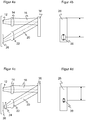
- FIGS. 4 to 6 illustrate the improved beam path on the optical element 24 at a near, middle and far range, so a probed object 36 at a corresponding distance. It is always first for reference as FIG. 4a . 5a or 6a the beam path in a conventional sensor without the optical element 24 and as Figure 4c . 5c or 6c the beam path in a sensor 10 according to the invention is shown. The others FIGS. 4b . 5b . 6b and 4d . 5d . 6d show the respective associated receiving light spot 38 on the light receiver 26.
- the receiving optics 22 in this example is a single converging receiver lens that is focused to sharply image the object 36 on the light receiver 26 in a medium range of range. For smaller and larger scanning distances, however, the image is blurred and thus the energy distribution of the receiving light spot 38 is less concentrated on the light receiver 26.
- the change in position of the receiving light spot 38 on the light receiver per scanning distance change is in the vicinity big and small in the distance.
- One possibility is to determine the position of the receiving light spot 38, the unweighted center of gravity or else the median of the energy distribution of the receiving light spot 38.
- the optical element 24 now effects an energy concentration at least in the near and far range as well as a deflection of the position of the median of the receiving light spot 38 from the respective center beam, specifically in the near range to the center beam and in the far range away from the center beam.
- the incident remitted light beam 20 is additionally focused by the convex lens surface of the converging portion 24 a, and thereby the energy is concentrated on the light receiver 26. Without the effect of the converging portion 24a, the image of the object 36 would be behind the light receiver 26 and, accordingly, the energy of the receiving light spot 38 on the light receiver 26 would be less concentrated. In addition, the received light spot 38 is tilted significantly prismatic upwards.
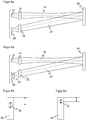
- the incident remitted light beam 20 is largely unaffected by the optical element 24 and thereby largely maintained by the receiving optics 22 already focused position and shape of the receiving light spot 28.
- Such a remitted light beam 20 mainly falls on the neutral transition region 24b of the optical element.
- the incident remitted light beam is defocused by the concave lens surface of the divergent portion 24c. This also leads to a concentration of the energy on the light receiver 26, because without the effect of the diverging portion 24c, the image of the object 36 would be in front of the light receiver 26, and accordingly the receiving light spot 38 would be less concentrated.
- the prismatic tilting of the receiving light spot 38 upward is significantly less pronounced in the far range than in the near range.
- optical element 24 contributes significantly to the fact that the scanning distance dependence of the light spot size and the nonlinearity of the offset of the receiving light spot 38 per scanning distance change is significantly reduced.
- Another problem of sensors according to the principle of triangulation are Sectionpupillenbeleuchtitch when capturing shiny objects 36. This will be explained first on the basis of FIG. 7 clarified.
- a background-blanking light scanner divides the surveillance area 18 into a foreground in which to switch when an object 36 is detected and a background to be hidden.
- the boundary 40 between foreground and background corresponds to the separating web 32.
- this limit 40 is evaluated with a switching hysteresis, as indicated by the hysteresis region 42. This prevents rapid toggling due to measurement variations in an object 36 near the boundary 40.
- a glossy object 36 can still lead to a miscalculation even outside hysteresis range 42 and tolerance interval 44, because under certain circumstances only part of the receiver pupil is illuminated and this leads to a considerable deviation of the range determination.
- a glossy object 36 does not reject light in all spatial directions corresponding to a Lambertian's characteristic, but in back reflection clearly prefers certain directions that depend on the orientation of the shiny or specular surface of the object 36.
- the receiver pupil is thereby only partially illuminated, such as in the upper, lower, right or left half of the lens or even smaller sections. If the object 36 is now not in the image width of the receiving optics 22, that is to say in the middle distance range, then without the optical element 24 the object 36 is displayed blurred. Depending on which part of the receiver pupil is illuminated, this results in a different median position on the light receiver 26 and thus an error in determining the scanning distance.
- Figure 7a shows a fault for a too far shiny object 36, which would actually have to be hidden.
- a sub-beam 20a of the remitted light beam 20 only illuminates a lower part of the receiving optical system 22. Accordingly, much energy falls on the short-range element 26a, and the sensor 10 turns on.
- the ideal center beam 46 on the other hand, would strike the far-range element 26b and blank out correctly.
- FIG. 7b shows a corresponding error case with a near shiny object 36, which is mistakenly overlooked.
- a sub-beam 20a of the remitted light beam 20 illuminates only the upper part of the receiving optics 22, and thereby much energy falls on the far-range element 26b, causing a false background suppression.
- the ideal center beam 46 would strike the proximity area element 26a and then turn on the sensor 10.
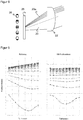
- FIG. 8 again shows the effects of sectionpupillenbeleuchtung without the optical element 24.
- the optical element 24 also minimizes these undesirable effects by partial pupil illumination without affecting the other sensor performance, because the received light spot 38 is much better focused in the near and far range. As a result, the median shift has a much lower impact on the measurement.
- FIG. 9 the optical element 24 in partial pupil illumination FIG. 9 illustrated.
- the receiving optics 22 is in a simulation only in one of ten superimposed strips similar to the representation in FIG. 8 illuminated. These stripes or subregions are plotted on the x-axis.
- the Y axis represents the respective median position, with one curve each for different detection ranges.
- the left graphic of the FIG. 9 is a reference without the optical element 24, the right graph shows the improvement by the invention.
- the switching behavior is significantly more robust against partial illuminations of the receiver pupil, as they occur primarily in the detection of shiny objects 36, or the measurement accuracy of the distance is much more accurate.
- the momentum-dependent beam shaping by the optical element 24 results in effective homogenization of the partial pupil sensitivity, improvements in the triangulating energy density and at least some compression and linearization of the triangulation curve, ie the position of the median of the receiving light spot 38 as a function of the scanning distance or the object distance. This results in a reduced range-dependence of the sensor 10 on remission characteristics of the objects and a simplification and improvement of the range adjustment useful to the user.
- the discrimination of the foreground against the background strongly depends on the triangulating energy density, which should therefore be as large as possible.
- the setting range is determined by the distance between the maximum and minimum position of the median, which should therefore be compressed as much as possible.
- the setting precision after all depends on the Linearity of triangulation dynamics. All three effects are additionally improved by the optical element 24 in a wide range.
- the optical element 24 can also be used as an optical filter. If the remitted light bundle 20 is attenuated in the near range, that is to say by the converging subregion 24a, by roughening, path mirroring, absorbing or the like, then the total energy in the near range can be reduced and thus the energetic distance characteristic can be adapted. As a result, the required dynamic range of the light receiver 26 subsequent evaluation circuits is reduced, with the advantages of lower costs, heat loss and noise.
- a free-form lens can in principle be made of plastic or glass and thereby combined with functional surface or volume properties of this material or additionally applied layers. Examples are spectral filtering, spatial filtering, whether homogeneous, inhomogeneous or structured, volume or surface scattering, fluorescence or luminescence, polarization filtering, for example by wire-grid polarizer layers and diffractive-optical properties.
Abstract
Es wird ein optoelektronischer Sensor (10) nach dem Prinzip der Triangulation zur Erfassung eines Objekts (36) in einem Überwachungsbereich (18) mit einem Lichtsender (12) zum Aussenden eines Lichtbündels (16) und einem um einen Basisabstand gegen den Lichtsender (12) versetzt angeordneten ortsauflösenden Lichtempfänger (26) zum Empfangen des von dem Objekt (36) remittierten Lichtbündels (20) angegeben, wobei dem Lichtempfänger (26) eine Empfangsoptik (22) sowie ein optisches Element (24) zwischen Lichtempfänger (12) und Empfangsoptik (22) vorgeordnet ist. Dabei weist das optisches Element (24) einen konvergierenden Teilbereich (24a) und einen divergierenden Teilbereich (24c) auf und ist so angeordnet, dass ein remittiertes Lichtbündel (20) von einem Objekt (36) in einem Nahbereich des Überwachungsbereichs (18) durch den konvergierenden Teilbereich (24a) und ein remittiertes Lichtbündel (20) aus einem Fernbereich des Überwachungsbereichs (18) durch den divergierenden Teilbereich (24c) fällt.The invention relates to an optoelectronic sensor (10) according to the principle of triangulation for detecting an object (36) in a monitoring area (18) with a light transmitter (12) for emitting a light beam (16) and at a base distance from the light transmitter (12). staggered arranged spatially resolving light receiver (26) for receiving the remitted from the object (36) light beam (20), wherein the light receiver (26) receiving optics (22) and an optical element (24) between light receiver (12) and receiving optics (22 ) is arranged upstream. In this case, the optical element (24) has a converging subregion (24a) and a diverging subregion (24c) and is arranged such that a remitted light bundle (20) from an object (36) in a vicinity of the surveillance region (18) through the converging portion (24a) and a remitted light beam (20) from a remote area of the monitoring area (18) by the diverging portion (24c) falls.
Description
Die Erfindung betrifft einen optoelektronischen Sensor und ein Verfahren zur Erfassung eines Objekts nach dem Prinzip der Triangulation gemäß dem Oberbegriff von Anspruch 1 beziehungsweise 14.The invention relates to an optoelectronic sensor and a method for detecting an object according to the principle of triangulation according to the preamble of
Das Prinzip der optischen Triangulation beruht darauf, einen Lichtsender und einen ortsauflösenden Lichtempfänger um einen bekannten Basisabstand gegeneinander versetzt anzuordnen. Sende- und Empfangslichtstrahl stehen dann in einem Winkel zueinander, was dazu führt, dass der Empfangslichtfleck auf dem Empfänger in Abhängigkeit von dem Abstand zu dem angetasteten Objekt wandert. Die Position des Empfangslichtflecks auf dem ortsauflösenden Lichtempfänger ist demnach ein Maß für den Objektabstand.The principle of optical triangulation is based on arranging a light transmitter and a spatially resolving light receiver offset from one another by a known base distance. The transmitted and received light beams are then at an angle to each other, resulting in that the receiving light spot on the receiver moves depending on the distance to the touched object. The position of the receiving light spot on the spatially resolving light receiver is therefore a measure of the object distance.
Es gibt nicht nur messende Triangulationstaster, die in der skizzierten Weise einen Abstand bestimmen und ausgeben, sondern auch schaltende Systeme nach dem Triangulationsprinzip, deren Schaltverhalten von dem Objektabstand abhängt. Zu diesen Sensoren gehören die hintergrundausblendenden Lichttaster. Sie sind schaltend, geben also lediglich ein binäres Objektfeststellungsignal aus. Zugleich wird aber der Aufbau eines Triangulationstasters ausgenutzt, um mit einem zumindest in einen Nah- und einen Fernbereich ortsauflösenden Lichtempfänger zwei Empfangssignale zu erzeugen. Deren Differenz wird mit einer Schaltschwelle bewertet, um so die Objekterfassung auf einen bestimmten Entfernungsbereich zu beschränken und Empfangssignale von Objekten außerhalb dieses Entfernungsbereichs als Hintergrundsignal auszublenden. Ein hintergrundausblendender Lichttaster ist beispielsweise in der
Die Beziehung zwischen Objektabstand und Verschiebung des Empfangslichtflecks auf dem Lichtempfänger ist nichtlinear. Abstandsänderungen im Nahbereich führen zu großen, im Fernbereich dagegen nur zu kleinen Verschiebungen des Empfangslichtflecks. Zugleich ist der Empfangslichtfleck kein idealer mathematischer Punkt und dessen Ausdehnung zudem erneut vom Objektabstand abhängig, da die Empfangsoptik nicht den gesamten Abstandsbereich scharf abbilden kann. Diese Effekte führen zu Messungenauigkeiten und im Falle von hintergrundausblendenden Lichttastern zu einer Schaltpunktabweichung und damit zumindest manchmal zum Fehlschalten.The relationship between object distance and displacement of the receiving light spot on the light receiver is non-linear. Distance changes in the near range lead to large, in the far range, however, only small shifts of the received light spot. At the same time, the received light spot is not an ideal mathematical point and its extension is again dependent on the object distance since the receiving optics can not sharply map the entire distance range. These effects lead to measurement inaccuracies and, in the case of background-blanking light sensors, to a switching point deviation and thus at least sometimes to a faulty switching.
Besonders schwerwiegend sind diese Probleme bei glänzenden Objekten, weil dann die Empfängerpupille möglicherweise nur teilweise ausgeleuchtet wird. Es gibt zwar Sensoren, die sich speziell mit Glanzerkennung befassen. Dabei geht es dann aber darum, das glänzende Objekt überhaupt zu erfassen oder dessen Glanzgrad zu bestimmen. Eine triangulierende Abstandsbestimmung oder Hintergrundunterdrückung ist nicht vorgesehen und würde durch die speziell für Glanzerkennung eingeführten Maßnahmen auch nicht gelöst.These problems are particularly serious for shiny objects, because then the receiver pupil may be only partially illuminated. There are sensors that deal specifically with gloss detection. But then it's about capturing the glossy object or determining its gloss level. A triangulating distance determination or background suppression is not provided and would not be solved by the measures specially introduced for gloss detection.
Es gibt im Stand der Technik Ansätze, die Empfangsoptik zu verbessern, um die Linearität zu verbessern oder den Messbereich für besonders nahe Objekte zu erweitern. Beispielsweise nutzt die
Die
Außer durch Triangulation ist optische Distanzmessung auch in koaxialen Systemen möglich, beispielsweise durch Lichtlaufzeitmessung. Damit dort die Empfangsoptik mit unterschiedlichen Entfernungen umgehen kann, werden sogenannte Mehrzonenlinsen eingesetzt, in denen konzentrische Ringe für bestimmte Abstandsbereiche zuständig sind, wie dies etwa in der
Zum Aspekt einer Teilausleuchtung bei glänzenden Objekten tragen die bekannten Lösungen gar nichts bei.The known solutions do not contribute anything to the aspect of partial illumination in the case of glossy objects.
Es ist daher Aufgabe der Erfindung, die Genauigkeit der optischen Triangulation zu verbessern.It is therefore an object of the invention to improve the accuracy of the optical triangulation.
Diese Aufgabe wird durch einen optoelektronischen Sensor und ein Verfahren zur Erfassung eines Objekts nach dem Prinzip der Triangulation gemäß Anspruch 1 beziehungsweise 14 gelöst. Dazu wird wie bei der optischen Triangulation üblich ein Lichtbündel in den Überwachungsbereich ausgesandt und das dort von einem Objekt remittierte Lichtbündel in einem Lichtempfänger registriert. Das remittierte Lichtbündel kann sowohl durch diffuse Remission als auch durch gerichtete Reflexion entstehen. Lichtsender und Lichtempfänger sind in einem Basisabstand zueinander versetzt angeordnet. Aufgrund dieser Triangulationsbasis ist die Position des Empfangslichtflecks, den das remittierte Lichtbündel auf dem Lichtempfänger erzeugt, von dem auch als Tastweite bezeichneten Abstand des Objekts abhängig, und deshalb kann der Objektabstand trianguliert werden.This object is achieved by an optoelectronic sensor and a method for detecting an object according to the principle of triangulation according to
Die Erfindung geht nun von dem Grundgedanken aus, ein in der konvergenten Strahlebene angeordnetes optisches Element, also dort, wo das remittierte Lichtbündel bereits durch die Wirkung der Empfangsoptik konvergent ist, für die Triangulation sowohl im Nah- als auch im Fernbereich zu optimieren. Dazu weist das optische Element einen konvergierenden Teilbereich und einen divergierenden Teilbereich auf und ist so angeordnet, dass ein remittiertes Lichtbündel aus dem Nahbereich durch den konvergierenden Teilbereich und ein remittiertes Lichtbündel aus dem Fernbereich durch den divergierenden Teilbereich fällt. Denn die Empfangsoptik selbst kann nur für einen bestimmten Tastweitenbereich scharf abbilden. Durch die unterschiedliche Wirkung des optischen Elements in Nahbereich und Fernbereich wird jeweils für eine Linearisierung und eine schärfere Abbildung des Empfangslichtflecks gesorgt. Außerdem bewirkt das optische Element eine effektive Konzentration beziehungsweise Mischung von Teilpupillenbündeln und somit eine homogenere Lichtverteilung im Empfangslichtfleck insbesondere bei glänzenden Objekten.The invention is based on the basic idea of optimizing an optical element arranged in the convergent beam plane, ie where the remitted light beam is already convergent by the effect of the receiving optics, for triangulation both in the near and far range. For this purpose, the optical element has a converging partial area and a diverging partial area and is arranged such that a remitted light beam from the near area passes through the converging partial area and a remitted light bundle from the far range through the diverging partial area. Because the receiving optics itself can only reflect sharply for a specific scanning range. Due to the different effect of the optical element in the near and far range, a linearization and a sharper image of the receiving light spot are provided in each case. In addition, this causes optical element an effective concentration or mixture of Teilpupillenbündeln and thus a more homogeneous light distribution in the receiving light spot, especially in shiny objects.
Die Erfindung hat also den Vorteil, dass durch die verbesserte Optik im Empfangspfad die Lichtfleckposition schärfer definiert ist und damit genauer bestimmt werden kann. Dies führt bei schaltenden Systemen, wie hintergrundausblendenden Lichttastern, zu einem präziser eingehaltenen Schaltpunkt und verhindert Fehlschalten. Außerdem werden auch glänzende Objekte zuverlässig erkannt, obwohl das von diesen Objekten reflektierte Lichtbündel möglicherweise nur eine Teilpupille der gesamten Empfängerpupille ausleuchtet.The invention thus has the advantage that the light spot position is defined sharper by the improved optics in the receiving path and thus can be determined more accurately. In switching systems, such as background-blanking light sensors, this leads to a more precisely maintained switching point and prevents faulty switching. In addition, glossy objects are reliably detected, although the light beam reflected from these objects may illuminate only a partial pupil of the entire receptor pupil.
Im Folgenden ist es manchmal einfacher, sich auf ein Koordinatensystem zu beziehen, in dem ohne jede Einschränkung der Allgemeinheit die Y-Achse Lichtsender und Lichtempfänger verbindet und somit die Richtung bezeichnet, in welcher der Empfangslichtfleck auf dem Lichtempfänger wandert, die Z-Achse die optische Achse des Lichtsenders ist und damit der Objektabstand längs der Z-Achse gemessen wird, und die X-Achse die verbleibende dritte Achse senkrecht zur Y-Achse und Z-Achse ist.In the following, it is sometimes easier to refer to a coordinate system in which, without any restriction of generality, the Y-axis connects the light emitter and the light receiver and thus indicates the direction in which the receiving light spot travels on the light receiver, the Z-axis the optical Is the axis of the light emitter and thus the object distance along the Z-axis is measured, and the X-axis is the remaining third axis perpendicular to the Y-axis and Z-axis.
Das optische Element weist bevorzugt einen neutralen Teilbereich zwischen dem konvergierenden Teilbereich und dem divergierenden Teilbereich auf. Die Empfangsoptik ist selbst für einen mittleren Objektabstand zwischen Nah- und Fernbereich auf den Lichtempfänger fokussiert. Dann ist keine zusätzliche Strahlformung erforderlich. Der neutrale Teilbereich schafft einen kontinuierlichen Übergang zwischen dem konvergierenden Teilbereich und dem divergierenden Teilbereich, der auch die Herstellung und Anordnung des optischen Elements vereinfachen kann.The optical element preferably has a neutral subregion between the converging subregion and the diverging subregion. The receiving optics is focused on the light receiver even for a medium object distance between the near and far range. Then no additional beam forming is required. The neutral portion provides a continuous transition between the converging portion and the diverging portion, which can also simplify the fabrication and arrangement of the optical element.
Das optische Element weist bevorzugt eine Freiformfläche mit dem konvergierenden Teilbereich und dem divergierenden Teilbereich auf. Das optische Element kann dabei auf Refraktion beruhen und wird dann vereinfachend als Linse bezeichnet, obwohl der Effekt anders ist als bei einer üblichen Sammel- oder Streulinse. Durch die Freiformfläche können die Strahlformwirkungen lokal angepasst werden, um insbesondere den unterschiedlichen Anforderungen in Nah- und Fernbereich gerecht zu werden. Bei einer Linse können Eintritts- und/oder Austrittsfläche Freiformflächen sein, oder eine der beiden Flächen bleibt plan oder zumindest in ihrer Geometrie deutlich weniger komplex oder ausgeprägt. Anstelle einer Linse kann auch ein reflexives Element, also ein Spiegel mit entsprechender Freiformfläche eingesetzt werden. Eine Alternative zu einer geometrischen Formung des optischen Elements ist ein diffraktives Element, das mit den gewünschten Beugungseffekten designt wird.The optical element preferably has a free-form surface with the converging partial region and the diverging partial region. The optical element may be based on refraction and is then referred to simply as a lens, although the effect is different than in a conventional collecting or scattering lens. Due to the free-form surface, the beam shaping effects can be locally adapted to meet in particular the different requirements in the near and far range. In the case of a lens, the entrance and / or exit surfaces can be free-form surfaces, or one of the two surfaces remains flat or at least significantly less complex or pronounced in its geometry. Instead of a lens can also be a reflective element, ie a mirror be used with appropriate free-form surface. An alternative to geometric shaping of the optical element is a diffractive element that is designed with the desired diffraction effects.
Die Freiformfläche weist bevorzugt lokale Krümmungen und/oder lokale Gradienten der Krümmung auf und fokussiert und/oder vermischt so Teilpupillenbündel des remittierten Lichtbündels. Die Freiform kann also durch lokale Krümmung für eine paraxiale Fokussierung und durch lokale Gradienten der Krümmung für eine Durchmischung der Teilbündel ausgelegt werden.The freeform surface preferably has local curvatures and / or local gradients of the curvature and thus focuses and / or mixes partial pupil bundles of the remitted light bundle. The free form can thus be designed by local curvature for a paraxial focusing and by local gradients of curvature for a thorough mixing of the sub-beams.
Ein Teilpupillenbündel ist ein Teilbündel, das nur einen Teil der Eintrittspupille beleuchtet. Zur Erläuterung sei hier ein paraxiales Teilbündel als ein minimales Teilbündel betrachtet, infinitesimal um die optische Achse des einfallenden Lichts herum. Dessen Fokussierung erfolgt durch die Kombination der lokalen Krümmungen auf beiden Seiten der Freiform. Man kann also die lokalen konvexen beziehungsweise konkaven lokalen Krümmungen der Freiform so wählen, dass sich eine Fokussierung auf eine gemeinsame Brennebene in der Ebene des Lichtempfängers einstellt. In diesem Zusammenhang ist Fokussierung allgemein im Sinne des Erreichens einer gemeinsamen Brennfläche zu verstehen, was möglicherweise auch eine Verlängerung der Brennweite bedeutet.A partial pupil bundle is a partial bundle that illuminates only part of the entrance pupil. For explanation, let us consider a paraxial sub-beam as a minimum sub-beam, infinitesimally around the optical axis of the incident light. Its focus is through the combination of local curvatures on both sides of the freeform. It is therefore possible to choose the local convex or concave local curvatures of the free-form in such a way that focus is set on a common focal plane in the plane of the light receiver. In this context, focussing is generally understood to mean reaching a common focal plane, which may also mean extending the focal length.
Die Durchmischung erfolgt dadurch, dass die Teilbündel aufgrund ihrer endlichen Ausdehnung gerade nicht ideal paraxial sind, sondern Bereiche der Freiform mit unterschiedlichen lokalen Krümmungen transmittieren, die aber nur für die Fokussierung eines paraxialen Teilbündels ausgelegt sind. Dadurch werden diese nicht-paraxialen realen Teilbündel beim Durchtritt durch die Freiform etwas weniger fokussiert und folglich aufgeweitet. Aufgrund der lokalen Krümmungsgradienten ergeben sich unterschiedliche Aufweitungsgrößen und Auftrefforte in Abhängigkeit von den unterschiedlichen Durchtrittsbereichen der Freiform. Deshalb durchmischen sich die Teilbündel. Der lokale Krümmungsgradient ist auf der Freiform erkennbar. Beispielsweise hat eine Welle aus einer konvexen und konkaven Form auf der Außenfläche einen lokalen Krümmungsgradienten, zwei aneinandergesetzte Zylinder haben dagegen eine konstante lokale Krümmung.The mixing takes place in that the partial bundles are not ideally paraxial due to their finite extent, but instead transmit areas of the freeform with different local curvatures, but which are designed only for the focusing of a paraxial sub-bundle. As a result, these non-paraxial real sub-bundles are slightly less focused and thus widened as they pass through the freeform. Due to the local curvature gradients, different expansion sizes and locations of impact arise as a function of the different passage areas of the free-form. Therefore, the sub-bundles mix. The local curvature gradient can be seen on the freeform. For example, a wave of a convex and concave shape on the outer surface has a local curvature gradient, but two juxtaposed cylinders have a constant local curvature.
Wie im modernen rechnergestützten Optikdesign üblich, lässt sich die durch Optimierungsverfahren entstehende Freiform nicht in einfachen Worten geometrisch beschreiben. Dazu sind die Formen zu komplex, und zudem können sich verschiedene zumindest nahezu gleichwirkende Optimierungen geometrisch stark unterscheiden. Die zu erzielende Strahlformungswirkung in Y-Richtung, also längs dem Basisabstand auf der Verbindungslinie von Lichtsender und Lichtempfänger, und der dazu senkrechten X-Richtung ist im Allgemeinen unterschiedlich und weitgehend unabhängig durch jeweilige Krümmungen oder Krümmungsgradienten in diesen beiden Richtungen quer zur Strahlrichtung einstellbar. Der Triangulationseffekt tritt in erster Betrachtung nur längs der Y-Richtung auf, was sich natürlich auf die zu optimierende Freiformfläche auswirkt.As usual in modern computer-aided optics design, the free form resulting from optimization processes can not be described geometrically in simple words. In addition, the shapes are too complex, and moreover, different optimizations, which have at least approximately the same effect, can differ greatly in terms of geometry. The beamforming effect to be achieved in the Y-direction, ie along the base distance on the line connecting the light transmitter and the light receiver, and the X direction perpendicular thereto is generally different and largely independently adjustable by respective curvatures or curvature gradients in these two directions transverse to the beam direction. The triangulation effect occurs in the first instance only along the Y-direction, which of course affects the freeform surface to be optimized.
Das optische Element weist bevorzugt in einem Schnitt längs des Basisabstands die Grundform einer einzelnen Welle auf. Die Welle verläuft längs des Basisabstands, also in Y-Richtung, und besteht aus einem konkaven und einem konvexen Bogen. Dadurch entstehen konvergierender und divergierender Teilbereich, wobei die Krümmung bei einem refraktiven optischen Element und einem reflexiven optischen Element natürlich komplementär ist. Grundform bedeutet hier und im Folgenden, dass Abweichungen für eine zusätzliche Optimierung denkbar sind, die aber den Ausgangspunkt, nämlich hier die Welle, weiterhin klar erkennen lassen.The optical element preferably has the basic shape of a single shaft in a section along the base distance. The shaft runs along the base distance, ie in the Y direction, and consists of a concave and a convex arc. This results in a converging and diverging partial region, the curvature being of course complementary in the case of a refractive optical element and a reflective optical element. The basic form here and in the following means that deviations are conceivable for additional optimization, but they still clearly reveal the starting point, namely the wave here.
Das optische Element weist bevorzugt die Grundform eines quer aus der Welle extrudierten Körpers auf. Die Form einer Welle entspringt zunächst einer zweidimensionalen Betrachtung. Durch Extrudieren in Querrichtung zu der Welle entsteht ein dreidimensionaler Körper der Linse oder des Spiegels, der in jedem Schnitt die Form der Welle aufweist.The optical element preferably has the basic shape of a body extruded transversely from the shaft. The shape of a wave initially arises from a two-dimensional view. By extruding in the transverse direction to the shaft, a three-dimensional body of the lens or the mirror is formed, which has the shape of the shaft in each section.
Das optische Element weist bevorzugt zusätzlich quer zu der Welle eine konvergierende Krümmung auf. Ein reiner Extrusionskörper wäre in X-Richtung plan. Natürlich kann aber auch hier die Formgebung der Freiformfläche zur weiteren Verbesserung beitragen. Eine konvergierende Wirkung macht den Empfangslichtfleck kleiner, sorgt somit für eine höhere Energiedichte. Diese Wirkung in X-Richtung gibt es im Gegensatz zu der Welle in Y-Richtung sowohl im Nah- wie im Fernbereich. Trotzdem kann vorzugsweise die Krümmung in Nah- und Fernbereich unterschiedlich stark ausgelegt sein, insbesondere im divergierenden Teilbereich beziehungsweise konkaven Fernbereich eine eher geringe und im konvergierenden Teilbereich beziehungsweise konvexen Nahbereich eine eher hohe Krümmung.The optical element preferably additionally has a converging curvature transverse to the shaft. A pure extrusion would be flat in the X direction. Of course, the shape of the free-form surface can contribute to further improvement. A converging effect makes the receiving light spot smaller, thus ensuring a higher energy density. This effect in the X direction, in contrast to the wave in the Y direction, exists both in the near and in the far range. Nevertheless, preferably the curvature in the near and far regions can be configured to be of varying intensity, in particular in the divergent subregion or concave far region a rather small curvature and, in the converging subregion or convex short region, a rather high curvature.
Die Freiformfläche ist bevorzugt aus der Grundform weiter optimiert, um schräg einfallende Lichtbündel zu berücksichtigen. Die bisherige Betrachtung war jeweils auf die X-Achse und die Y-Achse beschränkt. Das berücksichtigt die räumlichen Effekte noch nicht, denn es gibt natürlich auch schräg zu den Achsen einfallende Lichtanteile. Von der Grundform ausgehend können feinere Anpassungen der Freiformfläche dazu beitragen, dass solche schrägen Lichtbündel die gewünschten Strahlformungen nicht beeinträchtigen.The free-form surface is preferably further optimized from the basic shape in order to take into account obliquely incident light bundles. The previous consideration was limited to the X-axis and the Y-axis. This does not take into account the spatial effects, because of course there are also incident light portions to the axes. Starting from the basic form, finer adjustments of the free-form surface can contribute to such oblique light bundles not impairing the desired beam formations.
Das optische Element bewirkt bevorzugt zusätzlich eine prismatische Verkippung des remittierten Lichtbündels. Das kann durch Formgebung und/oder verkippte Anordnung des optischen Elements erreicht werden. Die prismatische Verkippung ist nochmals bevorzugt vom Auftreffpunkt des remittierten Lichtbündels abhängig, also je nach Objektabstand unterschiedlich stark ausgeprägt. Damit kann die prismatische Verkippung insbesondere zur Linearisierung der Triangulation beitragen.The optical element preferably additionally causes a prismatic tilting of the remitted light bundle. This can be achieved by shaping and / or tilted arrangement of the optical element. The prismatic tilting is again preferably dependent on the point of impact of the remitted light bundle, that is pronounced differently depending on the object distance. Thus, the prismatic tilting can contribute in particular to the linearization of the triangulation.
Das optische Element ist bevorzugt zu einem rechteckigen oder trapezförmigen Rahmen beschnitten. Das optische Element bildet also in einer Draufsicht ein Rechteck oder Trapez und ist damit insgesamt grob quaderförmig, abgesehen von der Freiformfläche auf Vorder- und/oder Rückseite, wo das remittierte Lichtbündel das optische Element durchdringt. Es entstehen also durch das Beschneiden optisch so gut wie keine Einbußen, während sich die Handhabung, Unterbringung und Halterung deutlich erleichtert.The optical element is preferably trimmed to a rectangular or trapezoidal frame. Thus, the optical element forms a rectangle or trapezium in a plan view and is therefore roughly cuboid overall, apart from the freeform surface on the front and / or back, where the remitted light beam penetrates the optical element. Thus, there are virtually no losses as a result of pruning, while the handling, accommodation and mounting are much easier.
Der divergierende Teilbereich weist bevorzugt Dämpfungseigenschaften für das remittierte Lichtbündel auf. Das lässt sich beispielsweise durch Aufrauen, Beschichten, Wegspiegeln oder Absorbieren an der Oberfläche oder im Material des optischen Elements erreichen. Im Nahbereich wird typischerweise zu viel Energie empfangen. Durch eine Dämpfung in dem optischen Element kann somit die Empfangsdynamik verringert werden, ohne dadurch die Detektionseigenschaften im Nahbereich zu beeinträchtigen.The diverging subregion preferably has attenuation properties for the remitted light bundle. This can be achieved, for example, by roughening, coating, mirroring or absorbing on the surface or in the material of the optical element. At close range, typically too much energy is received. By damping in the optical element, the reception dynamics can thus be reduced without thereby impairing the detection properties in the near range.
Das optische Element ist bevorzugt zugleich als optisches Filter ausgebildet. Erneut lässt sich das insbesondere durch Beschichtung oder Material erreichen, wobei hier aber nicht lediglich eine Dämpfung gemeint ist und der Effekt sich vorzugsweise auf das gesamte Empfangslicht und nicht nur den Nahbereich bezieht. Beispiele sind eine optische Bandpasswirkung, die auf die Wellenlänge des Lichtsenders abgestimmt ist, ein Polarisationsfilter oder allgemein diffraktiv-optische Eigenschaften.The optical element is preferably formed at the same time as an optical filter. Again, this can be achieved, in particular, by coating or material, but here not only attenuation is meant and the effect preferably relates to the entire received light and not only the near field. Examples are an optical bandpass effect tuned to the wavelength of the light emitter, a polarizing filter or generally diffractive-optical properties.
Der Sensor ist bevorzugt als hintergrundausblendender Lichttaster ausgebildet, bei dem der Lichtempfänger einen Nahbereich und einen Fernbereich mit einem Trennsteg dazwischen aufweist und der einen Schaltausgang aufweist, dessen Schaltzustand davon abhängt, ob ein Objekt im Nahbereich erfasst ist.The sensor is preferably designed as a background-blanking light sensor, in which the light receiver has a near zone and a far zone with a divider between them and which has a switching output whose switching state depends on whether an object is detected in the near zone.
Das Funktionsprinzip eines hintergrundausblendenden Lichttasters wurde einleitend kurz erläutert. Von der Lage des Trennstegs hängt ab, welche Signale als Hintergrund ausgeblendet werden. Deshalb sollte für eine präzise Detektion mit einer Entfernungsänderung des Objekts ein möglichst großer Lichtmengenanteil über den Trennsteg verschoben werden. Das wird durch das erfindungsgemäße optische Element erreicht. Der Trennsteg kann die physische Trennlinie zwischen einem Nah- und einem Fernempfangselement sein. Häufig ist ein virtueller Trennsteg gemeint, der elektronisch verstellbar ist, indem Einzellichtempfänger durch einfaches oder gewichtetes Zusammenschalten zu dem Nah- und Fernelement verbunden werden. Durch solche Gewichtungen ist sogar eine Verschiebung des Trennstegs mit Subpixelauflösung möglich.The functional principle of a background-blanking light sensor was briefly explained in the introduction. The position of the divider depends on which signals are hidden as background. Therefore, for a precise detection with a change in the distance of the object as large a proportion of light should be moved over the divider. This is achieved by the optical element according to the invention. The divider can be the physical divider between a near and a remote receiving element. It is often meant a virtual divider that is electronically adjustable by connecting individual light receivers to the near and far elements by simple or weighted interconnection. By such weights even a shift of the divider with subpixel resolution is possible.
Das erfindungsgemäße Verfahren kann auf ähnliche Weise weitergebildet werden und zeigt dabei ähnliche Vorteile. Derartige vorteilhafte Merkmale sind beispielhaft, aber nicht abschließend in den sich an die unabhängigen Ansprüche anschließenden Unteransprüchen beschrieben.The method according to the invention can be developed in a similar manner and shows similar advantages. Such advantageous features are described by way of example but not exhaustively in the subclaims following the independent claims.
Die Erfindung wird nachstehend auch hinsichtlich weiterer Merkmale und Vorteile beispielhaft anhand von Ausführungsformen und unter Bezug auf die beigefügte Zeichnung näher erläutert. Die Abbildungen der Zeichnung zeigen in:
- Fig. 1
- ein Blockschaltbild eines optoelektronischen Sensors nach dem Triangulationsprinzip;
- Fig. 2
- eine dreidimensionale Ansicht eines optischen Elements zur Anordnung zwischen Sendeoptik und Lichtempfänger;
- Fig. 3
- eine vergrößerte Detailansicht der Anordnung des optischen Elements zwischen Sendeoptik und Lichtempfänger;
- Fig. 4a
- ein beispielhafter Strahlverlauf in einem herkömmlichen Triangulationstaster mit einem Objekt im Nahbereich;
- Fig. 4b
- eine schematische Darstellung des Empfangslichtflecks auf dem Lichtempfänger in der Situation gemäß
Figur 4a ; - Fig. 4c
- ein beispielhafter Strahlverlauf ähnlich
Figur 4a jedoch in einem erfindungsgemäßen Sensor mit optischem Element zwischen Sendeoptik und Lichtempfänger; - Fig. 4d
- eine schematische Darstellung des Empfangslichtflecks auf dem Lichtempfänger in der Situation gemäß
Figur 4c ; - Fig. 5a-d
- Darstellungen analog den
Figuren 4a-d jedoch mit einem Objekt in einem mittleren Entfernungsbereich; - Fig. 6a-d
- Darstellungen analog den
Figuren 4a-d jedoch mit einem Objekt im Fernbereich; - Fig. 7a
- eine schematische Darstellung des Strahlverlaufs bei Erfassung eines glänzenden Objekts mit Teilpupillenbeleuchtung, die zu einem Fehlschalten führt;
- Fig. 7b
- eine Darstellung ähnlich
Figur 7a jedoch mit näherem glänzenden Objekt, das nun fehlerhaft übersehen wird; - Fig. 8
- eine Darstellung von Teilstrahlenbündeln des remittierten Lichtbündels und der dadurch bewirkten Teilpupillenbeleuchtung; und
- Fig. 9
- ein Vergleich der Lichtfleckposition bei verschiedenen Teilpupillenbeleuchtungen in einem Referenzfall ohne das optische Element und gemäß Erfindung mit dem optischen Element.
- Fig. 1
- a block diagram of an optoelectronic sensor according to the triangulation principle;
- Fig. 2
- a three-dimensional view of an optical element for arrangement between the transmitting optical system and the light receiver;
- Fig. 3
- an enlarged detail view of the arrangement of the optical element between the transmitting optical system and the light receiver;
- Fig. 4a
- an exemplary beam path in a conventional triangulation with an object in the vicinity of;
- Fig. 4b
- a schematic representation of the received light spot on the light receiver in the situation according to
FIG. 4a ; - Fig. 4c
- an exemplary beam path similar
FIG. 4a however, in a sensor according to the invention with an optical element between the transmission optics and the light receiver; - Fig. 4d
- a schematic representation of the received light spot on the light receiver in the situation according to
Figure 4c ; - Fig. 5a-d
- Representations analogous to
FIGS. 4a-d but with an object in a medium distance range; - Fig. 6a-d
- Representations analogous to
FIGS. 4a-d however, with an object in the far field; - Fig. 7a
- a schematic representation of the beam path upon detection of a shiny object with Teilpupillenbeleuchtung, resulting in a mishandling;
- Fig. 7b
- a representation similar
Figure 7a but with a closer shiny object that is now overlooked erroneously; - Fig. 8
- a representation of partial beams of the remitted light beam and thereby caused Teilpupillenbeleuchtung; and
- Fig. 9
- a comparison of the light spot position at different Teilpupillenbeleuchtungen in a reference case without the optical element and according to the invention with the optical element.
Eine Empfangsoptik 22 bündelt das remittierte Lichtbündel 20. Anschließend wird das remittierte Lichtbündel 20 in einem optischen Element 24 weiter strahlgeformt und fällt dann auf einen Lichtempfänger 26, der daraus ein elektrisches Empfangssignal erzeugt. In der dargestellten Ausführungsform des Sensors 10 ist eine Hintergrundausblendung vorgesehen. Deshalb ist der Lichtempfänger 26 in ein Nahbereichselement 26a und ein Fernbereichselement 26b unterteilt. Der Auftreffort des remittierten Lichtbündels 20 beziehungsweise des davon erzeugten Empfangslichtflecks auf dem Lichtempfänger 26 hängt wegen der Triangulationsanordnung in dem Sensor 10 von der Entfernung des angetasteten Objekts ab, an dem das remittierte Lichtbündel 20 zurückgeworfen wird. Der Versatz zwischen Lichtsender 12 und Lichtempfänger 26 längs einer hier als Y-Achse bezeichneten Richtung bildet eine Triangulationsbasis. Das führt insbesondere dazu, dass der Empfangslichtfleck von einem fernen Objekt, also mit großem Abstand längs einer hier als Z-Achse bezeichneten Richtung, auf dem Fernbereichselement 26b und von einem nahen Objekt auf dem Nahbereichselement 26a registriert wird.A receiving
Eine Auswertungseinheit 28 ist mit dem Lichtempfänger 26 verbunden, um aus den elektrischen Empfangssignalen je nach Anwesenheit eines Objekts im Nahbereich ein Objektfeststellungssignal zu bestimmen, das an einem Schaltausgang 30 ausgegeben wird. Die Auswertungseinheit 28 bildet zur Hintergrundausblendung die Differenz zwischen dem Signal des Nahbereichselements 26a und des Fernbereichselements 26b und bewertet diese Differenz mit einer Schwelle. Dementsprechend wird an einem Schaltausgang 30 ein Schaltsignal erzeugt, dass eine Objektfeststellung anzeigt, wenn ein Objekt im Nahbereich detektiert wird, und keine Objektfeststellung, wenn kein Objekt oder nur ein Objekt im auszublendenden Fernbereich detektiert wird. Die Auswertungseinheit 28 steuert außerdem den Lichtsender 12.An
Anstelle eines zweielementigen Lichtempfängers 26 kann eine PSD (Position Sensitive Device) oder eine Empfängerzeile eingesetzt werden. Die Pixel der Empfängerzeile können eine unterschiedliche Breite aufweisen, um die nichtlineare Abhängigkeit der Verschiebung des Lichtflecks auf dem Lichtempfänger 26 von dem Abstand des Objekts zumindest teilweise auszugleichen. Für die Hintergrundausblendung wird per Werkseinstellung, Parametrierung oder Einlernen ein Trennsteg 32 definiert, der die Pixel in zwei Gruppen und damit den Lichtempfänger 26 in das Nah- und das Fernbereichselement 26a-b unterteilt. Die Lage des Trennstegs 32 kann elektronisch veränderbar sein.Instead of a two-
Die Ortsauflösung des Lichtempfängers 26 muss nicht notwendig nur für eine Unterteilung in Nah- und Fernbereich genutzt werden. Zum einen sind zusätzliche Trennstege und Entfernungsbereiche denkbar. Außerdem kann die Triangulation zu einer Entfernungsmessung statt zu einer Hintergrundausblendung verwendet werden, der Sensor 10 ist dann ein entfernungsmessender Triangulationstaster.The spatial resolution of the
Dies sind nur einige Aspekte, in denen der Aufbau des Sensors 10 gemäß
Das optische Element 24 weist eine Vorderfläche 34a und eine Rückfläche 34b auf, die beide als Freiformflächen ausgebildet sind. Es wäre auch denkbar, eine der Flächen 34a-b plan auszubilden, wodurch aber die Freiheitsgrade der Optimierung reduziert werden. In der Y-Richtung, in welcher Lichtsender 12 und Lichtempfänger 26 voneinander beabstandet sind und in welcher der Empfangslichtfleck in Abhängigkeit von dem Objektabstand wandert, zeigt das optische Element 24 eine wellenartige Kontur. Dadurch entstehen ein konvergierender Teilbereich 24a und, mit einem Übergangsbereich 24b, ein divergierender Teilbereich 24c. Die wellenartige Kontur ist auf der Vorderfläche 34a ausgeprägter als auf der Rückfläche 34b. Das führt zu einer bauchigen Gesamtform. Die Teilbereiche 24a-c gehen ohne scharfe Abgrenzung ineinander über. Außerdem ist auch vorstellbar, das optische Element 24 auf zwei Elemente für den Nahbereich und den Fernbereich aufzuteilen. Dann könnte sogar auf eines der beiden Elemente verzichtet werden, mit der absehbaren Folge, dass im entsprechenden Entfernungsbereich keine zusätzliche vorteilhafte Strahlformung stattfindet.The
In Quer- oder X-Richtung ist das optische Element 24 in erster Näherung ein Extrusionskörper, bei dem sich die wellenartige Kontur in jedem Schnitt wiederholt. Das ist allerdings nur die Grundform, die dann weiter im Hinblick auf die noch zu erläuternde angestrebte Strahlformungswirkung optimiert wird. Beispielsweise müssen im dreidimensionalen Raum schräg zu den Achsen einfallende Lichtbündel berücksichtigt werden. Außerdem kann es vorteilhaft sein, in X-Richtung insgesamt eine konvergierende Kontur vorzusehen, um das remittierte Lichtbündel 20 in dieser Achse zu konzentrieren.In the transverse or X direction, the
Das optische Element 24 ist an den Seiten beschnitten. Dadurch entsteht ein rechteckiger oder trapezförmiger Rahmen beziehungsweise eine insgesamt quaderähnliche Gestalt. Das hat kaum Auswirkungen auf die Strahlformungseigenschaften, vereinfacht aber die Handhabung, Unterbringung und Halterung.The
Die dargestellte Form des optischen Elements 24 ist das Ergebnis einer Optimierung, deren Ziel es ist, dass in Y-Richtung wie in X-Richtung eine vom Auftreffquerschnitt und Auftreffort des remittierten Lichtbündels 20 auf dem optischen Element 24, somit letztlich von dem Objektabstand abhängige Fokussierung beziehungsweise Defokussierung mit einer effektiven Konzentration und/oder Mischung von Teilpupillenbündeln zu erreichen. Dabei wird die Wirkung in Y- und X-Richtung im Allgemeinen unterschiedlich sein. Weiterhin soll ebenfalls in Abhängigkeit von dem Objektabstand eine prismatische Verkippung der Mittelpunktstrahlen in Richtung der Flächennormalen des Lichtempfängers 26 erzielt werden. Diese Effekte und deren Vorteile werden sogleich unter Bezugnahme auf die weiteren
Dieselben Optimierungsziele können auch zu einer abweichenden Form des optischen Elements 24 führen. Der konvergierende Teilbereich 24a und der divergierende Teilbereich 24c wird bei der Optimierung erhalten bleiben. Die detaillierte Formgebung ist aber auf das dargestellte optische Element 24 nicht beschränkt.The same optimization goals may also lead to a different shape of the
Die
Die Empfangsoptik 22 ist in diesem Beispiel eine einzelne konvergierende Empfängerlinse, die so fokussiert ist, dass sie das Objekt 36 in einem mittleren Tastweitenbereich scharf auf den Lichtempfänger 26 abbildet. Für kleinere und größere Tastweiten wird die Abbildung dagegen unscharf und damit die Energieverteilung des Empfangslichtflecks 38 auf dem Lichtempfänger 26 weniger konzentriert. Die Positionsänderung des Empfangslichtflecks 38 auf dem Lichtempfänger pro Tastweitenänderung ist im Nahbereich groß und im Fernbereich klein. Dabei ist eine Möglichkeit, die Position des Empfangslichtflecks 38 zu bestimmen, der ungewichtete Schwerpunkt oder auch Median der Energieverteilung des Empfangslichtflecks 38.The receiving
Das optische Element 24 bewirkt nun eine Energiekonzentration zumindest im Nahund Fernbereich sowie eine Ablenkung der Lage des Medians des Empfangslichtflecks 38 vom jeweiligen Mittelpunktstrahl, und zwar im Nahbereich hin zum Mittelpunktstrahl und im Fernbereich weg vom Mittelpunktstrahl.The
Im Nahbereich, der in
In einem mittleren Bereich, der in
Im Fernbereich, der in
Damit sind zwei Effekte des optischen Elements 24 veranschaulicht: Es trägt erheblich dazu bei, dass die Tastweitenabhängigkeit der Lichtfleckgröße sowie die Nichtlinearität des Versatzes des Empfangslichtflecks 38 je Tastweitenänderung deutlich reduziert ist. Ein weiteres Problem von Sensoren nach dem Prinzip der Triangulation sind Teilpupillenbeleuchtungen bei der Erfassung glänzender Objekte 36. Dies wird zunächst anhand der
Ein hintergrundausblendender Lichttaster unterteilt den Überwachungsbereich 18 in einen Vordergrund, in dem bei der Erfassung eines Objekts 36 geschaltet werden soll, und einen auszublendenden Hintergrund. Dabei entspricht die Grenze 40 zwischen Vorder- und Hintergrund dem Trennsteg 32. Allerdings wird in der Praxis diese Grenze 40 mit einer Schalthysterese ausgewertet, wie durch den Hysteresebereich 42 eingezeichnet. Das verhindert ein rasches Hin- und Herschalten aufgrund von Messschwankungen bei einem Objekt 36 nahe der Grenze 40.A background-blanking light scanner divides the
Bei derartigen Lichttastern tritt außerdem eine sogenannte Schwarz-Weiß-Verschiebung auf. Darunter versteht man eine scheinbare Entfernungsänderung aufgrund der Remissionseigenschaften von Objekten 36. Ein schwach remittierendes Objekt 36 erzeugt in einer anderen Entfernung ein über- beziehungsweise unterschwelliges Empfangssignal als ein stark remittierendes oder gar spiegelndes beziehungsweise glänzendes Objekt 36. Solange man die Remissionseigenschaften der zu detektierenden Objekte 36 nicht vorab kennt, führt dies also zu einer Messungenauigkeit. Dies wird durch ein weiteres Toleranzintervall 44 berücksichtigt.In such light sensors also occurs a so-called black and white shift. This is an apparent change in distance due to the remission properties of
Ein glänzendes Objekt 36 kann aber selbst außerhalb von Hysteresebereich 42 und Toleranzintervall 44 noch zu einem Fehlschalten führen, weil unter Umständen nur ein Teil der Empfängerpupille beleuchtet ist und dies eine erhebliche Abweichung der Tastweitenbestimmung nach sich zieht. Ein glänzendes Objekt 36 wirft Licht nicht entsprechend einer Lambert-Charakteristik in alle Raumrichtungen zurück, sondern bevorzugt in der Rückreflexion deutlich bestimmte Richtungen, die von der Orientierung der glänzenden oder spiegelnden Fläche des Objekts 36 abhängen. Die Empfängerpupille wird dadurch nur teilweise beleuchtet, etwa in der oberen, unteren, rechten oder linken Linsenhälfte oder noch kleineren Abschnitten. Befindet sich das Objekt 36 nun nicht in der Bildweite der Empfangsoptik 22, also im mittleren Entfernungsbereich, so wird ohne das optische Element 24 das Objekt 36 unscharf abgebildet. Je nachdem, welcher Teil der Empfängerpupille beleuchtet wird, ergibt sich also eine unterschiedliche Medianposition auf dem Lichtempfänger 26 und damit ein Fehler bei der Tastweitenbestimmung.However, a
Das optische Element 24 minimiert auch diese unerwünschten Effekte durch Teilpupillenbeleuchtung, ohne die sonstige Sensorperformance zu beeinträchtigen, denn der Empfangslichtfleck 38 ist auch im Nah- und Fernbereich wesentlich besser fokussiert. Dadurch wirkt sich die Medianverschiebung ungleich schwächer auf die Messung aus.The
Systematisch wird diese Verbesserung durch das optische Element 24 bei Teilpupillenbeleuchtung in
Die ideale Situation wäre, wenn sämtliche Kurven parallel zur X-Achse verliefen. Das würde nämlich heißen, dass die Medianposition gänzlich unabhängig davon ist, welcher Teil der Empfängerpupille beleuchtet wird. Die Lage der jeweiligen Kurve auf der Y-Achse würde allein von der Tastweite bestimmt. In der Referenz auf der linken Seite ist dies bei Weitem nicht der Fall, was nur eine summarische Darstellung der schon anhand von
Erfindungsgemäß verlaufen die Kurven, wie rechts in
Zusammenfassend ergeben sich wegen der tastweitenabhängigen Strahlformung durch das optische Element 24 eine effektive Homogenisierung der Teilpupillenempfindlichkeit, Verbesserungen der triangulierenden Energiedichte und zumindest eine gewisse Kompression und Linearisierung der Triangulationskurve, also der Position des Medians des Empfangslichtflecks 38 in Abhängigkeit von der Tastweite beziehungsweise dem Objektabstand. Daraus ergibt sich eine verringerte Tastweitenabhängigkeit des Sensors 10 von Remissionseigenschaften der Objekte und eine Vereinfachung und Verbesserung der für den Anwender nützlichen Tastweiteneinstellung.In summary, the momentum-dependent beam shaping by the
In Vergleichen mit Referenzen ähnlich der
Bei einem Sensor 10 nach dem Prinzip der Triangulation hängt die Diskriminierung des Vordergrundes gegenüber dem Hintergrund stark von der triangulierenden Energiedichte ab, die also möglichst groß sein soll. Der Einstellbereich wird durch den Abstand zwischen maximaler und minimaler Lage des Medians bestimmt, der also möglichst komprimiert werden sollte. Die Einstellungspräzision schließlich ist abhängig von der Linearität der Triangulationsdynamik. Sämtliche drei Effekte werden durch das optische Element 24 in einem weiten Bereich zusätzlich verbessert.In a
Über die beschriebenen Strahlformungseigenschaften hinaus kann das optische Element 24 auch als optisches Filter eingesetzt werden. Wird das remittierte Lichtbündel 20 im Nahbereich, also durch den konvergierenden Teilbereich 24a, durch Aufrauen, Wegspiegeln, Absorbieren oder dergleichen bedämpft, so kann die Gesamtenergie im Nahbereich reduziert und so die energetische Abstandscharakteristik angepasst werden. Hierdurch wird der benötigte Dynamikumfang der dem Lichtempfänger 26 nachfolgenden Auswerteschaltungen reduziert, mit den Vorteilen geringerer Kosten, Verlustwärme und Rauschens.In addition to the described beam shaping properties, the
Auch ansonsten lassen sich zusätzliche Funktionen in das optische Element 24 integrieren. Als transparentes Funktionsteil lässt sich eine Freiformlinse prinzipiell aus Kunststoff oder Glas herstellen und dadurch mit funktionalen Oberflächen- oder Volumeneigenschaften dieses Materials oder zusätzlich aufgebrachten Schichten kombinieren. Beispiele sind spektrale Befilterung, räumliche Befilterung, sei sie homogen, inhomogen oder strukturiert, Volumen- oder Oberflächenstreuung, Fluoreszenz oder Lumineszenz, Polarisationsfilterung beispielsweise durch Wire-Grid Polarisatorschichten und diffraktiv-optischen Eigenschaften.Otherwise, additional functions can be integrated into the
Claims (14)
dadurch gekennzeichnet,
dass das optisches Element (24) einen konvergierenden Teilbereich (24a) und einen divergierenden Teilbereich (24c) aufweist und so angeordnet ist, dass ein remittiertes Lichtbündel (20) von einem Objekt (36) in einem Nahbereich des Überwachungsbereichs (18) durch den konvergierenden Teilbereich (24a) und ein remittiertes Lichtbündel (20) aus einem Fernbereich des Überwachungsbereichs (18) durch den divergierenden Teilbereich (24c) fällt.Optoelectronic sensor (10) according to the principle of triangulation for detecting an object (36) in a surveillance area (18) with a light emitter (12) for emitting a light beam (16) and a spatially resolving offset by a base distance from the light emitter (12) A light receiver (26) for receiving the light beam (20) remitted by the object (36), wherein a receiving optics (22) and an optical element (24) are arranged upstream of the light receiver (26) between the light receiver (12) and the receiving optics (22),
characterized,
in that the optical element (24) has a converging subregion (24a) and a diverging subregion (24c) and is arranged such that a remitted light bundle (20) from an object (36) in a near region of the surveillance region (18) passes through the converging Part area (24a) and a remitted light beam (20) from a remote area of the monitoring area (18) by the divergent portion (24c) falls.
wobei das optische Element (24) einen neutralen Teilbereich (24b) zwischen dem konvergierenden Teilbereich (24a) und dem divergierenden Teilbereich (24c) aufweist.Sensor (10) according to claim 1,
wherein the optical element (24) has a neutral portion (24b) between the converging portion (24a) and the divergent portion (24c).
wobei das optische Element (24) eine Freiformfläche (34a-b) mit dem konvergierenden Teilbereich (24a) und dem divergierenden Teilbereich (24c) aufweist.Sensor (10) according to claim 1 or 2,
wherein the optical element (24) has a free-form surface (34a-b) with the converging partial region (24a) and the diverging partial region (24c).
wobei die Freiformfläche (34a-b) lokale Krümmungen und/oder lokale Gradienten der Krümmung aufweist und so Teilpupillenbündel (20a) des remittierten Lichtbündels (20) konzentriert und/oder vermischt.Sensor (10) according to claim 3,
wherein the free-form surface (34a-b) has local curvatures and / or local gradients of the curvature and thus concentrates and / or mixes partial pupil bundles (20a) of the remitted light bundle (20).
wobei das optische Element (24) in einem Schnitt längs des Basisabstands die Grundform einer einzelnen Welle aufweist.Sensor (10) according to claim 3 or 4,
wherein the optical element (24) in a section along the base distance has the basic shape of a single shaft.
wobei das optische Element (24) die Grundform eines quer aus der Welle extrudierten Körpers aufweist.Sensor (10) according to claim 5,
wherein the optical element (24) has the basic shape of a body extruded transversely from the shaft.
wobei das optische Element (24) zusätzlich quer zu der Welle eine konvergierende Krümmung aufweist.Sensor (10) according to claim 5 or 6,
wherein the optical element (24) additionally has a converging curvature transverse to the shaft.
wobei die Freiformfläche (34a-b) aus der Grundform weiter optimiert ist, um schräg einfallende Lichtbündel zu berücksichtigen.Sensor (10) according to one of claims 5 to 7,
wherein the freeform surface (34a-b) is further optimized from the basic shape to account for obliquely incident light bundles.
wobei das optische Element (24) zusätzlich eine prismatische Verkippung des remittierten Lichtbündels (20) bewirkt.Sensor (10) according to one of the preceding claims,
wherein the optical element (24) additionally causes a prismatic tilting of the remitted light beam (20).
wobei das optische Element (24) zu einem rechteckigen oder trapezförmigen Rahmen beschnitten ist.Sensor (10) according to one of the preceding claims,
wherein the optical element (24) is trimmed to a rectangular or trapezoidal frame.
wobei der divergierende Teilbereich (24c) Dämpfungseigenschaften für das remittierte Lichtbündel (20) aufweist.Sensor (10) according to one of the preceding claims,
wherein the divergent portion (24c) has attenuation characteristics for the remitted light bundle (20).
wobei das optische Element (24) zugleich als optisches Filter ausgebildet ist.Sensor (10) according to one of the preceding claims,
wherein the optical element (24) is at the same time designed as an optical filter.
der als hintergrundausblendender Lichttaster ausgebildet ist, bei dem der Lichtempfänger (26) einen Nahbereich (26a) und einen Fernbereich (26b) mit einem Trennsteg (32) dazwischen aufweist und der einen Schaltausgang (30) aufweist, dessen Schaltzustand davon abhängt, ob ein Objekt (36) im Nahbereich erfasst ist.Sensor (10) according to one of the preceding claims,
is formed as a background-blanking light sensor, in which the light receiver (26) has a short range (26a) and a long range (26b) with a divider (32) in between and which has a switching output (30) whose switching state depends on whether an object (36) is recorded at close range.
dadurch gekennzeichnet,
dass ein von einem Objekt (36) in einem Nahbereich des Überwachungsbereichs (18) remittiertes Lichtbündel (20) in einem konvergierenden Teilbereich (24a) des optischen Elements (24) und ein von einem Objekt (36) in einem Fernbereich des Überwachungsbereichs (18) remittiertes Lichtbündel (20) in einem divergierenden Teilbereich (24c) des optischen Elements (24) strahlgeformt wird.Method for detecting an object (36) in a monitoring area (18) according to the principle of triangulation, in which a light beam (16) is emitted and a receiving position of the light bundle (20) remitted on the object (36) is determined, wherein the remitted light bundle (20) is first bundled in a receiving optical system (22) and then additionally beam-formed in an optical element (24),
characterized,
in that a light bundle (20) remitted by an object (36) in a near area of the surveillance area (18) is located in a converging subarea (24a) of the optical element (24) and an object (36) in a remote area of the surveillance area (18) remitted light beam (20) in a diverging portion (24c) of the optical element (24) is beam-shaped.
Applications Claiming Priority (1)
| Application Number | Priority Date | Filing Date | Title |
|---|---|---|---|
| DE102015119668.9A DE102015119668B3 (en) | 2015-11-13 | 2015-11-13 | Optoelectronic sensor and method for detecting an object |
Publications (2)
| Publication Number | Publication Date |
|---|---|
| EP3168642A1 true EP3168642A1 (en) | 2017-05-17 |
| EP3168642B1 EP3168642B1 (en) | 2018-01-24 |
Family
ID=57113156
Family Applications (1)
| Application Number | Title | Priority Date | Filing Date |
|---|---|---|---|
| EP16192730.6A Active EP3168642B1 (en) | 2015-11-13 | 2016-10-07 | Optoelectronic sensor and method for detecting an object |
Country Status (4)
| Country | Link |
|---|---|
| US (1) | US10761193B2 (en) |
| EP (1) | EP3168642B1 (en) |
| JP (1) | JP6416171B2 (en) |
| DE (1) | DE102015119668B3 (en) |
Families Citing this family (6)
| Publication number | Priority date | Publication date | Assignee | Title |
|---|---|---|---|---|
| KR20200114860A (en) * | 2019-03-29 | 2020-10-07 | 삼성전자주식회사 | Wide-angle high resolution distance measuring device |
| JP7354716B2 (en) * | 2019-09-20 | 2023-10-03 | 株式会社デンソーウェーブ | Laser radar equipment and lenses for laser radar equipment |
| CN113030910A (en) * | 2019-12-09 | 2021-06-25 | 觉芯电子(无锡)有限公司 | Laser radar system |
| DE102020112091A1 (en) * | 2020-05-05 | 2021-11-11 | Sick Ag | Photoelectric sensor |
| DE102021119423A1 (en) | 2021-07-27 | 2023-02-02 | Sick Ag | Photoelectric sensor and method for detecting an object using the triangulation principle |
| EP4310443A1 (en) * | 2022-07-21 | 2024-01-24 | Leuze electronic GmbH + Co. KG | Optical triangulation probe |
Citations (7)
| Publication number | Priority date | Publication date | Assignee | Title |
|---|---|---|---|---|
| US5347137A (en) | 1990-09-17 | 1994-09-13 | Imatronic Limited | Multi lens for efficient collection of light at varying distances |
| DE19962701A1 (en) | 1999-12-23 | 2001-06-28 | Sick Ag | Method for determining the position of a light spot on a row of photodiodes |
| DE19721105C2 (en) | 1997-05-20 | 2002-11-21 | Sick Ag | Optoelectronic sensor |
| DE102008014912A1 (en) | 2008-03-19 | 2009-09-24 | Vorwerk & Co. Interholding Gmbh | Automatically movable floor dust collecting device and object with a sensor arrangement |
| DE10220037C5 (en) | 2002-05-04 | 2011-02-24 | Sick Ag | Device for detecting objects |
| CN102313882A (en) * | 2011-07-22 | 2012-01-11 | 江苏徕兹光电科技有限公司 | Optical system structure of laser range finder |
| DE102010038186A1 (en) * | 2010-10-14 | 2012-04-19 | Sick Ag | Optoelectronic sensor with line arrangement of single emitters |
Family Cites Families (16)
| Publication number | Priority date | Publication date | Assignee | Title |
|---|---|---|---|---|
| DE3702691C2 (en) * | 1986-06-14 | 1995-11-30 | Zeiss Carl Fa | Non-contact distance sensor |
| JP2855744B2 (en) * | 1989-02-20 | 1999-02-10 | オムロン株式会社 | Reflective photoelectric switch |
| JPH1062159A (en) * | 1996-08-14 | 1998-03-06 | Matsushita Electric Works Ltd | Adjusting method for position of light-receiving lens of optical sensor |
| WO1998055798A2 (en) * | 1997-06-04 | 1998-12-10 | Simon Jerome H | Reflective and refractive wave lens for light shaping |
| US6624899B1 (en) * | 2000-06-29 | 2003-09-23 | Schmitt Measurement Systems, Inc. | Triangulation displacement sensor |
| DE60120086T3 (en) * | 2000-11-27 | 2009-12-10 | Omron Corp. | Light detector and associated light-detecting IC card |
| CN2779424Y (en) * | 2005-03-24 | 2006-05-10 | 南京德朔实业有限公司 | Distance measurer |
| JP2007010556A (en) * | 2005-07-01 | 2007-01-18 | Sharp Corp | Optical range finding sensor, and equipment provided therewith |
| DE102005043418A1 (en) * | 2005-09-13 | 2007-03-22 | Robert Bosch Gmbh | Electro-optical measuring device |
| JP2008033245A (en) * | 2006-06-26 | 2008-02-14 | Dainippon Printing Co Ltd | Fresnel lens sheet, transmission screen, and rear projection display apparatus |
| DE102008049882B4 (en) * | 2008-09-30 | 2011-09-15 | Analytik Jena Ag | Coaxially arranged off-axis optical system for a sighting or aiming device |
| GB2499159B (en) * | 2010-10-22 | 2015-04-15 | Neptec Design Group Ltd | Wide angle bistatic scanning optical ranging sensor |
| WO2013013349A1 (en) | 2011-07-22 | 2013-01-31 | 江苏徕兹光电科技有限公司 | Optical system structure of laser range finder |
| EP2629050B2 (en) * | 2012-02-16 | 2017-02-15 | Sick AG | Triangulation sensor |
| CN103293529B (en) * | 2012-06-04 | 2015-04-08 | 南京德朔实业有限公司 | Laser ranging device |
| EP3339820B1 (en) * | 2016-12-22 | 2018-12-12 | Sick AG | Light receiver and a method for reading out avalanche photodiodes |
-
2015
- 2015-11-13 DE DE102015119668.9A patent/DE102015119668B3/en not_active Expired - Fee Related
-
2016
- 2016-10-07 EP EP16192730.6A patent/EP3168642B1/en active Active
- 2016-11-08 JP JP2016217830A patent/JP6416171B2/en active Active
- 2016-11-11 US US15/349,362 patent/US10761193B2/en active Active
Patent Citations (7)
| Publication number | Priority date | Publication date | Assignee | Title |
|---|---|---|---|---|
| US5347137A (en) | 1990-09-17 | 1994-09-13 | Imatronic Limited | Multi lens for efficient collection of light at varying distances |
| DE19721105C2 (en) | 1997-05-20 | 2002-11-21 | Sick Ag | Optoelectronic sensor |
| DE19962701A1 (en) | 1999-12-23 | 2001-06-28 | Sick Ag | Method for determining the position of a light spot on a row of photodiodes |
| DE10220037C5 (en) | 2002-05-04 | 2011-02-24 | Sick Ag | Device for detecting objects |
| DE102008014912A1 (en) | 2008-03-19 | 2009-09-24 | Vorwerk & Co. Interholding Gmbh | Automatically movable floor dust collecting device and object with a sensor arrangement |
| DE102010038186A1 (en) * | 2010-10-14 | 2012-04-19 | Sick Ag | Optoelectronic sensor with line arrangement of single emitters |
| CN102313882A (en) * | 2011-07-22 | 2012-01-11 | 江苏徕兹光电科技有限公司 | Optical system structure of laser range finder |
Also Published As
| Publication number | Publication date |
|---|---|
| EP3168642B1 (en) | 2018-01-24 |
| US10761193B2 (en) | 2020-09-01 |
| US20170139039A1 (en) | 2017-05-18 |
| DE102015119668B3 (en) | 2017-03-09 |
| JP2017122711A (en) | 2017-07-13 |
| JP6416171B2 (en) | 2018-10-31 |
Similar Documents
| Publication | Publication Date | Title |
|---|---|---|
| EP3168642B1 (en) | Optoelectronic sensor and method for detecting an object | |
| EP2629050B2 (en) | Triangulation sensor | |
| EP3182153B1 (en) | Optoelectronic sensor and method for detecting an object | |
| WO1999041568A9 (en) | Laser scanner measurement system | |
| DE102006007764A1 (en) | Optoelectronic device and method for its operation | |
| EP2616765B1 (en) | Optical measurement system for determining distances | |
| EP3002609B1 (en) | Optoelectronic sensor | |
| DE102016208713B4 (en) | Photoelectric sensor | |
| EP1695109B1 (en) | Device for measuring the distance to far-off objects and close objects | |
| EP3229042B1 (en) | Optoelectronic sensor and method for detecting an object and measuring the distance to it | |
| WO2018219706A1 (en) | Lidar sensor | |
| DE102018118653B4 (en) | Optoelectronic sensor and method for detecting an object | |
| DE102017107667A1 (en) | Laser scanner and method for checking the functionality | |
| EP1743139B1 (en) | Target acquisition device | |
| EP2808669B1 (en) | Device for measuring scattered light from a measurement volume with compensation for background signals | |
| EP3699640B1 (en) | Optoelectronic sensor and method for detecting an object | |
| WO2018086786A1 (en) | Particle sensor having at least two laser doppler sensors | |
| EP2443490A1 (en) | Optical system and sensor for checking value documents having such an optical system | |
| EP3792668B1 (en) | Optoelectronic sensor and method for detecting objects in a surveillance area | |
| DE19756541A1 (en) | Opto-electronic sensor | |
| DE102013219436B4 (en) | Device and method for the optical analysis of a reflecting test object | |
| EP2690398A1 (en) | Apparatus for determining the position of mechanical elements | |
| DE202022106339U1 (en) | Photoelectronic sensor | |
| DE202022106338U1 (en) | Photoelectronic sensor | |
| DE202014103068U1 (en) | Sensor for local detection of a relative to the sensor in a conveying direction promoted object |
Legal Events
| Date | Code | Title | Description |
|---|---|---|---|
| PUAI | Public reference made under article 153(3) epc to a published international application that has entered the european phase |
Free format text: ORIGINAL CODE: 0009012 |
|
| AK | Designated contracting states |
Kind code of ref document: A1 Designated state(s): AL AT BE BG CH CY CZ DE DK EE ES FI FR GB GR HR HU IE IS IT LI LT LU LV MC MK MT NL NO PL PT RO RS SE SI SK SM TR |
|
| AX | Request for extension of the european patent |
Extension state: BA ME |
|
| 17P | Request for examination filed |
Effective date: 20170529 |
|
| RBV | Designated contracting states (corrected) |
Designated state(s): AL AT BE BG CH CY CZ DE DK EE ES FI FR GB GR HR HU IE IS IT LI LT LU LV MC MK MT NL NO PL PT RO RS SE SI SK SM TR |
|
| GRAP | Despatch of communication of intention to grant a patent |
Free format text: ORIGINAL CODE: EPIDOSNIGR1 |
|
| INTG | Intention to grant announced |
Effective date: 20171009 |
|
| GRAS | Grant fee paid |
Free format text: ORIGINAL CODE: EPIDOSNIGR3 |
|
| GRAA | (expected) grant |
Free format text: ORIGINAL CODE: 0009210 |
|
| AK | Designated contracting states |
Kind code of ref document: B1 Designated state(s): AL AT BE BG CH CY CZ DE DK EE ES FI FR GB GR HR HU IE IS IT LI LT LU LV MC MK MT NL NO PL PT RO RS SE SI SK SM TR |
|
| REG | Reference to a national code |
Ref country code: GB Ref legal event code: FG4D Free format text: NOT ENGLISH |
|
| REG | Reference to a national code |
Ref country code: CH Ref legal event code: EP |
|
| REG | Reference to a national code |
Ref country code: AT Ref legal event code: REF Ref document number: 966089 Country of ref document: AT Kind code of ref document: T Effective date: 20180215 |
|
| REG | Reference to a national code |
Ref country code: IE Ref legal event code: FG4D Free format text: LANGUAGE OF EP DOCUMENT: GERMAN |
|
| REG | Reference to a national code |
Ref country code: DE Ref legal event code: R096 Ref document number: 502016000499 Country of ref document: DE |
|
| REG | Reference to a national code |
Ref country code: NL Ref legal event code: MP Effective date: 20180124 |
|
| REG | Reference to a national code |
Ref country code: LT Ref legal event code: MG4D |
|
| PG25 | Lapsed in a contracting state [announced via postgrant information from national office to epo] |
Ref country code: NL Free format text: LAPSE BECAUSE OF FAILURE TO SUBMIT A TRANSLATION OF THE DESCRIPTION OR TO PAY THE FEE WITHIN THE PRESCRIBED TIME-LIMIT Effective date: 20180124 |
|
| PG25 | Lapsed in a contracting state [announced via postgrant information from national office to epo] |
Ref country code: FI Free format text: LAPSE BECAUSE OF FAILURE TO SUBMIT A TRANSLATION OF THE DESCRIPTION OR TO PAY THE FEE WITHIN THE PRESCRIBED TIME-LIMIT Effective date: 20180124 Ref country code: NO Free format text: LAPSE BECAUSE OF FAILURE TO SUBMIT A TRANSLATION OF THE DESCRIPTION OR TO PAY THE FEE WITHIN THE PRESCRIBED TIME-LIMIT Effective date: 20180424 Ref country code: CY Free format text: LAPSE BECAUSE OF FAILURE TO SUBMIT A TRANSLATION OF THE DESCRIPTION OR TO PAY THE FEE WITHIN THE PRESCRIBED TIME-LIMIT Effective date: 20180124 Ref country code: ES Free format text: LAPSE BECAUSE OF FAILURE TO SUBMIT A TRANSLATION OF THE DESCRIPTION OR TO PAY THE FEE WITHIN THE PRESCRIBED TIME-LIMIT Effective date: 20180124 Ref country code: HR Free format text: LAPSE BECAUSE OF FAILURE TO SUBMIT A TRANSLATION OF THE DESCRIPTION OR TO PAY THE FEE WITHIN THE PRESCRIBED TIME-LIMIT Effective date: 20180124 Ref country code: LT Free format text: LAPSE BECAUSE OF FAILURE TO SUBMIT A TRANSLATION OF THE DESCRIPTION OR TO PAY THE FEE WITHIN THE PRESCRIBED TIME-LIMIT Effective date: 20180124 |
|
| PG25 | Lapsed in a contracting state [announced via postgrant information from national office to epo] |
Ref country code: GR Free format text: LAPSE BECAUSE OF FAILURE TO SUBMIT A TRANSLATION OF THE DESCRIPTION OR TO PAY THE FEE WITHIN THE PRESCRIBED TIME-LIMIT Effective date: 20180425 Ref country code: IS Free format text: LAPSE BECAUSE OF FAILURE TO SUBMIT A TRANSLATION OF THE DESCRIPTION OR TO PAY THE FEE WITHIN THE PRESCRIBED TIME-LIMIT Effective date: 20180524 Ref country code: RS Free format text: LAPSE BECAUSE OF FAILURE TO SUBMIT A TRANSLATION OF THE DESCRIPTION OR TO PAY THE FEE WITHIN THE PRESCRIBED TIME-LIMIT Effective date: 20180124 Ref country code: BG Free format text: LAPSE BECAUSE OF FAILURE TO SUBMIT A TRANSLATION OF THE DESCRIPTION OR TO PAY THE FEE WITHIN THE PRESCRIBED TIME-LIMIT Effective date: 20180424 Ref country code: LV Free format text: LAPSE BECAUSE OF FAILURE TO SUBMIT A TRANSLATION OF THE DESCRIPTION OR TO PAY THE FEE WITHIN THE PRESCRIBED TIME-LIMIT Effective date: 20180124 Ref country code: SE Free format text: LAPSE BECAUSE OF FAILURE TO SUBMIT A TRANSLATION OF THE DESCRIPTION OR TO PAY THE FEE WITHIN THE PRESCRIBED TIME-LIMIT Effective date: 20180124 Ref country code: PL Free format text: LAPSE BECAUSE OF FAILURE TO SUBMIT A TRANSLATION OF THE DESCRIPTION OR TO PAY THE FEE WITHIN THE PRESCRIBED TIME-LIMIT Effective date: 20180124 |
|
| PG25 | Lapsed in a contracting state [announced via postgrant information from national office to epo] |
Ref country code: MT Free format text: LAPSE BECAUSE OF FAILURE TO SUBMIT A TRANSLATION OF THE DESCRIPTION OR TO PAY THE FEE WITHIN THE PRESCRIBED TIME-LIMIT Effective date: 20180124 |
|
| REG | Reference to a national code |
Ref country code: FR Ref legal event code: PLFP Year of fee payment: 3 |
|
| REG | Reference to a national code |
Ref country code: DE Ref legal event code: R097 Ref document number: 502016000499 Country of ref document: DE |
|
| PG25 | Lapsed in a contracting state [announced via postgrant information from national office to epo] |
Ref country code: EE Free format text: LAPSE BECAUSE OF FAILURE TO SUBMIT A TRANSLATION OF THE DESCRIPTION OR TO PAY THE FEE WITHIN THE PRESCRIBED TIME-LIMIT Effective date: 20180124 Ref country code: RO Free format text: LAPSE BECAUSE OF FAILURE TO SUBMIT A TRANSLATION OF THE DESCRIPTION OR TO PAY THE FEE WITHIN THE PRESCRIBED TIME-LIMIT Effective date: 20180124 Ref country code: AL Free format text: LAPSE BECAUSE OF FAILURE TO SUBMIT A TRANSLATION OF THE DESCRIPTION OR TO PAY THE FEE WITHIN THE PRESCRIBED TIME-LIMIT Effective date: 20180124 |
|
| PG25 | Lapsed in a contracting state [announced via postgrant information from national office to epo] |
Ref country code: DK Free format text: LAPSE BECAUSE OF FAILURE TO SUBMIT A TRANSLATION OF THE DESCRIPTION OR TO PAY THE FEE WITHIN THE PRESCRIBED TIME-LIMIT Effective date: 20180124 Ref country code: SM Free format text: LAPSE BECAUSE OF FAILURE TO SUBMIT A TRANSLATION OF THE DESCRIPTION OR TO PAY THE FEE WITHIN THE PRESCRIBED TIME-LIMIT Effective date: 20180124 Ref country code: SK Free format text: LAPSE BECAUSE OF FAILURE TO SUBMIT A TRANSLATION OF THE DESCRIPTION OR TO PAY THE FEE WITHIN THE PRESCRIBED TIME-LIMIT Effective date: 20180124 Ref country code: CZ Free format text: LAPSE BECAUSE OF FAILURE TO SUBMIT A TRANSLATION OF THE DESCRIPTION OR TO PAY THE FEE WITHIN THE PRESCRIBED TIME-LIMIT Effective date: 20180124 |
|
| PLBE | No opposition filed within time limit |
Free format text: ORIGINAL CODE: 0009261 |
|
| STAA | Information on the status of an ep patent application or granted ep patent |
Free format text: STATUS: NO OPPOSITION FILED WITHIN TIME LIMIT |
|
| 26N | No opposition filed |
Effective date: 20181025 |
|
| REG | Reference to a national code |
Ref country code: BE Ref legal event code: MM Effective date: 20181031 |
|
| PG25 | Lapsed in a contracting state [announced via postgrant information from national office to epo] |
Ref country code: MC Free format text: LAPSE BECAUSE OF FAILURE TO SUBMIT A TRANSLATION OF THE DESCRIPTION OR TO PAY THE FEE WITHIN THE PRESCRIBED TIME-LIMIT Effective date: 20180124 Ref country code: LU Free format text: LAPSE BECAUSE OF NON-PAYMENT OF DUE FEES Effective date: 20181007 |
|
| REG | Reference to a national code |
Ref country code: IE Ref legal event code: MM4A |
|
| PG25 | Lapsed in a contracting state [announced via postgrant information from national office to epo] |
Ref country code: BE Free format text: LAPSE BECAUSE OF NON-PAYMENT OF DUE FEES Effective date: 20181031 |
|
| PG25 | Lapsed in a contracting state [announced via postgrant information from national office to epo] |
Ref country code: IE Free format text: LAPSE BECAUSE OF NON-PAYMENT OF DUE FEES Effective date: 20181007 |
|
| PG25 | Lapsed in a contracting state [announced via postgrant information from national office to epo] |
Ref country code: TR Free format text: LAPSE BECAUSE OF FAILURE TO SUBMIT A TRANSLATION OF THE DESCRIPTION OR TO PAY THE FEE WITHIN THE PRESCRIBED TIME-LIMIT Effective date: 20180124 |
|
| PG25 | Lapsed in a contracting state [announced via postgrant information from national office to epo] |
Ref country code: PT Free format text: LAPSE BECAUSE OF FAILURE TO SUBMIT A TRANSLATION OF THE DESCRIPTION OR TO PAY THE FEE WITHIN THE PRESCRIBED TIME-LIMIT Effective date: 20180124 |
|
| REG | Reference to a national code |
Ref country code: CH Ref legal event code: PL |
|
| PG25 | Lapsed in a contracting state [announced via postgrant information from national office to epo] |
Ref country code: MK Free format text: LAPSE BECAUSE OF NON-PAYMENT OF DUE FEES Effective date: 20180124 Ref country code: HU Free format text: LAPSE BECAUSE OF FAILURE TO SUBMIT A TRANSLATION OF THE DESCRIPTION OR TO PAY THE FEE WITHIN THE PRESCRIBED TIME-LIMIT; INVALID AB INITIO Effective date: 20161007 |
|
| PG25 | Lapsed in a contracting state [announced via postgrant information from national office to epo] |
Ref country code: CH Free format text: LAPSE BECAUSE OF NON-PAYMENT OF DUE FEES Effective date: 20191031 Ref country code: LI Free format text: LAPSE BECAUSE OF NON-PAYMENT OF DUE FEES Effective date: 20191031 |
|
| PG25 | Lapsed in a contracting state [announced via postgrant information from national office to epo] |
Ref country code: SI Free format text: LAPSE BECAUSE OF NON-PAYMENT OF DUE FEES Effective date: 20181007 |
|
| GBPC | Gb: european patent ceased through non-payment of renewal fee |
Effective date: 20201007 |
|
| PG25 | Lapsed in a contracting state [announced via postgrant information from national office to epo] |
Ref country code: GB Free format text: LAPSE BECAUSE OF NON-PAYMENT OF DUE FEES Effective date: 20201007 |
|
| PGFP | Annual fee paid to national office [announced via postgrant information from national office to epo] |
Ref country code: IT Payment date: 20231031 Year of fee payment: 8 Ref country code: FR Payment date: 20231023 Year of fee payment: 8 Ref country code: DE Payment date: 20231018 Year of fee payment: 8 Ref country code: AT Payment date: 20231019 Year of fee payment: 8 |