EP3168612A1 - Ultrasonic system for nondestructive testing using nonlinear acoustics - Google Patents
Ultrasonic system for nondestructive testing using nonlinear acoustics Download PDFInfo
- Publication number
- EP3168612A1 EP3168612A1 EP16197567.7A EP16197567A EP3168612A1 EP 3168612 A1 EP3168612 A1 EP 3168612A1 EP 16197567 A EP16197567 A EP 16197567A EP 3168612 A1 EP3168612 A1 EP 3168612A1
- Authority
- EP
- European Patent Office
- Prior art keywords
- ultrasonic
- air
- waves
- receiver
- ultrasound waves
- Prior art date
- Legal status (The legal status is an assumption and is not a legal conclusion. Google has not performed a legal analysis and makes no representation as to the accuracy of the status listed.)
- Granted
Links
Images






Classifications
-
- G—PHYSICS
- G01—MEASURING; TESTING
- G01N—INVESTIGATING OR ANALYSING MATERIALS BY DETERMINING THEIR CHEMICAL OR PHYSICAL PROPERTIES
- G01N29/00—Investigating or analysing materials by the use of ultrasonic, sonic or infrasonic waves; Visualisation of the interior of objects by transmitting ultrasonic or sonic waves through the object
- G01N29/14—Investigating or analysing materials by the use of ultrasonic, sonic or infrasonic waves; Visualisation of the interior of objects by transmitting ultrasonic or sonic waves through the object using acoustic emission techniques
-
- G—PHYSICS
- G01—MEASURING; TESTING
- G01N—INVESTIGATING OR ANALYSING MATERIALS BY DETERMINING THEIR CHEMICAL OR PHYSICAL PROPERTIES
- G01N29/00—Investigating or analysing materials by the use of ultrasonic, sonic or infrasonic waves; Visualisation of the interior of objects by transmitting ultrasonic or sonic waves through the object
- G01N29/02—Analysing fluids
-
- G—PHYSICS
- G01—MEASURING; TESTING
- G01N—INVESTIGATING OR ANALYSING MATERIALS BY DETERMINING THEIR CHEMICAL OR PHYSICAL PROPERTIES
- G01N29/00—Investigating or analysing materials by the use of ultrasonic, sonic or infrasonic waves; Visualisation of the interior of objects by transmitting ultrasonic or sonic waves through the object
- G01N29/04—Analysing solids
-
- G—PHYSICS
- G01—MEASURING; TESTING
- G01N—INVESTIGATING OR ANALYSING MATERIALS BY DETERMINING THEIR CHEMICAL OR PHYSICAL PROPERTIES
- G01N29/00—Investigating or analysing materials by the use of ultrasonic, sonic or infrasonic waves; Visualisation of the interior of objects by transmitting ultrasonic or sonic waves through the object
- G01N29/04—Analysing solids
- G01N29/043—Analysing solids in the interior, e.g. by shear waves
-
- G—PHYSICS
- G01—MEASURING; TESTING
- G01N—INVESTIGATING OR ANALYSING MATERIALS BY DETERMINING THEIR CHEMICAL OR PHYSICAL PROPERTIES
- G01N29/00—Investigating or analysing materials by the use of ultrasonic, sonic or infrasonic waves; Visualisation of the interior of objects by transmitting ultrasonic or sonic waves through the object
- G01N29/04—Analysing solids
- G01N29/041—Analysing solids on the surface of the material, e.g. using Lamb, Rayleigh or shear waves
-
- G—PHYSICS
- G01—MEASURING; TESTING
- G01N—INVESTIGATING OR ANALYSING MATERIALS BY DETERMINING THEIR CHEMICAL OR PHYSICAL PROPERTIES
- G01N29/00—Investigating or analysing materials by the use of ultrasonic, sonic or infrasonic waves; Visualisation of the interior of objects by transmitting ultrasonic or sonic waves through the object
- G01N29/04—Analysing solids
- G01N29/11—Analysing solids by measuring attenuation of acoustic waves
-
- G—PHYSICS
- G01—MEASURING; TESTING
- G01N—INVESTIGATING OR ANALYSING MATERIALS BY DETERMINING THEIR CHEMICAL OR PHYSICAL PROPERTIES
- G01N29/00—Investigating or analysing materials by the use of ultrasonic, sonic or infrasonic waves; Visualisation of the interior of objects by transmitting ultrasonic or sonic waves through the object
- G01N29/34—Generating the ultrasonic, sonic or infrasonic waves, e.g. electronic circuits specially adapted therefor
- G01N29/348—Generating the ultrasonic, sonic or infrasonic waves, e.g. electronic circuits specially adapted therefor with frequency characteristics, e.g. single frequency signals, chirp signals
-
- G—PHYSICS
- G01—MEASURING; TESTING
- G01N—INVESTIGATING OR ANALYSING MATERIALS BY DETERMINING THEIR CHEMICAL OR PHYSICAL PROPERTIES
- G01N29/00—Investigating or analysing materials by the use of ultrasonic, sonic or infrasonic waves; Visualisation of the interior of objects by transmitting ultrasonic or sonic waves through the object
- G01N29/44—Processing the detected response signal, e.g. electronic circuits specially adapted therefor
- G01N29/46—Processing the detected response signal, e.g. electronic circuits specially adapted therefor by spectral analysis, e.g. Fourier analysis or wavelet analysis
-
- G—PHYSICS
- G01—MEASURING; TESTING
- G01N—INVESTIGATING OR ANALYSING MATERIALS BY DETERMINING THEIR CHEMICAL OR PHYSICAL PROPERTIES
- G01N2291/00—Indexing codes associated with group G01N29/00
- G01N2291/01—Indexing codes associated with the measuring variable
- G01N2291/015—Attenuation, scattering
-
- G—PHYSICS
- G01—MEASURING; TESTING
- G01N—INVESTIGATING OR ANALYSING MATERIALS BY DETERMINING THEIR CHEMICAL OR PHYSICAL PROPERTIES
- G01N2291/00—Indexing codes associated with group G01N29/00
- G01N2291/02—Indexing codes associated with the analysed material
- G01N2291/024—Mixtures
- G01N2291/02491—Materials with nonlinear acoustic properties
-
- G—PHYSICS
- G01—MEASURING; TESTING
- G01N—INVESTIGATING OR ANALYSING MATERIALS BY DETERMINING THEIR CHEMICAL OR PHYSICAL PROPERTIES
- G01N2291/00—Indexing codes associated with group G01N29/00
- G01N2291/10—Number of transducers
- G01N2291/105—Number of transducers two or more emitters, two or more receivers
-
- G—PHYSICS
- G01—MEASURING; TESTING
- G01N—INVESTIGATING OR ANALYSING MATERIALS BY DETERMINING THEIR CHEMICAL OR PHYSICAL PROPERTIES
- G01N29/00—Investigating or analysing materials by the use of ultrasonic, sonic or infrasonic waves; Visualisation of the interior of objects by transmitting ultrasonic or sonic waves through the object
- G01N29/22—Details, e.g. general constructional or apparatus details
-
- G—PHYSICS
- G01—MEASURING; TESTING
- G01N—INVESTIGATING OR ANALYSING MATERIALS BY DETERMINING THEIR CHEMICAL OR PHYSICAL PROPERTIES
- G01N29/00—Investigating or analysing materials by the use of ultrasonic, sonic or infrasonic waves; Visualisation of the interior of objects by transmitting ultrasonic or sonic waves through the object
- G01N29/36—Detecting the response signal, e.g. electronic circuits specially adapted therefor
-
- G—PHYSICS
- G01—MEASURING; TESTING
- G01N—INVESTIGATING OR ANALYSING MATERIALS BY DETERMINING THEIR CHEMICAL OR PHYSICAL PROPERTIES
- G01N29/00—Investigating or analysing materials by the use of ultrasonic, sonic or infrasonic waves; Visualisation of the interior of objects by transmitting ultrasonic or sonic waves through the object
- G01N29/44—Processing the detected response signal, e.g. electronic circuits specially adapted therefor
Definitions
- the present disclosure relates generally to ultrasonic systems and methods for inspecting objects and structures, and more particularly, to ultrasonic systems and methods for nondestructive testing using ultrasonic waves and air-coupled transducers.
- Ultrasonic testing is a subset of nondestructive testing that involves the propagation of ultrasound waves in an object or material under test.
- An example ultrasonic system may include an ultrasonic transducer that generates ultrasound waves which are transmitted into an object as the ultrasonic transducer is passed over a surface of the object or near the surface of the object.
- the ultrasonic transducer may also receive ultrasound waves that are reflected from interfaces and imperfections within the object and then provide the received ultrasound waves to a computing device for analysis.
- a receiver that is separate from the transducer may receive the ultrasound waves after the ultrasound waves have travelled through the object and then provide the received ultrasound waves to a computing device for analysis.
- ultrasonic systems may be classified as either liquid-coupled or air-coupled.
- liquid-coupled systems water or another liquid is used as a couplant between the transducer and the surface of the object.
- air-coupled systems air or another gas is used as the couplant. Air-coupled systems may thus be considered non-contact systems, since no physical contact between the transducer and the object is required.
- an ultrasonic system for nondestructive testing includes at least one air-coupled ultrasonic transducer configured to emit primary ultrasound waves that interfere with each other.
- the primary ultrasound waves include at least two fundamental frequency components that are multiples of each other and emitted simultaneously in locked phase. Further, the interference of the primary ultrasound waves generates a plurality of frequency harmonics in the air.
- the ultrasonic system also comprises at least one receiver configured to receive ultrasonic waves emitted from an object under test.
- a method for nondestructive testing includes generating, using at least one air-coupled ultrasonic transducer, a plurality of frequency harmonics in an interference field in the air.
- the method also includes receiving ultrasonic waves reflected from and generated in an object under test.
- the ultrasonic waves may be reflected from and generated in the object due to the generating of the plurality of frequency harmonics.
- the method includes analyzing, using a computing device, signals indicative of the ultrasonic waves in the time domain, frequency domain, or both to determine at least one property of the object.
- the method includes generating, using at least one air-coupled ultrasonic transducer, a plurality of frequency harmonics in an interference field in the air.
- the at least one air-coupled ultrasonic transducer is positioned within a predetermined distance of an air duct.
- the method also includes receiving ultrasonic waves generated in the air duct.
- the ultrasonic waves may be generated in the air duct to the generating of the plurality of frequency harmonics.
- the method includes analyzing, using a computing device, signals indicative of the ultrasonic waves to determine a flow rate of a fluid through the air duct.
- ultrasonic systems and methods for nondestructive testing are provided.
- the systems and methods may facilitate non-contact nondestructive testing and characterization of materials and structures using ultrasound waves and air-coupled transducers.
- the systems and methods described herein may enable an inspector to evaluate an object and characterize any defects in the object such as holes or delaminations.
- the systems and methods described herein may enable an inspector to measure the flow rate of a fluid through a structure such as an air or water duct.
- the systems and methods described herein may significantly reduce losses due to attenuation in the air and acoustic impedance mismatches.
- the example systems and methods may be used to characterize a variety of properties of complex three-dimensional shapes with better spatial resolution and/or a better signal-to-noise ratio than prior art systems.
- the example systems and methods may be used to generate simultaneously a well-structured pattern of even and odd harmonics in an entire audio and/or ultrasound region (e.g., from a few Hz to at least 20 MHz). This feature may enable inspecting objects in a shorter time frame as compared to inspecting objects using existing systems. Thus, the example systems and methods may be faster and more cost-effective than existing systems.
- an example system includes at least one air-coupled ultrasonic transducer and at least one receiver.
- the at least one air-coupled ultrasonic transducer may be configured to emit primary ultrasound waves that interfere with each other.
- the at least one air-coupled ultrasonic transducer may emit high power, low frequency ultrasound waves that cause the formation of high frequency harmonics.
- the at least one air-coupled ultrasonic transducer may simultaneously emit ultrasound waves at two or more frequencies that are multiples of each other (e.g., a first ultrasound wave at 40 kHz and a second ultrasound wave at 80 kHz).
- the transmitted ultrasound waves may interfere with each other in the air, and cause the formation of frequency harmonics (e.g., a third harmonic at 120 kHz, a fourth harmonic at 160 kHz, etc.).
- frequency harmonics e.g., a third harmonic at 120 kHz, a fourth harmonic at 160 kHz, etc.
- emitting the primary ultrasound waves may create a virtual transducer at a distance from the ultrasonic transducer that emits primary ultrasound waves as well as a plurality of frequency harmonics.
- the ultrasound waves and frequency harmonics may excite secondary ultrasound and acoustic waves that are reflected from and generated in the object. These secondary waves may have characteristics that depend on and are indicative of the properties of the object.
- the secondary waves may be detected by the at least one receiver.
- the at least one receiver may then provide signals indicative of the secondary waves to a controller that is configured to analyze the signals in the time domain and/or frequency domain. The controller may then determine one or more properties of the object using the received signals.
- the primary ultrasound waves generated by the at least one ultrasonic transducer may form an interference field in which the plurality of frequency harmonics are generated.
- the interference field may include interference columns with standing wave patterns.
- the at least one ultrasonic transducer may be an array of ultrasonic transducers.
- the at least one receiver may include a set of receivers.
- the system may include a first receiver located on a first side of the object in which the at least one ultrasonic transducer is located and a second receiver located on an opposite side of the object.
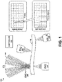
- Figure 1 is a conceptual illustration of an example system 100.
- the example system 100 includes an ultrasonic air-coupled transducer array 102, a plurality of receivers 104, 106, 108, 110, and a controller 112, which may be coupled together by a system bus, network, or other connection mechanism (not shown).
- the ultrasonic air-coupled transducer array 102 may be replaced by a single ultrasonic transducer.
- the system 100 of Figure 1 is described as including a transducer array, the example is not meant to be limiting.
- the transducer array 102 may include 300 transducers arranged to emit acoustic and/or ultrasound waves. In one embodiment, the transducer array 102 may be configured to emit primary ultrasound waves that interfere with each other. As an example, each of the transducers of the array may be configured to emit one of two or more fundamental frequency components that are multiples of each other (e.g., 40 kHz and 80 kHz; 50 kHz and 100 kHz, etc.).
- the transducer array 102 may include 300 transducers arranged to emit acoustic and/or ultrasound waves. In one embodiment, the transducer array 102 may be configured to emit primary ultrasound waves that interfere with each other. As an example, each of the transducers of the array may be configured to emit one of two or more fundamental frequency components that are multiples of each other (e.g., 40 kHz and 80 kHz; 50 kHz and 100 kHz, etc.).
- each of the fundamental frequency components may be emitted simultaneously in locked phase, such that interference between the primary ultrasound waves generates a plurality of frequency harmonics in the air.
- the plurality of frequency harmonics may range in frequency from a few hertz to multiple megahertz. The generation of these frequency harmonics can be explained by some of the non-linear effects taking place.
- a sine wave becomes more like a sawtooth waveform.
- the sawtooth waveform contains even and odd harmonics, with the second harmonic being twice the frequency and half the wavelength of the first harmonic, for instance.
- the generation of the frequency harmonics using a low frequency (e.g., kilohertz) primary ultrasound wave also contributes to a reduction in losses due to attenuation in the air.
- the frequency harmonics are generated in an interference field in the air at a point where the primary ultrasound waves are focused rather than emitted by a transducer.
- the high frequency harmonics do not have to travel through as much air as compared to a scenario in which a transducer emits high frequency waves. And as a result, the high frequency harmonics do not suffer from as much attenuation in the air as if they had been directly emitted by a transducer.
- the primary ultrasound waves may form an interference field that includes interference columns with standing wave patterns. This interference may be measurable by the receiver 104 positioned between the transducer array 102 and an object 114 under test.
- the standing wave pattern may include alternating regions of air compression and rarefaction, with ultrasound shock waves formed in the regions of compression.
- the primary ultrasound waves emitted by the transducer array 102 as well as the plurality of harmonics generated by the interference of the primary ultrasound waves may propagate throughout the object 114 in a variety of modes, such as longitudinal, shear, surface, and others.
- the propagation throughout the object 114 may, in turn, generate secondary ultrasound and/or acoustic waves.
- the plurality of receivers 104, 106, 108, 110 may be configured to receive the secondary ultrasound and/or acoustic waves emitted from the object 114 in various places around the object 114.
- one or more of the plurality of receivers 104, 106, 108, 110 may be air-coupled receivers.
- the plurality of receivers may, in turn, provide the received signals to the controller 112.
- the controller 112 may function to control the transducer array 102. For instance, the controller 112 may energize the transducers of the array to emit ultrasound waves. As another example, the controller 112 may direct and/or focus the transducers of the transducer array to adjust a position of an interference field. The controller 112 may also function to control the plurality of receivers 104, 106, 108, 110 and to process signals received from the plurality of receivers. The plurality of receivers 104, 106, 108, 110 may operate at multiple frequencies simultaneously. Thus, the controller 106 may be configured to process signals received from the plurality of receivers 104, 106, 108, 110 in the time domain, the frequency domain, or both.
- the controller 112 may include one or more processors and one or more memories.
- the controller 112 may be a computing device, such as a tablet computing device, laptop computing device, or desktop computing device.
- the transducer array 102 may emit primary ultrasound waves that interfere with each other in an interference field.
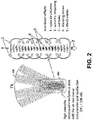
- Figure 2 is a conceptual illustration of an example interference field.
- Figure 2 illustrates non-linear effects that may occur due to interference between primary ultrasound waves emitted by the transducer array 102 of Figure 1 .
- the primary ultrasound waves may interfere within an interference area 202.
- the SPL may be greater than 130 dB.
- Figure 2 depicts the formation of such structures within the interference area 202.
- the structures, referred to herein as interference columns are similar to open air columns having a pattern of standing waves with alternating regions of air compression and rarefaction.
- the interference of the primary ultrasound waves in the interference area 202 may generate pronounced and steady airflow directed outward from the transducer.
- airflows are a phenomenon known as acoustic streaming.
- Acoustic streaming in air is explained as an airflow in the form of vortexes caused by high intensity sound waves.
- Figure 2 also depicts the presence of ultrasound shock waves within the interference area 202. As discussed in more detail below, the presence of the ultrasound shock waves may contribute to the formation of high frequency harmonics in the compression areas within the interference columns.
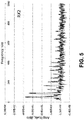
- Figures 3-6 illustrate example frequency measurements obtained using the example system 100 of Figure 1 in an example experiment.
- Figures 3-6 illustrate example frequency measurements obtained with the receivers 104, 106, 108, 110 of Figure 1 , respectively.
- the transducer array 102 included 300 40-kHz air-coupled transducers and was measured to produce a SPL of about 145 dB.
- the transducer array 102 was focused on the center of a carbon composite panel at a focus length of six inches.
- the carbon fiber panel was approximately 5 feet by 5 feet.
- the receivers 104, 106, 108, 110 were placed around the carbon fiber composite panel.
- receiver 104 was positioned in the interference field, facing the panel, at a distance of two inches from the panel; receiver 106 was positioned on the back side of the panel; receiver 108 was positioned on the front side of the panel at approximately one foot away from the interference field; and receiver 110 was positioned on the back side of the panel in an upper corner.
- the frequency measurements shown in Figure 3 indicate the presence of even and odd harmonics with frequencies as high as a few megahertz.
- Figure 7 illustrates example interference columns.
- Figure 7 is an image 700 of interference columns visualized with liquid nitrogen during an experiment.
- a piece of foam 702 loaded with liquid nitrogen was placed within the focus of a transducer array having 300 transducers (not shown).
- the fundamental frequency of the transducer array was measured to be about 42.363 kHz.
- the SPL was about 130 dB.
- the transducer array generated airflow directed outward from the transmitter array and in the form of vortexes.
- the airflow was measured to have a velocity of about 1.3 meters per second.
- the liquid nitrogen cooled the air, producing a fog 704.
- Fog forms when the difference between the air temperature and the dew point is less than 4° F.
- the room air temperature was about 73° F and the relative humidity was about 45%. These conditions correspond to a dew point of 50° F and a fog formation temperature of about 54° F.
- the fog 704 highlighted and revealed the interference columns by flowing into the interference columns. Peaks and troughs of the interference columns are visible in the image 700 due to the differences in the dew points in the neighboring areas. Based on image analysis of the image 700, the distances between the peaks and troughs of the fog 704 appeared to be equal and about 4 mm.
- the 4-mm distance is about one half wavelength of a 40 kHz ultrasound in air. In particular, the 4-mm distance corresponds to the ultrasound frequency of 42.368 kHz which is in good agreement with the measured frequency of the transducer array's first harmonic during the experiment, 42.363 kHz.
- the fog 704 was observed to be actually dragged into the interference columns, indicating the existence of areas of negative pressure as well as downstream and upstream vortexes in the airflow generated by the transducer array.
- Figure 8 illustrates example frequency measurements indicative of a plurality of frequency harmonics.
- Figure 8 illustrates frequency harmonics measured in another experiment.
- a transducer array having 300 transducers emitted primary ultrasound waves.
- the primary ultrasound waves had frequencies of either approximately 40 kHz or 80 kHz.
- Frequency measurements were done with a 300 kHz receiver initially placed in the focus of the transducer array and then moved further away from the transducer array in 0.1-inch increments.
- the receiver detected different numbers of harmonics in the areas of air compression and rarefaction. Specifically, in the areas of rarefaction (i.e., 0.3 inches and 0.5 inches in Figure 8 ), the received detected harmonics up to 1 MHz. On the other hand, in the areas of compression (i.e., 0.2 inches and 0.4 inches in Figure 8 ), the receiver detected harmonics up to 1 MHz as well as harmonics above 1 MHz. The average distance between the compression and rarefaction areas appeared to be within 0.16 - 0.20 inches. This same distance was measured and visualized with liquid nitrogen in the experiment described above with respect to Figure 7 .
- Figure 9 illustrates example oscillograms 902, 904 of an interference field measured with a receiver placed in a focus of a transducer array having 300 transducers.
- the left oscillogram 902 shows the ultrasound waveform when 9 watts are supplied to the transducer array (low power). At this power, the transducer array may generate harmonics below 500 kHz without generating any higher harmonics.
- the right oscillogram 904 shows the ultrasound waveform when 82 watts are supplied to the transducer array (high power).
- the right oscillogram 904 shows the sequence of one half wavelength of rarefaction, then one half wavelength of compression, then another half wavelength of rarefaction.
- the waveform is symmetrical with the total time sum equal to 25 microseconds which corresponds to a frequency of 40 kHz.
- the sequence becomes unsymmetrical, with a 2-microsecond steeper front 906 of the waveform and a 2-microsecond longer and gradual back 908 of the waveform.
- Such a transformation of the waveform between low power and high power is indicative of the formation of shock waves.
- Figure 10 illustrates an infrared image 1000 of an ultrasonic transducer array 1002 and its focus point 1004 during an example experiment.
- the interference field generated by the transducer 1002 may create a temperature gradient.
- the ultrasonic transducer 1002 was a transducer array having 300 transducers.
- the infrared image 1000 was taken with a black piece of foam as the background.
- the maximum temperature of the focus point was measured to be about 56° C. The increase in temperature at the focus point is indicative of the formation of ultrasound shock waves in the compression areas of the interference field.
- the formation of ultrasound shock waves contributes to a reduction in losses due to acoustic impedance mismatches between the air and a surface of an object.
- Shock waves change the properties of air dramatically, and the air essentially becomes a quasiliquid where the shock waves are formed.
- This quasiliquid may be in contact with a surface of an object under test and may have an acoustic impedance that is greater than the acoustic impedance of air.
- the acoustic impedance mismatch between the quasiliquid and a solid may be less than the acoustic impedance mismatch between air and a solid.
- Figure 11 is a conceptual illustration of an inspection of an object according to an example embodiment.
- Figure 11 shows changes in the frequencies measured by a receiver 1102 when a plastic cone 1104 is placed in close proximity to the focus point of a transducer array 1106. Without the plastic cone 1104 near the focus point of the transducer array 1106, the receiver 1102 detects a plurality of frequency harmonics, including frequency harmonics in the megahertz range.
- the plastic cone 1104 When the plastic cone 1104 is placed near the focus point of the transducer array 1106, the plastic cone 1104 changes the characteristics of the plurality of frequency harmonics. For example, the received power of some of the frequency harmonics is reduced due to the presence of the plastic cone 1104.
- the receiver 1102 may be configured to provide the signals received with and without the plastic cone 1104 to a controller (not shown). In this manner, the controller may determine one or more properties of the plastic cone by analyzing the received signals.
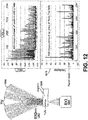
- Figures 12 and 13 are conceptual illustrations of an inspection of another object according to an example embodiment.
- Figures 12 and 13 show changes in the frequencies measured by receivers 1202 and 1204, respectively, which are indicative of the presence of a hole in a sample of polysulfide sealant 1206.
- the receivers 1202 and 1204 first measured ultrasound signals emitted from the sample of polysulfide sealant 1206 without a hole in the sample as a transducer array 1208 emitted primary ultrasound waves. Subsequently, a hole was added to the sample of polysulfide sealant 1206, and additional frequency measurements were obtained using the receivers 1202 and 1204.
- a graph 1310 of Figure 13 the difference (i.e., variance) between the frequency measurements obtained by the receiver 1204 with and without the hole in the sample of the polysulfide sealant 1206 is shown. As indicated in the graph 1310, there are noticeable changes in the frequency measurements obtained by the receiver 1202 with and without the hole in the sample of the polysulfide sealant 1206. The results depicted in the graph 1310 demonstrate that a controller or an operator may analyze frequency measurements determined using the receiver 1204 to determine that a sample has a hole.
- Figure 14 is a flowchart of an example method for nondestructive testing according to an example embodiment.
- Method 1400 shown in Figure 14 present an embodiment of a method that could be used with the system shown in Figure 1 , for example, or any of the systems disclosed herein.
- Example devices or systems may be used or configured to perform logical functions presented in Figure 14 .
- components of the devices and/or systems may be configured to perform the functions such that the components are actually configured and structured (with hardware and/or software) to enable such performance.
- components of the devices and/or systems may be arranged to be adapted to, capable of, or suited for performing the functions.
- Method 1400 may include one or more operations, functions, or actions as illustrated by one or more of blocks 1402-1406. Although these blocks are illustrated in a sequential order, these blocks may also be performed in parallel, and/or in a different order than those described herein. Also, the various blocks may be combined into fewer blocks, divided into additional blocks, and/or removed based upon the desired implementation.
- each block may represent a module, a segment, or a portion of program code, which includes one or more instructions executable by a processor for implementing specific logical functions or steps in the process.
- the program code may be stored on any type of computer readable medium or data storage, for example, such as a storage device including a disk or hard drive.
- the computer readable medium may include non-transitory computer readable medium or memory, for example, such as computer readable media that stores data for short periods of time like register memory, processor cache, and RAM.
- the computer readable media may also be any other volatile or non-volatile storage systems.
- the computer readable medium may be considered a tangible computer readable storage medium, for example.
- each block in Figure 14 may represent circuitry that is wired to perform the specific logical functions in the process.
- Alternative implementations are included within the scope of the example embodiments of the present disclosure in which functions may be executed out of order from that shown or discussed, including substantially concurrent or in reverse order, depending on the functionality involved, as would be understood by those skilled in the art.
- the method 1400 includes generating, using at least one air-coupled ultrasonic transducer, a plurality of frequency harmonics in an interference field in the air.
- a controller may cause a transducer array to emit primary ultrasound waves that interfere with each other in the air.
- the primary ultrasound waves may include frequency components that are multiples of each other, and the primary ultrasound waves may be emitted simultaneously.
- the primary ultrasound waves may generate a plurality of frequency harmonics.
- the controller may also adjust a position of the interference field.
- adjusting the position of the interference field may involve directing (e.g., electronically or mechanically steering) the primary ultrasound waves emitted by the ultrasonic transducer. Additionally or alternatively, adjusting the position of the interference field may involve focusing the ultrasonic transducer on the surface of an object under test.
- an operator or a robotic system may position the at least one air-coupled ultrasonic transducer within a predetermined distance of the object. For instance, the operator or robotic system may move the transducer such that it is focused on the surface of the object under test.
- the method 1400 includes receiving ultrasonic waves reflected from and generated in an object under test.
- a non-contact air-coupled ultrasonic receiver may receive the ultrasonic waves.
- the ultrasonic waves may be reflected from and generated in the object under test due to the generating of the plurality of frequency harmonics.
- the plurality of frequency harmonics may excite ultrasonic waves that are reflected from and generated in the object.
- the ultrasonic receiver may be located on a same side of the object as the at least one transducer or an opposite side of the object.
- the method 1400 includes analyzing, using a computing device, signals indicative of the ultrasonic waves in the time domain, frequency domain, or both, to determine at least one property of the object.
- the computing device may analyze the signals to determine whether the object includes a hole, indentation, or internal deformation (e.g., a delamination).
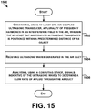
- Figure 15 is a flowchart of another example method for nondestructive testing according to an example embodiment.
- Method 1500 shown in Figure 15 present an embodiment of a method that could be used with the system 100 shown in Figure 1 , for example, or any of the systems disclosed herein.
- Method 1500 may include one or more operations, functions, or actions as illustrated by blocks 1502-1506 of the flowchart. Although the blocks are illustrated in a sequential order, these blocks may also be performed in parallel, and/or in a different order than those described herein. Also, the various blocks may be combined into fewer blocks, divided into additional blocks, and/or removed from the flowchart, based upon the desired implementation of the method 1500.
- Each block may represent a module, segment, or a portion of program code, which includes one or more instructions executable by a processor for implementing specific logical functions or steps in the process.
- each block in Figure 15 may represent circuitry that is wired to perform the specific logical functions in the process.
- the method 1500 includes generating, using at least one air-coupled ultrasonic transducer, a plurality of frequency harmonics in an interference field in the air.
- the at least one air-coupled ultrasonic transducer may be positioned within a predetermined distance of an air duct, such as an air duct of an aircraft structure.
- a controller may cause a transducer array to emit primary ultrasound waves that interfere with each other in the air.
- the primary ultrasound waves may include frequency components that are multiples of each other, and the primary ultrasound waves may be emitted simultaneously. When the primary ultrasound waves interfere with each other, the primary ultrasound waves may generate a plurality of frequency harmonics.
- the method 1500 includes responsive to the generating, receiving ultrasonic waves generated in the air duct.
- a non-contact air-coupled ultrasonic receiver may receive the ultrasonic waves.
- the ultrasonic waves may be generated in the air duct due to the generating of the plurality of frequency harmonics.
- the ultrasonic receiver may be located on a same side of the object as the at least one transducer or an opposite side of the object.
- the method 1500 includes analyzing, using a computing device, signals indicative of the ultrasonic waves to determine a flow rate of a fluid through the air duct.
- the controller may measure Doppler shifts of multiple frequencies to determine the flow rate. For instance, the controller may measure Doppler shifts in wavelengths of reflections from particles moving within the air duct. In this manner, the flow rate through the air duct may be estimated without removing the air duct and installing a flow meter.
Landscapes
- Physics & Mathematics (AREA)
- General Physics & Mathematics (AREA)
- Pathology (AREA)
- Life Sciences & Earth Sciences (AREA)
- Chemical & Material Sciences (AREA)
- Analytical Chemistry (AREA)
- Biochemistry (AREA)
- Health & Medical Sciences (AREA)
- Immunology (AREA)
- General Health & Medical Sciences (AREA)
- Acoustics & Sound (AREA)
- Engineering & Computer Science (AREA)
- Signal Processing (AREA)
- Mathematical Physics (AREA)
- Spectroscopy & Molecular Physics (AREA)
- Investigating Or Analyzing Materials By The Use Of Ultrasonic Waves (AREA)
Abstract
Description
- The present disclosure relates generally to ultrasonic systems and methods for inspecting objects and structures, and more particularly, to ultrasonic systems and methods for nondestructive testing using ultrasonic waves and air-coupled transducers.
- Ultrasonic testing is a subset of nondestructive testing that involves the propagation of ultrasound waves in an object or material under test. An example ultrasonic system may include an ultrasonic transducer that generates ultrasound waves which are transmitted into an object as the ultrasonic transducer is passed over a surface of the object or near the surface of the object. In a reflection (or pulse-echo) configuration, the ultrasonic transducer may also receive ultrasound waves that are reflected from interfaces and imperfections within the object and then provide the received ultrasound waves to a computing device for analysis. On the other hand, in an attenuation (or through-transmission) configuration, a receiver that is separate from the transducer (e.g., on an opposite side of the object) may receive the ultrasound waves after the ultrasound waves have travelled through the object and then provide the received ultrasound waves to a computing device for analysis.
- Within ultrasonic testing, ultrasonic systems may be classified as either liquid-coupled or air-coupled. In liquid-coupled systems, water or another liquid is used as a couplant between the transducer and the surface of the object. Conversely, in air-coupled systems, air or another gas is used as the couplant. Air-coupled systems may thus be considered non-contact systems, since no physical contact between the transducer and the object is required.
- In air-coupled systems, a significant amount of the energy of ultrasound waves may be lost due to attenuation in the air. The amount of attenuation in the air is proportional to the frequency of the ultrasound waves. Thus, as the frequency of the ultrasound waves increases, more energy is lost due to attenuation. Furthermore, in some examples, there may be a large difference in acoustic impedances between air and the surface material of an object. This difference in acoustic impedances may also cause a significant loss of energy. For instance, when an ultrasound wave traveling in air impinges on the boundary of solid material, more than 99.9% of the energy of the ultrasound wave may be reflected back due to the mismatch in acoustic impedances. Improvements are therefore desired.
- In one example, an ultrasonic system for nondestructive testing is provided. The ultrasonic system includes at least one air-coupled ultrasonic transducer configured to emit primary ultrasound waves that interfere with each other. The primary ultrasound waves include at least two fundamental frequency components that are multiples of each other and emitted simultaneously in locked phase. Further, the interference of the primary ultrasound waves generates a plurality of frequency harmonics in the air. The ultrasonic system also comprises at least one receiver configured to receive ultrasonic waves emitted from an object under test.
- In another example, a method for nondestructive testing is provided. The method includes generating, using at least one air-coupled ultrasonic transducer, a plurality of frequency harmonics in an interference field in the air. The method also includes receiving ultrasonic waves reflected from and generated in an object under test. The ultrasonic waves may be reflected from and generated in the object due to the generating of the plurality of frequency harmonics. And the method includes analyzing, using a computing device, signals indicative of the ultrasonic waves in the time domain, frequency domain, or both to determine at least one property of the object.
- In still another example, another method is provided. The method includes generating, using at least one air-coupled ultrasonic transducer, a plurality of frequency harmonics in an interference field in the air. The at least one air-coupled ultrasonic transducer is positioned within a predetermined distance of an air duct. The method also includes receiving ultrasonic waves generated in the air duct. The ultrasonic waves may be generated in the air duct to the generating of the plurality of frequency harmonics. And the method includes analyzing, using a computing device, signals indicative of the ultrasonic waves to determine a flow rate of a fluid through the air duct.
- The features, functions, and advantages that have been discussed can be achieved independently in various embodiments or may be combined in yet other embodiments further details of which can be seen with reference to the following description and figures.
- Clause A1. According to an aspect of the present disclosure there is provided an ultrasonic system for nondestructive testing, comprising: at least one air-coupled ultrasonic transducer configured to emit primary ultrasound waves that interfere with each other, wherein the primary ultrasound waves comprise at least two fundamental frequency components that are multiples of each other and emitted simultaneously in locked phase, and wherein the interference of the primary ultrasound waves generates a plurality of frequency harmonics in the air; at least one receiver configured to receive ultrasonic waves emitted from an object under test.
- Clause A2. The ultrasonic system of Clause A1, wherein the ultrasonic transducer is configured to emit primary ultrasound waves with a sound pressure level greater than 130dB, for example 145dB.
- Clause A3. The ultrasonic system of Clause A1 or A2, wherein the primary ultrasound waves form an interference field, and wherein the plurality of frequency harmonics is generated in the interference field.
- Clause A4. The ultrasonic system of Clause A3, wherein the interference field comprises interference columns with standing wave patterns generated in the air.
- Clause A5. The ultrasonic system of Clause A4, wherein the standing wave patterns comprise alternating regions of air compression and rarefaction, and wherein ultrasound shock waves are formed in the regions of compression.
- Clause A6. The ultrasonic system of any preceding clause, wherein the at least one air-coupled ultrasonic emitter comprises an array of air-coupled ultrasonic transducers.
- Clause A7. The ultrasonic system of any preceding clause, wherein the plurality of frequency harmonics comprise frequencies between 20 Hz and 20 MHz.
- Clause A8. The ultrasonic system of any preceding clause, wherein the at least two fundamental frequency components are below 100 kHz.
- Clause A9. The ultrasonic system of any preceding clause, wherein the at least one receiver comprises a non-contact air-coupled receiver.
- Clause A10. The ultrasonic system of any preceding clause, wherein the at least one receiver is configured to receive ultrasonic waves reflected from and generated in the object.
- Clause A11. The ultrasonic system of any preceding clause, wherein the at least one air-coupled ultrasonic transducer is positioned on a first side of the object, and wherein the at least one receiver comprises a first receiver positioned on the first side of the object and a second receiver positioned on a second side of the object that is opposite to the first side of the object.
- Clause A12. The ultrasonic system of any preceding clause, further comprising a controller, wherein the at least one receiver is further configured to provide signals indicative of the received ultrasonic waves to the controller, and wherein the controller is configured to analyze the signals in the time domain, frequency domain, or both.
- Clause A13. The ultrasonic system of any preceding clause, wherein the object comprises an air duct.
- Clause A14. According to an aspect of the present disclosure there is provided a method for nondestructive testing, comprising: generating, using at least one air-coupled ultrasonic transducer, a plurality of frequency harmonics in an interference field in the air; receiving ultrasonic waves reflected from and generated in an object under test, wherein the ultrasonic waves are reflected from and generated in the object due to the generating of the plurality of frequency harmonics; and analyzing, using a computing device, signals indicative of the ultrasonic waves in the time domain, frequency domain, or both to determine at least one property of the object.
- Clause A15. The method for nondestructive testing one of Clause A13, wherein generating the plurality of frequency harmonics in the interference field in the air comprises emitting primary ultrasound waves that interfere with each other, wherein the primary ultrasound waves comprises at least two fundamental frequency components that are multiples of each other and superimposed and, optionally, wherein the primary ultrasound waves have a sound pressure level greater than 130dB, for example 145dB.
- Clause A16. The method for nondestructive testing one of Clause A13 or A14, further comprising adjusting a position of the interference field.
- Clause A17. The method for nondestructive testing of any of Clauses A13-A15, further comprising positioning the at least one air-coupled ultrasonic transducer within a predetermined distance of the object.
- Clause A18. The method for nondestructive testing wherein receiving the ultrasonic waves comprises receiving ultrasonic waves from at least one non-contact air-coupled receiver positioned within a predetermined distance of the object.
- Clause A19. According to an aspect of the present disclosure there is provided a method comprising: generating, using at least one air-coupled ultrasonic transducer, a plurality of frequency harmonics in an interference field in the air, wherein the at least one air-coupled ultrasonic transducer is positioned within a predetermined distance of an air duct; receiving ultrasonic waves generated in the air duct, wherein the ultrasonic waves are generated in the air duct due to the generating of the plurality of frequency harmonics; and analyzing, using a computing device, signals indicative of the ultrasonic waves to determine a flow rate of a fluid through the air duct.
- Clause A20. The method for nondestructive testing of Clause A18, wherein generating the plurality of frequency harmonics in the interference field in the air comprises emitting primary ultrasound waves that interfere with each other, wherein the primary ultrasound waves comprises at least two fundamental frequency components that are multiples of each other and superimposed.
- Clause A21. The method for nondestructive testing of Clause A18 or A19 wherein receiving the ultrasonic waves comprises receiving ultrasonic waves from at least one non-contact air-coupled receiver.
- Clause A22. According to an aspect of the present disclosure there is provided a combination of a test object and an ultrasonic system for nondestructive testing, comprising: at least one air-coupled ultrasonic transducer configured to emit primary ultrasound waves that interfere with each other, wherein the primary ultrasound waves comprise at least two fundamental frequency components that are multiples of each other and emitted simultaneously in locked phase, and wherein the interference of the primary ultrasound waves generates a plurality of frequency harmonics in the air; at least one receiver configured to receive ultrasonic waves emitted from an object under test.
- Clause A23. The combination of a test object and an ultrasonic system of Clause A22, wherein the ultrasonic transducer is configured to emit primary ultrasound waves with a sound pressure level greater than 130dB, for example 145dB.
- Clause A24. The combination of a test object and an ultrasonic system of Clause A22 or A23, wherein the primary ultrasound waves form an interference field, and wherein the plurality of frequency harmonics is generated in the interference field.
- Clause A25. The combination of a test object and an ultrasonic system of Clause A24, wherein the interference field comprises interference columns with standing wave patterns generated in the air.
- Clause A26. The combination of a test object and an ultrasonic system of Clause A25, wherein the standing wave patterns comprise alternating regions of air compression and rarefaction, and wherein ultrasound shock waves are formed in the regions of compression.
- Clause A27. The combination of a test object and an ultrasonic system of an of Clauses A22 to A26, wherein the at least one air-coupled ultrasonic emitter comprises an array of air-coupled ultrasonic transducers.
- Clause A28. The combination of a test object and an ultrasonic system of any of Clauses A22 to A27, wherein the plurality of frequency harmonics comprise frequencies between 20 Hz and 20 MHz.
- Clause A29. The combination of a test object and an ultrasonic system of any of Clauses A22 to A28, wherein the at least two fundamental frequency components are below 100 kHz.
- Clause A30. The combination of a test object and an ultrasonic system of any of Clauses A22 to A29, wherein the at least one receiver comprises a non-contact air-coupled receiver.
- Clause A31. The combination of a test object and an ultrasonic system of any of Clauses A22 to A30, wherein the at least one receiver is configured to receive ultrasonic waves reflected from and generated in the object.
- Clause A32. The combination of a test object and an ultrasonic system of any of Clauses A22 to A31, wherein the at least one air-coupled ultrasonic transducer is positioned on a first side of the object, and wherein the at least one receiver comprises a first receiver positioned on the first side of the object and a second receiver positioned on a second side of the object that is opposite to the first side of the object.
- Clause A33. The combination of a test object and an ultrasonic system of any of Clauses A22 to A32, further comprising a controller, wherein the at least one receiver is further configured to provide signals indicative of the received ultrasonic waves to the controller, and wherein the controller is configured to analyze the signals in the time domain, frequency domain, or both.
- Clause A34. The combination of a test object and an ultrasonic system of any of Clauses A22 to A33, wherein the object comprises an air duct.
- The novel features believed characteristic of the illustrative embodiments are set forth in the appended claims. The illustrative embodiments, however, as well as a preferred mode of use, further objectives and descriptions thereof, will best be understood by reference to the following detailed description of an illustrative embodiment of the present disclosure when read in conjunction with the accompanying figures, wherein:
-
Figure 1 is a conceptual illustration of an example system according to an example embodiment. -
Figure 2 is a conceptual illustration of an example interference field according to an example embodiment. -
Figures 3-6 illustrate example frequency measurements obtained using the example system ofFigure 1 . -
Figure 7 illustrates example interference columns according to an example embodiment. -
Figure 8 illustrates example frequency measurements indicative of a plurality of frequency harmonics according to an example embodiment. -
Figure 9 illustrates example oscillograms of an interference field according to an example embodiment. -
Figure 10 illustrates an infrared image of an ultrasonic transducer array and its focus point according to an example embodiment. -
Figure 11 is a conceptual illustration of an inspection of an object according to an example embodiment. -
Figures 12 and13 are conceptual illustrations of an inspection of another object according to an example embodiment. -
Figure 14 is a flowchart of an example method for nondestructive testing according to an example embodiment. -
Figure 15 is a flowchart of another example method for nondestructive testing according to an example embodiment. - Disclosed embodiments will now be described more fully hereinafter with reference to the accompanying figures, in which some, but not all of the disclosed embodiments are shown. Indeed, several different embodiments may be provided and should not be construed as limited to the embodiments set forth herein. Rather, these embodiments are provided so that this disclosure will be thorough and complete and will fully convey the scope of the disclosure to those skilled in the art.
- Within examples, ultrasonic systems and methods for nondestructive testing are provided. In some examples, the systems and methods may facilitate non-contact nondestructive testing and characterization of materials and structures using ultrasound waves and air-coupled transducers. For instance, the systems and methods described herein may enable an inspector to evaluate an object and characterize any defects in the object such as holes or delaminations. Alternatively, the systems and methods described herein may enable an inspector to measure the flow rate of a fluid through a structure such as an air or water duct.
- As discussed above, in prior art air-coupled systems, a significant amount of the energy of ultrasound waves may be lost due to attenuation in the air and acoustic impedance mismatches between air and a surface of an object under test. Advantageously, the systems and methods described herein may significantly reduce losses due to attenuation in the air and acoustic impedance mismatches.
- In addition, as described herein, the example systems and methods may be used to characterize a variety of properties of complex three-dimensional shapes with better spatial resolution and/or a better signal-to-noise ratio than prior art systems. The example systems and methods may be used to generate simultaneously a well-structured pattern of even and odd harmonics in an entire audio and/or ultrasound region (e.g., from a few Hz to at least 20 MHz). This feature may enable inspecting objects in a shorter time frame as compared to inspecting objects using existing systems. Thus, the example systems and methods may be faster and more cost-effective than existing systems.
- In accordance with embodiments disclosed herein, an example system includes at least one air-coupled ultrasonic transducer and at least one receiver. The at least one air-coupled ultrasonic transducer may be configured to emit primary ultrasound waves that interfere with each other. In one example, the at least one air-coupled ultrasonic transducer may emit high power, low frequency ultrasound waves that cause the formation of high frequency harmonics. For instance, the at least one air-coupled ultrasonic transducer may simultaneously emit ultrasound waves at two or more frequencies that are multiples of each other (e.g., a first ultrasound wave at 40 kHz and a second ultrasound wave at 80 kHz). The transmitted ultrasound waves may interfere with each other in the air, and cause the formation of frequency harmonics (e.g., a third harmonic at 120 kHz, a fourth harmonic at 160 kHz, etc.). Thus, emitting the primary ultrasound waves may create a virtual transducer at a distance from the ultrasonic transducer that emits primary ultrasound waves as well as a plurality of frequency harmonics.
- When the primary ultrasound waves and the plurality of frequency harmonics reach an object under test, the ultrasound waves and frequency harmonics may excite secondary ultrasound and acoustic waves that are reflected from and generated in the object. These secondary waves may have characteristics that depend on and are indicative of the properties of the object. The secondary waves may be detected by the at least one receiver. In some instances, the at least one receiver may then provide signals indicative of the secondary waves to a controller that is configured to analyze the signals in the time domain and/or frequency domain. The controller may then determine one or more properties of the object using the received signals.
- In some instances, the primary ultrasound waves generated by the at least one ultrasonic transducer may form an interference field in which the plurality of frequency harmonics are generated. Further, the interference field may include interference columns with standing wave patterns.
- In one embodiment, the at least one ultrasonic transducer may be an array of ultrasonic transducers. In a similar manner, in some embodiments, the at least one receiver may include a set of receivers. For instance, the system may include a first receiver located on a first side of the object in which the at least one ultrasonic transducer is located and a second receiver located on an opposite side of the object.
- Various other features of the example systems discussed above, as well as methods for evaluating a surface of an object using these systems, are also described hereinafter with reference to the accompanying figures.
- Referring now to the figures,
Figure 1 is a conceptual illustration of anexample system 100. As shown inFigure 1 , theexample system 100 includes an ultrasonic air-coupledtransducer array 102, a plurality ofreceivers controller 112, which may be coupled together by a system bus, network, or other connection mechanism (not shown). - As discussed above, in some examples, the ultrasonic air-coupled
transducer array 102 may be replaced by a single ultrasonic transducer. Thus, although thesystem 100 ofFigure 1 is described as including a transducer array, the example is not meant to be limiting. - In one example, the
transducer array 102 may include 300 transducers arranged to emit acoustic and/or ultrasound waves. In one embodiment, thetransducer array 102 may be configured to emit primary ultrasound waves that interfere with each other. As an example, each of the transducers of the array may be configured to emit one of two or more fundamental frequency components that are multiples of each other (e.g., 40 kHz and 80 kHz; 50 kHz and 100 kHz, etc.). - Furthermore, each of the fundamental frequency components may be emitted simultaneously in locked phase, such that interference between the primary ultrasound waves generates a plurality of frequency harmonics in the air. The plurality of frequency harmonics may range in frequency from a few hertz to multiple megahertz. The generation of these frequency harmonics can be explained by some of the non-linear effects taking place.
- First, it is known that, as a sound wave of high intensity propagates in air, the waveform of the sound wave changes. The distortion of the waveform is caused by the air non-linearity and, as a result, additional frequencies are generated. Sound in air is longitudinal pressure waves that are oscillations of air compression and rarefaction. For a sound of relatively low intensity (typically below sound pressure level ("SPL") of 70 dB), air behaves a linear medium with equal rates of compression and rarefaction. With increasing SPL, air becomes non-linear and the rates of compression and rarefaction vary such that the rates are no longer equal. In particular, the compression portion begins traveling faster than the rarefaction portion. This results in a continuous distortion of the waveform as the wave propagates in air and, as a consequence, in the generation of new, higher frequencies. By way of example, a sine wave becomes more like a sawtooth waveform. The sawtooth waveform contains even and odd harmonics, with the second harmonic being twice the frequency and half the wavelength of the first harmonic, for instance.
- Secondly, when at least two high intensity ultrasound waves with different frequencies interfere with each other, their sum frequencies and difference frequencies may be generated because of the non-linearity of the air. This effect is known as the acoustical heterodyning process. Whether different frequencies are generated from two transducers or from a single one, the effect is the same. As an example, if the primary ultrasound waves are 40 kHz and 80 kHz, the interference of the waves, may result in the formation of the difference frequency, 40 kHz, and the sum frequency, 120 kHz, which is the third harmonic. As the power of the primary ultrasound waves increases, 4th, 5th, 6th, and more harmonics may be generated.
- The generation of the frequency harmonics using a low frequency (e.g., kilohertz) primary ultrasound wave also contributes to a reduction in losses due to attenuation in the air. The frequency harmonics are generated in an interference field in the air at a point where the primary ultrasound waves are focused rather than emitted by a transducer. As such, the high frequency harmonics do not have to travel through as much air as compared to a scenario in which a transducer emits high frequency waves. And as a result, the high frequency harmonics do not suffer from as much attenuation in the air as if they had been directly emitted by a transducer.
- In one example, the primary ultrasound waves may form an interference field that includes interference columns with standing wave patterns. This interference may be measurable by the
receiver 104 positioned between thetransducer array 102 and anobject 114 under test. As discussed further below, in some instances, the standing wave pattern may include alternating regions of air compression and rarefaction, with ultrasound shock waves formed in the regions of compression. - In practice, the primary ultrasound waves emitted by the
transducer array 102 as well as the plurality of harmonics generated by the interference of the primary ultrasound waves may propagate throughout theobject 114 in a variety of modes, such as longitudinal, shear, surface, and others. The propagation throughout theobject 114 may, in turn, generate secondary ultrasound and/or acoustic waves. The plurality ofreceivers object 114 in various places around theobject 114. In some examples, one or more of the plurality ofreceivers controller 112. - The
controller 112 may function to control thetransducer array 102. For instance, thecontroller 112 may energize the transducers of the array to emit ultrasound waves. As another example, thecontroller 112 may direct and/or focus the transducers of the transducer array to adjust a position of an interference field. Thecontroller 112 may also function to control the plurality ofreceivers receivers receivers - In one example, the
controller 112 may include one or more processors and one or more memories. For instance, thecontroller 112 may be a computing device, such as a tablet computing device, laptop computing device, or desktop computing device. - As discussed above, the
transducer array 102 may emit primary ultrasound waves that interfere with each other in an interference field.Figure 2 is a conceptual illustration of an example interference field. In particular,Figure 2 illustrates non-linear effects that may occur due to interference between primary ultrasound waves emitted by thetransducer array 102 ofFigure 1 . - As shown in
Figure 2 , in one embodiment, the primary ultrasound waves may interfere within aninterference area 202. Within theinterference area 202, the SPL may be greater than 130 dB. Applicants discovered that by superimposing high power ultrasonic waves having at least two fundamental frequency components that are multiples of each other, structures similar to open air columns with standing waves of multiple frequencies can be formed right in the open air (i.e., acoustic free field).Figure 2 depicts the formation of such structures within theinterference area 202. The structures, referred to herein as interference columns, are similar to open air columns having a pattern of standing waves with alternating regions of air compression and rarefaction. - As also shown in
Figure 2 , in some examples, the interference of the primary ultrasound waves in theinterference area 202 may generate pronounced and steady airflow directed outward from the transducer. Such airflows are a phenomenon known as acoustic streaming. Acoustic streaming in air is explained as an airflow in the form of vortexes caused by high intensity sound waves. -
Figure 2 also depicts the presence of ultrasound shock waves within theinterference area 202. As discussed in more detail below, the presence of the ultrasound shock waves may contribute to the formation of high frequency harmonics in the compression areas within the interference columns. -
Figures 3-6 illustrate example frequency measurements obtained using theexample system 100 ofFigure 1 in an example experiment. In particular,Figures 3-6 illustrate example frequency measurements obtained with thereceivers Figure 1 , respectively. In the experiment, thetransducer array 102 included 300 40-kHz air-coupled transducers and was measured to produce a SPL of about 145 dB. Thetransducer array 102 was focused on the center of a carbon composite panel at a focus length of six inches. The carbon fiber panel was approximately 5 feet by 5 feet. Thereceivers receiver 104 was positioned in the interference field, facing the panel, at a distance of two inches from the panel; receiver 106 was positioned on the back side of the panel; receiver 108 was positioned on the front side of the panel at approximately one foot away from the interference field; andreceiver 110 was positioned on the back side of the panel in an upper corner. The frequency measurements shown inFigure 3 , for example, indicate the presence of even and odd harmonics with frequencies as high as a few megahertz. -
Figure 7 illustrates example interference columns. In particular,Figure 7 is animage 700 of interference columns visualized with liquid nitrogen during an experiment. In the experiment, a piece offoam 702 loaded with liquid nitrogen was placed within the focus of a transducer array having 300 transducers (not shown). The fundamental frequency of the transducer array was measured to be about 42.363 kHz. Within the focus, the SPL was about 130 dB. At this SPL, the transducer array generated airflow directed outward from the transmitter array and in the form of vortexes. The airflow was measured to have a velocity of about 1.3 meters per second. - As shown in the
image 700, during the experiment, the liquid nitrogen cooled the air, producing afog 704. Fog forms when the difference between the air temperature and the dew point is less than 4° F. At the time of the experiment, the room air temperature was about 73° F and the relative humidity was about 45%. These conditions correspond to a dew point of 50° F and a fog formation temperature of about 54° F. - The
fog 704 highlighted and revealed the interference columns by flowing into the interference columns. Peaks and troughs of the interference columns are visible in theimage 700 due to the differences in the dew points in the neighboring areas. Based on image analysis of theimage 700, the distances between the peaks and troughs of thefog 704 appeared to be equal and about 4 mm. The 4-mm distance is about one half wavelength of a 40 kHz ultrasound in air. In particular, the 4-mm distance corresponds to the ultrasound frequency of 42.368 kHz which is in good agreement with the measured frequency of the transducer array's first harmonic during the experiment, 42.363 kHz. Furthermore, thefog 704 was observed to be actually dragged into the interference columns, indicating the existence of areas of negative pressure as well as downstream and upstream vortexes in the airflow generated by the transducer array. -
Figure 8 illustrates example frequency measurements indicative of a plurality of frequency harmonics. In particular,Figure 8 illustrates frequency harmonics measured in another experiment. During the experiment, a transducer array having 300 transducers emitted primary ultrasound waves. The primary ultrasound waves had frequencies of either approximately 40 kHz or 80 kHz. Frequency measurements were done with a 300 kHz receiver initially placed in the focus of the transducer array and then moved further away from the transducer array in 0.1-inch increments. - As shown in
Figure 8 , the receiver detected different numbers of harmonics in the areas of air compression and rarefaction. Specifically, in the areas of rarefaction (i.e., 0.3 inches and 0.5 inches inFigure 8 ), the received detected harmonics up to 1 MHz. On the other hand, in the areas of compression (i.e., 0.2 inches and 0.4 inches inFigure 8 ), the receiver detected harmonics up to 1 MHz as well as harmonics above 1 MHz. The average distance between the compression and rarefaction areas appeared to be within 0.16 - 0.20 inches. This same distance was measured and visualized with liquid nitrogen in the experiment described above with respect toFigure 7 . - As discussed above, the generation of the higher MHz harmonic in the air compression areas is believed to be caused by the formation of shock waves.
Figure 9 illustratesexample oscillograms - The
left oscillogram 902 shows the ultrasound waveform when 9 watts are supplied to the transducer array (low power). At this power, the transducer array may generate harmonics below 500 kHz without generating any higher harmonics. - The
right oscillogram 904 shows the ultrasound waveform when 82 watts are supplied to the transducer array (high power). Theright oscillogram 904 shows the sequence of one half wavelength of rarefaction, then one half wavelength of compression, then another half wavelength of rarefaction. At low power, the waveform is symmetrical with the total time sum equal to 25 microseconds which corresponds to a frequency of 40 kHz. Whereas, at high power, the sequence becomes unsymmetrical, with a 2-microsecondsteeper front 906 of the waveform and a 2-microsecond longer and gradual back 908 of the waveform. Such a transformation of the waveform between low power and high power is indicative of the formation of shock waves. -
Figure 10 illustrates aninfrared image 1000 of anultrasonic transducer array 1002 and itsfocus point 1004 during an example experiment. As discussed above, the interference field generated by thetransducer 1002 may create a temperature gradient. In the example experiment, theultrasonic transducer 1002 was a transducer array having 300 transducers. Theinfrared image 1000 was taken with a black piece of foam as the background. As shown inFigure 10 , the maximum temperature of the focus point was measured to be about 56° C. The increase in temperature at the focus point is indicative of the formation of ultrasound shock waves in the compression areas of the interference field. - Advantageously, the formation of ultrasound shock waves contributes to a reduction in losses due to acoustic impedance mismatches between the air and a surface of an object. Shock waves change the properties of air dramatically, and the air essentially becomes a quasiliquid where the shock waves are formed. This quasiliquid may be in contact with a surface of an object under test and may have an acoustic impedance that is greater than the acoustic impedance of air. In other words, the acoustic impedance mismatch between the quasiliquid and a solid may be less than the acoustic impedance mismatch between air and a solid. As a result, when shock waves are present, ultrasound waves directed towards an object under test cross a quasiliquid to solid boundary, rather than crossing an air to solid boundary, and a lesser amount of the energy of the ultrasound waves is reflected back towards the transducer.
-
Figure 11 is a conceptual illustration of an inspection of an object according to an example embodiment. In particular,Figure 11 shows changes in the frequencies measured by areceiver 1102 when aplastic cone 1104 is placed in close proximity to the focus point of atransducer array 1106. Without theplastic cone 1104 near the focus point of thetransducer array 1106, thereceiver 1102 detects a plurality of frequency harmonics, including frequency harmonics in the megahertz range. When theplastic cone 1104 is placed near the focus point of thetransducer array 1106, theplastic cone 1104 changes the characteristics of the plurality of frequency harmonics. For example, the received power of some of the frequency harmonics is reduced due to the presence of theplastic cone 1104. In some examples, thereceiver 1102 may be configured to provide the signals received with and without theplastic cone 1104 to a controller (not shown). In this manner, the controller may determine one or more properties of the plastic cone by analyzing the received signals. -
Figures 12 and13 are conceptual illustrations of an inspection of another object according to an example embodiment. In particular,Figures 12 and13 show changes in the frequencies measured byreceivers polysulfide sealant 1206. In order to obtain the frequency measurements presented inFigures 12 and13 , thereceivers polysulfide sealant 1206 without a hole in the sample as atransducer array 1208 emitted primary ultrasound waves. Subsequently, a hole was added to the sample ofpolysulfide sealant 1206, and additional frequency measurements were obtained using thereceivers - In
Figure 12 , and in particular in agraph 1210, the difference (i.e., variance) between the frequency measurements obtained by thereceiver 1202 with and without the hole in the sample of thepolysulfide sealant 1206 is shown. As indicated in thegraph 1210, there are noticeable changes in the frequency measurements obtained by thereceiver 1202 with and without the hole in the sample of thepolysulfide sealant 1206. The results depicted in thegraph 1210 demonstrate that a controller or an operator may analyze frequency measurements determined using thereceiver 1202 to determine that a sample has a hole. - Similarly, in a
graph 1310 ofFigure 13 , the difference (i.e., variance) between the frequency measurements obtained by thereceiver 1204 with and without the hole in the sample of thepolysulfide sealant 1206 is shown. As indicated in thegraph 1310, there are noticeable changes in the frequency measurements obtained by thereceiver 1202 with and without the hole in the sample of thepolysulfide sealant 1206. The results depicted in thegraph 1310 demonstrate that a controller or an operator may analyze frequency measurements determined using thereceiver 1204 to determine that a sample has a hole. -
Figure 14 is a flowchart of an example method for nondestructive testing according to an example embodiment.Method 1400 shown inFigure 14 present an embodiment of a method that could be used with the system shown inFigure 1 , for example, or any of the systems disclosed herein. Example devices or systems may be used or configured to perform logical functions presented inFigure 14 . In some instances, components of the devices and/or systems may be configured to perform the functions such that the components are actually configured and structured (with hardware and/or software) to enable such performance. In other examples, components of the devices and/or systems may be arranged to be adapted to, capable of, or suited for performing the functions.Method 1400 may include one or more operations, functions, or actions as illustrated by one or more of blocks 1402-1406. Although these blocks are illustrated in a sequential order, these blocks may also be performed in parallel, and/or in a different order than those described herein. Also, the various blocks may be combined into fewer blocks, divided into additional blocks, and/or removed based upon the desired implementation. - It should be understood that for this and other processes and methods disclosed herein, flowcharts show functionality and operation of one possible implementation of present embodiments. In this regard, each block may represent a module, a segment, or a portion of program code, which includes one or more instructions executable by a processor for implementing specific logical functions or steps in the process. The program code may be stored on any type of computer readable medium or data storage, for example, such as a storage device including a disk or hard drive. The computer readable medium may include non-transitory computer readable medium or memory, for example, such as computer readable media that stores data for short periods of time like register memory, processor cache, and RAM. The computer readable media may also be any other volatile or non-volatile storage systems. The computer readable medium may be considered a tangible computer readable storage medium, for example.
- In addition, each block in
Figure 14 may represent circuitry that is wired to perform the specific logical functions in the process. Alternative implementations are included within the scope of the example embodiments of the present disclosure in which functions may be executed out of order from that shown or discussed, including substantially concurrent or in reverse order, depending on the functionality involved, as would be understood by those skilled in the art. - Initially, at
block 1402, themethod 1400 includes generating, using at least one air-coupled ultrasonic transducer, a plurality of frequency harmonics in an interference field in the air. By way of example, a controller may cause a transducer array to emit primary ultrasound waves that interfere with each other in the air. The primary ultrasound waves may include frequency components that are multiples of each other, and the primary ultrasound waves may be emitted simultaneously. When the primary ultrasound waves interfere with each other, the primary ultrasound waves may generate a plurality of frequency harmonics. - In some examples, the controller may also adjust a position of the interference field. In one example, adjusting the position of the interference field may involve directing (e.g., electronically or mechanically steering) the primary ultrasound waves emitted by the ultrasonic transducer. Additionally or alternatively, adjusting the position of the interference field may involve focusing the ultrasonic transducer on the surface of an object under test. In some examples, an operator or a robotic system may position the at least one air-coupled ultrasonic transducer within a predetermined distance of the object. For instance, the operator or robotic system may move the transducer such that it is focused on the surface of the object under test.
- At
block 1404, themethod 1400 includes receiving ultrasonic waves reflected from and generated in an object under test. By way of example, a non-contact air-coupled ultrasonic receiver may receive the ultrasonic waves. In line with the discussion above, the ultrasonic waves may be reflected from and generated in the object under test due to the generating of the plurality of frequency harmonics. For instance, the plurality of frequency harmonics may excite ultrasonic waves that are reflected from and generated in the object. The ultrasonic receiver may be located on a same side of the object as the at least one transducer or an opposite side of the object. - At block 1406, the
method 1400 includes analyzing, using a computing device, signals indicative of the ultrasonic waves in the time domain, frequency domain, or both, to determine at least one property of the object. As one example, the computing device may analyze the signals to determine whether the object includes a hole, indentation, or internal deformation (e.g., a delamination). -
Figure 15 is a flowchart of another example method for nondestructive testing according to an example embodiment.Method 1500 shown inFigure 15 present an embodiment of a method that could be used with thesystem 100 shown inFigure 1 , for example, or any of the systems disclosed herein. -
Method 1500 may include one or more operations, functions, or actions as illustrated by blocks 1502-1506 of the flowchart. Although the blocks are illustrated in a sequential order, these blocks may also be performed in parallel, and/or in a different order than those described herein. Also, the various blocks may be combined into fewer blocks, divided into additional blocks, and/or removed from the flowchart, based upon the desired implementation of themethod 1500. Each block may represent a module, segment, or a portion of program code, which includes one or more instructions executable by a processor for implementing specific logical functions or steps in the process. In addition, each block inFigure 15 may represent circuitry that is wired to perform the specific logical functions in the process. - Initially, at
block 1502, themethod 1500 includes generating, using at least one air-coupled ultrasonic transducer, a plurality of frequency harmonics in an interference field in the air. The at least one air-coupled ultrasonic transducer may be positioned within a predetermined distance of an air duct, such as an air duct of an aircraft structure. In one example, a controller may cause a transducer array to emit primary ultrasound waves that interfere with each other in the air. The primary ultrasound waves may include frequency components that are multiples of each other, and the primary ultrasound waves may be emitted simultaneously. When the primary ultrasound waves interfere with each other, the primary ultrasound waves may generate a plurality of frequency harmonics. - At
block 1504, themethod 1500 includes responsive to the generating, receiving ultrasonic waves generated in the air duct. By way of example, a non-contact air-coupled ultrasonic receiver may receive the ultrasonic waves. In line with the discussion above, the ultrasonic waves may be generated in the air duct due to the generating of the plurality of frequency harmonics. The ultrasonic receiver may be located on a same side of the object as the at least one transducer or an opposite side of the object. - At
block 1506, themethod 1500 includes analyzing, using a computing device, signals indicative of the ultrasonic waves to determine a flow rate of a fluid through the air duct. In one example, the controller may measure Doppler shifts of multiple frequencies to determine the flow rate. For instance, the controller may measure Doppler shifts in wavelengths of reflections from particles moving within the air duct. In this manner, the flow rate through the air duct may be estimated without removing the air duct and installing a flow meter. - The description of the different advantageous arrangements has been presented for purposes of illustration and description, and is not intended to be exhaustive or limited to the embodiments in the form disclosed. Many modifications and variations will be apparent to those of ordinary skill in the art. Further, different advantageous embodiments may provide different advantages as compared to other advantageous embodiments. The embodiment or embodiments selected are chosen and described in order to best explain the principles of the embodiments, the practical application, and to enable others of ordinary skill in the art to understand the disclosure for various embodiments with various modifications as are suited to the particular use contemplated.
Claims (15)
- An ultrasonic system (100) for nondestructive testing, comprising:at least one air-coupled ultrasonic transducer (102) configured to emit primary ultrasound waves that interfere with each other, wherein the primary ultrasound waves comprise at least two fundamental frequency components that are multiples of each other and emitted simultaneously in locked phase, and wherein the interference of the primary ultrasound waves generates a plurality of frequency harmonics in the air;at least one receiver (104, 106, 108, 110) configured to receive ultrasonic waves emitted from an object under test.
- The ultrasonic system of claim 1, wherein the primary ultrasound waves form an interference field (202) and the plurality of frequency harmonics is generated in the interference field, and optionally, wherein the interference field comprises interference columns (700) with standing wave patterns generated in the air.
- The ultrasonic system of claim 1 or claim 2, wherein the ultrasonic transducer is configured to emit ultrasound waves with a sound pressure level greater than 130dB, for example 145dB.
- The ultrasonic system of any preceding claim, wherein the plurality of frequency harmonics comprise frequencies between 20 Hz and 20 MHz.
- The ultrasonic system of any preceding claim, wherein the at least two fundamental frequency components are below 100 kHz.
- The ultrasonic system of any preceding claim wherein the at least one receiver comprises a non-contact air-coupled receiver.
- The ultrasonic system of any preceding claim, wherein the at least one receiver is configured to receive ultrasonic waves reflected from and generated in the object.
- The ultrasonic system of any preceding claim:wherein the at least one air-coupled ultrasonic transducer is positioned on a first side of the object, andwherein the at least one receiver comprises a first receiver (104) positioned on the first side of the object and a second receiver (106) positioned on a second side of the object that is opposite to the first side of the object.
- The ultrasonic testing system of any preceding claim, further comprising a controller (112),
wherein the at least one receiver is further configured to provide signals indicative of the received ultrasonic waves to the controller, and
wherein the controller is configured to analyze the signals in the time domain, frequency domain, or both. - The ultrasonic testing system of any preceding claim, wherein the object comprises an air duct.
- A method (1400) for nondestructive testing, comprising:generating (1402), using at least one air-coupled ultrasonic transducer (102), a plurality of frequency harmonics in an interference field in the air;receiving (1404) ultrasonic waves reflected from and generated in an object under test, wherein the ultrasonic waves are reflected from and generated in the object due to the generating of the plurality of frequency harmonics; andanalyzing (1406), using a computing device (112), signals indicative of the ultrasonic waves in the time domain, frequency domain, or both to determine at least one property of the object.
- The method of claim 11, wherein generating the plurality of frequency harmonics in the interference field in the air comprises emitting primary ultrasound waves that interfere with each other, wherein the primary ultrasound waves comprises at least two fundamental frequency components that are multiples of each other and superimposed, and, optionally, wherein the primary ultrasound waves have a sound pressure level greater than 130dB, for example 145dB.
- The method of claims 11 or 12, further comprising adjusting a position of the interference field.
- The method of any of claims 11-13, further comprising positioning the at least one air-coupled ultrasonic transducer within a predetermined distance of the object.
- The method of any of claims 11-14, wherein receiving the ultrasonic waves comprises receiving ultrasonic waves from at least one non-contact air-coupled receiver (104, 106, 108, 110) positioned within a predetermined distance of the object.
Applications Claiming Priority (1)
| Application Number | Priority Date | Filing Date | Title |
|---|---|---|---|
| US14/941,203 US10151731B2 (en) | 2015-11-13 | 2015-11-13 | Ultrasonic system for nondestructive testing |
Publications (2)
| Publication Number | Publication Date |
|---|---|
| EP3168612A1 true EP3168612A1 (en) | 2017-05-17 |
| EP3168612B1 EP3168612B1 (en) | 2018-07-18 |
Family
ID=57241017
Family Applications (1)
| Application Number | Title | Priority Date | Filing Date |
|---|---|---|---|
| EP16197567.7A Active EP3168612B1 (en) | 2015-11-13 | 2016-11-07 | Ultrasonic system for nondestructive testing using nonlinear acoustics |
Country Status (7)
| Country | Link |
|---|---|
| US (1) | US10151731B2 (en) |
| EP (1) | EP3168612B1 (en) |
| JP (1) | JP6827298B2 (en) |
| CN (1) | CN106706751B (en) |
| BR (1) | BR102016025452B8 (en) |
| CA (1) | CA2941621C (en) |
| RU (1) | RU2658071C1 (en) |
Families Citing this family (12)
| Publication number | Priority date | Publication date | Assignee | Title |
|---|---|---|---|---|
| KR102106940B1 (en) * | 2018-07-20 | 2020-05-06 | 원광대학교 산학협력단 | Ultrasonic nondestructive inspection device using overtone vibrator |
| JP2020034391A (en) * | 2018-08-29 | 2020-03-05 | 株式会社日立製作所 | Ultrasonic inspection device and ultrasonic inspection method |
| WO2020110197A1 (en) * | 2018-11-27 | 2020-06-04 | 株式会社島津製作所 | Defect inspection apparatus and defect inspection method |
| CN110261486B (en) * | 2019-05-22 | 2024-06-11 | 杭州意能电力技术有限公司 | Ultrasonic probe capable of transmitting multi-frequency signals and its manufacturing process |
| CN110333287A (en) * | 2019-06-12 | 2019-10-15 | 西安交通大学 | A kind of bearing testers based on ultrasound |
| CN110346454B (en) * | 2019-07-24 | 2021-09-10 | 四川幔壳科技有限公司 | Concrete shallow surface layer ultrasonic surface wave detection method based on arrayed ultrasonic seismic sources |
| CN111783616B (en) * | 2020-06-28 | 2024-03-26 | 北京瓦特曼科技有限公司 | Nondestructive testing method based on data-driven self-learning |
| CN114052779A (en) * | 2020-08-06 | 2022-02-18 | 重庆海扶医疗科技股份有限公司 | Ultrasonic testing equipment |
| US11589177B2 (en) * | 2021-06-16 | 2023-02-21 | Jae Whan Kim | Apparatus for monitoring a space by using acoustic web |
| CN114354761B (en) * | 2022-01-11 | 2024-01-12 | 重庆医科大学 | Device and method for measuring loss of acoustic waveguide tube |
| CN115236205A (en) * | 2022-06-16 | 2022-10-25 | 北京航空航天大学 | Concrete pavement damage automatic scanning detection system based on air coupling ultrasound |
| CN116840291A (en) * | 2023-07-06 | 2023-10-03 | 中国石油大学(华东) | Ultrasonic and infrared thermal imaging integrated detection system and method sharing excitation source |
Citations (3)
| Publication number | Priority date | Publication date | Assignee | Title |
|---|---|---|---|---|
| EP0818773A2 (en) * | 1996-07-08 | 1998-01-14 | Lucent Technologies Inc. | Ground penetrating sonar |
| WO2000073781A1 (en) * | 1999-05-27 | 2000-12-07 | The Regents Of The University Of California | Apparatus and method for remote, noninvasive characterization of structures and fluids inside containers |
| US7839718B2 (en) * | 2008-07-02 | 2010-11-23 | Chevron U.S.A. Inc. | Device and method for generating a beam of acoustic energy from a borehole, and applications thereof |
Family Cites Families (25)
| Publication number | Priority date | Publication date | Assignee | Title |
|---|---|---|---|---|
| US2573536A (en) * | 1951-07-02 | 1951-10-30 | Jr Albert G Bodine | Engine detonation control by acoustic methods and apparatus |
| US4265122A (en) * | 1979-04-23 | 1981-05-05 | University Of Houston | Nondestructive testing apparatus and method utilizing time-domain ramp signals |
| US4327579A (en) * | 1979-08-29 | 1982-05-04 | Amf Incorporated | Ultrasonic tire testing apparatus |
| JPS61210944A (en) * | 1985-03-15 | 1986-09-19 | Hitachi Ltd | ultrasound microscope |
| CA2169307C (en) | 1994-12-12 | 2003-10-14 | David A. Hutchins | Non-contact characterization and inspection of materials using wideband air coupled ultrasound |
| US5679899A (en) | 1995-03-06 | 1997-10-21 | Holographics Inc. | Method and apparatus for non-destructive testing of structures |
| US5767407A (en) * | 1996-01-23 | 1998-06-16 | The Regents Of The University Of California | Noninvasive identification of fluids by swept-frequency acoustic interferometry |
| US5889870A (en) | 1996-07-17 | 1999-03-30 | American Technology Corporation | Acoustic heterodyne device and method |
| US6715354B2 (en) * | 1998-02-24 | 2004-04-06 | Massachusetts Institute Of Technology | Flaw detection system using acoustic doppler effect |
| US6367328B1 (en) * | 1999-07-12 | 2002-04-09 | Digital Wave Corporation | Noninvasive detection of corrosion, MIC, and foreign objects in fluid-filled containers using leaky guided ultrasonic waves |
| US6363788B1 (en) * | 2000-06-07 | 2002-04-02 | Digital Wave Corporation | Noninvasive detection of corrosion, mic, and foreign objects in containers, using guided ultrasonic waves |
| EP1238715A1 (en) | 2001-03-05 | 2002-09-11 | Prokic Miodrag | Multifrequency ultrasonic structural actuators |
| EP1883824A4 (en) * | 2005-05-04 | 2011-05-11 | Brandt Innovative Technologies Inc | Method and apparatus of detecting an object |
| RU2295124C1 (en) * | 2005-07-18 | 2007-03-10 | Федеральное государственное унитарное предприятие "Научно-исследовательский институт полимерных материалов" | Ultrasound control method |
| DE102006027422B4 (en) * | 2006-06-13 | 2014-02-06 | Continental Automotive Gmbh | Method and device for monitoring an exhaust gas turbocharger |
| CN201051092Y (en) * | 2007-06-15 | 2008-04-23 | 林俊明 | A sound and ultrasonic no damage detection device |
| US7963165B2 (en) | 2007-09-25 | 2011-06-21 | Los Alamos National Security, Llc | Non-contact feature detection using ultrasonic Lamb waves |
| US8176783B2 (en) * | 2007-09-25 | 2012-05-15 | Los Alamos National Security, Llc | Non-contact fluid characterization in containers using ultrasonic waves |
| WO2009099469A1 (en) * | 2008-02-07 | 2009-08-13 | California Institute Of Technology | Method and apparatus for nondestructive evaluation and monitoring of materials and structures |
| US8600702B2 (en) * | 2008-12-30 | 2013-12-03 | United States Pipe And Foundry Company, Llc | Non-destructive thickness measurement systems and methods |
| RU2408008C1 (en) * | 2009-07-22 | 2010-12-27 | Федеральное государственное унитарное предприятие "Научно-исследовательский институт полимерных материалов" | Method for ultrasonic inspection of articles |
| EP2745107A1 (en) | 2011-08-17 | 2014-06-25 | EMPA Eidgenössische Materialprüfungs- und Forschungsanstalt | Air coupled ultrasonic contactless method for non-destructive determination of defects in laminated structures |
| US9228878B2 (en) * | 2012-03-19 | 2016-01-05 | Advanced Energy Industries, Inc. | Dual beam non-contact displacement sensor |
| RU2504764C1 (en) * | 2012-09-28 | 2014-01-20 | Открытое акционерное общество "Научно-исследовательский институт полимерных материалов" | Method for ultrasonic inspection of items |
| KR20150118495A (en) * | 2014-04-14 | 2015-10-22 | 삼성전자주식회사 | ultrasonic probe, ultrasonic imaging apparatus and method for controlling a ultrasonic imaging apparatus |
-
2015
- 2015-11-13 US US14/941,203 patent/US10151731B2/en active Active
-
2016
- 2016-09-05 RU RU2016135796A patent/RU2658071C1/en active
- 2016-09-09 CA CA2941621A patent/CA2941621C/en active Active
- 2016-10-31 BR BR102016025452A patent/BR102016025452B8/en active IP Right Grant
- 2016-11-07 EP EP16197567.7A patent/EP3168612B1/en active Active
- 2016-11-07 JP JP2016217166A patent/JP6827298B2/en active Active
- 2016-11-11 CN CN201611002974.9A patent/CN106706751B/en active Active
Patent Citations (3)
| Publication number | Priority date | Publication date | Assignee | Title |
|---|---|---|---|---|
| EP0818773A2 (en) * | 1996-07-08 | 1998-01-14 | Lucent Technologies Inc. | Ground penetrating sonar |
| WO2000073781A1 (en) * | 1999-05-27 | 2000-12-07 | The Regents Of The University Of California | Apparatus and method for remote, noninvasive characterization of structures and fluids inside containers |
| US7839718B2 (en) * | 2008-07-02 | 2010-11-23 | Chevron U.S.A. Inc. | Device and method for generating a beam of acoustic energy from a borehole, and applications thereof |
Non-Patent Citations (4)
| Title |
|---|
| "Springer Handbook of Acoustics", 1 January 2007, SPRINGER, ISBN: 978-1-4939-0754-0, article WERNER LAUTERBORN ET AL: "Nonlinear Acoustics in Fluids", pages: 265 - 314, XP055340165 * |
| AYUMU OSUMI ET AL: "Basic study of non-contact measurement system for internal defect in solid materials using high-intensity aerial ultrasonic waves", SICE ANNUAL CONFERENCE (SICE), 2012 PROCEEDINGS OF, IEEE, 20 August 2012 (2012-08-20), pages 1120 - 1125, XP032259889, ISBN: 978-1-4673-2259-1 * |
| HATI A ET AL: "Phase-Lock Loops in Vibration Environments", PTTI 2009 - PROCEEDINGS OF THE 41ST ANNUAL PRECISE TIME AND TIME INTERVAL SYSTEMS AND APPLICATIONS MEETING, THE INSTITUTE OF NAVIGATION, 8551 RIXLEW LANESUITE 360MANASSAS, VA 20109, USA, 19 November 2009 (2009-11-19), pages 303 - 312, XP056011264 * |
| SOLODOV IGOR ET AL: "Nonlinear air-coupled emission: The signature to reveal and image microdamage in solid materials", APPLIED PHYSICS LETTERS, A I P PUBLISHING LLC, US, vol. 91, no. 25, 19 December 2007 (2007-12-19), pages 251910 - 251910, XP012104864, ISSN: 0003-6951, DOI: 10.1063/1.2827193 * |
Also Published As
| Publication number | Publication date |
|---|---|
| JP6827298B2 (en) | 2021-02-10 |
| US20170138907A1 (en) | 2017-05-18 |
| CA2941621A1 (en) | 2017-05-13 |
| CN106706751B (en) | 2021-07-23 |
| RU2658071C1 (en) | 2018-06-19 |
| BR102016025452B1 (en) | 2021-02-09 |
| US10151731B2 (en) | 2018-12-11 |
| CN106706751A (en) | 2017-05-24 |
| EP3168612B1 (en) | 2018-07-18 |
| BR102016025452A2 (en) | 2017-05-23 |
| BR102016025452B8 (en) | 2021-03-30 |
| CA2941621C (en) | 2021-09-21 |
| JP2017125838A (en) | 2017-07-20 |
Similar Documents
| Publication | Publication Date | Title |
|---|---|---|
| US10151731B2 (en) | Ultrasonic system for nondestructive testing | |
| Rahim et al. | Non-invasive imaging of liquid/gas flow using ultrasonic transmission-mode tomography | |
| CN110702785B (en) | Method and device for time-frequency domain modal decomposition and defect positioning of frequency dispersion Lamb wave polynomial | |
| Benstock et al. | The influence of surface roughness on ultrasonic thickness measurements | |
| Diligent et al. | Reflection of the s lamb mode from a flat bottom circular hole | |
| Jarvis et al. | Application of the distributed point source method to rough surface scattering and ultrasonic wall thickness measurement | |
| JP2009063372A (en) | Aerial ultrasonic flaw detector and detection method | |
| CN108872393A (en) | Structural fatigue direction of check detection non-linear ultrasonic frequency mixing method | |
| CN107576730A (en) | A kind of method of normal probe measurement workpiece transverse wave velocity | |
| JP2011117878A (en) | Adhesion evaluation device and method | |
| JP2015125008A (en) | Ultrasonic flaw detection system and control method of ultrasonic flaw detection system | |
| Rahiman et al. | Modelling ultrasonic sensor for gas bubble profiles characterization of chemical column | |
| Chapuis et al. | Excitation and focusing of Lamb waves in a multilayered anisotropic plate | |
| JP5846367B2 (en) | Flaw detection method and flaw detection apparatus for welds using TOFD method | |
| Fromme et al. | Directivity of guided ultrasonic wave scattering at notches and cracks | |
| Meng et al. | Validation of zero-group-velocity feature guided waves in a welded joint | |
| Draudvilienė et al. | Validation of dispersion curve reconstruction techniques for the A0 and S0 modes of Lamb waves | |
| CN203117167U (en) | Ultrasonic detector for road steel bridge | |
| CN113960160A (en) | Damage detection method and device based on ultrasonic Lamb wave compact array | |
| Xiao et al. | Prediction of flat-bottom hole signals received by a spherically focused transducer for an ultrasonic pulse echo immersion testing | |
| Wang et al. | Measurement of focused ultrasonic fields using a scanning laser vibrometer | |
| Simonetti et al. | Ultrasonic computerized tomography for continuous monitoring of corrosion and erosion damage in pipelines | |
| JP2014044123A (en) | Contact interface detection device | |
| Xu et al. | Segmental search method for ultrasonic inspection of a wedge dual-layer medium using full matrix capture | |
| Gong et al. | Effect of surface roughness on laser ultrasonic guided wave defect detection for aluminum alloy plate |
Legal Events
| Date | Code | Title | Description |
|---|---|---|---|
| PUAI | Public reference made under article 153(3) epc to a published international application that has entered the european phase |
Free format text: ORIGINAL CODE: 0009012 |
|
| 17P | Request for examination filed |
Effective date: 20161107 |
|
| AK | Designated contracting states |
Kind code of ref document: A1 Designated state(s): AL AT BE BG CH CY CZ DE DK EE ES FI FR GB GR HR HU IE IS IT LI LT LU LV MC MK MT NL NO PL PT RO RS SE SI SK SM TR |
|
| AX | Request for extension of the european patent |
Extension state: BA ME |
|
| RIN1 | Information on inventor provided before grant (corrected) |
Inventor name: LEWIS, DENNIS M Inventor name: PONOMAREV, SERGEY G Inventor name: COOPER, WAYNE |
|
| RIC1 | Information provided on ipc code assigned before grant |
Ipc: G01S 7/52 20060101ALI20171207BHEP Ipc: G01N 29/036 20060101AFI20171207BHEP Ipc: G01N 29/04 20060101ALI20171207BHEP Ipc: G01N 29/44 20060101ALI20171207BHEP Ipc: G01N 29/11 20060101ALI20171207BHEP Ipc: G01N 29/46 20060101ALI20171207BHEP Ipc: G01N 29/34 20060101ALI20171207BHEP Ipc: G01N 29/12 20060101ALI20171207BHEP |
|
| GRAJ | Information related to disapproval of communication of intention to grant by the applicant or resumption of examination proceedings by the epo deleted |
Free format text: ORIGINAL CODE: EPIDOSDIGR1 |
|
| GRAP | Despatch of communication of intention to grant a patent |
Free format text: ORIGINAL CODE: EPIDOSNIGR1 |
|
| INTG | Intention to grant announced |
Effective date: 20180201 |
|
| GRAS | Grant fee paid |
Free format text: ORIGINAL CODE: EPIDOSNIGR3 |
|
| GRAA | (expected) grant |
Free format text: ORIGINAL CODE: 0009210 |
|
| AK | Designated contracting states |
Kind code of ref document: B1 Designated state(s): AL AT BE BG CH CY CZ DE DK EE ES FI FR GB GR HR HU IE IS IT LI LT LU LV MC MK MT NL NO PL PT RO RS SE SI SK SM TR |
|
| REG | Reference to a national code |
Ref country code: GB Ref legal event code: FG4D |
|
| REG | Reference to a national code |
Ref country code: CH Ref legal event code: EP Ref country code: CH Ref legal event code: NV Representative=s name: KIRKER AND CIE S.A., CH |
|
| REG | Reference to a national code |
Ref country code: IE Ref legal event code: FG4D |
|
| REG | Reference to a national code |
Ref country code: AT Ref legal event code: REF Ref document number: 1019903 Country of ref document: AT Kind code of ref document: T Effective date: 20180815 |
|
| REG | Reference to a national code |
Ref country code: DE Ref legal event code: R096 Ref document number: 602016004128 Country of ref document: DE |
|
| REG | Reference to a national code |
Ref country code: NL Ref legal event code: MP Effective date: 20180718 |
|
| REG | Reference to a national code |
Ref country code: LT Ref legal event code: MG4D |
|
| REG | Reference to a national code |
Ref country code: AT Ref legal event code: MK05 Ref document number: 1019903 Country of ref document: AT Kind code of ref document: T Effective date: 20180718 |
|
| PG25 | Lapsed in a contracting state [announced via postgrant information from national office to epo] |
Ref country code: NL Free format text: LAPSE BECAUSE OF FAILURE TO SUBMIT A TRANSLATION OF THE DESCRIPTION OR TO PAY THE FEE WITHIN THE PRESCRIBED TIME-LIMIT Effective date: 20180718 |
|
| PG25 | Lapsed in a contracting state [announced via postgrant information from national office to epo] |
Ref country code: LT Free format text: LAPSE BECAUSE OF FAILURE TO SUBMIT A TRANSLATION OF THE DESCRIPTION OR TO PAY THE FEE WITHIN THE PRESCRIBED TIME-LIMIT Effective date: 20180718 Ref country code: PL Free format text: LAPSE BECAUSE OF FAILURE TO SUBMIT A TRANSLATION OF THE DESCRIPTION OR TO PAY THE FEE WITHIN THE PRESCRIBED TIME-LIMIT Effective date: 20180718 Ref country code: IS Free format text: LAPSE BECAUSE OF FAILURE TO SUBMIT A TRANSLATION OF THE DESCRIPTION OR TO PAY THE FEE WITHIN THE PRESCRIBED TIME-LIMIT Effective date: 20181118 Ref country code: FI Free format text: LAPSE BECAUSE OF FAILURE TO SUBMIT A TRANSLATION OF THE DESCRIPTION OR TO PAY THE FEE WITHIN THE PRESCRIBED TIME-LIMIT Effective date: 20180718 Ref country code: RS Free format text: LAPSE BECAUSE OF FAILURE TO SUBMIT A TRANSLATION OF THE DESCRIPTION OR TO PAY THE FEE WITHIN THE PRESCRIBED TIME-LIMIT Effective date: 20180718 Ref country code: NO Free format text: LAPSE BECAUSE OF FAILURE TO SUBMIT A TRANSLATION OF THE DESCRIPTION OR TO PAY THE FEE WITHIN THE PRESCRIBED TIME-LIMIT Effective date: 20181018 Ref country code: BG Free format text: LAPSE BECAUSE OF FAILURE TO SUBMIT A TRANSLATION OF THE DESCRIPTION OR TO PAY THE FEE WITHIN THE PRESCRIBED TIME-LIMIT Effective date: 20181018 Ref country code: AT Free format text: LAPSE BECAUSE OF FAILURE TO SUBMIT A TRANSLATION OF THE DESCRIPTION OR TO PAY THE FEE WITHIN THE PRESCRIBED TIME-LIMIT Effective date: 20180718 Ref country code: GR Free format text: LAPSE BECAUSE OF FAILURE TO SUBMIT A TRANSLATION OF THE DESCRIPTION OR TO PAY THE FEE WITHIN THE PRESCRIBED TIME-LIMIT Effective date: 20181019 Ref country code: SE Free format text: LAPSE BECAUSE OF FAILURE TO SUBMIT A TRANSLATION OF THE DESCRIPTION OR TO PAY THE FEE WITHIN THE PRESCRIBED TIME-LIMIT Effective date: 20180718 |
|
| PG25 | Lapsed in a contracting state [announced via postgrant information from national office to epo] |
Ref country code: HR Free format text: LAPSE BECAUSE OF FAILURE TO SUBMIT A TRANSLATION OF THE DESCRIPTION OR TO PAY THE FEE WITHIN THE PRESCRIBED TIME-LIMIT Effective date: 20180718 Ref country code: LV Free format text: LAPSE BECAUSE OF FAILURE TO SUBMIT A TRANSLATION OF THE DESCRIPTION OR TO PAY THE FEE WITHIN THE PRESCRIBED TIME-LIMIT Effective date: 20180718 Ref country code: AL Free format text: LAPSE BECAUSE OF FAILURE TO SUBMIT A TRANSLATION OF THE DESCRIPTION OR TO PAY THE FEE WITHIN THE PRESCRIBED TIME-LIMIT Effective date: 20180718 |
|
| REG | Reference to a national code |
Ref country code: DE Ref legal event code: R097 Ref document number: 602016004128 Country of ref document: DE |
|
| PG25 | Lapsed in a contracting state [announced via postgrant information from national office to epo] |
Ref country code: CZ Free format text: LAPSE BECAUSE OF FAILURE TO SUBMIT A TRANSLATION OF THE DESCRIPTION OR TO PAY THE FEE WITHIN THE PRESCRIBED TIME-LIMIT Effective date: 20180718 Ref country code: IT Free format text: LAPSE BECAUSE OF FAILURE TO SUBMIT A TRANSLATION OF THE DESCRIPTION OR TO PAY THE FEE WITHIN THE PRESCRIBED TIME-LIMIT Effective date: 20180718 Ref country code: EE Free format text: LAPSE BECAUSE OF FAILURE TO SUBMIT A TRANSLATION OF THE DESCRIPTION OR TO PAY THE FEE WITHIN THE PRESCRIBED TIME-LIMIT Effective date: 20180718 Ref country code: ES Free format text: LAPSE BECAUSE OF FAILURE TO SUBMIT A TRANSLATION OF THE DESCRIPTION OR TO PAY THE FEE WITHIN THE PRESCRIBED TIME-LIMIT Effective date: 20180718 Ref country code: RO Free format text: LAPSE BECAUSE OF FAILURE TO SUBMIT A TRANSLATION OF THE DESCRIPTION OR TO PAY THE FEE WITHIN THE PRESCRIBED TIME-LIMIT Effective date: 20180718 |
|
| PLBE | No opposition filed within time limit |
Free format text: ORIGINAL CODE: 0009261 |
|
| STAA | Information on the status of an ep patent application or granted ep patent |
Free format text: STATUS: NO OPPOSITION FILED WITHIN TIME LIMIT |
|
| PG25 | Lapsed in a contracting state [announced via postgrant information from national office to epo] |
Ref country code: SM Free format text: LAPSE BECAUSE OF FAILURE TO SUBMIT A TRANSLATION OF THE DESCRIPTION OR TO PAY THE FEE WITHIN THE PRESCRIBED TIME-LIMIT Effective date: 20180718 Ref country code: DK Free format text: LAPSE BECAUSE OF FAILURE TO SUBMIT A TRANSLATION OF THE DESCRIPTION OR TO PAY THE FEE WITHIN THE PRESCRIBED TIME-LIMIT Effective date: 20180718 Ref country code: SK Free format text: LAPSE BECAUSE OF FAILURE TO SUBMIT A TRANSLATION OF THE DESCRIPTION OR TO PAY THE FEE WITHIN THE PRESCRIBED TIME-LIMIT Effective date: 20180718 |
|
| 26N | No opposition filed |
Effective date: 20190423 |
|
| PG25 | Lapsed in a contracting state [announced via postgrant information from national office to epo] |
Ref country code: LU Free format text: LAPSE BECAUSE OF NON-PAYMENT OF DUE FEES Effective date: 20181107 Ref country code: MC Free format text: LAPSE BECAUSE OF FAILURE TO SUBMIT A TRANSLATION OF THE DESCRIPTION OR TO PAY THE FEE WITHIN THE PRESCRIBED TIME-LIMIT Effective date: 20180718 |
|
| REG | Reference to a national code |
Ref country code: BE Ref legal event code: MM Effective date: 20181130 |
|
| REG | Reference to a national code |
Ref country code: IE Ref legal event code: MM4A |
|
| PG25 | Lapsed in a contracting state [announced via postgrant information from national office to epo] |
Ref country code: SI Free format text: LAPSE BECAUSE OF FAILURE TO SUBMIT A TRANSLATION OF THE DESCRIPTION OR TO PAY THE FEE WITHIN THE PRESCRIBED TIME-LIMIT Effective date: 20180718 |
|
| PG25 | Lapsed in a contracting state [announced via postgrant information from national office to epo] |
Ref country code: IE Free format text: LAPSE BECAUSE OF NON-PAYMENT OF DUE FEES Effective date: 20181107 |
|
| PG25 | Lapsed in a contracting state [announced via postgrant information from national office to epo] |
Ref country code: BE Free format text: LAPSE BECAUSE OF NON-PAYMENT OF DUE FEES Effective date: 20181130 |
|
| REG | Reference to a national code |
Ref country code: DE Ref legal event code: R082 Ref document number: 602016004128 Country of ref document: DE Representative=s name: MAIER, LL.M., MICHAEL C., DE Ref country code: DE Ref legal event code: R082 Ref document number: 602016004128 Country of ref document: DE Representative=s name: BOULT WADE TENNANT LLP, DE |
|
| PG25 | Lapsed in a contracting state [announced via postgrant information from national office to epo] |
Ref country code: MT Free format text: LAPSE BECAUSE OF NON-PAYMENT OF DUE FEES Effective date: 20181107 |
|
| REG | Reference to a national code |
Ref country code: DE Ref legal event code: R082 Ref document number: 602016004128 Country of ref document: DE Representative=s name: BOULT WADE TENNANT LLP, DE |
|
| PG25 | Lapsed in a contracting state [announced via postgrant information from national office to epo] |
Ref country code: TR Free format text: LAPSE BECAUSE OF FAILURE TO SUBMIT A TRANSLATION OF THE DESCRIPTION OR TO PAY THE FEE WITHIN THE PRESCRIBED TIME-LIMIT Effective date: 20180718 |
|
| PG25 | Lapsed in a contracting state [announced via postgrant information from national office to epo] |
Ref country code: PT Free format text: LAPSE BECAUSE OF FAILURE TO SUBMIT A TRANSLATION OF THE DESCRIPTION OR TO PAY THE FEE WITHIN THE PRESCRIBED TIME-LIMIT Effective date: 20180718 |
|
| PG25 | Lapsed in a contracting state [announced via postgrant information from national office to epo] |
Ref country code: CY Free format text: LAPSE BECAUSE OF FAILURE TO SUBMIT A TRANSLATION OF THE DESCRIPTION OR TO PAY THE FEE WITHIN THE PRESCRIBED TIME-LIMIT Effective date: 20180718 Ref country code: HU Free format text: LAPSE BECAUSE OF FAILURE TO SUBMIT A TRANSLATION OF THE DESCRIPTION OR TO PAY THE FEE WITHIN THE PRESCRIBED TIME-LIMIT; INVALID AB INITIO Effective date: 20161107 Ref country code: MK Free format text: LAPSE BECAUSE OF NON-PAYMENT OF DUE FEES Effective date: 20180718 |
|
| P01 | Opt-out of the competence of the unified patent court (upc) registered |
Effective date: 20230516 |
|
| REG | Reference to a national code |
Ref country code: CH Ref legal event code: U11 Free format text: ST27 STATUS EVENT CODE: U-0-0-U10-U11 (AS PROVIDED BY THE NATIONAL OFFICE) Effective date: 20251201 |
|
| PGFP | Annual fee paid to national office [announced via postgrant information from national office to epo] |
Ref country code: DE Payment date: 20251128 Year of fee payment: 10 |
|
| PGFP | Annual fee paid to national office [announced via postgrant information from national office to epo] |
Ref country code: GB Payment date: 20251127 Year of fee payment: 10 |
|
| PGFP | Annual fee paid to national office [announced via postgrant information from national office to epo] |
Ref country code: FR Payment date: 20251125 Year of fee payment: 10 |
|
| PGFP | Annual fee paid to national office [announced via postgrant information from national office to epo] |
Ref country code: CH Payment date: 20251201 Year of fee payment: 10 |