EP3168588A1 - A system and method for applying a tensile load to a component - Google Patents
A system and method for applying a tensile load to a component Download PDFInfo
- Publication number
- EP3168588A1 EP3168588A1 EP16194302.2A EP16194302A EP3168588A1 EP 3168588 A1 EP3168588 A1 EP 3168588A1 EP 16194302 A EP16194302 A EP 16194302A EP 3168588 A1 EP3168588 A1 EP 3168588A1
- Authority
- EP
- European Patent Office
- Prior art keywords
- tubular member
- end portion
- divergent conical
- catcher rod
- conical portion
- Prior art date
- Legal status (The legal status is an assumption and is not a legal conclusion. Google has not performed a legal analysis and makes no representation as to the accuracy of the status listed.)
- Withdrawn
Links
- 238000000034 method Methods 0.000 title claims description 13
- 238000007689 inspection Methods 0.000 claims description 8
- 230000007246 mechanism Effects 0.000 claims description 5
- 230000001681 protective effect Effects 0.000 abstract 1
- 230000006835 compression Effects 0.000 description 9
- 238000007906 compression Methods 0.000 description 9
- 238000012986 modification Methods 0.000 description 2
- 230000004048 modification Effects 0.000 description 2
- 230000008569 process Effects 0.000 description 2
- 238000010521 absorption reaction Methods 0.000 description 1
- 230000007547 defect Effects 0.000 description 1
- 230000000694 effects Effects 0.000 description 1
- 239000012530 fluid Substances 0.000 description 1
- 230000003993 interaction Effects 0.000 description 1
- 230000021715 photosynthesis, light harvesting Effects 0.000 description 1
- 238000004088 simulation Methods 0.000 description 1
Images

Classifications
-
- F—MECHANICAL ENGINEERING; LIGHTING; HEATING; WEAPONS; BLASTING
- F01—MACHINES OR ENGINES IN GENERAL; ENGINE PLANTS IN GENERAL; STEAM ENGINES
- F01D—NON-POSITIVE DISPLACEMENT MACHINES OR ENGINES, e.g. STEAM TURBINES
- F01D25/00—Component parts, details, or accessories, not provided for in, or of interest apart from, other groups
- F01D25/28—Supporting or mounting arrangements, e.g. for turbine casing
- F01D25/285—Temporary support structures, e.g. for testing, assembling, installing, repairing; Assembly methods using such structures
-
- F—MECHANICAL ENGINEERING; LIGHTING; HEATING; WEAPONS; BLASTING
- F01—MACHINES OR ENGINES IN GENERAL; ENGINE PLANTS IN GENERAL; STEAM ENGINES
- F01D—NON-POSITIVE DISPLACEMENT MACHINES OR ENGINES, e.g. STEAM TURBINES
- F01D21/00—Shutting-down of machines or engines, e.g. in emergency; Regulating, controlling, or safety means not otherwise provided for
- F01D21/003—Arrangements for testing or measuring
-
- F—MECHANICAL ENGINEERING; LIGHTING; HEATING; WEAPONS; BLASTING
- F01—MACHINES OR ENGINES IN GENERAL; ENGINE PLANTS IN GENERAL; STEAM ENGINES
- F01D—NON-POSITIVE DISPLACEMENT MACHINES OR ENGINES, e.g. STEAM TURBINES
- F01D5/00—Blades; Blade-carrying members; Heating, heat-insulating, cooling or antivibration means on the blades or the members
- F01D5/02—Blade-carrying members, e.g. rotors
-
- F—MECHANICAL ENGINEERING; LIGHTING; HEATING; WEAPONS; BLASTING
- F04—POSITIVE - DISPLACEMENT MACHINES FOR LIQUIDS; PUMPS FOR LIQUIDS OR ELASTIC FLUIDS
- F04D—NON-POSITIVE-DISPLACEMENT PUMPS
- F04D27/00—Control, e.g. regulation, of pumps, pumping installations or pumping systems specially adapted for elastic fluids
- F04D27/001—Testing thereof; Determination or simulation of flow characteristics; Stall or surge detection, e.g. condition monitoring
-
- F—MECHANICAL ENGINEERING; LIGHTING; HEATING; WEAPONS; BLASTING
- F04—POSITIVE - DISPLACEMENT MACHINES FOR LIQUIDS; PUMPS FOR LIQUIDS OR ELASTIC FLUIDS
- F04D—NON-POSITIVE-DISPLACEMENT PUMPS
- F04D29/00—Details, component parts, or accessories
- F04D29/26—Rotors specially for elastic fluids
- F04D29/32—Rotors specially for elastic fluids for axial flow pumps
- F04D29/321—Rotors specially for elastic fluids for axial flow pumps for axial flow compressors
-
- F—MECHANICAL ENGINEERING; LIGHTING; HEATING; WEAPONS; BLASTING
- F04—POSITIVE - DISPLACEMENT MACHINES FOR LIQUIDS; PUMPS FOR LIQUIDS OR ELASTIC FLUIDS
- F04D—NON-POSITIVE-DISPLACEMENT PUMPS
- F04D29/00—Details, component parts, or accessories
- F04D29/60—Mounting; Assembling; Disassembling
- F04D29/64—Mounting; Assembling; Disassembling of axial pumps
- F04D29/644—Mounting; Assembling; Disassembling of axial pumps especially adapted for elastic fluid pumps
-
- G—PHYSICS
- G01—MEASURING; TESTING
- G01M—TESTING STATIC OR DYNAMIC BALANCE OF MACHINES OR STRUCTURES; TESTING OF STRUCTURES OR APPARATUS, NOT OTHERWISE PROVIDED FOR
- G01M1/00—Testing static or dynamic balance of machines or structures
- G01M1/02—Details of balancing machines or devices
- G01M1/04—Adaptation of bearing support assemblies for receiving the body to be tested
-
- F—MECHANICAL ENGINEERING; LIGHTING; HEATING; WEAPONS; BLASTING
- F01—MACHINES OR ENGINES IN GENERAL; ENGINE PLANTS IN GENERAL; STEAM ENGINES
- F01D—NON-POSITIVE DISPLACEMENT MACHINES OR ENGINES, e.g. STEAM TURBINES
- F01D5/00—Blades; Blade-carrying members; Heating, heat-insulating, cooling or antivibration means on the blades or the members
- F01D5/02—Blade-carrying members, e.g. rotors
- F01D5/027—Arrangements for balancing
-
- F—MECHANICAL ENGINEERING; LIGHTING; HEATING; WEAPONS; BLASTING
- F05—INDEXING SCHEMES RELATING TO ENGINES OR PUMPS IN VARIOUS SUBCLASSES OF CLASSES F01-F04
- F05D—INDEXING SCHEME FOR ASPECTS RELATING TO NON-POSITIVE-DISPLACEMENT MACHINES OR ENGINES, GAS-TURBINES OR JET-PROPULSION PLANTS
- F05D2220/00—Application
- F05D2220/30—Application in turbines
- F05D2220/32—Application in turbines in gas turbines
-
- F—MECHANICAL ENGINEERING; LIGHTING; HEATING; WEAPONS; BLASTING
- F16—ENGINEERING ELEMENTS AND UNITS; GENERAL MEASURES FOR PRODUCING AND MAINTAINING EFFECTIVE FUNCTIONING OF MACHINES OR INSTALLATIONS; THERMAL INSULATION IN GENERAL
- F16D—COUPLINGS FOR TRANSMITTING ROTATION; CLUTCHES; BRAKES
- F16D1/00—Couplings for rigidly connecting two coaxial shafts or other movable machine elements
- F16D1/06—Couplings for rigidly connecting two coaxial shafts or other movable machine elements for attachment of a member on a shaft or on a shaft-end
- F16D1/076—Couplings for rigidly connecting two coaxial shafts or other movable machine elements for attachment of a member on a shaft or on a shaft-end by clamping together two faces perpendicular to the axis of rotation, e.g. with bolted flanges
Definitions
- the present disclosure relates to a system and method for applying a tensile load to a component and particularly, but not exclusively, to a system and method for applying a tensile load to a component during a test simulation.
- a tensile load to a component such as a shaft or a tie-bolt.
- a rotor such as a compressor rotor or a turbine rotor
- a balance simulator for example during assembly of the rotor.
- the shaft is subjected to a high tensile load between the compression unit and the balance simulator in order to secure the rotor in position therebetween.
- a tension fuse assembly comprising:
- the engagement of the first divergent conical portion and the second divergent conical portion provides for the deceleration and containment of the tubular member in the event of a failure of the tubular member. This prevents the tubular member from being projected into a surrounding work space.
- the first divergent conical portion has a first vertex angle
- the second divergent conical portion has a second vertex angle
- the first vertex angle is greater than the second vertex angle
- the selection of the first vertex angle and the second vertex angle enables the operation of the fuse assembly to be tailored to the loads expected in the event of the failure of the tubular member. This makes the fuse assembly more convenient for a user.
- the first end portion of the tubular member comprises a first cylindrical portion proximal to the first divergent conical portion
- the first end portion of the catcher rod comprises a second cylindrical portion proximal to the second divergent conical portion, the second cylindrical portion being slidably accommodated within the first cylindrical portion
- the first end portion of the catcher rod is guided into engagement with the first end portion of the tubular member. This ensures the reliable and repeatable engagement of the catcher rod with the tubular member. This in turn makes the operation of the fuse assembly precise and consistent, and so more convenient for a user.
- the second cylindrical portion is a loose running fit within the first cylindrical portion.
- the catcher rod is positioned concentrically within the tubular member with the second divergent conical portion being axially separated from the first divergent conical portion by a pre-determined distance
- the pre-determined distance provides a braking distance that allows a fractured tubular member to slow down in the event of a failure prior to the engagement of the first divergent conical portion and the second divergent conical portion.
- the second cylindrical portion comprises a seal element, the seal element configured to rub against the first cylindrical portion.
- the seal element provides a positive location between the tubular member and the catcher rod during normal operation and so prevents fretting between the tubular member and the catcher rod.
- the seal element also eliminates fatigue effects from the interface between the first divergent conical portion and the second divergent conical portion by preventing any direct contact between the tubular member and the catcher rod.
- seal element assists in centralising the first end portion of the catcher rod within the first end portion of the tubular member so as to improve the repeatability of the operation of the fuse assembly.
- the seal element is selected from the group comprising 'O'-rings, lip seals and ring seals.
- the catcher rod further comprises a centre portion interposed between the first end portion and the second end portion, the first end portion having a first diameter, the second end portion having a second diameter, the centre portion having a third diameter, and the third diameter being less than the first and second diameters.
- the centre portion comprises an inspection feature, a cross-sectional area of the tubular member at the inspection feature being less than the cross-sectional area of the tubular member along the remainder of the centre portion.
- the inspection feature having a smaller cross-sectional area than the remainder of the tubular member, provides an inspection area that can be used to determine the serviceability of the tubular member.
- the first end portion of the catcher rod further comprises a third cylindrical portion distal to the second divergent conical portion.
- the third cylindrical portion provides axial support to the first divergent conical portion during engagement of the first divergent conical section and the second divergent conical section. This prevents axial deformation of the first divergent conical portion past the first end of the catcher rod, which ensures the energy dissipation mechanism of the fuse assembly operates in the designed manner.
- a method of applying a tensile load to a component using a tension fuse assembly, the tension fuse assembly comprising an elongate tubular member and a catcher rod, the tubular member having a first end portion and a second end portion, the catcher rod having a first end portion and a second end portion, the first end portion of the tubular member being provided with a first divergent conical portion, the first end portion of the catcher rod being provided with a second divergent conical portion, the method comprising the steps of:
- the engagement of the first divergent conical portion and the second divergent conical portion provides for the deceleration and containment of the tubular member in the event of a failure of the tubular member. This prevents the tubular member from being projected into a surrounding work space.
- the step of positioning the catcher rod concentrically within the tubular member comprises the step of:
- the pre-determined distance provides a braking distance that allows a fractured tubular member to slow down in the event of a failure prior to the engagement of the first divergent conical portion and the second divergent conical portion.
- aspects of the disclosure provide devices, methods and systems which include and/or implement some or all of the actions described herein.
- the illustrative aspects of the disclosure are designed to solve one or more of the problems herein described and/or one or more other problems not discussed.
- Figures 1 and 2 illustrate a gas turbine engine rotor 1 mounted to a balance simulator 2.
- the rotor 1 may take the form of a compressor rotor, or a turbine rotor.
- the rotor 1 is mounted co-axially with the balance simulator 2 for co-rotation with the balance simulator about a longitudinal axis 3. More particularly, the rotor 1 is mounted to a shaft 4 which extends (vertically in the orientation illustrated) outwardly from the balance simulator 2 along the axis 3. The rotor 1 is mounted so as to axially abut the balance simulator 2, and is clamped tightly between the balance simulator 2 and a compression unit 5 which is tightly connected to the shaft 4 via a nut 6.
- the tensile load which is required to be applied to the shaft 4 in this type of assembly is very high, and sometimes defects in the shaft 4 or other components can result in failure of the assembly, particularly during the process of applying the tensile load to the shaft 4 before the compression unit 5 is secured to the shaft 4. For example, instances have been experienced where such a failure has occurred in the shaft 4 at a position indicated schematically at 9 in figure 2 , where the rotor 1 abuts the balance unit 2. Because the load applied to the shaft 4 is tensile, this type of failure results in all of the hardware above (in the orientation illustrated) the failure site becoming released. This can be very dangerous to people working in the vicinity of the assembly.
- a fuse assembly according to an embodiment of the disclosure is designated generally by the reference numeral 100.
- the fuse assembly 100 comprises an elongate tubular member 110, and a catcher rod 140.
- the elongate tubular member 110 has a first end portion 114, an opposite second end portion 122, and a centre portion 126 positioned between the first end portion 114 and the second end portion 122.
- a cross-sectional area 128 of the centre portion 126 is less than a cross-sectional area 112 of the remainder of the tubular member 110.
- the centre portion 126 of the tubular member 110 is provided with an inspection feature 130.
- a cross-sectional area 132 of the inspection feature 130 is less than a cross-sectional area 128 of the remainder of the centre portion 126.
- the catcher rod 140 has a first end portion 142, and an opposite second end portion 160.
- the catcher rod 140 is accommodated concentrically within the tubular member 110.
- the second end portion 160 of the catcher rod 140 is secured to the second end portion 122 of the tubular member 110.
- the first end portion 114 of the tubular member 110 is provided with a first divergent conical portion 116.
- the first end portion 142 of the catcher rod 140 is provided with a second divergent conical portion 144.
- the first end portion 114 of the tubular member 110 has a first cylindrical portion 120 proximal to the first divergent conical portion 116.
- the first end portion 142 of the catcher rod 140 has a second cylindrical portion 148 proximal to the second divergent conical portion 144.
- the first end portion 142 of the catcher rod 140 is provided with a third cylindrical portion 152 distal to the second divergent conical portion 144.
- the catcher rod 140 is positioned concentrically within the tubular member 110 with the second divergent conical portion 144 being axially separated from the first divergent conical portion 116 by a pre-determined distance 150.
- the second cylindrical portion 148 is slidably accommodated within the first cylindrical portion 120.
- the second cylindrical portion 148 is a loose running fit within the first cylindrical portion 120.
- the fit between the first cylindrical portion 120 and the second cylindrical portion 148 can be categorised as ISO H11/c11 (hole basis) or C11/h11 (shaft basis).
- the catcher rod 140 is positioned concentrically within the tubular member 110 with the second divergent conical portion 144 being axially separated from the first divergent conical portion 116 by a pre-determined distance 150.
- the second cylindrical portion comprises a seal element 156 in the form of an 'O'-ring seal.
- the 'O'-ring seal is positioned along the second cylindrical portion 148.
- the second divergent conical portion 144 engages with the first divergent conical portion 116 to limit the axial movement of the tubular member 110.
- Figure 6 shows a cut-away section of a balance simulator shaft incorporating a fuse assembly 100 in which a failure of the tubular member 110 has been initiated.
- the engagement of the second divergent conical portion with the first divergent conical portion can be clearly seen in this figure.
Landscapes
- Engineering & Computer Science (AREA)
- Mechanical Engineering (AREA)
- General Engineering & Computer Science (AREA)
- Physics & Mathematics (AREA)
- General Physics & Mathematics (AREA)
- Structures Of Non-Positive Displacement Pumps (AREA)
- Fuses (AREA)
Abstract
A protective assembly engaging in case of tensile failure comprising an elongate tubular member, and a catcher rod.
The tubular member has a first end portion and an opposite second end portion, and a fuse portion is positioned between the first end portion and the second end portion. A cross-sectional area of the tubular member is reduced at the fuse portion.
The catcher rod has a first end portion and an opposite second end portion, with the catcher rod being accommodated concentrically within the tubular member. The second end portion of the catcher rod is secured to the second end portion of the tubular member
The first end portion of the tubular member is provided with a first divergent conical portion, and the first end portion of the catcher rod is provided with a second divergent conical portion.
In the event of breakage of the tubular member, the second divergent conical portion impinges against the first divergent conical portion to limit the axial movement of the tubular member.
Description
- The present disclosure relates to a system and method for applying a tensile load to a component and particularly, but not exclusively, to a system and method for applying a tensile load to a component during a test simulation.
- There are many circumstances in which it is necessary to apply a tensile load to a component such as a shaft or a tie-bolt. One example, which is not to be considered limiting to the scope of the present disclosure, involves mounting a rotor (such as a compressor rotor or a turbine rotor) of a gas turbine engine to a balance simulator, for example during assembly of the rotor. In this type of situation it is known to support the rotor on a shaft which extends outwardly from the balance simulator, through the rotor, and which is bolted to a compression unit adjacent the rotor. The shaft is subjected to a high tensile load between the compression unit and the balance simulator in order to secure the rotor in position therebetween. However, it has been found that the processes of applying the tensile load to the shaft, which can be achieved via a hydraulic arrangement, can involve a risk of component failure due to the high forces involved. In some circumstances, it has been found that such component failure can result in parts of the aforementioned assembly being forcibly released which represents a safety risk for operatives working in the area of the assembly. It is therefore considered advantageous to provide a system for the application of the tensile load which includes a failsafe arrangement in order to reduce such risk.
- It is a first object of the present disclosure to provide an improved system for applying a tensile load to a component. It is a second object of the present disclosure to provide a related method of applying a tensile load to a component.
- Whilst the system disclosed herein is provided with specific reference to a system for applying a tensile load to a shaft in order to mount a gas turbine engine rotor to a balance simulator in the general manner mentioned above, it is to be appreciated that the disclosure is not limited to this particular use, and could instead be embodied in other systems and methods for applying tensile loads to components.
- According to a first aspect of the present disclosure there is provided a tension fuse assembly comprising:
- an elongate tubular member, the tubular member having a first end portion and an opposite second end portion; and
- a catcher rod, the catcher rod having a first end portion and an opposite second end portion, the catcher rod being accommodated concentrically within the tubular member, the second end portion of the catcher rod being secured to the second end portion of the tubular member,
- The engagement of the first divergent conical portion and the second divergent conical portion provides for the deceleration and containment of the tubular member in the event of a failure of the tubular member. This prevents the tubular member from being projected into a surrounding work space.
- Optionally, the first divergent conical portion has a first vertex angle, and the second divergent conical portion has a second vertex angle, and the first vertex angle is greater than the second vertex angle.
- This ensures that the engagement of the first divergent conical portion and the second divergent conical portion is governed by an interference fit generated between the first divergent conical portion and the second divergent conical portion.
- The selection of the first vertex angle and the second vertex angle enables the operation of the fuse assembly to be tailored to the loads expected in the event of the failure of the tubular member. This makes the fuse assembly more convenient for a user.
- Optionally, the first end portion of the tubular member comprises a first cylindrical portion proximal to the first divergent conical portion, and the first end portion of the catcher rod comprises a second cylindrical portion proximal to the second divergent conical portion, the second cylindrical portion being slidably accommodated within the first cylindrical portion.
- By slidably accommodating the second cylindrical portion within the first cylindrical portion, the first end portion of the catcher rod is guided into engagement with the first end portion of the tubular member. This ensures the reliable and repeatable engagement of the catcher rod with the tubular member. This in turn makes the operation of the fuse assembly precise and consistent, and so more convenient for a user.
- Optionally, the second cylindrical portion is a loose running fit within the first cylindrical portion.
- This ensures that there is no frictional load resulting from the movement of the second cylindrical portion within the first cylindrical portion. This in turn ensures that it is only the loads resulting from the engagement of the first divergent conical portion and the second divergent conical portion that contribute towards the absorption of mechanical energy in the event of a failure of the tubular member. This makes the operation of the fuse assembly precise and repeatable and so more convenient for a user.
- Optionally, the catcher rod is positioned concentrically within the tubular member with the second divergent conical portion being axially separated from the first divergent conical portion by a pre-determined distance
- The pre-determined distance provides a braking distance that allows a fractured tubular member to slow down in the event of a failure prior to the engagement of the first divergent conical portion and the second divergent conical portion.
- Optionally, the second cylindrical portion comprises a seal element, the seal element configured to rub against the first cylindrical portion.
- The seal element provides a positive location between the tubular member and the catcher rod during normal operation and so prevents fretting between the tubular member and the catcher rod.
- The seal element also eliminates fatigue effects from the interface between the first divergent conical portion and the second divergent conical portion by preventing any direct contact between the tubular member and the catcher rod.
- In addition, the seal element assists in centralising the first end portion of the catcher rod within the first end portion of the tubular member so as to improve the repeatability of the operation of the fuse assembly.
- Optionally, the seal element is selected from the group comprising 'O'-rings, lip seals and ring seals.
- Optionally, the catcher rod further comprises a centre portion interposed between the first end portion and the second end portion, the first end portion having a first diameter, the second end portion having a second diameter, the centre portion having a third diameter, and the third diameter being less than the first and second diameters. This ensures that there cannot be any physical contact between the catcher rod and the tubular member in the region between the corresponding respective first end portions and second end portions. This in turn ensures that in the event of a failure of the tubular member, it is the interaction between the corresponding first end portions of the catcher rod and the tubular member that engage to trap the failed tubular member.
- Optionally, the centre portion comprises an inspection feature, a cross-sectional area of the tubular member at the inspection feature being less than the cross-sectional area of the tubular member along the remainder of the centre portion.
- The inspection feature, having a smaller cross-sectional area than the remainder of the tubular member, provides an inspection area that can be used to determine the serviceability of the tubular member.
- Optionally, the first end portion of the catcher rod further comprises a third cylindrical portion distal to the second divergent conical portion.
- The third cylindrical portion provides axial support to the first divergent conical portion during engagement of the first divergent conical section and the second divergent conical section. This prevents axial deformation of the first divergent conical portion past the first end of the catcher rod, which ensures the energy dissipation mechanism of the fuse assembly operates in the designed manner.
- According to a second aspect of the present disclosure there is provided a method of applying a tensile load to a component, using a tension fuse assembly, the tension fuse assembly comprising an elongate tubular member and a catcher rod, the tubular member having a first end portion and a second end portion, the catcher rod having a first end portion and a second end portion, the first end portion of the tubular member being provided with a first divergent conical portion, the first end portion of the catcher rod being provided with a second divergent conical portion, the method comprising the steps of:
- positioning the catcher rod concentrically within the tubular member;
- securing the second end portion of the catcher rod to the second end portion of the tubular member;
- positioning the component over the first end of the tubular member;
- securing a tensioning mechanism to the first end of the tubular member;
- applying a tensile force between the first end of the tubular member and the component; and
- in the event of a breakage of the tubular member, the second divergent conical portion engages with the first divergent conical portion to limit the axial movement of the tubular member, the component and the tensioning mechanism.
- The engagement of the first divergent conical portion and the second divergent conical portion provides for the deceleration and containment of the tubular member in the event of a failure of the tubular member. This prevents the tubular member from being projected into a surrounding work space.
- Optionally, the step of positioning the catcher rod concentrically within the tubular member comprises the step of:
- positioning the catcher rod concentrically within the tubular member such that the second divergent conical portion is axially separated from the first divergent conical portion by a pre-determined distance.
- The pre-determined distance provides a braking distance that allows a fractured tubular member to slow down in the event of a failure prior to the engagement of the first divergent conical portion and the second divergent conical portion.
- Other aspects of the disclosure provide devices, methods and systems which include and/or implement some or all of the actions described herein. The illustrative aspects of the disclosure are designed to solve one or more of the problems herein described and/or one or more other problems not discussed.
- There now follows a description of an embodiment of the disclosure, by way of nonlimiting example, with reference being made to the accompanying drawings in which:
-
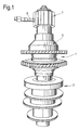
Figure 1 is a perspective illustration showing a compressor rotor mounted to a balance simulator, in combination with a hydraulic system; -
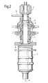
Figure 2 is a schematic cross-sectional view taken through the arrangement ofFigure 1 ; -
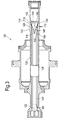
Figure 3 is a schematic cross-sectional view through a tension fuse assembly in accordance with an embodiment of the disclosure, showing the structure in a normal condition; -
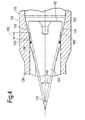
Figure 4 is a schematic cross-sectional view of the first ends of the tubular member and catcher rod of the assembly ofFigure 3 in a normal condition; -
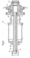
Figure 5 shows a schematic sectional view of a compressor rotor mounted to the tension fuse assembly ofFigure 3 , in combination with a hydraulic system; and -
Figure 6 shows a view of a partially sectioned tension fuse assembly of the disclosure in an actuated condition. - It is noted that the drawings may not be to scale. The drawings are intended to depict only typical aspects of the disclosure, and therefore should not be considered as limiting the scope of the disclosure. In the drawings, like numbering represents like elements between the drawings.
- Turning now to consider the drawings in more detail,
Figures 1 and2 illustrate a gasturbine engine rotor 1 mounted to abalance simulator 2. Therotor 1 may take the form of a compressor rotor, or a turbine rotor. - As illustrated most clearly in
Figure 2 , therotor 1 is mounted co-axially with thebalance simulator 2 for co-rotation with the balance simulator about a longitudinal axis 3. More particularly, therotor 1 is mounted to ashaft 4 which extends (vertically in the orientation illustrated) outwardly from thebalance simulator 2 along the axis 3. Therotor 1 is mounted so as to axially abut thebalance simulator 2, and is clamped tightly between thebalance simulator 2 and acompression unit 5 which is tightly connected to theshaft 4 via anut 6. - In order to ensure that the
rotor 1 is securely clamped between thebalance simulator 2 and thecompression unit 5, a large tensile load is applied to theshaft 4 prior to thecompression unit 5 being connected to theshaft 4 via thenut 6, thereby effectively stretching theshaft 4. This is achieved by using ahydraulic arrangement 7 which is arranged so as to bear against thecompression unit 5 and which is actuatable, via a supply of hydraulic fluid which is flowed into the arrangement via aninlet duct 8, in order to apply the necessary tensile load to theshaft 4. When the appropriate load is applied to theshaft 4 thecompression unit 5 is secured to theshaft 4 by tightening thenut 6, after which thehydraulic arrangement 7 can be removed, leaving therotor 1 tightly clamped between thebalance unit 2 and thecompression unit 5. - However, as indicated above, the tensile load which is required to be applied to the
shaft 4 in this type of assembly is very high, and sometimes defects in theshaft 4 or other components can result in failure of the assembly, particularly during the process of applying the tensile load to theshaft 4 before thecompression unit 5 is secured to theshaft 4. For example, instances have been experienced where such a failure has occurred in theshaft 4 at a position indicated schematically at 9 infigure 2 , where therotor 1 abuts thebalance unit 2. Because the load applied to theshaft 4 is tensile, this type of failure results in all of the hardware above (in the orientation illustrated) the failure site becoming released. This can be very dangerous to people working in the vicinity of the assembly. - Referring to
Figures 3 to 5 , a fuse assembly according to an embodiment of the disclosure is designated generally by thereference numeral 100. - The
fuse assembly 100 comprises an elongatetubular member 110, and acatcher rod 140. - The elongate
tubular member 110 has afirst end portion 114, an oppositesecond end portion 122, and acentre portion 126 positioned between thefirst end portion 114 and thesecond end portion 122. - A
cross-sectional area 128 of thecentre portion 126 is less than across-sectional area 112 of the remainder of thetubular member 110. - The
centre portion 126 of thetubular member 110 is provided with aninspection feature 130. Across-sectional area 132 of theinspection feature 130 is less than across-sectional area 128 of the remainder of thecentre portion 126. - The
catcher rod 140 has afirst end portion 142, and an oppositesecond end portion 160. - The
catcher rod 140 is accommodated concentrically within thetubular member 110. - The
second end portion 160 of thecatcher rod 140 is secured to thesecond end portion 122 of thetubular member 110. - The
first end portion 114 of thetubular member 110 is provided with a first divergentconical portion 116. Thefirst end portion 142 of thecatcher rod 140 is provided with a second divergentconical portion 144. - The
first end portion 114 of thetubular member 110 has a firstcylindrical portion 120 proximal to the first divergentconical portion 116. Thefirst end portion 142 of thecatcher rod 140 has a secondcylindrical portion 148 proximal to the second divergentconical portion 144. - The
first end portion 142 of thecatcher rod 140 is provided with a thirdcylindrical portion 152 distal to the second divergentconical portion 144. - The
catcher rod 140 is positioned concentrically within thetubular member 110 with the second divergentconical portion 144 being axially separated from the first divergentconical portion 116 by apre-determined distance 150. - The second
cylindrical portion 148 is slidably accommodated within the firstcylindrical portion 120. In the arrangement of the present disclosure the secondcylindrical portion 148 is a loose running fit within the firstcylindrical portion 120. In other words the fit between the firstcylindrical portion 120 and the secondcylindrical portion 148 can be categorised as ISO H11/c11 (hole basis) or C11/h11 (shaft basis). - The
catcher rod 140 is positioned concentrically within thetubular member 110 with the second divergentconical portion 144 being axially separated from the first divergentconical portion 116 by apre-determined distance 150. - The second cylindrical portion comprises a
seal element 156 in the form of an 'O'-ring seal. The 'O'-ring seal is positioned along the secondcylindrical portion 148. - In use, in the event of a breakage of the
tubular member 110, the second divergentconical portion 144 engages with the first divergentconical portion 116 to limit the axial movement of thetubular member 110. -
Figure 6 shows a cut-away section of a balance simulator shaft incorporating afuse assembly 100 in which a failure of thetubular member 110 has been initiated. The engagement of the second divergent conical portion with the first divergent conical portion can be clearly seen in this figure. - Except where mutually exclusive, any of the features may be employed separately or in combination with any other features and the disclosure extends to and includes all combinations and sub-combinations of one or more features described herein.
- The foregoing description of various aspects of the disclosure has been presented for purposes of illustration and description. It is not intended to be exhaustive or to limit the disclosure to the precise form disclosed, and obviously, many modifications and variations are possible. Such modifications and variations that may be apparent to a person of skill in the art are included within the scope of the disclosure as defined by the accompanying claims.
in the event of breakage of the tubular member, the second divergent conical portion engages with the first divergent conical portion to limit the axial movement of the tubular member.
Claims (12)
- A tension fuse assembly (100) comprising:an elongate tubular member (110), the tubular member (110) having a first end portion (114) and an opposite second end portion (122); anda catcher rod (140), the catcher rod (140) having a first end portion (142) and an opposite second end portion (160), the catcher rod (140) being accommodated concentrically within the tubular member (110), the second end portion (160) of the catcher rod (140) being secured to the second end portion (122) of the tubular member (110),wherein the first end portion (114) of the tubular member (110) is provided with a first divergent conical portion (116), the first end portion (142) of the catcher rod (140) is provided with a second divergent conical portion (144), and
in the event of breakage of the tubular member (110), the second divergent conical portion (144) engages with the first divergent conical portion (116) to limit the axial movement of the tubular member (110). - The tension fuse assembly (100) as claimed in Claim 1, wherein the first divergent conical portion (116) has a first vertex angle, and the second divergent conical portion (144) has a second vertex angle, and the first vertex angle is greater than the second vertex angle.
- The tension fuse assembly (100) as claimed in Claim 1 or Claim 2, wherein the first end portion (114) of the tubular member (110) comprises a first cylindrical portion (120) proximal to the first divergent conical portion (116), and the first end portion (142) of the catcher rod (140) comprises a second cylindrical portion (148) proximal to the second divergent conical portion (144), the second cylindrical portion (148) being slidably accommodated within the first cylindrical portion (120).
- The tension fuse assembly (100) as claimed in Claim 3, wherein the second cylindrical portion (148) is a loose running fit within the first cylindrical portion (120).
- The tension fuse assembly (100) as claimed in any one of Claims 1 to 4, wherein the catcher rod (140) is positioned concentrically within the tubular member (110) with the second divergent conical portion (144) being axially separated from the first divergent conical portion (116) by a pre-determined distance (150).
- The tension fuse assembly (100) as claimed in any one of Claims 1 to 5, wherein the second cylindrical portion (148) comprises a seal element (156), the seal element (156) configured to rub against the first cylindrical portion (120).
- The tension fuse assembly (100) as claimed in Claim 6, wherein the seal element (156) is selected from the group comprising 'O'-rings, lip seals and ring seals.
- The tension fuse assembly (100) as claimed in any one of Claims 1 to 7, wherein the tubular member (110) further comprises a centre portion (126) interposed between the first end portion (114) and the second end portion (122), the first end portion (114) having a first diameter, the second end portion (122) having a second diameter, the centre portion (126) having a third diameter, and the third diameter (xxx) being less than the first and second diameters.
- The tension fuse assembly (100) as claimed in Claim 8, wherein the centre portion (126) comprises an inspection feature (130), a cross-sectional area (132) of the tubular member (110) at the inspection feature (130) being less than the cross-sectional area (112) of the tubular member (110) along the remainder of the centre portion (126).
- The tension fuse assembly (100) as claimed in any one of Claims 1 to 9, wherein the first end portion (142) of the catcher rod (140) further comprises a third cylindrical portion (152) distal to the second divergent conical portion (144).
- A method of applying a tensile load to a component (170), using a tension fuse assembly (100), the tension fuse assembly (100) comprising an elongate tubular member (110) and a catcher rod (140), the tubular member (110) having a first end portion (114) and a second end portion (122), the catcher rod (140) having a first end portion (142) and a second end portion (160), the first end portion (114) of the tubular member (110) being provided with a first divergent conical portion (116), the first end portion (142) of the catcher rod (140) being provided with a second divergent conical portion (144), the method comprising the steps of:positioning the catcher rod (140) concentrically within the tubular member (110);securing the second end portion (160) of the catcher rod (140) to the second end portion (122) of the tubular member (110);positioning the component (170) over the first end portion (114) of the tubular member (110);securing a tensioning mechanism (180) to the first end portion (114) of the tubular member (110);applying a tensile force between the first end portion (114) of the tubular member (110) and the component (170); andin the event of a breakage of the tubular member (110), the second divergent conical portion (144) engages with the first divergent conical portion (116) to limit the axial movement of the tubular member (110), the component (170) and the tensioning mechanism (180).
- The method as claimed in Claim 11, wherein the step of positioning the catcher rod (140) concentrically within the tubular member (110) comprises the step of:positioning the catcher rod (140) concentrically within the tubular member (110) such that the second divergent conical portion (144) is axially separated from the first divergent conical portion (116) by a pre-determined distance (150).
Applications Claiming Priority (1)
| Application Number | Priority Date | Filing Date | Title |
|---|---|---|---|
| GBGB1519792.4A GB201519792D0 (en) | 2015-11-10 | 2015-11-10 | A system and method for applying a tesile load to a component |
Publications (1)
| Publication Number | Publication Date |
|---|---|
| EP3168588A1 true EP3168588A1 (en) | 2017-05-17 |
Family
ID=55132545
Family Applications (1)
| Application Number | Title | Priority Date | Filing Date |
|---|---|---|---|
| EP16194302.2A Withdrawn EP3168588A1 (en) | 2015-11-10 | 2016-10-18 | A system and method for applying a tensile load to a component |
Country Status (3)
| Country | Link |
|---|---|
| US (1) | US20170130609A1 (en) |
| EP (1) | EP3168588A1 (en) |
| GB (1) | GB201519792D0 (en) |
Cited By (4)
| Publication number | Priority date | Publication date | Assignee | Title |
|---|---|---|---|---|
| EP3647537A1 (en) * | 2018-10-30 | 2020-05-06 | Siemens Aktiengesellschaft | Safety apparatus and corresponding method for containing an energy release from a tension stud of a rotor assembly |
| EP3647538A1 (en) * | 2018-10-30 | 2020-05-06 | Siemens Aktiengesellschaft | Safety apparatus for containing an energy release from a rotor assembly |
| CN112996985A (en) * | 2018-10-30 | 2021-06-18 | 西门子能源环球有限责任两合公司 | Safety device |
| CN113167118A (en) * | 2018-10-30 | 2021-07-23 | 西门子能源环球有限责任两合公司 | Safety device |
Families Citing this family (1)
| Publication number | Priority date | Publication date | Assignee | Title |
|---|---|---|---|---|
| US20180216466A1 (en) * | 2016-10-14 | 2018-08-02 | Pw Power Systems, Inc. | Methods and systems for rotating component balancing |
Citations (3)
| Publication number | Priority date | Publication date | Assignee | Title |
|---|---|---|---|---|
| GB898164A (en) * | 1960-01-26 | 1962-06-06 | Austin Motor Co Ltd | Improved means for clamping rotor assemblies |
| GB2220728A (en) * | 1988-07-15 | 1990-01-17 | Nuovo Pignone Spa | System for disengageably coupling a rotor body to rotary machines,in particular gas turbines and rotary dobbies. |
| DE29702954U1 (en) * | 1996-06-29 | 1997-10-30 | Sartorius AG, 37075 Göttingen | Overload protection for the weighing pan of an upper pan weighing machine |
-
2015
- 2015-11-10 GB GBGB1519792.4A patent/GB201519792D0/en not_active Ceased
-
2016
- 2016-10-18 US US15/296,904 patent/US20170130609A1/en not_active Abandoned
- 2016-10-18 EP EP16194302.2A patent/EP3168588A1/en not_active Withdrawn
Patent Citations (3)
| Publication number | Priority date | Publication date | Assignee | Title |
|---|---|---|---|---|
| GB898164A (en) * | 1960-01-26 | 1962-06-06 | Austin Motor Co Ltd | Improved means for clamping rotor assemblies |
| GB2220728A (en) * | 1988-07-15 | 1990-01-17 | Nuovo Pignone Spa | System for disengageably coupling a rotor body to rotary machines,in particular gas turbines and rotary dobbies. |
| DE29702954U1 (en) * | 1996-06-29 | 1997-10-30 | Sartorius AG, 37075 Göttingen | Overload protection for the weighing pan of an upper pan weighing machine |
Cited By (12)
| Publication number | Priority date | Publication date | Assignee | Title |
|---|---|---|---|---|
| EP3647537A1 (en) * | 2018-10-30 | 2020-05-06 | Siemens Aktiengesellschaft | Safety apparatus and corresponding method for containing an energy release from a tension stud of a rotor assembly |
| EP3647538A1 (en) * | 2018-10-30 | 2020-05-06 | Siemens Aktiengesellschaft | Safety apparatus for containing an energy release from a rotor assembly |
| WO2020088809A1 (en) | 2018-10-30 | 2020-05-07 | Siemens Aktiengesellschaft | Safety apparatus for containing an energy release from a rotor assembly |
| WO2020088811A1 (en) * | 2018-10-30 | 2020-05-07 | Siemens Aktiengesellschaft | Safety apparatus and corresponding method for containing an energy release from a tension stud of a rotor assembly |
| CN112955630A (en) * | 2018-10-30 | 2021-06-11 | 西门子能源环球有限责任两合公司 | Safety device for accommodating energy release from a tension stud of a rotor assembly and corresponding method |
| CN112955629A (en) * | 2018-10-30 | 2021-06-11 | 西门子能源环球有限责任两合公司 | Safety device for accommodating energy release from a rotor assembly |
| CN112996985A (en) * | 2018-10-30 | 2021-06-18 | 西门子能源环球有限责任两合公司 | Safety device |
| CN113167118A (en) * | 2018-10-30 | 2021-07-23 | 西门子能源环球有限责任两合公司 | Safety device |
| US11519301B2 (en) | 2018-10-30 | 2022-12-06 | Siemens Energy Global GmbH & Co. KG | Safety apparatus and corresponding method for containing an energy release from a tension stud of a rotor assembly |
| CN112955629B (en) * | 2018-10-30 | 2023-03-10 | 西门子能源环球有限责任两合公司 | Safety device to accommodate the release of energy from the rotor assembly |
| US11795835B2 (en) | 2018-10-30 | 2023-10-24 | Siemens Energy Global GmbH & Co. KG | Safety apparatus for containing an energy release from a rotor assembly |
| US11891914B2 (en) | 2018-10-30 | 2024-02-06 | Siemens Energy Global GmbH & Co. KG | Safety apparatus |
Also Published As
| Publication number | Publication date |
|---|---|
| US20170130609A1 (en) | 2017-05-11 |
| GB201519792D0 (en) | 2015-12-23 |
Similar Documents
| Publication | Publication Date | Title |
|---|---|---|
| EP3168588A1 (en) | A system and method for applying a tensile load to a component | |
| US9810096B2 (en) | Turbomachine fan casing assembly | |
| US10823179B2 (en) | Method of assembling a set of impellers through tie rods impeller and turbomachine | |
| RU2015154969A (en) | DEVICE FOR BONDING TWO PARTS BETWEEN YOURSELF | |
| US9695854B2 (en) | Adjustable and lockable turnbuckle | |
| EP3312390B1 (en) | Flange fastening assembly in a gas turbine engine | |
| EP2966429B1 (en) | Method for detecting leakage of a dynamic seal in an aircraft landing gear | |
| JP7448533B2 (en) | Methods and tools for repairing damaged threads | |
| JP2017083013A (en) | Sealing nut | |
| KR20110085973A (en) | Internal restraint | |
| KR101717734B1 (en) | Caulking method for preventing piston of hydraulic/pneumatic cylinder from being loosened | |
| JP6900237B2 (en) | Turbomachinery | |
| DE112015000686T5 (en) | shock absorber | |
| US20150050138A1 (en) | Fixation device for turbine and method for applying fixation | |
| CH714205B1 (en) | Turbocharger. | |
| US10138946B2 (en) | System and method for applying a tensile load to a component, having a mechanical fuse | |
| KR20140099378A (en) | Apparatus for maintaining gap between pipes | |
| US20160176031A1 (en) | Threaded pin remover | |
| EP2278176B1 (en) | Method of preloading a coupling assembly | |
| EP3255345A1 (en) | Installation tool and system for assembling a gas turbine combustor | |
| CH706977A2 (en) | Tube holder for use in turbomachinery, with a cylinder disposed in a housing metal foam part. | |
| US20140178185A1 (en) | Egress seal assembly | |
| JP2017032563A (en) | System and method for nut swaging verification | |
| JP2020070901A (en) | Pipe repair method and pipe repair member | |
| GB2522241A (en) | Protection device |
Legal Events
| Date | Code | Title | Description |
|---|---|---|---|
| PUAI | Public reference made under article 153(3) epc to a published international application that has entered the european phase |
Free format text: ORIGINAL CODE: 0009012 |
|
| STAA | Information on the status of an ep patent application or granted ep patent |
Free format text: STATUS: THE APPLICATION HAS BEEN PUBLISHED |
|
| AK | Designated contracting states |
Kind code of ref document: A1 Designated state(s): AL AT BE BG CH CY CZ DE DK EE ES FI FR GB GR HR HU IE IS IT LI LT LU LV MC MK MT NL NO PL PT RO RS SE SI SK SM TR |
|
| AX | Request for extension of the european patent |
Extension state: BA ME |
|
| STAA | Information on the status of an ep patent application or granted ep patent |
Free format text: STATUS: THE APPLICATION IS DEEMED TO BE WITHDRAWN |
|
| 18D | Application deemed to be withdrawn |
Effective date: 20171118 |