EP3168578A1 - Estimating system parameters from sensor measurements - Google Patents
Estimating system parameters from sensor measurements Download PDFInfo
- Publication number
- EP3168578A1 EP3168578A1 EP16189340.9A EP16189340A EP3168578A1 EP 3168578 A1 EP3168578 A1 EP 3168578A1 EP 16189340 A EP16189340 A EP 16189340A EP 3168578 A1 EP3168578 A1 EP 3168578A1
- Authority
- EP
- European Patent Office
- Prior art keywords
- parameter signal
- sensor
- estimated
- parameter
- estimated parameter
- Prior art date
- Legal status (The legal status is an assumption and is not a legal conclusion. Google has not performed a legal analysis and makes no representation as to the accuracy of the status listed.)
- Granted
Links
Images




Classifications
-
- G—PHYSICS
- G01—MEASURING; TESTING
- G01D—MEASURING NOT SPECIALLY ADAPTED FOR A SPECIFIC VARIABLE; ARRANGEMENTS FOR MEASURING TWO OR MORE VARIABLES NOT COVERED IN A SINGLE OTHER SUBCLASS; TARIFF METERING APPARATUS; MEASURING OR TESTING NOT OTHERWISE PROVIDED FOR
- G01D18/00—Testing or calibrating apparatus or arrangements provided for in groups G01D1/00 - G01D15/00
-
- G—PHYSICS
- G01—MEASURING; TESTING
- G01D—MEASURING NOT SPECIALLY ADAPTED FOR A SPECIFIC VARIABLE; ARRANGEMENTS FOR MEASURING TWO OR MORE VARIABLES NOT COVERED IN A SINGLE OTHER SUBCLASS; TARIFF METERING APPARATUS; MEASURING OR TESTING NOT OTHERWISE PROVIDED FOR
- G01D5/00—Mechanical means for transferring the output of a sensing member; Means for converting the output of a sensing member to another variable where the form or nature of the sensing member does not constrain the means for converting; Transducers not specially adapted for a specific variable
- G01D5/12—Mechanical means for transferring the output of a sensing member; Means for converting the output of a sensing member to another variable where the form or nature of the sensing member does not constrain the means for converting; Transducers not specially adapted for a specific variable using electric or magnetic means
- G01D5/244—Mechanical means for transferring the output of a sensing member; Means for converting the output of a sensing member to another variable where the form or nature of the sensing member does not constrain the means for converting; Transducers not specially adapted for a specific variable using electric or magnetic means influencing characteristics of pulses or pulse trains; generating pulses or pulse trains
- G01D5/24471—Error correction
-
- G—PHYSICS
- G01—MEASURING; TESTING
- G01D—MEASURING NOT SPECIALLY ADAPTED FOR A SPECIFIC VARIABLE; ARRANGEMENTS FOR MEASURING TWO OR MORE VARIABLES NOT COVERED IN A SINGLE OTHER SUBCLASS; TARIFF METERING APPARATUS; MEASURING OR TESTING NOT OTHERWISE PROVIDED FOR
- G01D18/00—Testing or calibrating apparatus or arrangements provided for in groups G01D1/00 - G01D15/00
- G01D18/001—Calibrating encoders
-
- G—PHYSICS
- G01—MEASURING; TESTING
- G01D—MEASURING NOT SPECIALLY ADAPTED FOR A SPECIFIC VARIABLE; ARRANGEMENTS FOR MEASURING TWO OR MORE VARIABLES NOT COVERED IN A SINGLE OTHER SUBCLASS; TARIFF METERING APPARATUS; MEASURING OR TESTING NOT OTHERWISE PROVIDED FOR
- G01D5/00—Mechanical means for transferring the output of a sensing member; Means for converting the output of a sensing member to another variable where the form or nature of the sensing member does not constrain the means for converting; Transducers not specially adapted for a specific variable
- G01D5/12—Mechanical means for transferring the output of a sensing member; Means for converting the output of a sensing member to another variable where the form or nature of the sensing member does not constrain the means for converting; Transducers not specially adapted for a specific variable using electric or magnetic means
- G01D5/244—Mechanical means for transferring the output of a sensing member; Means for converting the output of a sensing member to another variable where the form or nature of the sensing member does not constrain the means for converting; Transducers not specially adapted for a specific variable using electric or magnetic means influencing characteristics of pulses or pulse trains; generating pulses or pulse trains
- G01D5/24471—Error correction
- G01D5/24476—Signal processing
-
- G—PHYSICS
- G01—MEASURING; TESTING
- G01D—MEASURING NOT SPECIALLY ADAPTED FOR A SPECIFIC VARIABLE; ARRANGEMENTS FOR MEASURING TWO OR MORE VARIABLES NOT COVERED IN A SINGLE OTHER SUBCLASS; TARIFF METERING APPARATUS; MEASURING OR TESTING NOT OTHERWISE PROVIDED FOR
- G01D5/00—Mechanical means for transferring the output of a sensing member; Means for converting the output of a sensing member to another variable where the form or nature of the sensing member does not constrain the means for converting; Transducers not specially adapted for a specific variable
- G01D5/12—Mechanical means for transferring the output of a sensing member; Means for converting the output of a sensing member to another variable where the form or nature of the sensing member does not constrain the means for converting; Transducers not specially adapted for a specific variable using electric or magnetic means
- G01D5/244—Mechanical means for transferring the output of a sensing member; Means for converting the output of a sensing member to another variable where the form or nature of the sensing member does not constrain the means for converting; Transducers not specially adapted for a specific variable using electric or magnetic means influencing characteristics of pulses or pulse trains; generating pulses or pulse trains
- G01D5/24471—Error correction
- G01D5/2449—Error correction using hard-stored calibration data
-
- G—PHYSICS
- G05—CONTROLLING; REGULATING
- G05B—CONTROL OR REGULATING SYSTEMS IN GENERAL; FUNCTIONAL ELEMENTS OF SUCH SYSTEMS; MONITORING OR TESTING ARRANGEMENTS FOR SUCH SYSTEMS OR ELEMENTS
- G05B13/00—Adaptive control systems, i.e. systems automatically adjusting themselves to have a performance which is optimum according to some preassigned criterion
- G05B13/02—Adaptive control systems, i.e. systems automatically adjusting themselves to have a performance which is optimum according to some preassigned criterion electric
- G05B13/04—Adaptive control systems, i.e. systems automatically adjusting themselves to have a performance which is optimum according to some preassigned criterion electric involving the use of models or simulators
Definitions
- the present invention relates generally to methods and systems for measuring parameters using sensors, and more particularly to estimating system parameters when sensor measurements exhibit time delays due to slow response times of the sensor.
- temperature sensors are located at the exhaust duct. At this location, shielding is required that will slow down the time response of the temperature sensor.
- Electronic engine control systems sometimes compensate the slow dynamics of the temperature sensor by introducing lead or derivative type compensation in inter turbine temperature limiting loops.
- this type of controller has to be designed on a case-by-case basis and its tuning is very time-consuming.
- Other compensation methods are also known, but they are susceptible to noise, require additional components, and in some cases involve linking the measured parameter to a specific engine dynamic, which is not always feasible.
- a method for estimating a system parameter measured by a sensor comprising receiving a measured parameter signal from the sensor, the measured parameter signal corresponding to a current measurement of the system parameter; and in a closed-loop scheme, generating an estimated parameter signal based on the measured parameter signal and on past measurements of the system parameter; outputting the estimated parameter signal as an estimate of the system parameter; and iteratively correcting the estimated parameter signal using pre-characterized sensor dynamics for the sensor from which the system parameter is received until a steady state is reached, each corrected iteration of the estimated parameter signal being output as the estimated parameter signal.
- iteratively correcting the estimated parameter signal comprises calculating a model-based parameter signal from the estimated parameter signal using the sensor dynamics; determining an estimation error by subtracting the model-based parameter signal from the measured parameter signal; and applying the estimation error to the estimated parameter signal to obtain the estimated parameter signal as corrected.
- steady state is reached when the estimation error is substantially zero.
- calculating a model-based parameter signal using the sensor dynamics comprises using bounded characteristics of the sensor, and wherein generating an estimated parameter signal and correcting the estimated parameter signal comprises maintaining the estimated parameter signal within the bounded characteristics of the sensor.
- the senor is a temperature sensor, and wherein the parameter is a temperature at a given location in a gas turbine engine.
- calculating the model-based parameter signal using the sensor dynamics comprises modeling the sensor using a first order system.
- the temperature sensor has a nonlinear characteristic modeled by piece-wise linearization throughout an operating envelop of the gas turbine engine.
- the given location is one of an inlet duct and an exhaust duct.
- a device for estimating a system parameter measured by a sensor comprises a memory having stored thereon program code executable by a processor and/or at least one processor configured for executing the program code.
- the program code and/or the circuit is configured for receiving a measured parameter signal from the sensor, the measured parameter signal corresponding to a current measurement of the system parameter, and in a closed loop scheme, generating an estimated parameter signal based on the measured parameter signal and on past measurements of the system parameter; outputting the estimated parameter signal as an estimate of the system parameter; and iteratively correcting the estimated parameter signal using pre-characterized sensor dynamics for the sensor from which the system parameter is received until a steady state is reached, each corrected iteration of the estimated parameter signal being output as the estimated parameter signal.
- iteratively correcting the estimated parameter signal comprises calculating a model-based parameter signal from the estimated parameter signal using the sensor dynamics; determining an estimation error by subtracting the model-based parameter signal from the measured parameter signal; and applying the estimation error to the estimated parameter signal to obtain the estimated parameter signal as corrected.
- steady state is reached when the estimation error is substantially zero.
- calculating a model-based parameter signal using the sensor dynamics comprises using bounded characteristics of the sensor, and wherein generating an estimated parameter signal and correcting the estimated parameter signal comprises maintaining the estimated parameter signal within the bounded characteristics of the sensor.
- the senor is a temperature sensor
- the parameter is a temperature at a given location in a gas turbine engine
- calculating the model-based parameter signal using the sensor dynamics comprises modeling the sensor using a first order system.
- the temperature sensor has a nonlinear characteristic modeled by piece-wise linearization throughout an operating envelop of the gas turbine engine.
- the given location is one of an inlet duct and an exhaust duct.
- a device for estimating a system parameter measured by a sensor comprising means for receiving a measured parameter signal from the sensor; means for generating an estimated parameter signal based on the measured parameter signal and on past measurements of the system parameter; means for calculating a model-based parameter signal from the estimated parameter signal using pre-characterized sensor dynamics for the sensor from which the system parameter is received; means for determining an estimation error by subtracting the model-based parameter signal from the measured parameter signal; means for correcting the estimated parameter signal using the estimation error to generate a corrected estimated parameter signal; and means for outputting the corrected estimated parameter signal as an estimate of the system parameter.
- closed loop scheme should be understood to refer to a control system which uses a feedback control action in order to reduce errors within the system. A part of the output signal is fed back to the input for comparison with a desired set point condition, and the error is converted into a control action designed to bring the system to a desired response.
- System parameters are estimated in order to account for a sensor's inability to measure a rapid change in the parameter.
- the system parameter may be any physically measurable parameter, such as but not limited to, temperature, pressure, speed, position, load, flow rate, voltage, distance, and acceleration.
- the sensor may be any type of sensor that is capable of measuring a system parameter, such as but not limited to, thermal, heat and temperature sensors; pressure sensors; force, density and level sensors; and flow and fluid velocity sensors.
- Known or pre-determined sensor dynamics are used to estimate the sensor measurement.
- the methods and systems are applicable to a variety of applications. Examples of applications include engine control systems, such as those for gas turbine engines and more specifically, for turbo shaft engines, turbo propeller engines, and turbo fan engines.
- the sensor may be used to measure inlet and/or exhaust temperature of a gas turbine engine.
- Other examples of applications include HVAC (Heating, Ventilation, Air Conditioning) control systems, fuel cells, pumps, drills, vehicles, or any other type of machine through which gases or liquids circulate and from which measurements may be obtained.
- HVAC Heating, Ventilation, Air Conditioning
- a measured parameter signal is received from a sensor.
- the MPS corresponds to a current measurement of the system parameter.
- the system parameter is the exhaust gas temperature captured by what is commonly referred to as a T6 thermocouple
- the received MPS is the temperature as currently measured by the T6 thermocouple.
- an estimated parameter signal is generated based on the MPS and on past measurements of the system parameter.
- the EPS is iteratively refined (or corrected) using pre-characterized sensor dynamics for the sensor from which the system parameter was measured, until a steady-state is reached.
- the corrected EPS is output as the estimate of the system parameter.
- Figure 2 is a flowchart of an exemplary embodiment for the iterative correction of the EPS, as per 106 of figure 1 .
- the iterative correction is performed by calculating a model-based parameter signal from the EPS using the dynamic characteristics of the sensor, as per 202.
- an estimation error is determined by comparing the model-based parameter signal with the MPS.
- the estimation error is applied to the EPS to obtain a corrected EPS.
- FIG. 3 is a block diagram of an embodiment for estimating the system parameter.
- the MPS is received at input 301 and provided to the system 300, which is referred to herein as an estimator.
- the estimator 300 provides a corrected EPS at output 307.
- An observer unit 302 receives the MPS at the first iteration of the process, generates the EPS based on the MPS and on past measurements of the system parameter, and provides the EPS to a sensor dynamics unit 304.
- the sensor dynamics unit 304 calculates the model-based parameter signal which is output and returned to the observer unit 304 via a negative feedback loop.
- a comparator 306 is used to determine the estimation error, by subtracting the model-based parameter signal from the MPS. The estimation error is then applied to the EPS by the observer unit 302 in order to obtain the corrected EPS. Note that the estimation error may be determined using other known means once the model-based parameter signal has been calculated, and may be performed by the observer unit 302 or by the sensor dynamics unit 304.
- the estimator 300 is thus represented by a closed-loop system, with the observer unit 302 corresponding to the open-loop gains of the system and is the forward path, and the sensor dynamics unit 304 representing the gain of the sensor in the feedback path.
- the comparator 306 is the summing point between the feedback loop and the system's input.
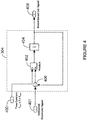
- Figure 4 is an exemplary embodiment of the sensor dynamics unit 304, for a thermocouple sensor.
- the sensor dynamics may be represented by a first order system H(s) having a time constant ⁇ that may be any value between ⁇ min and ⁇ max .
- the behavior of the estimated value can be tailored to the required characteristic by fine-tuning of the time constant. For example, setting the time constant to ⁇ max may be recommended when it is desired to characterize the maximum possible peak value of the actual temperature. Since the gain of the observer unit 302 may be designed subject to stability and performance, there is no need to redesign the observer unit 302 when the time constant is changed from ⁇ min to ⁇ max .
- a linear model of the sensor is utilized to calculate the model-based parameter throughout the operating envelop of the engine.
- the time constant is received at input 400.
- the EPS is received at input 401 and in a first iteration, a multiplier 402 outputs a product of (estimated parameter) * (time constant).
- An integrator 404 integrates the product to obtain output 408.
- a negative feedback loop subtracts the integrated product from the original estimated parameter via a comparator 406 and sends the result through the multiplier 402 and integrator 404 again.
- the model-based parameter signal is provided at output 408.
- the sensor dynamics unit 304 may also be implemented differently, for example by replacing the sensor model H(s) illustrated above with a more complex model, such as a higher order model or a nonlinear model.
- the sensor is a temperature sensor that has a nonlinear characteristic that is modeled by piece-wise linearization throughout an operating envelop of the gas turbine engine. The higher the fidelity of the sensor model, the greater the accuracy of the estimation provided at the output 307 of the estimator 300.
- the sensor dynamics unit 304 uses bounded characteristics of the sensor. The observer unit 302 may then be designed to stay within these boundaries.
- FIG. 5 is an exemplary embodiment of the observer unit 302.
- the observer unit 302 modulates its estimation as a function of the estimation error. As the estimation error decreases, the estimation is refined.
- the estimation error is received at input 501 and amplified by amplifier 502, which has a gain of K o .
- the output of amplifier 502 is transmitted to another amplifier 504 having a gain inversely proportional to a correcting factor T i .
- the output of amplifier 504 is integrated by integrator 506 and added to the output of amplifier 502 via summer 508, thus providing the EPS.
- the convergence speed of the observer unit 302 may be adjusted via the gain K o of amplifier 502, i.e. the calculated model-based parameter signal converges faster to the measured parameter signal by increasing the gain K o .
- the correcting factor T i may be used to force the estimation error to zero in steady state.
- tuning T i may also be used to control how fast the estimation error goes to zero.
- the sensor dynamic may be subject to change at different operating conditions.
- the time constant of a thermocouple varies with air mass flow around the sensor. Therefore, the sensor time constant will vary from ⁇ min to ⁇ max at different operating conditions.
- the gains of the observer unit 302 K o , T i ) may be designed in a way that provides stability to the closed-loop estimator with regards to changes in the time constant of the sensor dynamics unit 304.
- the time constant of the sensor dynamics unit 304 can be changed in order to tailor the behavior of the estimated signal to the required design characteristic.
- the estimator 300 may preserve its high performance while subject to changes to the time constant.
- estimator gains K o , T i .
- Equation (1a) provides a high performance for the estimator 300 with gains ( K o , T i ) while it is constrained with minimum and maximum bounds on the time constant (equation 1b).
- Equation (1c) provides the stability of the closed loop estimator. It should be noted that the performance equation is not limited to (1a) as It can be tailored based on design objectives.
- a Proportional-Integral (PI) controller is used to implement the observer unit 302, but alternative embodiments, such as higher order compensators, may also be used.
- Figure 6 is a graphical representation of an estimated parameter 606, measured parameter 608, and calculated model-based parameter 610, as a function of time, in accordance with the embodiments of the estimator 300 illustrated in figures 4 and 5 .
- estimated parameter 606 corresponds to a designed time constant, as per the above.
- the estimated parameter 602 with the time constant set as ⁇ max as well as the estimated parameter 604 with the time constant set as ⁇ min .
- the parameter in the example of figure 6 is temperature, it may also be another parameter, such as pressure.
- a temperature overshoot that occurs at about the twelve second mark is captured by the estimated parameter 606 but not by the measured parameter 608, where the fast rise in temperature is masked by the slow response time of the sensor.
- the difference between the measured parameter 608 and the calculated model-based parameter 610 corresponds to the estimation error, which is applied to refine the estimated parameter 606.
- the estimation error is reduced until the estimated parameter 606, the measured parameter 608, and the calculated model-based parameter 610 eventually converge, around the fifteen second mark.
- the technique described herein is not susceptible to noise, contrary to other correction techniques such as using inverse sensor dynamics to eliminate sensor lag.
- the optimal design allows the estimator 300 to keep the noise at an appropriate level. Indeed, the noise level can be lowered by lowering the convergence speed of the calculated model-based parameter signal to the measured parameter signal.
- the estimator 300 may be implemented in hardware, using analog and/or digital circuit components, as illustrated in figures 4 and 5 .
- the estimator 300 may be provided as an application-specific integrated circuit (ASIC) or a field programmable gate array (FPGA).
- the estimator 300 may be implemented in software, as one or more applications running on a computing device 700, as illustrated in figure 7 .
- the computing device 700 illustratively comprises one or more server(s) 701.
- the server 701 may comprise, amongst other things, a plurality of applications 706 1 ... 706 n running on a processor 704 coupled to a memory 702.
- a first application may be used to implement the observer unit 302 while a second application may be used to implement the sensor dynamics unit 304.
- a single application may be used to implement both units 302, 304, or multiple applications may be used to implement each unit 302, 304.
- the memory 702 accessible by the processor 704 may receive and store data.
- the memory 702 may be a main memory, such as a high speed Random Access Memory (RAM), or an auxiliary storage unit, such as a hard disk, a floppy disk, or a magnetic tape drive.
- the memory 702 may be any other type of memory, such as a Read-Only Memory (ROM), or optical storage media such as a videodisc and a compact disc.
- the processor 704 may access the memory 702 to retrieve data.
- the processor 704 may be any device that can perform operations on data. Examples are a central processing unit (CPU), a front-end processor, a microprocessor, and a network processor.
- the applications 706 1 ... 706 n are coupled to the processor 704 and configured to perform the tasks as described above and illustrated in figures 1 and 2 .
- the estimator 300 is implemented using a combination of hardware and software components. In some embodiments, the estimator 300 is provided as a non-transitory computer readable medium having stored thereon program code executable by a processor for carrying out the methods described herein.
Landscapes
- Physics & Mathematics (AREA)
- General Physics & Mathematics (AREA)
- Engineering & Computer Science (AREA)
- Signal Processing (AREA)
- Health & Medical Sciences (AREA)
- Artificial Intelligence (AREA)
- Computer Vision & Pattern Recognition (AREA)
- Evolutionary Computation (AREA)
- Medical Informatics (AREA)
- Software Systems (AREA)
- Automation & Control Theory (AREA)
- Feedback Control In General (AREA)
Abstract
Description
- The present invention relates generally to methods and systems for measuring parameters using sensors, and more particularly to estimating system parameters when sensor measurements exhibit time delays due to slow response times of the sensor.
- Many sensors cannot measure rapid changes in a given parameter, such as temperature or pressure, as they exhibit time delays. This is problematic in engine control systems when data from the sensor is used to make engine decisions. For example, in a gas turbine engine, temperature sensors are located at the exhaust duct. At this location, shielding is required that will slow down the time response of the temperature sensor.
- Electronic engine control systems sometimes compensate the slow dynamics of the temperature sensor by introducing lead or derivative type compensation in inter turbine temperature limiting loops. However, this type of controller has to be designed on a case-by-case basis and its tuning is very time-consuming. Other compensation methods are also known, but they are susceptible to noise, require additional components, and in some cases involve linking the measured parameter to a specific engine dynamic, which is not always feasible.
- There is therefore a need to improve on techniques used to correct measurement signals from sensors.
- There are described herein methods and systems for estimating a system parameter in a closed loop scheme using a sensor model associated with a sensor performing a measurement of the system parameter. Past and current measurements of the parameter are used to provide an initial estimate of the system parameter and sensor dynamics are used to refine the estimated parameter.
- In accordance with a first broad aspect, there is provided a method for estimating a system parameter measured by a sensor, the method comprising receiving a measured parameter signal from the sensor, the measured parameter signal corresponding to a current measurement of the system parameter; and in a closed-loop scheme, generating an estimated parameter signal based on the measured parameter signal and on past measurements of the system parameter; outputting the estimated parameter signal as an estimate of the system parameter; and iteratively correcting the estimated parameter signal using pre-characterized sensor dynamics for the sensor from which the system parameter is received until a steady state is reached, each corrected iteration of the estimated parameter signal being output as the estimated parameter signal.
- In some embodiments of the method, iteratively correcting the estimated parameter signal comprises calculating a model-based parameter signal from the estimated parameter signal using the sensor dynamics; determining an estimation error by subtracting the model-based parameter signal from the measured parameter signal; and applying the estimation error to the estimated parameter signal to obtain the estimated parameter signal as corrected.
- In some embodiments of the method, steady state is reached when the estimation error is substantially zero.
- In some embodiments of the method, calculating a model-based parameter signal using the sensor dynamics comprises using bounded characteristics of the sensor, and wherein generating an estimated parameter signal and correcting the estimated parameter signal comprises maintaining the estimated parameter signal within the bounded characteristics of the sensor.
- In some embodiments of the method, the sensor is a temperature sensor, and wherein the parameter is a temperature at a given location in a gas turbine engine.
- In some embodiments of the method, calculating the model-based parameter signal using the sensor dynamics comprises modeling the sensor using a first order system.
- In some embodiments of the method, the first order system is provided in accordance with:

- In some embodiments of the method, the temperature sensor has a nonlinear characteristic modeled by piece-wise linearization throughout an operating envelop of the gas turbine engine.
- In some embodiments of the method, wherein the given location is one of an inlet duct and an exhaust duct.
- In accordance with another broad aspect, there is provided a device for estimating a system parameter measured by a sensor. The device comprises a memory having stored thereon program code executable by a processor and/or at least one processor configured for executing the program code. The program code and/or the circuit is configured for receiving a measured parameter signal from the sensor, the measured parameter signal corresponding to a current measurement of the system parameter, and in a closed loop scheme, generating an estimated parameter signal based on the measured parameter signal and on past measurements of the system parameter; outputting the estimated parameter signal as an estimate of the system parameter; and iteratively correcting the estimated parameter signal using pre-characterized sensor dynamics for the sensor from which the system parameter is received until a steady state is reached, each corrected iteration of the estimated parameter signal being output as the estimated parameter signal.
- In some embodiments of the device, iteratively correcting the estimated parameter signal comprises calculating a model-based parameter signal from the estimated parameter signal using the sensor dynamics; determining an estimation error by subtracting the model-based parameter signal from the measured parameter signal; and applying the estimation error to the estimated parameter signal to obtain the estimated parameter signal as corrected.
- In some embodiments of the device, steady state is reached when the estimation error is substantially zero.
- In some embodiments of the device, calculating a model-based parameter signal using the sensor dynamics comprises using bounded characteristics of the sensor, and wherein generating an estimated parameter signal and correcting the estimated parameter signal comprises maintaining the estimated parameter signal within the bounded characteristics of the sensor.
- In some embodiments of the device, wherein the sensor is a temperature sensor, and wherein the parameter is a temperature at a given location in a gas turbine engine.
- In some embodiments of the device, calculating the model-based parameter signal using the sensor dynamics comprises modeling the sensor using a first order system.
- In some embodiments of the device, the first order system is provided in accordance with:

- In some embodiments of the device, the temperature sensor has a nonlinear characteristic modeled by piece-wise linearization throughout an operating envelop of the gas turbine engine.
- In some embodiments of the device, the given location is one of an inlet duct and an exhaust duct.
- In accordance with yet another broad aspect, which the Applicant expressly reserves the right to claim independently, there is provided a device for estimating a system parameter measured by a sensor, the device comprising means for receiving a measured parameter signal from the sensor; means for generating an estimated parameter signal based on the measured parameter signal and on past measurements of the system parameter; means for calculating a model-based parameter signal from the estimated parameter signal using pre-characterized sensor dynamics for the sensor from which the system parameter is received; means for determining an estimation error by subtracting the model-based parameter signal from the measured parameter signal; means for correcting the estimated parameter signal using the estimation error to generate a corrected estimated parameter signal; and means for outputting the corrected estimated parameter signal as an estimate of the system parameter.
- In present description, the expression "closed loop scheme" should be understood to refer to a control system which uses a feedback control action in order to reduce errors within the system. A part of the output signal is fed back to the input for comparison with a desired set point condition, and the error is converted into a control action designed to bring the system to a desired response.
- Further features and advantages of the present invention will become apparent from the following detailed description, taken in combination with the appended drawings, in which:
-
Fig. 1 is a flowchart of an embodiment of a method for estimating a system parameter measured by a sensor; -
Fig. 2 is a flowchart of an embodiment for iteratively refining the estimated parameter signal using sensor dynamics; -
Fig. 3 is a block diagram of an embodiment for an estimator; -
Fig. 4 is a block diagram of an embodiment for a sensor dynamics unit; -
Fig. 5 is a block diagram of an embodiment for an observer unit; -
Fig. 6 is a graphical illustration of a measured, estimated, and calculated parameter versus time; and -
Fig. 7 is block diagram of an embodiment for implementing the estimator offigure 3 in a computing device. - It will be noted that throughout the appended drawings, like features are identified by like reference numerals.
- There is described herein methods and systems for estimating system parameters from actual sensor measurements. System parameters are estimated in order to account for a sensor's inability to measure a rapid change in the parameter. The system parameter may be any physically measurable parameter, such as but not limited to, temperature, pressure, speed, position, load, flow rate, voltage, distance, and acceleration. The sensor may be any type of sensor that is capable of measuring a system parameter, such as but not limited to, thermal, heat and temperature sensors; pressure sensors; force, density and level sensors; and flow and fluid velocity sensors.
- Known or pre-determined sensor dynamics are used to estimate the sensor measurement. The methods and systems are applicable to a variety of applications. Examples of applications include engine control systems, such as those for gas turbine engines and more specifically, for turbo shaft engines, turbo propeller engines, and turbo fan engines. For example, the sensor may be used to measure inlet and/or exhaust temperature of a gas turbine engine. Other examples of applications include HVAC (Heating, Ventilation, Air Conditioning) control systems, fuel cells, pumps, drills, vehicles, or any other type of machine through which gases or liquids circulate and from which measurements may be obtained.
- Referring to
figure 1 , there is illustrated a flowchart of an exemplary method for estimating a system parameter. At 102, a measured parameter signal (MPS) is received from a sensor. The MPS corresponds to a current measurement of the system parameter. For example, if the system parameter is the exhaust gas temperature captured by what is commonly referred to as a T6 thermocouple, the received MPS is the temperature as currently measured by the T6 thermocouple. At 104, an estimated parameter signal (EPS) is generated based on the MPS and on past measurements of the system parameter. At 106, 108, 110 the EPS is iteratively refined (or corrected) using pre-characterized sensor dynamics for the sensor from which the system parameter was measured, until a steady-state is reached. At 108, the corrected EPS is output as the estimate of the system parameter. -
Figure 2 is a flowchart of an exemplary embodiment for the iterative correction of the EPS, as per 106 offigure 1 . In this example, the iterative correction is performed by calculating a model-based parameter signal from the EPS using the dynamic characteristics of the sensor, as per 202. At 204, an estimation error is determined by comparing the model-based parameter signal with the MPS. At 206, the estimation error is applied to the EPS to obtain a corrected EPS. - The method of
figures 1 and2 will be explained in more detail with regards tofigure 3 , which is a block diagram of an embodiment for estimating the system parameter. The MPS is received atinput 301 and provided to thesystem 300, which is referred to herein as an estimator. Theestimator 300 provides a corrected EPS atoutput 307. Anobserver unit 302 receives the MPS at the first iteration of the process, generates the EPS based on the MPS and on past measurements of the system parameter, and provides the EPS to asensor dynamics unit 304. Thesensor dynamics unit 304 calculates the model-based parameter signal which is output and returned to theobserver unit 304 via a negative feedback loop. In the embodiment illustrated, acomparator 306 is used to determine the estimation error, by subtracting the model-based parameter signal from the MPS. The estimation error is then applied to the EPS by theobserver unit 302 in order to obtain the corrected EPS. Note that the estimation error may be determined using other known means once the model-based parameter signal has been calculated, and may be performed by theobserver unit 302 or by thesensor dynamics unit 304. - The
estimator 300 is thus represented by a closed-loop system, with theobserver unit 302 corresponding to the open-loop gains of the system and is the forward path, and thesensor dynamics unit 304 representing the gain of the sensor in the feedback path. Thecomparator 306 is the summing point between the feedback loop and the system's input. -
Figure 4 is an exemplary embodiment of thesensor dynamics unit 304, for a thermocouple sensor. In this case, the sensor dynamics may be represented by a first order system H(s) having a time constant τ that may be any value between τmin and τmax. The behavior of the estimated value can be tailored to the required characteristic by fine-tuning of the time constant. For example, setting the time constant to τmax may be recommended when it is desired to characterize the maximum possible peak value of the actual temperature. Since the gain of theobserver unit 302 may be designed subject to stability and performance, there is no need to redesign theobserver unit 302 when the time constant is changed from τmin to τmax. An exemplary first order system is thus presented as:
- In the example illustrated in
figure 4 , a linear model of the sensor is utilized to calculate the model-based parameter throughout the operating envelop of the engine. The time constant is received atinput 400. The EPS is received atinput 401 and in a first iteration, amultiplier 402 outputs a product of (estimated parameter) * (time constant). Anintegrator 404 integrates the product to obtainoutput 408. A negative feedback loop subtracts the integrated product from the original estimated parameter via acomparator 406 and sends the result through themultiplier 402 andintegrator 404 again. The model-based parameter signal is provided atoutput 408. - The
sensor dynamics unit 304 may also be implemented differently, for example by replacing the sensor model H(s) illustrated above with a more complex model, such as a higher order model or a nonlinear model. In some embodiments, the sensor is a temperature sensor that has a nonlinear characteristic that is modeled by piece-wise linearization throughout an operating envelop of the gas turbine engine. The higher the fidelity of the sensor model, the greater the accuracy of the estimation provided at theoutput 307 of theestimator 300. In some embodiments, thesensor dynamics unit 304 uses bounded characteristics of the sensor. Theobserver unit 302 may then be designed to stay within these boundaries. -
Figure 5 is an exemplary embodiment of theobserver unit 302. Theobserver unit 302 modulates its estimation as a function of the estimation error. As the estimation error decreases, the estimation is refined. The estimation error is received atinput 501 and amplified byamplifier 502, which has a gain of Ko. The output ofamplifier 502 is transmitted to anotheramplifier 504 having a gain inversely proportional to a correcting factor Ti. The output ofamplifier 504 is integrated byintegrator 506 and added to the output ofamplifier 502 viasummer 508, thus providing the EPS. The convergence speed of theobserver unit 302 may be adjusted via the gain Ko ofamplifier 502, i.e. the calculated model-based parameter signal converges faster to the measured parameter signal by increasing the gain Ko. The correcting factor Ti may be used to force the estimation error to zero in steady state. In addition, tuning Ti may also be used to control how fast the estimation error goes to zero. - The sensor dynamic, more specifically the sensor time constant, may be subject to change at different operating conditions. For example, the time constant of a thermocouple varies with air mass flow around the sensor. Therefore, the sensor time constant will vary from τmin to τmax at different operating conditions. The gains of the observer unit 302 (Ko ,Ti ) may be designed in a way that provides stability to the closed-loop estimator with regards to changes in the time constant of the
sensor dynamics unit 304. The time constant of thesensor dynamics unit 304 can be changed in order to tailor the behavior of the estimated signal to the required design characteristic. Moreover, theestimator 300 may preserve its high performance while subject to changes to the time constant. To achieve the robustness and high performance of theestimator 300, the following optimization may be solved to obtain estimator gains (Ko ,Ti ).


- Where

estimator 300 with gains (Ko ,Ti ) while it is constrained with minimum and maximum bounds on the time constant (equation 1b). Equation (1c) provides the stability of the closed loop estimator. It should be noted that the performance equation is not limited to (1a) as It can be tailored based on design objectives. - In the example illustrated in
figure 5 , a Proportional-Integral (PI) controller is used to implement theobserver unit 302, but alternative embodiments, such as higher order compensators, may also be used. -
Figure 6 is a graphical representation of an estimatedparameter 606, measuredparameter 608, and calculated model-basedparameter 610, as a function of time, in accordance with the embodiments of theestimator 300 illustrated infigures 4 and5 . Note that estimatedparameter 606 corresponds to a designed time constant, as per the above. Also illustrated is the estimatedparameter 602 with the time constant set as τmax as well as the estimatedparameter 604 with the time constant set as τmin. While the parameter in the example offigure 6 is temperature, it may also be another parameter, such as pressure. - As shown, a temperature overshoot that occurs at about the twelve second mark is captured by the estimated
parameter 606 but not by the measuredparameter 608, where the fast rise in temperature is masked by the slow response time of the sensor. The difference between the measuredparameter 608 and the calculated model-basedparameter 610 corresponds to the estimation error, which is applied to refine the estimatedparameter 606. The estimation error is reduced until the estimatedparameter 606, the measuredparameter 608, and the calculated model-basedparameter 610 eventually converge, around the fifteen second mark. Note that the technique described herein is not susceptible to noise, contrary to other correction techniques such as using inverse sensor dynamics to eliminate sensor lag. The optimal design allows theestimator 300 to keep the noise at an appropriate level. Indeed, the noise level can be lowered by lowering the convergence speed of the calculated model-based parameter signal to the measured parameter signal. - In some embodiments, the
estimator 300 may be implemented in hardware, using analog and/or digital circuit components, as illustrated infigures 4 and5 . In some embodiments, theestimator 300 may be provided as an application-specific integrated circuit (ASIC) or a field programmable gate array (FPGA). In other embodiments, theestimator 300 may be implemented in software, as one or more applications running on acomputing device 700, as illustrated infigure 7 . Thecomputing device 700 illustratively comprises one or more server(s) 701. Theserver 701 may comprise, amongst other things, a plurality of applications 7061 ... 706n running on aprocessor 704 coupled to amemory 702. The applications 7061 ... 706n are illustrated as separate entities but may be combined or separated in a variety of ways. For example, a first application may be used to implement theobserver unit 302 while a second application may be used to implement thesensor dynamics unit 304. Alternatively, a single application may be used to implement bothunits unit - The
memory 702 accessible by theprocessor 704 may receive and store data. Thememory 702 may be a main memory, such as a high speed Random Access Memory (RAM), or an auxiliary storage unit, such as a hard disk, a floppy disk, or a magnetic tape drive. Thememory 702 may be any other type of memory, such as a Read-Only Memory (ROM), or optical storage media such as a videodisc and a compact disc. Theprocessor 704 may access thememory 702 to retrieve data. Theprocessor 704 may be any device that can perform operations on data. Examples are a central processing unit (CPU), a front-end processor, a microprocessor, and a network processor. The applications 7061 ... 706n are coupled to theprocessor 704 and configured to perform the tasks as described above and illustrated infigures 1 and2 . - In some embodiments, the
estimator 300 is implemented using a combination of hardware and software components. In some embodiments, theestimator 300 is provided as a non-transitory computer readable medium having stored thereon program code executable by a processor for carrying out the methods described herein. - The above description is meant to be exemplary only, and one skilled in the relevant arts will recognize that changes may be made to the embodiments described without departing from the scope of the invention disclosed. For example, the blocks and/or operations in the flowcharts and drawings described herein are for purposes of example only. There may be many variations to these blocks and/or operations without departing from the teachings of the present disclosure. For instance, the blocks may be performed in a differing order, or blocks may be added, deleted, or modified.
- While illustrated in the block diagrams as groups of discrete components communicating with each other via distinct data signal connections, it will be understood by those skilled in the art that the present embodiments are provided by a combination of hardware and software components, with some components being implemented by a given function or operation of a hardware or software system, and many of the data paths illustrated being implemented by data communication within a computer application or operating system. The structure illustrated is thus provided for efficiency of teaching the present embodiment. The present disclosure may be embodied in other specific forms without departing from the subject matter of the claims. Also, one skilled in the relevant arts will appreciate that while the systems, methods and computer readable mediums disclosed and shown herein may comprise a specific number of elements/components, the systems, methods and computer readable mediums may be modified to include additional or fewer of such elements/components. The present disclosure is also intended to cover and embrace all suitable changes in technology. Modifications which fall within the scope of the present invention will be apparent to those skilled in the art, in light of a review of this disclosure, and such modifications are intended to fall within the appended claims.
Claims (15)
- A method for estimating a system parameter measured by a sensor, the method comprising:receiving a measured parameter signal (608) from the sensor, the measured parameter signal (608) corresponding to a current measurement of the system parameter; andin a closed-loop scheme:generating an estimated parameter signal (606) based on the measured parameter signal (608) and on past measurements of the system parameter;outputting the estimated parameter signal (606) as an estimate of the system parameter; anditeratively correcting the estimated parameter signal (606) using pre-characterized sensor dynamics for the sensor from which the system parameter is received until a steady state is reached, each corrected iteration of the estimated parameter signal (606) being output as the estimated parameter signal (606).
- The method of claim 1, wherein iteratively correcting the estimated parameter signal (606) comprises:calculating a model-based parameter signal (610) from the estimated parameter signal (606) using the sensor dynamics;determining an estimation error by subtracting the model-based parameter signal (610) from the measured parameter signal (608); andapplying the estimation error to the estimated parameter signal (606) to obtain the estimated parameter signal (606) as corrected.
- The method of claim 2, wherein steady state is reached when the estimation error is substantially zero, and/or wherein calculating a model-based parameter signal (610) using the sensor dynamics comprises using bounded characteristics of the sensor, and wherein generating an estimated parameter signal (606) and correcting the estimated parameter signal (606) comprises maintaining the estimated parameter signal (606) within the bounded characteristics of the sensor.
- The method of any one of claims 2 or 3, wherein the sensor is a temperature sensor, and wherein the parameter is a temperature at a given location in a gas turbine engine.
- The method of claim 4, wherein calculating the model-based parameter signal (610) using the sensor dynamics comprises modeling the sensor using a first order system, such as the first order system is provided in accordance with:

- The method of any one of claims 4 or 5, wherein the temperature sensor has a nonlinear characteristic modeled by piece-wise linearization throughout an operating envelop of the gas turbine engine.
- The method of any one of claims 4 to 6, wherein the given location is one of an inlet duct and an exhaust duct.
- A device for estimating a system parameter measured by a sensor, the device comprising:at least one of:the at least one of (a) and (b) configured for:(a)(i) a memory (702) having stored thereon program code executable by a processor; and(ii) at least one processor (704) configured for executing the program code; and(b) a circuit (300);receiving a measured parameter signal (608) from the sensor, the measured parameter signal (608) corresponding to a current measurement of the system parameter; andin a closed-loop scheme:generating an estimated parameter signal (606) based on the measured parameter signal (608) and on past measurements of the system parameter;outputting the estimated parameter signal (606) as an estimate of the system parameter; anditeratively correcting the estimated parameter signal (606) using pre-characterized sensor dynamics for the sensor from which the system parameter is received until a steady state is reached, each corrected iteration of the estimated parameter signal (606) being output as the estimated parameter signal (606).
- The device of claim 8, wherein iteratively correcting the estimated parameter signal (606) comprises:calculating a model-based parameter signal (610) from the estimated parameter signal (606) using the sensor dynamics;determining an estimation error by subtracting the model-based parameter signal (610) from the measured parameter signal (608); andapplying the estimation error to the estimated parameter signal (606) to obtain the estimated parameter signal (606) as corrected.
- The device of claim 9, wherein steady state is reached when the estimation error is substantially zero, and/or wherein calculating a model-based parameter signal (610) using the sensor dynamics comprises using bounded characteristics of the sensor, and wherein generating an estimated parameter signal (606) and correcting the estimated parameter signal (606) comprises maintaining the estimated parameter signal (606) within the bounded characteristics of the sensor.
- The device of any one of claims 8 to 10, wherein the sensor is a temperature sensor, and wherein the parameter is a temperature at a given location in a gas turbine engine.
- The device of claim 11, wherein calculating the model-based parameter signal (610) using the sensor dynamics comprises modeling the sensor using a first order system.
- The device of claim 12, wherein the first order system is provided in accordance with:

- The device of any one of claims 11 to 13, wherein the temperature sensor has a nonlinear characteristic modeled by piece-wise linearization throughout an operating envelop of the gas turbine engine.
- The device of any one of claims 11 to 14, wherein the given location is one of an inlet duct and an exhaust duct.
Applications Claiming Priority (1)
| Application Number | Priority Date | Filing Date | Title |
|---|---|---|---|
| US14/936,994 US10323965B2 (en) | 2015-11-10 | 2015-11-10 | Estimating system parameters from sensor measurements |
Publications (2)
| Publication Number | Publication Date |
|---|---|
| EP3168578A1 true EP3168578A1 (en) | 2017-05-17 |
| EP3168578B1 EP3168578B1 (en) | 2018-08-01 |
Family
ID=57391730
Family Applications (1)
| Application Number | Title | Priority Date | Filing Date |
|---|---|---|---|
| EP16189340.9A Active EP3168578B1 (en) | 2015-11-10 | 2016-09-16 | Estimating system parameters from sensor measurements |
Country Status (3)
| Country | Link |
|---|---|
| US (1) | US10323965B2 (en) |
| EP (1) | EP3168578B1 (en) |
| CA (1) | CA2931891C (en) |
Cited By (1)
| Publication number | Priority date | Publication date | Assignee | Title |
|---|---|---|---|---|
| US11585727B2 (en) | 2020-08-28 | 2023-02-21 | Volkswagen Aktiengesellschaft | Method for diagnosing the dynamics of a sensor in the fresh air or exhaust gas tract of internal combustion engines |
Families Citing this family (1)
| Publication number | Priority date | Publication date | Assignee | Title |
|---|---|---|---|---|
| US10830171B2 (en) * | 2016-02-23 | 2020-11-10 | Ford Global Technologies, Llc | Vehicle sensor output processing |
Citations (4)
| Publication number | Priority date | Publication date | Assignee | Title |
|---|---|---|---|---|
| US20070205736A1 (en) * | 2006-02-03 | 2007-09-06 | California Linear Devices, Inc. | Encoder signal analysis system for high-resolution position measurement |
| US20090018746A1 (en) * | 2004-05-06 | 2009-01-15 | Ricardo Uk Limited | Method and Apparatus For Measuring and Correcting an In-Cylinder Pressure Measurement |
| US20140359367A1 (en) * | 2011-07-11 | 2014-12-04 | Metso Automation Oy | Wireless control for process automation |
| US20150113996A1 (en) * | 2013-10-24 | 2015-04-30 | United Technologies Corporation | Cascaded Multi-Variable Control System for a Turboshaft Engine |
Family Cites Families (13)
| Publication number | Priority date | Publication date | Assignee | Title |
|---|---|---|---|---|
| US4024463A (en) * | 1976-05-03 | 1977-05-17 | Rockwell International Corporation | A.C. amplifier automatic gain control fast attack circuit |
| US4096699A (en) * | 1977-02-23 | 1978-06-27 | Westinghouse Electric Corp. | Auxiliary manual turbine controller |
| US5315819A (en) * | 1991-09-17 | 1994-05-31 | Allied-Signal Inc. | Power management system for turbine engines |
| US5303616A (en) * | 1992-08-10 | 1994-04-19 | Ford Motor Company | Electronically controlled bypass clutch based on percent-shift-completion for a torque converter |
| US6299777B1 (en) * | 1999-08-17 | 2001-10-09 | Cms Technology Holdings, Inc. | Osmotic distillation process |
| TWI227331B (en) * | 2003-12-26 | 2005-02-01 | Ind Tech Res Inst | Measuring method of induced electromotive force constant of motor |
| US7742904B2 (en) | 2005-09-27 | 2010-06-22 | General Electric Company | Method and system for gas turbine engine simulation using adaptive Kalman filter |
| US7603222B2 (en) | 2005-11-18 | 2009-10-13 | General Electric Company | Sensor diagnostics using embedded model quality parameters |
| US7861578B2 (en) | 2008-07-29 | 2011-01-04 | General Electric Company | Methods and systems for estimating operating parameters of an engine |
| FR2939508B1 (en) | 2008-12-09 | 2011-01-07 | Snecma | METHOD AND SYSTEM FOR CORRECTING MEASUREMENT SIGNAL OF TEMPERATURE. |
| US20120283849A1 (en) | 2011-05-06 | 2012-11-08 | Kureemun Ridwan | Sensor system having time lag compensation |
| US9078307B2 (en) * | 2012-12-21 | 2015-07-07 | General Electric Company | Fault protection system and method for fluorescent lamp ballasts |
| US10472992B2 (en) * | 2013-09-05 | 2019-11-12 | Enviro Power LLC | On-demand steam generator and control system |
-
2015
- 2015-11-10 US US14/936,994 patent/US10323965B2/en active Active
-
2016
- 2016-06-01 CA CA2931891A patent/CA2931891C/en active Active
- 2016-09-16 EP EP16189340.9A patent/EP3168578B1/en active Active
Patent Citations (4)
| Publication number | Priority date | Publication date | Assignee | Title |
|---|---|---|---|---|
| US20090018746A1 (en) * | 2004-05-06 | 2009-01-15 | Ricardo Uk Limited | Method and Apparatus For Measuring and Correcting an In-Cylinder Pressure Measurement |
| US20070205736A1 (en) * | 2006-02-03 | 2007-09-06 | California Linear Devices, Inc. | Encoder signal analysis system for high-resolution position measurement |
| US20140359367A1 (en) * | 2011-07-11 | 2014-12-04 | Metso Automation Oy | Wireless control for process automation |
| US20150113996A1 (en) * | 2013-10-24 | 2015-04-30 | United Technologies Corporation | Cascaded Multi-Variable Control System for a Turboshaft Engine |
Cited By (1)
| Publication number | Priority date | Publication date | Assignee | Title |
|---|---|---|---|---|
| US11585727B2 (en) | 2020-08-28 | 2023-02-21 | Volkswagen Aktiengesellschaft | Method for diagnosing the dynamics of a sensor in the fresh air or exhaust gas tract of internal combustion engines |
Also Published As
| Publication number | Publication date |
|---|---|
| EP3168578B1 (en) | 2018-08-01 |
| US20170131123A1 (en) | 2017-05-11 |
| CA2931891A1 (en) | 2017-05-10 |
| US10323965B2 (en) | 2019-06-18 |
| CA2931891C (en) | 2024-02-20 |
Similar Documents
| Publication | Publication Date | Title |
|---|---|---|
| JP5698468B2 (en) | Method and system for combining feedback and feedforward in model predictive control | |
| CN105849663B (en) | Control device for mechanical device and method for determining gain for friction compensation | |
| US9618919B2 (en) | Real-time scheduling of linear models for control and estimation | |
| EP3379367B1 (en) | Methods and apparatus to perform observer-based control of a vehicle | |
| CN110376886B (en) | Model prediction control algorithm based on expansion state Kalman filter | |
| CN108303895B (en) | Multi-model robust self-adaptive control method for electro-hydraulic position servo system | |
| CN105388764B (en) | Electro-hydraulic servo PID control method and system based on dynamic matrix feed forward prediction | |
| EP2884354A1 (en) | Model-based predictive controller with steady-state model adaptation | |
| CN105676692A (en) | Intelligent excitation control system for generator set | |
| CN108390597A (en) | Permanent magnet synchronous motor nonlinear predictive controller design with disturbance observer | |
| Wan et al. | Real‐time nonlinear moving horizon observer with pre‐estimation for aircraft sensor fault detection and estimation | |
| EP3168578B1 (en) | Estimating system parameters from sensor measurements | |
| Liu et al. | Data‐driven adaptive trajectory tracking control of unmanned marine vehicles under disturbances and DoS attacks | |
| CN109743002A (en) | Servo system controller, feed-forward control signals determine method, inertia identification method | |
| EP3244043B1 (en) | Apparatus and method for controlling an egr valve | |
| Ohnishi et al. | State‐tracking iterative learning control in frequency domain design for improved intersample behavior | |
| CN112068444B (en) | Aircraft attack angle control method adopting nonlinear self-adaptive sliding mode | |
| CN103488184B (en) | Locator | |
| CN104050349B (en) | External air temperature measuring apparatus and method | |
| Wales et al. | Stabilisation of reduced order models via restarting | |
| Chen et al. | Extended state observer-based back-stepping control for hypersonic reentry vehicle with input constraints | |
| CN109995278B (en) | Motor servo system self-adjustment control method considering input limitation | |
| CN114020018B (en) | Determination method and device of missile control strategy, storage medium and electronic equipment | |
| CN117973236B (en) | Correction method, system, equipment and storage medium for simulation result | |
| Liu et al. | Precision positioning control of wind tunnel centrosome |
Legal Events
| Date | Code | Title | Description |
|---|---|---|---|
| PUAI | Public reference made under article 153(3) epc to a published international application that has entered the european phase |
Free format text: ORIGINAL CODE: 0009012 |
|
| STAA | Information on the status of an ep patent application or granted ep patent |
Free format text: STATUS: THE APPLICATION HAS BEEN PUBLISHED |
|
| AK | Designated contracting states |
Kind code of ref document: A1 Designated state(s): AL AT BE BG CH CY CZ DE DK EE ES FI FR GB GR HR HU IE IS IT LI LT LU LV MC MK MT NL NO PL PT RO RS SE SI SK SM TR |
|
| AX | Request for extension of the european patent |
Extension state: BA ME |
|
| STAA | Information on the status of an ep patent application or granted ep patent |
Free format text: STATUS: REQUEST FOR EXAMINATION WAS MADE |
|
| 17P | Request for examination filed |
Effective date: 20171117 |
|
| RBV | Designated contracting states (corrected) |
Designated state(s): AL AT BE BG CH CY CZ DE DK EE ES FI FR GB GR HR HU IE IS IT LI LT LU LV MC MK MT NL NO PL PT RO RS SE SI SK SM TR |
|
| GRAP | Despatch of communication of intention to grant a patent |
Free format text: ORIGINAL CODE: EPIDOSNIGR1 |
|
| STAA | Information on the status of an ep patent application or granted ep patent |
Free format text: STATUS: GRANT OF PATENT IS INTENDED |
|
| RIC1 | Information provided on ipc code assigned before grant |
Ipc: G01D 18/00 20060101ALI20180205BHEP Ipc: G01D 5/244 20060101AFI20180205BHEP Ipc: G05B 17/02 20060101ALI20180205BHEP |
|
| INTG | Intention to grant announced |
Effective date: 20180228 |
|
| GRAS | Grant fee paid |
Free format text: ORIGINAL CODE: EPIDOSNIGR3 |
|
| GRAA | (expected) grant |
Free format text: ORIGINAL CODE: 0009210 |
|
| STAA | Information on the status of an ep patent application or granted ep patent |
Free format text: STATUS: THE PATENT HAS BEEN GRANTED |
|
| AK | Designated contracting states |
Kind code of ref document: B1 Designated state(s): AL AT BE BG CH CY CZ DE DK EE ES FI FR GB GR HR HU IE IS IT LI LT LU LV MC MK MT NL NO PL PT RO RS SE SI SK SM TR |
|
| REG | Reference to a national code |
Ref country code: GB Ref legal event code: FG4D |
|
| REG | Reference to a national code |
Ref country code: CH Ref legal event code: EP Ref country code: AT Ref legal event code: REF Ref document number: 1024836 Country of ref document: AT Kind code of ref document: T Effective date: 20180815 |
|
| REG | Reference to a national code |
Ref country code: IE Ref legal event code: FG4D |
|
| REG | Reference to a national code |
Ref country code: DE Ref legal event code: R096 Ref document number: 602016004494 Country of ref document: DE |
|
| REG | Reference to a national code |
Ref country code: FR Ref legal event code: PLFP Year of fee payment: 3 |
|
| REG | Reference to a national code |
Ref country code: NL Ref legal event code: MP Effective date: 20180801 |
|
| REG | Reference to a national code |
Ref country code: LT Ref legal event code: MG4D |
|
| REG | Reference to a national code |
Ref country code: AT Ref legal event code: MK05 Ref document number: 1024836 Country of ref document: AT Kind code of ref document: T Effective date: 20180801 |
|
| PG25 | Lapsed in a contracting state [announced via postgrant information from national office to epo] |
Ref country code: NO Free format text: LAPSE BECAUSE OF FAILURE TO SUBMIT A TRANSLATION OF THE DESCRIPTION OR TO PAY THE FEE WITHIN THE PRESCRIBED TIME-LIMIT Effective date: 20181101 Ref country code: GR Free format text: LAPSE BECAUSE OF FAILURE TO SUBMIT A TRANSLATION OF THE DESCRIPTION OR TO PAY THE FEE WITHIN THE PRESCRIBED TIME-LIMIT Effective date: 20181102 Ref country code: PL Free format text: LAPSE BECAUSE OF FAILURE TO SUBMIT A TRANSLATION OF THE DESCRIPTION OR TO PAY THE FEE WITHIN THE PRESCRIBED TIME-LIMIT Effective date: 20180801 Ref country code: SE Free format text: LAPSE BECAUSE OF FAILURE TO SUBMIT A TRANSLATION OF THE DESCRIPTION OR TO PAY THE FEE WITHIN THE PRESCRIBED TIME-LIMIT Effective date: 20180801 Ref country code: FI Free format text: LAPSE BECAUSE OF FAILURE TO SUBMIT A TRANSLATION OF THE DESCRIPTION OR TO PAY THE FEE WITHIN THE PRESCRIBED TIME-LIMIT Effective date: 20180801 Ref country code: LT Free format text: LAPSE BECAUSE OF FAILURE TO SUBMIT A TRANSLATION OF THE DESCRIPTION OR TO PAY THE FEE WITHIN THE PRESCRIBED TIME-LIMIT Effective date: 20180801 Ref country code: RS Free format text: LAPSE BECAUSE OF FAILURE TO SUBMIT A TRANSLATION OF THE DESCRIPTION OR TO PAY THE FEE WITHIN THE PRESCRIBED TIME-LIMIT Effective date: 20180801 Ref country code: AT Free format text: LAPSE BECAUSE OF FAILURE TO SUBMIT A TRANSLATION OF THE DESCRIPTION OR TO PAY THE FEE WITHIN THE PRESCRIBED TIME-LIMIT Effective date: 20180801 Ref country code: IS Free format text: LAPSE BECAUSE OF FAILURE TO SUBMIT A TRANSLATION OF THE DESCRIPTION OR TO PAY THE FEE WITHIN THE PRESCRIBED TIME-LIMIT Effective date: 20181201 Ref country code: NL Free format text: LAPSE BECAUSE OF FAILURE TO SUBMIT A TRANSLATION OF THE DESCRIPTION OR TO PAY THE FEE WITHIN THE PRESCRIBED TIME-LIMIT Effective date: 20180801 Ref country code: BG Free format text: LAPSE BECAUSE OF FAILURE TO SUBMIT A TRANSLATION OF THE DESCRIPTION OR TO PAY THE FEE WITHIN THE PRESCRIBED TIME-LIMIT Effective date: 20181101 |
|
| PG25 | Lapsed in a contracting state [announced via postgrant information from national office to epo] |
Ref country code: AL Free format text: LAPSE BECAUSE OF FAILURE TO SUBMIT A TRANSLATION OF THE DESCRIPTION OR TO PAY THE FEE WITHIN THE PRESCRIBED TIME-LIMIT Effective date: 20180801 Ref country code: LV Free format text: LAPSE BECAUSE OF FAILURE TO SUBMIT A TRANSLATION OF THE DESCRIPTION OR TO PAY THE FEE WITHIN THE PRESCRIBED TIME-LIMIT Effective date: 20180801 Ref country code: HR Free format text: LAPSE BECAUSE OF FAILURE TO SUBMIT A TRANSLATION OF THE DESCRIPTION OR TO PAY THE FEE WITHIN THE PRESCRIBED TIME-LIMIT Effective date: 20180801 |
|
| PG25 | Lapsed in a contracting state [announced via postgrant information from national office to epo] |
Ref country code: EE Free format text: LAPSE BECAUSE OF FAILURE TO SUBMIT A TRANSLATION OF THE DESCRIPTION OR TO PAY THE FEE WITHIN THE PRESCRIBED TIME-LIMIT Effective date: 20180801 Ref country code: IT Free format text: LAPSE BECAUSE OF FAILURE TO SUBMIT A TRANSLATION OF THE DESCRIPTION OR TO PAY THE FEE WITHIN THE PRESCRIBED TIME-LIMIT Effective date: 20180801 Ref country code: CZ Free format text: LAPSE BECAUSE OF FAILURE TO SUBMIT A TRANSLATION OF THE DESCRIPTION OR TO PAY THE FEE WITHIN THE PRESCRIBED TIME-LIMIT Effective date: 20180801 Ref country code: RO Free format text: LAPSE BECAUSE OF FAILURE TO SUBMIT A TRANSLATION OF THE DESCRIPTION OR TO PAY THE FEE WITHIN THE PRESCRIBED TIME-LIMIT Effective date: 20180801 Ref country code: ES Free format text: LAPSE BECAUSE OF FAILURE TO SUBMIT A TRANSLATION OF THE DESCRIPTION OR TO PAY THE FEE WITHIN THE PRESCRIBED TIME-LIMIT Effective date: 20180801 Ref country code: MC Free format text: LAPSE BECAUSE OF FAILURE TO SUBMIT A TRANSLATION OF THE DESCRIPTION OR TO PAY THE FEE WITHIN THE PRESCRIBED TIME-LIMIT Effective date: 20180801 |
|
| REG | Reference to a national code |
Ref country code: DE Ref legal event code: R097 Ref document number: 602016004494 Country of ref document: DE |
|
| PG25 | Lapsed in a contracting state [announced via postgrant information from national office to epo] |
Ref country code: SK Free format text: LAPSE BECAUSE OF FAILURE TO SUBMIT A TRANSLATION OF THE DESCRIPTION OR TO PAY THE FEE WITHIN THE PRESCRIBED TIME-LIMIT Effective date: 20180801 Ref country code: DK Free format text: LAPSE BECAUSE OF FAILURE TO SUBMIT A TRANSLATION OF THE DESCRIPTION OR TO PAY THE FEE WITHIN THE PRESCRIBED TIME-LIMIT Effective date: 20180801 Ref country code: SM Free format text: LAPSE BECAUSE OF FAILURE TO SUBMIT A TRANSLATION OF THE DESCRIPTION OR TO PAY THE FEE WITHIN THE PRESCRIBED TIME-LIMIT Effective date: 20180801 |
|
| PLBE | No opposition filed within time limit |
Free format text: ORIGINAL CODE: 0009261 |
|
| STAA | Information on the status of an ep patent application or granted ep patent |
Free format text: STATUS: NO OPPOSITION FILED WITHIN TIME LIMIT |
|
| REG | Reference to a national code |
Ref country code: BE Ref legal event code: MM Effective date: 20180930 |
|
| REG | Reference to a national code |
Ref country code: IE Ref legal event code: MM4A |
|
| PG25 | Lapsed in a contracting state [announced via postgrant information from national office to epo] |
Ref country code: LU Free format text: LAPSE BECAUSE OF NON-PAYMENT OF DUE FEES Effective date: 20180916 |
|
| 26N | No opposition filed |
Effective date: 20190503 |
|
| PG25 | Lapsed in a contracting state [announced via postgrant information from national office to epo] |
Ref country code: IE Free format text: LAPSE BECAUSE OF NON-PAYMENT OF DUE FEES Effective date: 20180916 |
|
| PG25 | Lapsed in a contracting state [announced via postgrant information from national office to epo] |
Ref country code: BE Free format text: LAPSE BECAUSE OF NON-PAYMENT OF DUE FEES Effective date: 20180930 Ref country code: SI Free format text: LAPSE BECAUSE OF FAILURE TO SUBMIT A TRANSLATION OF THE DESCRIPTION OR TO PAY THE FEE WITHIN THE PRESCRIBED TIME-LIMIT Effective date: 20180801 |
|
| PG25 | Lapsed in a contracting state [announced via postgrant information from national office to epo] |
Ref country code: MT Free format text: LAPSE BECAUSE OF NON-PAYMENT OF DUE FEES Effective date: 20180916 |
|
| PG25 | Lapsed in a contracting state [announced via postgrant information from national office to epo] |
Ref country code: TR Free format text: LAPSE BECAUSE OF FAILURE TO SUBMIT A TRANSLATION OF THE DESCRIPTION OR TO PAY THE FEE WITHIN THE PRESCRIBED TIME-LIMIT Effective date: 20180801 |
|
| PG25 | Lapsed in a contracting state [announced via postgrant information from national office to epo] |
Ref country code: PT Free format text: LAPSE BECAUSE OF FAILURE TO SUBMIT A TRANSLATION OF THE DESCRIPTION OR TO PAY THE FEE WITHIN THE PRESCRIBED TIME-LIMIT Effective date: 20180801 |
|
| REG | Reference to a national code |
Ref country code: CH Ref legal event code: PL |
|
| PG25 | Lapsed in a contracting state [announced via postgrant information from national office to epo] |
Ref country code: MK Free format text: LAPSE BECAUSE OF NON-PAYMENT OF DUE FEES Effective date: 20180801 Ref country code: CY Free format text: LAPSE BECAUSE OF FAILURE TO SUBMIT A TRANSLATION OF THE DESCRIPTION OR TO PAY THE FEE WITHIN THE PRESCRIBED TIME-LIMIT Effective date: 20180801 Ref country code: HU Free format text: LAPSE BECAUSE OF FAILURE TO SUBMIT A TRANSLATION OF THE DESCRIPTION OR TO PAY THE FEE WITHIN THE PRESCRIBED TIME-LIMIT; INVALID AB INITIO Effective date: 20160916 |
|
| PG25 | Lapsed in a contracting state [announced via postgrant information from national office to epo] |
Ref country code: CH Free format text: LAPSE BECAUSE OF NON-PAYMENT OF DUE FEES Effective date: 20190930 Ref country code: LI Free format text: LAPSE BECAUSE OF NON-PAYMENT OF DUE FEES Effective date: 20190930 |
|
| P01 | Opt-out of the competence of the unified patent court (upc) registered |
Effective date: 20230530 |
|
| PGFP | Annual fee paid to national office [announced via postgrant information from national office to epo] |
Ref country code: DE Payment date: 20250820 Year of fee payment: 10 |
|
| PGFP | Annual fee paid to national office [announced via postgrant information from national office to epo] |
Ref country code: GB Payment date: 20250822 Year of fee payment: 10 |
|
| PGFP | Annual fee paid to national office [announced via postgrant information from national office to epo] |
Ref country code: FR Payment date: 20250821 Year of fee payment: 10 |