EP3168519A1 - Fast cradle head inserting device and aircraft - Google Patents
Fast cradle head inserting device and aircraft Download PDFInfo
- Publication number
- EP3168519A1 EP3168519A1 EP14897152.6A EP14897152A EP3168519A1 EP 3168519 A1 EP3168519 A1 EP 3168519A1 EP 14897152 A EP14897152 A EP 14897152A EP 3168519 A1 EP3168519 A1 EP 3168519A1
- Authority
- EP
- European Patent Office
- Prior art keywords
- cylinder
- connector
- boss
- quick
- rib
- Prior art date
- Legal status (The legal status is an assumption and is not a legal conclusion. Google has not performed a legal analysis and makes no representation as to the accuracy of the status listed.)
- Granted
Links
Images




Classifications
-
- F—MECHANICAL ENGINEERING; LIGHTING; HEATING; WEAPONS; BLASTING
- F16—ENGINEERING ELEMENTS AND UNITS; GENERAL MEASURES FOR PRODUCING AND MAINTAINING EFFECTIVE FUNCTIONING OF MACHINES OR INSTALLATIONS; THERMAL INSULATION IN GENERAL
- F16M—FRAMES, CASINGS OR BEDS OF ENGINES, MACHINES OR APPARATUS, NOT SPECIFIC TO ENGINES, MACHINES OR APPARATUS PROVIDED FOR ELSEWHERE; STANDS; SUPPORTS
- F16M13/00—Other supports for positioning apparatus or articles; Means for steadying hand-held apparatus or articles
- F16M13/02—Other supports for positioning apparatus or articles; Means for steadying hand-held apparatus or articles for supporting on, or attaching to, an object, e.g. tree, gate, window-frame, cycle
- F16M13/022—Other supports for positioning apparatus or articles; Means for steadying hand-held apparatus or articles for supporting on, or attaching to, an object, e.g. tree, gate, window-frame, cycle repositionable
-
- F—MECHANICAL ENGINEERING; LIGHTING; HEATING; WEAPONS; BLASTING
- F16—ENGINEERING ELEMENTS AND UNITS; GENERAL MEASURES FOR PRODUCING AND MAINTAINING EFFECTIVE FUNCTIONING OF MACHINES OR INSTALLATIONS; THERMAL INSULATION IN GENERAL
- F16M—FRAMES, CASINGS OR BEDS OF ENGINES, MACHINES OR APPARATUS, NOT SPECIFIC TO ENGINES, MACHINES OR APPARATUS PROVIDED FOR ELSEWHERE; STANDS; SUPPORTS
- F16M11/00—Stands or trestles as supports for apparatus or articles placed thereon ; Stands for scientific apparatus such as gravitational force meters
- F16M11/02—Heads
- F16M11/18—Heads with mechanism for moving the apparatus relatively to the stand
-
- B—PERFORMING OPERATIONS; TRANSPORTING
- B64—AIRCRAFT; AVIATION; COSMONAUTICS
- B64U—UNMANNED AERIAL VEHICLES [UAV]; EQUIPMENT THEREFOR
- B64U20/00—Constructional aspects of UAVs
- B64U20/80—Arrangement of on-board electronics, e.g. avionics systems or wiring
- B64U20/87—Mounting of imaging devices, e.g. mounting of gimbals
-
- F—MECHANICAL ENGINEERING; LIGHTING; HEATING; WEAPONS; BLASTING
- F16—ENGINEERING ELEMENTS AND UNITS; GENERAL MEASURES FOR PRODUCING AND MAINTAINING EFFECTIVE FUNCTIONING OF MACHINES OR INSTALLATIONS; THERMAL INSULATION IN GENERAL
- F16M—FRAMES, CASINGS OR BEDS OF ENGINES, MACHINES OR APPARATUS, NOT SPECIFIC TO ENGINES, MACHINES OR APPARATUS PROVIDED FOR ELSEWHERE; STANDS; SUPPORTS
- F16M11/00—Stands or trestles as supports for apparatus or articles placed thereon ; Stands for scientific apparatus such as gravitational force meters
- F16M11/02—Heads
- F16M11/04—Means for attachment of apparatus; Means allowing adjustment of the apparatus relatively to the stand
- F16M11/041—Allowing quick release of the apparatus
-
- F—MECHANICAL ENGINEERING; LIGHTING; HEATING; WEAPONS; BLASTING
- F16—ENGINEERING ELEMENTS AND UNITS; GENERAL MEASURES FOR PRODUCING AND MAINTAINING EFFECTIVE FUNCTIONING OF MACHINES OR INSTALLATIONS; THERMAL INSULATION IN GENERAL
- F16M—FRAMES, CASINGS OR BEDS OF ENGINES, MACHINES OR APPARATUS, NOT SPECIFIC TO ENGINES, MACHINES OR APPARATUS PROVIDED FOR ELSEWHERE; STANDS; SUPPORTS
- F16M11/00—Stands or trestles as supports for apparatus or articles placed thereon ; Stands for scientific apparatus such as gravitational force meters
- F16M11/02—Heads
- F16M11/04—Means for attachment of apparatus; Means allowing adjustment of the apparatus relatively to the stand
- F16M11/06—Means for attachment of apparatus; Means allowing adjustment of the apparatus relatively to the stand allowing pivoting
-
- F—MECHANICAL ENGINEERING; LIGHTING; HEATING; WEAPONS; BLASTING
- F16—ENGINEERING ELEMENTS AND UNITS; GENERAL MEASURES FOR PRODUCING AND MAINTAINING EFFECTIVE FUNCTIONING OF MACHINES OR INSTALLATIONS; THERMAL INSULATION IN GENERAL
- F16M—FRAMES, CASINGS OR BEDS OF ENGINES, MACHINES OR APPARATUS, NOT SPECIFIC TO ENGINES, MACHINES OR APPARATUS PROVIDED FOR ELSEWHERE; STANDS; SUPPORTS
- F16M11/00—Stands or trestles as supports for apparatus or articles placed thereon ; Stands for scientific apparatus such as gravitational force meters
- F16M11/02—Heads
- F16M11/04—Means for attachment of apparatus; Means allowing adjustment of the apparatus relatively to the stand
- F16M11/06—Means for attachment of apparatus; Means allowing adjustment of the apparatus relatively to the stand allowing pivoting
- F16M11/10—Means for attachment of apparatus; Means allowing adjustment of the apparatus relatively to the stand allowing pivoting around a horizontal axis
-
- F—MECHANICAL ENGINEERING; LIGHTING; HEATING; WEAPONS; BLASTING
- F16—ENGINEERING ELEMENTS AND UNITS; GENERAL MEASURES FOR PRODUCING AND MAINTAINING EFFECTIVE FUNCTIONING OF MACHINES OR INSTALLATIONS; THERMAL INSULATION IN GENERAL
- F16M—FRAMES, CASINGS OR BEDS OF ENGINES, MACHINES OR APPARATUS, NOT SPECIFIC TO ENGINES, MACHINES OR APPARATUS PROVIDED FOR ELSEWHERE; STANDS; SUPPORTS
- F16M11/00—Stands or trestles as supports for apparatus or articles placed thereon ; Stands for scientific apparatus such as gravitational force meters
- F16M11/20—Undercarriages with or without wheels
- F16M11/2007—Undercarriages with or without wheels comprising means allowing pivoting adjustment
- F16M11/2035—Undercarriages with or without wheels comprising means allowing pivoting adjustment in more than one direction
- F16M11/2071—Undercarriages with or without wheels comprising means allowing pivoting adjustment in more than one direction for panning and rolling
-
- G—PHYSICS
- G03—PHOTOGRAPHY; CINEMATOGRAPHY; ANALOGOUS TECHNIQUES USING WAVES OTHER THAN OPTICAL WAVES; ELECTROGRAPHY; HOLOGRAPHY
- G03B—APPARATUS OR ARRANGEMENTS FOR TAKING PHOTOGRAPHS OR FOR PROJECTING OR VIEWING THEM; APPARATUS OR ARRANGEMENTS EMPLOYING ANALOGOUS TECHNIQUES USING WAVES OTHER THAN OPTICAL WAVES; ACCESSORIES THEREFOR
- G03B15/00—Special procedures for taking photographs; Apparatus therefor
- G03B15/006—Apparatus mounted on flying objects
-
- G—PHYSICS
- G03—PHOTOGRAPHY; CINEMATOGRAPHY; ANALOGOUS TECHNIQUES USING WAVES OTHER THAN OPTICAL WAVES; ELECTROGRAPHY; HOLOGRAPHY
- G03B—APPARATUS OR ARRANGEMENTS FOR TAKING PHOTOGRAPHS OR FOR PROJECTING OR VIEWING THEM; APPARATUS OR ARRANGEMENTS EMPLOYING ANALOGOUS TECHNIQUES USING WAVES OTHER THAN OPTICAL WAVES; ACCESSORIES THEREFOR
- G03B17/00—Details of cameras or camera bodies; Accessories therefor
- G03B17/56—Accessories
- G03B17/561—Support related camera accessories
-
- B—PERFORMING OPERATIONS; TRANSPORTING
- B64—AIRCRAFT; AVIATION; COSMONAUTICS
- B64U—UNMANNED AERIAL VEHICLES [UAV]; EQUIPMENT THEREFOR
- B64U2101/00—UAVs specially adapted for particular uses or applications
- B64U2101/30—UAVs specially adapted for particular uses or applications for imaging, photography or videography
-
- F—MECHANICAL ENGINEERING; LIGHTING; HEATING; WEAPONS; BLASTING
- F16—ENGINEERING ELEMENTS AND UNITS; GENERAL MEASURES FOR PRODUCING AND MAINTAINING EFFECTIVE FUNCTIONING OF MACHINES OR INSTALLATIONS; THERMAL INSULATION IN GENERAL
- F16M—FRAMES, CASINGS OR BEDS OF ENGINES, MACHINES OR APPARATUS, NOT SPECIFIC TO ENGINES, MACHINES OR APPARATUS PROVIDED FOR ELSEWHERE; STANDS; SUPPORTS
- F16M2200/00—Details of stands or supports
- F16M2200/02—Locking means
- F16M2200/021—Locking means for rotational movement
- F16M2200/024—Locking means for rotational movement by positive interaction, e.g. male-female connections
-
- F—MECHANICAL ENGINEERING; LIGHTING; HEATING; WEAPONS; BLASTING
- F16—ENGINEERING ELEMENTS AND UNITS; GENERAL MEASURES FOR PRODUCING AND MAINTAINING EFFECTIVE FUNCTIONING OF MACHINES OR INSTALLATIONS; THERMAL INSULATION IN GENERAL
- F16M—FRAMES, CASINGS OR BEDS OF ENGINES, MACHINES OR APPARATUS, NOT SPECIFIC TO ENGINES, MACHINES OR APPARATUS PROVIDED FOR ELSEWHERE; STANDS; SUPPORTS
- F16M2200/00—Details of stands or supports
- F16M2200/04—Balancing means
- F16M2200/041—Balancing means for balancing rotational movement of the head
-
- F—MECHANICAL ENGINEERING; LIGHTING; HEATING; WEAPONS; BLASTING
- F16—ENGINEERING ELEMENTS AND UNITS; GENERAL MEASURES FOR PRODUCING AND MAINTAINING EFFECTIVE FUNCTIONING OF MACHINES OR INSTALLATIONS; THERMAL INSULATION IN GENERAL
- F16M—FRAMES, CASINGS OR BEDS OF ENGINES, MACHINES OR APPARATUS, NOT SPECIFIC TO ENGINES, MACHINES OR APPARATUS PROVIDED FOR ELSEWHERE; STANDS; SUPPORTS
- F16M2200/00—Details of stands or supports
- F16M2200/04—Balancing means
- F16M2200/044—Balancing means for balancing rotational movement of the undercarriage
Definitions
- the present disclosure relates to aerial vehicles, and in particular to a quick gimbal connectors and an aerial vehicle having the quick gimbal connector.
- the existing gimbals are generally fixed to the aerial vehicles by means of screws.
- a client can determine if a gimbal is to be installed in view of his/her actual requirements. If the gimbal is to be detached from the aerial vehicle, a tool is required because the gimbal cannot be manually detached. Therefore, there is a need to provide a quick connector which enables a quick detachment of a gimbal from an aerial vehicle.
- the object of the present disclosure is to provide a quick connector which enables a quick detachment of a gimbal from an aerial vehicle.
- the quick gimbal connector can comprise: a first cylinder comprising a first end and a second end which are opposite to each other in an axial direction; a sliding slot being provided on an inner wall of the first end and extending along a circumferential direction of the inner wall, at least one entrance being provided at an end portion of the sliding slot, and a first boss being provided on an end face of the second end; a second cylinder coaxially and rotatably connected with the first cylinder; a connector detachably mounted between the first cylinder and the second cylinder; at least one rib being provided on a periphery of the connector, the at least one rib being configured to fit with the at least one entrance; and a connecting plate fixedly connected with the second cylinder; the connecting plate being connecting with an aerial device, a second boss being provided at a connection between the connecting plate and the second cylinder, and the second boss being configured to abut against the first
- the at least one rib is configured to enter into or exist from the sliding slot via the at least one entrance when the first cylinder is rotated to an extent that the first boss abuts against the second boss, so as to lock the connector with the first cylinder or separate the connector from the first cylinder.
- a side plate can extend from the second end, the side plate can comprise a horizontal part and a vertical part; the first boss can comprise a connecting portion and a shifting portion, the connecting portion can be provided on an end face of the vertical part and can be an arc-shaped rib, the shifting portion can be provided on a periphery of the first cylinder and can be located at a center of the connecting portion; and the first cylinder can rotate around its axis when the shifting portion is shifted.
- a through-hole can be provided at a center of the shifting portion, a plunger can be provided in the through-hole; two plunger holes can be provided on the periphery of the second cylinder, a distance between centers of the two plunger holes can be equal to a length of the connecting portion; when the first cylinder rotates to an extent that the first boss abuts against the second boss, the plunger can be fitted into one of the plunger holes.
- a step surface can extend from the second cylinder, the step surface can be carried on an end face of the horizontal part of the side plate; the step surface can connect the second cylinder with the first cylinder such that the second cylinder is sleeved in the first cylinder.
- the second boss can be an arc-shaped bar provided on the connecting plate, and the second boss can be fitted with an end face of the vertical part of the side plate.
- the quick gimbal connector can further comprise three entrances, the three entrances can be provided on an end portion of the sliding slot which is proximal to the first end, and the connector can be provided with three said ribs which are respectively fitted into the three entrances.
- the inner wall of the first end can be provided with three bar-shaped protrusions which are arranged as a triangle with respect to the axis of the first cylinder; each one of the three bar-shaped protrusions can be an arc-shaped bar, the sliding slot can be formed by the three bar-shaped protrusions and the end face of the horizontal part; the three entrances can be formed between the three bar-shaped protrusions, and the three entrances can be fitted with the three ribs.
- each one of the three ribs can be an arc-shaped rib provided on the periphery of the connector; the three ribs can comprise one first rib and two second ribs, a length of the first rib can be greater than a length of the second rib; and the first rib can prevent a foolproof in connecting the connector with the first cylinder.
- the connecting plate can be provided with a signal receiver, the signal receiver can receive a signal from the aerial device which is connected to the connecting plate.
- the quick gimbal connector can comprise an elastic member which is elastically connected between the connector and the first cylinder in the axial direction.
- the elastic member can be a bumper cushion which is compressed by the first cylinder while connecting the connector with the first cylinder.
- the connector can be provided with two guiding columns, the guiding columns passing through the elastic member and being disposed symmetrically with respect to a center of the elastic member; and the second cylinder can be provided with two guiding holes, the two guiding columns passing through the two guiding holes.
- a second aspect of the present disclosure provides an aerial vehicle, comprising: a vehicle body; a quick gimbal connector as described hereinabove; and an imaging device, wherein the vehicle body and the imaging device are respectively connected to two ends of the quick gimbal connector.
- the quick gimbal connector of the present disclosure provides at least one entrance on the first cylinder and corresponding at least one rib on the connector.
- a position limitation is implemented by a mating of the first boss and the second boss.
- the at least one rib can enter into and exit from the sliding slot via the at least one entrance, such that the first cylinder and the connector can be locked or separated.
- a quick connection between the first cylinder and the connector can be realized.
- a utilization of the product and the user's experience can be improved by a simple configuration of the present disclosure.
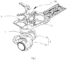
- an embodiment of the present disclosure provides an aerial vehicle 100.
- the aerial vehicle 100 can comprise a quick gimbal connector 1, a vehicle body 2 and an imaging device 3.
- the vehicle body 2 and the imaging device 3 can be respectively connected to opposite sides of the quick gimbal connector 1.
- the quick gimbal connector 1 of the present disclosure can comprise a first cylinder 10, a second cylinder 20, a connecting plate 30 and a connector 40.
- the second cylinder 20 can be coaxially and rotatably connected with the first cylinder 10.
- the connecting plate 30 can be fixedly connected with the second cylinder 20.
- the connector 40 can be detachably mounted between the first cylinder 10 and the second cylinder 20.
- the first cylinder 10 can be a hollow circular cylinder.
- the first cylinder 10 can comprise a first end 11 and a second end 12 which are opposite to each other in an axial direction.
- a side plate 12a can extend from an end face of the second end 12.
- the side plate 12a can have an L-shape.
- the side plate 12a can comprise a horizontal part 121 and a vertical part 122.
- the vertical part 122 can be substantially perpendicular to and connected with the horizontal part 121 and the second end 12.
- the vertical part 122 can be provided with a first boss 122a .
- the first boss 122a can comprise a connecting portion 1221 and a shifting portion 1222.
- the connecting portion 1221 can be provided on an end face of the vertical part 122.
- the connecting portion 1221 can be provided as an arc-shaped rib.
- the shifting portion 1222 can be provided on a periphery of the first cylinder 10 at a central position of the connecting portion 1221.
- the shifting portion 1222 can be a trapezoidal boss which protrudes from the periphery of the first cylinder 10.
- the shifting portion 1222 can be formed integrally with the first cylinder 10.
- the shifting portion 1222 can facilitate a hand holding of the first cylinder 10.
- the shifting portion 1222 can be provided with a through-hole 1222a .
- the through-hole 1222a can be provided at a central portion of the shifting portion 1222.
- At least one bar-shaped protrusion 11a can be provided on an inner wall of the first end 11.
- the bar-shaped protrusion 11a can extend along a circumferential direction of the inner wall of the first end 11.
- three bar-shaped protrusions 11a can be provided on the inner wall of the first end 11, each of which being an arc-shaped bar extending along the inner wall of the first end 11.
- One end of each of the three bar-shaped protrusions 11a can be chamfered to facilitate a connection.
- the three bar-shaped protrusions 11a can comprise one first bar-shaped protrusion 111 and two second bar-shaped protrusions 112.
- a length of the first bar-shaped protrusion 111 can be greater than a length of the second bar-shaped protrusions 112.
- the number of the bar-shaped protrusion 11a can be one, two or four.
- a sliding slot 11b can be formed by the three bar-shaped protrusions 11a and an end face of the horizontal part 121 of the side plate 12.
- the sliding slot 11b can be an arc-shaped slot extending along the circumferential direction of the inner wall of the first end 11.
- the sliding slot 11b can be a circular slot extending along the inner wall of the first end 11.
- At least one entrance 113 can be provided at an end of the sliding slot 11b .
- the entrance 113 can be an arc-shaped slot extending along the circumferential direction of the inner wall of the first end 11.
- three entrances 113 can be provided.
- the three entrances 113 can be formed between every two of the three bar-shaped protrusions 11a.
- three entrances 113 can be formed between every two of the one first bar-shaped protrusion 111 and the two second bar-shaped protrusions 112.
- the three entrances 113 can comprise one first entrance 113a and two second entrances 113b.
- a length of the first entrance can correspond to the length of the first bar-shaped protrusion 111, such that the length of the first entrance is greater than a length of the second entrances.
- the number of the entrance 113 can be one, two or four, and the shape of the entrance 113 can be circular, square or U-shaped.
- the second cylinder 20 can be a hollow circular cylinder.
- the second cylinder 20 can be a flange.
- the second cylinder 20 can be received in the first cylinder 10.
- the second cylinder 20 can be coaxially and rotatably connected with the first cylinder 10.
- the second cylinder 20 can comprise a third end 21 and a fourth end 22 which are disposed opposite to each other in an axial direction.
- the third end 21 can be in an annular ring.
- the third end 21 can be provided on its end face with four threaded holes 211. In some instances, the four threaded holes 211 can form a quadrilateral with respect to an axis of the second cylinder 20.
- Two studs 212 can protrude from an inner wall of the third end 21.
- the two studs 212 can be disposed symmetrically with respect to the axis of the second cylinder 20.
- the two studs 212 can each be provided with a guiding through-hole 212a.
- the two guiding through-holes 212a can provide a guiding when the second cylinder 20 is connected with other components.
- Two first connecting blocks 213 can be further provided on the end face of the third end 21.
- the two first connecting blocks 213 can be disposed symmetrically with respect to a center of the second cylinder 20.
- the two first connecting blocks 213 can be provided adjacent to the two studs 212, respectively.
- the two first connecting blocks 213 can be square blocks.
- the two first connecting blocks 213 can provide a supporting and guiding when the second cylinder 20 is connected with other components.
- Two plunger holes for example, a first plunger hole 214 and a second plunger hole 215, can be provided in a circumferential direction of the third end 21.
- a distance between a center of the first plunger hole 214 and a center of the second plunger hole 215 can be equal to a length of the first boss 122a, so as to facilitate a fitting between the first cylinder 10 and the second cylinder 20.
- the fourth end 22 can be a step surface extending outwardly from the third end 21.
- the fourth end 22 can connect the second cylinder 20 with the first cylinder 10.
- the fourth end 22 can be carried on the end face of the horizontal part 12a of the side plate 12, such that the second cylinder 20 is sleeved in the first cylinder 10 and the second cylinder 20 is prevented from disengaging from the first cylinder 10.
- the first cylinder 10 can rotate around its axis with respect to the second cylinder 20.
- the first cylinder 10 can rotate around its axis when the shifting portion 1222 of the first boss 122a is shifted.
- the connecting plate 30 can be fixedly connected with the second cylinder 20.
- the connecting plate 30 can be a thin plate having a square shape.
- the connecting plate 30 can be fixedly connected with the second cylinder 20 by means of a screw.
- the connecting plate 30 can be provided with four holes 31 which are respectively fitted with the four threaded holes 211 of the second cylinder 20. Screws can each pass through the holes 31 and corresponding threaded holes 211, so as to fixedly connect the connecting plate 30 with the second cylinder 20.
- the connecting plate 30 can comprise a first end face 32 and a second end face 33 which are opposite to each other.
- the first end face 32 can be an end facing toward the second cylinder 20.
- the first end face 32 can be provided with two second connecting blocks (not shown).
- the two second connecting blocks can be disposed symmetrically with respect to a center of the connecting plate 30.
- the two second connecting blocks can be fitted to the two first connecting blocks 213.
- the fitting of the first connecting blocks 213 and the second connecting blocks can provide a supporting and guiding, so as to further tighten a connection between the connecting plate 30 and the second cylinder 20.
- a second boss 32a can be provided on the first end face 32.
- the second boss 32a can be an arc-shaped rib which is provided on the first end face 32.
- the second boss 32a can be fitted with an end face of the vertical part 122 of the side plate 12.
- the second boss 32a can abut against the connecting portion 1221 of the first boss 122a, so as to limit a rotating of the first cylinder 10.
- the first cylinder 10 When the first cylinder 10 is rotated to an extent that the connecting portion 1221 abuts against the second boss 32a , the first cylinder 10 can be stopped by the second boss 32a.
- a signal receiver 33a can be provided on the second end face 33.
- the signal receiver 33a can receive signals from an aerial device which is attached to the connecting plate 30.
- the connector 40 can be detachably connected with the first cylinder 10.
- the connector 40 is in a disk-shaped plate.
- At least one rib 41a can be provided on a periphery of the connector 40.
- the at least one rib 41a can be fitted with the at least one entrance 113, and can enter into or exit from the sliding slot 11b via the at least one entrance 113.
- three ribs 41a can be provided.
- the three ribs 41a can be respectively fitted into the three entrances 113.
- the three ribs 41a each can be an arc-shaped rib provided on the periphery of the connector 40.
- the three ribs 41a can comprise one first rib 411 and two second ribs 412.
- a length of the first rib 411 can be greater than a length of the two second ribs 412, so as to be fitted with the first entrance.
- the first rib 411 can be used to prevent any foolproof in connecting the connector 40 with the first cylinder 10.
- the first rib 411 can be fitted with the first entrance, and the two ribs 412 can be fitted with the two second entrances, so as to prevent any misalignment between the connector 40 and the first cylinder 10.
- an elastic member 41b can be provided on the connector 40.
- the elastic member 41b can be a circular bumper cushion.
- the elastic member 41b can be compressed by the first cylinder 10, such that a strength of connection between the connector 40 and the first cylinder 10 can be improved.
- the elastic member 41b can be bonded to the connector 40.
- the elastic member 41b can be bonded to the connector 40 by a glue.
- a plurality of pillars 413 can be provided uniformly along a periphery of the elastic member 41b, which can increase a friction between the connector 40 and the first cylinder 10.
- the elastic member 41b can be a rubber gasket, a rubber cushion or a silicone cushion.
- the elastic member 41b can be compressed by a pressure from the first cylinder 10, such that the connector 40 is further connected with the first cylinder 10, ensuring a connection tightness there between. Since the elastic member 41b is provided with pillars 413 thereon, the elastic member 41b can be further compressed, such that a friction between the first cylinder 10 and the connector 40 can be increased and thus a strength of connection can be increased. If an aerial device is connected to the connecting plate 30, the aerial device may vibrate due to an air resistance during the flight. In this case, the elastic member 41b can reduce a vibration experienced by the aerial device to smooth a flight of the aerial device.
- the connector 40 can also be provided with two guiding columns 41c.
- the guiding columns 41c can pass through the elastic member 41b and be disposed symmetrically with respect to a center of the elastic member 41b.
- the two guiding columns 41c can pass through the two guiding through-holes 212a of the second cylinder 20, respectively, allowing the connector 40 being linearly connected with the first cylinder 10, thus improving a smoothness in the connecting.
- the connector 40 can be provided with three tabs 41d.
- the tabs 41d can be provided on an end face of the connector 40 which is remote from the elastic member 41b.
- the three tabs 41d each can be an arc-shaped rib extending along a periphery of the connector 40.
- the three ribs 41a can enter into or exit from the sliding slot 11b via the three entrances 113, such that the connector 40 and the first cylinder 10 can be locked or separated.
- the connector 40 is locked with the first cylinder 10.
- the three ribs 41a can slide in the sliding slot 11b to positions corresponding to the three entrances 113.
- the three ribs 41a can exit from the sliding slot 11b via the three entrances 113, such that the connector 40 is separated from the first cylinder 10. Therefore, the connector 40 and the first cylinder 10 can be quickly locked and separated.
- the first direction A can be opposite to the second direction B.
- the first direction A can be a counter-clockwise direction
- the second direction B can be a clockwise direction.
- the first direction A can be a clockwise direction
- the second direction B can be a counter-clockwise direction.
- the quick gimbal connector 1 can comprise a plunger 50 which is provided at the shifting portion 1222.
- the plunger 50 can be provided in the through-hole 1222a.
- the plunger 50 can comprise a tip portion 51.
- the tip portion 51 can be provided in spherical structure.
- the connector 40 can be locked with the first cylinder 10, the tip portion 51 can be fitted into the first plunger hole 214 and a sound can be generated.
- the user can thus easily determine the locked state between the connector 40 and the first cylinder 10, such that the user's experience is improved.
- the connector 40 can be separated from the first cylinder 10, the tip portion 51 can be fitted into the second plunger hole 215 and a sound can be generated.
- the user can thus easily determine the separated condition between the first cylinder 10 and the connector 40. Since a sound is generated when the plunger 50 is fitted into the first plunger hole 214 or the second plunger hole 215, the user can experience an improved operation when shifting the shifting portion 1222, thereby improving the user experience in operating the device of the present disclosure.
- the quick gimbal connector 1 can comprise an adaptor 60 which is connected with the connector 40.
- the adaptor 60 can comprise an adapting plate 61 and a housing 62.
- the adapting plate 61 can be connected with the connector 40, and the housing 62 can be connected with the adapting plate 61.
- the adapting plate 61 can be a circular plate.
- the adapting plate 61 can be snapped with the connector 40 for an easy detachment.
- Three snap slots 61a can be provided to the adapting plate 61 in correspondence to the connector 40.
- Each one of the snap slots 61a can be an arc-shaped slot.
- the three snap slots 61a can be snapped with the three tabs 41d, respectively, such that adapting plate 61 can be easily connected with the connector 40.
- the adapting plate 61 can be connected with the connector 40 by other means such as a threaded connection, a soldering connection or a screwed connection.
- the adaptor 60 can comprise a housing 62.
- the housing 62 can be connected with the adapting plate 61 by a threaded connection.
- the housing 62 can be provided with an inner thread (not shown), while the adapting plate 61 can be provided with a corresponding outer thread, such that the housing 62 can be connected with the adapting plate 61 by a threaded connection.
- a rotating shaft 62a can be provided within the housing 62.
- the rotating shaft 62a can be provided at a central position of the housing 62.
- the rotating shaft 62a can drive a rotation of those components which are connected to the housing 62.
- a rotation arm 62b can be provided on a periphery of the housing 62.
- the rotation arm 62b can be formed integrally with the housing 62 for an easy manufacturing.
- the rotation arm 62a can comprise one end provided on the periphery of the housing 62, and another end connected with other components such as an imaging device.
- An electrical box 63 can be received in a receiving cavity of the housing 62.
- the electrical box 63 can accommodate a flexible printed circuit (FPC) flat cable 63a.
- An end of the FPC flat cable 63a can be wound around the rotating shaft 62a.
- the FPC flat cable 63a can rotate as the rotating shaft 62 rotates.
- the vehicle body 2 can be connected to an end of the quick gimbal connector 1.
- the vehicle body 2 can comprise a connecting bracket 21 and a signal transmitter (not shown).
- the connecting bracket 21 can be fixedly connected with the connecting plate 30.
- the signal transmitter can be provided within the connecting bracket 21.
- the connecting bracket 21 can be fixedly connected with the connecting plate 30 by means of a screw for an easy detachment. If the imaging device 3 is not to be carried by the aerial vehicle 100, the user can rotate the quick gimbal connector 1 to an extend that the first boss 122a abuts against the second boss 32a and the three ribs 41a exit from the sliding slot 11b via the three entrances 113, such that the connector 40 can be separated from the first cylinder 10, and the imaging device 3 can be separated from the vehicle body 2. In this way, the imaging device can be quickly attached to or detached from the aerial vehicle, and an adaptability of the product can be improved satisfy user's requirements.
- the signal transmitter can be provided at an end of the connecting bracket 21 proximal to the signal receiver 33a, so as to facilitate a transmission of the signal to the signal receiver 33a .
- the imaging device 3 can be rotatably connected to an end of the quick gimbal connector 1 remote from the vehicle body 2. In some instances, the imaging device 3 can be rotatably connected to the rotation arm 62a.
- the imaging device 3 can comprise a camera 3a and a rotation shaft 3b.
- the rotation shaft 3b can be rotatably connected to the rotation arm 62a.
- the camera 3a can be rotated as the rotation arm 62 rotates, such that the camera 3a can capture images from various orientations.
- the quick gimbal connector of the present disclosure provides at least one entrance on the first cylinder and corresponding at least one rib on the connector.
- a position limitation is implemented by a mating of the first boss and the second boss.
- the at least one rib can enter into and exit from the sliding slot via the at least one entrance, such that the first cylinder and the connector can be locked or separated.
- a quick connection between the first cylinder and the connector can be realized.
- a utilization of the product and the user's experience can be improved by a simple configuration of the present disclosure.
Landscapes
- Engineering & Computer Science (AREA)
- General Engineering & Computer Science (AREA)
- Mechanical Engineering (AREA)
- Aviation & Aerospace Engineering (AREA)
- Remote Sensing (AREA)
- Microelectronics & Electronic Packaging (AREA)
- Physics & Mathematics (AREA)
- General Physics & Mathematics (AREA)
- Accessories Of Cameras (AREA)
- Details Of Connecting Devices For Male And Female Coupling (AREA)
- Studio Devices (AREA)
- Coupling Device And Connection With Printed Circuit (AREA)
- Forklifts And Lifting Vehicles (AREA)
Abstract
Description
- The present disclosure relates to aerial vehicles, and in particular to a quick gimbal connectors and an aerial vehicle having the quick gimbal connector.
- The existing gimbals are generally fixed to the aerial vehicles by means of screws. However, a client can determine if a gimbal is to be installed in view of his/her actual requirements. If the gimbal is to be detached from the aerial vehicle, a tool is required because the gimbal cannot be manually detached. Therefore, there is a need to provide a quick connector which enables a quick detachment of a gimbal from an aerial vehicle.
- The object of the present disclosure is to provide a quick connector which enables a quick detachment of a gimbal from an aerial vehicle.
- In view of above discussed technical problem, a first aspect of the present disclosure provides a quick gimbal connector. The quick gimbal connector can comprise: a first cylinder comprising a first end and a second end which are opposite to each other in an axial direction; a sliding slot being provided on an inner wall of the first end and extending along a circumferential direction of the inner wall, at least one entrance being provided at an end portion of the sliding slot, and a first boss being provided on an end face of the second end; a second cylinder coaxially and rotatably connected with the first cylinder; a connector detachably mounted between the first cylinder and the second cylinder; at least one rib being provided on a periphery of the connector, the at least one rib being configured to fit with the at least one entrance; and a connecting plate fixedly connected with the second cylinder; the connecting plate being connecting with an aerial device, a second boss being provided at a connection between the connecting plate and the second cylinder, and the second boss being configured to abut against the first boss to limit a rotating of the first cylinder. The at least one rib is configured to enter into or exist from the sliding slot via the at least one entrance when the first cylinder is rotated to an extent that the first boss abuts against the second boss, so as to lock the connector with the first cylinder or separate the connector from the first cylinder.
- In some embodiments, a side plate can extend from the second end, the side plate can comprise a horizontal part and a vertical part; the first boss can comprise a connecting portion and a shifting portion, the connecting portion can be provided on an end face of the vertical part and can be an arc-shaped rib, the shifting portion can be provided on a periphery of the first cylinder and can be located at a center of the connecting portion; and the first cylinder can rotate around its axis when the shifting portion is shifted.
- In some embodiments, a through-hole can be provided at a center of the shifting portion, a plunger can be provided in the through-hole; two plunger holes can be provided on the periphery of the second cylinder, a distance between centers of the two plunger holes can be equal to a length of the connecting portion; when the first cylinder rotates to an extent that the first boss abuts against the second boss, the plunger can be fitted into one of the plunger holes.
- In some embodiments, a step surface can extend from the second cylinder, the step surface can be carried on an end face of the horizontal part of the side plate; the step surface can connect the second cylinder with the first cylinder such that the second cylinder is sleeved in the first cylinder.
- In some embodiments, the second boss can be an arc-shaped bar provided on the connecting plate, and the second boss can be fitted with an end face of the vertical part of the side plate.
- In some embodiments, the quick gimbal connector can further comprise three entrances, the three entrances can be provided on an end portion of the sliding slot which is proximal to the first end, and the connector can be provided with three said ribs which are respectively fitted into the three entrances.
- In some embodiments, the inner wall of the first end can be provided with three bar-shaped protrusions which are arranged as a triangle with respect to the axis of the first cylinder; each one of the three bar-shaped protrusions can be an arc-shaped bar, the sliding slot can be formed by the three bar-shaped protrusions and the end face of the horizontal part; the three entrances can be formed between the three bar-shaped protrusions, and the three entrances can be fitted with the three ribs.
- In some embodiments, each one of the three ribs can be an arc-shaped rib provided on the periphery of the connector; the three ribs can comprise one first rib and two second ribs, a length of the first rib can be greater than a length of the second rib; and the first rib can prevent a foolproof in connecting the connector with the first cylinder.
- In some embodiments, the connecting plate can be provided with a signal receiver, the signal receiver can receive a signal from the aerial device which is connected to the connecting plate.
- In some embodiments, the quick gimbal connector can comprise an elastic member which is elastically connected between the connector and the first cylinder in the axial direction.
- In some embodiments, the elastic member can be a bumper cushion which is compressed by the first cylinder while connecting the connector with the first cylinder.
- In some embodiments, wherein the connector can be provided with two guiding columns, the guiding columns passing through the elastic member and being disposed symmetrically with respect to a center of the elastic member; and the second cylinder can be provided with two guiding holes, the two guiding columns passing through the two guiding holes.
- A second aspect of the present disclosure provides an aerial vehicle, comprising: a vehicle body; a quick gimbal connector as described hereinabove; and an imaging device, wherein the vehicle body and the imaging device are respectively connected to two ends of the quick gimbal connector.
- The quick gimbal connector of the present disclosure provides at least one entrance on the first cylinder and corresponding at least one rib on the connector. A position limitation is implemented by a mating of the first boss and the second boss. The at least one rib can enter into and exit from the sliding slot via the at least one entrance, such that the first cylinder and the connector can be locked or separated. A quick connection between the first cylinder and the connector can be realized. A utilization of the product and the user's experience can be improved by a simple configuration of the present disclosure.
- Brief description of the drawings will be provided in order to describe the technical solutions of the present disclosure. It will be appreciated the configuration described with reference to the drawings is merely illustrative. Those skilled in the art can conceive other drawings on basis of the appended drawings without creative efforts.
-
Fig. 1 is a schematic diagram of an aerial vehicle according to an embodiment of the present disclosure. -
Fig. 2 is an exploded schematic diagram of a quick gimbal connector according to an embodiment of the present disclosure. -
Fig. 3 is a schematic diagram of a first cylinder according to an embodiment of the present disclosure. -
Fig. 4 is a schematic diagram of a connector according to an embodiment of the present disclosure. -
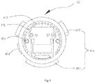
Fig. 5 is a schematic diagram showing an assembly of the quick gimbal connector according to an embodiment of the present disclosure. -
Fig. 6 is a partially cross-sectional view along VI direction inFig. 5 . - The technical solutions of embodiments of the present disclosure will be described with reference to the appended drawings.
- Referring to
Fig.1 , an embodiment of the present disclosure provides anaerial vehicle 100. Theaerial vehicle 100 can comprise aquick gimbal connector 1, avehicle body 2 and animaging device 3. Thevehicle body 2 and theimaging device 3 can be respectively connected to opposite sides of thequick gimbal connector 1. - Referring to
Figs. 2 to 6 , thequick gimbal connector 1 of the present disclosure can comprise afirst cylinder 10, asecond cylinder 20, a connectingplate 30 and aconnector 40. Thesecond cylinder 20 can be coaxially and rotatably connected with thefirst cylinder 10. The connectingplate 30 can be fixedly connected with thesecond cylinder 20. Theconnector 40 can be detachably mounted between thefirst cylinder 10 and thesecond cylinder 20. - The
first cylinder 10 can be a hollow circular cylinder. Thefirst cylinder 10 can comprise afirst end 11 and asecond end 12 which are opposite to each other in an axial direction. Aside plate 12a can extend from an end face of thesecond end 12. In some instances, theside plate 12a can have an L-shape. For instance, theside plate 12a can comprise ahorizontal part 121 and avertical part 122. Thevertical part 122 can be substantially perpendicular to and connected with thehorizontal part 121 and thesecond end 12. Thevertical part 122 can be provided with a first boss 122a. The first boss 122a can comprise a connectingportion 1221 and a shiftingportion 1222. The connectingportion 1221 can be provided on an end face of thevertical part 122. In some instances, the connectingportion 1221 can be provided as an arc-shaped rib. The shiftingportion 1222 can be provided on a periphery of thefirst cylinder 10 at a central position of the connectingportion 1221. The shiftingportion 1222 can be a trapezoidal boss which protrudes from the periphery of thefirst cylinder 10. The shiftingportion 1222 can be formed integrally with thefirst cylinder 10. The shiftingportion 1222 can facilitate a hand holding of thefirst cylinder 10. The shiftingportion 1222 can be provided with a through-hole 1222a. The through-hole 1222a can be provided at a central portion of the shiftingportion 1222. - At least one bar-
shaped protrusion 11a can be provided on an inner wall of thefirst end 11. The bar-shapedprotrusion 11a can extend along a circumferential direction of the inner wall of thefirst end 11. In some embodiments, three bar-shapedprotrusions 11a can be provided on the inner wall of thefirst end 11, each of which being an arc-shaped bar extending along the inner wall of thefirst end 11. One end of each of the three bar-shapedprotrusions 11a can be chamfered to facilitate a connection. The three bar-shapedprotrusions 11a can comprise one first bar-shapedprotrusion 111 and two second bar-shapedprotrusions 112. A length of the first bar-shapedprotrusion 111 can be greater than a length of the second bar-shapedprotrusions 112. Alternatively, the number of the bar-shapedprotrusion 11a can be one, two or four. - A sliding
slot 11b can be formed by the three bar-shapedprotrusions 11a and an end face of thehorizontal part 121 of theside plate 12. The slidingslot 11b can be an arc-shaped slot extending along the circumferential direction of the inner wall of thefirst end 11. In some embodiments, the slidingslot 11b can be a circular slot extending along the inner wall of thefirst end 11. - At least one
entrance 113 can be provided at an end of the slidingslot 11b. Theentrance 113 can be an arc-shaped slot extending along the circumferential direction of the inner wall of thefirst end 11. In some embodiments, threeentrances 113 can be provided. The threeentrances 113 can be formed between every two of the three bar-shapedprotrusions 11a. In other words, threeentrances 113 can be formed between every two of the one first bar-shapedprotrusion 111 and the two second bar-shapedprotrusions 112. The threeentrances 113 can comprise one first entrance 113a and twosecond entrances 113b. A length of the first entrance can correspond to the length of the first bar-shapedprotrusion 111, such that the length of the first entrance is greater than a length of the second entrances. Alternatively, the number of theentrance 113 can be one, two or four, and the shape of theentrance 113 can be circular, square or U-shaped. - In some embodiments, the
second cylinder 20 can be a hollow circular cylinder. Thesecond cylinder 20 can be a flange. Thesecond cylinder 20 can be received in thefirst cylinder 10. Thesecond cylinder 20 can be coaxially and rotatably connected with thefirst cylinder 10. Thesecond cylinder 20 can comprise athird end 21 and afourth end 22 which are disposed opposite to each other in an axial direction. Thethird end 21 can be in an annular ring. Thethird end 21 can be provided on its end face with four threaded holes 211. In some instances, the four threaded holes 211 can form a quadrilateral with respect to an axis of thesecond cylinder 20. Twostuds 212 can protrude from an inner wall of thethird end 21. The twostuds 212 can be disposed symmetrically with respect to the axis of thesecond cylinder 20. The twostuds 212 can each be provided with a guiding through-hole 212a. The two guiding through-holes 212a can provide a guiding when thesecond cylinder 20 is connected with other components. Two first connectingblocks 213 can be further provided on the end face of thethird end 21. The two first connectingblocks 213 can be disposed symmetrically with respect to a center of thesecond cylinder 20. The two first connectingblocks 213 can be provided adjacent to the twostuds 212, respectively. The two first connectingblocks 213 can be square blocks. The two first connectingblocks 213 can provide a supporting and guiding when thesecond cylinder 20 is connected with other components. - Two plunger holes, for example, a
first plunger hole 214 and asecond plunger hole 215, can be provided in a circumferential direction of thethird end 21. A distance between a center of thefirst plunger hole 214 and a center of thesecond plunger hole 215 can be equal to a length of the first boss 122a, so as to facilitate a fitting between thefirst cylinder 10 and thesecond cylinder 20. - The
fourth end 22 can be a step surface extending outwardly from thethird end 21. Thefourth end 22 can connect thesecond cylinder 20 with thefirst cylinder 10. When thesecond cylinder 20 is sleeved in thefirst cylinder 10, thefourth end 22 can be carried on the end face of thehorizontal part 12a of theside plate 12, such that thesecond cylinder 20 is sleeved in thefirst cylinder 10 and thesecond cylinder 20 is prevented from disengaging from thefirst cylinder 10. Furthermore, thefirst cylinder 10 can rotate around its axis with respect to thesecond cylinder 20. - In some instances, the
first cylinder 10 can rotate around its axis when the shiftingportion 1222 of the first boss 122a is shifted. - The connecting
plate 30 can be fixedly connected with thesecond cylinder 20. The connectingplate 30 can be a thin plate having a square shape. In some instances, the connectingplate 30 can be fixedly connected with thesecond cylinder 20 by means of a screw. In some embodiments, the connectingplate 30 can be provided with fourholes 31 which are respectively fitted with the four threaded holes 211 of thesecond cylinder 20. Screws can each pass through theholes 31 and corresponding threaded holes 211, so as to fixedly connect the connectingplate 30 with thesecond cylinder 20. - The connecting
plate 30 can comprise afirst end face 32 and asecond end face 33 which are opposite to each other. Thefirst end face 32 can be an end facing toward thesecond cylinder 20. Thefirst end face 32 can be provided with two second connecting blocks (not shown). The two second connecting blocks can be disposed symmetrically with respect to a center of the connectingplate 30. The two second connecting blocks can be fitted to the two first connectingblocks 213. When the connectingplate 30 is fixedly connected with thesecond cylinder 20, the two first connectingblocks 213 can be fitted to the two second connecting blocks. The fitting of the first connectingblocks 213 and the second connecting blocks can provide a supporting and guiding, so as to further tighten a connection between the connectingplate 30 and thesecond cylinder 20. - A
second boss 32a can be provided on thefirst end face 32. Thesecond boss 32a can be an arc-shaped rib which is provided on thefirst end face 32. Thesecond boss 32a can be fitted with an end face of thevertical part 122 of theside plate 12. Thesecond boss 32a can abut against the connectingportion 1221 of the first boss 122a, so as to limit a rotating of thefirst cylinder 10. When thefirst cylinder 10 is rotated to an extent that the connectingportion 1221 abuts against thesecond boss 32a, thefirst cylinder 10 can be stopped by thesecond boss 32a. - A signal receiver 33a can be provided on the
second end face 33. The signal receiver 33a can receive signals from an aerial device which is attached to the connectingplate 30. - The
connector 40 can be detachably connected with thefirst cylinder 10. In some embodiments, theconnector 40 is in a disk-shaped plate. At least onerib 41a can be provided on a periphery of theconnector 40. The at least onerib 41a can be fitted with the at least oneentrance 113, and can enter into or exit from the slidingslot 11b via the at least oneentrance 113. In some instances, threeribs 41a can be provided. The threeribs 41a can be respectively fitted into the threeentrances 113. - In some instances, the three
ribs 41a each can be an arc-shaped rib provided on the periphery of theconnector 40. The threeribs 41a can comprise onefirst rib 411 and twosecond ribs 412. A length of thefirst rib 411 can be greater than a length of the twosecond ribs 412, so as to be fitted with the first entrance. Thefirst rib 411 can be used to prevent any foolproof in connecting theconnector 40 with thefirst cylinder 10. - In connecting the
connector 40 with thefirst cylinder 10, thefirst rib 411 can be fitted with the first entrance, and the tworibs 412 can be fitted with the two second entrances, so as to prevent any misalignment between theconnector 40 and thefirst cylinder 10. - In some embodiments, an
elastic member 41b can be provided on theconnector 40. In some instances, theelastic member 41b can be a circular bumper cushion. In connecting theconnector 40 with thefirst cylinder 10, theelastic member 41b can be compressed by thefirst cylinder 10, such that a strength of connection between theconnector 40 and thefirst cylinder 10 can be improved. Theelastic member 41b can be bonded to theconnector 40. For instance, theelastic member 41b can be bonded to theconnector 40 by a glue. A plurality ofpillars 413 can be provided uniformly along a periphery of theelastic member 41b, which can increase a friction between theconnector 40 and thefirst cylinder 10. Alternatively, theelastic member 41b can be a rubber gasket, a rubber cushion or a silicone cushion. - In connecting the
connector 40 with thefirst cylinder 10, theelastic member 41b can be compressed by a pressure from thefirst cylinder 10, such that theconnector 40 is further connected with thefirst cylinder 10, ensuring a connection tightness there between. Since theelastic member 41b is provided withpillars 413 thereon, theelastic member 41b can be further compressed, such that a friction between thefirst cylinder 10 and theconnector 40 can be increased and thus a strength of connection can be increased. If an aerial device is connected to the connectingplate 30, the aerial device may vibrate due to an air resistance during the flight. In this case, theelastic member 41b can reduce a vibration experienced by the aerial device to smooth a flight of the aerial device. - The
connector 40 can also be provided with two guidingcolumns 41c. The guidingcolumns 41c can pass through theelastic member 41b and be disposed symmetrically with respect to a center of theelastic member 41b. The two guidingcolumns 41c can pass through the two guiding through-holes 212a of thesecond cylinder 20, respectively, allowing theconnector 40 being linearly connected with thefirst cylinder 10, thus improving a smoothness in the connecting. - The
connector 40 can be provided with threetabs 41d. Thetabs 41d can be provided on an end face of theconnector 40 which is remote from theelastic member 41b. The threetabs 41d each can be an arc-shaped rib extending along a periphery of theconnector 40. - When the
first cylinder 10 is rotated to an extent that the connectingportion 1221 of the first boss 122a abuts against thesecond boss 32a, the threeribs 41a can enter into or exit from the slidingslot 11b via the threeentrances 113, such that theconnector 40 and thefirst cylinder 10 can be locked or separated. - In some embodiments, when the three
ribs 41a are located in the slidingslot 11b and thefirst cylinder 10 is rotated in a first direction A to an extent that the first boss 122a abuts against thesecond boss 32a, theconnector 40 is locked with thefirst cylinder 10. - When the
first cylinder 10 is rotated in a second direction B to an extent that the first boss 122a abuts against thesecond boss 32a, the threeribs 41a can slide in the slidingslot 11b to positions corresponding to the threeentrances 113. The threeribs 41a can exit from the slidingslot 11b via the threeentrances 113, such that theconnector 40 is separated from thefirst cylinder 10. Therefore, theconnector 40 and thefirst cylinder 10 can be quickly locked and separated. - The first direction A can be opposite to the second direction B. In some embodiments, as seen from the view point illustrated in
Fig. 5 , the first direction A can be a counter-clockwise direction, and the second direction B can be a clockwise direction. Alternatively, the first direction A can be a clockwise direction, while the second direction B can be a counter-clockwise direction. - The
quick gimbal connector 1 can comprise aplunger 50 which is provided at the shiftingportion 1222. In some embodiments, theplunger 50 can be provided in the through-hole 1222a. Theplunger 50 can comprise atip portion 51. In some instances, thetip portion 51 can be provided in spherical structure. When thefirst cylinder 10 is rotated to an extent that the first boss 122a abuts against thesecond boss 32a, thetip portion 51 of theplunger 50 can be fitted into thefirst plunger hole 214 or thesecond plunger hole 215. - In some instances, when the
first cylinder 10 is rotated in the first direction A to an extent that the first boss 122a abuts against thesecond boss 32a, theconnector 40 can be locked with thefirst cylinder 10, thetip portion 51 can be fitted into thefirst plunger hole 214 and a sound can be generated. The user can thus easily determine the locked state between theconnector 40 and thefirst cylinder 10, such that the user's experience is improved. When thefirst cylinder 10 is rotated in the second direction B to an extent that the first boss 122a abuts against thesecond boss 32a, theconnector 40 can be separated from thefirst cylinder 10, thetip portion 51 can be fitted into thesecond plunger hole 215 and a sound can be generated. The user can thus easily determine the separated condition between thefirst cylinder 10 and theconnector 40. Since a sound is generated when theplunger 50 is fitted into thefirst plunger hole 214 or thesecond plunger hole 215, the user can experience an improved operation when shifting the shiftingportion 1222, thereby improving the user experience in operating the device of the present disclosure. - The
quick gimbal connector 1 can comprise anadaptor 60 which is connected with theconnector 40. In some instances, theadaptor 60 can comprise an adaptingplate 61 and ahousing 62. The adaptingplate 61 can be connected with theconnector 40, and thehousing 62 can be connected with the adaptingplate 61. - In some embodiments, the adapting
plate 61 can be a circular plate. The adaptingplate 61 can be snapped with theconnector 40 for an easy detachment. Three snap slots 61a can be provided to the adaptingplate 61 in correspondence to theconnector 40. Each one of the snap slots 61a can be an arc-shaped slot. The three snap slots 61a can be snapped with the threetabs 41d, respectively, such that adaptingplate 61 can be easily connected with theconnector 40. Alternatively, the adaptingplate 61 can be connected with theconnector 40 by other means such as a threaded connection, a soldering connection or a screwed connection. - The
adaptor 60 can comprise ahousing 62. Thehousing 62 can be connected with the adaptingplate 61 by a threaded connection. In some embodiments, thehousing 62 can be provided with an inner thread (not shown), while the adaptingplate 61 can be provided with a corresponding outer thread, such that thehousing 62 can be connected with the adaptingplate 61 by a threaded connection. A rotating shaft 62a can be provided within thehousing 62. The rotating shaft 62a can be provided at a central position of thehousing 62. The rotating shaft 62a can drive a rotation of those components which are connected to thehousing 62. - A
rotation arm 62b can be provided on a periphery of thehousing 62. Therotation arm 62b can be formed integrally with thehousing 62 for an easy manufacturing. The rotation arm 62a can comprise one end provided on the periphery of thehousing 62, and another end connected with other components such as an imaging device. - An
electrical box 63 can be received in a receiving cavity of thehousing 62. Theelectrical box 63 can accommodate a flexible printed circuit (FPC) flat cable 63a. An end of the FPC flat cable 63a can be wound around the rotating shaft 62a. The FPC flat cable 63a can rotate as the rotatingshaft 62 rotates. - Referring to
Fig.1 , thevehicle body 2 can be connected to an end of thequick gimbal connector 1. Thevehicle body 2 can comprise a connectingbracket 21 and a signal transmitter (not shown). The connectingbracket 21 can be fixedly connected with the connectingplate 30. The signal transmitter can be provided within the connectingbracket 21. - In some embodiments, the connecting
bracket 21 can be fixedly connected with the connectingplate 30 by means of a screw for an easy detachment. If theimaging device 3 is not to be carried by theaerial vehicle 100, the user can rotate thequick gimbal connector 1 to an extend that the first boss 122a abuts against thesecond boss 32a and the threeribs 41a exit from the slidingslot 11b via the threeentrances 113, such that theconnector 40 can be separated from thefirst cylinder 10, and theimaging device 3 can be separated from thevehicle body 2. In this way, the imaging device can be quickly attached to or detached from the aerial vehicle, and an adaptability of the product can be improved satisfy user's requirements. - In sense of signal transmission, the signal transmitter can be provided at an end of the connecting
bracket 21 proximal to the signal receiver 33a, so as to facilitate a transmission of the signal to the signal receiver 33a. - The
imaging device 3 can be rotatably connected to an end of thequick gimbal connector 1 remote from thevehicle body 2. In some instances, theimaging device 3 can be rotatably connected to the rotation arm 62a. Theimaging device 3 can comprise a camera 3a and arotation shaft 3b. Therotation shaft 3b can be rotatably connected to the rotation arm 62a. The camera 3a can be rotated as therotation arm 62 rotates, such that the camera 3a can capture images from various orientations. - The quick gimbal connector of the present disclosure provides at least one entrance on the first cylinder and corresponding at least one rib on the connector. A position limitation is implemented by a mating of the first boss and the second boss. The at least one rib can enter into and exit from the sliding slot via the at least one entrance, such that the first cylinder and the connector can be locked or separated. A quick connection between the first cylinder and the connector can be realized. A utilization of the product and the user's experience can be improved by a simple configuration of the present disclosure.
- The foregoing disclosure is merely illustrative of the embodiments of the disclosure but not intended to limit the scope of the disclosure. Any equivalent modifications to a structure or process, which are made without departing from the specification and the drawings of the disclosure, shall also fall into the scope of the disclosure.
Claims (13)
- A quick gimbal connector, comprising:a first cylinder comprising:a first end and a second end which are opposite to each other in an axial direction;a sliding slot being provided on an inner wall of the first end and extending along a circumferential direction of the inner wall;at least one entrance being provided at an end portion of the sliding slot; anda first boss being provided on an end face of the second end;a second cylinder coaxially and rotatably connected with the first cylinder;a connector detachably mounted between the first cylinder and the second cylinder;at least one rib being provided on a periphery of the connector, the at least one rib being configured to fit with the at least one entrance;a connecting plate fixedly connected with the second cylinder, the connecting plate being configured to connect with an aerial device; anda second boss being provided at a connection between the connecting plate and the second cylinder, the second boss being configured to abut against the first boss to limit a rotating of the first cylinder,wherein the at least one rib is configured to enter into or exist from the sliding slot via the at least one entrance when the first cylinder is rotated to an extent that the first boss abuts against the second boss, so as to lock the connector with the first cylinder or separate the connector from the first cylinder.
- The quick gimbal connector of claim 1, wherein a side plate extends from the second end, the side plate comprises a horizontal part and a vertical part; the first boss comprises a connecting portion and a shifting portion, the connecting portion is provided on an end face of the vertical part and is an arc-shaped rib, the shifting portion is provided on a periphery of the first cylinder and is located at a center of the connecting portion; and the first cylinder rotates around its axis when the shifting portion is shifted.
- The quick gimbal connector of claim 2, wherein a through-hole is provided at a center of the shifting portion, a plunger is provided in the through-hole; two plunger holes are provided on a periphery of the second cylinder, a distance between centers of the two plunger holes is equal to a length of the connecting portion; when the first cylinder rotates to an extent that the first boss abuts against the second boss, the plunger is fitted into one of the plunger holes.
- The quick gimbal connector of claim 2, wherein a step surface extends from the second cylinder, the step surface is carried on an end face of the horizontal part of the side plate; the step surface connects the second cylinder with the first cylinder such that the second cylinder is sleeved in the first cylinder.
- The quick gimbal connector of claim 2, wherein the second boss is an arc-shaped bar provided on the connecting plate, and the second boss is fitted with an end face of the vertical part of the side plate.
- The quick gimbal connector of claim 2, wherein the quick gimbal connector further comprises three entrances, the three entrances are provided on an end portion of the sliding slot which is proximal to the first end, and the connector is provided with three said ribs which are respectively fitted into the three entrances.
- The quick gimbal connector of claim 6, wherein the inner wall of the first end is provided with three bar-shaped protrusions which are arranged as a triangle with respect to the axis of the first cylinder; each one of the three bar-shaped protrusions is an arc-shaped bar, the sliding slot is formed by the three bar-shaped protrusions and the end face of the horizontal part; the three entrances are formed between the three bar-shaped protrusions, and the three entrances are fitted with the three ribs.
- The quick gimbal connector of claim 7, wherein each one of the three ribs is an arc-shaped rib provided on the periphery of the connector; the three ribs comprise one first rib and two second ribs, a length of the first rib being greater than a length of the second rib; and the first rib prevents a foolproof in connecting the connector with the first cylinder.
- The quick gimbal connector of claim 1, wherein the connecting plate is provided with a signal receiver, the signal receiver receives a signal from the aerial device which is connected to the connecting plate.
- The quick gimbal connector of claim 1, wherein the quick gimbal connector comprises an elastic member which is elastically connected between the connector and the first cylinder in the axial direction.
- The quick gimbal connector of claim 10, wherein the elastic member is a bumper cushion which is compressed by the first cylinder while connecting the connector with the first cylinder.
- The quick gimbal connector of claim 11, wherein the connector is provided with two guiding columns, the guiding columns passing through the elastic member and being disposed symmetrically with respect to a center of the elastic member; and the second cylinder is provided with two guiding holes, the two guiding columns passing through the two guiding holes.
- An aerial vehicle, comprising:a vehicle body;an imaging device; anda quick gimbal connector, comprising:a first cylinder comprising:a first end and a second end which are opposite to each other in an axial direction;a sliding slot being provided on an inner wall of the first end and extending along a circumferential direction of the inner wall;at least one entrance being provided at an end portion of the sliding slot; anda first boss being provided on an end face of the second end;a second cylinder coaxially and rotatably connected with the first cylinder;a connector detachably mounted between the first cylinder and the second cylinder;at least one rib being provided on a periphery of the connector, the at least one rib being configured to fit with the at least one entrance;a connecting plate fixedly connected with the second cylinder, the connecting plate being configured to connect with an aerial device; anda second boss being provided at a connection between the connecting plate and the second cylinder, the second boss being configured to abut against the first boss to limit a rotating of the first cylinder,wherein the at least one rib is configured to enter into or exist from the sliding slot via the at least one entrance when the first cylinder is rotated to an extent that the first boss abuts against the second boss, so as to lock the connector with the first cylinder or separate the connector from the first cylinder,wherein the vehicle body and the imaging device are respectively connected to two ends of the quick gimbal connector.
Priority Applications (1)
| Application Number | Priority Date | Filing Date | Title |
|---|---|---|---|
| EP18198002.0A EP3450814B1 (en) | 2014-07-07 | 2014-07-07 | A quick gimbal connector and an aerial vehicle |
Applications Claiming Priority (1)
| Application Number | Priority Date | Filing Date | Title |
|---|---|---|---|
| PCT/CN2014/081760 WO2016004567A1 (en) | 2014-07-07 | 2014-07-07 | Fast cradle head inserting device and aircraft |
Related Child Applications (2)
| Application Number | Title | Priority Date | Filing Date |
|---|---|---|---|
| EP18198002.0A Division EP3450814B1 (en) | 2014-07-07 | 2014-07-07 | A quick gimbal connector and an aerial vehicle |
| EP18198002.0A Division-Into EP3450814B1 (en) | 2014-07-07 | 2014-07-07 | A quick gimbal connector and an aerial vehicle |
Publications (3)
| Publication Number | Publication Date |
|---|---|
| EP3168519A1 true EP3168519A1 (en) | 2017-05-17 |
| EP3168519A4 EP3168519A4 (en) | 2017-08-02 |
| EP3168519B1 EP3168519B1 (en) | 2018-11-14 |
Family
ID=55063472
Family Applications (2)
| Application Number | Title | Priority Date | Filing Date |
|---|---|---|---|
| EP14897152.6A Not-in-force EP3168519B1 (en) | 2014-07-07 | 2014-07-07 | Fast cradle head inserting device and aircraft |
| EP18198002.0A Active EP3450814B1 (en) | 2014-07-07 | 2014-07-07 | A quick gimbal connector and an aerial vehicle |
Family Applications After (1)
| Application Number | Title | Priority Date | Filing Date |
|---|---|---|---|
| EP18198002.0A Active EP3450814B1 (en) | 2014-07-07 | 2014-07-07 | A quick gimbal connector and an aerial vehicle |
Country Status (5)
| Country | Link |
|---|---|
| US (1) | US9890900B2 (en) |
| EP (2) | EP3168519B1 (en) |
| JP (1) | JP6045759B1 (en) |
| CN (2) | CN107719682B (en) |
| WO (1) | WO2016004567A1 (en) |
Cited By (1)
| Publication number | Priority date | Publication date | Assignee | Title |
|---|---|---|---|---|
| WO2023141667A1 (en) * | 2022-01-25 | 2023-08-03 | Ninjawerk Gmbh | Holding device, and arrangement comprising said holding device |
Families Citing this family (15)
| Publication number | Priority date | Publication date | Assignee | Title |
|---|---|---|---|---|
| US7658556B2 (en) | 2005-01-07 | 2010-02-09 | Joseph Johnson | Panoramic camera mount |
| CN104885342B (en) * | 2014-07-07 | 2018-02-02 | 深圳市大疆灵眸科技有限公司 | Stopping means and use its aircraft |
| CN107719682B (en) * | 2014-07-07 | 2020-10-16 | 深圳市大疆灵眸科技有限公司 | Quick plug-in connection device of cloud platform and aircraft |
| CN105517903B (en) * | 2014-09-24 | 2017-06-23 | 深圳市大疆灵眸科技有限公司 | Cloud platform and imaging device used therefor, and unmanned aerial vehicle |
| CN109723956A (en) * | 2015-08-10 | 2019-05-07 | 深圳市大疆灵眸科技有限公司 | Clamp structure and holder with the clamp structure |
| USD798943S1 (en) * | 2016-04-15 | 2017-10-03 | Sz Dji Osmo Technology Co., Ltd. | Handle with gimbal for camera or the like |
| CN106794902B (en) * | 2016-10-18 | 2020-10-27 | 深圳市大疆灵眸科技有限公司 | Connecting device and drone with the connecting device |
| CN108569413B (en) * | 2017-03-09 | 2024-08-06 | 昆山合朗航空科技有限公司 | Quick-dismantling structure and cradle head |
| CN106931284B (en) * | 2017-03-13 | 2023-01-17 | 普宙科技有限公司 | Quick locking device of cloud platform |
| CN107176305A (en) * | 2017-06-16 | 2017-09-19 | 上海未来伙伴机器人有限公司 | A kind of aircraft head damping unit and flying robot |
| USD915492S1 (en) * | 2017-06-22 | 2021-04-06 | Autel Robotics Co., Ltd. | Gimbal |
| WO2019104676A1 (en) * | 2017-11-30 | 2019-06-06 | 深圳市大疆创新科技有限公司 | Spraying apparatus and unmanned aircraft |
| US11196206B2 (en) * | 2018-07-19 | 2021-12-07 | Hirel Connectors, Inc. | Electrical connector with field serviceable shell assembly |
| CN111717388B (en) * | 2020-07-01 | 2024-11-22 | 亿航智能设备(广州)有限公司 | Connector, flight device and connection method |
| CN120171800B (en) * | 2025-05-20 | 2025-08-22 | 凯迈(洛阳)测控有限公司 | A three-axis laser communication pod with anti-roll interference |
Family Cites Families (22)
| Publication number | Priority date | Publication date | Assignee | Title |
|---|---|---|---|---|
| JPS4945690Y1 (en) * | 1970-05-12 | 1974-12-14 | ||
| JPH08247385A (en) * | 1995-03-09 | 1996-09-27 | Sony Corp | Holder for mounting video cameras and tuners |
| JP2001059600A (en) * | 1999-08-23 | 2001-03-06 | Lpl:Kk | Tripod |
| WO2003059735A2 (en) * | 2001-12-21 | 2003-07-24 | Arlton Paul E | Micro-rotocraft surveillance system |
| US7090178B2 (en) * | 2004-08-10 | 2006-08-15 | Flir Systems Inc. | Sealed rotary joint for turret rotator |
| US20070126872A1 (en) * | 2005-12-06 | 2007-06-07 | Michael Bolotine | Modular surveillance camera system |
| NL1032023C2 (en) * | 2006-06-16 | 2007-12-18 | Vogel S Holding Bv | Assembly as well as carrier, support and blocking element suitable for such an assembly. |
| US8087315B2 (en) * | 2006-10-10 | 2012-01-03 | Honeywell International Inc. | Methods and systems for attaching and detaching a payload device to and from, respectively, a gimbal system without requiring use of a mechanical tool |
| CN201676524U (en) * | 2010-03-22 | 2010-12-22 | 重庆市电力公司杨家坪供电局 | Wireless remote control model helicopter and camera pan/tilt connection device |
| CN201961532U (en) * | 2010-03-25 | 2011-09-07 | 上海航发机械有限公司 | Vibration damping bracket for aerial camera |
| JP4945690B1 (en) | 2010-11-30 | 2012-06-06 | 株式会社東芝 | Lighting device |
| CN102537601A (en) * | 2010-12-20 | 2012-07-04 | 昆达电脑科技(昆山)有限公司 | Rotary fixing support |
| US20120305727A1 (en) * | 2011-06-03 | 2012-12-06 | Premier Mounts, Inc. | Quick Release Mechanism For Hanging Projector Mount with Safety Features |
| KR101762489B1 (en) * | 2011-09-09 | 2017-07-27 | 에스지 디제이아이 테크놀러지 코., 엘티디 | Dual-axis platform for use in small unmanned aerial vehicle and triple-axis platform for use in a small unmanned aerial vehicle |
| CN202419060U (en) * | 2011-12-27 | 2012-09-05 | 东莞呈越电脑配件有限公司 | A quick-detachable swivel base |
| TW201412223A (en) * | 2012-09-14 | 2014-03-16 | Hon Hai Prec Ind Co Ltd | Enclosure with support foot |
| CN203273234U (en) * | 2013-05-17 | 2013-11-06 | 杭州华三通信技术有限公司 | Mounting bracket and mounting mechanism of wall hanging equipment |
| CN203528816U (en) * | 2013-06-26 | 2014-04-09 | 南昌航空大学 | Aerial photo unmanned plane |
| CN203601575U (en) * | 2013-10-22 | 2014-05-21 | 深圳一电科技有限公司 | Cradle head and aircraft |
| CN112429255A (en) * | 2014-04-28 | 2021-03-02 | 深圳市大疆创新科技有限公司 | Handheld Platform |
| CN204056308U (en) * | 2014-07-07 | 2014-12-31 | 深圳市大疆创新科技有限公司 | The Cloud Terrace rapid insertion device and aircraft |
| CN107719682B (en) * | 2014-07-07 | 2020-10-16 | 深圳市大疆灵眸科技有限公司 | Quick plug-in connection device of cloud platform and aircraft |
-
2014
- 2014-07-07 CN CN201710929157.6A patent/CN107719682B/en active Active
- 2014-07-07 JP JP2016537989A patent/JP6045759B1/en not_active Expired - Fee Related
- 2014-07-07 CN CN201480002855.6A patent/CN105517646B/en not_active Expired - Fee Related
- 2014-07-07 EP EP14897152.6A patent/EP3168519B1/en not_active Not-in-force
- 2014-07-07 WO PCT/CN2014/081760 patent/WO2016004567A1/en not_active Ceased
- 2014-07-07 EP EP18198002.0A patent/EP3450814B1/en active Active
-
2017
- 2017-01-05 US US15/399,095 patent/US9890900B2/en not_active Expired - Fee Related
Cited By (1)
| Publication number | Priority date | Publication date | Assignee | Title |
|---|---|---|---|---|
| WO2023141667A1 (en) * | 2022-01-25 | 2023-08-03 | Ninjawerk Gmbh | Holding device, and arrangement comprising said holding device |
Also Published As
| Publication number | Publication date |
|---|---|
| WO2016004567A1 (en) | 2016-01-14 |
| EP3450814B1 (en) | 2021-02-24 |
| US9890900B2 (en) | 2018-02-13 |
| CN105517646A (en) | 2016-04-20 |
| EP3168519A4 (en) | 2017-08-02 |
| CN107719682A (en) | 2018-02-23 |
| EP3450814A1 (en) | 2019-03-06 |
| CN105517646B (en) | 2018-05-08 |
| JP6045759B1 (en) | 2016-12-14 |
| CN107719682B (en) | 2020-10-16 |
| US20170114954A1 (en) | 2017-04-27 |
| EP3168519B1 (en) | 2018-11-14 |
| JP2017509001A (en) | 2017-03-30 |
Similar Documents
| Publication | Publication Date | Title |
|---|---|---|
| US9890900B2 (en) | Quick gimbal connector and an aerial vehicle | |
| US10315781B2 (en) | Gimbal, imaging device and unmanned aerial vehicle using the gimbal | |
| CN204250379U (en) | The imaging device of The Cloud Terrace and use thereof and unmanned plane | |
| US11054725B2 (en) | Gimbal structure and camera assembly | |
| EP3582338B1 (en) | Coupling structure of cable connector | |
| CN107089128B (en) | Robot running gear and wheeled robot | |
| US10777987B2 (en) | Anti-wring component, gimbal and flying vehicle | |
| EP3780573A1 (en) | Multi-view camera and lens adjustment device | |
| US8920177B1 (en) | Rotating electrical plug | |
| US11035438B2 (en) | Transmission mechanism, follow focus, follow focus actuator, and imaging device | |
| CN204062340U (en) | Tripod head connection structure and aircraft | |
| WO2021088693A1 (en) | Gimbal, imaging device for unmanned aerial vehicle and handheld imaging device | |
| EP3492391A1 (en) | Three-axis pan-tilt base, and three-axis pan-tilt camera device | |
| US8602705B2 (en) | Screw assembly | |
| CN204056308U (en) | The Cloud Terrace rapid insertion device and aircraft | |
| US11098711B2 (en) | Pump device | |
| US8974241B2 (en) | Bracket for connector pin seals | |
| US20200045835A1 (en) | Remote control device and housing assembly | |
| US20190170195A1 (en) | Compression mode flexible couplings | |
| CN115480630A (en) | Trackball device, medical input device, and ultrasonic imaging device | |
| KR101228317B1 (en) | Security camera | |
| JP2017111305A (en) | Optical drive device, lens device, and imaging device | |
| US20250230821A1 (en) | Blower and Air Conditioner | |
| CN215499225U (en) | Image acquisition equipment | |
| CN103855500A (en) | Multifunctional hybrid mode connector |
Legal Events
| Date | Code | Title | Description |
|---|---|---|---|
| STAA | Information on the status of an ep patent application or granted ep patent |
Free format text: STATUS: THE INTERNATIONAL PUBLICATION HAS BEEN MADE |
|
| PUAI | Public reference made under article 153(3) epc to a published international application that has entered the european phase |
Free format text: ORIGINAL CODE: 0009012 |
|
| STAA | Information on the status of an ep patent application or granted ep patent |
Free format text: STATUS: REQUEST FOR EXAMINATION WAS MADE |
|
| 17P | Request for examination filed |
Effective date: 20170117 |
|
| AK | Designated contracting states |
Kind code of ref document: A1 Designated state(s): AL AT BE BG CH CY CZ DE DK EE ES FI FR GB GR HR HU IE IS IT LI LT LU LV MC MK MT NL NO PL PT RO RS SE SI SK SM TR |
|
| AX | Request for extension of the european patent |
Extension state: BA ME |
|
| A4 | Supplementary search report drawn up and despatched |
Effective date: 20170629 |
|
| RIC1 | Information provided on ipc code assigned before grant |
Ipc: G03B 17/56 20060101ALI20170623BHEP Ipc: G03B 15/00 20060101ALI20170623BHEP Ipc: B64C 39/02 20060101ALI20170623BHEP Ipc: B64D 47/08 20060101ALI20170623BHEP Ipc: F16M 11/06 20060101AFI20170623BHEP Ipc: F16M 11/04 20060101ALI20170623BHEP Ipc: F16M 13/02 20060101ALI20170623BHEP Ipc: F16M 11/18 20060101ALI20170623BHEP |
|
| RAP1 | Party data changed (applicant data changed or rights of an application transferred) |
Owner name: SZ DJI OSMO TECHNOLOGY CO., LTD. |
|
| DAX | Request for extension of the european patent (deleted) | ||
| REG | Reference to a national code |
Ref country code: DE Ref legal event code: R079 Ref document number: 602014036288 Country of ref document: DE Free format text: PREVIOUS MAIN CLASS: F16M0011060000 Ipc: F16M0011100000 |
|
| RIC1 | Information provided on ipc code assigned before grant |
Ipc: G03B 15/00 20060101ALI20180423BHEP Ipc: F16M 11/04 20060101ALI20180423BHEP Ipc: B64D 47/08 20060101ALI20180423BHEP Ipc: F16M 11/20 20060101ALI20180423BHEP Ipc: F16M 11/18 20060101ALI20180423BHEP Ipc: G03B 17/56 20060101ALI20180423BHEP Ipc: B64C 39/02 20060101ALI20180423BHEP Ipc: F16M 11/10 20060101AFI20180423BHEP |
|
| GRAP | Despatch of communication of intention to grant a patent |
Free format text: ORIGINAL CODE: EPIDOSNIGR1 |
|
| STAA | Information on the status of an ep patent application or granted ep patent |
Free format text: STATUS: GRANT OF PATENT IS INTENDED |
|
| INTG | Intention to grant announced |
Effective date: 20180604 |
|
| GRAS | Grant fee paid |
Free format text: ORIGINAL CODE: EPIDOSNIGR3 |
|
| GRAA | (expected) grant |
Free format text: ORIGINAL CODE: 0009210 |
|
| STAA | Information on the status of an ep patent application or granted ep patent |
Free format text: STATUS: THE PATENT HAS BEEN GRANTED |
|
| AK | Designated contracting states |
Kind code of ref document: B1 Designated state(s): AL AT BE BG CH CY CZ DE DK EE ES FI FR GB GR HR HU IE IS IT LI LT LU LV MC MK MT NL NO PL PT RO RS SE SI SK SM TR |
|
| REG | Reference to a national code |
Ref country code: AT Ref legal event code: REF Ref document number: 1065236 Country of ref document: AT Kind code of ref document: T Effective date: 20181115 Ref country code: CH Ref legal event code: EP |
|
| REG | Reference to a national code |
Ref country code: DE Ref legal event code: R096 Ref document number: 602014036288 Country of ref document: DE |
|
| REG | Reference to a national code |
Ref country code: IE Ref legal event code: FG4D |
|
| REG | Reference to a national code |
Ref country code: LT Ref legal event code: MG4D |
|
| REG | Reference to a national code |
Ref country code: SE Ref legal event code: TRGR |
|
| REG | Reference to a national code |
Ref country code: NL Ref legal event code: FP |
|
| REG | Reference to a national code |
Ref country code: AT Ref legal event code: MK05 Ref document number: 1065236 Country of ref document: AT Kind code of ref document: T Effective date: 20181114 |
|
| PG25 | Lapsed in a contracting state [announced via postgrant information from national office to epo] |
Ref country code: LT Free format text: LAPSE BECAUSE OF FAILURE TO SUBMIT A TRANSLATION OF THE DESCRIPTION OR TO PAY THE FEE WITHIN THE PRESCRIBED TIME-LIMIT Effective date: 20181114 Ref country code: NO Free format text: LAPSE BECAUSE OF FAILURE TO SUBMIT A TRANSLATION OF THE DESCRIPTION OR TO PAY THE FEE WITHIN THE PRESCRIBED TIME-LIMIT Effective date: 20190214 Ref country code: HR Free format text: LAPSE BECAUSE OF FAILURE TO SUBMIT A TRANSLATION OF THE DESCRIPTION OR TO PAY THE FEE WITHIN THE PRESCRIBED TIME-LIMIT Effective date: 20181114 Ref country code: AT Free format text: LAPSE BECAUSE OF FAILURE TO SUBMIT A TRANSLATION OF THE DESCRIPTION OR TO PAY THE FEE WITHIN THE PRESCRIBED TIME-LIMIT Effective date: 20181114 Ref country code: LV Free format text: LAPSE BECAUSE OF FAILURE TO SUBMIT A TRANSLATION OF THE DESCRIPTION OR TO PAY THE FEE WITHIN THE PRESCRIBED TIME-LIMIT Effective date: 20181114 Ref country code: ES Free format text: LAPSE BECAUSE OF FAILURE TO SUBMIT A TRANSLATION OF THE DESCRIPTION OR TO PAY THE FEE WITHIN THE PRESCRIBED TIME-LIMIT Effective date: 20181114 Ref country code: IS Free format text: LAPSE BECAUSE OF FAILURE TO SUBMIT A TRANSLATION OF THE DESCRIPTION OR TO PAY THE FEE WITHIN THE PRESCRIBED TIME-LIMIT Effective date: 20190314 Ref country code: BG Free format text: LAPSE BECAUSE OF FAILURE TO SUBMIT A TRANSLATION OF THE DESCRIPTION OR TO PAY THE FEE WITHIN THE PRESCRIBED TIME-LIMIT Effective date: 20190214 Ref country code: FI Free format text: LAPSE BECAUSE OF FAILURE TO SUBMIT A TRANSLATION OF THE DESCRIPTION OR TO PAY THE FEE WITHIN THE PRESCRIBED TIME-LIMIT Effective date: 20181114 |
|
| PG25 | Lapsed in a contracting state [announced via postgrant information from national office to epo] |
Ref country code: AL Free format text: LAPSE BECAUSE OF FAILURE TO SUBMIT A TRANSLATION OF THE DESCRIPTION OR TO PAY THE FEE WITHIN THE PRESCRIBED TIME-LIMIT Effective date: 20181114 Ref country code: GR Free format text: LAPSE BECAUSE OF FAILURE TO SUBMIT A TRANSLATION OF THE DESCRIPTION OR TO PAY THE FEE WITHIN THE PRESCRIBED TIME-LIMIT Effective date: 20190215 Ref country code: RS Free format text: LAPSE BECAUSE OF FAILURE TO SUBMIT A TRANSLATION OF THE DESCRIPTION OR TO PAY THE FEE WITHIN THE PRESCRIBED TIME-LIMIT Effective date: 20181114 Ref country code: PT Free format text: LAPSE BECAUSE OF FAILURE TO SUBMIT A TRANSLATION OF THE DESCRIPTION OR TO PAY THE FEE WITHIN THE PRESCRIBED TIME-LIMIT Effective date: 20190314 |
|
| PG25 | Lapsed in a contracting state [announced via postgrant information from national office to epo] |
Ref country code: DK Free format text: LAPSE BECAUSE OF FAILURE TO SUBMIT A TRANSLATION OF THE DESCRIPTION OR TO PAY THE FEE WITHIN THE PRESCRIBED TIME-LIMIT Effective date: 20181114 Ref country code: CZ Free format text: LAPSE BECAUSE OF FAILURE TO SUBMIT A TRANSLATION OF THE DESCRIPTION OR TO PAY THE FEE WITHIN THE PRESCRIBED TIME-LIMIT Effective date: 20181114 Ref country code: PL Free format text: LAPSE BECAUSE OF FAILURE TO SUBMIT A TRANSLATION OF THE DESCRIPTION OR TO PAY THE FEE WITHIN THE PRESCRIBED TIME-LIMIT Effective date: 20181114 |
|
| REG | Reference to a national code |
Ref country code: DE Ref legal event code: R097 Ref document number: 602014036288 Country of ref document: DE |
|
| PG25 | Lapsed in a contracting state [announced via postgrant information from national office to epo] |
Ref country code: SK Free format text: LAPSE BECAUSE OF FAILURE TO SUBMIT A TRANSLATION OF THE DESCRIPTION OR TO PAY THE FEE WITHIN THE PRESCRIBED TIME-LIMIT Effective date: 20181114 Ref country code: RO Free format text: LAPSE BECAUSE OF FAILURE TO SUBMIT A TRANSLATION OF THE DESCRIPTION OR TO PAY THE FEE WITHIN THE PRESCRIBED TIME-LIMIT Effective date: 20181114 Ref country code: SM Free format text: LAPSE BECAUSE OF FAILURE TO SUBMIT A TRANSLATION OF THE DESCRIPTION OR TO PAY THE FEE WITHIN THE PRESCRIBED TIME-LIMIT Effective date: 20181114 Ref country code: EE Free format text: LAPSE BECAUSE OF FAILURE TO SUBMIT A TRANSLATION OF THE DESCRIPTION OR TO PAY THE FEE WITHIN THE PRESCRIBED TIME-LIMIT Effective date: 20181114 |
|
| PLBE | No opposition filed within time limit |
Free format text: ORIGINAL CODE: 0009261 |
|
| STAA | Information on the status of an ep patent application or granted ep patent |
Free format text: STATUS: NO OPPOSITION FILED WITHIN TIME LIMIT |
|
| 26N | No opposition filed |
Effective date: 20190815 |
|
| PG25 | Lapsed in a contracting state [announced via postgrant information from national office to epo] |
Ref country code: SI Free format text: LAPSE BECAUSE OF FAILURE TO SUBMIT A TRANSLATION OF THE DESCRIPTION OR TO PAY THE FEE WITHIN THE PRESCRIBED TIME-LIMIT Effective date: 20181114 |
|
| PG25 | Lapsed in a contracting state [announced via postgrant information from national office to epo] |
Ref country code: MC Free format text: LAPSE BECAUSE OF FAILURE TO SUBMIT A TRANSLATION OF THE DESCRIPTION OR TO PAY THE FEE WITHIN THE PRESCRIBED TIME-LIMIT Effective date: 20181114 |
|
| REG | Reference to a national code |
Ref country code: CH Ref legal event code: PL |
|
| PG25 | Lapsed in a contracting state [announced via postgrant information from national office to epo] |
Ref country code: TR Free format text: LAPSE BECAUSE OF FAILURE TO SUBMIT A TRANSLATION OF THE DESCRIPTION OR TO PAY THE FEE WITHIN THE PRESCRIBED TIME-LIMIT Effective date: 20181114 |
|
| REG | Reference to a national code |
Ref country code: BE Ref legal event code: MM Effective date: 20190731 |
|
| PG25 | Lapsed in a contracting state [announced via postgrant information from national office to epo] |
Ref country code: CH Free format text: LAPSE BECAUSE OF NON-PAYMENT OF DUE FEES Effective date: 20190731 Ref country code: LI Free format text: LAPSE BECAUSE OF NON-PAYMENT OF DUE FEES Effective date: 20190731 Ref country code: LU Free format text: LAPSE BECAUSE OF NON-PAYMENT OF DUE FEES Effective date: 20190707 Ref country code: BE Free format text: LAPSE BECAUSE OF NON-PAYMENT OF DUE FEES Effective date: 20190731 |
|
| PG25 | Lapsed in a contracting state [announced via postgrant information from national office to epo] |
Ref country code: IE Free format text: LAPSE BECAUSE OF NON-PAYMENT OF DUE FEES Effective date: 20190707 |
|
| PG25 | Lapsed in a contracting state [announced via postgrant information from national office to epo] |
Ref country code: CY Free format text: LAPSE BECAUSE OF FAILURE TO SUBMIT A TRANSLATION OF THE DESCRIPTION OR TO PAY THE FEE WITHIN THE PRESCRIBED TIME-LIMIT Effective date: 20181114 |
|
| PG25 | Lapsed in a contracting state [announced via postgrant information from national office to epo] |
Ref country code: MT Free format text: LAPSE BECAUSE OF FAILURE TO SUBMIT A TRANSLATION OF THE DESCRIPTION OR TO PAY THE FEE WITHIN THE PRESCRIBED TIME-LIMIT Effective date: 20181114 Ref country code: HU Free format text: LAPSE BECAUSE OF FAILURE TO SUBMIT A TRANSLATION OF THE DESCRIPTION OR TO PAY THE FEE WITHIN THE PRESCRIBED TIME-LIMIT; INVALID AB INITIO Effective date: 20140707 |
|
| PGFP | Annual fee paid to national office [announced via postgrant information from national office to epo] |
Ref country code: NL Payment date: 20210721 Year of fee payment: 8 |
|
| PGFP | Annual fee paid to national office [announced via postgrant information from national office to epo] |
Ref country code: FR Payment date: 20210729 Year of fee payment: 8 Ref country code: IT Payment date: 20210727 Year of fee payment: 8 |
|
| PGFP | Annual fee paid to national office [announced via postgrant information from national office to epo] |
Ref country code: GB Payment date: 20210722 Year of fee payment: 8 Ref country code: SE Payment date: 20210721 Year of fee payment: 8 |
|
| PG25 | Lapsed in a contracting state [announced via postgrant information from national office to epo] |
Ref country code: MK Free format text: LAPSE BECAUSE OF FAILURE TO SUBMIT A TRANSLATION OF THE DESCRIPTION OR TO PAY THE FEE WITHIN THE PRESCRIBED TIME-LIMIT Effective date: 20181114 |
|
| PGFP | Annual fee paid to national office [announced via postgrant information from national office to epo] |
Ref country code: DE Payment date: 20220720 Year of fee payment: 9 |
|
| REG | Reference to a national code |
Ref country code: SE Ref legal event code: EUG |
|
| REG | Reference to a national code |
Ref country code: NL Ref legal event code: MM Effective date: 20220801 |
|
| GBPC | Gb: european patent ceased through non-payment of renewal fee |
Effective date: 20220707 |
|
| PG25 | Lapsed in a contracting state [announced via postgrant information from national office to epo] |
Ref country code: SE Free format text: LAPSE BECAUSE OF NON-PAYMENT OF DUE FEES Effective date: 20220708 Ref country code: FR Free format text: LAPSE BECAUSE OF NON-PAYMENT OF DUE FEES Effective date: 20220731 |
|
| PG25 | Lapsed in a contracting state [announced via postgrant information from national office to epo] |
Ref country code: GB Free format text: LAPSE BECAUSE OF NON-PAYMENT OF DUE FEES Effective date: 20220707 |
|
| P01 | Opt-out of the competence of the unified patent court (upc) registered |
Effective date: 20230524 |
|
| PG25 | Lapsed in a contracting state [announced via postgrant information from national office to epo] |
Ref country code: NL Free format text: LAPSE BECAUSE OF NON-PAYMENT OF DUE FEES Effective date: 20220801 |
|
| PG25 | Lapsed in a contracting state [announced via postgrant information from national office to epo] |
Ref country code: IT Free format text: LAPSE BECAUSE OF NON-PAYMENT OF DUE FEES Effective date: 20220707 |
|
| REG | Reference to a national code |
Ref country code: DE Ref legal event code: R119 Ref document number: 602014036288 Country of ref document: DE |
|
| PG25 | Lapsed in a contracting state [announced via postgrant information from national office to epo] |
Ref country code: DE Free format text: LAPSE BECAUSE OF NON-PAYMENT OF DUE FEES Effective date: 20240201 |