EP3168473A1 - Displacement machine - Google Patents
Displacement machine Download PDFInfo
- Publication number
- EP3168473A1 EP3168473A1 EP15819137.9A EP15819137A EP3168473A1 EP 3168473 A1 EP3168473 A1 EP 3168473A1 EP 15819137 A EP15819137 A EP 15819137A EP 3168473 A1 EP3168473 A1 EP 3168473A1
- Authority
- EP
- European Patent Office
- Prior art keywords
- axis
- inner peripheral
- positive displacement
- arm
- displacement machine
- Prior art date
- Legal status (The legal status is an assumption and is not a legal conclusion. Google has not performed a legal analysis and makes no representation as to the accuracy of the status listed.)
- Granted
Links
Images






Classifications
-
- F—MECHANICAL ENGINEERING; LIGHTING; HEATING; WEAPONS; BLASTING
- F04—POSITIVE - DISPLACEMENT MACHINES FOR LIQUIDS; PUMPS FOR LIQUIDS OR ELASTIC FLUIDS
- F04B—POSITIVE-DISPLACEMENT MACHINES FOR LIQUIDS; PUMPS
- F04B27/00—Multi-cylinder pumps specially adapted for elastic fluids and characterised by number or arrangement of cylinders
- F04B27/02—Multi-cylinder pumps specially adapted for elastic fluids and characterised by number or arrangement of cylinders having cylinders arranged oppositely relative to main shaft
-
- F—MECHANICAL ENGINEERING; LIGHTING; HEATING; WEAPONS; BLASTING
- F03—MACHINES OR ENGINES FOR LIQUIDS; WIND, SPRING, OR WEIGHT MOTORS; PRODUCING MECHANICAL POWER OR A REACTIVE PROPULSIVE THRUST, NOT OTHERWISE PROVIDED FOR
- F03C—POSITIVE-DISPLACEMENT ENGINES DRIVEN BY LIQUIDS
- F03C1/00—Reciprocating-piston liquid engines
- F03C1/02—Reciprocating-piston liquid engines with multiple-cylinders, characterised by the number or arrangement of cylinders
- F03C1/04—Reciprocating-piston liquid engines with multiple-cylinders, characterised by the number or arrangement of cylinders with cylinders in star or fan arrangement
- F03C1/0403—Details, component parts specially adapted of such engines
-
- F—MECHANICAL ENGINEERING; LIGHTING; HEATING; WEAPONS; BLASTING
- F04—POSITIVE - DISPLACEMENT MACHINES FOR LIQUIDS; PUMPS FOR LIQUIDS OR ELASTIC FLUIDS
- F04B—POSITIVE-DISPLACEMENT MACHINES FOR LIQUIDS; PUMPS
- F04B27/00—Multi-cylinder pumps specially adapted for elastic fluids and characterised by number or arrangement of cylinders
- F04B27/005—Multi-cylinder pumps specially adapted for elastic fluids and characterised by number or arrangement of cylinders with two cylinders
-
- F—MECHANICAL ENGINEERING; LIGHTING; HEATING; WEAPONS; BLASTING
- F04—POSITIVE - DISPLACEMENT MACHINES FOR LIQUIDS; PUMPS FOR LIQUIDS OR ELASTIC FLUIDS
- F04B—POSITIVE-DISPLACEMENT MACHINES FOR LIQUIDS; PUMPS
- F04B35/00—Piston pumps specially adapted for elastic fluids and characterised by the driving means to their working members, or by combination with, or adaptation to, specific driving engines or motors, not otherwise provided for
- F04B35/01—Piston pumps specially adapted for elastic fluids and characterised by the driving means to their working members, or by combination with, or adaptation to, specific driving engines or motors, not otherwise provided for the means being mechanical
Definitions
- the present disclosure relates to a positive displacement machine and more specifically a low vibration-type positive displacement machine configured such that pistons are reciprocated while swinging.
- a proposed configuration of this type of positive displacement machine includes a reciprocating member including two pistons guided by a guide cylindrical member and a pair of first arm portions arranged symmetrically in a direction perpendicular to a center axis of the guide cylindrical member from the middle of the two pistons; a pair of shaft members arranged symmetrically to be perpendicular to the center axis of the guide cylindrical member; a pair of second arm portions mounted to the shaft members at positions deviated from rotation axes of the respective shaft members to hold the respective first arm portions; and a pair of working chambers configured to have a change in volume by the reciprocating motion of the two pistons, where in the reciprocating member is configured to be reciprocated with a swing motion (as shown in, for example, Patent Literature 1).
- Fig. 19 is a configuration diagram illustrating the schematic configuration of a prior art positive displacement machine 920.
- Fig. 20 is a diagram illustrating part of a reciprocating member 940 and shaft members 950a and 950b during swing motion viewed downward in Fig. 19 .
- Fig. 21 is a diagram illustrating part of the reciprocating member 940 and the shaft members 950a and 950b during swing motion viewed leftward in Fig. 19 .
- the prior art positive displacement machine 920 has a similar configuration to that of the positive displacement machine 20 of the embodiment, except a support structure to support first arm portions 944a and 944b by second arm portions 954a and 954b.
- the prior art positive displacement machine 920 includes a guide cylindrical member 930 in a cylindrical shape having a center axis extended in a vertical direction (Y-axis direction) in the drawing, a reciprocating member 940 configured such that a pair of pistons 942a and 942b are guided by this guide cylindrical member 930 to be reciprocated in the vertical direction (Y-axis direction) in the drawing while swinging around a center axis (Y axis) of the guide cylindrical member 930, a pair of shaft members 950a and 950b arranged to have a rotation axis placed on a straight line (Z axis) perpendicular to the center axis of the guide cylindrical member 930 at the center of the guide cylindrical member 930, a pair of working chambers 962a and 962b configured to change their volumes by the reciprocating motion of the pistons 942a and 942b, a pair of high pressure chambers 966a and 966b connected with the working chambers 962a and 962b
- a pair of first arm portions 944a and 944b are mounted in the center of the reciprocating member 940 to be perpendicular to the center axis of the guide cylindrical member 930 and to be symmetrical about the center axis.
- a pair of second arm portions 954a and 954b configured to support the first arm portions 944a and 944b are mounted at positions deviated from their rotation axes on respective one ends (reciprocating member 940-side ends) of the shaft members 950a and 950b.
- a pair of main weight balances 958a and 958b are also mounted on the respective one ends of the shaft members 950a and 950b such that the direction of the centrifugal force is opposite to the second arm positions 954a and 954b.
- a pair of sub-weight balances 959a and 959b are mounted on respective other ends of the shaft members 950a and 950b (opposite ends opposite to the reciprocating member 940-side ends) such that the direction of the centrifugal force is opposite to the direction of the main weight balances 958a and 958b.
- outer peripheral spherical portions 945a and 945b are mounted to the first arm portions 944a and 944b to be movable in a direction of their arm axis.
- the second arm portions 954a and 954b are formed to have inner peripheral spherical surfaces in an approximately cylindrical shape, and the outer peripheral spherical portions 945a and 945b of the first arm portions 944a and 944b are held as a spherical pair by the inner peripheral spherical surfaces.
- This support structure causes the shaft members 950a and 950b to be driven and rotated reversely relative to each other and accordingly causes the second arm portions 954a and 954b to be rotated reversely relative to each other.
- Fluid flow paths 963a and 963b are formed in the pistons 942a and 942b to supply the working fluid to the working chambers 962a and 962b.
- Suction valves 964a and 964b are mounted to the fluid flow paths 963a and 963b and are opened when the pressure in the working chambers 962a and 962b becomes lower than the pressure in a working fluid space 960 between the pistons 942a and 942b.
- Discharge valves 967a and 967b are mounted to partition walls 965a and 965b placed between the working chambers 962a and 962b and the high pressure chambers 966a and 966b and are opened when the pressure in the working chambers 962a and 962b becomes higher than the pressure in the high pressure chambers 966a and 966b.
- Outlet pipes 968a and 968b are mounted to the high pressure chambers 966a and 966b.
- a non-illustrated inlet pipe arranged to communicate with the working fluid space 960 is mounted to a casing 922.
- the working fluid flows from the inlet pipe into the working fluid space 960, is supplied to the working chambers 962a and 962b via the fluid flow paths 963a and 963b and the suction valves 964a and 964b by the reciprocating motion of the pistons 942a and 942b, subsequently flows into the high pressure chambers 966a an 966b via the discharge valves 967a and 967b and flows out from the outlet pipes 968a and 968b.
- an inertial force Fpy is generated in a direction of the center axis (Y-axis direction) of the reciprocating member 940, accompanied with reciprocating motion of the reciprocating member 940.
- This inertial force Fpy may be completely eliminated by a Y-axis direction component Fsy of an overall centrifugal force Fs by the second arm portions 954a and 954b, the main balance weights 958a and 958b and the sub-weight balances 959a and 959b mounted to the shaft members 950a and 950b.
- This arrangement causes no inertial force in the direction of the rotation axis (Z-axis direction) of the shaft members 950a and 950b by the motions of the respective movable members, no torque about the Z axis by the inertial force and no torque about the X axis by the inertial force.
- the prior art positive displacement machine 920 accordingly causes no vibration force other than the torque about the Y axis to be generated among the inertial forces in the directions of three axes (X axis, Y axis and Z axis) in a rectangular coordinate system and the torques about the three axes by the inertial forces.
- the torque about the Y axis may be mostly eliminated by adjusting the size of the main balance weights 958a and 958b and the size of the sub-balance weights 959a and 959b.
- the prior art positive displacement machine 920 has an extremely small vibration force to the periphery.
- the arm length of the first arm portions 944a and 944b may be decreased to decrease the bending moment at the bases of the first arm portions 944a and 944b, and the couple of forces by X-axis direction components of the centrifugal forces of the main weight balances 958a and 958b may be reduced to downsize the sub-weight balances 959a and 959b. This, however, increases the maximum swing angle (swing piece amplitude angle) of the reciprocating member 940.
- the diameter of the pistons 942a and 942b may be decreased to decrease the bearing load and thereby reduce the mechanical friction loss
- the gap volume volume of the working chambers 962a and 962b at the top dead center
- This increases the stroke in the reciprocating motion of the reciprocating member 940 and increases the maximum swing angle (swing piece amplitude angle) of the reciprocating member 940.
- An increase in the maximum swing angle (swing piece amplitude angle) increases the torque about the Y axis that is less likely to be completely eliminated and thereby vibrates the periphery.
- a main object of the disclosure is to provide a lower vibration-type positive displacement machine.
- the positive displacement machine of the disclosure may be implemented by various aspects described below.
- the present disclosure is directed to a positive displacement machine.
- the positive displacement machine includes a guide cylindrical member formed in a cylindrical shape, a reciprocating member including a piston portion configured to be guided by an inner peripheral surface of the guide cylindrical member to be reciprocated in a direction of a center axis of the guide cylindrical member while swinging about the center axis, and a pair of first arm portions mounted to the piston portion to be perpendicular to the center axis of the guide cylindrical member and to be symmetrical with respect to the center axis, a pair of shaft members arranged to be perpendicular to the center axis of the guide cylindrical member and to be symmetrical with respect to the center axis, a pair of second arm portions mounted to the pair of shaft members, such as to respectively support the pair of first arm portions at positions deviated from rotation axes of the pair of shaft members, and a working chamber configured to have a change in volume accompanied with a reciprocating motion of the piston portion.
- the second arm portion supports the first arm portion such that a
- the first arm portion is supported by the second arm portion such that the predetermined specific point in the first arm portion is constrained in a movable manner on the axis parallel to the rotation axis of the shaft member.
- This provides the lower vibration-type positive displacement machine.
- the expression of "constrained in a movable manner on the axis" means that only the motion on the axis is allowed.
- the positive displacement machine of this aspect may be provided as a machine (for example, an engine) of producing a rotational driving force in the pair of shaft members by the reciprocating motion and the swing motion of the reciprocating member, which is caused by supplying a pressure fluid to the working chamber.
- the positive displacement machine of this aspect may also be provided as a machine (for example, a compressor) of producing a change in the volume of the working chamber by the reciprocating motion and the swing motion of the reciprocating member, which is caused by supplying a rotational driving force to the pair of shaft members.
- the piston portion may include two pistons arranged symmetrically across the pair of first arm portions, and two working chambers may be provided corresponding to the two pistons.
- the first arm portion may include an outer peripheral spherical portion having a center of sphere as the specific point and the second arm portion may include an inner peripheral cylindrical portion that is arranged on the axis parallel to the rotation axis of the shaft member and is configured to hold the outer peripheral spherical portion in a slidable manner.
- the first arm portion may include an outer peripheral spherical portion having a center of sphere as the specific point
- the second arm portion may include an inner peripheral spherical portion that is configured to hold the outer peripheral spherical portion and to move on the axis parallel to the rotation axis of the shaft member. This configuration causes the outer peripheral spherical portion to be held by the inner peripheral spherical portion and accordingly allows for transmission of forces between the first arm portion and the second arm portion by surface contact.
- the inner peripheral spherical portion may be formed to have an outer peripheral cylindrical surface
- the second arm portion may include an inner peripheral cylindrical portion that is configured to hold the inner peripheral spherical portion such as to be movable on the axis parallel to the rotation axis of the shaft member.
- the inner peripheral spherical portion may be formed such that an inner circumferential side of the shaft member about the rotation axis is farther away from the first arm portion than an outer circumferential side, and the inner peripheral cylindrical portion may be configured to hold the inner peripheral spherical portion such as to be not rotatable about the axis parallel to the rotation axis of the shaft member.
- an end face of the inner peripheral spherical portion may be formed as an inclined surface that is inclined to the rotation axis of the shaft member.
- the outer peripheral spherical portion may be supported such as to be rotatable about the center axis of the first arm portion and to be not movable in a direction of the center axis.
- This configuration enables the outer peripheral spherical portion to be smoothly rotated about the center axis of the first arm portion, accompanied with the reciprocating motion and the swing motion of the reciprocating member and thereby reduces the mechanical friction loss.
- the first arm portion may include an inner peripheral spherical portion having a center of sphere as the specific point
- the second arm portion may include an outer peripheral spherical portion that is held by the inner peripheral spherical portion and is configured to be movable on the axis parallel to the rotation axis of the shaft member.
- the inner peripheral spherical portion may be supported to be rotatable about the center axis of the first arm portion and to be not movable in a direction of the center axis. This configuration enables the inner peripheral spherical portion to be smoothly rotated about the center axis of the first arm portion, accompanied with the reciprocating motion and the swing motion of the reciprocating member and thereby reduces the mechanical friction loss.
- the second arm portion may be formed as an inner peripheral cylindrical surface
- the first arm portion may include an approximately barrel-shaped hinge portion having two planes that are perpendicular to a direction of reciprocating motion of the reciprocating member, and a sliding portion configured to come into contact with the two planes of the hinge portion in a slidable manner and come into contact with the inner peripheral cylindrical surface of the second arm portion in a slidable manner and integrated with the hinge portion by a pin provided at a center axis of the hinge portion.
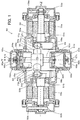
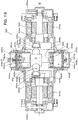
- Fig. 1 is a configuration diagram illustrating the schematic configuration of a positive displacement machine 20 according to one embodiment of the disclosure.
- the positive displacement machine 20 of the embodiment is configured as a compressor to increase the pressure of a gas serving as a working fluid.
- the positive displacement machine 20 includes a guide cylindrical member 30 in a cylindrical shape having a center axis extended in a vertical direction (Y-axis direction) in the drawing, a reciprocating member 40 configured such that a pair of pistons 42a and 42b are guided by this guide cylindrical member 30 to be reciprocated in the vertical direction (Y-axis direction) in the drawing while swinging around a center axis (Y axis) of the guide cylindrical member 30, a pair of shaft members 50a and 50b arranged to be rotated about a rotation axis that is a straight line (Z axis) perpendicular to the center axis of the guide cylindrical member 30 at the center of the guide cylindrical member 30, a pair of working chambers 62a and 62b configured to change their volumes by the reciproc
- a pair of first arm portions 44a and 44b are mounted in the center of the reciprocating member 40 to be perpendicular to the center axis (Y axis) of the guide cylindrical member 30 and to be symmetrical about the center axis.
- Outer peripheral spherical portions 45a and 45b having centers of sphere P1a and P1b on respective arm axes are formed at or attached and fixed to respective ends of the first arm portions 44a and 44b.
- Fluid flow paths 63a and 63b are formed in the pistons 42a and 42b to supply the working fluid to the working chambers 62a and 62b.
- Suction valves 64a and 64b are mounted to the fluid flow paths 63a and 63b and are opened when the pressure in the working chambers 62a and 62b becomes lower than the pressure in a working fluid space 60 between the pistons 42a and 42b.
- Discharge valves 67a and 67b are mounted to the partition walls 65a and 65b placed between the working chambers 62a and 62b and the high pressure chambers 66a and 66b and are opened when the pressure in the working chambers 62a and 62b becomes higher than the pressure in the high pressure chambers 66a and 66b.
- Outlet pipes 68a and 68b are mounted to the high pressure chambers 66a and 66b. Additionally, a non-illustrated inlet pipe arranged to communicate with the working fluid space 60 is mounted to the casing 22. Accordingly the working fluid flows from the inlet pipe into the working fluid space 60, is supplied to the working chambers 62a and 62b via the fluid flow paths 63a and 63b and the suction valves 64a and 64b by the reciprocating motion of the pistons 42a and 42b, subsequently flows into the high pressure chambers 66a an 66b via the discharge valves 67a and 67b and flows out from the outlet pipes 68a and 68b.
- the shaft members 50a and 50b are supported to be rotatable by means of ball bearings 51a, 51b, 52a and 52b.
- a pair of second arm portions 54a and 54b are mounted at positions deviated from their rotation axes on respective one ends (reciprocating member 40-side ends) to support the first arm portions 44a and 44b of the reciprocating member 40.
- the second arm portions 54a and 54b are provided as inner peripheral cylindrical members having a center axis that is an axis parallel to the rotation axis of the shaft members 50a and 50b and are configured such that the outer peripheral spherical portions 45a and 45b of the first arm portions 44a and 44b are placed in their inner peripheral cylinders in a slidable manner.
- Figs. 2(a) to 2(e) are diagrams illustrating the state of the reciprocating member 40 during reciprocating motion with swing motion.
- Figs. 3 (a) to 3 (e) are diagrams illustrating the reciprocating member 40 during reciprocating motion with swing motion viewed downward in Fig. 1 .
- Figs. 3 (a) to 3 (e) illustrate changes in the state of the reciprocating member 40 by every 90 degree rotation of the shaft members 50a and 50b from the location at the center of the reciprocating motion.
- the reciprocating member 40 is reciprocated with an amplitude 2 ⁇ between a top dead center shown in Fig. 2(b) and a bottom dead center shown in Fig. 2(d) , while swinging with a counterclockwise swing piece amplitude angle ⁇ max shown in Figs. 3 (a) and 3(e) and a clockwise swing piece amplitude angle ⁇ max shown in Fig. 3 (c) .
- Figs. 3 (a) and 3(e) a clockwise swing piece amplitude angle ⁇ max shown in Fig. 3 (c) .
- the outer peripheral spherical portion 45a on the front side is revolved counterclockwise, while the outer peripheral spherical portion 45b on the rear side is revolved clockwise.
- the shaft member 50a is rotated counterclockwise, while the shaft member 50b is rotated clockwise.
- Figs. 4(a) and 4(b) are enlarged diagrams illustrating the first arm portion 44a and the second arm portion 54a of the reciprocating member 40 during reciprocating motion with swing motion.
- Fig. 4 (a) illustrates the state at the top dead center (swing angle of 0 degree) viewed from the same direction as Fig. 1 .
- Fig. 4(b) illustrates the state at the maximum swing angle (swing piece amplitude angle ⁇ max) viewed downward in Fig. 1 .
- the outer peripheral spherical portion 45a mounted to the first arm portion 44a is slid relative to the inner peripheral cylindrical surface of the second arm portion 55a by the swing motion to be moved by ⁇ L in the axial direction of the second arm portion 54a.
- the center of sphere P1a of the outer peripheral spherical portion 45a is constrained on the axis of the second arm portion 54a.
- the centers of sphere P1a and P1b are also called "specific points P1a and P1b".
- a pair of main weight balances 58a and 58b are mounted on respective one ends of the shaft members 50a and 50b such that the direction of their centrifugal force is opposite to the direction of the second arm portions 54a and 54b.
- a pair of sub-weight balances 59a and 59b are mounted on respective other ends of the shaft members 50a and 50b (opposite ends opposite to the reciprocating member 40-sides) such that the direction of their centrifugal force is opposite to the direction of the main weight balances 58a and 58b.
- the positive displacement machine 20 of the embodiment having the above configuration causes no vibration force other than the torque about the Y axis to be generated among the inertial forces in the directions of three axes (X axis, Y axis and Z axis) in a rectangular coordinate system and the torques about the three axes by the inertial forces.
- the following describes comparison between the positive displacement machine 20 of the embodiment and the prior art positive displacement machine 920 with regard to the torque about the Y axis.
- Fig. 5 is a diagram illustrating part of the reciprocating member 40 and the shaft members 50a and 50b during swing motion viewed downward in Fig. 1 .
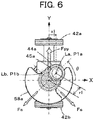
- Fig. 6 is a diagram illustrating part of the reciprocating member 40 and the shaft members 50a and 50b during swing motion viewed leftward in Fig. 1 .
- Ip1 denotes a moment of inertia about the Y axis of the reciprocating member 40 and ⁇ p1 denotes an angular acceleration by the swing motion
- Equation (2) also indicates an X coordinate of the specific point P1a.
- a swing angle ⁇ p1 is expressed by Equation (3) given below.
- a swing piece amplitude angle ⁇ max1 in the swing motion of the reciprocating member 40 is expressed by Equation (4) given below using Equation (3).
- Equation (5) is obtained by substituting Equation (4) into Equation (3): [Math.
- an X-axis direction component Fsx of an overall centrifugal force Fs of the shaft members 50a and 50b is cancelled out by the shaft members 50a and 50b that are rotated in the reverse directions. Due to the difference of the working position in the Z-axis direction, however, the centrifugal forces serve as a couple of forces, so that a torque about the Y axis remains.
- the main weight balances 58a and 58b are mounted to the shaft members 50a and 50b such that the direction of their centrifugal force is opposite to the direction of the second arm portions 54a and 54b.
- the sub-weight balances 59a and 59b are mounted to the shaft members 50a and 50b such that the direction of their centrifugal force is identical with the direction of the second arm portions 54a and 54b. Among the centrifugal forces generated by the respective portions, the centrifugal force by the main weight balances 58a and 58b is dominant. The direction of the centrifugal force Fs is accordingly equal to the direction of the centrifugal force of the main weight balances 58a and 58b.
- ⁇ denotes a rotational angular velocity of the shaft members 50a and 50b
- mr denotes a constant
- the X-axis direction component Fsx of the centrifugal force Fs is expressed by Equation (6) given below.
- the X-axis direction component Fsx acts at the positions of Z-axis coordinates lmr and -lmr, so that the torque about the Y axis is expressed by Equation (7) given below.
- the two constants lmr and mr may be regulated independently of each other to any arbitrary values by adjusting two variables indicating the sizes of the main weight balances 58a and 58b and the sub-weight balances 59a and 59b.
- the rotational angular velocity ⁇ is also given as a constant.
- the torque Ns is expressed by a cosine function of the rotational angle ⁇ of the shaft members 50a and 50b and has only a rotational primary component.
- Equation (9) is obtained by substituting Equation (8) into Equation (1).
- Equations (10) and (11) are obtained by substituting Equation (5) into Equation (9) with regard to the swing piece amplitude angle ⁇ max1 equal to 15 degrees (0.263rad) and 25 degrees (0.436 rad) and performing Fourier series expansion of a dimensionless swing torque Np1* that is obtained by division by Ip1 ⁇ 2 and normalization. Fourth and subsequent terms on the right sides of Equations (10) and (11) have negligibly small coefficients and are thus omitted. [Math.
- the rotational primary component of the shaft members 50a and 50b corresponding to the first term is dominant in the torque Np1 about the Y axis by the inertial force generated by the swing motion of the reciprocating member 40.
- the rotational primary component is, however, cancelled out and eliminated by a torque about the Y axis by the centrifugal force of a shaft member by adjusting the constants lmr and mr in Equations (6) and (7). Accordingly the higher-order terms that are the second and subsequent terms on the right sides of Equations (10) and (11) remain as components of vibrating the periphery.
- Equation (13) an X-axis coordinate x2 of the center of sphere P2a is expressed by Equation (13) given below.
- 12 shown in Fig. 20
- Equation (17) A swing piece amplitude angle ⁇ max2 in the swing motion of the reciprocating member 940 is expressed by Equation (17) based on Equation (14).
- Equation (18) is obtained by substituting Equation (17) into Equation (14).
- Equations (19) and (20) are obtained by substituting Equation (18) into Equation (16) with regard to the swing piece amplitude angle ⁇ max2 equal to 15 degrees (0.263rad) and 25 degrees (0.436 rad) and performing Fourier series expansion of a dimensionless swing torque Np2* that is obtained by division by Ip ⁇ 2 and normalization.
- Fourth and subsequent terms on the right sides of Equations (19) and (20) have negligibly small coefficients and are thus omitted. [Math.
- the rotational primary component of the shaft member 950a and 950b corresponding to the first term is dominant in the torque Np2 about the Y axis by the inertial force generated by the swing motion of the reciprocating member 940.
- the rotational primary component is, however, cancelled out and eliminated by a torque about the Y axis by the centrifugal force of a shaft member by adjusting the constants lmr and mr in Equations (6) and (7). Accordingly the higher-order terms that are the second and subsequent terms on the right sides of Equations (19) and (20) remain as components of vibrating the periphery.
- the positive displacement machine 20 of the embodiment has the smaller coefficients, irrespective of the swing piece amplitude angle ⁇ max. Accordingly the positive placement machine 20 of the embodiment has the smaller vibration torque of vibrating the periphery, compared with the prior art positive displacement machine 920.
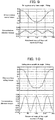
- Figs. 7 and 8 are graphs showing relations of a dimensionless swing torque and a dimensionless vibration torque to the rotational angle ⁇ of the shaft members 50a and 50b at the swing piece amplitude angle equal to 15 degrees and 25 degrees in the positive displacement machine 20 of the embodiment.
- Figs. 9 and 10 are graphs showing relations of a dimensionless swing torque and a dimensionless vibration torque to the rotational angle ⁇ of the shaft members 950a and 950b at the swing piece amplitude angle equal to 15 degrees and 25 degrees in the prior art positive displacement machine 920.
- a broken-line curve of the dimensionless swing torque shows a cosine curve of the rotational primary component.
- the dimensionless vibration torque is accordingly provided as a difference between the swing torque and the rotational primary component.
- Comparison between Fig. 7 and Fig. 9 and comparison between Fig. 8 and 10 show that the the positive displacement machine 20 of the embodiment has the smaller vibration torque than the prior art positive displacement machine 920.
- the second arm portions 54a and 54b formed as inner peripheral cylindrical surfaces about the center axis that is the axis parallel to the rotation axis of the shaft members 50a and 50b are configured to support the first arm portions 44a and 44b such that the centers of sphere P1a and P1b of the outer peripheral spherical portions 45a and 45b mounted to the first arm portions 44a and 44b are constrained on the center axis of the second arm portions 54a and 54b.
- This configuration reduces the vibration torque of vibrating the periphery, compared with the prior art positive displacement machine 920.
- the outer peripheral spherical portions 45a and 45b are formed at or attached and fixed to the first arm portions 44a and 44b.
- an outer peripheral spherical portion 145a may be held by a first arm portion 144a to be rotatable about an arm axis.
- Fig. 11 (a) illustrates the state at the top dead center (swing angle of 0 degree) viewed from the same direction as Fig. 1 .
- Fig. 11 (b) illustrates the state at the maximum swing angle (swing piece amplitude angle ⁇ max) viewed downward in Fig. 1 .
- an attachment portion of the first arm portion 144a to which the outer peripheral spherical portion 145a is attached may be formed in a cylindrical shape about an arm axis as the center axis, and an inner peripheral surface of the outer peripheral spherical portion 145a may be formed in a cylindrical shape.
- a roller 146a may be placed between the outer peripheral spherical portion 145a and the first arm portion 144a to make the outer peripheral spherical portion 145a rotatable about the arm axis.
- Thrust washers 147a and 148a may be mounted on respective end faces in the direction of the arm axis of the outer peripheral spherical portion 145a, so as to restrict the motion of the outer peripheral spherical portion 145a in the direction of the arm axis.
- This configuration provides a rolling pair at the line contact between the outer peripheral spherical portion 145a and an inner peripheral surface of a second arm portion 54a and thereby improves the durability and reduces the mechanical friction loss.
- the outer peripheral spherical portions 45a and 45b of the first arm portions 44a and 44b are held in a slidable manner by the second arm portions 54a and 54b formed as the inner peripheral cylindrical surfaces.
- an outer peripheral spherical portion 45a of a first arm portion 44a may be supported by a second arm portion 154a via an inner peripheral spherical portion 155a.
- Fig. 12 (a) illustrates the state at the top dead center (swing angle of 0 degree) viewed from the same direction as Fig. 1 .
- FIG. 12(b) illustrates the state at the maximum swing angle (swing piece amplitude angle ⁇ max) viewed downward in Fig. 1 .
- an outer peripheral cylindrical surface of the inner peripheral spherical portion 155a may be held by an inner peripheral cylindrical surface of the second arm portion 154a to be slidable in the circumferential direction and in the direction of the arm axis, and the outer peripheral spherical portion 45a of the first arm portion 44a may be held as a spherical pair by the inner peripheral spherical portion 155a.
- Figs. 13(a) and 13(b) illustrate a third modification shown in Figs. 13(a) and 13(b).
- Fig. 13(a) illustrates the state at the top dead center (swing angle of 0 degree) viewed from the same direction as Fig. 1 .
- Fig. 13 (b) illustrates the state at the maximum swing angle (swing piece amplitude angle ⁇ max) viewed downward in Fig. 1 .
- the configuration of the third modification provided as the combination of the first modification and the second modification further reduces the mechanical friction loss and further improves the durability in the support structure.
- the first arm portion 44a-side end face or the first arm portion 144a-side end face of the inner peripheral spherical portion 155a is formed to be parallel to a plane perpendicular to the rotation axis of the shaft member 50a.
- an end face of an inner peripheral spherical portion 255a may be formed as an inclined surface that is inclined to the rotation axis of a shaft member 50a such that an inner circumferential side of the inner peripheral spherical portion 255a about the rotation axis of the shaft member 50a is farther away from a first arm portion 144a than its outer circumferential side.
- Fig. 14(a) illustrates the state at the top dead center (swing angle of 0 degree) viewed from the same direction as Fig. 1 .
- Fig. 14 (b) illustrates the state at the maximum swing angle (swing piece amplitude angle ⁇ max) viewed downward in Fig. 1 .
- the inner peripheral spherical portion 255a may be mounted to an inner peripheral cylindrical surface of a second arm portion 254a such as to be movable in the axial direction relative to the inner peripheral cylindrical surface but to be not rotatable about the center axis.
- Such mounting may be achieved by, for example, spline fitting in which the inner peripheral cylindrical surface and the inner peripheral spherical portion 255a are slidable in the axial direction.
- the configuration that the end face of the inner peripheral spherical portion 255a is formed as the inclined surface suppresses the first arm portion 144a from coming into contact with and interfering with the inner circumferential side of the inner peripheral spherical portion 255a about the rotation axis of the shaft member 50a at the maximum swing angle (swing piece amplitude angle) and allows for a greater maximum swing angle of the reciprocating member 40.
- the end face of the inner peripheral spherical portion 255a is formed as the inclined surface.
- a first arm portion 144a-side end face of the inner peripheral cylindrical surface of the second arm portion 254a is formed as an inclined surface like the end face of the inner peripheral spherical portion 255a.
- the first arm portion 144a-side end face of the inner peripheral cylindrical surface of the second arm portion 254a may be formed to be parallel to the plane perpendicular to the rotation axis of the shaft member 50a.
- the outer peripheral spherical portions 45a and 45b are formed at or attached and fixed to the first arm portions 44a and 44b.
- an outer peripheral spherical portion 355a may be mounted to a second arm portion 354a.
- Fig. 15(a) illustrates the state at the top dead center (swing angle of 0 degree) viewed from the same direction as Fig. 1 .
- Fig. 15 (b) illustrates the state at the maximum swing angle (swing piece amplitude angle ⁇ max) viewed downward in Fig. 1 .
- the second arm portion 354a may be provided as an outer peripheral cylindrical surface, and an inner peripheral cylindrical surface of the outer peripheral spherical portion 355a may be held by the second arm portion 354a such as to be slidable in the direction of the arm axis of the second arm portion 354a.
- An inner peripheral spherical portion 346a configured to rotatably hold the outer peripheral spherical portion 355a may be mounted to the second arm portion 354a by a mounting member 345a such as to be not movable in the direction of the arm axis of a first arm portion 344a.
- an inner peripheral spherical portion 446a of a first arm portion 444a may be formed to have an outer peripheral cylindrical surface.
- a roller 447a may be placed between the outer peripheral surface of the inner peripheral spherical portion 446a and an inner peripheral surface of a mounting member 445a such that the inner peripheral spherical portion 446a is rotatable about the arm axis of the first arm portion 444a.
- Fig. 16(a) illustrates the state at the top dead center (swing angle of 0 degree) viewed from the same direction as Fig. 1 .
- Fig. 16 (b) illustrates the state at the maximum swing angle (swing piece amplitude angle ⁇ max) viewed downward in Fig. 1 .
- the outer peripheral spherical portions 45a and 45b are formed at or attached and fixed to the first arm portions 44a and 44b and are held to be slidable by the inner peripheral cylindrical surfaces of the second arm portions 54a and 54b.
- outer peripheral spherical portions may be omitted.
- Fig. 17 (a) illustrates the state at the top dead center (swing angle of 0 degree) viewed from the same direction as Fig. 1 .
- Fig. 17 (b) illustrates the state at the maximum swing angle (swing piece amplitude angle ⁇ max) viewed downward in Fig. 1 .
- Fig. 17 (a) illustrates the state at the top dead center (swing angle of 0 degree) viewed from the same direction as Fig. 1 .
- Fig. 17 (b) illustrates the state at the maximum swing angle (swing piece amplitude angle ⁇ max) viewed downward in Fig. 1 .
- Fig. 17 (a) illustrates the state at the top dead center (swing
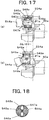
- a second arm portion 554a may be formed as an inner peripheral cylindrical surface.
- An approximately barrel-shaped hinge portion 545a having two planes perpendicular to the direction of the reciprocating motion of the reciprocating member 40 (vertical direction in Fig. 1 and vertical direction in Fig. 17(a) ) may be formed at or attached and fixed to a first arm portion 544a.
- the first arm portion 544a may include a cylindrical member 548a in a cylindrical shape arranged to be slidable relative to the inner peripheral cylindrical surface of the second arm portion 554a, and a pair of sliding members 546a integrated with the cylindrical member 548a and arranged to come into contact with the two planes of the hinge portion 545a in a slidable manner.
- the pair of sliding members 546a may be swung relative to the hinge portion 545a about a pin 547a arranged to pass through the center axis of the hinge portion 545 and may be supported at the respective ends by a pair of retaining rings 549a such as to be not movable relative to the cylindrical member 548a in the direction of the center axis of the cylindrical member 548a.
- the hinge portion 545a formed at or attached and fixed to the first arm portion 544a may be swung relative to the cylindrical member 548a about the pin 547a as the swing axis.
- the cylindrical member 485a may be configured to be slidable about the arm axis relative to the inner peripheral cylindrical surface of the second arm portion 554a.
- a specific point P1a at the center of the hinge portion 545a (center of the pin 547a) is accordingly constrained in a movable manner on the axis parallel to the rotation axis of the shaft member 50a (on the center axis of the second arm portion 554a). This configuration causes the first arm portion 544a to be rotatable and swingable relative to the second arm portion 554a.
- this configuration enables the first arm portion 544a to be revolved by the reciprocating motion with the swing motion of the reciprocating member 40, while being held by the second arm portion 554a.
- the seventh modification accordingly provides the similar advantageous effects to those of the positive displacement machine 20 of the embodiment.
- any support structure may be employed to support the first arm portion by the second arm portion as long as the support structure causes a predetermined specific point of the first arm portion to be constrained in a rotatable manner on an axis parallel to the rotation axis of the shaft member.
- any of the positive displacement machine 20 of the embodiment and its modifications is provided as a machine (compressor) of producing changes in the volumes of the working chambers 62a and 62b by the reciprocating motion and the swing motion of the reciprocating member 40, which is caused by driving and rotating the shaft members 50a and 50b in the reverse directions by the pair of motors 70a and 70b mounted to the pair of shaft members 50a and 50b.
- Any of the positive displacement machine 20 of the embodiment and its modifications may, however, be provided as a machine (engine) of producing the rotational driving force in the pair of shaft members 50a and 50b by the reciprocating motion and the swing motion of the reciprocating member 40, which is caused by supplying a pressure fluid to the working chambers 62a and 62b.
- the positive displacement machine 20 of the embodiment and its modifications respectively include the pair of pistons 42a and 42b and the pair of working chambers 62a and 62b, but may include a single piston and a single working chamber.
- the present disclosure is applicable in, for example, manufacturing industries of positive displacement machine.
Landscapes
- Engineering & Computer Science (AREA)
- Mechanical Engineering (AREA)
- General Engineering & Computer Science (AREA)
- Chemical & Material Sciences (AREA)
- Combustion & Propulsion (AREA)
- Compressors, Vaccum Pumps And Other Relevant Systems (AREA)
- Compressor (AREA)
Abstract
Description
- The present disclosure relates to a positive displacement machine and more specifically a low vibration-type positive displacement machine configured such that pistons are reciprocated while swinging.
- A proposed configuration of this type of positive displacement machine includes a reciprocating member including two pistons guided by a guide cylindrical member and a pair of first arm portions arranged symmetrically in a direction perpendicular to a center axis of the guide cylindrical member from the middle of the two pistons; a pair of shaft members arranged symmetrically to be perpendicular to the center axis of the guide cylindrical member; a pair of second arm portions mounted to the shaft members at positions deviated from rotation axes of the respective shaft members to hold the respective first arm portions; and a pair of working chambers configured to have a change in volume by the reciprocating motion of the two pistons, where in the reciprocating member is configured to be reciprocated with a swing motion (as shown in, for example, Patent Literature 1).
Fig. 19 is a configuration diagram illustrating the schematic configuration of a prior artpositive displacement machine 920.Fig. 20 is a diagram illustrating part of a reciprocatingmember 940 andshaft members Fig. 19 .Fig. 21 is a diagram illustrating part of the reciprocatingmember 940 and theshaft members Fig. 19 . For the purpose of comparison with apositive displacement machine 20 according to one embodiment of the disclosure described later, the prior artpositive displacement machine 920 has a similar configuration to that of thepositive displacement machine 20 of the embodiment, except a support structure to supportfirst arm portions second arm portions - As shown in
Fig. 19 , the prior artpositive displacement machine 920 includes a guidecylindrical member 930 in a cylindrical shape having a center axis extended in a vertical direction (Y-axis direction) in the drawing, a reciprocatingmember 940 configured such that a pair ofpistons cylindrical member 930 to be reciprocated in the vertical direction (Y-axis direction) in the drawing while swinging around a center axis (Y axis) of the guidecylindrical member 930, a pair ofshaft members cylindrical member 930 at the center of the guidecylindrical member 930, a pair ofworking chambers pistons high pressure chambers working chambers discharge valves motors shaft members first arm portions member 940 to be perpendicular to the center axis of the guidecylindrical member 930 and to be symmetrical about the center axis. A pair ofsecond arm portions first arm portions shaft members main weight balances shaft members second arm positions sub-weight balances shaft members main weight balances - As shown in
Fig. 20 , outer peripheralspherical portions first arm portions second arm portions spherical portions first arm portions shaft members second arm portions spherical portions first arm portions member 940. -
Fluid flow paths pistons chambers Suction valves fluid flow paths chambers fluid space 960 between thepistons Discharge valves partition walls chambers high pressure chambers working chambers high pressure chambers Outlet pipes high pressure chambers fluid space 960 is mounted to acasing 922. Accordingly the working fluid flows from the inlet pipe into theworking fluid space 960, is supplied to theworking chambers fluid flow paths suction valves pistons high pressure chambers 966a an 966b via thedischarge valves outlet pipes - In this prior art
positive displacement machine 920, an inertial force Fpy is generated in a direction of the center axis (Y-axis direction) of the reciprocatingmember 940, accompanied with reciprocating motion of the reciprocatingmember 940. This inertial force Fpy may be completely eliminated by a Y-axis direction component Fsy of an overall centrifugal force Fs by thesecond arm portions main balance weights sub-weight balances shaft members shaft members shaft members positive displacement machine 920, as described above, the motions of the respective component members and the forces applied between the respective component members are symmetrical with respect to the center axis of the reciprocatingmember 940. This arrangement causes no inertial force in the direction of the rotation axis (Z-axis direction) of theshaft members positive displacement machine 920 accordingly causes no vibration force other than the torque about the Y axis to be generated among the inertial forces in the directions of three axes (X axis, Y axis and Z axis) in a rectangular coordinate system and the torques about the three axes by the inertial forces. The torque about the Y axis may be mostly eliminated by adjusting the size of themain balance weights sub-balance weights positive displacement machine 920 has an extremely small vibration force to the periphery. - PTL 1:
JP H09-92275A Figs. 7 to 11 ) - In the prior art
positive displacement machine 920, the arm length of thefirst arm portions first arm portions main weight balances sub-weight balances member 940. In the prior artpositive displacement machine 920, the diameter of thepistons working chambers member 940 and increases the maximum swing angle (swing piece amplitude angle) of the reciprocatingmember 940. An increase in the maximum swing angle (swing piece amplitude angle) increases the torque about the Y axis that is less likely to be completely eliminated and thereby vibrates the periphery. - A main object of the disclosure is to provide a lower vibration-type positive displacement machine.
- In order to achieve the main object described above, the positive displacement machine of the disclosure may be implemented by various aspects described below.
- The present disclosure is directed to a positive displacement machine. The positive displacement machine includes
a guide cylindrical member formed in a cylindrical shape,
a reciprocating member including a piston portion configured to be guided by an inner peripheral surface of the guide cylindrical member to be reciprocated in a direction of a center axis of the guide cylindrical member while swinging about the center axis, and a pair of first arm portions mounted to the piston portion to be perpendicular to the center axis of the guide cylindrical member and to be symmetrical with respect to the center axis,
a pair of shaft members arranged to be perpendicular to the center axis of the guide cylindrical member and to be symmetrical with respect to the center axis,
a pair of second arm portions mounted to the pair of shaft members, such as to respectively support the pair of first arm portions at positions deviated from rotation axes of the pair of shaft members,
and a working chamber configured to have a change in volume accompanied with a reciprocating motion of the piston portion. The second arm portion supports the first arm portion such that a predetermined specific point in the first arm portion is constrained in a movable manner on an axis parallel to the rotation axis of the shaft member. - In the positive displacement machine of this aspect, the first arm portion is supported by the second arm portion such that the predetermined specific point in the first arm portion is constrained in a movable manner on the axis parallel to the rotation axis of the shaft member. This provides the lower vibration-type positive displacement machine. The expression of "constrained in a movable manner on the axis" means that only the motion on the axis is allowed. The positive displacement machine of this aspect may be provided as a machine (for example, an engine) of producing a rotational driving force in the pair of shaft members by the reciprocating motion and the swing motion of the reciprocating member, which is caused by supplying a pressure fluid to the working chamber. The positive displacement machine of this aspect may also be provided as a machine (for example, a compressor) of producing a change in the volume of the working chamber by the reciprocating motion and the swing motion of the reciprocating member, which is caused by supplying a rotational driving force to the pair of shaft members. In these cases, the piston portion may include two pistons arranged symmetrically across the pair of first arm portions, and two working chambers may be provided corresponding to the two pistons.
- In such a positive displacement machine of the present disclosure, the first arm portion may include an outer peripheral spherical portion having a center of sphere as the specific point and the second arm portion may include an inner peripheral cylindrical portion that is arranged on the axis parallel to the rotation axis of the shaft member and is configured to hold the outer peripheral spherical portion in a slidable manner.
- In the positive displacement machine of the present disclosure, the first arm portion may include an outer peripheral spherical portion having a center of sphere as the specific point, and the second arm portion may include an inner peripheral spherical portion that is configured to hold the outer peripheral spherical portion and to move on the axis parallel to the rotation axis of the shaft member. This configuration causes the outer peripheral spherical portion to be held by the inner peripheral spherical portion and accordingly allows for transmission of forces between the first arm portion and the second arm portion by surface contact. In the positive displacement machine of the present disclosure of this embodiment, the inner peripheral spherical portion may be formed to have an outer peripheral cylindrical surface, and the second arm portion may include an inner peripheral cylindrical portion that is configured to hold the inner peripheral spherical portion such as to be movable on the axis parallel to the rotation axis of the shaft member. This configuration enables the outer peripheral spherical portion to be smoothly rotated about the axis parallel to the rotation axis of the shaft member, accompanied with the reciprocating motion and the swing motion of the reciprocating member and thereby reduces the mechanical friction loss.
- In the positive displacement machine of the present disclosure of the embodiment in which the inner peripheral cylindrical portion of the second arm portion holds the inner peripheral spherical portion, the inner peripheral spherical portion may be formed such that an inner circumferential side of the shaft member about the rotation axis is farther away from the first arm portion than an outer circumferential side, and the inner peripheral cylindrical portion may be configured to hold the inner peripheral spherical portion such as to be not rotatable about the axis parallel to the rotation axis of the shaft member. This configuration suppresses the first arm portion from coming into contact with and interfering with the inner circumferential side of the inner peripheral spherical portion of the second arm portion about the rotation axis of the shaft at the maximum swing angle (swing piece amplitude angle) of the reciprocating member and thereby further increases the maximum swing angle (swing piece amplitude angle) of the reciprocating member. In this aspect, an end face of the inner peripheral spherical portion may be formed as an inclined surface that is inclined to the rotation axis of the shaft member.
- In the positive displacement machine of the present disclosure of the embodiment in which the first arm portion includes an outer peripheral spherical portion, the outer peripheral spherical portion may be supported such as to be rotatable about the center axis of the first arm portion and to be not movable in a direction of the center axis. This configuration enables the outer peripheral spherical portion to be smoothly rotated about the center axis of the first arm portion, accompanied with the reciprocating motion and the swing motion of the reciprocating member and thereby reduces the mechanical friction loss.
- In the positive displacement machine of the present disclosure, the first arm portion may include an inner peripheral spherical portion having a center of sphere as the specific point, and the second arm portion may include an outer peripheral spherical portion that is held by the inner peripheral spherical portion and is configured to be movable on the axis parallel to the rotation axis of the shaft member. In this case, the inner peripheral spherical portion may be supported to be rotatable about the center axis of the first arm portion and to be not movable in a direction of the center axis. This configuration enables the inner peripheral spherical portion to be smoothly rotated about the center axis of the first arm portion, accompanied with the reciprocating motion and the swing motion of the reciprocating member and thereby reduces the mechanical friction loss.
- Further, in the positive displacement machine of the present disclosure, the second arm portion may be formed as an inner peripheral cylindrical surface, and the first arm portion may include an approximately barrel-shaped hinge portion having two planes that are perpendicular to a direction of reciprocating motion of the reciprocating member, and a sliding portion configured to come into contact with the two planes of the hinge portion in a slidable manner and come into contact with the inner peripheral cylindrical surface of the second arm portion in a slidable manner and integrated with the hinge portion by a pin provided at a center axis of the hinge portion.
-
-
Fig. 1 is a configuration diagram illustrating the schematic configuration of apositive displacement machine 20 according to one embodiment of the disclosure; -
Figs. 2(a) to 2(e) are diagrams illustrating the state of a reciprocatingmember 40 during reciprocating motion with swing motion; -
Figs. 3 (a) to 3(e) are diagrams illustrating the reciprocatingmember 40 during reciprocating motion with swing motion viewed downward inFig. 1 ; -
Figs. 4 (a) and 4(b) are enlarged diagrams illustrating afirst arm portion 44a and asecond arm portion 54a of the reciprocatingmember 40 during reciprocating motion with swing motion; -
Fig. 5 is a diagram illustrating part of the reciprocatingmember 40 andshaft members Fig. 1 ; -
Fig. 6 is a diagram illustrating part of the reciprocatingmember 40 and theshaft members Fig. 1 ; -
Fig. 7 is graphs showing relations of a dimensionless swing torque and a dimensionless vibration torque to a rotational angle θ of theshaft members positive displacement machine 20 of the embodiment; -
Fig. 8 is graphs showing relations of the dimensionless swing torque and the dimensionless vibration torque to the rotational angle θ of theshaft members positive displacement machine 20 of the embodiment; -
Fig. 9 is graphs showing relations of the dimensionless swing torque and the dimensionless vibration torque to a rotational angle θ ofshaft members positive displacement machine 920; -
Fig. 10 is graphs showing relations of the dimensionless swing torque and the dimensionless vibration torque to the rotational angle θ of theshaft members positive displacement machine 920; -
Figs. 11(a) and 11(b) are enlarged diagrams illustrating a support structure of afirst arm portion 144a by asecond arm portion 54a in a positive displacement machine of a first modification; -
Figs. 12(a) and 12(b) are enlarged diagrams illustrating a support structure of afirst arm portion 44a by asecond arm portion 154a in a positive displacement machine of a second modification; -
Figs. 13(a) and 13(b) are enlarged diagrams illustrating a support structure of afirst arm portion 144a by asecond arm portion 154a in a positive displacement machine of a third modification; -
Figs. 14(a) and 14(b) are enlarged diagrams illustrating a support structure of afirst arm portion 144a by asecond arm portion 254a in a positive displacement machine of a fourth modification; -
Figs. 15(a) and 15(b) are enlarged diagrams illustrating a support structure of afirst arm portion 344a by asecond arm portion 354a in a positive displacement machine of a fifth modification; -
Figs. 16(a) and 16(b) are enlarged diagrams illustrating a support structure of afirst arm portion 444a by asecond arm portion 354a in a positive displacement machine of a sixth modification; -
Figs. 17(a) and 17(b) are enlarged diagrams illustrating a support structure of afirst arm portion 544a by asecond arm portion 554a in a positive displacement machine of a seventh modification; -
Fig. 18 is a sectional view illustrating an A-A section ofFig. 17 ; -
Fig. 19 is a configuration diagram illustrating the schematic configuration of the prior artpositive displacement machine 920; -
Fig. 20 is a diagram illustrating a configuration of supportingfirst arm portions second arm portions -
Fig. 21 is a diagram illustrating part of a reciprocatingmember 940 andshaft members Fig. 19 . - The following describes some aspects of the disclosure with reference to an embodiment.
-
Fig. 1 is a configuration diagram illustrating the schematic configuration of apositive displacement machine 20 according to one embodiment of the disclosure. Thepositive displacement machine 20 of the embodiment is configured as a compressor to increase the pressure of a gas serving as a working fluid. As illustrated, thepositive displacement machine 20 includes a guidecylindrical member 30 in a cylindrical shape having a center axis extended in a vertical direction (Y-axis direction) in the drawing, a reciprocatingmember 40 configured such that a pair ofpistons cylindrical member 30 to be reciprocated in the vertical direction (Y-axis direction) in the drawing while swinging around a center axis (Y axis) of the guidecylindrical member 30, a pair ofshaft members cylindrical member 30 at the center of the guidecylindrical member 30, a pair of workingchambers 62a and 62b configured to change their volumes by the reciprocating motion of thepistons high pressure chambers chambers 62a and 62b acrosspartition walls motors shaft members casing 22 configured to place the foregoing components. - A pair of
first arm portions member 40 to be perpendicular to the center axis (Y axis) of the guidecylindrical member 30 and to be symmetrical about the center axis. Outer peripheralspherical portions first arm portions -
Fluid flow paths pistons chambers 62a and 62b.Suction valves fluid flow paths chambers 62a and 62b becomes lower than the pressure in a workingfluid space 60 between thepistons Discharge valves partition walls chambers 62a and 62b and thehigh pressure chambers chambers 62a and 62b becomes higher than the pressure in thehigh pressure chambers Outlet pipes high pressure chambers fluid space 60 is mounted to thecasing 22. Accordingly the working fluid flows from the inlet pipe into the workingfluid space 60, is supplied to the workingchambers 62a and 62b via thefluid flow paths suction valves pistons high pressure chambers 66a an 66b via thedischarge valves outlet pipes - The
shaft members ball bearings second arm portions first arm portions member 40. Thesecond arm portions shaft members spherical portions first arm portions shaft members second arm portions spherical portions first arm portions shaft members member 40 is reciprocated with swinging.Figs. 2(a) to 2(e) are diagrams illustrating the state of the reciprocatingmember 40 during reciprocating motion with swing motion.Figs. 3 (a) to 3 (e) are diagrams illustrating the reciprocatingmember 40 during reciprocating motion with swing motion viewed downward inFig. 1 .Figs. 2 (a) to 2 (e) and Figs. 3 (a) to 3 (e) illustrate changes in the state of the reciprocatingmember 40 by every 90 degree rotation of theshaft members member 40 is reciprocated with an amplitude 2ε between a top dead center shown inFig. 2(b) and a bottom dead center shown inFig. 2(d) , while swinging with a counterclockwise swing piece amplitude angle θmax shown inFigs. 3 (a) and 3(e) and a clockwise swing piece amplitude angle θmax shown inFig. 3 (c) . InFigs. 2 (a) to 2 (e) , the outer peripheralspherical portion 45a on the front side is revolved counterclockwise, while the outer peripheralspherical portion 45b on the rear side is revolved clockwise. As illustrated, accompanied with this revolution, theshaft member 50a is rotated counterclockwise, while theshaft member 50b is rotated clockwise. -
Figs. 4(a) and 4(b) are enlarged diagrams illustrating thefirst arm portion 44a and thesecond arm portion 54a of the reciprocatingmember 40 during reciprocating motion with swing motion.Fig. 4 (a) illustrates the state at the top dead center (swing angle of 0 degree) viewed from the same direction asFig. 1 .Fig. 4(b) illustrates the state at the maximum swing angle (swing piece amplitude angle θmax) viewed downward inFig. 1 . As illustrated, the outer peripheralspherical portion 45a mounted to thefirst arm portion 44a is slid relative to the inner peripheral cylindrical surface of the second arm portion 55a by the swing motion to be moved by ΔL in the axial direction of thesecond arm portion 54a. In this state, the center of sphere P1a of the outer peripheralspherical portion 45a is constrained on the axis of thesecond arm portion 54a. According to this embodiment, the centers of sphere P1a and P1b are also called "specific points P1a and P1b". - A pair of main weight balances 58a and 58b are mounted on respective one ends of the
shaft members second arm portions sub-weight balances shaft members - Like the above prior art
positive displacement machine 920 illustrated inFig. 19 , thepositive displacement machine 20 of the embodiment having the above configuration causes no vibration force other than the torque about the Y axis to be generated among the inertial forces in the directions of three axes (X axis, Y axis and Z axis) in a rectangular coordinate system and the torques about the three axes by the inertial forces. The following describes comparison between thepositive displacement machine 20 of the embodiment and the prior artpositive displacement machine 920 with regard to the torque about the Y axis. -
Fig. 5 is a diagram illustrating part of the reciprocatingmember 40 and theshaft members Fig. 1 .Fig. 6 is a diagram illustrating part of the reciprocatingmember 40 and theshaft members Fig. 1 . When Ip1 denotes a moment of inertia about the Y axis of the reciprocatingmember 40 and αp1 denotes an angular acceleration by the swing motion, a torque Np1 about the Y axis by the inertial force in the swing motion about the Y axis of the reciprocatingmember 40 of thepositive displacement machine 20 is expressed by Equation (1) given below:
[Math. 1]
- When 11 (shown in
Fig. 5 ) denotes a distance from the center axis of the reciprocatingmember 40 to the center of sphere P1a or P1b (specific point P1a or P1b) of the outer peripheralspherical portion first arm portion Fig. 6 ) denotes an amount of deviation between the rotation axis of theshaft member second arm portion shaft member Figs. 3(a) to 3 (e) , a swing angle θp1 is expressed by Equation (3) given below. A swing piece amplitude angle θmax1 in the swing motion of the reciprocatingmember 40 is expressed by Equation (4) given below using Equation (3). Equation (5) is obtained by substituting Equation (4) into Equation (3):
[Math. 2]


- With regard to the inertial force, an X-axis direction component Fsx of an overall centrifugal force Fs of the
shaft members shaft members shaft members second arm portions sub-weight balances shaft members second arm portions shaft members sub-weight balances shaft members shaft members
[Math. 3]

- The angular acceleration αp1 by the swing motion is obtained by second order differentiation of the swing angle θp1 with respect to time t and may thus be expressed by Equation (8) given below by using θ= ωt. Equation (9) is obtained by substituting Equation (8) into Equation (1). Equations (10) and (11) are obtained by substituting Equation (5) into Equation (9) with regard to the swing piece amplitude angle θmax1 equal to 15 degrees (0.263rad) and 25 degrees (0.436 rad) and performing Fourier series expansion of a dimensionless swing torque Np1* that is obtained by division by Ip1·ω2 and normalization. Fourth and subsequent terms on the right sides of Equations (10) and (11) have negligibly small coefficients and are thus omitted.
[Math. 4]


- With regard to the coefficients of the respective terms on the right sides of Equations (10) and (11), the rotational primary component of the
shaft members member 40. The rotational primary component is, however, cancelled out and eliminated by a torque about the Y axis by the centrifugal force of a shaft member by adjusting the constants lmr and mr in Equations (6) and (7). Accordingly the higher-order terms that are the second and subsequent terms on the right sides of Equations (10) and (11) remain as components of vibrating the periphery. - In the prior art positive displacement machine 920 (shown in
Figs. 19 ,20 and 21 ), when Ip2 denotes a moment of inertia about the Y axis of the reciprocatingmember 940 and αp2 denotes an angular acceleration by the swing motion, a torque Np2 about the Y axis by the inertial force in the swing motion about the Y axis is expressed by Equation (12) given below.
[Math. 5]
- When r2 (shown in
Fig. 21 ) denotes an amount of deviation of a center of sphere P2a of the outer peripheralspherical portion 945a that is supported as a spherical pair by thesecond arm portion 954a from the rotation axis of theshaft member 950a, an X-axis coordinate x2 of the center of sphere P2a is expressed by Equation (13) given below. When 12 (shown inFig. 20 ) denotes a Z-axis coordinate of the center of sphere P2a, a swing angle θp2 is expressed by Equation (14) given below:
[Math. 6]

- The angular acceleration αp2 by the swing motion is obtained by second order differentiation of the swing angle θp2 with respect to time t and may thus be expressed by Equation (15) given below by using θ= ωt. Equation (16) is obtained by substituting Equation (15) into Equation (12).
[Math. 7]

- A swing piece amplitude angle θmax2 in the swing motion of the reciprocating
member 940 is expressed by Equation (17) based on Equation (14). Equation (18) is obtained by substituting Equation (17) into Equation (14). Equations (19) and (20) are obtained by substituting Equation (18) into Equation (16) with regard to the swing piece amplitude angle θmax2 equal to 15 degrees (0.263rad) and 25 degrees (0.436 rad) and performing Fourier series expansion of a dimensionless swing torque Np2* that is obtained by division by Ip·ω2 and normalization. Fourth and subsequent terms on the right sides of Equations (19) and (20) have negligibly small coefficients and are thus omitted.
[Math. 8]


- In the prior art
positive displacement machine 920, with regard to the coefficients of the respective terms on the right sides of Equations (19) and (20), the rotational primary component of theshaft member member 940. The rotational primary component is, however, cancelled out and eliminated by a torque about the Y axis by the centrifugal force of a shaft member by adjusting the constants lmr and mr in Equations (6) and (7). Accordingly the higher-order terms that are the second and subsequent terms on the right sides of Equations (19) and (20) remain as components of vibrating the periphery. - According to comparison between the second and subsequent terms on the right sides of Equations (10) and (11) with regard to the
positive displacement machine 20 of the embodiment and the second and subsequent terms on the right sides of Equations (19) and (20) with regard to the prior artpositive displacement machine 920, thepositive displacement machine 20 of the embodiment has the smaller coefficients, irrespective of the swing piece amplitude angle θmax. Accordingly thepositive placement machine 20 of the embodiment has the smaller vibration torque of vibrating the periphery, compared with the prior artpositive displacement machine 920. -
Figs. 7 and 8 are graphs showing relations of a dimensionless swing torque and a dimensionless vibration torque to the rotational angle θ of theshaft members positive displacement machine 20 of the embodiment.Figs. 9 and 10 are graphs showing relations of a dimensionless swing torque and a dimensionless vibration torque to the rotational angle θ of theshaft members positive displacement machine 920. In the respective graphs, a broken-line curve of the dimensionless swing torque shows a cosine curve of the rotational primary component. In the respective graphs, the dimensionless vibration torque is accordingly provided as a difference between the swing torque and the rotational primary component. Comparison betweenFig. 7 andFig. 9 and comparison betweenFig. 8 and10 show that the thepositive displacement machine 20 of the embodiment has the smaller vibration torque than the prior artpositive displacement machine 920. - In the
positive displacement machine 20 of the embodiment described above, thesecond arm portions shaft members first arm portions spherical portions first arm portions second arm portions positive displacement machine 920. As a result, even when the swing piece amplitude angle (maximum swing angle) is increased by decreasing the arm length of thefirst arm portions pistons positive displacement machine 920. This accordingly allows for downsizing of thepositive displacement machine 20 and increases the efficiency of thepositive displacement machine 20. This results in providing the lower vibration-type positive displacement machine of the smaller size and the higher efficiency. - In the
positive displacement machine 20 of the embodiment, the outer peripheralspherical portions first arm portions Figs. 11 (a) and 11 (b) , an outer peripheralspherical portion 145a may be held by afirst arm portion 144a to be rotatable about an arm axis.Fig. 11 (a) illustrates the state at the top dead center (swing angle of 0 degree) viewed from the same direction asFig. 1 .Fig. 11 (b) illustrates the state at the maximum swing angle (swing piece amplitude angle θmax) viewed downward inFig. 1 . In this modification, as illustrated, an attachment portion of thefirst arm portion 144a to which the outer peripheralspherical portion 145a is attached may be formed in a cylindrical shape about an arm axis as the center axis, and an inner peripheral surface of the outer peripheralspherical portion 145a may be formed in a cylindrical shape. Aroller 146a may be placed between the outer peripheralspherical portion 145a and thefirst arm portion 144a to make the outer peripheralspherical portion 145a rotatable about the arm axis. Thrustwashers spherical portion 145a, so as to restrict the motion of the outer peripheralspherical portion 145a in the direction of the arm axis. This configuration provides a rolling pair at the line contact between the outer peripheralspherical portion 145a and an inner peripheral surface of asecond arm portion 54a and thereby improves the durability and reduces the mechanical friction loss. - In the
positive displacement machine 20 of the embodiment, the outer peripheralspherical portions first arm portions second arm portions Figs. 12 (a) and 12 (b) , an outer peripheralspherical portion 45a of afirst arm portion 44a may be supported by asecond arm portion 154a via an inner peripheralspherical portion 155a.Fig. 12 (a) illustrates the state at the top dead center (swing angle of 0 degree) viewed from the same direction asFig. 1 .Fig. 12(b) illustrates the state at the maximum swing angle (swing piece amplitude angle θmax) viewed downward inFig. 1 . In this modification, an outer peripheral cylindrical surface of the inner peripheralspherical portion 155a may be held by an inner peripheral cylindrical surface of thesecond arm portion 154a to be slidable in the circumferential direction and in the direction of the arm axis, and the outer peripheralspherical portion 45a of thefirst arm portion 44a may be held as a spherical pair by the inner peripheralspherical portion 155a. This configuration causes the outer peripheralspherical portion 45a to be held by the inner peripheralspherical portion 155a and allows for transmission of forces between thefirst arm portion 44a and thesecond arm portion 154a by surface contact. This improves the durability in the support structure. Combination of the configuration of the second modification with the configuration of the first modification describes above provides a third modification shown inFigs. 13(a) and 13(b). Fig. 13(a) illustrates the state at the top dead center (swing angle of 0 degree) viewed from the same direction asFig. 1 .Fig. 13 (b) illustrates the state at the maximum swing angle (swing piece amplitude angle θmax) viewed downward inFig. 1 . The configuration of the third modification provided as the combination of the first modification and the second modification further reduces the mechanical friction loss and further improves the durability in the support structure. - In the second modification of
Figs. 12(a) and 12(b) and in the third modification ofFigs. 13(a) and 13(b) , thefirst arm portion 44a-side end face or thefirst arm portion 144a-side end face of the inner peripheralspherical portion 155a is formed to be parallel to a plane perpendicular to the rotation axis of theshaft member 50a. As illustrated in a fourth modification ofFigs. 14 (a) and 14 (b) , an end face of an inner peripheralspherical portion 255a may be formed as an inclined surface that is inclined to the rotation axis of ashaft member 50a such that an inner circumferential side of the inner peripheralspherical portion 255a about the rotation axis of theshaft member 50a is farther away from afirst arm portion 144a than its outer circumferential side.Fig. 14(a) illustrates the state at the top dead center (swing angle of 0 degree) viewed from the same direction asFig. 1 .Fig. 14 (b) illustrates the state at the maximum swing angle (swing piece amplitude angle θmax) viewed downward inFig. 1 . In the fourth modification, the inner peripheralspherical portion 255a may be mounted to an inner peripheral cylindrical surface of asecond arm portion 254a such as to be movable in the axial direction relative to the inner peripheral cylindrical surface but to be not rotatable about the center axis. Such mounting may be achieved by, for example, spline fitting in which the inner peripheral cylindrical surface and the inner peripheralspherical portion 255a are slidable in the axial direction. The configuration that the end face of the inner peripheralspherical portion 255a is formed as the inclined surface suppresses thefirst arm portion 144a from coming into contact with and interfering with the inner circumferential side of the inner peripheralspherical portion 255a about the rotation axis of theshaft member 50a at the maximum swing angle (swing piece amplitude angle) and allows for a greater maximum swing angle of the reciprocatingmember 40. In the fourth modification, the end face of the inner peripheralspherical portion 255a is formed as the inclined surface. According to a further modification, only a part of the end face of the inner peripheralspherical portion 255a that comes into contact with and interferes with thefirst arm portion 44a by the swing motion may be formed to be away from thefirst arm portion 44a. In the fourth modification, afirst arm portion 144a-side end face of the inner peripheral cylindrical surface of thesecond arm portion 254a is formed as an inclined surface like the end face of the inner peripheralspherical portion 255a. According to a further modification, thefirst arm portion 144a-side end face of the inner peripheral cylindrical surface of thesecond arm portion 254a may be formed to be parallel to the plane perpendicular to the rotation axis of theshaft member 50a. - In the
positive displacement machine 20 of the embodiment, the outer peripheralspherical portions first arm portions Figs. 15 (a) and 15 (b) , an outer peripheralspherical portion 355a may be mounted to asecond arm portion 354a.Fig. 15(a) illustrates the state at the top dead center (swing angle of 0 degree) viewed from the same direction asFig. 1 .Fig. 15 (b) illustrates the state at the maximum swing angle (swing piece amplitude angle θmax) viewed downward inFig. 1 . In this modification, thesecond arm portion 354a may be provided as an outer peripheral cylindrical surface, and an inner peripheral cylindrical surface of the outer peripheralspherical portion 355a may be held by thesecond arm portion 354a such as to be slidable in the direction of the arm axis of thesecond arm portion 354a. An inner peripheralspherical portion 346a configured to rotatably hold the outer peripheralspherical portion 355a may be mounted to thesecond arm portion 354a by a mountingmember 345a such as to be not movable in the direction of the arm axis of afirst arm portion 344a. In this fifth modification, the center of sphere P1a (specific point P1a) is constrained on the axis parallel to the rotation axis of theshaft member 50a, i.e., constrained in a rotatable manner on the center axis of thesecond arm portion 354a. The fifth modification accordingly provides the similar advantageous effects to those of thepositive displacement machine 20 of the embodiment. As illustrated in a sixth modification ofFigs. 16(a) and 16(b) , an inner peripheralspherical portion 446a of afirst arm portion 444a may be formed to have an outer peripheral cylindrical surface. Aroller 447a may be placed between the outer peripheral surface of the inner peripheralspherical portion 446a and an inner peripheral surface of a mountingmember 445a such that the inner peripheralspherical portion 446a is rotatable about the arm axis of thefirst arm portion 444a.Fig. 16(a) illustrates the state at the top dead center (swing angle of 0 degree) viewed from the same direction asFig. 1 .Fig. 16 (b) illustrates the state at the maximum swing angle (swing piece amplitude angle θmax) viewed downward inFig. 1 . - In the
positive displacement machine 20 of the embodiment, the outer peripheralspherical portions first arm portions second arm portions Figs. 17(a) and 17(b) , outer peripheral spherical portions may be omitted.Fig. 17 (a) illustrates the state at the top dead center (swing angle of 0 degree) viewed from the same direction asFig. 1 .Fig. 17 (b) illustrates the state at the maximum swing angle (swing piece amplitude angle θmax) viewed downward inFig. 1 .Fig. 18 is a sectional view illustrating an A-A section ofFig. 17 (a) . In the seventh modification, asecond arm portion 554a may be formed as an inner peripheral cylindrical surface. An approximately barrel-shapedhinge portion 545a having two planes perpendicular to the direction of the reciprocating motion of the reciprocating member 40 (vertical direction inFig. 1 and vertical direction inFig. 17(a) ) may be formed at or attached and fixed to afirst arm portion 544a. Thefirst arm portion 544a may include acylindrical member 548a in a cylindrical shape arranged to be slidable relative to the inner peripheral cylindrical surface of thesecond arm portion 554a, and a pair of slidingmembers 546a integrated with thecylindrical member 548a and arranged to come into contact with the two planes of thehinge portion 545a in a slidable manner. The pair of slidingmembers 546a may be swung relative to thehinge portion 545a about apin 547a arranged to pass through the center axis of the hinge portion 545 and may be supported at the respective ends by a pair of retainingrings 549a such as to be not movable relative to thecylindrical member 548a in the direction of the center axis of thecylindrical member 548a. In the support structure of this seventh modification, thehinge portion 545a formed at or attached and fixed to thefirst arm portion 544a may be swung relative to thecylindrical member 548a about thepin 547a as the swing axis. The cylindrical member 485a may be configured to be slidable about the arm axis relative to the inner peripheral cylindrical surface of thesecond arm portion 554a. A specific point P1a at the center of thehinge portion 545a (center of thepin 547a) is accordingly constrained in a movable manner on the axis parallel to the rotation axis of theshaft member 50a (on the center axis of thesecond arm portion 554a). This configuration causes thefirst arm portion 544a to be rotatable and swingable relative to thesecond arm portion 554a. Like thepositive displacement machine 20 of the embodiment, this configuration enables thefirst arm portion 544a to be revolved by the reciprocating motion with the swing motion of the reciprocatingmember 40, while being held by thesecond arm portion 554a. The seventh modification accordingly provides the similar advantageous effects to those of thepositive displacement machine 20 of the embodiment. - As described in the respective modifications, any support structure may be employed to support the first arm portion by the second arm portion as long as the support structure causes a predetermined specific point of the first arm portion to be constrained in a rotatable manner on an axis parallel to the rotation axis of the shaft member.
- Any of the
positive displacement machine 20 of the embodiment and its modifications is provided as a machine (compressor) of producing changes in the volumes of the workingchambers 62a and 62b by the reciprocating motion and the swing motion of the reciprocatingmember 40, which is caused by driving and rotating theshaft members motors shaft members positive displacement machine 20 of the embodiment and its modifications may, however, be provided as a machine (engine) of producing the rotational driving force in the pair ofshaft members member 40, which is caused by supplying a pressure fluid to the workingchambers 62a and 62b. - The
positive displacement machine 20 of the embodiment and its modifications respectively include the pair ofpistons chambers 62a and 62b, but may include a single piston and a single working chamber. - The aspect of the disclosure is described above with reference to the embodiment. The disclosure is, however, not limited to the above embodiment but various modifications and variations may be made to the embodiment without departing from the scope of the disclosure.
- The present disclosure is applicable in, for example, manufacturing industries of positive displacement machine.
Claims (10)
- A positive displacement machine, comprising:a guide cylindrical member formed in a cylindrical shape;a reciprocating member comprising a piston portion configured to be guided by an inner peripheral surface of the guide cylindrical member to be reciprocated in a direction of a center axis of the guide cylindrical member while swinging about the center axis; and a pair of first arm portions mounted to the piston portion to be perpendicular to the center axis of the guide cylindrical member and to be symmetrical with respect to the center axis;a pair of shaft members arranged to be perpendicular to the center axis of the guide cylindrical member and to be symmetrical with respect to the center axis;a pair of second arm portions mounted to the pair of shaft members, such as to respectively support the pair of first arm portions at positions deviated from rotation axes of the pair of shaft members; anda working chamber configured to have a change in volume accompanied with a reciprocating motion of the piston portion, whereinthe second arm portion supports the first arm portion such that a predetermined specific point in the first arm portion is constrained in a movable manner on an axis parallel to the rotation axis of the shaft member.
- The positive displacement machine according to claim 1,
wherein the first arm portion includes an outer peripheral spherical portion having a center of sphere as the specific point, and
the second arm portion includes an inner peripheral cylindrical portion that is arranged on the axis parallel to the rotation axis of the shaft member and is configured to hold the outer peripheral spherical portion in a slidable manner. - The positive displacement machine according to claim 1,
wherein the first arm portion includes an outer peripheral spherical portion having a center of sphere as the specific point, and
the second arm portion includes an inner peripheral spherical portion that is configured to hold the outer peripheral spherical portion and to move on the axis parallel to the rotation axis of the shaft member. - The positive displacement machine according to claim 3,
wherein the inner peripheral spherical portion is formed to have an outer peripheral cylindrical surface, and
the second arm portion includes an inner peripheral cylindrical portion that is configured to hold the inner peripheral spherical portion such as to be movable on the axis parallel to the rotation axis of the shaft member. - The positive displacement machine according to claim 4,
wherein the inner peripheral spherical portion is formed such that an inner circumferential side of the shaft member about the rotation axis is farther away from the first arm portion than an outer circumferential side, and
the inner peripheral cylindrical portion is configured to hold the inner peripheral spherical portion such as to be not rotatable about the axis parallel to the rotation axis of the shaft member. - The positive displacement machine according to any one of claims 2 to 5,
wherein the outer peripheral spherical portion is supported such as to be rotatable about the center axis of the first arm portion and to be not movable in a direction of the center axis. - The positive displacement machine according to claim 1,
wherein the first arm portion includes an inner peripheral spherical portion having a center of sphere as the specific point, and
the second arm portion includes an outer peripheral spherical portion that is held by the inner peripheral spherical portion and is configured to be movable on the axis parallel to the rotation axis of the shaft member. - The positive displacement machine according to claim 7,
wherein the inner peripheral spherical portion is supported to be rotatable about the center axis of the first arm portion and to be not movable in a direction of the center axis. - The positive displacement machine according to claim 1,
wherein the second arm portion is formed as an inner peripheral cylindrical surface, and
the first arm portion includes an approximately barrel-shaped hinge portion having two planes that are perpendicular to a direction of reciprocating motion of the reciprocating member, and a sliding portion configured to come into contact with the two planes of the hinge portion in a slidable manner and come into contact with the inner peripheral cylindrical surface of the second arm portion in a slidable manner and integrated with the hinge portion by a pin provided at a center axis of the hinge portion. - The positive displacement machine according to any one of claims 1 to 9,
wherein the piston portion comprises two pistons arranged symmetrically across the pair of first arm portions, and
two working chambers are provided corresponding to the two pistons.
Applications Claiming Priority (2)
| Application Number | Priority Date | Filing Date | Title |
|---|---|---|---|
| JP2014142974A JP6449576B2 (en) | 2014-07-11 | 2014-07-11 | Positive displacement machine |
| PCT/JP2015/069907 WO2016006685A1 (en) | 2014-07-11 | 2015-07-10 | Displacement machine |
Publications (3)
| Publication Number | Publication Date |
|---|---|
| EP3168473A1 true EP3168473A1 (en) | 2017-05-17 |
| EP3168473A4 EP3168473A4 (en) | 2018-03-07 |
| EP3168473B1 EP3168473B1 (en) | 2020-08-19 |
Family
ID=55064313
Family Applications (1)
| Application Number | Title | Priority Date | Filing Date |
|---|---|---|---|
| EP15819137.9A Not-in-force EP3168473B1 (en) | 2014-07-11 | 2015-07-10 | Displacement machine |
Country Status (3)
| Country | Link |
|---|---|
| EP (1) | EP3168473B1 (en) |
| JP (1) | JP6449576B2 (en) |
| WO (1) | WO2016006685A1 (en) |
Cited By (4)
| Publication number | Priority date | Publication date | Assignee | Title |
|---|---|---|---|---|
| CN110249130A (en) * | 2017-02-07 | 2019-09-17 | 尼得科Gpm有限公司 | Oil-free vacuum pumps with prismatic pistons and corresponding compressors |
| CN115875228A (en) * | 2021-09-29 | 2023-03-31 | 精工爱普生株式会社 | Positive displacement machine, compressor, cooling device, and electronic apparatus |
| US20230324082A1 (en) * | 2022-03-30 | 2023-10-12 | Seiko Epson Corporation | Positive displacement machine, compressor, cooling apparatus, and electronic equipment |
| US12529362B2 (en) | 2022-03-30 | 2026-01-20 | Seiko Epson Corporation | Positive displacement machine, compressor, cooling apparatus, and electronic equipment |
Families Citing this family (1)
| Publication number | Priority date | Publication date | Assignee | Title |
|---|---|---|---|---|
| JP6948709B2 (en) | 2018-01-31 | 2021-10-13 | 国立大学法人 東京大学 | Positive displacement machine |
Family Cites Families (5)
| Publication number | Priority date | Publication date | Assignee | Title |
|---|---|---|---|---|
| JPH0335888Y2 (en) * | 1986-03-04 | 1991-07-30 | ||
| US5163818A (en) * | 1990-02-05 | 1992-11-17 | Ametek, Inc. | Automatic constant air flow rate pump unit for sampling air |
| JPH08284807A (en) * | 1995-04-19 | 1996-10-29 | Hitachi Ltd | Reciprocating positive displacement machine |
| JP4041173B2 (en) * | 1995-09-07 | 2008-01-30 | 株式会社日立製作所 | Low vibration positive displacement machine |
| ITMI20032493A1 (en) * | 2003-12-17 | 2005-06-18 | Nuovo Pignone Spa | HANDLING FOR AN ALTERNATIVE COMPRESSOR. |
-
2014
- 2014-07-11 JP JP2014142974A patent/JP6449576B2/en active Active
-
2015
- 2015-07-10 EP EP15819137.9A patent/EP3168473B1/en not_active Not-in-force
- 2015-07-10 WO PCT/JP2015/069907 patent/WO2016006685A1/en not_active Ceased
Cited By (7)
| Publication number | Priority date | Publication date | Assignee | Title |
|---|---|---|---|---|
| CN110249130A (en) * | 2017-02-07 | 2019-09-17 | 尼得科Gpm有限公司 | Oil-free vacuum pumps with prismatic pistons and corresponding compressors |
| CN110249130B (en) * | 2017-02-07 | 2020-09-11 | 尼得科Gpm有限公司 | Oil-free vacuum pump with prismatic piston and corresponding compressor |
| CN115875228A (en) * | 2021-09-29 | 2023-03-31 | 精工爱普生株式会社 | Positive displacement machine, compressor, cooling device, and electronic apparatus |
| US12449168B2 (en) | 2021-09-29 | 2025-10-21 | Seiko Epson Corporation | Positive displacement machine, compressor, cooling device, and electronic apparatus |
| CN115875228B (en) * | 2021-09-29 | 2026-05-01 | 精工爱普生株式会社 | Volume type machine, compressor, cooling device, and electronic device |
| US20230324082A1 (en) * | 2022-03-30 | 2023-10-12 | Seiko Epson Corporation | Positive displacement machine, compressor, cooling apparatus, and electronic equipment |
| US12529362B2 (en) | 2022-03-30 | 2026-01-20 | Seiko Epson Corporation | Positive displacement machine, compressor, cooling apparatus, and electronic equipment |
Also Published As
| Publication number | Publication date |
|---|---|
| JP2016017513A (en) | 2016-02-01 |
| EP3168473A4 (en) | 2018-03-07 |
| JP6449576B2 (en) | 2019-01-09 |
| WO2016006685A1 (en) | 2016-01-14 |
| EP3168473B1 (en) | 2020-08-19 |
Similar Documents
| Publication | Publication Date | Title |
|---|---|---|
| EP3168473B1 (en) | Displacement machine | |
| US8689674B2 (en) | Axial piston machine with rotation restraint mechanism | |
| EP3415867A1 (en) | Control moment gyroscope | |
| US8757123B2 (en) | Balancing an opposed-piston, opposed-cylinder engine | |
| CN104285136A (en) | Passive dynamic internal rotor balancing system for turbomachinery | |
| KR101958548B1 (en) | Balance device for internal combustion engine | |
| EP2633207B1 (en) | Axial piston machines | |
| JP2015101959A (en) | Engine | |
| RU2436055C2 (en) | Procedure for evaluation of tensor of momentum and device for its implementation | |
| CN108591009A (en) | A kind of piston type air compressor, movement conversion mechanism and vehicle air compressor | |
| RU2348020C1 (en) | Method of defining tensor of inertia and coordinates of center of mass of body and device to this effect | |
| US20130118436A1 (en) | Balance shaft module of engine | |
| CN107152453A (en) | Bent axle with counterweight | |
| CN105525990A (en) | Single-cylinder internal combustion engine and balancing mechanisms thereof | |
| CN104806526A (en) | Rotating compressor | |
| CN204532830U (en) | Rotary compressor | |
| JP6948709B2 (en) | Positive displacement machine | |
| JP3543187B2 (en) | Peripheral drive scroll compressor | |
| JP2017008918A (en) | Volumetric capacity type machine | |
| JPH0552183A (en) | Variable capacity type compressor | |
| JP2024002213A (en) | Vibration-free mechanism layout and application device thereof | |
| JP2017180545A (en) | Flywheel of internal combustion engine | |
| JPS60136641A (en) | Balancer device of reciprocating engine | |
| Yu et al. | Analysis of bearing loads for scroll compressor considering phase-angled counterweights | |
| AU2013201180A1 (en) | An axial piston machine with rotation restraint mechanism |
Legal Events
| Date | Code | Title | Description |
|---|---|---|---|
| STAA | Information on the status of an ep patent application or granted ep patent |
Free format text: STATUS: THE INTERNATIONAL PUBLICATION HAS BEEN MADE |
|
| PUAI | Public reference made under article 153(3) epc to a published international application that has entered the european phase |
Free format text: ORIGINAL CODE: 0009012 |
|
| STAA | Information on the status of an ep patent application or granted ep patent |
Free format text: STATUS: REQUEST FOR EXAMINATION WAS MADE |
|
| 17P | Request for examination filed |
Effective date: 20170210 |
|
| AK | Designated contracting states |
Kind code of ref document: A1 Designated state(s): AL AT BE BG CH CY CZ DE DK EE ES FI FR GB GR HR HU IE IS IT LI LT LU LV MC MK MT NL NO PL PT RO RS SE SI SK SM TR |
|
| AX | Request for extension of the european patent |
Extension state: BA ME |
|
| DAV | Request for validation of the european patent (deleted) | ||
| DAX | Request for extension of the european patent (deleted) | ||
| A4 | Supplementary search report drawn up and despatched |
Effective date: 20180206 |
|
| RIC1 | Information provided on ipc code assigned before grant |
Ipc: F04B 27/00 20060101ALI20180126BHEP Ipc: F03C 1/04 20060101ALI20180126BHEP Ipc: F04B 35/01 20060101ALI20180126BHEP Ipc: F04B 27/02 20060101AFI20180126BHEP |
|
| STAA | Information on the status of an ep patent application or granted ep patent |
Free format text: STATUS: EXAMINATION IS IN PROGRESS |
|
| 17Q | First examination report despatched |
Effective date: 20181116 |
|
| GRAJ | Information related to disapproval of communication of intention to grant by the applicant or resumption of examination proceedings by the epo deleted |
Free format text: ORIGINAL CODE: EPIDOSDIGR1 |
|
| GRAP | Despatch of communication of intention to grant a patent |
Free format text: ORIGINAL CODE: EPIDOSNIGR1 |
|
| GRAP | Despatch of communication of intention to grant a patent |
Free format text: ORIGINAL CODE: EPIDOSNIGR1 |
|
| STAA | Information on the status of an ep patent application or granted ep patent |
Free format text: STATUS: GRANT OF PATENT IS INTENDED |
|
| INTG | Intention to grant announced |
Effective date: 20200103 |
|
| GRAJ | Information related to disapproval of communication of intention to grant by the applicant or resumption of examination proceedings by the epo deleted |
Free format text: ORIGINAL CODE: EPIDOSDIGR1 |
|
| STAA | Information on the status of an ep patent application or granted ep patent |
Free format text: STATUS: EXAMINATION IS IN PROGRESS |
|
| INTC | Intention to grant announced (deleted) | ||
| GRAR | Information related to intention to grant a patent recorded |
Free format text: ORIGINAL CODE: EPIDOSNIGR71 |
|
| GRAS | Grant fee paid |
Free format text: ORIGINAL CODE: EPIDOSNIGR3 |
|
| STAA | Information on the status of an ep patent application or granted ep patent |
Free format text: STATUS: GRANT OF PATENT IS INTENDED |
|
| GRAA | (expected) grant |
Free format text: ORIGINAL CODE: 0009210 |
|
| STAA | Information on the status of an ep patent application or granted ep patent |
Free format text: STATUS: THE PATENT HAS BEEN GRANTED |
|
| INTG | Intention to grant announced |
Effective date: 20200619 |
|
| AK | Designated contracting states |
Kind code of ref document: B1 Designated state(s): AL AT BE BG CH CY CZ DE DK EE ES FI FR GB GR HR HU IE IS IT LI LT LU LV MC MK MT NL NO PL PT RO RS SE SI SK SM TR |
|
| REG | Reference to a national code |
Ref country code: CH Ref legal event code: EP |
|
| REG | Reference to a national code |
Ref country code: DE Ref legal event code: R096 Ref document number: 602015057813 Country of ref document: DE |
|
| REG | Reference to a national code |
Ref country code: AT Ref legal event code: REF Ref document number: 1304217 Country of ref document: AT Kind code of ref document: T Effective date: 20200915 |
|
| REG | Reference to a national code |
Ref country code: IE Ref legal event code: FG4D |
|
| REG | Reference to a national code |
Ref country code: LT Ref legal event code: MG4D |
|
| REG | Reference to a national code |
Ref country code: NL Ref legal event code: MP Effective date: 20200819 |
|
| PG25 | Lapsed in a contracting state [announced via postgrant information from national office to epo] |
Ref country code: NO Free format text: LAPSE BECAUSE OF FAILURE TO SUBMIT A TRANSLATION OF THE DESCRIPTION OR TO PAY THE FEE WITHIN THE PRESCRIBED TIME-LIMIT Effective date: 20201119 Ref country code: BG Free format text: LAPSE BECAUSE OF FAILURE TO SUBMIT A TRANSLATION OF THE DESCRIPTION OR TO PAY THE FEE WITHIN THE PRESCRIBED TIME-LIMIT Effective date: 20201119 Ref country code: GR Free format text: LAPSE BECAUSE OF FAILURE TO SUBMIT A TRANSLATION OF THE DESCRIPTION OR TO PAY THE FEE WITHIN THE PRESCRIBED TIME-LIMIT Effective date: 20201120 Ref country code: LT Free format text: LAPSE BECAUSE OF FAILURE TO SUBMIT A TRANSLATION OF THE DESCRIPTION OR TO PAY THE FEE WITHIN THE PRESCRIBED TIME-LIMIT Effective date: 20200819 Ref country code: PT Free format text: LAPSE BECAUSE OF FAILURE TO SUBMIT A TRANSLATION OF THE DESCRIPTION OR TO PAY THE FEE WITHIN THE PRESCRIBED TIME-LIMIT Effective date: 20201221 Ref country code: FI Free format text: LAPSE BECAUSE OF FAILURE TO SUBMIT A TRANSLATION OF THE DESCRIPTION OR TO PAY THE FEE WITHIN THE PRESCRIBED TIME-LIMIT Effective date: 20200819 Ref country code: SE Free format text: LAPSE BECAUSE OF FAILURE TO SUBMIT A TRANSLATION OF THE DESCRIPTION OR TO PAY THE FEE WITHIN THE PRESCRIBED TIME-LIMIT Effective date: 20200819 Ref country code: HR Free format text: LAPSE BECAUSE OF FAILURE TO SUBMIT A TRANSLATION OF THE DESCRIPTION OR TO PAY THE FEE WITHIN THE PRESCRIBED TIME-LIMIT Effective date: 20200819 |
|
| REG | Reference to a national code |
Ref country code: AT Ref legal event code: MK05 Ref document number: 1304217 Country of ref document: AT Kind code of ref document: T Effective date: 20200819 |
|
| PG25 | Lapsed in a contracting state [announced via postgrant information from national office to epo] |
Ref country code: LV Free format text: LAPSE BECAUSE OF FAILURE TO SUBMIT A TRANSLATION OF THE DESCRIPTION OR TO PAY THE FEE WITHIN THE PRESCRIBED TIME-LIMIT Effective date: 20200819 Ref country code: RS Free format text: LAPSE BECAUSE OF FAILURE TO SUBMIT A TRANSLATION OF THE DESCRIPTION OR TO PAY THE FEE WITHIN THE PRESCRIBED TIME-LIMIT Effective date: 20200819 Ref country code: PL Free format text: LAPSE BECAUSE OF FAILURE TO SUBMIT A TRANSLATION OF THE DESCRIPTION OR TO PAY THE FEE WITHIN THE PRESCRIBED TIME-LIMIT Effective date: 20200819 Ref country code: NL Free format text: LAPSE BECAUSE OF FAILURE TO SUBMIT A TRANSLATION OF THE DESCRIPTION OR TO PAY THE FEE WITHIN THE PRESCRIBED TIME-LIMIT Effective date: 20200819 Ref country code: IS Free format text: LAPSE BECAUSE OF FAILURE TO SUBMIT A TRANSLATION OF THE DESCRIPTION OR TO PAY THE FEE WITHIN THE PRESCRIBED TIME-LIMIT Effective date: 20201219 |
|
| PG25 | Lapsed in a contracting state [announced via postgrant information from national office to epo] |
Ref country code: EE Free format text: LAPSE BECAUSE OF FAILURE TO SUBMIT A TRANSLATION OF THE DESCRIPTION OR TO PAY THE FEE WITHIN THE PRESCRIBED TIME-LIMIT Effective date: 20200819 Ref country code: SM Free format text: LAPSE BECAUSE OF FAILURE TO SUBMIT A TRANSLATION OF THE DESCRIPTION OR TO PAY THE FEE WITHIN THE PRESCRIBED TIME-LIMIT Effective date: 20200819 Ref country code: RO Free format text: LAPSE BECAUSE OF FAILURE TO SUBMIT A TRANSLATION OF THE DESCRIPTION OR TO PAY THE FEE WITHIN THE PRESCRIBED TIME-LIMIT Effective date: 20200819 Ref country code: DK Free format text: LAPSE BECAUSE OF FAILURE TO SUBMIT A TRANSLATION OF THE DESCRIPTION OR TO PAY THE FEE WITHIN THE PRESCRIBED TIME-LIMIT Effective date: 20200819 Ref country code: CZ Free format text: LAPSE BECAUSE OF FAILURE TO SUBMIT A TRANSLATION OF THE DESCRIPTION OR TO PAY THE FEE WITHIN THE PRESCRIBED TIME-LIMIT Effective date: 20200819 |
|
| REG | Reference to a national code |
Ref country code: DE Ref legal event code: R097 Ref document number: 602015057813 Country of ref document: DE |
|
| PG25 | Lapsed in a contracting state [announced via postgrant information from national office to epo] |
Ref country code: ES Free format text: LAPSE BECAUSE OF FAILURE TO SUBMIT A TRANSLATION OF THE DESCRIPTION OR TO PAY THE FEE WITHIN THE PRESCRIBED TIME-LIMIT Effective date: 20200819 Ref country code: AT Free format text: LAPSE BECAUSE OF FAILURE TO SUBMIT A TRANSLATION OF THE DESCRIPTION OR TO PAY THE FEE WITHIN THE PRESCRIBED TIME-LIMIT Effective date: 20200819 Ref country code: AL Free format text: LAPSE BECAUSE OF FAILURE TO SUBMIT A TRANSLATION OF THE DESCRIPTION OR TO PAY THE FEE WITHIN THE PRESCRIBED TIME-LIMIT Effective date: 20200819 |
|
| PLBE | No opposition filed within time limit |
Free format text: ORIGINAL CODE: 0009261 |
|
| STAA | Information on the status of an ep patent application or granted ep patent |
Free format text: STATUS: NO OPPOSITION FILED WITHIN TIME LIMIT |
|
| PG25 | Lapsed in a contracting state [announced via postgrant information from national office to epo] |
Ref country code: SK Free format text: LAPSE BECAUSE OF FAILURE TO SUBMIT A TRANSLATION OF THE DESCRIPTION OR TO PAY THE FEE WITHIN THE PRESCRIBED TIME-LIMIT Effective date: 20200819 |
|
| 26N | No opposition filed |
Effective date: 20210520 |
|
| PG25 | Lapsed in a contracting state [announced via postgrant information from national office to epo] |
Ref country code: IT Free format text: LAPSE BECAUSE OF FAILURE TO SUBMIT A TRANSLATION OF THE DESCRIPTION OR TO PAY THE FEE WITHIN THE PRESCRIBED TIME-LIMIT Effective date: 20200819 |
|
| PG25 | Lapsed in a contracting state [announced via postgrant information from national office to epo] |
Ref country code: SI Free format text: LAPSE BECAUSE OF FAILURE TO SUBMIT A TRANSLATION OF THE DESCRIPTION OR TO PAY THE FEE WITHIN THE PRESCRIBED TIME-LIMIT Effective date: 20200819 |
|
| PGFP | Annual fee paid to national office [announced via postgrant information from national office to epo] |
Ref country code: FR Payment date: 20210719 Year of fee payment: 7 |
|
| PGFP | Annual fee paid to national office [announced via postgrant information from national office to epo] |
Ref country code: GB Payment date: 20210716 Year of fee payment: 7 |
|
| REG | Reference to a national code |
Ref country code: CH Ref legal event code: PL |
|
| PG25 | Lapsed in a contracting state [announced via postgrant information from national office to epo] |
Ref country code: MC Free format text: LAPSE BECAUSE OF FAILURE TO SUBMIT A TRANSLATION OF THE DESCRIPTION OR TO PAY THE FEE WITHIN THE PRESCRIBED TIME-LIMIT Effective date: 20200819 |
|
| REG | Reference to a national code |
Ref country code: BE Ref legal event code: MM Effective date: 20210731 |
|
| PG25 | Lapsed in a contracting state [announced via postgrant information from national office to epo] |
Ref country code: LI Free format text: LAPSE BECAUSE OF NON-PAYMENT OF DUE FEES Effective date: 20210731 Ref country code: CH Free format text: LAPSE BECAUSE OF NON-PAYMENT OF DUE FEES Effective date: 20210731 |
|
| PG25 | Lapsed in a contracting state [announced via postgrant information from national office to epo] |
Ref country code: LU Free format text: LAPSE BECAUSE OF NON-PAYMENT OF DUE FEES Effective date: 20210710 |
|
| PG25 | Lapsed in a contracting state [announced via postgrant information from national office to epo] |
Ref country code: IE Free format text: LAPSE BECAUSE OF NON-PAYMENT OF DUE FEES Effective date: 20210710 Ref country code: BE Free format text: LAPSE BECAUSE OF NON-PAYMENT OF DUE FEES Effective date: 20210731 |
|
| GBPC | Gb: european patent ceased through non-payment of renewal fee |
Effective date: 20220710 |
|
| PG25 | Lapsed in a contracting state [announced via postgrant information from national office to epo] |
Ref country code: FR Free format text: LAPSE BECAUSE OF NON-PAYMENT OF DUE FEES Effective date: 20220731 |
|
| PG25 | Lapsed in a contracting state [announced via postgrant information from national office to epo] |
Ref country code: HU Free format text: LAPSE BECAUSE OF FAILURE TO SUBMIT A TRANSLATION OF THE DESCRIPTION OR TO PAY THE FEE WITHIN THE PRESCRIBED TIME-LIMIT; INVALID AB INITIO Effective date: 20150710 Ref country code: GB Free format text: LAPSE BECAUSE OF NON-PAYMENT OF DUE FEES Effective date: 20220710 |
|
| PG25 | Lapsed in a contracting state [announced via postgrant information from national office to epo] |
Ref country code: CY Free format text: LAPSE BECAUSE OF FAILURE TO SUBMIT A TRANSLATION OF THE DESCRIPTION OR TO PAY THE FEE WITHIN THE PRESCRIBED TIME-LIMIT Effective date: 20200819 |
|
| PG25 | Lapsed in a contracting state [announced via postgrant information from national office to epo] |
Ref country code: MK Free format text: LAPSE BECAUSE OF FAILURE TO SUBMIT A TRANSLATION OF THE DESCRIPTION OR TO PAY THE FEE WITHIN THE PRESCRIBED TIME-LIMIT Effective date: 20200819 |
|
| PG25 | Lapsed in a contracting state [announced via postgrant information from national office to epo] |
Ref country code: MT Free format text: LAPSE BECAUSE OF FAILURE TO SUBMIT A TRANSLATION OF THE DESCRIPTION OR TO PAY THE FEE WITHIN THE PRESCRIBED TIME-LIMIT Effective date: 20200819 |
|
| PGFP | Annual fee paid to national office [announced via postgrant information from national office to epo] |
Ref country code: DE Payment date: 20240709 Year of fee payment: 10 |
|
| PG25 | Lapsed in a contracting state [announced via postgrant information from national office to epo] |
Ref country code: TR Free format text: LAPSE BECAUSE OF FAILURE TO SUBMIT A TRANSLATION OF THE DESCRIPTION OR TO PAY THE FEE WITHIN THE PRESCRIBED TIME-LIMIT Effective date: 20200819 |
|
| REG | Reference to a national code |
Ref country code: DE Ref legal event code: R119 Ref document number: 602015057813 Country of ref document: DE |
|
| PG25 | Lapsed in a contracting state [announced via postgrant information from national office to epo] |
Ref country code: DE Free format text: LAPSE BECAUSE OF NON-PAYMENT OF DUE FEES Effective date: 20260203 |