EP3168471A1 - Hydraulic rotary machine - Google Patents
Hydraulic rotary machine Download PDFInfo
- Publication number
- EP3168471A1 EP3168471A1 EP15819562.8A EP15819562A EP3168471A1 EP 3168471 A1 EP3168471 A1 EP 3168471A1 EP 15819562 A EP15819562 A EP 15819562A EP 3168471 A1 EP3168471 A1 EP 3168471A1
- Authority
- EP
- European Patent Office
- Prior art keywords
- cylinder block
- slide bearing
- extending portion
- rotary machine
- shaft
- Prior art date
- Legal status (The legal status is an assumption and is not a legal conclusion. Google has not performed a legal analysis and makes no representation as to the accuracy of the status listed.)
- Withdrawn
Links
Images


Classifications
-
- F—MECHANICAL ENGINEERING; LIGHTING; HEATING; WEAPONS; BLASTING
- F03—MACHINES OR ENGINES FOR LIQUIDS; WIND, SPRING, OR WEIGHT MOTORS; PRODUCING MECHANICAL POWER OR A REACTIVE PROPULSIVE THRUST, NOT OTHERWISE PROVIDED FOR
- F03C—POSITIVE-DISPLACEMENT ENGINES DRIVEN BY LIQUIDS
- F03C1/00—Reciprocating-piston liquid engines
- F03C1/02—Reciprocating-piston liquid engines with multiple-cylinders, characterised by the number or arrangement of cylinders
- F03C1/06—Reciprocating-piston liquid engines with multiple-cylinders, characterised by the number or arrangement of cylinders with cylinder axes generally coaxial with, or parallel or inclined to, main shaft axis
- F03C1/0636—Reciprocating-piston liquid engines with multiple-cylinders, characterised by the number or arrangement of cylinders with cylinder axes generally coaxial with, or parallel or inclined to, main shaft axis having rotary cylinder block
- F03C1/0639—Reciprocating-piston liquid engines with multiple-cylinders, characterised by the number or arrangement of cylinders with cylinder axes generally coaxial with, or parallel or inclined to, main shaft axis having rotary cylinder block having two or more sets of cylinders or pistons
- F03C1/0642—Reciprocating-piston liquid engines with multiple-cylinders, characterised by the number or arrangement of cylinders with cylinder axes generally coaxial with, or parallel or inclined to, main shaft axis having rotary cylinder block having two or more sets of cylinders or pistons inclined on main shaft axis
-
- F—MECHANICAL ENGINEERING; LIGHTING; HEATING; WEAPONS; BLASTING
- F04—POSITIVE - DISPLACEMENT MACHINES FOR LIQUIDS; PUMPS FOR LIQUIDS OR ELASTIC FLUIDS
- F04B—POSITIVE-DISPLACEMENT MACHINES FOR LIQUIDS; PUMPS
- F04B1/00—Multi-cylinder machines or pumps characterised by number or arrangement of cylinders
- F04B1/12—Multi-cylinder machines or pumps characterised by number or arrangement of cylinders having cylinder axes coaxial with, or parallel or inclined to, main shaft axis
- F04B1/20—Multi-cylinder machines or pumps characterised by number or arrangement of cylinders having cylinder axes coaxial with, or parallel or inclined to, main shaft axis having rotary cylinder block
- F04B1/2014—Details or component parts
- F04B1/2064—Housings
- F04B1/2071—Bearings for cylinder barrels
-
- F—MECHANICAL ENGINEERING; LIGHTING; HEATING; WEAPONS; BLASTING
- F03—MACHINES OR ENGINES FOR LIQUIDS; WIND, SPRING, OR WEIGHT MOTORS; PRODUCING MECHANICAL POWER OR A REACTIVE PROPULSIVE THRUST, NOT OTHERWISE PROVIDED FOR
- F03C—POSITIVE-DISPLACEMENT ENGINES DRIVEN BY LIQUIDS
- F03C1/00—Reciprocating-piston liquid engines
- F03C1/02—Reciprocating-piston liquid engines with multiple-cylinders, characterised by the number or arrangement of cylinders
- F03C1/06—Reciprocating-piston liquid engines with multiple-cylinders, characterised by the number or arrangement of cylinders with cylinder axes generally coaxial with, or parallel or inclined to, main shaft axis
- F03C1/0636—Reciprocating-piston liquid engines with multiple-cylinders, characterised by the number or arrangement of cylinders with cylinder axes generally coaxial with, or parallel or inclined to, main shaft axis having rotary cylinder block
- F03C1/0644—Component parts
- F03C1/0663—Casings, housings
- F03C1/0665—Cylinder barrel bearing means
-
- F—MECHANICAL ENGINEERING; LIGHTING; HEATING; WEAPONS; BLASTING
- F03—MACHINES OR ENGINES FOR LIQUIDS; WIND, SPRING, OR WEIGHT MOTORS; PRODUCING MECHANICAL POWER OR A REACTIVE PROPULSIVE THRUST, NOT OTHERWISE PROVIDED FOR
- F03C—POSITIVE-DISPLACEMENT ENGINES DRIVEN BY LIQUIDS
- F03C1/00—Reciprocating-piston liquid engines
- F03C1/22—Reciprocating-piston liquid engines with movable cylinders or cylinder
-
- F—MECHANICAL ENGINEERING; LIGHTING; HEATING; WEAPONS; BLASTING
- F04—POSITIVE - DISPLACEMENT MACHINES FOR LIQUIDS; PUMPS FOR LIQUIDS OR ELASTIC FLUIDS
- F04B—POSITIVE-DISPLACEMENT MACHINES FOR LIQUIDS; PUMPS
- F04B1/00—Multi-cylinder machines or pumps characterised by number or arrangement of cylinders
- F04B1/12—Multi-cylinder machines or pumps characterised by number or arrangement of cylinders having cylinder axes coaxial with, or parallel or inclined to, main shaft axis
- F04B1/20—Multi-cylinder machines or pumps characterised by number or arrangement of cylinders having cylinder axes coaxial with, or parallel or inclined to, main shaft axis having rotary cylinder block
- F04B1/22—Multi-cylinder machines or pumps characterised by number or arrangement of cylinders having cylinder axes coaxial with, or parallel or inclined to, main shaft axis having rotary cylinder block having two or more sets of cylinders or pistons
-
- F—MECHANICAL ENGINEERING; LIGHTING; HEATING; WEAPONS; BLASTING
- F04—POSITIVE - DISPLACEMENT MACHINES FOR LIQUIDS; PUMPS FOR LIQUIDS OR ELASTIC FLUIDS
- F04B—POSITIVE-DISPLACEMENT MACHINES FOR LIQUIDS; PUMPS
- F04B3/00—Machines or pumps with pistons coacting within one cylinder, e.g. multi-stage
-
- F—MECHANICAL ENGINEERING; LIGHTING; HEATING; WEAPONS; BLASTING
- F04—POSITIVE - DISPLACEMENT MACHINES FOR LIQUIDS; PUMPS FOR LIQUIDS OR ELASTIC FLUIDS
- F04B—POSITIVE-DISPLACEMENT MACHINES FOR LIQUIDS; PUMPS
- F04B9/00—Piston machines or pumps characterised by the driving or driven means to or from their working members
- F04B9/08—Piston machines or pumps characterised by the driving or driven means to or from their working members the means being fluid
- F04B9/10—Piston machines or pumps characterised by the driving or driven means to or from their working members the means being fluid the fluid being liquid
- F04B9/109—Piston machines or pumps characterised by the driving or driven means to or from their working members the means being fluid the fluid being liquid having plural pumping chambers
- F04B9/111—Piston machines or pumps characterised by the driving or driven means to or from their working members the means being fluid the fluid being liquid having plural pumping chambers with two mechanically connected pumping members
Definitions
- the present invention relates to a hydraulic rotary machine used as a piston pump or a piston motor.
- JP2005-133647A a piston pump described in JP2005-133647A is known as a hydraulic rotary machine.
- JP2005-133647A discloses an axial piston pump that includes a bearing between an outer circumference of a cylinder block and an inner circumference of a casing.
- the axial piston pump including a bearing between an outer circumference of a cylinder block and an inner circumference of a casing requires forming a sliding contact portion brought into sliding contact with the bearing by extending from an outer circumferential surface of the cylinder block, and requires securing a space for disposing the bearing on the inner circumferential side of the case. Therefore, there was the problem that the outer diameter of the pump increases in size. Moreover, since the range that the bearing is provided is broad, the amount of material used for the bearing increases, which thus causes the problem of high material costs. In order to overcome such problems, considerations may be made to dispose the bearing on the shaft side of the cylinder block, however when a large torque acts on the bearing, the bearing may loosen and the function as a bearing may not be exhibited.
- An object of the present invention is to make a hydraulic rotary machine compact and prevent the loosening of a bearing.
- a hydraulic rotary machine includes a plurality of pistons, a rotatable cylinder block including a plurality of cylinders for accommodating the pistons, a shaft penetrating through the cylinder block and coupling to the cylinder block, a swash plate configured to cause reciprocation of the piston in accordance with the rotation of the cylinder block so as to expand and contract a capacity chamber of the cylinder, a case member supporting one end of the shaft and accommodating the cylinder block, a cover member through which the other end of the shaft is inserted, the cover member closing an opened end of the case member, an extending portion formed in the cover member, the extending portion extending along the shaft towards the cylinder block, and a first slide bearing provided between the extending portion and the cylinder block.
- the first slide bearing is fixed to the extending portion or the cylinder block by a fixing means.
- the present embodiment describes a case where the hydraulic rotary machine is a hydraulic piston pump motor 100 in which water serves as a working fluid.
- the hydraulic piston pump motor 100 functions as a pump that supplies water serving as the working fluid, by a shaft 1 rotating due to extraneous power and pistons 6 reciprocating due to the rotation, and functions as a motor that outputs rotation drive force, by the pistons 6 reciprocating by fluid pressure of water extraneously supplied and the shaft 1 rotating due to the reciprocation.
- the piston pump 100 is a hydraulic piston pump in which water serves as the working fluid.
- the piston pump 100 includes a shaft 1 that rotates by a power source, a cylinder block 2 coupled to the shaft 1 and which rotates in accordance with the rotation of the shaft 1, and a casing 3 that accommodates the cylinder block 2.
- the casing 3 includes a case main body 3a whose both ends are opened, an end cover 5 that supports one end of the shaft 1 and closes one of the opened ends of the case main body 3a, and a front cover 4 through which the other end of the shaft 1 is inserted and which serves as a cover member for closing the other one of the opened ends of the case main body 3a.
- case main body 3a coupled with the end cover 5 corresponds to the case member recited in the claims.
- case main body 3a and the end cover 5 are formed as separate members.
- the case main body 3a and the end cover 5 may be formed integrally.
- the case main body 3a and the end cover 5 that is integrally formed will correspond to the case member recited in the claims.
- the one end portion 1a of the shaft 1 is accommodated in an accommodating recessed portion 5a provided in the end cover 5.
- the other end portion 1b of the shaft 1 projects externally from the front cover 4, and is coupled to the power source.
- the cylinder block 2 has a through hole 2a through which the shaft 1 penetrates, and is splined to the shaft 1 at a coupling portion 50. Accordingly, the cylinder block 2 rotates in accordance with the rotation of the shaft 1.
- a plurality of cylinders 2b having an opening on one end surface thereof is formed in parallel to the shaft 1.
- the plurality of cylinders 2b is formed at predetermined intervals in a circumferential direction of the cylinder block 2.
- a cylindrical piston 6 that partitions a capacity chamber 7 is inserted into the cylinder 2b in a reciprocatable manner.
- a leading end side of the piston 6 projects from the opening of the cylinder 2b, and a spherical base 6a is formed on a leading end portion thereof.
- the piston pump 100 further includes shoes 10 respectively coupled to the leading end portions of the pistons 6 in a rotatable manner, and swash plates 11 with which a respective one of the shoes 10 is brought into sliding contact in accordance with the rotation of the cylinder block 2.
- the shoe 10 includes a receiving portion 10a that receives the spherical base 6a formed on the leading end of the piston 6, and a circular flat plate portion 10b that is brought into sliding contact with the swash plate 11.
- An inner surface of the receiving portion 10a is formed in a spherical shape, and is brought into sliding contact with an outer surface of the received spherical base 6a.
- the shoe 10 is displaceable in angle in any direction with respect to the spherical base 6a.
- the swash plate 11 is fixed to an inner wall of the front cover 4, and has a sliding contact surface 11 a tilted from a direction perpendicular to an axis of the shaft 1.
- the flat plate portion 10b of the shoe 10 is brought into surface contact with the sliding contact surface 11 a.
- a through hole 4a through which the shaft 1 is inserted is formed in the front cover 4.
- a second slide bearing 19 that supports the shaft 1 in a rotatable manner is fitted to the through hole 4a.
- the front cover 4 is provided with sealing material 25 so that water does not leak outside from between the shaft 1 and the front cover 4.
- the front cover 4 further has a tubular extending portion 4b formed thereto, which tubular extending portion 4b extends towards the cylinder block 2 along the shaft 1.
- a first slide bearing 20 is press fitted to an outer circumferential surface of the extending portion 4b.
- a tubular sliding contact portion 2c is formed in the cylinder block 2 that is positioned facing the outer circumferential surface of the extending portion 4b, and the tubular sliding contact portion 2c is brought into sliding contact with the first slide bearing 20. Since the inner circumferential surface of the sliding contact portion 2c is brought into sliding contact with the outer circumferential surface of the first slide bearing 20, the cylinder block 2 is supported in a rotatable manner by the front cover 4.
- a torque from the rotatable cylinder block 2 acts on the first slide bearing 20 press fitted into the outer circumferential surface of the extending portion 4b.
- the press fitting of the first slide bearing 20 may loosen. Thereby, this may cause the first slide bearing 20 to loosen with respect to the extending portion 4b or to come off from the extending portion 4b. Therefore, the first slide bearing 20 must be securely fixed to the extending portion 4b.
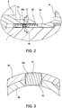
- FIG. 2 is an enlarged view of an II part in FIG. 1 , showing an enlarged view of the pin member 21 and its surroundings, and is shown omitting the members other than the shaft 1, the cylinder block 2, and the front cover 4.
- FIG. 3 is a view showing a section taken on line III-III in FIG. 2 , in an enlarged manner.
- the pin member 21 is press fitted into a through hole 20a that penetrates through the first slide bearing 20, and a fixing hole 4c that penetrates through the extending portion 4b.
- the through hole 20a and the fixing hole 4c are formed by common hole machining in a state in which the first slide bearing 20 is press fitted into the outer circumferential surface of the extending portion 4b. Since the pin member 21 attaches closely to the through hole 20a and the fixing hole 4c, the loosening of the first slide bearing 20 with respect to the extending portion 4b and the coming off of the first slide bearing 20 from the extending portion 4b is prevented.
- the length of the pin member 21 in the press fitting direction is, as shown in FIG.
- the pin member 21 will not be in contact with the sliding contact portion 2c with which the first slide bearing 20 is brought into sliding contact and the shaft 1 that is adjacent to the inner circumferential side of the extending portion 4b.
- the first slide bearing 20 is press fitted into the outer circumferential surface of the extending portion 4b, however the first slide bearing 20 may be formed on the outer circumferential surface of the extending portion 4b by molding.
- the fixing hole 4c formed in the extending portion 4b penetrates through the extending portion 4b.
- the fixing hole 4c may be formed as a bottomed hole closed on the shaft 1 side.
- the pin member 21 is regulated in movement to the shaft 1 side by abutting to a bottom portion of the fixing hole 4c, and thus positioning thereof is carried out easily.
- a locking screw may be used instead of the pin member 21.
- a female thread portion is fabricated on both or either one of the fixing hole 4c of the extending portion 4b and the through hole 20a of the first slide bearing 20. The screwing of the locking screw to this female thread portion allows for preventing the loosening of the first slide bearing 20 with respect to the extending portion 4b and the first slide bearing 20 coming off from the extending portion 4b.
- a supply passage 8 that guides water to be sucked into the capacity chamber 7 and a discharge passage 9 that guides water discharged from the capacity chamber 7 are formed in the end cover 5.
- the end cover 5 further includes a third slide bearing 18 that fits to the inner circumferential surface of the accommodating recessed portion 5a.
- the end cover 5 supports the one end portion 1 a of the shaft 1 that is accommodated in the accommodating recessed portion 5a in a rotatable manner, via the third slide bearing 18.
- the first to third slide bearings 18 to 20 are formed of resin, ceramic, DLC (Diamond Like Carbon) or like material.
- the material of the first to third slide bearings 18 to 20 may be any material as long as it can ensure slidability, particularly even when the working fluid is water.
- the piston pump 100 further includes a valve plate 17 interposed between the cylinder block 2 and the end cover 5.
- the valve plate 17 is a disc member with which a base end surface of the cylinder block 2 is brought into sliding contact, and is fixed to the end cover 5.
- a supply port 17a connecting the supply passage 8 with the capacity chamber 7, and a discharge port 17b connecting the discharge passage 9 with the capacity chamber 7, are formed in the valve plate 17.
- Water is guided to the capacity chamber 7 that is enlarged by rotation of the cylinder block 2, through the supply passage 8 and the supply port 17a. Pressure of the water suctioned into the capacity chamber 7 is boosted by reduction of the capacity chambers 7 due to the rotation of the cylinder block 2, and the water is discharged through the discharge port 17b and the discharge passage 9. In such a way, suction and discharge of the water are continuously performed in accordance with the rotation of the cylinder block 2, in the piston pump 100.
- the first slide bearing 20 is provided between the extending portion 4b of the front cover 4 and the cylinder block 2, there is no need to form a sliding contact portion that is brought into sliding contact with the bearing, on the outer circumferential surface of the cylinder block 2. Accordingly, the outer diameter of the cylinder block 2 is made smaller, thus allowing for making the hydraulic rotary machine 100 compact.
- the diameter of the bearing becomes smaller than a case in which the slide bearing is provided between the outer circumference of the cylinder block 2 and the inner circumference of the casing 3, and thus a range in which the bearing is disposed becomes narrow. This accordingly reduces the amount of bearing material used, which thus allows for the reduction of manufacturing costs.
- the torque that acts on the first slide bearing 20 from the cylinder block 2 increases.
- the first slide bearing 20 is fixed to the front cover 4 by the pin member 21, it is possible to prevent the loosening of the first slide bearing 20, and it is possible to prevent the first slide bearing 20 from falling off from the front cover 4.
- FIG. 4 and FIG. 5 are drawings that correspond to FIG. 2 .
- a projection portion 20b that projects inwards in the radial direction is formed on the inner circumferential surface of the first slide bearing 20, and a locking recessed portion 4d to which the projection portion 20b of the first slide bearing 20 locks is formed on the outer circumference surface of the extending portion 4b.
- the first sliding bearing 20 is fixed to the extending portion 4b by a locking structure in which the projection portion 20b engages with the locking recessed portion 4d. Therefore, also in the first modified example, effects are obtained as with the above embodiment that the loosening of the first slide baring 20 can be prevented and that the falling off of the first slide bearing 20 from the front cover 4 can be prevented.
- the projection portion 20b and the locking recessed portion 4d may be formed along the whole circumference, or a plurality thereof may be formed along the circumferential direction. Moreover, the projection portion 20b and the locking recessed portion 4d may be provided at any position in the axial direction of the first slide bearing 20. Moreover, in the first modified example, the projection portion 20b is formed on the first slide bearing 20 side and the locking recessed portion 4d is formed on the extending portion 4b side. However, instead of this, the projection portion may be formed on the extending portion 4b side and the locking recessed portion may be formed on the first slide bearing 20 side.
- the first slide bearing 20 may be formed of resin material, and in this case, the first slide bearing 20 is molded to the extending portion 4b. By engaging the projection portion 20b formed by molding with the locking recessed portion 4d, the first slide bearing 20 is fixed to the extending portion 4b. In order to improve the adhesiveness of the molding, a plurality of rugged portions may be further provided on the outer circumferential surface of the extending portion 4b.
- a female thread 20c is formed on the inner circumferential surface of the first slide bearing 20, and a male thread 4e that screws to the female thread 20c of the first slide bearing 20 is formed on the outer circumferential surface of the extending portion 4b.
- an adhesive may be used as an independent fixing means for fixing the first slide bearing 20.
- the adhesive is applied on a contacting surface of the first slide bearing 20 and the extending portion 4b, and the first slide bearing 20 is bonded to the extending portion 4b via the adhesive.
- the adhesive is used as the fixing means, the effects are obtained as with the above embodiments that the loosening of the first slide bearing 20 can be prevented and that the falling off of the first slide bearing 20 from the front cover 4 can be prevented.
- the fixing means of the first slide bearing 20 is not limited to these, and may be of any form as long as it prevents the first slide bearing 20 from coming off from the extending portion 4b.
- the first slide bearing 20 provided between the cylinder block 2 and the front cover 4 is fixed on the front cover 4 side.
- the first slide bearing 20 may be fixed on the cylinder block 2 side.
- the first slide bearing 20 is fixed on the inner circumference side of the sliding contact portion 2c of the cylinder block 2 by any of the above fixing means, and is brought into sliding contact with the outer circumferential surface of the extending portion 4b of the front cover 4.
- the piston pump motor 100 is one whose angle of the swash plate 11 is of a fixed type, this may be a variable capacity type piston pump motor whose tilting angle of the swash plate can be changed.
Landscapes
- Engineering & Computer Science (AREA)
- Mechanical Engineering (AREA)
- General Engineering & Computer Science (AREA)
- Chemical & Material Sciences (AREA)
- Combustion & Propulsion (AREA)
- Reciprocating Pumps (AREA)
- Details Of Reciprocating Pumps (AREA)
- Hydraulic Motors (AREA)
Abstract
Description
- The present invention relates to a hydraulic rotary machine used as a piston pump or a piston motor.
- For example, a piston pump described in
JP2005-133647A JP2005-133647A - However, the axial piston pump including a bearing between an outer circumference of a cylinder block and an inner circumference of a casing requires forming a sliding contact portion brought into sliding contact with the bearing by extending from an outer circumferential surface of the cylinder block, and requires securing a space for disposing the bearing on the inner circumferential side of the case. Therefore, there was the problem that the outer diameter of the pump increases in size. Moreover, since the range that the bearing is provided is broad, the amount of material used for the bearing increases, which thus causes the problem of high material costs. In order to overcome such problems, considerations may be made to dispose the bearing on the shaft side of the cylinder block, however when a large torque acts on the bearing, the bearing may loosen and the function as a bearing may not be exhibited.
- An object of the present invention is to make a hydraulic rotary machine compact and prevent the loosening of a bearing.
- According to one aspect of the present invention, a hydraulic rotary machine includes a plurality of pistons, a rotatable cylinder block including a plurality of cylinders for accommodating the pistons, a shaft penetrating through the cylinder block and coupling to the cylinder block, a swash plate configured to cause reciprocation of the piston in accordance with the rotation of the cylinder block so as to expand and contract a capacity chamber of the cylinder, a case member supporting one end of the shaft and accommodating the cylinder block, a cover member through which the other end of the shaft is inserted, the cover member closing an opened end of the case member, an extending portion formed in the cover member, the extending portion extending along the shaft towards the cylinder block, and a first slide bearing provided between the extending portion and the cylinder block. The first slide bearing is fixed to the extending portion or the cylinder block by a fixing means.
-
-
FIG. 1 is a sectional view of a hydraulic rotary machine according to an embodiment of the present invention; -
FIG. 2 is an enlarged view of an II part inFIG. 1 ; -
FIG. 3 is a sectional view taken on line III-III inFIG. 2 ; -
FIG. 4 is a view showing a first modified example of a fixing means; and -
FIG. 5 is a view showing a second modified example of the fixing means. - Hereinafter, a hydraulic rotary machine according to an embodiment of the present invention will be described with reference to the drawings.
- The present embodiment describes a case where the hydraulic rotary machine is a hydraulic
piston pump motor 100 in which water serves as a working fluid. As shown inFIG. 1 , the hydraulicpiston pump motor 100 functions as a pump that supplies water serving as the working fluid, by ashaft 1 rotating due to extraneous power andpistons 6 reciprocating due to the rotation, and functions as a motor that outputs rotation drive force, by thepistons 6 reciprocating by fluid pressure of water extraneously supplied and theshaft 1 rotating due to the reciprocation. - The description hereinafter exemplifies a case in which the hydraulic
piston pump motor 100 is used as a piston pump, and the hydraulicpiston pump motor 100 will simply be called as the "piston pump 100". - The
piston pump 100 is a hydraulic piston pump in which water serves as the working fluid. Thepiston pump 100 includes ashaft 1 that rotates by a power source, acylinder block 2 coupled to theshaft 1 and which rotates in accordance with the rotation of theshaft 1, and acasing 3 that accommodates thecylinder block 2. Thecasing 3 includes a casemain body 3a whose both ends are opened, an end cover 5 that supports one end of theshaft 1 and closes one of the opened ends of the casemain body 3a, and afront cover 4 through which the other end of theshaft 1 is inserted and which serves as a cover member for closing the other one of the opened ends of the casemain body 3a. - Here, the case
main body 3a coupled with the end cover 5 corresponds to the case member recited in the claims. In the present embodiment, the casemain body 3a and the end cover 5 are formed as separate members. Instead of this, the casemain body 3a and the end cover 5 may be formed integrally. In this case, the casemain body 3a and the end cover 5 that is integrally formed will correspond to the case member recited in the claims. - The one
end portion 1a of theshaft 1 is accommodated in an accommodating recessedportion 5a provided in the end cover 5. Theother end portion 1b of theshaft 1 projects externally from thefront cover 4, and is coupled to the power source. - The
cylinder block 2 has a throughhole 2a through which theshaft 1 penetrates, and is splined to theshaft 1 at acoupling portion 50. Accordingly, thecylinder block 2 rotates in accordance with the rotation of theshaft 1. - In the
cylinder block 2, a plurality ofcylinders 2b having an opening on one end surface thereof is formed in parallel to theshaft 1. The plurality ofcylinders 2b is formed at predetermined intervals in a circumferential direction of thecylinder block 2. Acylindrical piston 6 that partitions acapacity chamber 7 is inserted into thecylinder 2b in a reciprocatable manner. A leading end side of thepiston 6 projects from the opening of thecylinder 2b, and aspherical base 6a is formed on a leading end portion thereof. - The
piston pump 100 further includesshoes 10 respectively coupled to the leading end portions of thepistons 6 in a rotatable manner, and swash plates 11 with which a respective one of theshoes 10 is brought into sliding contact in accordance with the rotation of thecylinder block 2. - The
shoe 10 includes a receivingportion 10a that receives thespherical base 6a formed on the leading end of thepiston 6, and a circular flat plate portion 10b that is brought into sliding contact with the swash plate 11. An inner surface of thereceiving portion 10a is formed in a spherical shape, and is brought into sliding contact with an outer surface of the receivedspherical base 6a. Theshoe 10 is displaceable in angle in any direction with respect to thespherical base 6a. - The swash plate 11 is fixed to an inner wall of the
front cover 4, and has a sliding contact surface 11 a tilted from a direction perpendicular to an axis of theshaft 1. The flat plate portion 10b of theshoe 10 is brought into surface contact with the sliding contact surface 11 a. - A through
hole 4a through which theshaft 1 is inserted is formed in thefront cover 4. A second slide bearing 19 that supports theshaft 1 in a rotatable manner is fitted to the throughhole 4a. Moreover, thefront cover 4 is provided with sealingmaterial 25 so that water does not leak outside from between theshaft 1 and thefront cover 4. - The
front cover 4 further has a tubular extendingportion 4b formed thereto, which tubular extendingportion 4b extends towards thecylinder block 2 along theshaft 1. A first slide bearing 20 is press fitted to an outer circumferential surface of the extendingportion 4b. A tubular slidingcontact portion 2c is formed in thecylinder block 2 that is positioned facing the outer circumferential surface of the extendingportion 4b, and the tubular slidingcontact portion 2c is brought into sliding contact with the first slide bearing 20. Since the inner circumferential surface of the slidingcontact portion 2c is brought into sliding contact with the outer circumferential surface of the first slide bearing 20, thecylinder block 2 is supported in a rotatable manner by thefront cover 4. - Here, a torque from the
rotatable cylinder block 2 acts on the first slide bearing 20 press fitted into the outer circumferential surface of the extendingportion 4b. When this torque is large, the press fitting of the first slide bearing 20 may loosen. Thereby, this may cause the first slide bearing 20 to loosen with respect to the extendingportion 4b or to come off from the extendingportion 4b. Therefore, the first slide bearing 20 must be securely fixed to the extendingportion 4b. - In the present embodiment, the first slide bearing 20 is fixed to the extending
portion 4b by apin member 21 serving as a fixing means, as shown in an enlarged manner inFIG. 2 and FIG. 3. FIG. 2 is an enlarged view of an II part inFIG. 1 , showing an enlarged view of thepin member 21 and its surroundings, and is shown omitting the members other than theshaft 1, thecylinder block 2, and thefront cover 4.FIG. 3 is a view showing a section taken on line III-III inFIG. 2 , in an enlarged manner. - As shown in
FIG. 2 and FIG. 3 , thepin member 21 is press fitted into athrough hole 20a that penetrates through the first slide bearing 20, and afixing hole 4c that penetrates through the extendingportion 4b. The throughhole 20a and thefixing hole 4c are formed by common hole machining in a state in which the first slide bearing 20 is press fitted into the outer circumferential surface of the extendingportion 4b. Since thepin member 21 attaches closely to the throughhole 20a and thefixing hole 4c, the loosening of the first slide bearing 20 with respect to the extendingportion 4b and the coming off of the first slide bearing 20 from the extendingportion 4b is prevented. Moreover, the length of thepin member 21 in the press fitting direction is, as shown inFIG. 3 , set to not project out from the outer circumferential surface of the first slide bearing 20 and the inner circumferential surface of the extendingportion 4b. Therefore, thepin member 21 will not be in contact with the slidingcontact portion 2c with which the first slide bearing 20 is brought into sliding contact and theshaft 1 that is adjacent to the inner circumferential side of the extendingportion 4b. In the present embodiment, the first slide bearing 20 is press fitted into the outer circumferential surface of the extendingportion 4b, however the first slide bearing 20 may be formed on the outer circumferential surface of the extendingportion 4b by molding. - Moreover, in the present embodiment, the fixing
hole 4c formed in the extendingportion 4b penetrates through the extendingportion 4b. Instead of this, the fixinghole 4c may be formed as a bottomed hole closed on theshaft 1 side. In this case, thepin member 21 is regulated in movement to theshaft 1 side by abutting to a bottom portion of the fixinghole 4c, and thus positioning thereof is carried out easily. - Moreover, as the fixing means, a locking screw may be used instead of the
pin member 21. In this case, a female thread portion is fabricated on both or either one of the fixinghole 4c of the extendingportion 4b and the throughhole 20a of thefirst slide bearing 20. The screwing of the locking screw to this female thread portion allows for preventing the loosening of the first slide bearing 20 with respect to the extendingportion 4b and the first slide bearing 20 coming off from the extendingportion 4b. - As shown in
FIG. 1 , asupply passage 8 that guides water to be sucked into thecapacity chamber 7 and adischarge passage 9 that guides water discharged from thecapacity chamber 7 are formed in the end cover 5. The end cover 5 further includes a third slide bearing 18 that fits to the inner circumferential surface of the accommodating recessedportion 5a. The end cover 5 supports the oneend portion 1 a of theshaft 1 that is accommodated in the accommodating recessedportion 5a in a rotatable manner, via thethird slide bearing 18. - The first to
third slide bearings 18 to 20 are formed of resin, ceramic, DLC (Diamond Like Carbon) or like material. The material of the first tothird slide bearings 18 to 20 may be any material as long as it can ensure slidability, particularly even when the working fluid is water. - The
piston pump 100 further includes avalve plate 17 interposed between thecylinder block 2 and the end cover 5. - The
valve plate 17 is a disc member with which a base end surface of thecylinder block 2 is brought into sliding contact, and is fixed to the end cover 5. Asupply port 17a connecting thesupply passage 8 with thecapacity chamber 7, and adischarge port 17b connecting thedischarge passage 9 with thecapacity chamber 7, are formed in thevalve plate 17. - Next, actions of the
piston pump 100 will be described. - When the
shaft 1 is driven and rotated by extraneous power and thecylinder block 2 is rotated in accordance with the rotation of theshaft 1, the flat plate portions 10b of theshoes 10 are brought into sliding contact with the respective swash plate 11, and thepistons 6 reciprocate within thecylinders 2b by a stroke amount in accordance with a tilting angle of the swash plate 11. The reciprocation of thepistons 6 causes the capacities of thecapacity chambers 7 to increase or decrease. - Water is guided to the
capacity chamber 7 that is enlarged by rotation of thecylinder block 2, through thesupply passage 8 and thesupply port 17a. Pressure of the water suctioned into thecapacity chamber 7 is boosted by reduction of thecapacity chambers 7 due to the rotation of thecylinder block 2, and the water is discharged through thedischarge port 17b and thedischarge passage 9. In such a way, suction and discharge of the water are continuously performed in accordance with the rotation of thecylinder block 2, in thepiston pump 100. - According to the above embodiment, the following effects are achieved.
- Since the first slide bearing 20 is provided between the extending
portion 4b of thefront cover 4 and thecylinder block 2, there is no need to form a sliding contact portion that is brought into sliding contact with the bearing, on the outer circumferential surface of thecylinder block 2. Accordingly, the outer diameter of thecylinder block 2 is made smaller, thus allowing for making the hydraulicrotary machine 100 compact. - Moreover, since the first slide bearing 20 is provided between the extending
portion 4b of thefront cover 4 and thecylinder block 2, the diameter of the bearing becomes smaller than a case in which the slide bearing is provided between the outer circumference of thecylinder block 2 and the inner circumference of thecasing 3, and thus a range in which the bearing is disposed becomes narrow. This accordingly reduces the amount of bearing material used, which thus allows for the reduction of manufacturing costs. - Meanwhile, as the area of the bearing is reduced, the torque that acts on the first slide bearing 20 from the
cylinder block 2 increases. However, since the first slide bearing 20 is fixed to thefront cover 4 by thepin member 21, it is possible to prevent the loosening of thefirst slide bearing 20, and it is possible to prevent the first slide bearing 20 from falling off from thefront cover 4. - Moreover, since slide bearings formed of material that can secure slidability even when the working fluid is water are used as the
bearings 18 to 20, problems such as seizing will not occur even in a case in which water having low lubricity is used as the working fluid. Furthermore, in the present embodiment, the rotational object including theshaft 1 and thecylinder block 2 is supported by three slide bearings; accordingly, contact pressure applied on each of the slide bearings is dispersed. Therefore, it is possible to improve the durability of the hydraulic rotary machine even in a case in which water having poor lubricity is used as the working fluid. - Hereinafter, a modified example of the aforementioned fixing means will be described with reference to
FIG. 4 and FIG. 5. FIG. 4 and FIG. 5 are drawings that correspond toFIG. 2 . - In the first modified example shown in
FIG. 4 , as a fixing means, aprojection portion 20b that projects inwards in the radial direction is formed on the inner circumferential surface of thefirst slide bearing 20, and a locking recessedportion 4d to which theprojection portion 20b of the first slide bearing 20 locks is formed on the outer circumference surface of the extendingportion 4b. The first slidingbearing 20 is fixed to the extendingportion 4b by a locking structure in which theprojection portion 20b engages with the locking recessedportion 4d. Therefore, also in the first modified example, effects are obtained as with the above embodiment that the loosening of the first slide baring 20 can be prevented and that the falling off of the first slide bearing 20 from thefront cover 4 can be prevented. - In the first modified example, the
projection portion 20b and the locking recessedportion 4d may be formed along the whole circumference, or a plurality thereof may be formed along the circumferential direction. Moreover, theprojection portion 20b and the locking recessedportion 4d may be provided at any position in the axial direction of thefirst slide bearing 20. Moreover, in the first modified example, theprojection portion 20b is formed on the first slide bearing 20 side and the locking recessedportion 4d is formed on the extendingportion 4b side. However, instead of this, the projection portion may be formed on the extendingportion 4b side and the locking recessed portion may be formed on the first slide bearing 20 side. - Moreover, in the first modified example, the first slide bearing 20 may be formed of resin material, and in this case, the first slide bearing 20 is molded to the extending
portion 4b. By engaging theprojection portion 20b formed by molding with the locking recessedportion 4d, the first slide bearing 20 is fixed to the extendingportion 4b. In order to improve the adhesiveness of the molding, a plurality of rugged portions may be further provided on the outer circumferential surface of the extendingportion 4b. - In the second modified example shown in
FIG. 5 , afemale thread 20c is formed on the inner circumferential surface of thefirst slide bearing 20, and amale thread 4e that screws to thefemale thread 20c of the first slide bearing 20 is formed on the outer circumferential surface of the extendingportion 4b. By screwing the first slide bearing 20 in the same direction as the rotational direction of thecylinder block 2 to themale thread 4e of the extendingportion 4b, the first slide bearing 20 is fixed to the extendingportion 4b. If the direction in which the first slide bearing 20 is screwed and the rotational direction of thecylinder block 2 are the same, the first slide bearing 20 will not loosen. Accordingly, in a case in which the hydraulicrotary machine 100 is used as a piston pump whose rotational direction of thecylinder block 2 is constant, this is particularly useful. Therefore, also in the second modified example, the effects are obtained as with the above embodiments that the loosening of the first slide bearing 20 can be prevented and that the falling off of the first slide bearing 20 from thefront cover 4 can be prevented. - Together with the above fixing means, or alternatively, as an independent fixing means for fixing the
first slide bearing 20, an adhesive may be used. The adhesive is applied on a contacting surface of thefirst slide bearing 20 and the extendingportion 4b, and the first slide bearing 20 is bonded to the extendingportion 4b via the adhesive. Even in the case in which the adhesive is used as the fixing means, the effects are obtained as with the above embodiments that the loosening of the first slide bearing 20 can be prevented and that the falling off of the first slide bearing 20 from thefront cover 4 can be prevented. The fixing means of the first slide bearing 20 is not limited to these, and may be of any form as long as it prevents the first slide bearing 20 from coming off from the extendingportion 4b. - In the above embodiment, the first modified example, and the second modified example, the first slide bearing 20 provided between the
cylinder block 2 and thefront cover 4 is fixed on thefront cover 4 side. Instead of this, the first slide bearing 20 may be fixed on thecylinder block 2 side. In this case, the first slide bearing 20 is fixed on the inner circumference side of the slidingcontact portion 2c of thecylinder block 2 by any of the above fixing means, and is brought into sliding contact with the outer circumferential surface of the extendingportion 4b of thefront cover 4. - The embodiments of the present invention described above are merely illustration of some application examples of the present invention and not of the nature to limit the technical scope of the present invention to the specific constructions of the above embodiments.
- In the prevent embodiment, although water is used as the working fluid, a working fluid such as working oil or an aqueous alternative fluid may be used instead of this. Moreover, although the
piston pump motor 100 is one whose angle of the swash plate 11 is of a fixed type, this may be a variable capacity type piston pump motor whose tilting angle of the swash plate can be changed. - The present application claims a priority based on Japanese Patent Application No.
2014-139540
Claims (8)
- A hydraulic rotary machine comprising:a plurality of pistons;a rotatable cylinder block including a plurality of cylinders for accommodating the pistons;a shaft penetrating through the cylinder block and coupling to the cylinder block;a swash plate configured to cause reciprocation of the piston in accordance with the rotation of the cylinder block so as to expand and contract a capacity chamber of the cylinder;a case member supporting one end of the shaft and accommodating the cylinder block;a cover member through which the other end of the shaft is inserted, the cover member closing an opened end of the case member;an extending portion formed in the cover member, the extending portion extending along the shaft towards the cylinder block; anda first slide bearing provided between the extending portion and the cylinder block, whereinthe first slide bearing is fixed to the extending portion or the cylinder block by a fixing means.
- The hydraulic rotary machine according to claim 1, wherein
the fixing means comprises a pin member penetrating through the first slide bearing, and a leading end portion of the pin member fits into a hole provided in the extending portion or the cylinder block. - The hydraulic rotary machine according to claim 1, wherein
the fixing means comprises a locking screw penetrating through the first slide bearing, and a leading end portion of the locking screw screws into a screw hole provided in the extending portion or the cylinder block. - The hydraulic rotary machine according to claim 1, wherein
the fixing means comprises a locking structure comprisinga bearing side projection portion or a bearing side locking recessed portion formed in the first slide bearing, anda locking recessed portion or a projection portion formed in the extending portion or the cylinder block, the locking recessed portion engaging with the bearing side projection portion, the projection portion engaging with the bearing side locking recessed portion. - The hydraulic rotary machine according to claim 4, wherein
the first slide bearing is formed by molding to the extending portion or the cylinder block. - The hydraulic rotary machine according to claim 1, wherein
the fixing means comprisesa bearing side screw portion formed in the first slide bearing, anda screw portion formed in the extending portion or the cylinder block, the screw portion screwing to the bearing side screw portion. - The hydraulic rotary machine according to claim 1, wherein
the working fluid comprises water. - The hydraulic rotary machine according to claim 1, further comprising:a second slide bearing provided in the cover member, the second slide bearing rotatably supporting an outer circumference of the shaft penetrating through the cover member; anda third slide bearing provided in the case member, the third slide bearing rotatably support one end of the shaft.
Applications Claiming Priority (2)
| Application Number | Priority Date | Filing Date | Title |
|---|---|---|---|
| JP2014139540A JP2016017429A (en) | 2014-07-07 | 2014-07-07 | Hydraulic rotating machine |
| PCT/JP2015/068373 WO2016006466A1 (en) | 2014-07-07 | 2015-06-25 | Hydraulic rotary machine |
Publications (2)
| Publication Number | Publication Date |
|---|---|
| EP3168471A1 true EP3168471A1 (en) | 2017-05-17 |
| EP3168471A4 EP3168471A4 (en) | 2018-02-07 |
Family
ID=55064104
Family Applications (1)
| Application Number | Title | Priority Date | Filing Date |
|---|---|---|---|
| EP15819562.8A Withdrawn EP3168471A4 (en) | 2014-07-07 | 2015-06-25 | Hydraulic rotary machine |
Country Status (6)
| Country | Link |
|---|---|
| US (1) | US20170159638A1 (en) |
| EP (1) | EP3168471A4 (en) |
| JP (1) | JP2016017429A (en) |
| CN (1) | CN106471250A (en) |
| AU (1) | AU2015288848A1 (en) |
| WO (1) | WO2016006466A1 (en) |
Families Citing this family (2)
| Publication number | Priority date | Publication date | Assignee | Title |
|---|---|---|---|---|
| CN111237154B (en) * | 2020-03-02 | 2023-08-04 | 中山市多德立电器有限公司 | Submersible pump |
| CN113653635B (en) * | 2021-08-30 | 2023-06-20 | 北京航空航天大学宁波创新研究院 | A cylinder sliding support structure and a hydraulic plunger pump |
Family Cites Families (10)
| Publication number | Priority date | Publication date | Assignee | Title |
|---|---|---|---|---|
| US3092034A (en) * | 1959-02-18 | 1963-06-04 | Kamper Motoren G M B H | Axial piston engines |
| US3728943A (en) * | 1968-12-03 | 1973-04-24 | Messier Fa | Hydraulic pumps or motors of the rotating barrel type |
| GB1593731A (en) * | 1976-07-26 | 1981-07-22 | Secretary Industry Brit | Axial piston hydraulic machines |
| JPH0697584B2 (en) * | 1991-02-28 | 1994-11-30 | 株式会社ノーリツ | Operation switch for water |
| US5366305A (en) * | 1993-06-09 | 1994-11-22 | Hewlett-Packard Company | Two-line contact carriage bearing subsystem |
| JP3748700B2 (en) * | 1998-02-06 | 2006-02-22 | 光洋精工株式会社 | Rack and pinion type steering device and boot used therefor |
| JP2006135200A (en) * | 2004-11-09 | 2006-05-25 | Neomax Co Ltd | Stage equipment |
| JP2008011812A (en) * | 2006-07-07 | 2008-01-24 | Daiwa Seiko Inc | Fishing reel |
| JP5101122B2 (en) * | 2007-02-02 | 2012-12-19 | Ntn株式会社 | Hydrodynamic bearing device |
| JP6031301B2 (en) * | 2012-09-10 | 2016-11-24 | Kyb株式会社 | Hydraulic rotating machine |
-
2014
- 2014-07-07 JP JP2014139540A patent/JP2016017429A/en active Pending
-
2015
- 2015-06-25 CN CN201580036159.1A patent/CN106471250A/en active Pending
- 2015-06-25 AU AU2015288848A patent/AU2015288848A1/en not_active Abandoned
- 2015-06-25 US US15/324,412 patent/US20170159638A1/en not_active Abandoned
- 2015-06-25 EP EP15819562.8A patent/EP3168471A4/en not_active Withdrawn
- 2015-06-25 WO PCT/JP2015/068373 patent/WO2016006466A1/en not_active Ceased
Also Published As
| Publication number | Publication date |
|---|---|
| CN106471250A (en) | 2017-03-01 |
| AU2015288848A1 (en) | 2017-02-02 |
| US20170159638A1 (en) | 2017-06-08 |
| EP3168471A4 (en) | 2018-02-07 |
| WO2016006466A1 (en) | 2016-01-14 |
| JP2016017429A (en) | 2016-02-01 |
Similar Documents
| Publication | Publication Date | Title |
|---|---|---|
| AU2015272637B9 (en) | Piston pump and valve plate for piston pump | |
| US12025112B2 (en) | Piston body including an internal space for use in a hydraulic pump or motor | |
| US10954936B2 (en) | Axial piston machine with recess in the region of the loading pressure channel | |
| JP4820964B2 (en) | Common pump housing for multiple rated volumes | |
| US10066484B2 (en) | Fluid pressure rotating machine | |
| US20170159638A1 (en) | Hydraulic rotary machine | |
| EP3404260A1 (en) | Variable displacement swash plate type piston pump | |
| US9644480B2 (en) | Fluid pressure rotary machine | |
| US12415491B2 (en) | Pump housing layout for brake system | |
| JP6447362B2 (en) | Variable capacity swash plate type hydraulic rotating machine | |
| JP6569515B2 (en) | Swash plate type piston pump | |
| JPH11210616A (en) | Axial piston type pump | |
| EP3106666B1 (en) | Hydraulic rotary machine | |
| JP2018141389A (en) | Liquid pressure rotary machine | |
| JP6387327B2 (en) | Variable capacity swash plate type hydraulic rotating machine | |
| JP6756290B2 (en) | Manufacturing method of variable capacity type swash plate type piston pump and variable capacity type swash plate type piston pump | |
| JP6572764B2 (en) | Swash plate type piston pump | |
| JP7377027B2 (en) | Swash plate type axial piston pump/motor | |
| JP2015178808A (en) | Hydraulic rotating machine | |
| JP2020026815A (en) | Pumping unit | |
| KR20130109485A (en) | Shaft support structure of a swash plate type compressor | |
| JP6557553B2 (en) | Hydraulic rotating machine | |
| JP2023150122A (en) | Swash plate type axial piston pump/motor | |
| CN117905666A (en) | Fluid machinery | |
| WO2019035355A1 (en) | Hydraulic rotary machine |
Legal Events
| Date | Code | Title | Description |
|---|---|---|---|
| PUAI | Public reference made under article 153(3) epc to a published international application that has entered the european phase |
Free format text: ORIGINAL CODE: 0009012 |
|
| 17P | Request for examination filed |
Effective date: 20170109 |
|
| AK | Designated contracting states |
Kind code of ref document: A1 Designated state(s): AL AT BE BG CH CY CZ DE DK EE ES FI FR GB GR HR HU IE IS IT LI LT LU LV MC MK MT NL NO PL PT RO RS SE SI SK SM TR |
|
| AX | Request for extension of the european patent |
Extension state: BA ME |
|
| DAV | Request for validation of the european patent (deleted) | ||
| DAX | Request for extension of the european patent (deleted) | ||
| A4 | Supplementary search report drawn up and despatched |
Effective date: 20180108 |
|
| RIC1 | Information provided on ipc code assigned before grant |
Ipc: F03C 1/06 20060101AFI20180102BHEP Ipc: F04B 1/20 20060101ALI20180102BHEP |
|
| STAA | Information on the status of an ep patent application or granted ep patent |
Free format text: STATUS: THE APPLICATION HAS BEEN WITHDRAWN |
|
| 18W | Application withdrawn |
Effective date: 20181128 |