EP3168161A1 - System of driving channels for a carriage for transporting airplanes on an airport apron - Google Patents
System of driving channels for a carriage for transporting airplanes on an airport apron Download PDFInfo
- Publication number
- EP3168161A1 EP3168161A1 EP16460085.0A EP16460085A EP3168161A1 EP 3168161 A1 EP3168161 A1 EP 3168161A1 EP 16460085 A EP16460085 A EP 16460085A EP 3168161 A1 EP3168161 A1 EP 3168161A1
- Authority
- EP
- European Patent Office
- Prior art keywords
- channels
- channel segments
- channel
- carriage
- location
- Prior art date
- Legal status (The legal status is an assumption and is not a legal conclusion. Google has not performed a legal analysis and makes no representation as to the accuracy of the status listed.)
- Granted
Links
Images






Classifications
-
- B—PERFORMING OPERATIONS; TRANSPORTING
- B64—AIRCRAFT; AVIATION; COSMONAUTICS
- B64F—GROUND OR AIRCRAFT-CARRIER-DECK INSTALLATIONS SPECIALLY ADAPTED FOR USE IN CONNECTION WITH AIRCRAFT; DESIGNING, MANUFACTURING, ASSEMBLING, CLEANING, MAINTAINING OR REPAIRING AIRCRAFT, NOT OTHERWISE PROVIDED FOR; HANDLING, TRANSPORTING, TESTING OR INSPECTING AIRCRAFT COMPONENTS, NOT OTHERWISE PROVIDED FOR
- B64F1/00—Ground or aircraft-carrier-deck installations
- B64F1/22—Ground or aircraft-carrier-deck installations for handling aircraft
-
- B—PERFORMING OPERATIONS; TRANSPORTING
- B64—AIRCRAFT; AVIATION; COSMONAUTICS
- B64F—GROUND OR AIRCRAFT-CARRIER-DECK INSTALLATIONS SPECIALLY ADAPTED FOR USE IN CONNECTION WITH AIRCRAFT; DESIGNING, MANUFACTURING, ASSEMBLING, CLEANING, MAINTAINING OR REPAIRING AIRCRAFT, NOT OTHERWISE PROVIDED FOR; HANDLING, TRANSPORTING, TESTING OR INSPECTING AIRCRAFT COMPONENTS, NOT OTHERWISE PROVIDED FOR
- B64F1/00—Ground or aircraft-carrier-deck installations
- B64F1/002—Taxiing aids
-
- B—PERFORMING OPERATIONS; TRANSPORTING
- B64—AIRCRAFT; AVIATION; COSMONAUTICS
- B64F—GROUND OR AIRCRAFT-CARRIER-DECK INSTALLATIONS SPECIALLY ADAPTED FOR USE IN CONNECTION WITH AIRCRAFT; DESIGNING, MANUFACTURING, ASSEMBLING, CLEANING, MAINTAINING OR REPAIRING AIRCRAFT, NOT OTHERWISE PROVIDED FOR; HANDLING, TRANSPORTING, TESTING OR INSPECTING AIRCRAFT COMPONENTS, NOT OTHERWISE PROVIDED FOR
- B64F1/00—Ground or aircraft-carrier-deck installations
- B64F1/22—Ground or aircraft-carrier-deck installations for handling aircraft
- B64F1/223—Ground or aircraft-carrier-deck installations for handling aircraft for towing aircraft
- B64F1/225—Vehicles specially adapted therefor, e.g. aircraft tow tractors
- B64F1/227—Vehicles specially adapted therefor, e.g. aircraft tow tractors for direct connection to aircraft, e.g. tow tractors without towing bars
-
- B—PERFORMING OPERATIONS; TRANSPORTING
- B64—AIRCRAFT; AVIATION; COSMONAUTICS
- B64F—GROUND OR AIRCRAFT-CARRIER-DECK INSTALLATIONS SPECIALLY ADAPTED FOR USE IN CONNECTION WITH AIRCRAFT; DESIGNING, MANUFACTURING, ASSEMBLING, CLEANING, MAINTAINING OR REPAIRING AIRCRAFT, NOT OTHERWISE PROVIDED FOR; HANDLING, TRANSPORTING, TESTING OR INSPECTING AIRCRAFT COMPONENTS, NOT OTHERWISE PROVIDED FOR
- B64F1/00—Ground or aircraft-carrier-deck installations
- B64F1/22—Ground or aircraft-carrier-deck installations for handling aircraft
- B64F1/223—Ground or aircraft-carrier-deck installations for handling aircraft for towing aircraft
- B64F1/225—Vehicles specially adapted therefor, e.g. aircraft tow tractors
- B64F1/228—Vehicles specially adapted therefor, e.g. aircraft tow tractors remotely controlled; operating autonomously
-
- B—PERFORMING OPERATIONS; TRANSPORTING
- B64—AIRCRAFT; AVIATION; COSMONAUTICS
- B64F—GROUND OR AIRCRAFT-CARRIER-DECK INSTALLATIONS SPECIALLY ADAPTED FOR USE IN CONNECTION WITH AIRCRAFT; DESIGNING, MANUFACTURING, ASSEMBLING, CLEANING, MAINTAINING OR REPAIRING AIRCRAFT, NOT OTHERWISE PROVIDED FOR; HANDLING, TRANSPORTING, TESTING OR INSPECTING AIRCRAFT COMPONENTS, NOT OTHERWISE PROVIDED FOR
- B64F1/00—Ground or aircraft-carrier-deck installations
- B64F1/26—Ground or aircraft-carrier-deck installations for reducing engine or jet noise; Protecting airports from jet erosion
Definitions
- the invention concerns a system of driving channels for a carriage for transporting airplanes on an airport apron from a parking location to a take-off location or from a landing location to a parking location or for example servicing location or fueling location.
- the solution is applicable in the field of aviation.
- the assembly comprises docking stations made in a surface of access ways (taxiways) to a runway of an airport and connected to guiding grooves located along the route of an airplane movement to a parking location.
- the docking stations there are mounted leading mandrels, which are preferably fastened to the front wheel of the airplane after bringing it to the docking station. From the main transport route terminal transport routes are branched off. Guiding grooves which constitute them are covered from the top with pivotable gratings having a segmented structure.
- the pivotable gratings automatically open in front of the leading mandrel moving in the guiding groove. After passage of the leading mandrel, the pivotable gratings close. In places where the guiding grooves change their direction, in places of their abrupt curves and in junctions of the main transport route to the terminal transport route switching devices are installed.
- a carriage assembly intended for a system for transporting airplanes on the airport apron, from a parking location to a runway and from a landing location to a parking location, where a system for transporting airplanes on the airport apron is formed by guiding channels.
- leading mandrels are movable, said mandrels being installed in docking stations and hook-mounted to the airplane, and the guiding channels are covered from the top by pivotable plates of a segmented structure.
- the carriage assembly provides a guiding channel of a rectangular cross-section the bottom of which is provided with lower guiding rails and its sidewalls are provided with side guiding rails and a carriage that constitute a spatial constructions.
- the carriage construction has a bottom part and side parts.
- the carriage is provided with a set of lower ground wheels seated in the bottom part of the carriage and a set of side ground wheels seated in both side parts of the carriage.
- the objective of the solution according to the present invention is to develop a system of driving channels for a carriage that transports airplanes on the airport apron, in particular from a landing location to a parking location and from a parking location to a take-off location.
- the system of channels is intended to provide easy assembling thereof on an existing airport apron in a fast and safe manner, since it may be implemented stepwise, and causes making inoperative only a small area of the airport apron for the time necessary for installing the system, and as a result of the use of this system an airplane will be lighter, more cost-effective in use an will decrease emission of toxins into the environment as well as enhance safety during taxing by means of automatics that controls airplane traffic within the airport.
- a carriage assembly is intended for a system for transporting airplanes on the airport apron, from a parking location to a runway and from a landing location to a parking location, where the system for transporting airplanes on the airport apron is formed by guiding channels.
- leading mandrels are movable, and the mandrels are installed in docking stations and hook-mounted to the airplane, and the guiding channels are covered from the top by pivotable plates of a segmented structure.
- a system of driving channels for a carriage for transporting airplanes on the airport apron, with an actuator or a mandrel with a basket seated thereon and movable in the channels arranged into taxi routes from an airplane landing location to a parking location and from a parking location to a take-off location is characterized in that the channels are formed by channel segments, where the channel segments are depressed in the airport apron so as their top surface is flush with the surface of the airport apron.
- channel segments comprise straight channel segments.
- channel segments comprise crossing channel segments.
- channel segments comprise bifurcating channel segments.
- channel segments comprise turning channel segments.
- taxi transporting routes and terminal transporting routes are defined.
- each of the channel segments is provided with at least one driving unit, comprising a motor and a transmission gear, that puts in motion a carriage that transports the airplane, where said motor may be an electric, pneumatic, hydraulic or combustion motor, and said transmission gear may be a friction gear, toothed gear, tension gear, chain gear, belt or band transmission, shaft gear.
- driving unit comprising a motor and a transmission gear, that puts in motion a carriage that transports the airplane
- said motor may be an electric, pneumatic, hydraulic or combustion motor
- said transmission gear may be a friction gear, toothed gear, tension gear, chain gear, belt or band transmission, shaft gear.
- the driving unit comprises magnetic drive.
- channel segments along their entire length are provided at their upper surface with pivoting plates of a segmented structure, openable when necessary.
- the pivoting plates are provided with a slot in which actuators seated in the transporting carriage are movable, where the actuators carry a basket for of the transporting carriage, in which the front wheel of the airplane being transported is seated.
- the channel segments at their entire length are provided at their upper surface with slidable plates of a segmented structure, openable when necessary.
- the slidable plates are provided with a slot in which actuators seated in the transporting carriage are movable, the actuators carry a basket of the transporting carriage, in which the wheel(s) of the airplane being transported is/are seated.
- activating and stopping of the individual motors and gears of the driving units in the channel segments that transport airplanes is controlled fully automatically and is monitored by the ground personnel of the airport, preferably in cooperation with the pilot of the airplane.
- an airport intended for taking-off and landing planes 3 has an airport apron 4 where take-off/landing locations as well as parking locations for planes 3 are defined. From such take-off/landing location of a plane 3 to a parking location the airplane 3 has to be transferred on the airport apron 4, and for this purpose driving channels 1 are formed in the airport apron 4, as schematically presented in Fig.1 .
- a transporting carriage 2 is movable, which has a carriage actuator 15 and a basket 16, seated thereon, in which basket a wheel 17 of an airplane 3 is positioned, as shown in Fig. 2 , Fig. 8 , and Fig. 11 .
- the front wheel of the airplane 3 is positioned on the basket 16 of the transporting carriage 2 .
- the term front wheel 17 of the airplane 3 also includes a front wheel assembly that may comprise more wheels, for example twin wheels.
- Fig. 2 shows schematically a wheel 17 of an airplane 3 seated on a basket 16 of a transporting carriage 2 located within a driving channel 1, which is not visible during movement of the transporting carriage 2 within the driving channel 1, since the driving channel 1 is covered with a pivotable plate 13.
- This plate may be pivoted upward, as shown in Fig. 9 , or moved slidably aside so as to open the driving channel 1, as shown in Fig. 2 and Fig. 8 .
- the driving channel 1, within which the transporting carriage 2 is moved for transporting airplanes 3 from a take-off/landing location to a parking location, has to be routed in a way so as to enable movement of the airplane 3 between these locations. Therefore it has to cover a considerable part of the airport apron 4 which involves certain problems during laying the transporting channel 1 on the existing airports and, at a lesser extent, on airports under construction.
- the driving channel 1 is formed of channel segments 5 that in fact constitute subsequent lengths of the driving channel 1 being built.
- Channel segments 5 are shown in Fig. 2 , Fig. 4 , Fig. 5 , Fig. 6 , Fig. 7 as well as in Fig. 8 and Fig. 11 .
- the driving channel 1 may be routed along a path with turns, bifurcations, and crossings, channel segments 5 have to allow for such instances.
- the system of driving channels 1 for a carriage 2 that transports airplanes 3 on the airport apron 4 comprises straight segments 6, shown in Fig. 6 and Fig. 7 , crossing segments 7, shown in Fig. 5 , turning segments 9, shown in Fig. 4 , and bifurcating segments.
- the driving channel 1 is built on the airport apron 4 by digging out a suitable trench in the ground for each subsequent channel segment 5 which may be, according to the particular need, a straight segment 6, a crossing segment at a point where different lengths of the driving channel 1 are crossed, a bifurcating segment at a point where a possibility to select the further course of the driving channel 1 is intended, and turning segments 9 for which a varied curvature of the turn may be provided.
- a channel segment In the trench dug out in the airport apron 4 a channel segment is located in a manner that the top surface of the channel segment 5 is flush with the surface of the airport apron 4. In this manner a levelled surface is obtained that has a narrow slot 14 only, created between pivotable plates 13 in their closed position.
- the slot 14 of the channel segment 5 does not obstruct the use of the airport apron 4 with the driving channel 1 when compared to an airport apron 4 without such channel, and the airport may be also used in the same way as used before the driving channel was built. No problems are encountered when moving other vehicles on the airport apron 4.
- each channel segment 5 is provided with at least one driving unit 10 that enables movement of the transporting carriage 2 inside the channel segment 5. Due to this concept each channel segment 5 is independent relative to other channel segments 5 with regard to movement of the transporting carriage 2.
- Channel segments 5 may comprise more than one driving unit 10, where for crossing segments 7 or bifurcating segments this is necessary, while for straight segments and turning segments it is not necessary.
- Each driving unit 10 comprises a motor 11 an a transmission gear 12.
- a motor 10 is used which is an electric motor and transmission gear 12 is a belt transmission, but in other embodiments a motor 11 may be used which is a pneumatic motor, combustion motor or a hydraulic motor, and a transmission gear 12 which is a toothed gear, friction gear, tension gear or shaft gear.
- the system of driving channels 1 may also comprise a magnetic driving unit.
- a driving unit 10 is located in this embodiment of the invention in side cavities of the channel segments 5 so that they do not obstruct the movement of the transporting carriage 2 inside the channel segment 5 of the driving channel 1.
- channel segments 5 may be provided with their own driving units 10 and the driving force is transmitted from a channel segment 5 provided with a driving unit 10 to a channel segment 5 without a driving unit 10, in a manner known in the art.
- the airport apron 4 may be provided with several driving channels 1 of this kind in which a greater number of transporting carriages 2 may be moved to transport airplanes 3 from a runway to a take-off location and vice versa.
- a system of driving channels 1 for a carriage 2 that transports airplanes 3 on an airport apron 4 allows for fully automatically activating and stopping the individual motors 11 and transmission gears 12 of driving units 10 in channel segments 5 of driving channels 1 for transporting airplanes 3 and monitoring this process by the ground personnel of the airport. Cooperation with the pilot of the airplane during performing this is preferable but of course it is not indispensable.
Landscapes
- Engineering & Computer Science (AREA)
- Mechanical Engineering (AREA)
- Aviation & Aerospace Engineering (AREA)
- Traffic Control Systems (AREA)
- Escalators And Moving Walkways (AREA)
- Handcart (AREA)
- Road Paving Structures (AREA)
Abstract
Description
- The invention concerns a system of driving channels for a carriage for transporting airplanes on an airport apron from a parking location to a take-off location or from a landing location to a parking location or for example servicing location or fueling location. The solution is applicable in the field of aviation.
- Till now, airplanes have been transported on an airport apron, from a parking location to a runway or to a parking location after landing, under their own power, with the engines on.
- Attempts have been made in order to develop another system for transporting airplanes on the airport apron from a landing/take-off location to a parking location and vice versa.
- An assembly for transporting airplane on an airport apron from a parking location to a take-off location and from a landing location to the parking location with an aeroplane's engine off is known from the Polish patent specification No.
PL216097B1 - From the Polish patent specification No.
PL216097B1 - The objective of the solution according to the present invention is to develop a system of driving channels for a carriage that transports airplanes on the airport apron, in particular from a landing location to a parking location and from a parking location to a take-off location. The system of channels is intended to provide easy assembling thereof on an existing airport apron in a fast and safe manner, since it may be implemented stepwise, and causes making inoperative only a small area of the airport apron for the time necessary for installing the system, and as a result of the use of this system an airplane will be lighter, more cost-effective in use an will decrease emission of toxins into the environment as well as enhance safety during taxing by means of automatics that controls airplane traffic within the airport.
- According to the invention, a carriage assembly is intended for a system for transporting airplanes on the airport apron, from a parking location to a runway and from a landing location to a parking location, where the system for transporting airplanes on the airport apron is formed by guiding channels. In the guiding channels leading mandrels are movable, and the mandrels are installed in docking stations and hook-mounted to the airplane, and the guiding channels are covered from the top by pivotable plates of a segmented structure.
- According to the invention, a system of driving channels for a carriage for transporting airplanes on the airport apron, with an actuator or a mandrel with a basket seated thereon and movable in the channels arranged into taxi routes from an airplane landing location to a parking location and from a parking location to a take-off location, is characterized in that the channels are formed by channel segments, where the channel segments are depressed in the airport apron so as their top surface is flush with the surface of the airport apron.
- Preferably, channel segments comprise straight channel segments.
- Preferably, channel segments comprise crossing channel segments.
- Preferably, channel segments comprise bifurcating channel segments.
- Preferably, channel segments comprise turning channel segments.
- Preferably, taxi transporting routes and terminal transporting routes are defined.
- Preferably, each of the channel segments is provided with at least one driving unit, comprising a motor and a transmission gear, that puts in motion a carriage that transports the airplane, where said motor may be an electric, pneumatic, hydraulic or combustion motor, and said transmission gear may be a friction gear, toothed gear, tension gear, chain gear, belt or band transmission, shaft gear.
- Preferably, the driving unit comprises magnetic drive.
- Also preferably, channel segments along their entire length are provided at their upper surface with pivoting plates of a segmented structure, openable when necessary.
- More preferably, in their central part the pivoting plates are provided with a slot in which actuators seated in the transporting carriage are movable, where the actuators carry a basket for of the transporting carriage, in which the front wheel of the airplane being transported is seated.
- Also preferably, the channel segments at their entire length are provided at their upper surface with slidable plates of a segmented structure, openable when necessary.
- More preferably, in their central part the slidable plates are provided with a slot in which actuators seated in the transporting carriage are movable, the actuators carry a basket of the transporting carriage, in which the wheel(s) of the airplane being transported is/are seated.
- Also preferably, activating and stopping of the individual motors and gears of the driving units in the channel segments that transport airplanes is controlled fully automatically and is monitored by the ground personnel of the airport, preferably in cooperation with the pilot of the airplane.
- The object of the invention is presented in an embodiment in the attached drawings where:
-
Fig. 1 shows the airport apron with driving channels arranged thereon along with airplanes being transported, in a top view; -
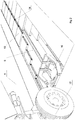
Fig. 2 shows a carriage in a guiding channel with a basket on which the wheel of the airplane rides; -
Fig. 3 shows the airport apron with a driving channel covered by pivotable plates; -
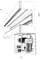
Fig. 4 shows a turning channel segment; -
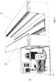
Fig. 5 shows a crossing channel segment; -
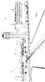
Fig. 6 shows a straight channel segment; -
Fig. 7 shows a straight channel segment; -
Fig. 8 shows a channel segment in cross-section; -
Fig. 9 shows an airport apron with open pivotable plates; -
Fig. 10 shows apart of an airport with crossing driving channels; and -
Fig. 11 shows a straight channel segment in cross-section. - As shown, in the embodiment of the invention illustrated in
Fig. 1 , an airport intended for taking-off and landingplanes 3 has anairport apron 4 where take-off/landing locations as well as parking locations forplanes 3 are defined. From such take-off/landing location of aplane 3 to a parking location theairplane 3 has to be transferred on theairport apron 4, and for thispurpose driving channels 1 are formed in theairport apron 4, as schematically presented inFig.1 . - In a driving
channel 1 formed in the airport apron 4 a transportingcarriage 2 is movable, which has acarriage actuator 15 and abasket 16, seated thereon, in which basket awheel 17 of anairplane 3 is positioned, as shown inFig. 2 ,Fig. 8 , andFig. 11 . In this embodiment on thebasket 16 of the transportingcarriage 2 the front wheel of theairplane 3 is positioned. Of course, the termfront wheel 17 of theairplane 3 also includes a front wheel assembly that may comprise more wheels, for example twin wheels. -
Fig. 2 shows schematically awheel 17 of anairplane 3 seated on abasket 16 of a transportingcarriage 2 located within adriving channel 1, which is not visible during movement of the transportingcarriage 2 within thedriving channel 1, since thedriving channel 1 is covered with apivotable plate 13. This plate may be pivoted upward, as shown inFig. 9 , or moved slidably aside so as to open thedriving channel 1, as shown inFig. 2 andFig. 8 . - The
driving channel 1, within which the transportingcarriage 2 is moved for transportingairplanes 3 from a take-off/landing location to a parking location, has to be routed in a way so as to enable movement of theairplane 3 between these locations. Therefore it has to cover a considerable part of theairport apron 4 which involves certain problems during laying the transportingchannel 1 on the existing airports and, at a lesser extent, on airports under construction. - In order to ensure efficient laying of the
driving channel 1, as well as enabling stepwise construction thereof, thedriving channel 1 is formed ofchannel segments 5 that in fact constitute subsequent lengths of the drivingchannel 1 being built.Channel segments 5 are shown inFig. 2 ,Fig. 4 ,Fig. 5 ,Fig. 6 ,Fig. 7 as well as inFig. 8 andFig. 11 . - Due to the fact that the
driving channel 1 may be routed along a path with turns, bifurcations, and crossings,channel segments 5 have to allow for such instances. This is why the system ofdriving channels 1 for acarriage 2 that transportsairplanes 3 on theairport apron 4 comprisesstraight segments 6, shown inFig. 6 andFig. 7 , crossing segments 7, shown inFig. 5 ,turning segments 9, shown inFig. 4 , and bifurcating segments. - The
driving channel 1 is built on theairport apron 4 by digging out a suitable trench in the ground for eachsubsequent channel segment 5 which may be, according to the particular need, astraight segment 6, a crossing segment at a point where different lengths of thedriving channel 1 are crossed, a bifurcating segment at a point where a possibility to select the further course of thedriving channel 1 is intended, and turningsegments 9 for which a varied curvature of the turn may be provided. - In the trench dug out in the airport apron 4 a channel segment is located in a manner that the top surface of the
channel segment 5 is flush with the surface of theairport apron 4. In this manner a levelled surface is obtained that has anarrow slot 14 only, created betweenpivotable plates 13 in their closed position. Theslot 14 of thechannel segment 5 does not obstruct the use of theairport apron 4 with thedriving channel 1 when compared to anairport apron 4 without such channel, and the airport may be also used in the same way as used before the driving channel was built. No problems are encountered when moving other vehicles on theairport apron 4. - As shown, in an embodiment of the invention illustrated in
Fig. 4 ,Fig. 5 ,Fig. 6 ,Fig. 7 ,Fig. 8 andFig. 11 , eachchannel segment 5, either astraight one 6, a crossing one 7, a turning one 9 or a bifurcating one, is provided with at least one drivingunit 10 that enables movement of the transportingcarriage 2 inside thechannel segment 5. Due to this concept eachchannel segment 5 is independent relative toother channel segments 5 with regard to movement of the transportingcarriage 2. -
Channel segments 5 may comprise more than one drivingunit 10, where for crossing segments 7 or bifurcating segments this is necessary, while for straight segments and turning segments it is not necessary. - Each driving
unit 10 comprises amotor 11 an atransmission gear 12. In the embodiments of the invention shown in the drawings in driving units 10 amotor 10 is used which is an electric motor andtransmission gear 12 is a belt transmission, but in other embodiments amotor 11 may be used which is a pneumatic motor, combustion motor or a hydraulic motor, and atransmission gear 12 which is a toothed gear, friction gear, tension gear or shaft gear. The system of drivingchannels 1 may also comprise a magnetic driving unit. - As shown in
Fig. 4 ,Fig. 5 ,Fig. 6 ,Fig. 7 ,Fig. 8 andFig. 11 , a drivingunit 10 is located in this embodiment of the invention in side cavities of thechannel segments 5 so that they do not obstruct the movement of the transportingcarriage 2 inside thechannel segment 5 of the drivingchannel 1. - It is clear that not all of the
channel segments 5 may be provided with theirown driving units 10 and the driving force is transmitted from achannel segment 5 provided with a drivingunit 10 to achannel segment 5 without a drivingunit 10, in a manner known in the art. - In this manner the transporting
carriage 2 is precisely and reliably guided in the drivingchannel 1. - The
airport apron 4 may be provided with several drivingchannels 1 of this kind in which a greater number of transportingcarriages 2 may be moved to transportairplanes 3 from a runway to a take-off location and vice versa. - A system of driving
channels 1 for acarriage 2 that transportsairplanes 3 on anairport apron 4 allows for fully automatically activating and stopping theindividual motors 11 and transmission gears 12 of drivingunits 10 inchannel segments 5 of drivingchannels 1 for transportingairplanes 3 and monitoring this process by the ground personnel of the airport. Cooperation with the pilot of the airplane during performing this is preferable but of course it is not indispensable. - It is clear that a person skilled in the art is able, without involving inventive activity, modify and improve in different ways the system of driving
channels 1 for acarriage 2 for transportingairplanes 3 on theairport apron 4 and the individual elements or assemblies thereof as presented in the non-limiting example, without departing from the contents of the patent claims.
Claims (13)
- A system of driving channels 1 for a carriage 2 that transports airplanes 3 on an airport apron 4, said carrier comprising an actuator 15 with a basket 16 set thereon, for wheels 17 of an airplane 3, and being movable in channels 1 arranged into taxi routes for airplanes 3 from a landing location to a parking location and from a parking location to a take-off location, characterized in that said channels (1) are formed by channel segments (5), said channel segments (5) being depressed in the airport apron (4) in a manner that their upper surface is flush with the surface of the airport apron (4).
- System of channels according to claim 1, characterized in that said channel segments (5) comprise straight channel, segments (6).
- System of channels according to claim 1, characterized in that said channel segments (5) comprise crossing channels segments (7).
- System of channels according to claim 1, characterized in that said channel segments (5) comprise bifurcating channel segments (8).
- System of channels according to claim 1, characterized in that said channel segments (5) comprise turning channel segments (9).
- System of channels, characterized in that it defines transporting routes (taxiways) and terminal transporting routes.
- System of channels according to claim 1, characterized in that each channel segment (6) is provided with at least one driving unit (10) comprising a motor (11) and a transmission gear (12) that put in motion a carriage (2) that transports the airplane (3), where said motor (11) may be an electric, pneumatic, hydraulic or combustion motor, and said transmission gear (12) may be a friction gear, toothed gear, tension gear, chain gear, belt or band transmission, shaft gear.
- System of channels according to claim 1, characterized in that said driving unit (10) comprises a magnetic derive.
- System of channels according to claim 1, characterized in that said channel segments (5), along their entire length, are provided at their upper surface with pivoting plates (13) of a segmented structure, openable when necessa.
- System of channels according to claim 9, characterized in that in their central part said pivoting plates (13) are provided with a slot (14) in which actuators (15), seated in said transporting carriage (2), are movable, said actuators carrying a basket (16) of said transporting carriage (2), in which the front wheel (17) of the transported airplane (3) is seated.
- System of channels according to claim 1, characterized in that said channel segments (5), along their entire length, are provided at their upper surface with slidable plates (18) of a segmented structure, openable when necessary.
- System of channels according to claim 11, characterized in that in their central part said slidable plates (18) are provided with a slot (14) in which actuators (15), seated in said transporting carriage (2), are movable, said actuators carrying a basket (16) of said transporting carriage (2), in which the front wheel (17) of the transported airplane (3) is seated.
- System of channels according to claim 1, characterized in that activating and stopping of the individual motors (11) and gears (12) of said driving units (10) in said channel segments (5) that transport airplanes (3) is controlled fully automatically and is monitored by the ground personnel of the airport, preferably in cooperation with the pilot of the airplane.
Applications Claiming Priority (1)
| Application Number | Priority Date | Filing Date | Title |
|---|---|---|---|
| PL414811A PL245327B1 (en) | 2015-11-16 | 2015-11-16 | A system of drive channels for a trolley transporting aircraft |
Publications (2)
| Publication Number | Publication Date |
|---|---|
| EP3168161A1 true EP3168161A1 (en) | 2017-05-17 |
| EP3168161B1 EP3168161B1 (en) | 2021-04-14 |
Family
ID=57539193
Family Applications (1)
| Application Number | Title | Priority Date | Filing Date |
|---|---|---|---|
| EP16460085.0A Active EP3168161B1 (en) | 2015-11-16 | 2016-11-15 | System of driving channels for a carriage for transporting airplanes on an airport apron |
Country Status (5)
| Country | Link |
|---|---|
| US (2) | US10486829B2 (en) |
| EP (1) | EP3168161B1 (en) |
| CN (1) | CN107010242B (en) |
| DK (1) | DK3168161T3 (en) |
| PL (1) | PL245327B1 (en) |
Families Citing this family (6)
| Publication number | Priority date | Publication date | Assignee | Title |
|---|---|---|---|---|
| FR3006990B1 (en) * | 2013-06-14 | 2015-07-17 | Eads Europ Aeronautic Defence | DEVICE FOR THE FLOOR MOVEMENT OF AIRCRAFT |
| US10059465B2 (en) | 2014-11-19 | 2018-08-28 | The Boeing Company | System to accelerate and decelerate aircraft for take-off and landing |
| US12459667B2 (en) * | 2015-11-16 | 2025-11-04 | Slawomir Malicki | System for transporting airplanes on an airport apron |
| DE102018109934A1 (en) * | 2018-04-25 | 2019-10-31 | Eisenmann Se | Treatment plant for the treatment of workpieces |
| CN109896036A (en) * | 2019-04-18 | 2019-06-18 | 太原科技大学 | flapper take-off device |
| KR20250080353A (en) * | 2023-11-28 | 2025-06-05 | 현대자동차주식회사 | Vertiport system including transfer unit using rail moving device |
Citations (8)
| Publication number | Priority date | Publication date | Assignee | Title |
|---|---|---|---|---|
| US2700937A (en) * | 1950-12-13 | 1955-02-01 | Whiting Corp | Apparatus for transporting aircraft |
| US3162404A (en) * | 1962-04-02 | 1964-12-22 | Superior Scaffold Co | Ground handling system for aircraft |
| WO1989008051A1 (en) * | 1988-02-25 | 1989-09-08 | Fmt International Trade Ab | System for automatic transportation of aircraft on the ground |
| JPH04317852A (en) * | 1991-04-17 | 1992-11-09 | Taisei Corp | Three-dimensional floor structure with built-in traction device |
| US6131854A (en) * | 1998-08-07 | 2000-10-17 | Lockheed Martin Corporation | Ground handling apparatus for unmanned tactical aircraft |
| WO2011096833A2 (en) * | 2010-02-05 | 2011-08-11 | Stavomir Malicki | System for transporting an airplane from a parking location to a takeoff location and from a landing location to a parking location |
| WO2013070102A2 (en) * | 2011-11-08 | 2013-05-16 | Malicki Slawomir | A carriage assembly for an airplane transporting system on an airport apron |
| CN105151312A (en) * | 2015-09-30 | 2015-12-16 | 罗元建 | Buried type automatic aircraft traction system and traction method |
-
2015
- 2015-11-16 PL PL414811A patent/PL245327B1/en unknown
-
2016
- 2016-11-15 DK DK16460085.0T patent/DK3168161T3/en active
- 2016-11-15 EP EP16460085.0A patent/EP3168161B1/en active Active
- 2016-11-15 CN CN201611005059.5A patent/CN107010242B/en active Active
- 2016-11-15 US US15/351,524 patent/US10486829B2/en active Active
-
2019
- 2019-11-05 US US16/674,518 patent/US11299291B2/en active Active
Patent Citations (9)
| Publication number | Priority date | Publication date | Assignee | Title |
|---|---|---|---|---|
| US2700937A (en) * | 1950-12-13 | 1955-02-01 | Whiting Corp | Apparatus for transporting aircraft |
| US3162404A (en) * | 1962-04-02 | 1964-12-22 | Superior Scaffold Co | Ground handling system for aircraft |
| WO1989008051A1 (en) * | 1988-02-25 | 1989-09-08 | Fmt International Trade Ab | System for automatic transportation of aircraft on the ground |
| JPH04317852A (en) * | 1991-04-17 | 1992-11-09 | Taisei Corp | Three-dimensional floor structure with built-in traction device |
| US6131854A (en) * | 1998-08-07 | 2000-10-17 | Lockheed Martin Corporation | Ground handling apparatus for unmanned tactical aircraft |
| WO2011096833A2 (en) * | 2010-02-05 | 2011-08-11 | Stavomir Malicki | System for transporting an airplane from a parking location to a takeoff location and from a landing location to a parking location |
| PL216097B1 (en) | 2010-02-05 | 2014-02-28 | Slawomir Malicki | Set for moving aircraft from the stop site to the start or from landing site to the stop site |
| WO2013070102A2 (en) * | 2011-11-08 | 2013-05-16 | Malicki Slawomir | A carriage assembly for an airplane transporting system on an airport apron |
| CN105151312A (en) * | 2015-09-30 | 2015-12-16 | 罗元建 | Buried type automatic aircraft traction system and traction method |
Also Published As
| Publication number | Publication date |
|---|---|
| US20200079527A1 (en) | 2020-03-12 |
| US10486829B2 (en) | 2019-11-26 |
| CN107010242B (en) | 2021-04-09 |
| DK3168161T3 (en) | 2021-07-05 |
| PL414811A1 (en) | 2017-05-22 |
| EP3168161B1 (en) | 2021-04-14 |
| CN107010242A (en) | 2017-08-04 |
| US11299291B2 (en) | 2022-04-12 |
| US20170137149A1 (en) | 2017-05-18 |
| PL245327B1 (en) | 2024-07-01 |
Similar Documents
| Publication | Publication Date | Title |
|---|---|---|
| EP3168161B1 (en) | System of driving channels for a carriage for transporting airplanes on an airport apron | |
| US9771148B2 (en) | Airport terminal aircraft gate traffic management system and method | |
| EP2948375B1 (en) | Aircraft thrust, assembly, and methods | |
| CN102264600A (en) | Method of moving machinery for operating aircraft within an airport area | |
| DE102005004717A1 (en) | Platform-based runway system for aircraft, has mobile platform that is adjusted and moved according to movement and actual flight phase of starting/landing aircraft , accelerating aircraft while starting, and decelerating landing aircraft | |
| DE4102271C2 (en) | Device for starting and landing aircraft without a chassis | |
| EP2776320B1 (en) | A carriage assembly for an airplane transporting system on an airport apron | |
| EP2534050B1 (en) | System for transporting an airplane from a parking location to a takeoff location and from a landing location to a parking location | |
| EP3737596B1 (en) | Cable transportation system comprising a station and method for operating such cable transportation system | |
| US20150221224A1 (en) | Permanent wireless communications system for an aircraft equipped with a wheel drive system | |
| US10839715B2 (en) | Training system and simulation method for ground travel in aircraft equipped with non-engine drive means | |
| US20250171162A1 (en) | Vertiport system including transfer unit using rail moving device | |
| HK1241826A1 (en) | A system of driving channels for an airplane-transporting carriage on the airport apron | |
| HK1241826B (en) | A system of driving channels for an airplane-transporting carriage on the airport apron | |
| AU2011213369B8 (en) | System for transporting an airplane from a parking location to a takeoff location and from a landing location to a parking location | |
| JPH07115678B2 (en) | Underground airport system | |
| JP2024004429A (en) | Airfield for vertical take-off and landing aircraft and transportation method for vertical take-off and landing aircraft |
Legal Events
| Date | Code | Title | Description |
|---|---|---|---|
| PUAI | Public reference made under article 153(3) epc to a published international application that has entered the european phase |
Free format text: ORIGINAL CODE: 0009012 |
|
| STAA | Information on the status of an ep patent application or granted ep patent |
Free format text: STATUS: REQUEST FOR EXAMINATION WAS MADE |
|
| 17P | Request for examination filed |
Effective date: 20161130 |
|
| AK | Designated contracting states |
Kind code of ref document: A1 Designated state(s): AL AT BE BG CH CY CZ DE DK EE ES FI FR GB GR HR HU IE IS IT LI LT LU LV MC MK MT NL NO PL PT RO RS SE SI SK SM TR |
|
| AX | Request for extension of the european patent |
Extension state: BA ME |
|
| STAA | Information on the status of an ep patent application or granted ep patent |
Free format text: STATUS: EXAMINATION IS IN PROGRESS |
|
| 17Q | First examination report despatched |
Effective date: 20190507 |
|
| GRAP | Despatch of communication of intention to grant a patent |
Free format text: ORIGINAL CODE: EPIDOSNIGR1 |
|
| STAA | Information on the status of an ep patent application or granted ep patent |
Free format text: STATUS: GRANT OF PATENT IS INTENDED |
|
| INTG | Intention to grant announced |
Effective date: 20201106 |
|
| GRAS | Grant fee paid |
Free format text: ORIGINAL CODE: EPIDOSNIGR3 |
|
| GRAA | (expected) grant |
Free format text: ORIGINAL CODE: 0009210 |
|
| STAA | Information on the status of an ep patent application or granted ep patent |
Free format text: STATUS: THE PATENT HAS BEEN GRANTED |
|
| AK | Designated contracting states |
Kind code of ref document: B1 Designated state(s): AL AT BE BG CH CY CZ DE DK EE ES FI FR GB GR HR HU IE IS IT LI LT LU LV MC MK MT NL NO PL PT RO RS SE SI SK SM TR |
|
| REG | Reference to a national code |
Ref country code: GB Ref legal event code: FG4D |
|
| REG | Reference to a national code |
Ref country code: CH Ref legal event code: EP |
|
| REG | Reference to a national code |
Ref country code: DE Ref legal event code: R096 Ref document number: 602016056018 Country of ref document: DE |
|
| REG | Reference to a national code |
Ref country code: IE Ref legal event code: FG4D |
|
| REG | Reference to a national code |
Ref country code: AT Ref legal event code: REF Ref document number: 1382163 Country of ref document: AT Kind code of ref document: T Effective date: 20210515 |
|
| REG | Reference to a national code |
Ref country code: NL Ref legal event code: FP |
|
| REG | Reference to a national code |
Ref country code: DK Ref legal event code: T3 Effective date: 20210701 |
|
| REG | Reference to a national code |
Ref country code: LT Ref legal event code: MG9D |
|
| PG25 | Lapsed in a contracting state [announced via postgrant information from national office to epo] |
Ref country code: BG Free format text: LAPSE BECAUSE OF FAILURE TO SUBMIT A TRANSLATION OF THE DESCRIPTION OR TO PAY THE FEE WITHIN THE PRESCRIBED TIME-LIMIT Effective date: 20210714 Ref country code: HR Free format text: LAPSE BECAUSE OF FAILURE TO SUBMIT A TRANSLATION OF THE DESCRIPTION OR TO PAY THE FEE WITHIN THE PRESCRIBED TIME-LIMIT Effective date: 20210414 Ref country code: LT Free format text: LAPSE BECAUSE OF FAILURE TO SUBMIT A TRANSLATION OF THE DESCRIPTION OR TO PAY THE FEE WITHIN THE PRESCRIBED TIME-LIMIT Effective date: 20210414 Ref country code: FI Free format text: LAPSE BECAUSE OF FAILURE TO SUBMIT A TRANSLATION OF THE DESCRIPTION OR TO PAY THE FEE WITHIN THE PRESCRIBED TIME-LIMIT Effective date: 20210414 |
|
| PG25 | Lapsed in a contracting state [announced via postgrant information from national office to epo] |
Ref country code: IS Free format text: LAPSE BECAUSE OF FAILURE TO SUBMIT A TRANSLATION OF THE DESCRIPTION OR TO PAY THE FEE WITHIN THE PRESCRIBED TIME-LIMIT Effective date: 20210814 Ref country code: GR Free format text: LAPSE BECAUSE OF FAILURE TO SUBMIT A TRANSLATION OF THE DESCRIPTION OR TO PAY THE FEE WITHIN THE PRESCRIBED TIME-LIMIT Effective date: 20210715 Ref country code: LV Free format text: LAPSE BECAUSE OF FAILURE TO SUBMIT A TRANSLATION OF THE DESCRIPTION OR TO PAY THE FEE WITHIN THE PRESCRIBED TIME-LIMIT Effective date: 20210414 Ref country code: RS Free format text: LAPSE BECAUSE OF FAILURE TO SUBMIT A TRANSLATION OF THE DESCRIPTION OR TO PAY THE FEE WITHIN THE PRESCRIBED TIME-LIMIT Effective date: 20210414 Ref country code: SE Free format text: LAPSE BECAUSE OF FAILURE TO SUBMIT A TRANSLATION OF THE DESCRIPTION OR TO PAY THE FEE WITHIN THE PRESCRIBED TIME-LIMIT Effective date: 20210414 Ref country code: PL Free format text: LAPSE BECAUSE OF FAILURE TO SUBMIT A TRANSLATION OF THE DESCRIPTION OR TO PAY THE FEE WITHIN THE PRESCRIBED TIME-LIMIT Effective date: 20210414 Ref country code: PT Free format text: LAPSE BECAUSE OF FAILURE TO SUBMIT A TRANSLATION OF THE DESCRIPTION OR TO PAY THE FEE WITHIN THE PRESCRIBED TIME-LIMIT Effective date: 20210816 Ref country code: NO Free format text: LAPSE BECAUSE OF FAILURE TO SUBMIT A TRANSLATION OF THE DESCRIPTION OR TO PAY THE FEE WITHIN THE PRESCRIBED TIME-LIMIT Effective date: 20210714 |
|
| REG | Reference to a national code |
Ref country code: AT Ref legal event code: UEP Ref document number: 1382163 Country of ref document: AT Kind code of ref document: T Effective date: 20210414 |
|
| REG | Reference to a national code |
Ref country code: DE Ref legal event code: R097 Ref document number: 602016056018 Country of ref document: DE |
|
| PG25 | Lapsed in a contracting state [announced via postgrant information from national office to epo] |
Ref country code: SM Free format text: LAPSE BECAUSE OF FAILURE TO SUBMIT A TRANSLATION OF THE DESCRIPTION OR TO PAY THE FEE WITHIN THE PRESCRIBED TIME-LIMIT Effective date: 20210414 Ref country code: SK Free format text: LAPSE BECAUSE OF FAILURE TO SUBMIT A TRANSLATION OF THE DESCRIPTION OR TO PAY THE FEE WITHIN THE PRESCRIBED TIME-LIMIT Effective date: 20210414 Ref country code: EE Free format text: LAPSE BECAUSE OF FAILURE TO SUBMIT A TRANSLATION OF THE DESCRIPTION OR TO PAY THE FEE WITHIN THE PRESCRIBED TIME-LIMIT Effective date: 20210414 Ref country code: CZ Free format text: LAPSE BECAUSE OF FAILURE TO SUBMIT A TRANSLATION OF THE DESCRIPTION OR TO PAY THE FEE WITHIN THE PRESCRIBED TIME-LIMIT Effective date: 20210414 Ref country code: RO Free format text: LAPSE BECAUSE OF FAILURE TO SUBMIT A TRANSLATION OF THE DESCRIPTION OR TO PAY THE FEE WITHIN THE PRESCRIBED TIME-LIMIT Effective date: 20210414 Ref country code: ES Free format text: LAPSE BECAUSE OF FAILURE TO SUBMIT A TRANSLATION OF THE DESCRIPTION OR TO PAY THE FEE WITHIN THE PRESCRIBED TIME-LIMIT Effective date: 20210413 |
|
| PLBE | No opposition filed within time limit |
Free format text: ORIGINAL CODE: 0009261 |
|
| STAA | Information on the status of an ep patent application or granted ep patent |
Free format text: STATUS: NO OPPOSITION FILED WITHIN TIME LIMIT |
|
| 26N | No opposition filed |
Effective date: 20220117 |
|
| PG25 | Lapsed in a contracting state [announced via postgrant information from national office to epo] |
Ref country code: IS Free format text: LAPSE BECAUSE OF FAILURE TO SUBMIT A TRANSLATION OF THE DESCRIPTION OR TO PAY THE FEE WITHIN THE PRESCRIBED TIME-LIMIT Effective date: 20210814 Ref country code: AL Free format text: LAPSE BECAUSE OF FAILURE TO SUBMIT A TRANSLATION OF THE DESCRIPTION OR TO PAY THE FEE WITHIN THE PRESCRIBED TIME-LIMIT Effective date: 20210414 |
|
| PG25 | Lapsed in a contracting state [announced via postgrant information from national office to epo] |
Ref country code: MC Free format text: LAPSE BECAUSE OF FAILURE TO SUBMIT A TRANSLATION OF THE DESCRIPTION OR TO PAY THE FEE WITHIN THE PRESCRIBED TIME-LIMIT Effective date: 20210414 |
|
| PG25 | Lapsed in a contracting state [announced via postgrant information from national office to epo] |
Ref country code: LU Free format text: LAPSE BECAUSE OF NON-PAYMENT OF DUE FEES Effective date: 20211115 Ref country code: BE Free format text: LAPSE BECAUSE OF NON-PAYMENT OF DUE FEES Effective date: 20211130 |
|
| REG | Reference to a national code |
Ref country code: BE Ref legal event code: MM Effective date: 20211130 |
|
| PG25 | Lapsed in a contracting state [announced via postgrant information from national office to epo] |
Ref country code: IE Free format text: LAPSE BECAUSE OF NON-PAYMENT OF DUE FEES Effective date: 20211115 |
|
| PG25 | Lapsed in a contracting state [announced via postgrant information from national office to epo] |
Ref country code: HU Free format text: LAPSE BECAUSE OF FAILURE TO SUBMIT A TRANSLATION OF THE DESCRIPTION OR TO PAY THE FEE WITHIN THE PRESCRIBED TIME-LIMIT; INVALID AB INITIO Effective date: 20161115 |
|
| PG25 | Lapsed in a contracting state [announced via postgrant information from national office to epo] |
Ref country code: CY Free format text: LAPSE BECAUSE OF FAILURE TO SUBMIT A TRANSLATION OF THE DESCRIPTION OR TO PAY THE FEE WITHIN THE PRESCRIBED TIME-LIMIT Effective date: 20210414 |
|
| PG25 | Lapsed in a contracting state [announced via postgrant information from national office to epo] |
Ref country code: MK Free format text: LAPSE BECAUSE OF FAILURE TO SUBMIT A TRANSLATION OF THE DESCRIPTION OR TO PAY THE FEE WITHIN THE PRESCRIBED TIME-LIMIT Effective date: 20210414 |
|
| PG25 | Lapsed in a contracting state [announced via postgrant information from national office to epo] |
Ref country code: TR Free format text: LAPSE BECAUSE OF FAILURE TO SUBMIT A TRANSLATION OF THE DESCRIPTION OR TO PAY THE FEE WITHIN THE PRESCRIBED TIME-LIMIT Effective date: 20210414 |
|
| PG25 | Lapsed in a contracting state [announced via postgrant information from national office to epo] |
Ref country code: MT Free format text: LAPSE BECAUSE OF FAILURE TO SUBMIT A TRANSLATION OF THE DESCRIPTION OR TO PAY THE FEE WITHIN THE PRESCRIBED TIME-LIMIT Effective date: 20210414 |
|
| REG | Reference to a national code |
Ref country code: CH Ref legal event code: U11 Free format text: ST27 STATUS EVENT CODE: U-0-0-U10-U11 (AS PROVIDED BY THE NATIONAL OFFICE) Effective date: 20251201 |
|
| PGFP | Annual fee paid to national office [announced via postgrant information from national office to epo] |
Ref country code: NL Payment date: 20251127 Year of fee payment: 10 |
|
| PGFP | Annual fee paid to national office [announced via postgrant information from national office to epo] |
Ref country code: DE Payment date: 20251124 Year of fee payment: 10 |
|
| PGFP | Annual fee paid to national office [announced via postgrant information from national office to epo] |
Ref country code: GB Payment date: 20251126 Year of fee payment: 10 |
|
| PGFP | Annual fee paid to national office [announced via postgrant information from national office to epo] |
Ref country code: AT Payment date: 20251126 Year of fee payment: 10 |
|
| PGFP | Annual fee paid to national office [announced via postgrant information from national office to epo] |
Ref country code: IT Payment date: 20251120 Year of fee payment: 10 Ref country code: DK Payment date: 20251125 Year of fee payment: 10 |
|
| PGFP | Annual fee paid to national office [announced via postgrant information from national office to epo] |
Ref country code: FR Payment date: 20251128 Year of fee payment: 10 |
|
| PGFP | Annual fee paid to national office [announced via postgrant information from national office to epo] |
Ref country code: CH Payment date: 20251201 Year of fee payment: 10 |