EP3168074A1 - Vehicle radiator apparatus - Google Patents
Vehicle radiator apparatus Download PDFInfo
- Publication number
- EP3168074A1 EP3168074A1 EP16197348.2A EP16197348A EP3168074A1 EP 3168074 A1 EP3168074 A1 EP 3168074A1 EP 16197348 A EP16197348 A EP 16197348A EP 3168074 A1 EP3168074 A1 EP 3168074A1
- Authority
- EP
- European Patent Office
- Prior art keywords
- radiator
- vehicle
- main body
- portions
- shock absorbing
- Prior art date
- Legal status (The legal status is an assumption and is not a legal conclusion. Google has not performed a legal analysis and makes no representation as to the accuracy of the status listed.)
- Granted
Links
- 230000035939 shock Effects 0.000 claims description 43
- 230000002787 reinforcement Effects 0.000 description 36
- 239000004918 carbon fiber reinforced polymer Substances 0.000 description 4
- 238000001816 cooling Methods 0.000 description 4
- 239000000463 material Substances 0.000 description 4
- 239000000498 cooling water Substances 0.000 description 3
- 230000002093 peripheral effect Effects 0.000 description 3
- 229920003002 synthetic resin Polymers 0.000 description 3
- 239000000057 synthetic resin Substances 0.000 description 3
- 229910000838 Al alloy Inorganic materials 0.000 description 2
- 239000000956 alloy Substances 0.000 description 2
- 238000005452 bending Methods 0.000 description 2
- 239000000470 constituent Substances 0.000 description 2
- 229910052751 metal Inorganic materials 0.000 description 2
- 239000002184 metal Substances 0.000 description 2
- 239000007769 metal material Substances 0.000 description 2
- 230000008878 coupling Effects 0.000 description 1
- 238000010168 coupling process Methods 0.000 description 1
- 238000005859 coupling reaction Methods 0.000 description 1
- 238000000034 method Methods 0.000 description 1
Images




Classifications
-
- B—PERFORMING OPERATIONS; TRANSPORTING
- B60—VEHICLES IN GENERAL
- B60K—ARRANGEMENT OR MOUNTING OF PROPULSION UNITS OR OF TRANSMISSIONS IN VEHICLES; ARRANGEMENT OR MOUNTING OF PLURAL DIVERSE PRIME-MOVERS IN VEHICLES; AUXILIARY DRIVES FOR VEHICLES; INSTRUMENTATION OR DASHBOARDS FOR VEHICLES; ARRANGEMENTS IN CONNECTION WITH COOLING, AIR INTAKE, GAS EXHAUST OR FUEL SUPPLY OF PROPULSION UNITS IN VEHICLES
- B60K11/00—Arrangement in connection with cooling of propulsion units
- B60K11/02—Arrangement in connection with cooling of propulsion units with liquid cooling
- B60K11/04—Arrangement or mounting of radiators, radiator shutters, or radiator blinds
-
- B—PERFORMING OPERATIONS; TRANSPORTING
- B60—VEHICLES IN GENERAL
- B60K—ARRANGEMENT OR MOUNTING OF PROPULSION UNITS OR OF TRANSMISSIONS IN VEHICLES; ARRANGEMENT OR MOUNTING OF PLURAL DIVERSE PRIME-MOVERS IN VEHICLES; AUXILIARY DRIVES FOR VEHICLES; INSTRUMENTATION OR DASHBOARDS FOR VEHICLES; ARRANGEMENTS IN CONNECTION WITH COOLING, AIR INTAKE, GAS EXHAUST OR FUEL SUPPLY OF PROPULSION UNITS IN VEHICLES
- B60K11/00—Arrangement in connection with cooling of propulsion units
- B60K11/08—Air inlets for cooling; Shutters or blinds therefor
- B60K11/085—Air inlets for cooling; Shutters or blinds therefor with adjustable shutters or blinds
-
- Y—GENERAL TAGGING OF NEW TECHNOLOGICAL DEVELOPMENTS; GENERAL TAGGING OF CROSS-SECTIONAL TECHNOLOGIES SPANNING OVER SEVERAL SECTIONS OF THE IPC; TECHNICAL SUBJECTS COVERED BY FORMER USPC CROSS-REFERENCE ART COLLECTIONS [XRACs] AND DIGESTS
- Y02—TECHNOLOGIES OR APPLICATIONS FOR MITIGATION OR ADAPTATION AGAINST CLIMATE CHANGE
- Y02T—CLIMATE CHANGE MITIGATION TECHNOLOGIES RELATED TO TRANSPORTATION
- Y02T10/00—Road transport of goods or passengers
- Y02T10/80—Technologies aiming to reduce greenhouse gasses emissions common to all road transportation technologies
- Y02T10/88—Optimized components or subsystems, e.g. lighting, actively controlled glasses
Definitions
- This disclosure relates to a radiator apparatus for a vehicle.
- JP 2011-201439A discloses a vehicle radiator apparatus.
- the vehicle radiator apparatus includes a radiator main body, and a grill shutter unit that adjusts the amount of air flowing toward the radiator main body.
- the grill shutter unit includes a shutter member configured to open or close a grill opening that is an air intake port, a framework-like frame that supports the shutter member, and a drive device that drives the shutter member.
- an air guiding plate is installed between the radiator main body and the grill shutter unit to guide air introduced from the grill opening to the radiator main body.
- the air guiding plate is attached to the bottom surface of the grill shutter unit to support the grill shutter unit.
- the frame of the grill shutter unit is formed in a rectangular framework shape, and the grill opening (the open area of the air intake port) is substantially narrowed by the thickness of the framework.
- the cooling performance of the vehicle radiator apparatus may be deteriorated.
- a vehicle radiator apparatus includes: a radiator main body; a grill shutter unit configured to adjust the amount of air that is introduced from an opening formed in front of the radiator main body and flows toward the radiator main body; and an air guiding plate provided to extend in a longitudinal direction below the radiator main body and the grill shutter unit so as to guide the air introduced from the opening to the radiator main body.
- the grill shutter unit includes a shutter member configured to open or close the opening of a vehicle and a shutter support member configured to support the shutter member.
- the shutter support member includes a pair of left and right side frame portions and an upper frame portion that interconnects the upper ends of the side frame portions, and is opened downward. The lower ends of the side frame portions of the grill shutter unit are assembled and attached to the upper surface portion of the air guiding plate.
- the shutter support member of the grill shutter unit is opened downward. That is, in the grill shutter unit known in the related art, the lower frame portion is omitted and the lower ends of the side frame portions are directly assembled and attached to the air guiding plate.
- the grill opening may be enlarged by the lower frame portion, compared to the grill shutter unit known in the related art. Accordingly, the cooling performance of the vehicle radiator apparatus may be improved. In addition, the number of parts may be reduced, compared to the vehicle radiator apparatus known in the related art.
- the vehicle radiator apparatus further includes a radiator support member configured to support the radiator main body, the radiator support member includes a pair of left and right vertical column portions, and a horizontal column portion that interconnects the upper ends of the vertical column portions, and is opened downward, and the lower end of the radiator main body and the lower ends of the vertical column portions of the radiator support member are assembled and attached to a back end of the air guiding plate.
- the radiator support member is also opened downward like the shutter support member, and the lower ends of the vertical column portions are directly assembled and attached to the air guiding plate. Accordingly, the number of parts may be reduced, compared to a case where the lower frame portion of the radiator support member is provided as a separate member.
- the air guiding plate includes a shock absorbing member configured to absorb shock generated at the time of collision of the vehicle.
- the shock generated at the time of collision of the vehicle is mainly absorbed by the shock absorbing member connected to a bumper reinforcement.
- the shock absorbing member according to this disclosure functions as an auxiliary member. Accordingly, the vehicle, to which the vehicle radiator apparatus according to this disclosure is applied, may absorb more shock.
- the shock absorbing member is provided to extend in the vehicle longitudinal direction, and the air guiding plate includes a holding portion configured to hold the shock absorbing member. According to this configuration, at the time of collision, it is possible to suppress the shock absorbing member from being separated and to suppress the middle portion of the shock absorbing member from being bent so that the shock absorbing member may exhibit a sufficient shock absorbing performance.
- Another feature of the aspect of this disclosure resides in that the lower ends of the side frame portions of the grill shutter unit are assembled and attached to the shock absorbing member. According to this configuration, the grill shutter unit may be stably maintained.
- the vehicle includes a pair of left and right side members S, S that extend in the vehicle longitudinal direction.
- Shock absorbing members CB, CB are respectively attached to the front end surfaces of the side members S, S.
- the shock absorbing members CB, CB are formed in a cylindrical shape that extends in the vehicle longitudinal direction.
- a bumper reinforcement BR extending in the vehicle width direction is attached to the front end surfaces of the shock absorbing members CB, CB.
- the shock absorbing members CB, CB When an object collides with the front end of the vehicle, the shock absorbing members CB, CB are deformed in the manner of being compressed in the vehicle longitudinal direction, thereby absorbing shock applied due to collision.
- the vehicle radiator apparatus 1 is located in the space surrounded by the bumper reinforcement BR, the shock absorbing members CB, CB, and the side members S, S.
- the vehicle radiator apparatus 1 includes a radiator main body 10, a radiator support member 20, a grill shutter unit 30, and an air guiding plate 40.
- the structure of the radiator main body 10 is the same as a radiator main body well-known in the art. That is, the radiator main body 10 is connected to a cooling water flow path installed in an engine, and air-cools cooling water of which the temperature is raised by passing through the engine. That is, the radiator main body 10 includes fins 11 configured to radiate heat of the cooling water. In addition, upwardly and downwardly protruding bush portions 12 are formed respectively on the upper end surface and lower end surface of the radiator main body 10.
- the radiator support member 20 includes a main body 21 and a reinforcement unit 22.
- the main body 21 includes a pair of left and right vertical column portions 211, 212 that are provided to extend in the vehicle height direction, and a horizontal column portion 213 that interconnects the upper ends of the vertical column portions 211, 212.
- the vertical column portions 211, 212 and the horizontal column portion 213 are integrally formed using a synthetic resin material.
- the vertical column portions 211, 212 are provided to extend along the opposite left and right edges of the radiator main body 10.
- the vertical column portions 211, 212 are formed in a box shape that is opened forward, and plural reinforcement ribs are provided therein.
- the horizontal column portion 213 is provided to extend in the vehicle width direction. That is, the horizontal column portion 213 is provided to extend along the upper edge of the radiator main body 10. As illustrated in Fig. 4 , the cross section of the horizontal column portion 213, which is perpendicular to the vehicle width direction, has a step shape.
- the horizontal column portion 213 includes a base portion 213a, a recessed portion 213b, and a protruding portion 213c.
- the base portion 213a is formed in a plate shape that extends in the vehicle width direction and is perpendicular to the vehicle height direction.
- the plate thickness of the front end portion of the base portion 213a is larger than that of the back end portion.
- the recessed portion 213b is connected to the lower end portion in the front side end of the base portion 213a, and is located ahead and below the base portion 213a.
- the recessed portion 213b is opened backward.
- the recessed portion 213b is located at the front side of the upper edge of the radiator main body 10 in a state where the radiator main body 10 is supported by the radiator support member 20 (see Figs. 5 and 6 ).
- the reinforcement unit 22 to be described below is inserted into and fixed to the recessed portion 213b.
- the protruding portion 213c is connected to the front end portion of the recessed portion 213b, and is located ahead and below the recessed portion 213b.
- a hood lock HL configured to lock a front end of a vehicle hood H is assembled and attached to the front surface of the protruding portion 213c (see Figs. 1 and 5 ).
- Through-holes TH 213a are formed in the left and right ends of the base portion 213a to penetrate the base portion 213a in the vehicle height direction (see Figs. 3 and 6 ).
- the through-holes TH 213a correspond to the bush portions 12.
- two through-holes TH 213b are formed in each of the left and right ends of the recessed portion 213b to inwardly penetrate the recessed portion 213b from the upper surface thereof (see Fig. 3 ).
- a bolt is inserted into each through-hole TH 213b to fix the reinforcement unit 22 to be described subsequently.
- the reinforcement unit 22 includes a tubular portion 221 and a reinforcement sheet 222 (see Fig. 3 ).
- the tubular portion 221 is formed in an angled tube shape that extends in the vehicle width direction.
- the tubular portion 221 is longer than the horizontal column portion 213 of the radiator support member 20. That is, the tubular portion 221 protrudes leftward and rightward from the main body 21 in a state of being fixed to the recessed portion 213b.
- the central portion of the tubular portion 221 in the longitudinal direction is parallel to the vehicle width direction. Portions are bent backward that are middle portions in the longitudinal direction of the tubular portion 221 and are respectively located at the left end and the right end of the main body 21 in a state where the reinforcement unit 22 is fixed to the recessed portion 213b.
- Each of left and right protrusions is formed to extend obliquely backward and linearly that are the end portions of the tubular portion 221 and respectively protrude from the main body 21.
- Through-holes TH 221 are formed in each of the tip end portions of the protrusions (i.e., left and right end portions) to penetrate the protrusions in the vehicle height direction.
- a bolt is inserted into each of the through-holes TH 221 to fix the vehicle radiator apparatus 1 to the vehicle main body.
- female screws FT 221 are formed in the upper wall portion of the central portion of the tubular portion 221 in the longitudinal direction (i.e., the portion formed to be parallel to the vehicle width direction). The female screws FT 221 correspond to the through-holes TH 213b .
- the tubular portion 221 is formed in the following manner. First, a linearly extending angled tube is formed by extruding a metal material (e.g., an aluminum alloy material). Then, middle portions of the angled cylinder in the longitudinal direction (i.e., portions respectively located at the left end and the right end of the main body 21) are bent backward. Subsequently, the through-hole TH 221 and the female screw FT 221 are formed. In this way, the tubular portion 221 is formed.
- a metal material e.g., an aluminum alloy material
- the reinforcement sheet 222 is formed of carbon fiber reinforced plastic (CFRP).
- CFRP carbon fiber reinforced plastic
- the reinforcement sheet 222 is formed in a sheet shape that extends in the vehicle width direction and is perpendicular to the vehicle height direction.
- the reinforcement sheet 222 is bonded to a lower surface of the central portion of the tubular portion 221 in the vehicle width direction.
- the reinforcement unit 22 is fixed to the recessed portion 213b in the following manner. First, the reinforcement unit 22 is inserted into the recessed portion 213b. Then, a bolt is inserted into each of the through-holes TH 213b and the tip end of the bolt is fastened to each of the female screws FT 221 . In this way, the reinforcement unit 22 is fixed to the recessed portion 213b.
- the grill shutter unit 30 is located in the grill opening of the vehicle in a state where the vehicle radiator apparatus 1 is assembled and attached to the vehicle so as to adjust the amount of air introduced into the engine room from the grill opening and flowing toward the radiator main body 10.
- the grill shutter unit 30 includes plural (e.g., four (4)) shutter members 31, a shutter support member 32 to support the shutter members 31, and a drive unit 33 to drive the shutter members 31.
- Each of the shutter members 31 includes a shaft portion 311 and a plate-shaped portion 312.
- the shaft portion 311 is formed in a bar shape that extends in the vehicle width direction.
- the plate-shaped portion 312 is formed in a plate shape that extends in the vehicle width direction.
- the shaft portion 311 is formed in the center of the plate-shaped portion 312 in the width direction (i.e., the direction perpendicular to the vehicle width direction and the plate thickness direction).
- the shutter support member 32 includes a pair of left and right side frame portions 321, 322 that extends in the vehicle height direction, an upper frame portion 323 that interconnects the upper ends of the side frame portions 321, 322, and a reinforcement portion 324 that supports the center of the upper frame portion 323.
- the side frame portion 321 is formed in a box shape that is opened leftward. That is, the side frame portion 321 includes a bottom wall portion 321 a that is perpendicular to the vehicle width direction, and a peripheral wall portion 321 b that surrounds the periphery of the bottom wall portion 321 a.
- the side frame portion 321 includes a bracket portion 321 c provided to extend leftward from the bottom wall portion 321 a and is formed in a plate shape that is perpendicular to the vehicle height direction.
- a through-hole TH 321c is formed in the bracket portion 321 c to penetrate the bracket portion 321 c in the vehicle height direction.
- the side frame portion 322 has a shape bilaterally symmetrical with the side frame portion 321. That is, like the side frame portion 321, the side frame portion 322 includes a bottom wall portion 322a, a peripheral wall portion 322b, and a bracket portion 322c.
- a through-hole TH 322c is formed in the bracket portion 322c.
- the upper frame portion 323 is formed in a plate shape that extends in the vehicle width direction and is perpendicular to the vehicle height direction.
- the reinforcement portion 324 is formed in a column shape that extends downward from the center of the upper frame portion 323 in the vehicle width direction.
- the side frame portions 321, 322, the upper frame portion 323, and the reinforcement portion 324 are integrally formed using a synthetic resin material.
- the drive unit 33 includes a drive shaft that is configured to rotate about the center axis extending in the vehicle width direction.
- the drive unit 33 includes a motor (e.g., a stepping motor configured to adjust the rotating angle of the drive shaft.
- the drive unit 33 is assembled and attached to a right side surface of the bottom wall portion 322a of the side frame portion 322.
- Two through-holes TH 32 are formed in each of the side frame portions 321, 322 and the reinforcement portion 324 to penetrate each of the side frame portions 321, 322 and the reinforcement portion 324 in the vehicle width direction.
- the two through-holes TH 32 are spaced apart from each other in the vehicle height direction.
- the shaft portion 311 of each shutter member 31 is inserted into the through-holes TH 32 . Thereby, the shutter member 31 is supported to rotate about the center axis of the through-holes TH 32 .
- Two shutter members 31, 31 are supported between the side frame portion 321 and the reinforcement portion 324, and the other two shutter members 31, 31 are supported between the side frame portion 322 and the reinforcement portion 324.
- the shaft portions 311, 311 of the shutter members 31, 31 at the right side are connected to the drive shaft of the drive unit 33.
- the shaft portions 311, 311 of the shutter members 31, 31 at the left side are connected to the shaft portions 311, 311 of the shutter members 31, 31 at the right side via a coupling member (not illustrated).
- a coupling member not illustrated.
- each shutter member 31 rotates about the center axis of the shaft portion 311.
- all the shutter members 31 rotate in the same direction.
- the amount of air introduced from the grill opening into the engine room may be adjusted by adjusting the rotation angle of the shutter member 31.
- the air guiding plate 40 includes a plate-shaped portion 41 and shock absorbing members 42, 42.
- the plate-shaped portion 41 includes a base end portion 411, a main body 412, a connection portion 413, and holding portions 414, 414 (see Figs. 5 and 6 ).
- the base end portion 411 is formed in a plate shape that extends in the vehicle width direction from a back end of the plate-shaped portion 41 and is perpendicular to the vehicle height direction.
- Through-holes TH 411 are formed in the base end portion 411 to penetrate the base end portion 411 in the vehicle height direction (see Fig. 6 ).
- the through-holes TH 411 correspond to the bush portions 12.
- the main body 412 is located ahead and above the base end portion 411.
- the main body 412 is formed in a plate shape that extends in the vehicle width direction and the vehicle longitudinal direction.
- the front end of the main body 412 is formed in a plate shape that is perpendicular to the vehicle height direction. A portion of the main body 412 from the center to the back end in the vehicle longitudinal direction is bent upward.
- a through-hole TH 412 is formed in the front end of the main body 412 to penetrate the main body 412 in the vehicle height direction.
- the through-hole TH 412 is located in the center in the vehicle width direction.
- plural reinforcement ribs are formed on the lower surface of the main body 412.
- connection portion 413 is formed in a plate shape that extends in the vehicle width direction and is perpendicular to the vehicle longitudinal direction.
- the upper end of the connection portion 413 is connected to the back end of the main body 412, and the lower end of the connection portion 413 is connected to the front end of the base end portion 411.
- the holding portions 414, 414 are respectively connected to the left and right ends of the main body 412 (see Fig. 8 ).
- the holding portions 414 are formed in a box shape that extends in the vehicle longitudinal direction and is opened downward.
- Four through-holes TH 414 are formed in a wall portion at the upper side of the holding portion 414 (i.e., an upper bottom portion) so as to penetrate in the vehicle height direction.
- the four through-holes TH 414 are spaced apart from one another in the vehicle longitudinal direction.
- the shock absorbing member 42 is formed in an angled tube shape that extends in the vehicle longitudinal direction.
- the shock absorbing member 42 is formed by extruding, for example, a metal material (an aluminum alloy material).
- Four female screws FT 42 are formed in a wall portion at the upper side of the shock absorbing member 42 to correspond to four through-holes TH 414 , respectively.
- the shock absorbing members 42, 42 are inserted into the holding portions 414, 414 from the lower side of the holding portions 414, 414.
- the shock absorbing members 42, 42 are fixed to the holding members 414, 414.
- bolts are fastened to only two female screws FT 42 at the back side, among the four female screws FT 42 of the shock absorbing member 42 so that only the back side portion of the shock absorbing member 42 is fixed to the holding portion 414. Then, as described subsequently, in a process of assembling the vehicle radiator apparatus 1, bolts are fastened to the other two female screws FT 42 so that the front side portion of the shock absorbing member 42 is fixed to the holding portion 414.
- the sequence of assembling the vehicle radiator apparatus 1 will be described (see Fig. 2 ).
- the bush portions 12 at the lower side of the radiator main body 10 are inserted into the through-holes TH 411 of the air guiding plate 40 so that the radiator main body 10 is placed on the upper surface of the base end portion 411 of the air guiding plate 40.
- the radiator support member 20 is lowered from above the radiator main body 10 so that the bush portions 12 at the upper side of the radiator main body 10 are inserted into the through-holes TH 213a of the radiator support member 20.
- the lower ends of the vertical column portions 211, 212 are assembled and attached to the base end portion 411.
- the height of the back end of the main body 412 of the air guiding plate 40 coincides with the height of lower ends of the fins 11 of the radiator main body 10.
- the lower end of the reinforcement portion 34 of the grill shutter unit 30 is inserted into the through-hole TH 412 of the air guiding plate 40, and the bracket portions 321 c and 322c are placed on the upper surfaces of the holding portions 414, 414.
- the through-holes TH 321c , TH 322c in the bracket portions 321 c, 322c correspond to two through-holes TH 414 in the front side of each of the holding portions 414, 414 and two female screws FT 42 in the front side of each of the shock absorbing members 42, 42.
- Bolts are inserted into the through-holes TH 321c , TH3 22c and the through-holes TH 414 and are fastened to the female screws FT 42 .
- the grill shutter unit 30 is fixed to the air guiding plate 40, and the front side portion of the shock absorbing member 42 is fixed to the air guiding plate 40.
- the vehicle radiator apparatus 1 is assembled.
- the vehicle radiator apparatus 1 is inserted into the engine room from the lower side of the engine room and is assembled and attached to the vehicle main body. Specifically, opposite ends of the reinforcement unit 22, the vertical column portions 211, 212, and the holding portions 414, 414 are fastened to members (e.g., side members) that constitute the framework of the vehicle. In addition, an under-plate UP is assembled and attached to the lower side of the vehicle radiator apparatus 1 (see Fig. 1 ).
- the main body 21 of the radiator support member 20 is formed of a synthetic resin material, and the horizontal column portion 213 thereof is reinforced by the metal reinforcement unit 22. Accordingly, the weight may be reduced and high rigidity may be maintained, compared to a case where the entire radiator support member is formed of a metal.
- the reinforcement unit 22 (the tubular portion 221) is formed in the tube shape that extends in the vehicle width direction, torsional rigidity is high, compared to a horizontal column portion formed in a groove shape that is opened downward, as in the conventional radiator support member.
- the reinforcement sheet 222 formed of carbon fiber reinforced plastic is bonded to the lower surface of the central portion in the vehicle width direction.
- the reinforcement unit 22 is located in front of the upper end of the radiator main body 10. Accordingly, the dimension of the vehicle radiator apparatus 1 in the vehicle height direction may be reduced, compared to a case where the reinforcement unit 22 is located above the radiator main body 10.
- the shutter support member 32 of the grill shutter unit 30 is opened downward. That is, the lower frame portion in the conventional grill shutter unit is omitted, and the lower ends of the side frame portions 321, 322 are directly assembled and attached to the air guiding plate 40. Accordingly, the grill opening may be substantially enlarged by the lower frame portion, compared to the conventional grill shutter unit. Accordingly, the cooling performance of the radiator apparatus may be improved. In addition, the number of parts may be reduced, compared to the conventional grill shutter unit.
- the radiator support member 20 is also opened downward so that the lower ends of the vertical column portions 211, 212 are directly assembled and attached to the air guiding plate 40. Accordingly, the number of parts may be reduced, compared to a case where the lower frame portion of the radiator support member 20 is installed as a separate member.
- the air guiding plate 40 includes the shock absorbing member 42, more shock may be absorbed, compared to a vehicle having only the shock absorbing member CB.
- the shock absorbing member 42 is accommodated and fixed in the holding portion 414 formed in a box shape.
- the bending of the shock absorbing member 42 in the direction of the center axis thereof is suppressed.
- the shock absorbing member 42 is deformed in the manner of being compressed in the direction of the center axis thereof. Accordingly, shock is efficiently absorbed.
- the lower ends of the side frame portions 321, 322 of the grill shutter unit 30 are assembled and attached to the shock absorbing members 42, 42 that have relatively high rigidity. Accordingly, the grill shutter unit 30 may be stably maintained.
- the reinforcement sheet 222 is bonded to the tubular portion 221 in the embodiment, the tubular portion 221 and the reinforcement sheet 222 may be integrally formed (e.g., insert-molded).
- the reinforcement sheet 222 not only the wall portion at the lower side of the central portion of the tubular portion 221 in the vehicle width direction, but also a portion over a wider range may be reinforced by the reinforcement sheet 222.
- the entire peripheral portion of the central portion of the tubular portion 221 in the vehicle width direction may be reinforced by the reinforcement sheet 222.
- the reinforcement sheet 222 is not limited to carbon fiber reinforced plastic, and may be formed using any other material.
Landscapes
- Engineering & Computer Science (AREA)
- Chemical & Material Sciences (AREA)
- Combustion & Propulsion (AREA)
- Transportation (AREA)
- Mechanical Engineering (AREA)
- Cooling, Air Intake And Gas Exhaust, And Fuel Tank Arrangements In Propulsion Units (AREA)
- Air-Conditioning For Vehicles (AREA)
Abstract
Description
- This disclosure relates to a radiator apparatus for a vehicle.
-
JP 2011-201439A - In addition, there is also a case in which an air guiding plate is installed between the radiator main body and the grill shutter unit to guide air introduced from the grill opening to the radiator main body. The air guiding plate is attached to the bottom surface of the grill shutter unit to support the grill shutter unit.
- In the vehicle radiator apparatus known in the related art, the frame of the grill shutter unit is formed in a rectangular framework shape, and the grill opening (the open area of the air intake port) is substantially narrowed by the thickness of the framework. Thus, the cooling performance of the vehicle radiator apparatus may be deteriorated.
- Thus, a need exists for a vehicle radiator apparatus that is improved in cooling performance. Meanwhile, in the description of each constituent requirement of this disclosure, a reference numeral of a corresponding part of an embodiment is described in a bracket in order to facilitate the understanding of this disclosure. However, each constituent requirement of this disclosure should not be interpreted as being limited to the configuration of the corresponding part indicated by the reference numeral of the embodiment.
- A feature of an aspect of this disclosure resides in that a vehicle radiator apparatus includes: a radiator main body; a grill shutter unit configured to adjust the amount of air that is introduced from an opening formed in front of the radiator main body and flows toward the radiator main body; and an air guiding plate provided to extend in a longitudinal direction below the radiator main body and the grill shutter unit so as to guide the air introduced from the opening to the radiator main body. The grill shutter unit includes a shutter member configured to open or close the opening of a vehicle and a shutter support member configured to support the shutter member. The shutter support member includes a pair of left and right side frame portions and an upper frame portion that interconnects the upper ends of the side frame portions, and is opened downward. The lower ends of the side frame portions of the grill shutter unit are assembled and attached to the upper surface portion of the air guiding plate.
- According to the aspect of this disclosure, the shutter support member of the grill shutter unit is opened downward. That is, in the grill shutter unit known in the related art, the lower frame portion is omitted and the lower ends of the side frame portions are directly assembled and attached to the air guiding plate. Thus, the grill opening may be enlarged by the lower frame portion, compared to the grill shutter unit known in the related art. Accordingly, the cooling performance of the vehicle radiator apparatus may be improved. In addition, the number of parts may be reduced, compared to the vehicle radiator apparatus known in the related art.
- Another feature of the aspect of this disclosure resides in that the vehicle radiator apparatus further includes a radiator support member configured to support the radiator main body, the radiator support member includes a pair of left and right vertical column portions, and a horizontal column portion that interconnects the upper ends of the vertical column portions, and is opened downward, and the lower end of the radiator main body and the lower ends of the vertical column portions of the radiator support member are assembled and attached to a back end of the air guiding plate.
- According to this configuration, the radiator support member is also opened downward like the shutter support member, and the lower ends of the vertical column portions are directly assembled and attached to the air guiding plate. Accordingly, the number of parts may be reduced, compared to a case where the lower frame portion of the radiator support member is provided as a separate member.
- Another feature of the aspect of this disclosure resides in that the air guiding plate includes a shock absorbing member configured to absorb shock generated at the time of collision of the vehicle.
- The shock generated at the time of collision of the vehicle is mainly absorbed by the shock absorbing member connected to a bumper reinforcement. The shock absorbing member according to this disclosure functions as an auxiliary member. Accordingly, the vehicle, to which the vehicle radiator apparatus according to this disclosure is applied, may absorb more shock.
- Another feature of the aspect of this disclosure resides in that the shock absorbing member is provided to extend in the vehicle longitudinal direction, and the air guiding plate includes a holding portion configured to hold the shock absorbing member. According to this configuration, at the time of collision, it is possible to suppress the shock absorbing member from being separated and to suppress the middle portion of the shock absorbing member from being bent so that the shock absorbing member may exhibit a sufficient shock absorbing performance.
- Another feature of the aspect of this disclosure resides in that the lower ends of the side frame portions of the grill shutter unit are assembled and attached to the shock absorbing member. According to this configuration, the grill shutter unit may be stably maintained.
- The foregoing and additional features and characteristics of this disclosure will become more apparent from the following detailed description considered with the reference to the accompanying drawings, wherein:
-
Fig. 1 is a schematic view illustrating the structure of a front portion of a vehicle, to which a vehicle radiator apparatus according to this disclosure is applied; -
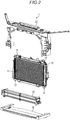
Fig. 2 is an exploded perspective view of the vehicle radiator apparatus ofFig. 1 ; -
Fig. 3 is an exploded perspective view of a radiator support member; -
Fig. 4 is a sectional view illustrating a cross section, perpendicular to the vehicle width direction, of a horizontal column portion of the radiator support member; -
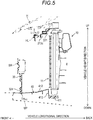
Fig. 5 is a sectional view illustrating a cross section, perpendicular to the vehicle width direction, a central portion in the vehicle width direction in the front portion of the vehicle, to which the vehicle radiator apparatus according to this disclosure is applied; -
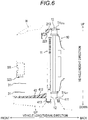
Fig. 6 is a sectional view illustrating a cross section, perpendicular to the vehicle width direction, of a left end portion of a radiator main body in the front portion of the vehicle, to which the vehicle radiator apparatus according to this disclosure is applied; -
Fig. 7 is a perspective view of a grill shutter unit; and -
Fig. 8 is a perspective view of an air guiding plate. - Hereinafter, a vehicle radiator apparatus 1 according to an embodiment disclosed here will be described. First, the structure of the front end portion of a vehicle, to which the vehicle radiator apparatus 1 is applied, will be described briefly. As illustrated in
Fig. 1 , the vehicle includes a pair of left and right side members S, S that extend in the vehicle longitudinal direction. Shock absorbing members CB, CB are respectively attached to the front end surfaces of the side members S, S. The shock absorbing members CB, CB are formed in a cylindrical shape that extends in the vehicle longitudinal direction. A bumper reinforcement BR extending in the vehicle width direction is attached to the front end surfaces of the shock absorbing members CB, CB. When an object collides with the front end of the vehicle, the shock absorbing members CB, CB are deformed in the manner of being compressed in the vehicle longitudinal direction, thereby absorbing shock applied due to collision. The vehicle radiator apparatus 1 is located in the space surrounded by the bumper reinforcement BR, the shock absorbing members CB, CB, and the side members S, S. - Next, the vehicle radiator apparatus 1 will be described in detail. As illustrated in
Fig. 2 , the vehicle radiator apparatus 1 includes a radiatormain body 10, aradiator support member 20, agrill shutter unit 30, and anair guiding plate 40. - The structure of the radiator
main body 10 is the same as a radiator main body well-known in the art. That is, the radiatormain body 10 is connected to a cooling water flow path installed in an engine, and air-cools cooling water of which the temperature is raised by passing through the engine. That is, the radiatormain body 10 includes fins 11 configured to radiate heat of the cooling water. In addition, upwardly and downwardly protrudingbush portions 12 are formed respectively on the upper end surface and lower end surface of the radiatormain body 10. - As illustrated in
Fig. 3 , theradiator support member 20 includes amain body 21 and areinforcement unit 22. Themain body 21 includes a pair of left and rightvertical column portions horizontal column portion 213 that interconnects the upper ends of thevertical column portions vertical column portions horizontal column portion 213 are integrally formed using a synthetic resin material. - The
vertical column portions main body 10. Thevertical column portions - The
horizontal column portion 213 is provided to extend in the vehicle width direction. That is, thehorizontal column portion 213 is provided to extend along the upper edge of the radiatormain body 10. As illustrated inFig. 4 , the cross section of thehorizontal column portion 213, which is perpendicular to the vehicle width direction, has a step shape. Thehorizontal column portion 213 includes abase portion 213a, a recessedportion 213b, and a protrudingportion 213c. - The
base portion 213a is formed in a plate shape that extends in the vehicle width direction and is perpendicular to the vehicle height direction. The plate thickness of the front end portion of thebase portion 213a is larger than that of the back end portion. - The recessed
portion 213b is connected to the lower end portion in the front side end of thebase portion 213a, and is located ahead and below thebase portion 213a. The recessedportion 213b is opened backward. The recessedportion 213b is located at the front side of the upper edge of the radiatormain body 10 in a state where the radiatormain body 10 is supported by the radiator support member 20 (seeFigs. 5 and6 ). Thereinforcement unit 22 to be described below is inserted into and fixed to the recessedportion 213b. - The protruding
portion 213c is connected to the front end portion of the recessedportion 213b, and is located ahead and below the recessedportion 213b. A hood lock HL configured to lock a front end of a vehicle hood H is assembled and attached to the front surface of the protrudingportion 213c (seeFigs. 1 and5 ). Through-holes TH213a are formed in the left and right ends of thebase portion 213a to penetrate thebase portion 213a in the vehicle height direction (seeFigs. 3 and6 ). The through-holes TH213a correspond to thebush portions 12. In addition, two through-holes TH213b are formed in each of the left and right ends of the recessedportion 213b to inwardly penetrate the recessedportion 213b from the upper surface thereof (seeFig. 3 ). A bolt is inserted into each through-hole TH213b to fix thereinforcement unit 22 to be described subsequently. - The
reinforcement unit 22 includes atubular portion 221 and a reinforcement sheet 222 (seeFig. 3 ). Thetubular portion 221 is formed in an angled tube shape that extends in the vehicle width direction. Thetubular portion 221 is longer than thehorizontal column portion 213 of theradiator support member 20. That is, thetubular portion 221 protrudes leftward and rightward from themain body 21 in a state of being fixed to the recessedportion 213b. The central portion of thetubular portion 221 in the longitudinal direction is parallel to the vehicle width direction. Portions are bent backward that are middle portions in the longitudinal direction of thetubular portion 221 and are respectively located at the left end and the right end of themain body 21 in a state where thereinforcement unit 22 is fixed to the recessedportion 213b. Each of left and right protrusions is formed to extend obliquely backward and linearly that are the end portions of thetubular portion 221 and respectively protrude from themain body 21. Through-holes TH221 are formed in each of the tip end portions of the protrusions (i.e., left and right end portions) to penetrate the protrusions in the vehicle height direction. A bolt is inserted into each of the through-holes TH221 to fix the vehicle radiator apparatus 1 to the vehicle main body. In addition, female screws FT221 are formed in the upper wall portion of the central portion of thetubular portion 221 in the longitudinal direction (i.e., the portion formed to be parallel to the vehicle width direction). The female screws FT221 correspond to the through-holes TH213b. - The
tubular portion 221 is formed in the following manner. First, a linearly extending angled tube is formed by extruding a metal material (e.g., an aluminum alloy material). Then, middle portions of the angled cylinder in the longitudinal direction (i.e., portions respectively located at the left end and the right end of the main body 21) are bent backward. Subsequently, the through-hole TH221 and the female screw FT221 are formed. In this way, thetubular portion 221 is formed. - The
reinforcement sheet 222 is formed of carbon fiber reinforced plastic (CFRP). Thereinforcement sheet 222 is formed in a sheet shape that extends in the vehicle width direction and is perpendicular to the vehicle height direction. Thereinforcement sheet 222 is bonded to a lower surface of the central portion of thetubular portion 221 in the vehicle width direction. - The
reinforcement unit 22 is fixed to the recessedportion 213b in the following manner. First, thereinforcement unit 22 is inserted into the recessedportion 213b. Then, a bolt is inserted into each of the through-holes TH213b and the tip end of the bolt is fastened to each of the female screws FT221. In this way, thereinforcement unit 22 is fixed to the recessedportion 213b. - The
grill shutter unit 30 is located in the grill opening of the vehicle in a state where the vehicle radiator apparatus 1 is assembled and attached to the vehicle so as to adjust the amount of air introduced into the engine room from the grill opening and flowing toward the radiatormain body 10. As illustrated inFig. 7 , thegrill shutter unit 30 includes plural (e.g., four (4))shutter members 31, a shutter support member 32 to support theshutter members 31, and adrive unit 33 to drive theshutter members 31. - Each of the
shutter members 31 includes ashaft portion 311 and a plate-shapedportion 312. Theshaft portion 311 is formed in a bar shape that extends in the vehicle width direction. The plate-shapedportion 312 is formed in a plate shape that extends in the vehicle width direction. Theshaft portion 311 is formed in the center of the plate-shapedportion 312 in the width direction (i.e., the direction perpendicular to the vehicle width direction and the plate thickness direction). - The shutter support member 32 includes a pair of left and right
side frame portions upper frame portion 323 that interconnects the upper ends of theside frame portions reinforcement portion 324 that supports the center of theupper frame portion 323. Theside frame portion 321 is formed in a box shape that is opened leftward. That is, theside frame portion 321 includes abottom wall portion 321 a that is perpendicular to the vehicle width direction, and aperipheral wall portion 321 b that surrounds the periphery of thebottom wall portion 321 a. Moreover, theside frame portion 321 includes abracket portion 321 c provided to extend leftward from thebottom wall portion 321 a and is formed in a plate shape that is perpendicular to the vehicle height direction. A through-hole TH321c is formed in thebracket portion 321 c to penetrate thebracket portion 321 c in the vehicle height direction. Theside frame portion 322 has a shape bilaterally symmetrical with theside frame portion 321. That is, like theside frame portion 321, theside frame portion 322 includes abottom wall portion 322a, aperipheral wall portion 322b, and abracket portion 322c. In addition, a through-hole TH322c is formed in thebracket portion 322c. Theupper frame portion 323 is formed in a plate shape that extends in the vehicle width direction and is perpendicular to the vehicle height direction. Thereinforcement portion 324 is formed in a column shape that extends downward from the center of theupper frame portion 323 in the vehicle width direction. Theside frame portions upper frame portion 323, and thereinforcement portion 324 are integrally formed using a synthetic resin material. - The
drive unit 33 includes a drive shaft that is configured to rotate about the center axis extending in the vehicle width direction. Thedrive unit 33 includes a motor (e.g., a stepping motor configured to adjust the rotating angle of the drive shaft. Thedrive unit 33 is assembled and attached to a right side surface of thebottom wall portion 322a of theside frame portion 322. - Two through-holes TH32 are formed in each of the
side frame portions reinforcement portion 324 to penetrate each of theside frame portions reinforcement portion 324 in the vehicle width direction. The two through-holes TH32 are spaced apart from each other in the vehicle height direction. Theshaft portion 311 of eachshutter member 31 is inserted into the through-holes TH32. Thereby, theshutter member 31 is supported to rotate about the center axis of the through-holes TH32. Twoshutter members side frame portion 321 and thereinforcement portion 324, and the other twoshutter members side frame portion 322 and thereinforcement portion 324. Theshaft portions shutter members drive unit 33. Theshaft portions shutter members shaft portions shutter members drive unit 33 rotates, eachshutter member 31 rotates about the center axis of theshaft portion 311. In addition, all theshutter members 31 rotate in the same direction. The amount of air introduced from the grill opening into the engine room may be adjusted by adjusting the rotation angle of theshutter member 31. - As illustrated in
Fig. 8 , theair guiding plate 40 includes a plate-shapedportion 41 andshock absorbing members portion 41 includes abase end portion 411, amain body 412, aconnection portion 413, and holdingportions 414, 414 (seeFigs. 5 and6 ). - The
base end portion 411 is formed in a plate shape that extends in the vehicle width direction from a back end of the plate-shapedportion 41 and is perpendicular to the vehicle height direction. Through-holes TH411 are formed in thebase end portion 411 to penetrate thebase end portion 411 in the vehicle height direction (seeFig. 6 ). The through-holes TH411 correspond to thebush portions 12. - The
main body 412 is located ahead and above thebase end portion 411. Themain body 412 is formed in a plate shape that extends in the vehicle width direction and the vehicle longitudinal direction. The front end of themain body 412 is formed in a plate shape that is perpendicular to the vehicle height direction. A portion of themain body 412 from the center to the back end in the vehicle longitudinal direction is bent upward. In addition, a through-hole TH412 is formed in the front end of themain body 412 to penetrate themain body 412 in the vehicle height direction. The through-hole TH412 is located in the center in the vehicle width direction. In addition, plural reinforcement ribs are formed on the lower surface of themain body 412. - The
connection portion 413 is formed in a plate shape that extends in the vehicle width direction and is perpendicular to the vehicle longitudinal direction. The upper end of theconnection portion 413 is connected to the back end of themain body 412, and the lower end of theconnection portion 413 is connected to the front end of thebase end portion 411. - The holding
portions Fig. 8 ). The holdingportions 414 are formed in a box shape that extends in the vehicle longitudinal direction and is opened downward. Four through-holes TH414 are formed in a wall portion at the upper side of the holding portion 414 (i.e., an upper bottom portion) so as to penetrate in the vehicle height direction. The four through-holes TH414 are spaced apart from one another in the vehicle longitudinal direction. - The
shock absorbing member 42 is formed in an angled tube shape that extends in the vehicle longitudinal direction. Theshock absorbing member 42 is formed by extruding, for example, a metal material (an aluminum alloy material). Four female screws FT42 are formed in a wall portion at the upper side of theshock absorbing member 42 to correspond to four through-holes TH414, respectively. Theshock absorbing members portions portions shock absorbing members members shock absorbing member 42 so that only the back side portion of theshock absorbing member 42 is fixed to the holdingportion 414. Then, as described subsequently, in a process of assembling the vehicle radiator apparatus 1, bolts are fastened to the other two female screws FT42 so that the front side portion of theshock absorbing member 42 is fixed to the holdingportion 414. - Subsequently, the sequence of assembling the vehicle radiator apparatus 1 will be described (see
Fig. 2 ). First, thebush portions 12 at the lower side of the radiatormain body 10 are inserted into the through-holes TH411 of theair guiding plate 40 so that the radiatormain body 10 is placed on the upper surface of thebase end portion 411 of theair guiding plate 40. Subsequently, theradiator support member 20 is lowered from above the radiatormain body 10 so that thebush portions 12 at the upper side of the radiatormain body 10 are inserted into the through-holes TH213a of theradiator support member 20. Then, the lower ends of thevertical column portions base end portion 411. In this state, the height of the back end of themain body 412 of theair guiding plate 40 coincides with the height of lower ends of thefins 11 of the radiatormain body 10. After passing through thegrill shutter unit 30, air flows along themain body 412. That is, air introduced into the engine room flows toward thefins 11. Subsequently, the lower end of the reinforcement portion 34 of thegrill shutter unit 30 is inserted into the through-hole TH412 of theair guiding plate 40, and thebracket portions portions bracket portions portions shock absorbing members grill shutter unit 30 is fixed to theair guiding plate 40, and the front side portion of theshock absorbing member 42 is fixed to theair guiding plate 40. In the above-described manner, the vehicle radiator apparatus 1 is assembled. - The vehicle radiator apparatus 1 is inserted into the engine room from the lower side of the engine room and is assembled and attached to the vehicle main body. Specifically, opposite ends of the
reinforcement unit 22, thevertical column portions portions Fig. 1 ). - According to the vehicle radiator apparatus 1 configured as described above, the
main body 21 of theradiator support member 20 is formed of a synthetic resin material, and thehorizontal column portion 213 thereof is reinforced by themetal reinforcement unit 22. Accordingly, the weight may be reduced and high rigidity may be maintained, compared to a case where the entire radiator support member is formed of a metal. In particular, because the reinforcement unit 22 (the tubular portion 221) is formed in the tube shape that extends in the vehicle width direction, torsional rigidity is high, compared to a horizontal column portion formed in a groove shape that is opened downward, as in the conventional radiator support member. In addition, thereinforcement sheet 222 formed of carbon fiber reinforced plastic is bonded to the lower surface of the central portion in the vehicle width direction. Accordingly, rigidity (bending rigidity) against an external force that downwardly presses the central portion of thehorizontal column portion 213 in the vehicle width direction is high. Accordingly, the deformation of thehorizontal column portion 213 may be suppressed even if a relatively large load is applied to thehorizontal column portion 213 via the hood lock HL when the hood H is opened or closed. In addition, in the vehicle radiator apparatus 1, thereinforcement unit 22 is located in front of the upper end of the radiatormain body 10. Accordingly, the dimension of the vehicle radiator apparatus 1 in the vehicle height direction may be reduced, compared to a case where thereinforcement unit 22 is located above the radiatormain body 10. - In addition, the shutter support member 32 of the
grill shutter unit 30 is opened downward. That is, the lower frame portion in the conventional grill shutter unit is omitted, and the lower ends of theside frame portions air guiding plate 40. Accordingly, the grill opening may be substantially enlarged by the lower frame portion, compared to the conventional grill shutter unit. Accordingly, the cooling performance of the radiator apparatus may be improved. In addition, the number of parts may be reduced, compared to the conventional grill shutter unit. - In addition, as in the shutter support member 32, the
radiator support member 20 is also opened downward so that the lower ends of thevertical column portions air guiding plate 40. Accordingly, the number of parts may be reduced, compared to a case where the lower frame portion of theradiator support member 20 is installed as a separate member. - In addition, because the
air guiding plate 40 includes theshock absorbing member 42, more shock may be absorbed, compared to a vehicle having only the shock absorbing member CB. In addition, theshock absorbing member 42 is accommodated and fixed in the holdingportion 414 formed in a box shape. Thus, the bending of theshock absorbing member 42 in the direction of the center axis thereof is suppressed. In other words, at the time of collision, theshock absorbing member 42 is deformed in the manner of being compressed in the direction of the center axis thereof. Accordingly, shock is efficiently absorbed. - In addition, the lower ends of the
side frame portions grill shutter unit 30 are assembled and attached to theshock absorbing members grill shutter unit 30 may be stably maintained. - Moreover, the implementation of this disclosure is not limited to the embodiment, and may be changed in various ways so long as it does not deviate from the object disclosed here.
- For example, although the
reinforcement sheet 222 is bonded to thetubular portion 221 in the embodiment, thetubular portion 221 and thereinforcement sheet 222 may be integrally formed (e.g., insert-molded). In addition, not only the wall portion at the lower side of the central portion of thetubular portion 221 in the vehicle width direction, but also a portion over a wider range may be reinforced by thereinforcement sheet 222. For example, the entire peripheral portion of the central portion of thetubular portion 221 in the vehicle width direction may be reinforced by thereinforcement sheet 222. In addition, thereinforcement sheet 222 is not limited to carbon fiber reinforced plastic, and may be formed using any other material. - The principles, preferred embodiment and mode of operation of the present invention have been described in the foregoing specification. However, the invention which is intended to be protected is not to be construed as limited to the particular embodiments disclosed. Further, the embodiments described herein are to be regarded as illustrative rather than restrictive. Variations and changes may be made by others, and equivalents employed, without departing from the spirit of the present invention. Accordingly, it is expressly intended that all such variations, changes and equivalents which fall within the spirit and scope of the present invention as defined in the claims, be embraced thereby.
Claims (5)
- A vehicle radiator apparatus (1) comprising:a radiator main body (10);a grill shutter unit (30) configured to adjust the amount of air that is introduced from an opening formed in front of the radiator main body and flows toward the radiator main body; andan air guiding plate (40) provided to extend in a longitudinal direction below the radiator main body and the grill shutter unit so as to guide the air introduced from the opening to the radiator main body,wherein the grill shutter unit includes:a shutter member (31) configured to open or close the opening of a vehicle; anda shutter support member (32) configured to support the shutter member, and including a pair of left and right side frame portions (321, 322) and an upper frame portion (323) that interconnects upper ends of the side frame portions, the shutter support member being opened downward, andwherein lower ends of the side frame portions of the grill shutter unit are assembled and attached to an upper surface portion of the air guiding plate.
- The vehicle radiator apparatus according to claim 1, further comprising a radiator support member (20) configured to support the radiator main body,
wherein the radiator support member includes a pair of left and right vertical column portions (211, 212), and a horizontal column portion (213) that interconnects upper ends of the vertical column portions, and is open downward, and
wherein lower ends of the radiator main body and lower ends of the vertical column portions of the radiator support member are assembled and attached to a back end of the air guiding plate. - The vehicle radiator apparatus according to claim 1 or 2, wherein the air guiding plate includes a shock absorbing member (42) configured to absorb shock generated upon collision of a vehicle.
- The vehicle radiator apparatus according to claim 3, wherein the shock absorbing member is provided to extend in a vehicle longitudinal direction, and
wherein the air guiding plate includes a holding portion (414) configured to hold the shock absorbing member. - The vehicle radiator apparatus according to claim 4, wherein the lower ends of the side frame portions of the grill shutter unit are assembled and attached to the shock absorbing member.
Applications Claiming Priority (1)
| Application Number | Priority Date | Filing Date | Title |
|---|---|---|---|
| JP2015219396A JP6618774B2 (en) | 2015-11-09 | 2015-11-09 | Radiator device for vehicle |
Publications (2)
| Publication Number | Publication Date |
|---|---|
| EP3168074A1 true EP3168074A1 (en) | 2017-05-17 |
| EP3168074B1 EP3168074B1 (en) | 2018-05-09 |
Family
ID=57233353
Family Applications (1)
| Application Number | Title | Priority Date | Filing Date |
|---|---|---|---|
| EP16197348.2A Not-in-force EP3168074B1 (en) | 2015-11-09 | 2016-11-04 | Vehicle radiator apparatus |
Country Status (3)
| Country | Link |
|---|---|
| US (1) | US9950610B2 (en) |
| EP (1) | EP3168074B1 (en) |
| JP (1) | JP6618774B2 (en) |
Cited By (1)
| Publication number | Priority date | Publication date | Assignee | Title |
|---|---|---|---|---|
| FR3135953A1 (en) * | 2022-05-30 | 2023-12-01 | Psa Automobiles Sa | AIR CONVEYING DEVICE BETWEEN AN AIR INLET GRILLE AND EQUIPMENT OF A LAND VEHICLE |
Families Citing this family (8)
| Publication number | Priority date | Publication date | Assignee | Title |
|---|---|---|---|---|
| US10661650B2 (en) | 2016-07-22 | 2020-05-26 | Nimer Ibrahim Shiheiber | Radiator system |
| DE102017200967A1 (en) * | 2017-01-20 | 2018-07-26 | Röchling Automotive SE & Co. KG | Air damper device with damper adjustment on the basis of a determined risk of collision |
| US11512623B2 (en) | 2017-07-17 | 2022-11-29 | Kohler Co. | Apparatus for controlling cooling airflow to an intenral combustion engine, and engines and methods utilizing the same |
| FR3071470B1 (en) * | 2017-09-27 | 2020-10-02 | Valeo Systemes Thermiques | AIR FLOW REGULATION DEVICE FOR A MOTOR VEHICLE FRONT PANEL MODULE |
| JP6879175B2 (en) * | 2017-11-14 | 2021-06-02 | トヨタ自動車株式会社 | Grill shutter device |
| CN109532467B (en) * | 2018-12-20 | 2024-01-12 | 天津巴泰克汽车装备有限公司 | New energy electric automobile radiator |
| US12043107B2 (en) * | 2022-03-16 | 2024-07-23 | Honda Motor Co., Ltd. | Air intake assembly for vehicle, front end assembly of vehicle, and method |
| US20250060177A1 (en) * | 2023-08-15 | 2025-02-20 | Valeo Systemes Thermiques | Stone guard |
Citations (5)
| Publication number | Priority date | Publication date | Assignee | Title |
|---|---|---|---|---|
| JP2011201439A (en) | 2010-03-25 | 2011-10-13 | Aisin Seiki Co Ltd | Movable grille shutter for vehicle |
| US20130192801A1 (en) * | 2012-01-10 | 2013-08-01 | U.S. Farathane Corporation | Reconfigurable front and upper one piece baffles for directing incoming air from a vehicle front fascia to a radiator cooling module |
| WO2014036432A1 (en) * | 2012-08-31 | 2014-03-06 | Magna International Inc. | Active grille shutter multi part modular frame |
| DE102013222489A1 (en) * | 2012-11-12 | 2014-05-15 | GM Global Technology Operations, LLC (n.d. Ges. d. Staates Delaware) | Front panel or grille support structure and aerodynamic shutter assembly |
| FR3013302A1 (en) * | 2013-11-19 | 2015-05-22 | Renault Sa | MONOPIECE AIR GUIDE FOR FRONT PANEL OF MOTOR VEHICLE AND VEHICLE THUS EQUIPPED |
Family Cites Families (15)
| Publication number | Priority date | Publication date | Assignee | Title |
|---|---|---|---|---|
| US3888531A (en) * | 1973-03-21 | 1975-06-10 | Straza Enterprises Ltd | Frangible shock absorbing bumper |
| US6003912A (en) * | 1996-04-09 | 1999-12-21 | Chrysler Corporation | Bi-metal vehicle bumper structure |
| DE10112424A1 (en) * | 2001-03-15 | 2002-09-26 | Daimler Chrysler Ag | Front of a motor vehicle comprises an air guiding part arranged below a bumper and interacting in the event of a front collision with the bumper covering and reinforcing this in a region positioned in front of the bumper |
| FR2830229B1 (en) * | 2001-09-28 | 2004-01-23 | Valeo Equip Electr Moteur | FRONT PANEL OF MOTOR VEHICLE INCLUDING A BUMPER BEAM |
| US7497289B2 (en) * | 2005-09-22 | 2009-03-03 | Hyundai Mobis Co., Ltd. | Structure of carrier |
| JP2008049935A (en) * | 2006-08-28 | 2008-03-06 | Mazda Motor Corp | Body front structure |
| JP4661941B2 (en) * | 2008-11-06 | 2011-03-30 | トヨタ自動車株式会社 | Automobile and control method thereof |
| JP5424022B2 (en) * | 2009-03-25 | 2014-02-26 | アイシン精機株式会社 | Movable fin drive unit |
| EP2423024B1 (en) * | 2009-04-24 | 2014-06-25 | Honda Motor Co., Ltd. | Air guide duct structure for vehicle |
| DE102009032592A1 (en) * | 2009-07-10 | 2011-01-13 | GM Global Technology Operations, Inc., Detroit | Front part for motor vehicle body, has bumper and mobile closure element that is arranged in fresh air duct for modulating flow rate of fresh air duct, and bumper carrier provided to form wall for fresh air duct |
| US8308225B2 (en) * | 2009-08-14 | 2012-11-13 | Faurecia Interior Systems, Inc. | Automotive front support beam, front carrier, and a method of assembly |
| US8348333B2 (en) * | 2010-06-10 | 2013-01-08 | C.R.F. SOCIETá CONSORTILE PER AZIONI | Motor-vehicle structure having a front module constituted by elements made of plastic and/or composite material |
| JP5433652B2 (en) * | 2011-08-24 | 2014-03-05 | 富士重工業株式会社 | Vehicle front structure |
| JP2014104825A (en) | 2012-11-27 | 2014-06-09 | Kojima Press Industry Co Ltd | Radiator support |
| JP2015174591A (en) * | 2014-03-17 | 2015-10-05 | 小島プレス工業株式会社 | Baffle plate integrated lower absorber |
-
2015
- 2015-11-09 JP JP2015219396A patent/JP6618774B2/en active Active
-
2016
- 2016-11-04 EP EP16197348.2A patent/EP3168074B1/en not_active Not-in-force
- 2016-11-07 US US15/344,759 patent/US9950610B2/en not_active Expired - Fee Related
Patent Citations (5)
| Publication number | Priority date | Publication date | Assignee | Title |
|---|---|---|---|---|
| JP2011201439A (en) | 2010-03-25 | 2011-10-13 | Aisin Seiki Co Ltd | Movable grille shutter for vehicle |
| US20130192801A1 (en) * | 2012-01-10 | 2013-08-01 | U.S. Farathane Corporation | Reconfigurable front and upper one piece baffles for directing incoming air from a vehicle front fascia to a radiator cooling module |
| WO2014036432A1 (en) * | 2012-08-31 | 2014-03-06 | Magna International Inc. | Active grille shutter multi part modular frame |
| DE102013222489A1 (en) * | 2012-11-12 | 2014-05-15 | GM Global Technology Operations, LLC (n.d. Ges. d. Staates Delaware) | Front panel or grille support structure and aerodynamic shutter assembly |
| FR3013302A1 (en) * | 2013-11-19 | 2015-05-22 | Renault Sa | MONOPIECE AIR GUIDE FOR FRONT PANEL OF MOTOR VEHICLE AND VEHICLE THUS EQUIPPED |
Cited By (1)
| Publication number | Priority date | Publication date | Assignee | Title |
|---|---|---|---|---|
| FR3135953A1 (en) * | 2022-05-30 | 2023-12-01 | Psa Automobiles Sa | AIR CONVEYING DEVICE BETWEEN AN AIR INLET GRILLE AND EQUIPMENT OF A LAND VEHICLE |
Also Published As
| Publication number | Publication date |
|---|---|
| EP3168074B1 (en) | 2018-05-09 |
| US20170129324A1 (en) | 2017-05-11 |
| JP2017087924A (en) | 2017-05-25 |
| JP6618774B2 (en) | 2019-12-11 |
| US9950610B2 (en) | 2018-04-24 |
Similar Documents
| Publication | Publication Date | Title |
|---|---|---|
| EP3168074B1 (en) | Vehicle radiator apparatus | |
| JP6632869B2 (en) | Radiator support member | |
| CN108275098B (en) | Impact energy absorbing member for vehicle | |
| JP4502857B2 (en) | Mounting structure for vehicle heat exchanger | |
| CN101992802B (en) | Motor vehicle front support beam, front bracket and assembly method | |
| DE102016009097A1 (en) | Front air rectification structure of a motor vehicle | |
| JP2005035436A (en) | Front body structure for automobile | |
| US20190039543A1 (en) | Protection bar for a front of vehicle | |
| CN114379486A (en) | Vehicle front bumper system | |
| KR102518654B1 (en) | The unit of combined front bumper beam and front end module | |
| US9623820B2 (en) | Vehicle end section structure | |
| JP6380991B2 (en) | Vehicle radiator support | |
| CN112026934B (en) | Front-end structure | |
| KR101112589B1 (en) | Front structure of a car | |
| DE102005039090A1 (en) | Assembly support system | |
| CN105473423A (en) | Fender panel support structure for vehicle | |
| CN103930337B (en) | For the front-end module of vehicle, especially for motor vehicles | |
| JP2008155739A (en) | Air guide for vehicle | |
| KR101734569B1 (en) | Air Guide Device | |
| US20070115636A1 (en) | Cockpit for a motor vehicle | |
| KR102414742B1 (en) | A multi-bracket for radiators | |
| CN209921436U (en) | Connecting brackets for front-end modules, body structure | |
| JP5706733B2 (en) | Vehicle cooling air introduction device | |
| JP5472158B2 (en) | Fastening device for engine cooling module | |
| SE540713C2 (en) | Panel primarily made of thermoplastic material |
Legal Events
| Date | Code | Title | Description |
|---|---|---|---|
| PUAI | Public reference made under article 153(3) epc to a published international application that has entered the european phase |
Free format text: ORIGINAL CODE: 0009012 |
|
| 17P | Request for examination filed |
Effective date: 20170314 |
|
| AK | Designated contracting states |
Kind code of ref document: A1 Designated state(s): AL AT BE BG CH CY CZ DE DK EE ES FI FR GB GR HR HU IE IS IT LI LT LU LV MC MK MT NL NO PL PT RO RS SE SI SK SM TR |
|
| AX | Request for extension of the european patent |
Extension state: BA ME |
|
| GRAP | Despatch of communication of intention to grant a patent |
Free format text: ORIGINAL CODE: EPIDOSNIGR1 |
|
| RIC1 | Information provided on ipc code assigned before grant |
Ipc: B60K 11/08 20060101AFI20170927BHEP |
|
| INTG | Intention to grant announced |
Effective date: 20171030 |
|
| GRAS | Grant fee paid |
Free format text: ORIGINAL CODE: EPIDOSNIGR3 |
|
| RIN1 | Information on inventor provided before grant (corrected) |
Inventor name: SHOBO, JUN Inventor name: KITA, KIYOICHI Inventor name: KANEKO, TAKANOBU Inventor name: OBAYASHI, TAMAKI |
|
| GRAA | (expected) grant |
Free format text: ORIGINAL CODE: 0009210 |
|
| RAP1 | Party data changed (applicant data changed or rights of an application transferred) |
Owner name: AISIN SEIKI KABUSHIKI KAISHA |
|
| AK | Designated contracting states |
Kind code of ref document: B1 Designated state(s): AL AT BE BG CH CY CZ DE DK EE ES FI FR GB GR HR HU IE IS IT LI LT LU LV MC MK MT NL NO PL PT RO RS SE SI SK SM TR |
|
| REG | Reference to a national code |
Ref country code: GB Ref legal event code: FG4D |
|
| REG | Reference to a national code |
Ref country code: CH Ref legal event code: EP Ref country code: AT Ref legal event code: REF Ref document number: 997258 Country of ref document: AT Kind code of ref document: T Effective date: 20180515 |
|
| REG | Reference to a national code |
Ref country code: IE Ref legal event code: FG4D |
|
| REG | Reference to a national code |
Ref country code: DE Ref legal event code: R096 Ref document number: 602016002975 Country of ref document: DE |
|
| REG | Reference to a national code |
Ref country code: NL Ref legal event code: MP Effective date: 20180509 |
|
| REG | Reference to a national code |
Ref country code: FR Ref legal event code: PLFP Year of fee payment: 3 |
|
| REG | Reference to a national code |
Ref country code: LT Ref legal event code: MG4D |
|
| PG25 | Lapsed in a contracting state [announced via postgrant information from national office to epo] |
Ref country code: SE Free format text: LAPSE BECAUSE OF FAILURE TO SUBMIT A TRANSLATION OF THE DESCRIPTION OR TO PAY THE FEE WITHIN THE PRESCRIBED TIME-LIMIT Effective date: 20180509 Ref country code: NO Free format text: LAPSE BECAUSE OF FAILURE TO SUBMIT A TRANSLATION OF THE DESCRIPTION OR TO PAY THE FEE WITHIN THE PRESCRIBED TIME-LIMIT Effective date: 20180809 Ref country code: LT Free format text: LAPSE BECAUSE OF FAILURE TO SUBMIT A TRANSLATION OF THE DESCRIPTION OR TO PAY THE FEE WITHIN THE PRESCRIBED TIME-LIMIT Effective date: 20180509 Ref country code: BG Free format text: LAPSE BECAUSE OF FAILURE TO SUBMIT A TRANSLATION OF THE DESCRIPTION OR TO PAY THE FEE WITHIN THE PRESCRIBED TIME-LIMIT Effective date: 20180809 Ref country code: ES Free format text: LAPSE BECAUSE OF FAILURE TO SUBMIT A TRANSLATION OF THE DESCRIPTION OR TO PAY THE FEE WITHIN THE PRESCRIBED TIME-LIMIT Effective date: 20180509 Ref country code: FI Free format text: LAPSE BECAUSE OF FAILURE TO SUBMIT A TRANSLATION OF THE DESCRIPTION OR TO PAY THE FEE WITHIN THE PRESCRIBED TIME-LIMIT Effective date: 20180509 |
|
| PG25 | Lapsed in a contracting state [announced via postgrant information from national office to epo] |
Ref country code: RS Free format text: LAPSE BECAUSE OF FAILURE TO SUBMIT A TRANSLATION OF THE DESCRIPTION OR TO PAY THE FEE WITHIN THE PRESCRIBED TIME-LIMIT Effective date: 20180509 Ref country code: HR Free format text: LAPSE BECAUSE OF FAILURE TO SUBMIT A TRANSLATION OF THE DESCRIPTION OR TO PAY THE FEE WITHIN THE PRESCRIBED TIME-LIMIT Effective date: 20180509 Ref country code: NL Free format text: LAPSE BECAUSE OF FAILURE TO SUBMIT A TRANSLATION OF THE DESCRIPTION OR TO PAY THE FEE WITHIN THE PRESCRIBED TIME-LIMIT Effective date: 20180509 Ref country code: GR Free format text: LAPSE BECAUSE OF FAILURE TO SUBMIT A TRANSLATION OF THE DESCRIPTION OR TO PAY THE FEE WITHIN THE PRESCRIBED TIME-LIMIT Effective date: 20180810 Ref country code: LV Free format text: LAPSE BECAUSE OF FAILURE TO SUBMIT A TRANSLATION OF THE DESCRIPTION OR TO PAY THE FEE WITHIN THE PRESCRIBED TIME-LIMIT Effective date: 20180509 |
|
| REG | Reference to a national code |
Ref country code: AT Ref legal event code: MK05 Ref document number: 997258 Country of ref document: AT Kind code of ref document: T Effective date: 20180509 |
|
| PG25 | Lapsed in a contracting state [announced via postgrant information from national office to epo] |
Ref country code: DK Free format text: LAPSE BECAUSE OF FAILURE TO SUBMIT A TRANSLATION OF THE DESCRIPTION OR TO PAY THE FEE WITHIN THE PRESCRIBED TIME-LIMIT Effective date: 20180509 Ref country code: CZ Free format text: LAPSE BECAUSE OF FAILURE TO SUBMIT A TRANSLATION OF THE DESCRIPTION OR TO PAY THE FEE WITHIN THE PRESCRIBED TIME-LIMIT Effective date: 20180509 Ref country code: AT Free format text: LAPSE BECAUSE OF FAILURE TO SUBMIT A TRANSLATION OF THE DESCRIPTION OR TO PAY THE FEE WITHIN THE PRESCRIBED TIME-LIMIT Effective date: 20180509 Ref country code: EE Free format text: LAPSE BECAUSE OF FAILURE TO SUBMIT A TRANSLATION OF THE DESCRIPTION OR TO PAY THE FEE WITHIN THE PRESCRIBED TIME-LIMIT Effective date: 20180509 Ref country code: RO Free format text: LAPSE BECAUSE OF FAILURE TO SUBMIT A TRANSLATION OF THE DESCRIPTION OR TO PAY THE FEE WITHIN THE PRESCRIBED TIME-LIMIT Effective date: 20180509 Ref country code: PL Free format text: LAPSE BECAUSE OF FAILURE TO SUBMIT A TRANSLATION OF THE DESCRIPTION OR TO PAY THE FEE WITHIN THE PRESCRIBED TIME-LIMIT Effective date: 20180509 Ref country code: SK Free format text: LAPSE BECAUSE OF FAILURE TO SUBMIT A TRANSLATION OF THE DESCRIPTION OR TO PAY THE FEE WITHIN THE PRESCRIBED TIME-LIMIT Effective date: 20180509 |
|
| REG | Reference to a national code |
Ref country code: DE Ref legal event code: R097 Ref document number: 602016002975 Country of ref document: DE |
|
| PG25 | Lapsed in a contracting state [announced via postgrant information from national office to epo] |
Ref country code: SM Free format text: LAPSE BECAUSE OF FAILURE TO SUBMIT A TRANSLATION OF THE DESCRIPTION OR TO PAY THE FEE WITHIN THE PRESCRIBED TIME-LIMIT Effective date: 20180509 Ref country code: IT Free format text: LAPSE BECAUSE OF FAILURE TO SUBMIT A TRANSLATION OF THE DESCRIPTION OR TO PAY THE FEE WITHIN THE PRESCRIBED TIME-LIMIT Effective date: 20180509 |
|
| PLBE | No opposition filed within time limit |
Free format text: ORIGINAL CODE: 0009261 |
|
| STAA | Information on the status of an ep patent application or granted ep patent |
Free format text: STATUS: NO OPPOSITION FILED WITHIN TIME LIMIT |
|
| 26N | No opposition filed |
Effective date: 20190212 |
|
| PG25 | Lapsed in a contracting state [announced via postgrant information from national office to epo] |
Ref country code: SI Free format text: LAPSE BECAUSE OF FAILURE TO SUBMIT A TRANSLATION OF THE DESCRIPTION OR TO PAY THE FEE WITHIN THE PRESCRIBED TIME-LIMIT Effective date: 20180509 |
|
| PG25 | Lapsed in a contracting state [announced via postgrant information from national office to epo] |
Ref country code: LU Free format text: LAPSE BECAUSE OF NON-PAYMENT OF DUE FEES Effective date: 20181104 Ref country code: MC Free format text: LAPSE BECAUSE OF FAILURE TO SUBMIT A TRANSLATION OF THE DESCRIPTION OR TO PAY THE FEE WITHIN THE PRESCRIBED TIME-LIMIT Effective date: 20180509 |
|
| REG | Reference to a national code |
Ref country code: BE Ref legal event code: MM Effective date: 20181130 |
|
| REG | Reference to a national code |
Ref country code: IE Ref legal event code: MM4A |
|
| PG25 | Lapsed in a contracting state [announced via postgrant information from national office to epo] |
Ref country code: IE Free format text: LAPSE BECAUSE OF NON-PAYMENT OF DUE FEES Effective date: 20181104 |
|
| PG25 | Lapsed in a contracting state [announced via postgrant information from national office to epo] |
Ref country code: BE Free format text: LAPSE BECAUSE OF NON-PAYMENT OF DUE FEES Effective date: 20181130 Ref country code: AL Free format text: LAPSE BECAUSE OF FAILURE TO SUBMIT A TRANSLATION OF THE DESCRIPTION OR TO PAY THE FEE WITHIN THE PRESCRIBED TIME-LIMIT Effective date: 20180509 |
|
| PG25 | Lapsed in a contracting state [announced via postgrant information from national office to epo] |
Ref country code: MT Free format text: LAPSE BECAUSE OF NON-PAYMENT OF DUE FEES Effective date: 20181104 |
|
| PG25 | Lapsed in a contracting state [announced via postgrant information from national office to epo] |
Ref country code: TR Free format text: LAPSE BECAUSE OF FAILURE TO SUBMIT A TRANSLATION OF THE DESCRIPTION OR TO PAY THE FEE WITHIN THE PRESCRIBED TIME-LIMIT Effective date: 20180509 |
|
| PG25 | Lapsed in a contracting state [announced via postgrant information from national office to epo] |
Ref country code: PT Free format text: LAPSE BECAUSE OF FAILURE TO SUBMIT A TRANSLATION OF THE DESCRIPTION OR TO PAY THE FEE WITHIN THE PRESCRIBED TIME-LIMIT Effective date: 20180509 |
|
| PG25 | Lapsed in a contracting state [announced via postgrant information from national office to epo] |
Ref country code: CY Free format text: LAPSE BECAUSE OF FAILURE TO SUBMIT A TRANSLATION OF THE DESCRIPTION OR TO PAY THE FEE WITHIN THE PRESCRIBED TIME-LIMIT Effective date: 20180509 Ref country code: HU Free format text: LAPSE BECAUSE OF FAILURE TO SUBMIT A TRANSLATION OF THE DESCRIPTION OR TO PAY THE FEE WITHIN THE PRESCRIBED TIME-LIMIT; INVALID AB INITIO Effective date: 20161104 Ref country code: MK Free format text: LAPSE BECAUSE OF NON-PAYMENT OF DUE FEES Effective date: 20180509 |
|
| REG | Reference to a national code |
Ref country code: CH Ref legal event code: PL |
|
| PG25 | Lapsed in a contracting state [announced via postgrant information from national office to epo] |
Ref country code: CH Free format text: LAPSE BECAUSE OF NON-PAYMENT OF DUE FEES Effective date: 20191130 Ref country code: LI Free format text: LAPSE BECAUSE OF NON-PAYMENT OF DUE FEES Effective date: 20191130 Ref country code: IS Free format text: LAPSE BECAUSE OF FAILURE TO SUBMIT A TRANSLATION OF THE DESCRIPTION OR TO PAY THE FEE WITHIN THE PRESCRIBED TIME-LIMIT Effective date: 20180909 |
|
| PGFP | Annual fee paid to national office [announced via postgrant information from national office to epo] |
Ref country code: FR Payment date: 20200914 Year of fee payment: 5 |
|
| PGFP | Annual fee paid to national office [announced via postgrant information from national office to epo] |
Ref country code: DE Payment date: 20201020 Year of fee payment: 5 |
|
| GBPC | Gb: european patent ceased through non-payment of renewal fee |
Effective date: 20201104 |
|
| PG25 | Lapsed in a contracting state [announced via postgrant information from national office to epo] |
Ref country code: GB Free format text: LAPSE BECAUSE OF NON-PAYMENT OF DUE FEES Effective date: 20201104 |
|
| REG | Reference to a national code |
Ref country code: DE Ref legal event code: R119 Ref document number: 602016002975 Country of ref document: DE |
|
| PG25 | Lapsed in a contracting state [announced via postgrant information from national office to epo] |
Ref country code: DE Free format text: LAPSE BECAUSE OF NON-PAYMENT OF DUE FEES Effective date: 20220601 |
|
| PG25 | Lapsed in a contracting state [announced via postgrant information from national office to epo] |
Ref country code: FR Free format text: LAPSE BECAUSE OF NON-PAYMENT OF DUE FEES Effective date: 20211130 |