EP3168010A2 - Impact-absorbing tethering attachment - Google Patents
Impact-absorbing tethering attachment Download PDFInfo
- Publication number
- EP3168010A2 EP3168010A2 EP16196810.2A EP16196810A EP3168010A2 EP 3168010 A2 EP3168010 A2 EP 3168010A2 EP 16196810 A EP16196810 A EP 16196810A EP 3168010 A2 EP3168010 A2 EP 3168010A2
- Authority
- EP
- European Patent Office
- Prior art keywords
- coil element
- attachment assembly
- posts
- tethering attachment
- sleeve
- Prior art date
- Legal status (The legal status is an assumption and is not a legal conclusion. Google has not performed a legal analysis and makes no representation as to the accuracy of the status listed.)
- Granted
Links
Images


Classifications
-
- A—HUMAN NECESSITIES
- A45—HAND OR TRAVELLING ARTICLES
- A45F—TRAVELLING OR CAMP EQUIPMENT: SACKS OR PACKS CARRIED ON THE BODY
- A45F5/00—Holders or carriers for hand articles; Holders or carriers for use while travelling or camping
-
- B—PERFORMING OPERATIONS; TRANSPORTING
- B25—HAND TOOLS; PORTABLE POWER-DRIVEN TOOLS; MANIPULATORS
- B25F—COMBINATION OR MULTI-PURPOSE TOOLS NOT OTHERWISE PROVIDED FOR; DETAILS OR COMPONENTS OF PORTABLE POWER-DRIVEN TOOLS NOT PARTICULARLY RELATED TO THE OPERATIONS PERFORMED AND NOT OTHERWISE PROVIDED FOR
- B25F5/00—Details or components of portable power-driven tools not particularly related to the operations performed and not otherwise provided for
- B25F5/02—Construction of casings, bodies or handles
-
- B—PERFORMING OPERATIONS; TRANSPORTING
- B25—HAND TOOLS; PORTABLE POWER-DRIVEN TOOLS; MANIPULATORS
- B25H—WORKSHOP EQUIPMENT, e.g. FOR MARKING-OUT WORK; STORAGE MEANS FOR WORKSHOPS
- B25H3/00—Storage means or arrangements for workshops facilitating access to, or handling of, work tools or instruments
-
- A—HUMAN NECESSITIES
- A45—HAND OR TRAVELLING ARTICLES
- A45F—TRAVELLING OR CAMP EQUIPMENT: SACKS OR PACKS CARRIED ON THE BODY
- A45F5/00—Holders or carriers for hand articles; Holders or carriers for use while travelling or camping
- A45F2005/006—Holders or carriers for hand articles; Holders or carriers for use while travelling or camping comprising a suspension strap or lanyard
-
- A—HUMAN NECESSITIES
- A45—HAND OR TRAVELLING ARTICLES
- A45F—TRAVELLING OR CAMP EQUIPMENT: SACKS OR PACKS CARRIED ON THE BODY
- A45F5/00—Holders or carriers for hand articles; Holders or carriers for use while travelling or camping
- A45F5/1575—Holders or carriers for portable tools
Definitions
- This disclosure relates to a tethering attachment. More particularly, the present invention relates to an impact-absorbing tethering attachment mechanism for use with an apparatus such as a power tool.
- a safety lanyard or hook to the tool to protect the tool, as well as those working at lower levels, in the event the tool is dropped. Without a tether connection, the drop often damages the tool even without direct impact with the ground, as the kinetic energy of the tool is transferred to the tool housing.
- many conventional tools do not provide adequate locations to attach a lanyard, and the user is forced to hook the lanyard directly to, for example, the tool handle.
- a lanyard suitable for a small tool might not have sufficient strength to handle the weight of a heavier and bulkier tool. In the event of a fall, even without impact with the ground, the energy from the fall often damages the internal components of the tool. What is desired is to provide a connectivity mechanism on the tool itself that would encompass the energy-absorbing characteristics needed to protect the tool.
- a tethering attachment assembly for attachment to an apparatus to facilitate connection of a lanyard to the apparatus.
- the tethering attachment assembly includes a pair of posts and a coil element including metallic material that substantially resiliently retains its state with application of force up to a limit, and is permanently plastically deformable upon application of force exceeding the limit, the coil element having two ends attached to the elongated posts and adapted to form a substantially U-shaped hook when the elongated posts are attached to the apparatus.
- a sleeve is tubularly disposed around the coil element to substantially cover the coil element.
- the tethering attachment assembly further includes a pair of rivets that pivotably attach the ends of the coil element to the posts.
- the coil element includes extended portions engaging the rivets.
- the tethering attachment assembly further includes a secondary sleeve disposed at ends of the sleeve.
- the secondary sleeve is disposed around attachment points of the coil elements to the posts.
- the sleeve includes a webbing of material.
- the sleeve is configured to tear when the coil element is deformed to expose the coil element.
- an apparatus including a housing and a tethering attachment assembly attached to the housing and adapted to facilitate connection of a lanyard to the apparatus.
- the tethering attachment assembly includes a pair of posts attached to the housing, and a coil element including metallic material that substantially resiliently retains its state with application of force up to a limit, and is permanently plastically deformable upon application of force exceeding the limit.
- the coil element includes two ends attached to the posts and adapted to form a substantially U-shaped hook when the posts are attached to the apparatus.
- a sleeve is tubularly disposed around the coil element to substantially cover the coil element.
- the tethering attachment assembly further includes a pair of rivets that pivotably attach the ends of the coil element to the posts.
- the coil element includes extended portions engaging the rivets.
- the tethering attachment assembly further includes a secondary sleeve disposed at ends of the sleeve.
- the secondary sleeve is disposed around attachment points of the coil elements to the posts.
- the sleeve comprises a webbing. In an embodiment, the sleeve is configured to tear when the coil element is deformed to expose the coil element.
- the apparatus comprises a power tool having a motor disposed within the housing. In an embodiment, the apparatus comprises a hand tool.
- the housing defines a pair of elongated slots for receiving the posts therein.
- the posts of the tethering attachment assembly are removeably received within the elongated slots of the housing.
- the housing includes side through-holes or receptacles arranged to received pins or fasteners for securing the elongated posts of the tethering attachment assembly within the elongated slots of the housing.
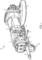
- an embodiment of a power tool in this case an angle grinder 10, is depicted with a tethering attachment assembly 100. While an angle grinder 10 is depicted herein by way of example, it will be readily appreciated that the described tethering attachment assembly 100 may be utilized with any power tool, including but not limited to, sanders, saws, impact drivers, hammers, etc. Additionally, the tethering attachment assembly 100 may be employed for any other apparatus, including but not limited to, hand tools, outdoor products, power generators, etc. that may be used at higher ground.
- the angle grinder 10 includes a housing having a handle portion 14, a field case 16, and a gear case 18.
- the handle portion 14 is fixedly attached to a first end of the field case 16, and the gear case 18 is fixedly attached to a second end of the field case 16.
- the field case 16 supports a motor (not shown) having a motor spindle that extends into the gear case 18 for driving gearset supported therein.
- a wheel spindle (not shown) extends from gear case and is driven by the motor spindle through the gearset.
- the axis of rotation of motor spindle is generally perpendicular to the axis of rotation of the wheel spindle.
- a grinder wheel (not shown) is selectively attachable to the wheel spindle and is rotatably driven thereby.
- the grinder wheel is guarded by a wheel guard 36.
- power tool 10 is a corded tool, where the handle portion 14 includes an opening 44 at its distal end opposite the connection end to the field case 16, through which a power cord 45 is received.
- power tool 10 may be cordless having a battery receptacle for receiving one or more battery packs.
- the motor is in electrical communication with a switch (not shown).
- the switch is in turn in contact with a power source via power cord 42.
- a trigger 46 is in mechanical communication with the switch for selectively supplying power from the power source to the motor. Mechanical actuation of the trigger 46 may result in actuation of the switch, which activates the motor.
- tethering attachment assembly 100 is removeably attached to a lower rear end 48 of the handle portion 14 below the opening 44 and the power cord 42.
- the end 28 of the handle portion 14 is provided with a pair of elongated slots 50 around the opening 44 for receiving a pair of elongated posts 102 of the tethering attachment assembly 100, as discussed below.
- a pair of side through-holes or receptacles 52 are provided intersecting the elongated slots 50.
- a pair of pins or fasteners 54 are received through the through-holes or receptacles 52 to securely hold the posts 102 of tethering attachment assembly 100 within the elongated slots 50.
- the tethering attachment assembly 100 provides an attachment point for the user to attach a lanyard in order to protect the tool in the event of a fall.
- the advantages of this tethering attachment assembly 100 are discussed in detail below.
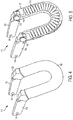
- Fig. 3 depicts a perspective view of the tethering attachment assembly, according to an embodiment.
- the tethering attachment assembly 100 integrally includes a coil element 110.
- coil element 110 is made of elastic metal as a compression spring treated to be deformable upon application of heavy force exceeding a limit.
- the coil element 110 is designed and manufactured in a way that it resiliently yields and deforms against application of significant kinetic energy resulting from a fall or drop at high height.
- a sleeve 112 made of a webbing of material, e.g., nylon, ballistic nylon, synthetic fiber, polypropylene, or cotton, or of plastic material.
- sleeve 112 substantially covers the coil element 110.
- the sleeve 112 is partially depicted to expose part of the coil element 110, though it must be understood that the sleeve 112 substantially covers the entire length of the coil element 110.
- the sleeve 112 is tubularly disposed around the coil element 110 and fastened to the ends of the coil element 110 to restrain the coil from being stretched under normal use operation. However, in the event of a fall at height, the sleeve 112 tears away under heavy stress, allowing the coil element 110 to deform and be exposed to the user.
- ends of the coil element 110 include extended portions 116 attached to posts 102 via rivets 106.
- a secondary sleeve 114 such as a heat-shrink tubing, is disposed at the ends of the sleeve 112 and/or the extended portions 116.
- the two posts 102 are brought close together and inserted into elongated slots 50 of the power tool 10.
- the coil element 110 is bent to form a substantially U-shaped hook.
- a lanyard may be attached to the tethering attachment assembly 100 (e.g., directly or via a carabiner) when the power tool 10 is in use at higher grounds.
- a lanyard may refer to any cable, strap, rope or cord, typically with "ready to use” terminations such as hooks or carabiners, intended for securing objects for "at height” use.
- the coil element 110 significantly absorbs the energy of the fall, which can be significant depending on the mass of tool and distance dropped. In most instances, i.e., where the length of the lanyard is relatively small and the power tool 10 is not too heavy, the coil element 110 likely absorbs the kinetic energy of the fall without damage or deformity to the tethering attachment assembly 100 or the power tool 10. However, where the distance of the drop is too long and/or the tool 10 is too heavy, the likelihood of the drop damaging the power tool internal components is high. In this case, while the coil element 110 absorbs some of the kinetic energy of the fall, it will deform and rip the sleeve 112 if the kinetic energy of the fall exceeds a predetermined limit. This notified the user that the power tool 10 has been dropped and likely damaged.
- Figs. 4 and 5 depict two perspective views of an alternative tethering attachment assembly, the latter showing a plastic cover transparently, according to an embodiment.
- the sleeve 120 covers not only the coil element 110, but also the extended portions 116.
- the secondary sleeve 122 which in an embodiment is made of heat-shrink tubing, covers the attachment points of the extended portions 116 to the posts 102, including rivets 106.
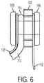
- Fig. 6 depicts a side view of the riveting connection between the extended portion 116 of the coil element 110 and the post 102, according to an embodiment.
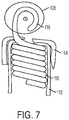
- Fig. 7 depicts a cross sectional view of the same riveting connection, according to an embodiment.
- the extended portion 116 wraps around the axis of the rivet 106 adjacent the post 102, and the end 108 of the rivet 106 axially secures the extended portion 116 to the post 102.
- the rivet 106 provides some rotational flexibility for the tethering attachment assembly 100.
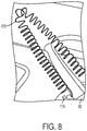
- Fig. 8 depicts a perspective view of a tethering attachment assembly deformed after a power tool drop, according to an embodiment. As shown herein, after application of kinetic force exceeding a threshold amount to the coil element 110, the coil element 110 does not return to its original state and is permanently deformed.
- the size and length of the rivets 106 and posts 102 may be adjusted based on the weight of the tool 10 and the positioning of the tethering attachment assembly 100. Furthermore, the size, thickness, and material used for the coil element 110 and the cover 112 can be adjusted depending on the weight of the tool 10. For example, if the tool mass increased a larger diameter spring wire, spring diameter, and number of turns can be adjusted to change the spring rate and ultimately the energy absorbing characteristics of spring.
- the cover 112 material can be similarly selected to depending on the tool weight and approved height.
- Example embodiments are provided so that this disclosure will be thorough, and will fully convey the scope to those who are skilled in the art. Numerous specific details are set forth such as examples of specific components, devices, and methods, to provide a thorough understanding of embodiments of the present disclosure. It will be apparent to those skilled in the art that specific details need not be employed, that example embodiments may be embodied in many different forms and that neither should be construed to limit the scope of the disclosure. In some example embodiments, well-known processes, well-known device structures, and well-known technologies are not described in detail.
Landscapes
- Engineering & Computer Science (AREA)
- Mechanical Engineering (AREA)
- Emergency Lowering Means (AREA)
- Springs (AREA)
- Percussive Tools And Related Accessories (AREA)
Abstract
Description
- This disclosure relates to a tethering attachment. More particularly, the present invention relates to an impact-absorbing tethering attachment mechanism for use with an apparatus such as a power tool.
- For power tools and hand tools used in construction at high elevation, tool operators often fasten or tether a safety lanyard or hook to the tool to protect the tool, as well as those working at lower levels, in the event the tool is dropped. Without a tether connection, the drop often damages the tool even without direct impact with the ground, as the kinetic energy of the tool is transferred to the tool housing. However, many conventional tools do not provide adequate locations to attach a lanyard, and the user is forced to hook the lanyard directly to, for example, the tool handle. Furthermore, a lanyard suitable for a small tool might not have sufficient strength to handle the weight of a heavier and bulkier tool. In the event of a fall, even without impact with the ground, the energy from the fall often damages the internal components of the tool. What is desired is to provide a connectivity mechanism on the tool itself that would encompass the energy-absorbing characteristics needed to protect the tool.
- According to an embodiment of the invention, a tethering attachment assembly is provided for attachment to an apparatus to facilitate connection of a lanyard to the apparatus. In an embodiment, the tethering attachment assembly includes a pair of posts and a coil element including metallic material that substantially resiliently retains its state with application of force up to a limit, and is permanently plastically deformable upon application of force exceeding the limit, the coil element having two ends attached to the elongated posts and adapted to form a substantially U-shaped hook when the elongated posts are attached to the apparatus. In an embodiment, a sleeve is tubularly disposed around the coil element to substantially cover the coil element.
- In an embodiment, the tethering attachment assembly further includes a pair of rivets that pivotably attach the ends of the coil element to the posts. In an embodiment, the coil element includes extended portions engaging the rivets.
- In an embodiment, the tethering attachment assembly further includes a secondary sleeve disposed at ends of the sleeve. In an embodiment, the secondary sleeve is disposed around attachment points of the coil elements to the posts.
- In an embodiment, the sleeve includes a webbing of material.
- In an embodiment, the sleeve is configured to tear when the coil element is deformed to expose the coil element.
- According to an embodiment of the invention, an apparatus is provided including a housing and a tethering attachment assembly attached to the housing and adapted to facilitate connection of a lanyard to the apparatus. In an embodiment, the tethering attachment assembly includes a pair of posts attached to the housing, and a coil element including metallic material that substantially resiliently retains its state with application of force up to a limit, and is permanently plastically deformable upon application of force exceeding the limit. In an embodiment, the coil element includes two ends attached to the posts and adapted to form a substantially U-shaped hook when the posts are attached to the apparatus. In an embodiment, a sleeve is tubularly disposed around the coil element to substantially cover the coil element.
- In an embodiment, the tethering attachment assembly further includes a pair of rivets that pivotably attach the ends of the coil element to the posts. In an embodiment, the coil element includes extended portions engaging the rivets.
- In an embodiment, the tethering attachment assembly further includes a secondary sleeve disposed at ends of the sleeve. In an embodiment, the secondary sleeve is disposed around attachment points of the coil elements to the posts.
- In an embodiment, the sleeve comprises a webbing. In an embodiment, the sleeve is configured to tear when the coil element is deformed to expose the coil element.
- In an embodiment, the apparatus comprises a power tool having a motor disposed within the housing. In an embodiment, the apparatus comprises a hand tool.
- In an embodiment, the housing defines a pair of elongated slots for receiving the posts therein. In an embodiment, the posts of the tethering attachment assembly are removeably received within the elongated slots of the housing. In an embodiment, the housing includes side through-holes or receptacles arranged to received pins or fasteners for securing the elongated posts of the tethering attachment assembly within the elongated slots of the housing.
- In the accompanying drawings which form part of the specification:
-
Fig. 1 depicts a rear perspective view of a power tool, in accordance with an embodiment. -
Fig. 2 depicts a rear axial view of the power tool, according to an embodiment. -
Fig. 3 depicts a perspective view of a tethering attachment assembly, according to an embodiment. -
Figs. 4 and 5 depict two perspective views of an alternative tethering attachment assembly, the latter showing a sleeve transparently, according to an embodiment. -
Fig. 6 depicts a side video of the riveting connection for the tethering attachment assembly, according to an embodiment. -
Fig. 7 depicts a cross-sectional view of the riveting connection for the tethering attachment assembly, according to an embodiment. -
Fig. 8 depicts a perspective view of a tethering attachment assembly deformed after a power tool drop, according to an embodiment. - Corresponding reference numerals indicate corresponding parts throughout the several figures of the drawings.
- With reference to
Figs. 1 and2 , an embodiment of a power tool, in this case anangle grinder 10, is depicted with atethering attachment assembly 100. While anangle grinder 10 is depicted herein by way of example, it will be readily appreciated that the describedtethering attachment assembly 100 may be utilized with any power tool, including but not limited to, sanders, saws, impact drivers, hammers, etc. Additionally, thetethering attachment assembly 100 may be employed for any other apparatus, including but not limited to, hand tools, outdoor products, power generators, etc. that may be used at higher ground. - According to an embodiment, the
angle grinder 10 includes a housing having ahandle portion 14, afield case 16, and agear case 18. In an embodiment, thehandle portion 14 is fixedly attached to a first end of thefield case 16, and thegear case 18 is fixedly attached to a second end of thefield case 16. In an embodiment, thefield case 16 supports a motor (not shown) having a motor spindle that extends into thegear case 18 for driving gearset supported therein. In an embodiment, a wheel spindle (not shown) extends from gear case and is driven by the motor spindle through the gearset. In an embodiment, the axis of rotation of motor spindle is generally perpendicular to the axis of rotation of the wheel spindle. In an embodiment, a grinder wheel (not shown) is selectively attachable to the wheel spindle and is rotatably driven thereby. In an embodiment, the grinder wheel is guarded by awheel guard 36. - In an embodiment,
power tool 10 is a corded tool, where thehandle portion 14 includes an opening 44 at its distal end opposite the connection end to thefield case 16, through which a power cord 45 is received. Alternatively,power tool 10 may be cordless having a battery receptacle for receiving one or more battery packs. - In an embodiment, the motor is in electrical communication with a switch (not shown). The switch is in turn in contact with a power source via
power cord 42. In an embodiment, atrigger 46 is in mechanical communication with the switch for selectively supplying power from the power source to the motor. Mechanical actuation of thetrigger 46 may result in actuation of the switch, which activates the motor. - In an embodiment,
tethering attachment assembly 100 is removeably attached to a lower rear end 48 of thehandle portion 14 below the opening 44 and thepower cord 42. In an embodiment, the end 28 of thehandle portion 14 is provided with a pair ofelongated slots 50 around the opening 44 for receiving a pair ofelongated posts 102 of thetethering attachment assembly 100, as discussed below. In an embodiment, a pair of side through-holes orreceptacles 52 are provided intersecting theelongated slots 50. A pair of pins orfasteners 54 are received through the through-holes orreceptacles 52 to securely hold theposts 102 oftethering attachment assembly 100 within theelongated slots 50. - In an embodiment, the
tethering attachment assembly 100 provides an attachment point for the user to attach a lanyard in order to protect the tool in the event of a fall. The advantages of thistethering attachment assembly 100 are discussed in detail below. -
Fig. 3 depicts a perspective view of the tethering attachment assembly, according to an embodiment. In an embodiment, thetethering attachment assembly 100 integrally includes acoil element 110. In an embodiment,coil element 110 is made of elastic metal as a compression spring treated to be deformable upon application of heavy force exceeding a limit. Specifically, thecoil element 110 is designed and manufactured in a way that it resiliently yields and deforms against application of significant kinetic energy resulting from a fall or drop at high height. - In an embodiment, a
sleeve 112 made of a webbing of material, e.g., nylon, ballistic nylon, synthetic fiber, polypropylene, or cotton, or of plastic material. In an embodiment,sleeve 112 substantially covers thecoil element 110. InFig. 3 , thesleeve 112 is partially depicted to expose part of thecoil element 110, though it must be understood that thesleeve 112 substantially covers the entire length of thecoil element 110. In an embodiment, thesleeve 112 is tubularly disposed around thecoil element 110 and fastened to the ends of thecoil element 110 to restrain the coil from being stretched under normal use operation. However, in the event of a fall at height, thesleeve 112 tears away under heavy stress, allowing thecoil element 110 to deform and be exposed to the user. - In an embodiment, ends of the
coil element 110 include extendedportions 116 attached toposts 102 viarivets 106. In an embodiment, asecondary sleeve 114, such as a heat-shrink tubing, is disposed at the ends of thesleeve 112 and/or theextended portions 116. - In an embodiment, for attachment of the
tethering attachment assembly 100 to thepower tool 10, the twoposts 102 are brought close together and inserted intoelongated slots 50 of thepower tool 10. To do this, thecoil element 110 is bent to form a substantially U-shaped hook. - In an embodiment, a lanyard may be attached to the tethering attachment assembly 100 (e.g., directly or via a carabiner) when the
power tool 10 is in use at higher grounds. As understood in the industry, and for the purposes of this disclosure, a lanyard may refer to any cable, strap, rope or cord, typically with "ready to use" terminations such as hooks or carabiners, intended for securing objects for "at height" use. - In the event the
power tool 10 is dropped, thecoil element 110 significantly absorbs the energy of the fall, which can be significant depending on the mass of tool and distance dropped. In most instances, i.e., where the length of the lanyard is relatively small and thepower tool 10 is not too heavy, thecoil element 110 likely absorbs the kinetic energy of the fall without damage or deformity to thetethering attachment assembly 100 or thepower tool 10. However, where the distance of the drop is too long and/or thetool 10 is too heavy, the likelihood of the drop damaging the power tool internal components is high. In this case, while thecoil element 110 absorbs some of the kinetic energy of the fall, it will deform and rip thesleeve 112 if the kinetic energy of the fall exceeds a predetermined limit. This notified the user that thepower tool 10 has been dropped and likely damaged. -
Figs. 4 and 5 depict two perspective views of an alternative tethering attachment assembly, the latter showing a plastic cover transparently, according to an embodiment. In this embodiment, thesleeve 120 covers not only thecoil element 110, but also theextended portions 116. In addition, thesecondary sleeve 122, which in an embodiment is made of heat-shrink tubing, covers the attachment points of theextended portions 116 to theposts 102, including rivets 106. -
Fig. 6 depicts a side view of the riveting connection between theextended portion 116 of thecoil element 110 and thepost 102, according to an embodiment.Fig. 7 depicts a cross sectional view of the same riveting connection, according to an embodiment. In an embodiment, theextended portion 116 wraps around the axis of therivet 106 adjacent thepost 102, and theend 108 of therivet 106 axially secures theextended portion 116 to thepost 102. Therivet 106 provides some rotational flexibility for thetethering attachment assembly 100. -
Fig. 8 depicts a perspective view of a tethering attachment assembly deformed after a power tool drop, according to an embodiment. As shown herein, after application of kinetic force exceeding a threshold amount to thecoil element 110, thecoil element 110 does not return to its original state and is permanently deformed. - In an embodiment, the size and length of the
rivets 106 andposts 102 may be adjusted based on the weight of thetool 10 and the positioning of thetethering attachment assembly 100. Furthermore, the size, thickness, and material used for thecoil element 110 and thecover 112 can be adjusted depending on the weight of thetool 10. For example, if the tool mass increased a larger diameter spring wire, spring diameter, and number of turns can be adjusted to change the spring rate and ultimately the energy absorbing characteristics of spring. Thecover 112 material can be similarly selected to depending on the tool weight and approved height. - The foregoing description of the embodiments has been provided for purposes of illustration and description. It is not intended to be exhaustive or to limit the disclosure. Individual elements or features of a particular embodiment are generally not limited to that particular embodiment, but, where applicable, are interchangeable and can be used in a selected embodiment, even if not specifically shown or described. The same may also be varied in many ways. Such variations are not to be regarded as a departure from the disclosure, and all such modifications are intended to be included within the scope of the disclosure.
- Example embodiments are provided so that this disclosure will be thorough, and will fully convey the scope to those who are skilled in the art. Numerous specific details are set forth such as examples of specific components, devices, and methods, to provide a thorough understanding of embodiments of the present disclosure. It will be apparent to those skilled in the art that specific details need not be employed, that example embodiments may be embodied in many different forms and that neither should be construed to limit the scope of the disclosure. In some example embodiments, well-known processes, well-known device structures, and well-known technologies are not described in detail.
- The terminology used herein is for the purpose of describing particular example embodiments only and is not intended to be limiting. As used herein, the singular forms "a," "an," and "the" may be intended to include the plural forms as well, unless the context clearly indicates otherwise. The terms "comprises," "comprising," "including," and "having," are inclusive and therefore specify the presence of stated features, integers, steps, operations, elements, and/or components, but do not preclude the presence or addition of one or more other features, integers, steps, operations, elements, components, and/or groups thereof. The method steps, processes, and operations described herein are not to be construed as necessarily requiring their performance in the particular order discussed or illustrated, unless specifically identified as an order of performance. It is also to be understood that additional or alternative steps may be employed.
Claims (15)
- A tethering attachment assembly adapted for attachment to an apparatus to facilitate connection of a lanyard to the apparatus, the tethering attachment assembly comprising:a pair of posts;a coil element comprising metallic material that substantially resiliently retains its state with application of force up to a limit, and is permanently plastically deformable upon application of force exceeding the limit, the coil element having two ends attached to the elongated posts and adapted to form a substantially U-shaped hook when the elongated posts are attached to the apparatus; anda sleeve tubularly disposed around the coil element to substantially cover the coil element.
- The tethering attachment assembly of claim 2, further comprising a pair of rivets that pivotably attach the ends of the coil element to the posts.
- The tethering attachment assembly of claim 3, wherein the coil element comprises extended portions engaging the rivets.
- The tethering attachment assembly of claim 1, further comprising a secondary sleeve disposed at ends of the sleeve.
- The tethering attachment assembly of claim 4, wherein the secondary sleeve is disposed around attachment points of the coil elements to the posts.
- The tethering attachment assembly of claim 1, wherein the sleeve comprises a webbing of material.
- The tethering attachment assembly of claim 1, wherein the sleeve is configured to tear when the coil element is deformed to expose the coil element.
- An apparatus comprising:a housing; anda tethering attachment assembly attached to the housing and adapted to facilitate connection of a lanyard to the apparatus, the tethering attachment assembly comprising:a pair of posts attached to the housing;a coil element comprising metallic material that substantially resiliently retains its state with application of force up to a limit, and is permanently plastically deformable upon application of force exceeding the limit, the coil element having two ends attached to the posts and adapted to form a substantially U-shaped hook when the posts are attached to the apparatus; anda sleeve tubularly disposed around the coil element to substantially cover the coil element.
- The apparatus of claim 8, wherein the tethering attachment assembly further comprising a pair of rivets that pivotably attach the ends of the coil element to the posts.
- The apparatus of claim 8, wherein the sleeve is configured to tear when the coil element is deformed to expose the coil element.
- The apparatus of claim 8, wherein the apparatus comprises a power tool having a motor disposed within the housing.
- The apparatus of claim 8, wherein the apparatus comprises a hand tool.
- The apparatus of claim 8, wherein the housing defines a pair of elongated slots for receiving the posts therein.
- The apparatus of claim 13, wherein the posts of the tethering attachment assembly are removeably received within the elongated slots of the housing.
- The apparatus of claim 14, wherein the housing includes side through-holes or receptacles arranged to received pins or fasteners for securing the elongated posts of the tethering attachment assembly within the elongated slots of the housing.
Applications Claiming Priority (1)
| Application Number | Priority Date | Filing Date | Title |
|---|---|---|---|
| US201562249734P | 2015-11-02 | 2015-11-02 |
Publications (3)
| Publication Number | Publication Date |
|---|---|
| EP3168010A2 true EP3168010A2 (en) | 2017-05-17 |
| EP3168010A3 EP3168010A3 (en) | 2017-08-16 |
| EP3168010B1 EP3168010B1 (en) | 2018-09-26 |
Family
ID=57240904
Family Applications (1)
| Application Number | Title | Priority Date | Filing Date |
|---|---|---|---|
| EP16196810.2A Active EP3168010B1 (en) | 2015-11-02 | 2016-11-02 | Impact-absorbing tethering attachment |
Country Status (2)
| Country | Link |
|---|---|
| US (2) | US10045606B2 (en) |
| EP (1) | EP3168010B1 (en) |
Families Citing this family (27)
| Publication number | Priority date | Publication date | Assignee | Title |
|---|---|---|---|---|
| USD775517S1 (en) * | 2015-02-05 | 2017-01-03 | Tenacious Holdings, Inc. | Coil lanyard |
| US10045606B2 (en) | 2015-11-02 | 2018-08-14 | Black & Decker Inc. | Impact-absorbing tethering attachment |
| US10668608B2 (en) * | 2016-02-10 | 2020-06-02 | Illinois Tool Works Inc. | Fastener driving tool |
| US9968180B2 (en) * | 2016-09-12 | 2018-05-15 | Ty-Flot, Inc. | Drop prevention apparatus and system for hand tools |
| US10449662B2 (en) | 2016-11-16 | 2019-10-22 | Ty-Flot, Inc. | Tethering assembly and method for grinders and like tools |
| USD873119S1 (en) * | 2016-11-16 | 2020-01-21 | Pure Safety Group, Inc. | Tethering assembly for hand grinders and like tools |
| US10932550B2 (en) * | 2017-02-03 | 2021-03-02 | Hewlett-Packard Development Company, L.P. | Lanyard attachment for an input device |
| EP3517254B1 (en) | 2018-01-09 | 2021-11-10 | Black & Decker Inc. | Tethering system for power tool and battery pack |
| US11504840B2 (en) | 2018-01-09 | 2022-11-22 | Black & Decker Inc. | Tethering system for power tool and battery pack |
| JP7123592B2 (en) * | 2018-03-23 | 2022-08-23 | 株式会社マキタ | Power tools and power tool couplings |
| US11964356B2 (en) * | 2018-04-05 | 2024-04-23 | Makita Corporation | Hand-held tool |
| JP7237509B2 (en) | 2018-10-05 | 2023-03-13 | 株式会社マキタ | power tools and hooks |
| FR3089839B1 (en) | 2018-12-14 | 2021-07-23 | Renault Georges Ets | Optimized restraint system |
| EP3908429B1 (en) | 2019-01-10 | 2025-04-09 | Milwaukee Electric Tool Corporation | Power tool |
| JP7337530B2 (en) * | 2019-04-05 | 2023-09-04 | 株式会社マキタ | power tools and tool holders |
| EP4000812A3 (en) * | 2020-10-29 | 2022-08-03 | Black & Decker Inc. | Lanyard |
| DE102020216582A1 (en) * | 2020-12-29 | 2022-06-30 | Robert Bosch Gesellschaft mit beschränkter Haftung | hand tool |
| US12611761B2 (en) | 2021-11-24 | 2026-04-28 | Milwaukee Electric Tool Corporation | Grinder including enhanced sensing and component detection |
| DE112023000567T5 (en) | 2022-02-18 | 2025-01-30 | Milwaukee Electric Tool Corporation | POWERED FASTENER DRIVER |
| JP7773095B2 (en) * | 2022-02-28 | 2025-11-19 | 工機ホールディングス株式会社 | Work equipment |
| USD1024557S1 (en) | 2022-06-08 | 2024-04-30 | Yeti Coolers, Llc | Container |
| US11912477B2 (en) | 2022-06-08 | 2024-02-27 | Yeti Coolers, Llc | Container with handle and latching system |
| USD1036116S1 (en) | 2022-06-08 | 2024-07-23 | Yeti Coolers, Llc | Container |
| USD1063376S1 (en) | 2022-06-08 | 2025-02-25 | Yeti Coolers, Llc | Container |
| US12466049B2 (en) | 2022-11-15 | 2025-11-11 | Milwaukee Electric Tool Corporation | Power tool with tether |
| USD1036119S1 (en) | 2022-11-30 | 2024-07-23 | Yeti Coolers, Llc | Container |
| US12515303B2 (en) | 2023-05-05 | 2026-01-06 | Milwaukee Electric Tool Corporation | Powered fastener driver |
Family Cites Families (47)
| Publication number | Priority date | Publication date | Assignee | Title |
|---|---|---|---|---|
| DE3222762C2 (en) * | 1982-06-18 | 1986-04-24 | Torbjörn Götene Olsen | Holder for a chuck key or the like. A machine tool |
| US4678059A (en) * | 1986-05-27 | 1987-07-07 | Bowker Thomas K | Rope descending device |
| US5332071A (en) * | 1993-03-09 | 1994-07-26 | Sinco Incorporated | Shock absorber for safety cable system |
| JP3031223U (en) * | 1996-02-16 | 1996-11-22 | 有限会社ヨネノイデザイン | Prop organizer |
| WO1999030603A1 (en) * | 1997-12-18 | 1999-06-24 | The United States Of America | A rappel tool and methods for descent of a load and a rappel tool and stirrup assembly |
| JP2001170878A (en) | 1999-12-14 | 2001-06-26 | Makita Corp | Portable type rotary tool |
| US6776317B1 (en) | 2001-03-19 | 2004-08-17 | Parker Systems, Inc. | Tool lanyard for holding tools |
| USD458533S1 (en) * | 2001-03-19 | 2002-06-11 | Richard O. Sonju | Tether coupler for placement on a rope without passing a rope end therethrough |
| US20030102342A1 (en) * | 2001-12-04 | 2003-06-05 | Larry Fogg | Tool tethering method and apparatus |
| US6868586B1 (en) * | 2002-08-14 | 2005-03-22 | Nz Manufacturing, Inc. | Fastening means for a bungie cord |
| US20040200436A1 (en) * | 2003-02-24 | 2004-10-14 | Staack Lavra A Saylor | Spring tether |
| US6835032B1 (en) | 2003-09-05 | 2004-12-28 | Credo Technology Corporation | Rotary power hand tool having a flexible handle and attachment system |
| US7093329B1 (en) * | 2004-10-19 | 2006-08-22 | Ciber Chiu | Elastic snapping device |
| CA2509084A1 (en) | 2005-06-02 | 2006-12-02 | Martin Arndt | Quick connect break-away tool tether |
| US7458135B2 (en) * | 2005-11-21 | 2008-12-02 | Castle Mountain Enterprises, Llc | Tether |
| US20080163464A1 (en) * | 2007-01-04 | 2008-07-10 | Raymond Baumann | Safety cable for holding tools |
| DE202008007870U1 (en) * | 2008-06-12 | 2008-08-28 | Skylotec Gmbh | Connecting means for a fall protection |
| US8919629B2 (en) * | 2008-08-08 | 2014-12-30 | Darrell A. Moreau | Tool belt mountable device for retractable tool lanyards |
| US20100147912A1 (en) | 2008-12-12 | 2010-06-17 | Hammerhead Industries, Inc. | Heavy Tool Tether |
| US20100163338A1 (en) * | 2008-12-26 | 2010-07-01 | Wood Norman E | Lightweight controlled descent system with an integral reserve suspension relief strap (RSRS) |
| US7819787B2 (en) * | 2008-12-29 | 2010-10-26 | Bodylastics International, Inc. | Resistance training exercise device, system and method |
| US8646768B2 (en) * | 2009-03-16 | 2014-02-11 | Python Safety, Inc. | Quick spin holder for tools and accessories |
| USD618536S1 (en) * | 2009-09-29 | 2010-06-29 | Eason Ricky N | Flower pot anchor |
| US20120168472A1 (en) * | 2010-12-29 | 2012-07-05 | William Mathews | Drop Prevention Tool Holsters |
| US8567290B2 (en) * | 2011-01-07 | 2013-10-29 | Darrell A. Moreau | Retrofit system for tethering a hand tool |
| US8403132B2 (en) | 2011-03-30 | 2013-03-26 | Darrell A. Moreau | Retractable tooling apparatus and tool pouch |
| US20120267403A1 (en) * | 2011-04-25 | 2012-10-25 | Ward Jr Leonard Darnell | Tool Safety Wrist Strap |
| JP2013059837A (en) | 2011-09-14 | 2013-04-04 | Makita Corp | Power tool, and suspension device for the power tool |
| USD710186S1 (en) * | 2011-11-12 | 2014-08-05 | James J. Earley | Flexible support arm |
| GB2500666A (en) | 2012-03-29 | 2013-10-02 | Tool Rrest Ltd | Tool tethers |
| US9232850B2 (en) * | 2012-05-10 | 2016-01-12 | Darrell A. Moreau | Combination tool carrier and carrier securing lanyard |
| WO2013166748A1 (en) * | 2012-05-10 | 2013-11-14 | He Shaodun | Suspension device |
| USD706123S1 (en) * | 2012-06-07 | 2014-06-03 | Python Safety, Inc. | Coiled chain with clasps |
| US9339100B2 (en) * | 2012-07-10 | 2016-05-17 | Ty-Flot, Inc. | Lanyard attachment assembly |
| USD676311S1 (en) * | 2012-08-15 | 2013-02-19 | Darrell A. Moreau | Lanyard attachment assembly |
| USD679577S1 (en) * | 2012-08-22 | 2013-04-09 | Darrell A. Moreau | Lanyard attachment assembly |
| US10207131B2 (en) * | 2013-09-06 | 2019-02-19 | 1078955 Bc Ltd. | Anchorage connector for a safety system |
| USD789188S1 (en) * | 2013-09-09 | 2017-06-13 | Tenacious Holdings, Inc. | Lanyard |
| US9833893B2 (en) * | 2013-09-27 | 2017-12-05 | Ty-Flot, Inc. | Drop-prevention pouch for cordless power tools |
| USD713240S1 (en) * | 2014-04-01 | 2014-09-16 | Allen Chance | Musical instrument strap retainer |
| US9791102B2 (en) * | 2014-09-15 | 2017-10-17 | Ty-Flot | Lanyard slider with implement holders |
| US9801457B2 (en) * | 2014-11-07 | 2017-10-31 | Ty-Flot, Inc. | Tool collet for securing a hand tool to a tool lanyard |
| USD775517S1 (en) * | 2015-02-05 | 2017-01-03 | Tenacious Holdings, Inc. | Coil lanyard |
| US20160227911A1 (en) * | 2015-02-10 | 2016-08-11 | DB Products Group LLC | Tool harness |
| US10377033B2 (en) * | 2015-03-04 | 2019-08-13 | Ty-Flot, Inc. | Method of tethering a tool |
| US10081096B2 (en) * | 2015-03-04 | 2018-09-25 | Ty-Flot, Inc. | Method of tethering a tool |
| US10045606B2 (en) * | 2015-11-02 | 2018-08-14 | Black & Decker Inc. | Impact-absorbing tethering attachment |
-
2016
- 2016-11-01 US US15/340,228 patent/US10045606B2/en active Active
- 2016-11-02 EP EP16196810.2A patent/EP3168010B1/en active Active
-
2018
- 2018-07-17 US US16/037,086 patent/US10136722B1/en active Active
Non-Patent Citations (1)
| Title |
|---|
| None |
Also Published As
| Publication number | Publication date |
|---|---|
| US20170119137A1 (en) | 2017-05-04 |
| US20180317636A1 (en) | 2018-11-08 |
| EP3168010B1 (en) | 2018-09-26 |
| US10136722B1 (en) | 2018-11-27 |
| US10045606B2 (en) | 2018-08-14 |
| EP3168010A3 (en) | 2017-08-16 |
Similar Documents
| Publication | Publication Date | Title |
|---|---|---|
| US10136722B1 (en) | Impact-absorbing tethering attachment | |
| US11173593B2 (en) | Tethering assembly and method for grinders and like tools | |
| US20230066276A1 (en) | Tethering system for power tool and battery pack | |
| US8646768B2 (en) | Quick spin holder for tools and accessories | |
| CN111791193B (en) | Power tool and tool holder | |
| US8348695B2 (en) | Cord protector for power tools | |
| US8035955B2 (en) | Cord protector for power tools | |
| US20120247994A1 (en) | Retractable tooling apparatus and tool pouch | |
| US9451819B2 (en) | Tool cinch with stabilizing wings | |
| US11980281B2 (en) | Lanyard | |
| US11772254B2 (en) | Power tool and hook | |
| EP3517254B1 (en) | Tethering system for power tool and battery pack | |
| US9986815B2 (en) | Drop-prevention tool harness for pistol-grip hand tools | |
| EP2581175A1 (en) | Cord protector for power tools | |
| US20120113571A1 (en) | Cord Protector for Power Tools | |
| TWI630990B (en) | Fastening tool with removable workpiece contact unit | |
| DE10042178C1 (en) | Hand-operated electric tool, e.g. electric drill or hammer-drill, has safety cord for preventing tool dropping onto worker below | |
| US20150246455A1 (en) | Remote cutting tool | |
| US20190250053A1 (en) | Lanyard with stress indicator | |
| JP5767960B2 (en) | Portable work machine | |
| US10875169B2 (en) | Cordless anchor setting tool | |
| KR20140000131U (en) | Grinder apparatus for preventing slide | |
| CN106041837A (en) | Electric tool | |
| KR20220066561A (en) | Hammering device for indirect live wire work | |
| CA2553112A1 (en) | Tool vest |
Legal Events
| Date | Code | Title | Description |
|---|---|---|---|
| PUAI | Public reference made under article 153(3) epc to a published international application that has entered the european phase |
Free format text: ORIGINAL CODE: 0009012 |
|
| STAA | Information on the status of an ep patent application or granted ep patent |
Free format text: STATUS: THE APPLICATION HAS BEEN PUBLISHED |
|
| AK | Designated contracting states |
Kind code of ref document: A2 Designated state(s): AL AT BE BG CH CY CZ DE DK EE ES FI FR GB GR HR HU IE IS IT LI LT LU LV MC MK MT NL NO PL PT RO RS SE SI SK SM TR |
|
| AX | Request for extension of the european patent |
Extension state: BA ME |
|
| PUAL | Search report despatched |
Free format text: ORIGINAL CODE: 0009013 |
|
| AK | Designated contracting states |
Kind code of ref document: A3 Designated state(s): AL AT BE BG CH CY CZ DE DK EE ES FI FR GB GR HR HU IE IS IT LI LT LU LV MC MK MT NL NO PL PT RO RS SE SI SK SM TR |
|
| AX | Request for extension of the european patent |
Extension state: BA ME |
|
| RIC1 | Information provided on ipc code assigned before grant |
Ipc: A45F 5/00 20060101ALI20170712BHEP Ipc: B25F 5/02 20060101AFI20170712BHEP |
|
| STAA | Information on the status of an ep patent application or granted ep patent |
Free format text: STATUS: REQUEST FOR EXAMINATION WAS MADE |
|
| 17P | Request for examination filed |
Effective date: 20170829 |
|
| RBV | Designated contracting states (corrected) |
Designated state(s): AL AT BE BG CH CY CZ DE DK EE ES FI FR GB GR HR HU IE IS IT LI LT LU LV MC MK MT NL NO PL PT RO RS SE SI SK SM TR |
|
| GRAP | Despatch of communication of intention to grant a patent |
Free format text: ORIGINAL CODE: EPIDOSNIGR1 |
|
| STAA | Information on the status of an ep patent application or granted ep patent |
Free format text: STATUS: GRANT OF PATENT IS INTENDED |
|
| RIC1 | Information provided on ipc code assigned before grant |
Ipc: B25F 5/02 20060101AFI20180322BHEP Ipc: A45F 5/00 20060101ALI20180322BHEP |
|
| INTG | Intention to grant announced |
Effective date: 20180410 |
|
| GRAS | Grant fee paid |
Free format text: ORIGINAL CODE: EPIDOSNIGR3 |
|
| GRAA | (expected) grant |
Free format text: ORIGINAL CODE: 0009210 |
|
| STAA | Information on the status of an ep patent application or granted ep patent |
Free format text: STATUS: THE PATENT HAS BEEN GRANTED |
|
| AK | Designated contracting states |
Kind code of ref document: B1 Designated state(s): AL AT BE BG CH CY CZ DE DK EE ES FI FR GB GR HR HU IE IS IT LI LT LU LV MC MK MT NL NO PL PT RO RS SE SI SK SM TR |
|
| REG | Reference to a national code |
Ref country code: GB Ref legal event code: FG4D |
|
| REG | Reference to a national code |
Ref country code: CH Ref legal event code: EP |
|
| REG | Reference to a national code |
Ref country code: AT Ref legal event code: REF Ref document number: 1045445 Country of ref document: AT Kind code of ref document: T Effective date: 20181015 |
|
| REG | Reference to a national code |
Ref country code: IE Ref legal event code: FG4D |
|
| REG | Reference to a national code |
Ref country code: DE Ref legal event code: R096 Ref document number: 602016005999 Country of ref document: DE |
|
| REG | Reference to a national code |
Ref country code: NL Ref legal event code: MP Effective date: 20180926 |
|
| PG25 | Lapsed in a contracting state [announced via postgrant information from national office to epo] |
Ref country code: NO Free format text: LAPSE BECAUSE OF FAILURE TO SUBMIT A TRANSLATION OF THE DESCRIPTION OR TO PAY THE FEE WITHIN THE PRESCRIBED TIME-LIMIT Effective date: 20181226 Ref country code: LT Free format text: LAPSE BECAUSE OF FAILURE TO SUBMIT A TRANSLATION OF THE DESCRIPTION OR TO PAY THE FEE WITHIN THE PRESCRIBED TIME-LIMIT Effective date: 20180926 Ref country code: GR Free format text: LAPSE BECAUSE OF FAILURE TO SUBMIT A TRANSLATION OF THE DESCRIPTION OR TO PAY THE FEE WITHIN THE PRESCRIBED TIME-LIMIT Effective date: 20181227 Ref country code: RS Free format text: LAPSE BECAUSE OF FAILURE TO SUBMIT A TRANSLATION OF THE DESCRIPTION OR TO PAY THE FEE WITHIN THE PRESCRIBED TIME-LIMIT Effective date: 20180926 Ref country code: FI Free format text: LAPSE BECAUSE OF FAILURE TO SUBMIT A TRANSLATION OF THE DESCRIPTION OR TO PAY THE FEE WITHIN THE PRESCRIBED TIME-LIMIT Effective date: 20180926 Ref country code: BG Free format text: LAPSE BECAUSE OF FAILURE TO SUBMIT A TRANSLATION OF THE DESCRIPTION OR TO PAY THE FEE WITHIN THE PRESCRIBED TIME-LIMIT Effective date: 20181226 |
|
| REG | Reference to a national code |
Ref country code: LT Ref legal event code: MG4D |
|
| PG25 | Lapsed in a contracting state [announced via postgrant information from national office to epo] |
Ref country code: LV Free format text: LAPSE BECAUSE OF FAILURE TO SUBMIT A TRANSLATION OF THE DESCRIPTION OR TO PAY THE FEE WITHIN THE PRESCRIBED TIME-LIMIT Effective date: 20180926 Ref country code: AL Free format text: LAPSE BECAUSE OF FAILURE TO SUBMIT A TRANSLATION OF THE DESCRIPTION OR TO PAY THE FEE WITHIN THE PRESCRIBED TIME-LIMIT Effective date: 20180926 Ref country code: HR Free format text: LAPSE BECAUSE OF FAILURE TO SUBMIT A TRANSLATION OF THE DESCRIPTION OR TO PAY THE FEE WITHIN THE PRESCRIBED TIME-LIMIT Effective date: 20180926 |
|
| REG | Reference to a national code |
Ref country code: AT Ref legal event code: MK05 Ref document number: 1045445 Country of ref document: AT Kind code of ref document: T Effective date: 20180926 |
|
| PG25 | Lapsed in a contracting state [announced via postgrant information from national office to epo] |
Ref country code: IT Free format text: LAPSE BECAUSE OF FAILURE TO SUBMIT A TRANSLATION OF THE DESCRIPTION OR TO PAY THE FEE WITHIN THE PRESCRIBED TIME-LIMIT Effective date: 20180926 Ref country code: EE Free format text: LAPSE BECAUSE OF FAILURE TO SUBMIT A TRANSLATION OF THE DESCRIPTION OR TO PAY THE FEE WITHIN THE PRESCRIBED TIME-LIMIT Effective date: 20180926 Ref country code: NL Free format text: LAPSE BECAUSE OF FAILURE TO SUBMIT A TRANSLATION OF THE DESCRIPTION OR TO PAY THE FEE WITHIN THE PRESCRIBED TIME-LIMIT Effective date: 20180926 Ref country code: RO Free format text: LAPSE BECAUSE OF FAILURE TO SUBMIT A TRANSLATION OF THE DESCRIPTION OR TO PAY THE FEE WITHIN THE PRESCRIBED TIME-LIMIT Effective date: 20180926 Ref country code: CZ Free format text: LAPSE BECAUSE OF FAILURE TO SUBMIT A TRANSLATION OF THE DESCRIPTION OR TO PAY THE FEE WITHIN THE PRESCRIBED TIME-LIMIT Effective date: 20180926 Ref country code: ES Free format text: LAPSE BECAUSE OF FAILURE TO SUBMIT A TRANSLATION OF THE DESCRIPTION OR TO PAY THE FEE WITHIN THE PRESCRIBED TIME-LIMIT Effective date: 20180926 Ref country code: AT Free format text: LAPSE BECAUSE OF FAILURE TO SUBMIT A TRANSLATION OF THE DESCRIPTION OR TO PAY THE FEE WITHIN THE PRESCRIBED TIME-LIMIT Effective date: 20180926 Ref country code: IS Free format text: LAPSE BECAUSE OF FAILURE TO SUBMIT A TRANSLATION OF THE DESCRIPTION OR TO PAY THE FEE WITHIN THE PRESCRIBED TIME-LIMIT Effective date: 20190126 Ref country code: PL Free format text: LAPSE BECAUSE OF FAILURE TO SUBMIT A TRANSLATION OF THE DESCRIPTION OR TO PAY THE FEE WITHIN THE PRESCRIBED TIME-LIMIT Effective date: 20180926 |
|
| PG25 | Lapsed in a contracting state [announced via postgrant information from national office to epo] |
Ref country code: SK Free format text: LAPSE BECAUSE OF FAILURE TO SUBMIT A TRANSLATION OF THE DESCRIPTION OR TO PAY THE FEE WITHIN THE PRESCRIBED TIME-LIMIT Effective date: 20180926 Ref country code: PT Free format text: LAPSE BECAUSE OF FAILURE TO SUBMIT A TRANSLATION OF THE DESCRIPTION OR TO PAY THE FEE WITHIN THE PRESCRIBED TIME-LIMIT Effective date: 20190126 Ref country code: SM Free format text: LAPSE BECAUSE OF FAILURE TO SUBMIT A TRANSLATION OF THE DESCRIPTION OR TO PAY THE FEE WITHIN THE PRESCRIBED TIME-LIMIT Effective date: 20180926 |
|
| REG | Reference to a national code |
Ref country code: DE Ref legal event code: R097 Ref document number: 602016005999 Country of ref document: DE |
|
| PG25 | Lapsed in a contracting state [announced via postgrant information from national office to epo] |
Ref country code: MC Free format text: LAPSE BECAUSE OF FAILURE TO SUBMIT A TRANSLATION OF THE DESCRIPTION OR TO PAY THE FEE WITHIN THE PRESCRIBED TIME-LIMIT Effective date: 20180926 Ref country code: DK Free format text: LAPSE BECAUSE OF FAILURE TO SUBMIT A TRANSLATION OF THE DESCRIPTION OR TO PAY THE FEE WITHIN THE PRESCRIBED TIME-LIMIT Effective date: 20180926 Ref country code: LU Free format text: LAPSE BECAUSE OF NON-PAYMENT OF DUE FEES Effective date: 20181102 |
|
| PLBE | No opposition filed within time limit |
Free format text: ORIGINAL CODE: 0009261 |
|
| STAA | Information on the status of an ep patent application or granted ep patent |
Free format text: STATUS: NO OPPOSITION FILED WITHIN TIME LIMIT |
|
| REG | Reference to a national code |
Ref country code: BE Ref legal event code: MM Effective date: 20181130 |
|
| REG | Reference to a national code |
Ref country code: IE Ref legal event code: MM4A |
|
| 26N | No opposition filed |
Effective date: 20190627 |
|
| PG25 | Lapsed in a contracting state [announced via postgrant information from national office to epo] |
Ref country code: SI Free format text: LAPSE BECAUSE OF FAILURE TO SUBMIT A TRANSLATION OF THE DESCRIPTION OR TO PAY THE FEE WITHIN THE PRESCRIBED TIME-LIMIT Effective date: 20180926 Ref country code: FR Free format text: LAPSE BECAUSE OF NON-PAYMENT OF DUE FEES Effective date: 20181126 Ref country code: IE Free format text: LAPSE BECAUSE OF NON-PAYMENT OF DUE FEES Effective date: 20181102 |
|
| PG25 | Lapsed in a contracting state [announced via postgrant information from national office to epo] |
Ref country code: BE Free format text: LAPSE BECAUSE OF NON-PAYMENT OF DUE FEES Effective date: 20181130 |
|
| PG25 | Lapsed in a contracting state [announced via postgrant information from national office to epo] |
Ref country code: MT Free format text: LAPSE BECAUSE OF NON-PAYMENT OF DUE FEES Effective date: 20181102 |
|
| PG25 | Lapsed in a contracting state [announced via postgrant information from national office to epo] |
Ref country code: TR Free format text: LAPSE BECAUSE OF FAILURE TO SUBMIT A TRANSLATION OF THE DESCRIPTION OR TO PAY THE FEE WITHIN THE PRESCRIBED TIME-LIMIT Effective date: 20180926 |
|
| PG25 | Lapsed in a contracting state [announced via postgrant information from national office to epo] |
Ref country code: SE Free format text: LAPSE BECAUSE OF FAILURE TO SUBMIT A TRANSLATION OF THE DESCRIPTION OR TO PAY THE FEE WITHIN THE PRESCRIBED TIME-LIMIT Effective date: 20180926 Ref country code: MK Free format text: LAPSE BECAUSE OF NON-PAYMENT OF DUE FEES Effective date: 20180926 Ref country code: HU Free format text: LAPSE BECAUSE OF FAILURE TO SUBMIT A TRANSLATION OF THE DESCRIPTION OR TO PAY THE FEE WITHIN THE PRESCRIBED TIME-LIMIT; INVALID AB INITIO Effective date: 20161102 Ref country code: CY Free format text: LAPSE BECAUSE OF FAILURE TO SUBMIT A TRANSLATION OF THE DESCRIPTION OR TO PAY THE FEE WITHIN THE PRESCRIBED TIME-LIMIT Effective date: 20180926 |
|
| REG | Reference to a national code |
Ref country code: CH Ref legal event code: PL |
|
| PG25 | Lapsed in a contracting state [announced via postgrant information from national office to epo] |
Ref country code: LI Free format text: LAPSE BECAUSE OF NON-PAYMENT OF DUE FEES Effective date: 20191130 Ref country code: CH Free format text: LAPSE BECAUSE OF NON-PAYMENT OF DUE FEES Effective date: 20191130 |
|
| PGFP | Annual fee paid to national office [announced via postgrant information from national office to epo] |
Ref country code: DE Payment date: 20251118 Year of fee payment: 10 |
|
| PGFP | Annual fee paid to national office [announced via postgrant information from national office to epo] |
Ref country code: GB Payment date: 20251120 Year of fee payment: 10 |