EP3167342B1 - Virtual line-following and retrofit method for autonomous vehicles - Google Patents
Virtual line-following and retrofit method for autonomous vehicles Download PDFInfo
- Publication number
- EP3167342B1 EP3167342B1 EP15770843.9A EP15770843A EP3167342B1 EP 3167342 B1 EP3167342 B1 EP 3167342B1 EP 15770843 A EP15770843 A EP 15770843A EP 3167342 B1 EP3167342 B1 EP 3167342B1
- Authority
- EP
- European Patent Office
- Prior art keywords
- virtual
- robot
- path
- tag
- vehicle
- Prior art date
- Legal status (The legal status is an assumption and is not a legal conclusion. Google has not performed a legal analysis and makes no representation as to the accuracy of the status listed.)
- Active
Links
- 238000000034 method Methods 0.000 title claims description 19
- 230000004807 localization Effects 0.000 claims description 15
- 230000001133 acceleration Effects 0.000 claims description 11
- 230000001419 dependent effect Effects 0.000 claims description 2
- 230000007613 environmental effect Effects 0.000 claims description 2
- 238000013507 mapping Methods 0.000 claims description 2
- 238000009420 retrofitting Methods 0.000 claims description 2
- 238000006073 displacement reaction Methods 0.000 claims 2
- 230000002194 synthesizing effect Effects 0.000 claims 1
- 230000009471 action Effects 0.000 description 3
- 230000008859 change Effects 0.000 description 3
- 230000001939 inductive effect Effects 0.000 description 2
- 238000007726 management method Methods 0.000 description 2
- 230000008569 process Effects 0.000 description 2
- 244000025254 Cannabis sativa Species 0.000 description 1
- 241000196324 Embryophyta Species 0.000 description 1
- 230000006978 adaptation Effects 0.000 description 1
- 230000008901 benefit Effects 0.000 description 1
- 238000004140 cleaning Methods 0.000 description 1
- 238000011217 control strategy Methods 0.000 description 1
- 230000003247 decreasing effect Effects 0.000 description 1
- 230000006870 function Effects 0.000 description 1
- 230000003287 optical effect Effects 0.000 description 1
- 238000005406 washing Methods 0.000 description 1
Images

Classifications
-
- G—PHYSICS
- G05—CONTROLLING; REGULATING
- G05D—SYSTEMS FOR CONTROLLING OR REGULATING NON-ELECTRIC VARIABLES
- G05D1/00—Control of position, course, altitude or attitude of land, water, air or space vehicles, e.g. using automatic pilots
- G05D1/0088—Control of position, course, altitude or attitude of land, water, air or space vehicles, e.g. using automatic pilots characterized by the autonomous decision making process, e.g. artificial intelligence, predefined behaviours
-
- G—PHYSICS
- G05—CONTROLLING; REGULATING
- G05D—SYSTEMS FOR CONTROLLING OR REGULATING NON-ELECTRIC VARIABLES
- G05D1/00—Control of position, course, altitude or attitude of land, water, air or space vehicles, e.g. using automatic pilots
- G05D1/02—Control of position or course in two dimensions
- G05D1/021—Control of position or course in two dimensions specially adapted to land vehicles
- G05D1/0212—Control of position or course in two dimensions specially adapted to land vehicles with means for defining a desired trajectory
- G05D1/0223—Control of position or course in two dimensions specially adapted to land vehicles with means for defining a desired trajectory involving speed control of the vehicle
-
- G—PHYSICS
- G05—CONTROLLING; REGULATING
- G05D—SYSTEMS FOR CONTROLLING OR REGULATING NON-ELECTRIC VARIABLES
- G05D1/00—Control of position, course, altitude or attitude of land, water, air or space vehicles, e.g. using automatic pilots
- G05D1/02—Control of position or course in two dimensions
- G05D1/021—Control of position or course in two dimensions specially adapted to land vehicles
- G05D1/0231—Control of position or course in two dimensions specially adapted to land vehicles using optical position detecting means
- G05D1/0238—Control of position or course in two dimensions specially adapted to land vehicles using optical position detecting means using obstacle or wall sensors
- G05D1/024—Control of position or course in two dimensions specially adapted to land vehicles using optical position detecting means using obstacle or wall sensors in combination with a laser
-
- G—PHYSICS
- G05—CONTROLLING; REGULATING
- G05D—SYSTEMS FOR CONTROLLING OR REGULATING NON-ELECTRIC VARIABLES
- G05D1/00—Control of position, course, altitude or attitude of land, water, air or space vehicles, e.g. using automatic pilots
- G05D1/02—Control of position or course in two dimensions
- G05D1/021—Control of position or course in two dimensions specially adapted to land vehicles
- G05D1/0268—Control of position or course in two dimensions specially adapted to land vehicles using internal positioning means
- G05D1/0272—Control of position or course in two dimensions specially adapted to land vehicles using internal positioning means comprising means for registering the travel distance, e.g. revolutions of wheels
Definitions
- the present invention relates, in embodiments with an autonomous vehicle like, but not exclusively, a wheeled robotized vehicle.
- Autonomous robotized vehicles are self-propelled devices capable of navigating within an environment in a free manner, without constant human support, to perform a desired task.
- Multiple application of robot vehicles have been developed in very different areas including, among others, warehouses, factories, hospitals, nuclear plants, and mines.
- autonomous robots comprise one or more sensors capable of analysing the environment in which the robot is located.
- the sensor may comprise ranging sensors, like for example radars, laser rangefinders, or acoustical rangefinders, bumpers, mechanical feelers, stereo cameras, accelerometers, gyroscopes, compasses, inclinometers, altimeters, or other environmental sensors.
- ranging sensors like for example radars, laser rangefinders, or acoustical rangefinders, bumpers, mechanical feelers, stereo cameras, accelerometers, gyroscopes, compasses, inclinometers, altimeters, or other environmental sensors.
- the present document will refer mainly to laser scanner, without loss of generality, being it intended that the invention may contemplate the use of other suitable sensors based on different principles.
- Sensors are used in the process of mapping, aiming at creating a representation of the environment into which the robot is destined to operate.
- the robot is driven by an operator manually in the environment while the sensors register the position and/or ranges of landmarks in the environment.
- a map of the environment is then generated from the data so collected, usually with the aid of odometry data, by several known methods.
- sensors in the localization of the vehicle in the map which is the determination of the current location and orientation of the robot on the map.
- This can be achieved by internal odometry data alone, provided an initial localization is known (dead reckoning) or, preferably, by a combination of odometry and ranging data.
- the combination of position and orientation is referred to as the 'pose' of the robot and, in the case of 2D motion might be represented by a pair of Cartesian coordinates and one heading angle.
- Sensors are also used as safety device to prevent collisions or minimise their severity: Many autonomous vehicles are equipped with omnidirectional laser scanners for this purpose: the scanners are programmed to generate a collision alert that causes the vehicle to stop when an obstacle is detected within a given safety range. More sophisticated obstacle management strategies are also possible, whereby a robot can be aware of moving obstacles (i.e. persons, other robots, objects that were not originally mapped or that have moved from their original mapped position) and take appropriate measures to prevent crashes.
- moving obstacles i.e. persons, other robots, objects that were not originally mapped or that have moved from their original mapped position
- line-following vehicles that is, vehicles that do not have sophisticated localization and/or navigation capabilities, but are arranged to follow a physical line, for example a buried inductive cable or a line painted on the floor.
- These vehicles include a line sensor that generates an offset signal determined by the distance between the sensor and the centre of the line.
- the robot follows the line by means of a control loop that minimizes the offset while advancing at a given speed.
- Line-following vehicle can be programmed, in a limited fashion, by placing appropriate tags, for example barcodes or inductive RFID tags, along the line.
- tags encode instruction for the robot including, for example, speed commands to accelerate, decelerate, and stop, exchange commands to switch individual vehicles on two different branches of a crossing, and others.
- Figure 2 shows schematically a possible structure of a robotic vehicle 20 according to an aspect of the present invention. It must be understood that this is a conceptual representation and does not reflect all the features of an industrial product.
- the vehicle is shown, to present an example, a tricycle configuration, but it is not intended that the invention be limited to this kinematic system.
- the invention could in fact be applied to any autonomous robot of whatsoever configuration.
- Propulsion of the robot is assured by the motorized wheel 27 that is driven by motor 23, while a second motor or actuator 29 is used to direct the vehicle, by determining the steering angle ⁇ .
- a second motor or actuator 29 is used to direct the vehicle, by determining the steering angle ⁇ .
- the invention since the robot moves in a two-dimensional workspace, at least two independent motors or actuators will be needed for navigation.
- the invention is applicable to systems with any number of motors or actuators and to unidimensional, two-dimensional, or three-dimensional workspaces.
- the motors 23 29 are driven by a drive unit that generates the necessary power signals.
- the drive unit 51 may be of a kind suitable for a line-following robot, arranged for controlling the motors in order to minimize a lateral offset, while the mobile robots advances at a given speed.
- the robot 20 includes also a sensor 21 that provide at least some degree of information about the position of the robot in its workspace.
- the sensor is a 360° laser scanner.
- Such devices are often used in mobile robots for safety and localization purposes, and are available from a number of manufacturers.
- Other devices that may be used as sensor include acoustical rangefinders, radars, optical 3D scanners, tactile sensors, radio receivers, and stereoscopic cameras, but the list is not exhaustive.
- the data generated by the sensor 21 are fused with odometry information gathered from the steering wheel and/or the back wheels 26, by the localization unit 53 that generates, in real time, an estimate of the robot's pose, including for example two linear coordinates x, y, and a yaw angle ⁇ .
- Most robots include, besides the motors 23, 29, other actuators and transducers 57 necessary to accomplish their specific mission, like for example a forklift, tools for washing or cleaning the floor, a blade for cutting grass, a surveillance camera, a prehensile arm, or other.
- the sensor could be controlled by the drive unit 51, as represented, or by another controller means.
- the path 31 (see figure 1 ) that the robot is supposed to follow in the workspace has been defined beforehand, by any suitable method, and is stored in a memory that is accessible by a path following module 55.
- the path is a notional line that joins a starting point A to a destination point B, respecting all the map constraints, like walls 65 and objects 60.
- the computing module receives instantaneous localization data (x, y, ⁇ ) from the localization unit, and synthesizes an offset value, representing the lateral distance between the path line and the center, or another suitable reference point, of the robot 20.
- the offset value is fed to the drive unit 51 that uses it to steer the robot such as to minimize the offset from the path line.
- the drive unit simple turns the steering wheel to the right when the sign of the offset indicates that the path is on that side, and conversely to the left. More advanced control strategies are also possible, however.
- the navigation method of the invention can also be employed to upgrade or retrofit a line-following robot that does not have a complete localization and navigation suite.
- Such robots often include a laser or another sensor for safety purposes that can be used also for localization, and their drive units is configured to respond to an offset signal generated by a line sensor 24.
- the line sensor is disconnected, and the drive unit is given the offset signal synthesized by the path following unit 55 rather than that derived by the physical line.
- the path of the robot can be reprogrammed by software entirely, changing the data used by the path following unit 55, with a minimal intervention on robot's hardware.
- a control system may detect that the path 31 is not practicable, and reprogram the data of the path following unit 55 to send the robot on alternate path 32 instead.
- path crossings and branches are now possible without limitation.
- crossings and branches required special tags that instructed the vehicles on what branch they must follow.
- each robot follows a special virtual path known by its path following unit 55 and no special crossing management is required.
- Moving a robot along a path requires not only the control of the position along a path, but also, for example, managing the speed of the robot. This is traditionally achieved, in line-following robots, by placing tags at suitable points of the path, which are read by a suitable tag reader 25 in the robot. In the frame of the invention, the tags are also virtual, the tag reader is disconnected or omitted, and the path following unit 55 synthesizes tag signals for the drive unit 51 at the appropriate moments and positions so to obtain the desired speed profile. Tags can be used to specify a constant speed, an acceleration or deceleration ramp, or other actions, including sending commands to the robot's actuators and sensors 57.
- the tags may be generated when the robot passes over a predetermined position, thus repeating exactly the functioning of the physical tags, except for the need of sticking or affixing the tag in place.
- the invention can generate tags automatically, not based only on the instant position, but also on the dynamic condition of the robot and on a forthcoming section of the virtual path.
- the system can be programmed to synthesize automatically a slow-down tag 40 before a sharp corner or a braking point, for example by imposing thresholds on the lateral and longitudinal acceleration imposed on the vehicle, and a speed-up tag 45 after the corner.
- Tag generation is based on a following section of the virtual path and not only on the instantaneous location. Deceleration tag 43, for example, will be generated only for vehicles following path 33, but not for those who are on paths 31 or 32.
- Slow-down and stop tags 41 are inserted automatically before the destination points. Any change in the shape of the path automatically causes the corresponding tags to move in the appropriate new positions.
- the path following unit 55 generates a series of tags that specify progressively increasing or decreasing speed, so to obtain a speed ramp.
- the automatic generation of virtual tags enables in fact, full control of the speed of the vehicle in real time. If the drive unit 51 is capable of processing a tag specifying an acceleration or deceleration ramp, the path following unit 55 will generate one single tag to that purpose.
- the invention includes also variants in which the forward speed can be communicated directly and in real time to the drive unit 51. In such cases, acceleration and deceleration ramps could be obtained whenever necessary without generating a virtual tag. Virtual tags causing the vehicle to change its speed could still be generated if convenient, for example for compatibility with legacy systems.
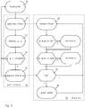
- FIG. 3 illustrates a possible structure of the inventive method.
- the flowchart indicates the steps carried out by the path following unit 55 and those that take place in the drive unit 51.
- the path following unit 55 receives the position data generated by the localization unit (step 71) and generates an offset corresponding to the distance between the vehicle and the virtual path (step 72).
- the virtual path has been defined in a prior planning process that is not indicated in the figure.
- the offset is received by the drive unit (step 82) that steers the vehicle in order to reduce the offset.
- the figure illustrates a very simple method but, in a real implementation, the control scheme could be considerably more advanced.
- the path following unit considers a forthcoming part of the path and forecasts actions that the robot will need to perform.
- the path following unit 55 may compute the acceleration of the vehicle if the path should be followed at the given speed. The acceleration is then checked against defined thresholds for longitudinal acceleration a l and transverse acceleration a t . If one acceleration exceeds a threshold, as it might be the case if the path foresees a tight corner or a hard braking, the path following units 55 will act to ensure that the robot's speed is reduced to a safer value. Conversely, when exiting from a corner or when a situation that required that the robot should advance only slowly is ended, the path following unit will take cause the robot to speed up. In the same way, the path following unit may foresee and arrange the actuation of a forklift or of another actuator 57.
- Robot's action can be commanded directly by the path following unit 55 when a suitable interface exist or, as shown in figure 3 , caused by the generation of one or several virtual tags (step 75) that are received by the drive unit (step 85) which adapts the speed or execute a command (step 86).
Landscapes
- Engineering & Computer Science (AREA)
- Physics & Mathematics (AREA)
- Aviation & Aerospace Engineering (AREA)
- Radar, Positioning & Navigation (AREA)
- Remote Sensing (AREA)
- General Physics & Mathematics (AREA)
- Automation & Control Theory (AREA)
- Optics & Photonics (AREA)
- Electromagnetism (AREA)
- Health & Medical Sciences (AREA)
- Evolutionary Computation (AREA)
- Game Theory and Decision Science (AREA)
- Medical Informatics (AREA)
- Artificial Intelligence (AREA)
- Business, Economics & Management (AREA)
- Control Of Position, Course, Altitude, Or Attitude Of Moving Bodies (AREA)
- Manipulator (AREA)
Description
- The present invention relates, in embodiments with an autonomous vehicle like, but not exclusively, a wheeled robotized vehicle.
- Autonomous robotized vehicles are self-propelled devices capable of navigating within an environment in a free manner, without constant human support, to perform a desired task. Multiple application of robot vehicles have been developed in very different areas including, among others, warehouses, factories, hospitals, nuclear plants, and mines.
- In known applications, such as
US 5 548 511 ,US 2002/0153184 andEP 0 403 390 , autonomous robots comprise one or more sensors capable of analysing the environment in which the robot is located. The sensor may comprise ranging sensors, like for example radars, laser rangefinders, or acoustical rangefinders, bumpers, mechanical feelers, stereo cameras, accelerometers, gyroscopes, compasses, inclinometers, altimeters, or other environmental sensors. The present document will refer mainly to laser scanner, without loss of generality, being it intended that the invention may contemplate the use of other suitable sensors based on different principles. - Sensors are used in the process of mapping, aiming at creating a representation of the environment into which the robot is destined to operate. Typically, the robot is driven by an operator manually in the environment while the sensors register the position and/or ranges of landmarks in the environment. A map of the environment is then generated from the data so collected, usually with the aid of odometry data, by several known methods.
- It is also known to use sensors in the localization of the vehicle in the map, which is the determination of the current location and orientation of the robot on the map. This can be achieved by internal odometry data alone, provided an initial localization is known (dead reckoning) or, preferably, by a combination of odometry and ranging data. The combination of position and orientation is referred to as the 'pose' of the robot and, in the case of 2D motion might be represented by a pair of Cartesian coordinates and one heading angle.
- Sensors are also used as safety device to prevent collisions or minimise their severity: Many autonomous vehicles are equipped with omnidirectional laser scanners for this purpose: the scanners are programmed to generate a collision alert that causes the vehicle to stop when an obstacle is detected within a given safety range. More sophisticated obstacle management strategies are also possible, whereby a robot can be aware of moving obstacles (i.e. persons, other robots, objects that were not originally mapped or that have moved from their original mapped position) and take appropriate measures to prevent crashes.
- Also known are line-following vehicles that is, vehicles that do not have sophisticated localization and/or navigation capabilities, but are arranged to follow a physical line, for example a buried inductive cable or a line painted on the floor. These vehicles include a line sensor that generates an offset signal determined by the distance between the sensor and the centre of the line. The robot follows the line by means of a control loop that minimizes the offset while advancing at a given speed.
- Line-following vehicle can be programmed, in a limited fashion, by placing appropriate tags, for example barcodes or inductive RFID tags, along the line. The tags encode instruction for the robot including, for example, speed commands to accelerate, decelerate, and stop, exchange commands to switch individual vehicles on two different branches of a crossing, and others.
- While line-following vehicles are appreciated for their economy and ruggedness, modifying their missions requires physically moving the lines and the associated tags, which is exceedingly cumbersome, time-consuming, and expensive.
- It is therefore an aim of the present invention to propose a navigation method and a method of retrofitting an existing robot. These aims are achieved by the object of claim 1, while dependent claims relate to advantageous, but optional, features.
- The invention will be better understood with the aid of the description of an embodiment given by way of example and illustrated by the figures, in which:
-
Figure 1 shows schematically a plan of the environment into which a robot operates, with lines corresponding to possible robot tasks. -
Figure 2 illustrates schematically and in simplified form, a possible structure of a robot according to an aspect of the present invention. -
Figure 3 is a flowchart representation of a method according to an aspect of the invention. -
Figure 2 shows schematically a possible structure of arobotic vehicle 20 according to an aspect of the present invention. It must be understood that this is a conceptual representation and does not reflect all the features of an industrial product. The vehicle is shown, to present an example, a tricycle configuration, but it is not intended that the invention be limited to this kinematic system. The invention could in fact be applied to any autonomous robot of whatsoever configuration. - Propulsion of the robot is assured by the
motorized wheel 27 that is driven bymotor 23, while a second motor oractuator 29 is used to direct the vehicle, by determining the steering angle α. In most cases, since the robot moves in a two-dimensional workspace, at least two independent motors or actuators will be needed for navigation. The invention, however, is applicable to systems with any number of motors or actuators and to unidimensional, two-dimensional, or three-dimensional workspaces. - The
motors 23 29 are driven by a drive unit that generates the necessary power signals. Thedrive unit 51 may be of a kind suitable for a line-following robot, arranged for controlling the motors in order to minimize a lateral offset, while the mobile robots advances at a given speed. - The
robot 20 includes also asensor 21 that provide at least some degree of information about the position of the robot in its workspace. In the presented example, the sensor is a 360° laser scanner. Such devices are often used in mobile robots for safety and localization purposes, and are available from a number of manufacturers. Other devices that may be used as sensor include acoustical rangefinders, radars, optical 3D scanners, tactile sensors, radio receivers, and stereoscopic cameras, but the list is not exhaustive. The data generated by thesensor 21 are fused with odometry information gathered from the steering wheel and/or theback wheels 26, by thelocalization unit 53 that generates, in real time, an estimate of the robot's pose, including for example two linear coordinates x, y, and a yaw angle ϑ. - Most robots include, besides the
motors drive unit 51, as represented, or by another controller means. - The path 31 (see
figure 1 ) that the robot is supposed to follow in the workspace has been defined beforehand, by any suitable method, and is stored in a memory that is accessible by apath following module 55. The path is a notional line that joins a starting point A to a destination point B, respecting all the map constraints, likewalls 65 andobjects 60. The computing module receives instantaneous localization data (x, y, ϑ) from the localization unit, and synthesizes an offset value, representing the lateral distance between the path line and the center, or another suitable reference point, of therobot 20. - The offset value, suitably encoded as electrical digital or analogue signal, as the case may be, is fed to the
drive unit 51 that uses it to steer the robot such as to minimize the offset from the path line. In a very simple realization, the drive unit simple turns the steering wheel to the right when the sign of the offset indicates that the path is on that side, and conversely to the left. More advanced control strategies are also possible, however. - Importantly, the navigation method of the invention can also be employed to upgrade or retrofit a line-following robot that does not have a complete localization and navigation suite. Such robots often include a laser or another sensor for safety purposes that can be used also for localization, and their drive units is configured to respond to an offset signal generated by a
line sensor 24. The line sensor is disconnected, and the drive unit is given the offset signal synthesized by thepath following unit 55 rather than that derived by the physical line. In this manner, the path of the robot can be reprogrammed by software entirely, changing the data used by thepath following unit 55, with a minimal intervention on robot's hardware. - Not only the invention allows to change the predetermined paths with ease, but it also permits to alter the paths dynamically according to the need. For example, a control system may detect that the
path 31 is not practicable, and reprogram the data of thepath following unit 55 to send the robot onalternate path 32 instead. - Another advantage is that path crossings and branches are now possible without limitation. In traditional line-following systems, crossings and branches required special tags that instructed the vehicles on what branch they must follow. In the invention, each robot follows a special virtual path known by its
path following unit 55 and no special crossing management is required. - Although the present discussion refers to functional entities like the
localization module 53, thepath following unit 55, and others, it is important to understand that these need not necessarily be embodied by distinguishable and separate pieces of hardware. Such functions could be implemented, without leaving the scope of the invention partly or totally by software means, and they might share resources among them, or with other functional units. - Moving a robot along a path requires not only the control of the position along a path, but also, for example, managing the speed of the robot. This is traditionally achieved, in line-following robots, by placing tags at suitable points of the path, which are read by a
suitable tag reader 25 in the robot. In the frame of the invention, the tags are also virtual, the tag reader is disconnected or omitted, and thepath following unit 55 synthesizes tag signals for thedrive unit 51 at the appropriate moments and positions so to obtain the desired speed profile. Tags can be used to specify a constant speed, an acceleration or deceleration ramp, or other actions, including sending commands to the robot's actuators and sensors 57. - In some cases, the tags may be generated when the robot passes over a predetermined position, thus repeating exactly the functioning of the physical tags, except for the need of sticking or affixing the tag in place.
- More advantageous, the invention can generate tags automatically, not based only on the instant position, but also on the dynamic condition of the robot and on a forthcoming section of the virtual path. The system can be programmed to synthesize automatically a slow-down tag 40 before a sharp corner or a braking point, for example by imposing thresholds on the lateral and longitudinal acceleration imposed on the vehicle, and a speed-
up tag 45 after the corner. Tag generation is based on a following section of the virtual path and not only on the instantaneous location.Deceleration tag 43, for example, will be generated only forvehicles following path 33, but not for those who are onpaths tags 41 are inserted automatically before the destination points. Any change in the shape of the path automatically causes the corresponding tags to move in the appropriate new positions. - In a possible variant, the
path following unit 55 generates a series of tags that specify progressively increasing or decreasing speed, so to obtain a speed ramp. The automatic generation of virtual tags enables in fact, full control of the speed of the vehicle in real time. If thedrive unit 51 is capable of processing a tag specifying an acceleration or deceleration ramp, thepath following unit 55 will generate one single tag to that purpose. The invention includes also variants in which the forward speed can be communicated directly and in real time to thedrive unit 51. In such cases, acceleration and deceleration ramps could be obtained whenever necessary without generating a virtual tag. Virtual tags causing the vehicle to change its speed could still be generated if convenient, for example for compatibility with legacy systems. -
Figure 3 illustrates a possible structure of the inventive method. The flowchart indicates the steps carried out by thepath following unit 55 and those that take place in thedrive unit 51. - The
path following unit 55 receives the position data generated by the localization unit (step 71) and generates an offset corresponding to the distance between the vehicle and the virtual path (step 72). The virtual path has been defined in a prior planning process that is not indicated in the figure. The offset is received by the drive unit (step 82) that steers the vehicle in order to reduce the offset. The figure illustrates a very simple method but, in a real implementation, the control scheme could be considerably more advanced. - In
step 73, the path following unit considers a forthcoming part of the path and forecasts actions that the robot will need to perform. Thepath following unit 55 may compute the acceleration of the vehicle if the path should be followed at the given speed. The acceleration is then checked against defined thresholds for longitudinal acceleration al and transverse acceleration at. If one acceleration exceeds a threshold, as it might be the case if the path foresees a tight corner or a hard braking, thepath following units 55 will act to ensure that the robot's speed is reduced to a safer value. Conversely, when exiting from a corner or when a situation that required that the robot should advance only slowly is ended, the path following unit will take cause the robot to speed up. In the same way, the path following unit may foresee and arrange the actuation of a forklift or of another actuator 57. - Robot's action can be commanded directly by the
path following unit 55 when a suitable interface exist or, as shown infigure 3 , caused by the generation of one or several virtual tags (step 75) that are received by the drive unit (step 85) which adapts the speed or execute a command (step 86). -
- A
- start point
- B, C
- end points
- α
- steering angle
- x, y, ϑ
- pose of the vehicle
- 10
- workspace
- 20
- robotic vehicle
- 21
- laser scanner
- 23
- traction motor
- 24
- line sensor
- 25
- tag sensor
- 26
- rear wheel
- 27
- steering and power wheel
- 29
- steering motor
- 31
- path
- 32
- alternate path
- 33
- second path
- 40
- virtual tag: slow down
- 41
- virtual tag: stop
- 43
- virtual tag: slow down
- 45
- virtual tag: speed up
- 51
- motor drive
- 53
- localization
- 55
- path following module
- 57
- actuators and/or sensors
- 60
- object
- 65
- wall
- 71
- localization
- 72
- generation of a synthesized offset
- 73
- forecast of at and al
- 74
- test for acceleration above threshold
- 75
- generation of a virtual tag
- 82
- reception of a synthesized offset
- 85
- reception of a virtual tag
- 86
- adaptation of the speed
Claims (7)
- A method of retrofitting or upgrading an automatic line-following vehicle (20) and adding the ability of following a notional virtual path (31, 32, 33), whereby the vehicle has a line sensor (24), motion actuators (27, 29), and a drive unit (51), the drive unit receiving a signal from the line sensor (24) and being adapted for driving the actuators (27, 29) such as to keep the line in the middle of the line sensor (24); the method including: providing a localization unit (53) arranged for determining the position or of the pose of the vehicle (x, y, ϑ); providing a path following unit (55) arranged for determining an offset indicative of a measure of a lateral displacement between the instantaneous position of the mobile robot and the virtual path (31, 32, 33) and synthesizing a virtual line sensor output signal based on said offset; providing said virtual sensor output to said drive unit (51)
- The method according to claim 1, further comprising: generating at least one virtual tag (40, 45, 43, 41) on the virtual path, the virtual tag being a notional position associated to an instruction to the robot, and, during the displacement of the robot, determine the tag-crossing instant when the robot (20) rides over the virtual tag (40, 45, 43, 41) and, at the tag-crossing instant, execute the instruction.
- The method of the preceding claim wherein the virtual tag (40) is automatically generated at a position along the virtual path (31) that is dependent from the acceleration in a successive portion of the virtual path.
- The method of any one of claims 2 to 3, comprising the generation of commands or virtual tags that cause the mobile robot to accelerate and/or decelerate.
- The method of any one of claims 2 to 3, comprising the generation of commands or virtual tags that cause the mobile robot to operate an actuator.
- The method according to any one of the preceding claims, further comprising a mapping operation.
- The method according to any one of claims 1 to 6, wherein the localization unit (53) determines the position or of the pose of the vehicle (x, y, ϑ) based on sensor data and odometry data, said sensor data being obtained by one or more devices from: laser scanner (21), ultrasonic rangefinder, radar, stereoscopic camera, bumper, tactile sensors, radio receiver, compass, gyroscope, accelerometer, altimeter, inclinometer, or other environmental sensor.
Priority Applications (1)
| Application Number | Priority Date | Filing Date | Title |
|---|---|---|---|
| PL15770843T PL3167342T3 (en) | 2015-09-22 | 2015-09-22 | Virtual line-following and retrofit method for autonomous vehicles |
Applications Claiming Priority (1)
| Application Number | Priority Date | Filing Date | Title |
|---|---|---|---|
| PCT/EP2015/071799 WO2017050357A1 (en) | 2015-09-22 | 2015-09-22 | Virtual line-following and retrofit method for autonomous vehicles |
Publications (2)
| Publication Number | Publication Date |
|---|---|
| EP3167342A1 EP3167342A1 (en) | 2017-05-17 |
| EP3167342B1 true EP3167342B1 (en) | 2018-03-14 |
Family
ID=54199194
Family Applications (1)
| Application Number | Title | Priority Date | Filing Date |
|---|---|---|---|
| EP15770843.9A Active EP3167342B1 (en) | 2015-09-22 | 2015-09-22 | Virtual line-following and retrofit method for autonomous vehicles |
Country Status (9)
| Country | Link |
|---|---|
| US (1) | US10725471B2 (en) |
| EP (1) | EP3167342B1 (en) |
| JP (1) | JP6863991B2 (en) |
| CN (1) | CN108369418B (en) |
| DK (1) | DK3167342T3 (en) |
| ES (1) | ES2667850T3 (en) |
| HU (1) | HUE038430T2 (en) |
| PL (1) | PL3167342T3 (en) |
| WO (1) | WO2017050357A1 (en) |
Cited By (4)
| Publication number | Priority date | Publication date | Assignee | Title |
|---|---|---|---|---|
| EP3875908A1 (en) | 2020-03-05 | 2021-09-08 | Sick Ag | Vehicle navigation and virtual track guidance device |
| EP3875909A1 (en) | 2020-03-05 | 2021-09-08 | Sick Ag | Generation of a new hybrid map for navigation |
| EP4095639A1 (en) | 2021-05-25 | 2022-11-30 | Sick Ag | Navigation of a vehicle with tracking |
| US11650074B2 (en) | 2019-09-04 | 2023-05-16 | Sick Ag | Method of creating a map, method of determining a pose of a vehicle, mapping apparatus and localization apparatus |
Families Citing this family (12)
| Publication number | Priority date | Publication date | Assignee | Title |
|---|---|---|---|---|
| US10982961B2 (en) * | 2015-10-16 | 2021-04-20 | Hitachi Automotive Systems, Ltd. | Vehicle control system and vehicle control device |
| US10449898B2 (en) * | 2016-05-27 | 2019-10-22 | Toyota Motor Engineering & Manufacturing North America, Inc. | Systems and methodologies for providing supplementary information based on alerts in a vehicle |
| GB201615563D0 (en) * | 2016-09-13 | 2016-10-26 | Guidance Automation Ltd | Adapting an automated guided vehicle |
| JP6586968B2 (en) * | 2017-02-01 | 2019-10-09 | トヨタ自動車株式会社 | Mobile robot, mobile robot control method and control program |
| WO2019049664A1 (en) * | 2017-09-08 | 2019-03-14 | 日本精工株式会社 | Self-propelled device, and travelling control method and travelling control program of self-propelled device |
| US11226630B2 (en) * | 2018-12-04 | 2022-01-18 | Here Global B.V. | Method and apparatus for estimating a localized position on a map |
| US11086332B2 (en) * | 2019-07-16 | 2021-08-10 | Passion Mobility Ltd. | Navigation method and system |
| CN110539304A (en) * | 2019-08-28 | 2019-12-06 | 南京市晨枭软件技术有限公司 | Positioning system and positioning method of mobile robot |
| JP7215391B2 (en) * | 2019-10-15 | 2023-01-31 | トヨタ自動車株式会社 | Vehicle control system and vehicle control device for self-driving vehicle |
| WO2021074843A1 (en) | 2019-10-18 | 2021-04-22 | Bluebotics Sa | Omnidirectional line following autonomous vehicle |
| US20220062474A1 (en) * | 2020-08-27 | 2022-03-03 | Canon Medical Systems Corporation | Disinfecting medical imaging system |
| US11945124B2 (en) | 2020-12-15 | 2024-04-02 | Stmicroelectronics (Research & Development) Limited | Controlling movement of a mobile robot |
Family Cites Families (21)
| Publication number | Priority date | Publication date | Assignee | Title |
|---|---|---|---|---|
| US4530056A (en) * | 1982-10-28 | 1985-07-16 | Modular Automation Corp. | Automated guided vehicle system |
| JPS62131309A (en) | 1985-12-03 | 1987-06-13 | Shinko Electric Co Ltd | Travel control method for autonomous traveling robot |
| US4736812A (en) * | 1986-11-26 | 1988-04-12 | Zvi Livneh | Remote switching mechanism |
| FR2648581A1 (en) | 1989-06-16 | 1990-12-21 | Commissariat Energie Atomique | METHOD FOR CREATING AND TRACKING A TRACK FOR A VEHICLE SUCH AS A ROBOT |
| JPH0631657A (en) * | 1992-07-16 | 1994-02-08 | Fujitsu Ltd | Mobile robot control system |
| US5548511A (en) * | 1992-10-29 | 1996-08-20 | White Consolidated Industries, Inc. | Method for controlling self-running cleaning apparatus |
| DE4312434C2 (en) * | 1993-03-06 | 2002-11-14 | Daimler Chrysler Ag | Arrangement for inductive tracking of track-independent vehicles |
| JPH0772924A (en) | 1993-09-06 | 1995-03-17 | Tech Res & Dev Inst Of Japan Def Agency | Driving control system for unmanned vehicles |
| JP3276096B2 (en) * | 1994-07-30 | 2002-04-22 | マツダ株式会社 | Automatic guided vehicle control device |
| JPH08278818A (en) * | 1995-04-06 | 1996-10-22 | Matsushita Electric Ind Co Ltd | Self-propelled robot steering system and automatic steering device |
| RU2220643C2 (en) * | 2001-04-18 | 2004-01-10 | Самсунг Гванджу Электроникс Ко., Лтд. | Automatic cleaning apparatus, automatic cleaning system and method for controlling of system (versions) |
| ES2268122T3 (en) * | 2001-12-12 | 2007-03-16 | Jervis B. Webb International Company | SYSTEM AND PROCEDURE FOR GUIDING VEHICLES WITHOUT DRIVER. |
| JP2006313455A (en) * | 2005-05-09 | 2006-11-16 | Funai Electric Co Ltd | Self-traveling cleaning robot, self-traveling robot, and program for controlling traveling of same |
| TWI357974B (en) * | 2007-11-05 | 2012-02-11 | Ind Tech Res Inst | Visual navigation system and method based on struc |
| US8190295B1 (en) * | 2008-05-14 | 2012-05-29 | Sandia Corporation | Apparatus and method for modifying the operation of a robotic vehicle in a real environment, to emulate the operation of the robotic vehicle operating in a mixed reality environment |
| JP2011128899A (en) * | 2009-12-17 | 2011-06-30 | Murata Machinery Ltd | Autonomous mobile device |
| US8676426B1 (en) * | 2012-08-29 | 2014-03-18 | Jervis B. Webb Company | Automatic guided vehicle system and method |
| CN102929280B (en) * | 2012-11-13 | 2015-07-01 | 朱绍明 | Mobile robot separating visual positioning and navigation method and positioning and navigation system thereof |
| CN104750115B (en) * | 2015-04-09 | 2017-03-08 | 北京科技大学 | A kind of laser active type navigation system of mobile device and air navigation aid |
| US10675762B2 (en) * | 2015-12-18 | 2020-06-09 | Fuji Xerox Co., Ltd. | Systems and methods for using an external sensor and a mobile device to simulate real sensors for a robot |
| US10662045B2 (en) * | 2016-02-11 | 2020-05-26 | Clearpath Robotics Inc. | Control augmentation apparatus and method for automated guided vehicles |
-
2015
- 2015-09-22 WO PCT/EP2015/071799 patent/WO2017050357A1/en active Application Filing
- 2015-09-22 EP EP15770843.9A patent/EP3167342B1/en active Active
- 2015-09-22 CN CN201580083264.0A patent/CN108369418B/en active Active
- 2015-09-22 DK DK15770843.9T patent/DK3167342T3/en active
- 2015-09-22 US US15/761,480 patent/US10725471B2/en active Active
- 2015-09-22 PL PL15770843T patent/PL3167342T3/en unknown
- 2015-09-22 HU HUE15770843A patent/HUE038430T2/en unknown
- 2015-09-22 ES ES15770843.9T patent/ES2667850T3/en active Active
- 2015-09-22 JP JP2018533998A patent/JP6863991B2/en active Active
Cited By (4)
| Publication number | Priority date | Publication date | Assignee | Title |
|---|---|---|---|---|
| US11650074B2 (en) | 2019-09-04 | 2023-05-16 | Sick Ag | Method of creating a map, method of determining a pose of a vehicle, mapping apparatus and localization apparatus |
| EP3875908A1 (en) | 2020-03-05 | 2021-09-08 | Sick Ag | Vehicle navigation and virtual track guidance device |
| EP3875909A1 (en) | 2020-03-05 | 2021-09-08 | Sick Ag | Generation of a new hybrid map for navigation |
| EP4095639A1 (en) | 2021-05-25 | 2022-11-30 | Sick Ag | Navigation of a vehicle with tracking |
Also Published As
| Publication number | Publication date |
|---|---|
| PL3167342T3 (en) | 2018-11-30 |
| WO2017050357A1 (en) | 2017-03-30 |
| JP2018527689A (en) | 2018-09-20 |
| US20180267542A1 (en) | 2018-09-20 |
| DK3167342T3 (en) | 2018-05-22 |
| CN108369418B (en) | 2021-09-21 |
| US10725471B2 (en) | 2020-07-28 |
| CN108369418A (en) | 2018-08-03 |
| ES2667850T3 (en) | 2018-05-14 |
| HUE038430T2 (en) | 2018-10-29 |
| EP3167342A1 (en) | 2017-05-17 |
| JP6863991B2 (en) | 2021-04-21 |
Similar Documents
| Publication | Publication Date | Title |
|---|---|---|
| EP3167342B1 (en) | Virtual line-following and retrofit method for autonomous vehicles | |
| EP3088280B1 (en) | Autonomous driving vehicle system | |
| US11740624B2 (en) | Advanced control system with multiple control paradigms | |
| US11774981B2 (en) | Driver aid and autonomous tractor-trailer parking and loading dock alignment system | |
| CN108958250A (en) | Multisensor mobile platform and navigation and barrier-avoiding method based on known map | |
| KR101049906B1 (en) | Autonomous Mobile Device and Collision Avoidance Method | |
| EP3220227A1 (en) | Inspection system and method for performing inspections in a storage facility | |
| CN106864454A (en) | For the method and apparatus of the manipulation process of auxiliary maneuvering vehicle | |
| WO2007143757A2 (en) | Software architecture for high-speed traversal of prescribed routes | |
| JP5187757B2 (en) | Unmanned mobile system | |
| WO2017050358A1 (en) | Dynamic navigation for autonomous vehicles | |
| JP2010152834A (en) | Unmanned mobile body system | |
| JP2010152835A (en) | Unmanned mobile body system | |
| US20220119007A1 (en) | Method and Device for Operating a Robot with Improved Object Detection | |
| JP7255677B2 (en) | Driving route generation device and control device | |
| JP5085251B2 (en) | Autonomous mobile device | |
| CN110162066A (en) | Intelligent cruise control system | |
| US11390274B2 (en) | Parking information management server, parking assist device, and parking assist system | |
| US20240094737A1 (en) | Systems and methods for operating a mobile robot | |
| JP7385851B2 (en) | Autonomous mobile device and warehouse logistics system | |
| Ryu et al. | Development and experiences of an autonomous vehicle for high-speed navigation and obstacle avoidance | |
| JP6994427B2 (en) | Posture recognition system for construction machinery | |
| JP5969903B2 (en) | Control method of unmanned moving object | |
| JP6406894B2 (en) | ENVIRONMENTAL MAP GENERATION CONTROL DEVICE, MOBILE BODY, AND ENVIRONMENTAL MAP GENERATION METHOD | |
| Olmedo et al. | Mobile robot system architecture for people tracking and following applications |
Legal Events
| Date | Code | Title | Description |
|---|---|---|---|
| PUAI | Public reference made under article 153(3) epc to a published international application that has entered the european phase |
Free format text: ORIGINAL CODE: 0009012 |
|
| 17P | Request for examination filed |
Effective date: 20160815 |
|
| AK | Designated contracting states |
Kind code of ref document: A1 Designated state(s): AL AT BE BG CH CY CZ DE DK EE ES FI FR GB GR HR HU IE IS IT LI LT LU LV MC MK MT NL NO PL PT RO RS SE SI SK SM TR |
|
| AX | Request for extension of the european patent |
Extension state: BA ME |
|
| GRAP | Despatch of communication of intention to grant a patent |
Free format text: ORIGINAL CODE: EPIDOSNIGR1 |
|
| INTG | Intention to grant announced |
Effective date: 20170731 |
|
| RIN1 | Information on inventor provided before grant (corrected) |
Inventor name: LAMON, PIERRE Inventor name: TOMATIS, NICOLA Inventor name: TERRIEN, GREGOIRE Inventor name: JEANNOTAT, YANNIS |
|
| GRAJ | Information related to disapproval of communication of intention to grant by the applicant or resumption of examination proceedings by the epo deleted |
Free format text: ORIGINAL CODE: EPIDOSDIGR1 |
|
| GRAP | Despatch of communication of intention to grant a patent |
Free format text: ORIGINAL CODE: EPIDOSNIGR1 |
|
| INTC | Intention to grant announced (deleted) | ||
| INTG | Intention to grant announced |
Effective date: 20171025 |
|
| GRAS | Grant fee paid |
Free format text: ORIGINAL CODE: EPIDOSNIGR3 |
|
| GRAA | (expected) grant |
Free format text: ORIGINAL CODE: 0009210 |
|
| DAV | Request for validation of the european patent (deleted) | ||
| DAX | Request for extension of the european patent (deleted) | ||
| AK | Designated contracting states |
Kind code of ref document: B1 Designated state(s): AL AT BE BG CH CY CZ DE DK EE ES FI FR GB GR HR HU IE IS IT LI LT LU LV MC MK MT NL NO PL PT RO RS SE SI SK SM TR |
|
| REG | Reference to a national code |
Ref country code: GB Ref legal event code: FG4D |
|
| REG | Reference to a national code |
Ref country code: CH Ref legal event code: EP Ref country code: AT Ref legal event code: REF Ref document number: 979478 Country of ref document: AT Kind code of ref document: T Effective date: 20180315 |
|
| REG | Reference to a national code |
Ref country code: IE Ref legal event code: FG4D |
|
| REG | Reference to a national code |
Ref country code: DE Ref legal event code: R096 Ref document number: 602015008924 Country of ref document: DE |
|
| REG | Reference to a national code |
Ref country code: CH Ref legal event code: NV Representative=s name: P&TS SA, CH |
|
| REG | Reference to a national code |
Ref country code: ES Ref legal event code: FG2A Ref document number: 2667850 Country of ref document: ES Kind code of ref document: T3 Effective date: 20180514 |
|
| REG | Reference to a national code |
Ref country code: RO Ref legal event code: EPE |
|
| REG | Reference to a national code |
Ref country code: DK Ref legal event code: T3 Effective date: 20180515 |
|
| REG | Reference to a national code |
Ref country code: SE Ref legal event code: TRGR |
|
| REG | Reference to a national code |
Ref country code: NL Ref legal event code: FP |
|
| RIN2 | Information on inventor provided after grant (corrected) |
Inventor name: TERRIEN, GREGOIRE Inventor name: JEANNOTAT, YANNIS Inventor name: TOMATIS, NICOLA Inventor name: LAMON, PIERRE |
|
| REG | Reference to a national code |
Ref country code: LT Ref legal event code: MG4D |
|
| PG25 | Lapsed in a contracting state [announced via postgrant information from national office to epo] |
Ref country code: LT Free format text: LAPSE BECAUSE OF FAILURE TO SUBMIT A TRANSLATION OF THE DESCRIPTION OR TO PAY THE FEE WITHIN THE PRESCRIBED TIME-LIMIT Effective date: 20180314 Ref country code: CY Free format text: LAPSE BECAUSE OF FAILURE TO SUBMIT A TRANSLATION OF THE DESCRIPTION OR TO PAY THE FEE WITHIN THE PRESCRIBED TIME-LIMIT Effective date: 20180314 Ref country code: NO Free format text: LAPSE BECAUSE OF FAILURE TO SUBMIT A TRANSLATION OF THE DESCRIPTION OR TO PAY THE FEE WITHIN THE PRESCRIBED TIME-LIMIT Effective date: 20180614 Ref country code: HR Free format text: LAPSE BECAUSE OF FAILURE TO SUBMIT A TRANSLATION OF THE DESCRIPTION OR TO PAY THE FEE WITHIN THE PRESCRIBED TIME-LIMIT Effective date: 20180314 |
|
| PG25 | Lapsed in a contracting state [announced via postgrant information from national office to epo] |
Ref country code: RS Free format text: LAPSE BECAUSE OF FAILURE TO SUBMIT A TRANSLATION OF THE DESCRIPTION OR TO PAY THE FEE WITHIN THE PRESCRIBED TIME-LIMIT Effective date: 20180314 Ref country code: LV Free format text: LAPSE BECAUSE OF FAILURE TO SUBMIT A TRANSLATION OF THE DESCRIPTION OR TO PAY THE FEE WITHIN THE PRESCRIBED TIME-LIMIT Effective date: 20180314 Ref country code: GR Free format text: LAPSE BECAUSE OF FAILURE TO SUBMIT A TRANSLATION OF THE DESCRIPTION OR TO PAY THE FEE WITHIN THE PRESCRIBED TIME-LIMIT Effective date: 20180615 Ref country code: BG Free format text: LAPSE BECAUSE OF FAILURE TO SUBMIT A TRANSLATION OF THE DESCRIPTION OR TO PAY THE FEE WITHIN THE PRESCRIBED TIME-LIMIT Effective date: 20180614 |
|
| REG | Reference to a national code |
Ref country code: FR Ref legal event code: PLFP Year of fee payment: 4 |
|
| REG | Reference to a national code |
Ref country code: HU Ref legal event code: AG4A Ref document number: E038430 Country of ref document: HU |
|
| PG25 | Lapsed in a contracting state [announced via postgrant information from national office to epo] |
Ref country code: AL Free format text: LAPSE BECAUSE OF FAILURE TO SUBMIT A TRANSLATION OF THE DESCRIPTION OR TO PAY THE FEE WITHIN THE PRESCRIBED TIME-LIMIT Effective date: 20180314 Ref country code: EE Free format text: LAPSE BECAUSE OF FAILURE TO SUBMIT A TRANSLATION OF THE DESCRIPTION OR TO PAY THE FEE WITHIN THE PRESCRIBED TIME-LIMIT Effective date: 20180314 |
|
| PG25 | Lapsed in a contracting state [announced via postgrant information from national office to epo] |
Ref country code: SK Free format text: LAPSE BECAUSE OF FAILURE TO SUBMIT A TRANSLATION OF THE DESCRIPTION OR TO PAY THE FEE WITHIN THE PRESCRIBED TIME-LIMIT Effective date: 20180314 Ref country code: SM Free format text: LAPSE BECAUSE OF FAILURE TO SUBMIT A TRANSLATION OF THE DESCRIPTION OR TO PAY THE FEE WITHIN THE PRESCRIBED TIME-LIMIT Effective date: 20180314 |
|
| REG | Reference to a national code |
Ref country code: DE Ref legal event code: R097 Ref document number: 602015008924 Country of ref document: DE |
|
| PG25 | Lapsed in a contracting state [announced via postgrant information from national office to epo] |
Ref country code: PT Free format text: LAPSE BECAUSE OF FAILURE TO SUBMIT A TRANSLATION OF THE DESCRIPTION OR TO PAY THE FEE WITHIN THE PRESCRIBED TIME-LIMIT Effective date: 20180716 |
|
| PLBE | No opposition filed within time limit |
Free format text: ORIGINAL CODE: 0009261 |
|
| STAA | Information on the status of an ep patent application or granted ep patent |
Free format text: STATUS: NO OPPOSITION FILED WITHIN TIME LIMIT |
|
| 26N | No opposition filed |
Effective date: 20181217 |
|
| PG25 | Lapsed in a contracting state [announced via postgrant information from national office to epo] |
Ref country code: MC Free format text: LAPSE BECAUSE OF FAILURE TO SUBMIT A TRANSLATION OF THE DESCRIPTION OR TO PAY THE FEE WITHIN THE PRESCRIBED TIME-LIMIT Effective date: 20180314 |
|
| PG25 | Lapsed in a contracting state [announced via postgrant information from national office to epo] |
Ref country code: MT Free format text: LAPSE BECAUSE OF NON-PAYMENT OF DUE FEES Effective date: 20180922 |
|
| REG | Reference to a national code |
Ref country code: DE Ref legal event code: R082 Ref document number: 602015008924 Country of ref document: DE Representative=s name: BECK & ROESSIG EUROPEAN PATENT ATTORNEYS, DE Ref country code: DE Ref legal event code: R082 Ref document number: 602015008924 Country of ref document: DE Representative=s name: BECK & ROESSIG - EUROPEAN PATENT ATTORNEYS, DE |
|
| PG25 | Lapsed in a contracting state [announced via postgrant information from national office to epo] |
Ref country code: MK Free format text: LAPSE BECAUSE OF NON-PAYMENT OF DUE FEES Effective date: 20180314 |
|
| PG25 | Lapsed in a contracting state [announced via postgrant information from national office to epo] |
Ref country code: IS Free format text: LAPSE BECAUSE OF FAILURE TO SUBMIT A TRANSLATION OF THE DESCRIPTION OR TO PAY THE FEE WITHIN THE PRESCRIBED TIME-LIMIT Effective date: 20180714 |
|
| PG25 | Lapsed in a contracting state [announced via postgrant information from national office to epo] |
Ref country code: SI Free format text: LAPSE BECAUSE OF NON-PAYMENT OF DUE FEES Effective date: 20180922 |
|
| REG | Reference to a national code |
Ref country code: AT Ref legal event code: UEP Ref document number: 979478 Country of ref document: AT Kind code of ref document: T Effective date: 20180314 |
|
| REG | Reference to a national code |
Ref country code: DE Ref legal event code: R079 Ref document number: 602015008924 Country of ref document: DE Free format text: PREVIOUS MAIN CLASS: G05D0001020000 Ipc: G05D0001430000 |
|
| PGFP | Annual fee paid to national office [announced via postgrant information from national office to epo] |
Ref country code: DE Payment date: 20240918 Year of fee payment: 10 Ref country code: FI Payment date: 20240918 Year of fee payment: 10 Ref country code: IE Payment date: 20240927 Year of fee payment: 10 |
|
| PGFP | Annual fee paid to national office [announced via postgrant information from national office to epo] |
Ref country code: DK Payment date: 20240923 Year of fee payment: 10 |
|
| PGFP | Annual fee paid to national office [announced via postgrant information from national office to epo] |
Ref country code: GB Payment date: 20240920 Year of fee payment: 10 |
|
| PGFP | Annual fee paid to national office [announced via postgrant information from national office to epo] |
Ref country code: LU Payment date: 20240918 Year of fee payment: 10 Ref country code: BE Payment date: 20240918 Year of fee payment: 10 |
|
| PGFP | Annual fee paid to national office [announced via postgrant information from national office to epo] |
Ref country code: FR Payment date: 20240925 Year of fee payment: 10 |
|
| PGFP | Annual fee paid to national office [announced via postgrant information from national office to epo] |
Ref country code: NL Payment date: 20240918 Year of fee payment: 10 |
|
| PGFP | Annual fee paid to national office [announced via postgrant information from national office to epo] |
Ref country code: CZ Payment date: 20240913 Year of fee payment: 10 |
|
| PGFP | Annual fee paid to national office [announced via postgrant information from national office to epo] |
Ref country code: AT Payment date: 20240919 Year of fee payment: 10 |
|
| PGFP | Annual fee paid to national office [announced via postgrant information from national office to epo] |
Ref country code: PL Payment date: 20240821 Year of fee payment: 10 |
|
| PGFP | Annual fee paid to national office [announced via postgrant information from national office to epo] |
Ref country code: HU Payment date: 20240920 Year of fee payment: 10 |
|
| PGFP | Annual fee paid to national office [announced via postgrant information from national office to epo] |
Ref country code: RO Payment date: 20240917 Year of fee payment: 10 Ref country code: IT Payment date: 20240924 Year of fee payment: 10 Ref country code: SE Payment date: 20240919 Year of fee payment: 10 |
|
| PGFP | Annual fee paid to national office [announced via postgrant information from national office to epo] |
Ref country code: TR Payment date: 20240916 Year of fee payment: 10 |
|
| PGFP | Annual fee paid to national office [announced via postgrant information from national office to epo] |
Ref country code: ES Payment date: 20241025 Year of fee payment: 10 |
|
| PGFP | Annual fee paid to national office [announced via postgrant information from national office to epo] |
Ref country code: CH Payment date: 20241001 Year of fee payment: 10 |