EP3167242B1 - Method and system for geometric referencing of multi-spectral data - Google Patents
Method and system for geometric referencing of multi-spectral data Download PDFInfo
- Publication number
- EP3167242B1 EP3167242B1 EP15741955.7A EP15741955A EP3167242B1 EP 3167242 B1 EP3167242 B1 EP 3167242B1 EP 15741955 A EP15741955 A EP 15741955A EP 3167242 B1 EP3167242 B1 EP 3167242B1
- Authority
- EP
- European Patent Office
- Prior art keywords
- sensing device
- spectral
- sensor element
- frames
- region
- Prior art date
- Legal status (The legal status is an assumption and is not a legal conclusion. Google has not performed a legal analysis and makes no representation as to the accuracy of the status listed.)
- Not-in-force
Links
- 238000000034 method Methods 0.000 title claims description 28
- 230000003595 spectral effect Effects 0.000 claims description 81
- 238000003384 imaging method Methods 0.000 claims description 35
- 230000033001 locomotion Effects 0.000 claims description 16
- 239000000758 substrate Substances 0.000 claims description 14
- 238000004590 computer program Methods 0.000 claims description 8
- 230000001360 synchronised effect Effects 0.000 claims description 3
- 230000008901 benefit Effects 0.000 description 15
- 238000012545 processing Methods 0.000 description 14
- 238000000701 chemical imaging Methods 0.000 description 7
- 238000001514 detection method Methods 0.000 description 7
- 238000001914 filtration Methods 0.000 description 7
- 230000003287 optical effect Effects 0.000 description 7
- 238000005259 measurement Methods 0.000 description 6
- 230000005855 radiation Effects 0.000 description 6
- 238000012544 monitoring process Methods 0.000 description 5
- 230000006870 function Effects 0.000 description 4
- 238000007689 inspection Methods 0.000 description 4
- 238000010606 normalization Methods 0.000 description 4
- 239000004065 semiconductor Substances 0.000 description 4
- 238000001228 spectrum Methods 0.000 description 4
- 238000003860 storage Methods 0.000 description 4
- 230000006399 behavior Effects 0.000 description 3
- 230000005540 biological transmission Effects 0.000 description 3
- 230000008859 change Effects 0.000 description 3
- 230000000694 effects Effects 0.000 description 3
- 238000005516 engineering process Methods 0.000 description 3
- 239000000463 material Substances 0.000 description 3
- 239000011159 matrix material Substances 0.000 description 3
- 230000035945 sensitivity Effects 0.000 description 3
- 238000012937 correction Methods 0.000 description 2
- 230000008878 coupling Effects 0.000 description 2
- 238000010168 coupling process Methods 0.000 description 2
- 238000005859 coupling reaction Methods 0.000 description 2
- 238000010586 diagram Methods 0.000 description 2
- 230000007613 environmental effect Effects 0.000 description 2
- 230000010354 integration Effects 0.000 description 2
- 238000004519 manufacturing process Methods 0.000 description 2
- 239000000203 mixture Substances 0.000 description 2
- 238000012805 post-processing Methods 0.000 description 2
- 238000002310 reflectometry Methods 0.000 description 2
- 238000012935 Averaging Methods 0.000 description 1
- RYGMFSIKBFXOCR-UHFFFAOYSA-N Copper Chemical compound [Cu] RYGMFSIKBFXOCR-UHFFFAOYSA-N 0.000 description 1
- 241000196324 Embryophyta Species 0.000 description 1
- 235000009754 Vitis X bourquina Nutrition 0.000 description 1
- 235000012333 Vitis X labruscana Nutrition 0.000 description 1
- 240000006365 Vitis vinifera Species 0.000 description 1
- 235000014787 Vitis vinifera Nutrition 0.000 description 1
- 230000001133 acceleration Effects 0.000 description 1
- 239000003653 coastal water Substances 0.000 description 1
- 238000004891 communication Methods 0.000 description 1
- 238000013480 data collection Methods 0.000 description 1
- 230000001419 dependent effect Effects 0.000 description 1
- 238000013461 design Methods 0.000 description 1
- 238000011161 development Methods 0.000 description 1
- 239000010432 diamond Substances 0.000 description 1
- 201000010099 disease Diseases 0.000 description 1
- 208000037265 diseases, disorders, signs and symptoms Diseases 0.000 description 1
- 238000009826 distribution Methods 0.000 description 1
- 230000005670 electromagnetic radiation Effects 0.000 description 1
- 239000000835 fiber Substances 0.000 description 1
- 239000011521 glass Substances 0.000 description 1
- PCHJSUWPFVWCPO-UHFFFAOYSA-N gold Chemical compound [Au] PCHJSUWPFVWCPO-UHFFFAOYSA-N 0.000 description 1
- 239000010931 gold Substances 0.000 description 1
- 229910052737 gold Inorganic materials 0.000 description 1
- 230000036541 health Effects 0.000 description 1
- 239000012535 impurity Substances 0.000 description 1
- 229910052500 inorganic mineral Inorganic materials 0.000 description 1
- 239000011707 mineral Substances 0.000 description 1
- 238000005065 mining Methods 0.000 description 1
- 238000012986 modification Methods 0.000 description 1
- 230000004048 modification Effects 0.000 description 1
- 229920000307 polymer substrate Polymers 0.000 description 1
- 238000007781 pre-processing Methods 0.000 description 1
- 230000008569 process Effects 0.000 description 1
- 238000001454 recorded image Methods 0.000 description 1
- 239000002689 soil Substances 0.000 description 1
- 239000007787 solid Substances 0.000 description 1
- 230000003068 static effect Effects 0.000 description 1
- 239000000126 substance Substances 0.000 description 1
- 230000001629 suppression Effects 0.000 description 1
- 230000000007 visual effect Effects 0.000 description 1
Images


Classifications
-
- G—PHYSICS
- G01—MEASURING; TESTING
- G01C—MEASURING DISTANCES, LEVELS OR BEARINGS; SURVEYING; NAVIGATION; GYROSCOPIC INSTRUMENTS; PHOTOGRAMMETRY OR VIDEOGRAMMETRY
- G01C11/00—Photogrammetry or videogrammetry, e.g. stereogrammetry; Photographic surveying
- G01C11/02—Picture taking arrangements specially adapted for photogrammetry or photographic surveying, e.g. controlling overlapping of pictures
- G01C11/025—Picture taking arrangements specially adapted for photogrammetry or photographic surveying, e.g. controlling overlapping of pictures by scanning the object
-
- G—PHYSICS
- G01—MEASURING; TESTING
- G01J—MEASUREMENT OF INTENSITY, VELOCITY, SPECTRAL CONTENT, POLARISATION, PHASE OR PULSE CHARACTERISTICS OF INFRARED, VISIBLE OR ULTRAVIOLET LIGHT; COLORIMETRY; RADIATION PYROMETRY
- G01J3/00—Spectrometry; Spectrophotometry; Monochromators; Measuring colours
- G01J3/28—Investigating the spectrum
- G01J3/2823—Imaging spectrometer
-
- H—ELECTRICITY
- H04—ELECTRIC COMMUNICATION TECHNIQUE
- H04N—PICTORIAL COMMUNICATION, e.g. TELEVISION
- H04N23/00—Cameras or camera modules comprising electronic image sensors; Control thereof
- H04N23/10—Cameras or camera modules comprising electronic image sensors; Control thereof for generating image signals from different wavelengths
- H04N23/11—Cameras or camera modules comprising electronic image sensors; Control thereof for generating image signals from different wavelengths for generating image signals from visible and infrared light wavelengths
-
- H—ELECTRICITY
- H04—ELECTRIC COMMUNICATION TECHNIQUE
- H04N—PICTORIAL COMMUNICATION, e.g. TELEVISION
- H04N7/00—Television systems
- H04N7/12—Systems in which the television signal is transmitted via one channel or a plurality of parallel channels, the bandwidth of each channel being less than the bandwidth of the television signal
-
- H—ELECTRICITY
- H04—ELECTRIC COMMUNICATION TECHNIQUE
- H04N—PICTORIAL COMMUNICATION, e.g. TELEVISION
- H04N7/00—Television systems
- H04N7/18—Closed-circuit television [CCTV] systems, i.e. systems in which the video signal is not broadcast
-
- H—ELECTRICITY
- H04—ELECTRIC COMMUNICATION TECHNIQUE
- H04N—PICTORIAL COMMUNICATION, e.g. TELEVISION
- H04N7/00—Television systems
- H04N7/18—Closed-circuit television [CCTV] systems, i.e. systems in which the video signal is not broadcast
- H04N7/183—Closed-circuit television [CCTV] systems, i.e. systems in which the video signal is not broadcast for receiving images from a single remote source
-
- B—PERFORMING OPERATIONS; TRANSPORTING
- B64—AIRCRAFT; AVIATION; COSMONAUTICS
- B64U—UNMANNED AERIAL VEHICLES [UAV]; EQUIPMENT THEREFOR
- B64U2101/00—UAVs specially adapted for particular uses or applications
- B64U2101/30—UAVs specially adapted for particular uses or applications for imaging, photography or videography
-
- G—PHYSICS
- G01—MEASURING; TESTING
- G01J—MEASUREMENT OF INTENSITY, VELOCITY, SPECTRAL CONTENT, POLARISATION, PHASE OR PULSE CHARACTERISTICS OF INFRARED, VISIBLE OR ULTRAVIOLET LIGHT; COLORIMETRY; RADIATION PYROMETRY
- G01J3/00—Spectrometry; Spectrophotometry; Monochromators; Measuring colours
- G01J3/28—Investigating the spectrum
- G01J3/2823—Imaging spectrometer
- G01J2003/2826—Multispectral imaging, e.g. filter imaging
Definitions
- the invention relates to the field of image capturing e.g. in aerial or industrial imaging. More particularly, the present invention relates to sensing systems for obtaining multi-spectral images, corresponding imaging systems and methods for using them.
- Hyperspectral imaging is a form of spectral imaging wherein information from across the electromagnetic spectrum is collected in many narrow spectral bands and processed. From the different spectral images that are collected, information of the objects that are imaged can be derived. For example, as certain objects leave unique spectral signatures in images which may even depend on the status of the object, information obtained by multi-spectral imaging can provide information regarding the presence and/or status of objects in a region that is imaged. After selection of a spectral range that will be imaged, as spectral images in this complete spectral range can be acquired, one does not need to have detailed prior knowledge of the objects, and post-processing may allow to obtain all available information. Whereas originally hyperspectral remote sensing was mainly used for mining and geology, other applications such as ecology, agriculture and surveillance also make use of the imaging technique.
- hyperspectral remote sensing is used, e.g. for monitoring the development and health of crops, grape variety detection, monitoring individual forest canopies, detection of the chemical composition of plants as well as early detection of disease outbreaks, monitoring of impact of pollution and other environmental factors, etc. are some of the agricultural applications of interest.
- Hyperspectral imaging also is used for studies of inland and coastal waters for detecting biophysical properties. In mineralogy, detection of valuable minerals such as gold or diamonds can be performed using hyperspectral sensing, but also detection of oil and gas leakage from pipelines and natural wells are envisaged. Detection of soil composition on earth or even at other planets, asteroids or comets also are possible applications of hyperspectral imaging. In surveillance, hyperspectral imaging can for example be performed for detection of living creatures.
- multi-spectral data can be obtained by collecting a full two dimensional image of a region in one spectral range of interest and by subsequently collecting other full two dimensional images of that region in other spectral ranges of interest whereby spectral filters are switched in between.
- This way of data collection nevertheless is not always possible, especially when the region of interest and the imaging system undergo a large relative movement with respect to each other.
- GPS global positioning system
- IMU inertial measurement unit
- a sensing device for obtaining geometric referenced multi-spectral image data of a region of interest in relative movement with respect to the sensing device.
- the sensing device comprises a first two dimensional sensor element.
- the sensing device is adapted for obtaining subsequent multi-spectral images during said relative motion of the region of interest with respect to the sensing device thus providing spectrally distinct information for different parts of a region of interest using different parts of the first sensor.
- the sensing device also comprises a second two dimensional sensor element and is adapted for providing, using the second sensor element, an image of the region of interest for generating geometric referencing information to be coupled to the distinct spectral information.
- the known sensor device acquires spectral data (with the first sensor element) and geometric data (with the second sensor element) at the same frame rate, e.g. 50 frames per second.
- the known sensor device When the frame rate is further increased, the known sensor device generates a large amount of data which can be difficult to handle and the registration of the spectral data with the geometric data becomes computationally more demanding.
- a sensing device that can be efficiently used at increased frame rates of the spectral sensing element. According to an aspect of the present invention, there is provided a sensing device according to claim 1.
- the second image sensor can be operated at a reduced frame rate, resulting in a less massive amount of data being generated.
- This architecture thus allows an increase in the frame rate of the spectral sensor, which in turn allows the use of a spectral sensor with more wavelength channels. In this way, a very efficient hyperspectral sensing device can be provided.
- said second frame rate is selected to ensure a predetermined amount of overlap between respective regions imaged by consecutive frames of said second sequence of frames.
- the second frame rate can be adjusted to provide the necessary amount of overlap to allow proper geometric referencing, while the first frame rate can be set to the value required to provide full spatial coverage of all the relevant wavelength channels.
- the first frame rate may be such that an overlap of the image, e.g. with at least 10%, more advantageously with at least 25%, still more advantageously with at least 50% such as e.g. with 60% overlap with the previous image is established, such that information regarding the relative change in orientation of the instrument between subsequent images can be detected.
- a spectral filter and the first sensor element are arranged for obtaining spectral information at a first wavelength or wavelength range using a part of the first sensor element and for obtaining spectral information at a second wavelength or wavelength range using another part of the first sensor element.
- the first sensor element and second sensor element are integrated on the same substrate.
- the spatial relationship between the first sensor element and the second sensor element is fixed, which facilitates the geo-referencing and removes the need for frequent recalibration of the sensing device. It is a further advantage of this embodiment that integration and fabrication on the same chip may result in similar thermal behavior of the at least two sensors, which may be of significant importance as for light weight UAVs, typically no compensation for thermal loads on the systems can be provided in view of weight. A similar thermal behavior of the sensors also may be advantageous in other applications, as no or little thermal load compensation is required.
- an imaging system comprising the sensing device described above.
- an aerial vehicle comprising the imaging system described above.
- a computer program product comprising code means configured to cause a processor to carry out the method according to claim 7.
- a two dimensional multi-spectral image reference is made to an m ⁇ n pixelated image comprising information regarding one part of a region of interest imaged at one wavelength or spectral region and comprising information regarding at least another part of a region of interest imaged at a different wavelength or spectral region.
- the obtained spectral information within one spectral region may be a line, group or sub-matrix of pixels
- the overall underlying pixelated sensor typically is a two dimensional spectral sensor.
- Embodiments according to the present invention may be applicable in a broad spectral range of electromagnetic radiation.
- VNIR visual and near IR
- IR typically considered to be in the range 400 nm to 1000 nm
- short wave infrared thermal infrared
- embodiments of the present invention not being limited to the exemplary ranges given.
- VNIR visual and near IR
- data comprising separate information regarding a region of interest for at least two different wavelengths or wavelength regions.
- Hyperspectral images or image data refer to data comprising separate information for a large number of wavelength or wavelength regions. Unless otherwise noted, references to multi-spectral images include hyperspectral images.
- geo-referencing or geometric referencing of a point or object in the region of interest reference is made to the existence of the point or object in a region of interest in physical space. It refers to establishing the location in terms of map projections or coordinate systems. The latter may for example include positional information, e.g. relative positional information. Such positional information may be (x,y) related positional information, but also z-related positional information such as height or relative height. It is not only applicable to aerial photography, aerial imaging or satellite imaging, where it is often referred to as geo referencing, but also in other applications, such as for example in industrial inspection.
- the present invention relates to a sensing device for obtaining geometric referenced multi-spectral image data.
- the sensing device may especially be suitable for hyperspectral imaging, although embodiments of the present invention are not limited thereto.
- the sensing device according to embodiments of the present invention are especially suitable for obtaining geometric referenced multi-spectral image data, using a sensing device and a region of interest in relative movement with respect to each other, which is for example the case when imaging from air is performed or when imaging using a top view is performed.
- the sensing device according to embodiments of the present invention comprises a single substrate, e.g. a single chip.
- the substrate may be any type of substrate, such as for example a glass substrate, a polymer substrate, a semiconductor substrate, etc.
- the substrate may be a semiconductor chip, providing the possibility of using semiconductor processing steps for integration of the sensor elements.
- the single chip comprises at least a first two dimensional sensor element, whereby the sensing device is adapted for providing spectrally different information for different parts of a region of interest using the first two dimensional sensor element.
- the single chip also comprises a second two dimensional sensor element, whereby the sensing device is adapted for providing geometric referencing information of the region of interest using the second sensor element.
- the geometric referencing information advantageously may be coupled to the spectral information obtained by the sensing device. It is an advantage of embodiments according to the present invention that at least one first and second sensor element are processed on the same chip. The latter allows for accurate alignment of the sensor elements, such that little or no subsequent alignment for positioning the sensor elements with respect to each other is required.
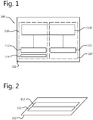
- a sensing device 100 according to an embodiment of the present invention is shown, wherein the sensing device 100 comprises at least one first sensor element 112 and a second sensor element 122 processed on the same chip, i.e. processed on the same substrate 102.
- the first sensor element 112 and second sensor element 122 and optional further sensor elements thus may be homogeneously or heterogeneously processed sensor elements, processed on the same substrate 102.
- the sensor elements are homogeneously processed sensor elements 112, 122 on the same substrate 102.
- the sensor elements 112, 122 may be integrated on the same substrate 102 whereby the different layers constituting the different sensor elements are processed for both sensor elements 112, 122 using the same processing technology, for example - but not limited to - CMOS processing technology.
- the sensor elements typically may comprise a plurality of pixels.
- the pixels typically may be arranged in a matrix form in a number of columns and rows, although the invention is not limited thereto.
- the sensor elements may be referred to as frame sensor elements, as the sensor elements are two dimensional sensor elements, comprising e.g. a matrix of sensor pixels m ⁇ n .
- the two sensor elements may be selected so that at least one of the number of pixels in a row or the number of pixels in a column is the same for both sensors.
- the sensor elements may comprise a high number of pixels in one direction for imaging simultaneously a relatively wide region of interest with a relatively high spatial resolution.
- a preferred scanning width may be at least 1000 m, more advantageously at least 2000 m, still more advantageously at least 3000 m.
- the number of pixels in one direction may in some examples be at least 1000, in other examples at least 4000, in still other examples 10000.
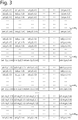
- FIG. 2 an example of a lay-out for the sensor elements 112, 122 on the substrate is shown in FIG. 2 .
- the sensor elements 112, 122 advantageously are surface aligned. The distance between the two sensors may be smaller than 1mm, although embodiments of the present invention are not limited thereby.
- the sensing device 100 furthermore comprises drive and read-out circuitry for driving the sensor elements 112, 122.
- the drive and read-out circuitry 130 may be adapted for driving the sensor elements 112, 122 differently from each other.
- the drive and read-out circuitry 130 may be a drive and read-out circuit as known from prior art, whereby the drive and read-out circuitry 130 may comprise components such as amplifiers, switches, a buss, etc.
- the pixel design, the column structure and the bus driver are laid out so that a multiplexer following the bus can be avoided, resulting in a better image quality.
- the drive and read-out circuitry also may be adapted for reading out the sensor elements 112,122. The read-out may be optimized for efficient and fast reading out.
- the frame rate at full resolution may be at least 35frames per second, e.g. at least 50 frames per second.
- the driving and reading out also may be performed by different components, i.e. a separate drive circuitry and separate reading-out circuitry may be provided.
- the sensors may be equipped with shutters so that fast shutting, e.g. electronic shutting, can be obtained.
- the sensor elements as well as the driving and read-out circuitry may be processed on the same chip or die using semiconductor processing, such as for example CMOS technology, embodiments of the invention not being limited thereto.
- the sensing device is adapted for providing different spectral information for different parts of a region of interest using the first two dimensional sensor element.
- the sensing device may thus be adapted for generating a multi-spectral image.
- the sensing device may be adapted for generating hyperspectral data, i.e. in many narrow spectral bands.
- the first sensor element is a two-dimensional sensor element and as different spectral information is to be captured, typically part of the sensor element may be used for obtaining spectral information at a first wavelength or in a first wavelength region for one part of the region of interest, and at least one other part of the sensor element may be used for obtaining spectral information at least a second wavelength or in at least a second wavelength region for at least another part of the region of interest.
- different lines of the sensor element may be used for gathering data at different spectral wavelengths or in different spectral wavelength regions.
- different blocks of the sensor element may be used for sensing different spectral data or different columns may be used for sensing different spectral data.
- a multi-spectral filter 114 may be present.
- the multi-spectral filter 114 forms together with the first sensor element 112 and the drive and read-out circuitry or part thereof for controlling the first sensor element 112, the first sensor.
- the multi-spectral filter may be directly applied to the first sensor element, e.g. mechanically behaving as a single element.
- the two components may be separate from each other, but configured or arranged so that appropriate filtering is obtained.
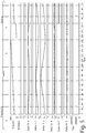
- FIG. 3 illustrates a plurality of subsequent hyperspectral images recorded in m subsequent time spans, whereby the spectra are recorded for a relative movement between region of interest and sensing or imaging system corresponding with a total shift over a distance xm - x1 travelled during the total of the subsequent time spans.
- FIG. 3 illustrates m hyperspectral images, each image consisting of m lines, wherein line L j comprises information of wavelength ⁇ j or e.g. of spectral band ⁇ j - ⁇ j -1 .
- the different images are recorded within m subsequent time frames.
- the imaging of a physical position at coordinates x p and y q of the region of interest is indicated throughout the different hyperspectral images. It can for example be seen that in the information regarding the physical position at coordinate x l for different y q coordinates of the region of interest is in the first hyperspectral image HI 1 found in line 1, in the second hyperspectral image HI 2 found in line 2, in the third hyperspectral image HI 3 found in line 3, ...
- the other lines of m subsequent hyperspectral images contain information regarding a region of interest at a different wavelength or in a different spectral band.
- the latter illustrates how hyperspectral images provide information regarding different spectral wavelengths or in different spectral bands and how subsequent hyperspectral images recorded during relative movement of region of interest and sensing system can provide an image of the full region of interest for different wavelengths or in different spectral bands.
- the principle is illustrated for subsequent lines covering different wavelengths, embodiments of the present invention are not limited thereto, and the variety of spectral information also may be obtained in other directions, e.g. varying spectral info for subsequent columns.
- each line corresponds with a different wavelength or spectral region
- embodiments of the present invention are not limited thereto and several lines of the spectral image may correspond with the same wavelength or spectral region. It is a characteristic of a spectral image that the image comprises information regarding at least two different wavelengths or spectral regions. Capturing of information using the principle as described above has the advantage that using a two dimensional sensor element, two dimensional images are recorded at different wavelengths or spectral regions, i.e. resulting in three dimensional information (two positional dimensions, one spectral dimension).
- the sensor element for spectral data may be used as a set of line or block sensing sub-elements each subelement recording positional information for a given wavelength or in a spectral region, whereby recording over time during relative movement of the region of interest with respect to the sensor element corresponds with scanning different positions of a region of interest.
- the sensing device 100 furthermore comprises a second two-dimensional sensor element 122 that forms, together with the driving and read-out circuitry or part thereof for driving the second two-dimensional sensor element 122 the second sensor 120.
- the second sensor 120 may be adapted for obtaining an image of the region of interest from which geo-referencing information can be obtained.
- the second sensor 120 may be adapted for providing a high resolution image, providing detailed geometric information, e.g. geographical information, regarding the region of interest. Images obtained via the second sensor 120 may allow to derive tie points in the imaged region of interest.
- the frequency at which the images are captured with the second sensor may be such that an overlap of the image, e.g. with at least 10%, more advantageously with at least 25%, still more advantageously with at least 50% such as e.g. with 60% overlap with the previous image is established, such that information regarding the relative change in orientation of the instrument between subsequent images can be detected.
- the obtained information regarding rotation may be used as geometric referencing information, according to embodiments of the present invention, for coupling to the multi-spectral data obtained using the first sensor 110, so that geo-referenced multi-spectral data can be obtained.
- the frequency at which the images are captured with the second sensor is lower than that at which images are captured with the first sensor.
- the image acquisition frequency of the second sensor is an integer fraction of the image acquisition frequency of the first sensor, such that images acquired with the first sensor periodically coincide in time with images acquired with the second sensor.
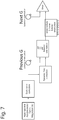
- interpolated geometric data has to be used for the images of the first sensor for which no synchronous image of the second sensor exists. This interpolated geometric data is obtained from the second-sensor images that are closest in acquisition time to the targeted first-sensor image, preferably the second-sensor images immediately preceding and immediately following the targeted first-sensor image. Such a difference in image acquisition frequencies is schematically illustrated in FIG. 5 .
- an interpolation algorithm is used which is specifically suited for platform attitude interpolation.
- the parameters to be interpolated include the various angles that describe the attitude of the sensing device. Accordingly, certain embodiments at least partially use interpolation of attitude data in angular coordinates.
- the interpolation algorithm uses first derivatives (angular and/or linear velocity) and second derivatives (angular and/or linear acceleration) to predict the attitude of the sensing device at moments between captured images, taking into account the laws of mechanics that govern the motion of the sensing device and the platform on which it is mounted (e.g., an aerial vehicle).
- first and second derivatives may be obtained from an inertial measurement unit (including GPS, gyroscopes, accelerometers, etc.).
- the purpose of the interpolation algorithm is to obtain accurate estimates on position and external orientation of the platform for every first sensor image (spectral image), on the basis of the (less frequently acquired) second sensor images.
- the inputs for this may be obtained from two independent sources:
- GPS for position
- IMU for attitude
- image data (high quality, high spatial resolution second sensor images).
- Dedicated points in the images are matched using features (ground control points). This can yield very accurate estimates of position and attitude for the time points for which there is a G-frame available.
- Embodiments of the present invention also relate to an imaging system.
- a schematic representation of an imaging system 200 comprising a sensing system according to embodiments of the present invention is shown in FIG. 4 by way of example.
- the imaging system 200 comprises a sensing device 100 as described for example above.
- the imaging system 200 furthermore comprises optical elements for guiding radiation to the two sensing elements of the sensing device 100.
- Such optical elements may for example comprise at least one lens 210 for capturing the radiation to be collected and focusing the radiation onto the sensor elements.
- a single lens 210 may be used for collecting the radiation for both sensor elements, whereas in other embodiments different lenses may be used for the different sensor elements.
- the collected radiation may be split to the two sensor elements using a radiation splitter, such as for example a beam splitter 220.
- a radiation splitter such as for example a beam splitter 220.
- the configuration of the sensor elements 112, 122 processed on the same substrate 102 may allow for taking into account positional information between the sensor elements when correlating the images obtained using the two sensor elements.
- the imaging system furthermore may comprise an image processor 230 for correlating the images obtained with the first sensor 110 and the second sensor 120.
- the image processor may for example correlate geometric information, e.g. positional information, obtained with the second sensor 120 with spectral information obtained in different spectral channels in the first sensor 110, so that accurate hyperspectral information is obtained.
- Such image processing may be performed in a single processor or in a plurality of processors. The processing may be performed after the full set of images have been captured, although in some embodiments substantially direct processing may be performed, as soon as all information regarding the same region of interest is captured in both sensors 110, 120.
- a more detailed description of the image processing that may be performed by a processor 230 according to embodiments of the present invention will further be discussed later with reference to FIG. 6 , illustrating standard and optional steps of an example of a method for sensing according to an embodiment of the present invention.
- the imaging device furthermore may comprise a global positioning system for providing GPS data and/or an inertial measurement unit for providing inertial data regarding the imaging system.
- a global positioning system for providing GPS data and/or an inertial measurement unit for providing inertial data regarding the imaging system.
- Such components may assist in providing approximate geo-referencing data, which may assist in deriving geo-referenced spectral-data based on the image obtained with the second sensor 120.
- the present invention thus also relates to an imaging system as described above comprising a sensing device as described above.
- the present invention also relates to an industrial system or unmanned aerial vehicle (UAV) comprising such an imaging system for monitoring, imaging or inspection.
- UAV unmanned aerial vehicle
- the sensing device comprises the two sensing elements on the same sensor, such that thermal load due to temperature variation or such that environmental conditions have less influence on the obtained result.
- the present invention relates to a method for obtaining image data regarding a region of interest. It thereby is an advantage of embodiments according to the present invention that multi-spectral data of a region of interest can be obtained with high geometric accuracy, e.g. geographic accuracy, e.g.
- the method is especially suitable in applications where multi-spectral data of a region of interest are obtained using sensing device that undergo a relative movement with respect to the region of interest, such as for example in case aerial imaging is performed or e.g. during industrial inspection of moving products.
- the method furthermore also is especially suitable for use in unmanned aerial vehicles (UAV), as the method can be performed using components low in weight, which is a major requirement if unmanned aerial vehicles are to be used or are to be used for a longer time. More particularly, the lower the weight to be carried, the lower the power consumption required and the longer flying times can be obtained with the unmanned aerial vehicles.
- UAV unmanned aerial vehicles
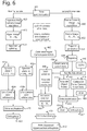
- FIG. 6 illustrates a detailed flow chart of an exemplary method for obtaining image data.
- the exemplary method thereby is adapted for capturing at least one two-dimensional image of the region of interest for deriving geometric referencing information, and for capturing hyperspectral images using a system as described above. More particularly, in the present example, the different hyperspectral images are obtained during relative movement of the region of interest with respect to the imaging system.
- the hyperspectral images are taken at a higher rate than the geometric reference images, which rates are preferably integer multiples and may be derived from a common synchronization block 405.
- image acquisition for obtaining a two dimensional image of a region of interest is performed in step 430.
- image acquisition includes acquisition of a set of frame images FI 1 , FI 2 , ... FI n , whereby n images are captured, as indicated in step 432.
- the images advantageously have a significant overlap so that geometric information, e.g. geographic information, on one image can be transferred to a subsequently or previously captured image and so that relative orientation changes can be detected.
- the overlap typically may be selected in the order of 60%, although embodiments of the present invention are not limited thereto. From the overlap of at least two images, tie points can be generated, as indicated in step 434.
- tie points are points occurring in the overlap of the images and thus allowing to determine a change in orientation of the instrument between acquisition of subsequent images.
- some ground control points may be available, providing geographical information indicating a geographical correlation between objects in the region of interest and their image in the two dimensional image, e.g. via GPS, via a list of previously recorded images, etc.
- the method may comprise a calibration step, wherein bundle adjustment is performed as indicated in 442, based on the generated tie points, indicated in 438, on global positioning coordinates, indicated in 440 and on initial camera parameters 436.
- This post processing step allows to obtain a more accurate exterior orientation, as indicated in 444, and which then can be used for obtaining corrected frame images having an accurate exterior orientation, as indicated in step 460.
- accurate object points and frame camera parameters can be used. Accurate object points and accurate calibration frame camera parameters as well as standard Digital Elevation Model (DEM) products can be obtained as indicated in steps 446, 448, 480.
- DEM Digital Elevation Model
- spectral camera image acquisition e.g. hyper-spectral camera image acquisition is performed in step 410, resulting in a set of spectral images as indicated in step 412, whereby, in the present example each spectral image consists of a plurality of lines and each line contains information of a particular spectral band.
- the full spectral information regarding a region of interest for a given wavelength or in a given wavelength region is distributed over different, typically subsequently imaged, hyper-spectral images and using spectral splitting as indicated by 414, spectral plane information is obtained for the full region of interest as indicated in steps 416a, 416b.
- geometric-referenced multi-spectral information can be obtained by coupling the geometric-referencing information including e.g. orientational information, to the spectral plane data, optionally including calibrated hyper-spectral camera parameters as indicated in 462. The latter results in geometric-referenced spectral information, as shown in 418a, 418b.
- the aforementioned interpolation step takes place prior to the geometric-referencing 462, i.e. at the stage 444.
- the interpolation is schematically illustrated in the more detailed flow chart in FIG. 7 .
- an orthorectification of the images may be performed as indicated in steps 420 and 450 for the multi-spectral and conventional 2-dimensional image respectively, resulting in an orthophoto for both the multi-spectral and conventional 2-dimensional image, as indicated in steps 422 and 452 respectively.
- Orthorectification means terrain corrected geometric referencing of imagery using for example the sensor exterior orientation parameters, frame camera parameters (also referred to as interior orientation) and standard Digital Elevation Model (DEM) products.
- the result of this operation is an orthophoto.
- Combining these orthophoto images allows performing PAN sharpening of the multi-spectral data, as indicated in step 470, such that a PAN sharpened hyperspectral orthophoto can be obtained, as indicated in step 472.
- the orthorectification of the conventional 2-dimensional image may give rise to a digital surface model, as indicated in step 454.
- This preliminary renormalization step may comprise dividing spectral images in identically arranged areas; for each of the areas, calculating a predetermined characteristic across said set of images; and, for each of the images, renormalizing intensity values in each of the areas in function of the predetermined characteristic of said area.
- This preliminary renormalization step may comprise dividing spectral images in identically arranged areas; for each of the areas, calculating a predetermined characteristic across said set of images; and, for each of the images, renormalizing intensity values in each of the areas in function of the predetermined characteristic of said area.
- For the said areas one or more representative characteristics of the intensity values can be calculated.
- the average intensity value over the area is one such characteristic.
- Another useful characteristic is the standard deviation of the intensity values, which gives an indication of the contrast which will be measured. More generally, the distribution of the intensity values could be calculated and represented in a larger set of characteristics.
- the set of obtained characteristics per area can be used as normalization coefficients. After applying normalization using the characteristics, the values of
- the procedure to determine the normalization coefficients is carried out by averaging over a sufficiently large set of images, in order to average out the effect of the image content. Afterwards, the normalization can be carried out using the established coefficients, either on the same images, or on other images acquired in a similar way with the same instrument. This procedure simplifies the way of working as it is not necessary to calculate new coefficients for every new set of images.
- pre-processing is inter alia based on the insight of the inventors that there are two components to the difference in intensity of a given physical feature between different spectral images of the same acquisition series, which represent the physical feature in different wavelength bands: (1) the physical feature may have a different reflectivity in different wavelength bands and (2) the sensor may have a different sensitivity in different wavelength bands.
- the second factor can be compensated by renormalizing the various parts of the images relative to an average value that is representative for each respective part. While it is not possible to compensate for the first factor, the inventors have surprisingly found that the efficiency of registration algorithms and the like already greatly improves after compensating the second factor alone. The effect is believed to be due to the fact that real-world physical objects typically exhibit a slowly varying reflectivity in function of wavelength over a large part of the spectrum of interest.
- the predetermined characteristic may be an average intensity
- the renormalizing may comprise renormalizing the intensity values in each of the areas relative to the average intensity value.
- the areas may correspond to individual pixels. It is an advantage of this embodiment that the sensor is effectively calibrated on a per-pixel basis, such that variations in sensitivity of individual pixel-filter combinations can be accounted for, regardless of the source of such variations (including manufacturing tolerances or impurities in the filter). This leads to a maximal suppression of artefacts.
- an optical system By adding an optical system to the pixel-filter combinations, a complete imaging system is obtained. It can be chosen to include sensitivity variations caused by the optical system to correct for those, or to exclude them so that the system remains generic for different optical systems.
- the areas may correspond to distinct wavelength bands. It is an advantage of this embodiment that the renormalization can be performed per block of pixels, wherein a block typically represents a rectangular strip of the sensor or a combination of multiple rectangular areas.
- embodiments of the present invention are not limited thereto and may for example also be used for industrial inspection etc.
- a sensing device can for example be used for inspecting goods on a conveyor belt, e.g. for detecting foreign materials between goods or for detecting deviating goods. Such foreign materials or deviating goods typically will show a spectral image deviating from the expected spectral image.
- the geometric referencing information may be a lateral position of objects or materials but also may be a height or relative height.
- Such a height or relative height of objects may for example be determined from the geometric referencing information based on the viewing angle of the geometric referencing sensor with respect to the object imaged. Deriving height information from image data based on a known sensor position and viewing angle with respect to the overall region of interest to be imaged is known by persons skilled in the art.
- the present invention also relates to a processing system wherein the method for sensing or imaging or part of such method as described in embodiments of the previous aspects are implemented in a software based manner.
- a processing system may include at least one programmable processor coupled to a memory subsystem that includes at least one form of memory, e.g., RAM, ROM, and so forth.
- the processor or processors may be a general purpose, or a special purpose processor, and may be for inclusion in a device, e.g., a chip that has other components that perform other functions.
- one or more aspects of embodiments of the present invention can be implemented in digital electronic circuitry, or in computer hardware, firmware, software, or in combinations of them.
- the processing system may include a storage subsystem that has at least one disk drive and/or CD-ROM drive and/or DVD drive.
- a display system, a keyboard, and a pointing device may be included as part of a user interface subsystem to provide for a user to manually input information. Ports for inputting and outputting data also may be included. More elements such as network connections, interfaces to various devices, and so forth, may be included.
- the various elements of the processing system may be coupled in various ways, including via a bus subsystem.
- the memory of the memory subsystem may at some time hold part or all of a set of instructions that when executed on the processing system implement the steps of the method embodiments described herein.
- the present invention also includes a computer program product which provides the functionality of any of the methods according to the present invention when executed on a computing device.
- Such computer program product can be tangibly embodied in a carrier medium carrying machine-readable code for execution by a programmable processor.
- the present invention thus relates to a carrier medium carrying a computer program product that, when executed on computing means, provides instructions for executing any of the methods as described above.
- carrier medium refers to any medium that participates in providing instructions to a processor for execution. Such a medium may take many forms, including but not limited to, non-volatile media, and transmission media.
- Non volatile media includes, for example, optical or magnetic disks, such as a storage device which is part of mass storage.
- Computer readable media include, a CD-ROM, a DVD, a flexible disk or floppy disk, a tape, a memory chip or cartridge or any other medium from which a computer can read.
- Various forms of computer readable media may be involved in carrying one or more sequences of one or more instructions to a processor for execution.
- the computer program product can also be transmitted via a carrier wave in a network, such as a LAN, a WAN or the Internet.
- Transmission media can take the form of acoustic or light waves, such as those generated during radio wave and infrared data communications. Transmission media include coaxial cables, copper wire and fiber optics, including the wires that comprise a bus within a computer.
- a single processor or other unit may fulfill the functions of several items recited in the claims.
- the mere fact that certain measures are recited in mutually different dependent claims does not indicate that a combination of these measures cannot be used to advantage.
- a computer program may be stored/distributed on a suitable medium, such as an optical storage medium or a solid-state medium supplied together with or as part of other hardware, but may also be distributed in other forms, such as via the Internet or other wired or wireless telecommunication systems. Any reference signs in the claims should not be construed as limiting the scope.
Landscapes
- Engineering & Computer Science (AREA)
- Multimedia (AREA)
- Signal Processing (AREA)
- Physics & Mathematics (AREA)
- General Physics & Mathematics (AREA)
- Radar, Positioning & Navigation (AREA)
- Remote Sensing (AREA)
- Spectroscopy & Molecular Physics (AREA)
- Image Processing (AREA)
- Spectrometry And Color Measurement (AREA)
- Investigating Or Analysing Materials By Optical Means (AREA)
- Aviation & Aerospace Engineering (AREA)
- Geophysics And Detection Of Objects (AREA)
- Image Input (AREA)
- Image Analysis (AREA)
Priority Applications (1)
| Application Number | Priority Date | Filing Date | Title |
|---|---|---|---|
| PL15741955T PL3167242T3 (pl) | 2014-07-07 | 2015-07-07 | Sposób i układ do ustalania geometrii odniesienia dla danych wielospektralnych |
Applications Claiming Priority (3)
| Application Number | Priority Date | Filing Date | Title |
|---|---|---|---|
| US201462021292P | 2014-07-07 | 2014-07-07 | |
| GBGB1412061.2A GB201412061D0 (en) | 2014-07-07 | 2014-07-07 | Method and system for geometric referencing of multi-spectral data |
| PCT/EP2015/065523 WO2016005411A1 (en) | 2014-07-07 | 2015-07-07 | Method and system for geometric referencing of multi-spectral data |
Publications (2)
| Publication Number | Publication Date |
|---|---|
| EP3167242A1 EP3167242A1 (en) | 2017-05-17 |
| EP3167242B1 true EP3167242B1 (en) | 2018-09-26 |
Family
ID=51410739
Family Applications (1)
| Application Number | Title | Priority Date | Filing Date |
|---|---|---|---|
| EP15741955.7A Not-in-force EP3167242B1 (en) | 2014-07-07 | 2015-07-07 | Method and system for geometric referencing of multi-spectral data |
Country Status (12)
| Country | Link |
|---|---|
| US (1) | US10054438B2 (enExample) |
| EP (1) | EP3167242B1 (enExample) |
| JP (1) | JP6573959B2 (enExample) |
| CN (1) | CN106537089B (enExample) |
| AU (1) | AU2015286734A1 (enExample) |
| CA (1) | CA2954348A1 (enExample) |
| ES (1) | ES2702932T3 (enExample) |
| GB (1) | GB201412061D0 (enExample) |
| PL (1) | PL3167242T3 (enExample) |
| PT (1) | PT3167242T (enExample) |
| TR (1) | TR201818857T4 (enExample) |
| WO (1) | WO2016005411A1 (enExample) |
Cited By (1)
| Publication number | Priority date | Publication date | Assignee | Title |
|---|---|---|---|---|
| EP4370871A4 (en) * | 2021-07-12 | 2025-05-21 | Galaxeye Space Solutions Private Limited | A system and method for sensing topology of a planet |
Families Citing this family (15)
| Publication number | Priority date | Publication date | Assignee | Title |
|---|---|---|---|---|
| PL3193136T3 (pl) | 2016-01-13 | 2019-12-31 | Vito Nv | Sposób i system odniesienia geometrycznego danych wielospektralnych |
| US10189567B2 (en) * | 2016-06-09 | 2019-01-29 | Skycatch, Inc. | Identifying camera position of a UAV in flight utilizing real time kinematic satellite navigation |
| US10656305B2 (en) * | 2016-07-01 | 2020-05-19 | The Boeing Company | Method and apparatus for simulating spectral information of geographic areas |
| US10621780B2 (en) * | 2017-02-02 | 2020-04-14 | Infatics, Inc. | System and methods for improved aerial mapping with aerial vehicles |
| EP3664029B1 (en) * | 2017-08-01 | 2023-12-13 | Sony Group Corporation | Image processing device, image processing method, and program |
| KR102500640B1 (ko) * | 2018-03-02 | 2023-02-15 | 제이에프이 스틸 가부시키가이샤 | 로의 제어 방법 |
| CN113226007B (zh) * | 2018-12-03 | 2023-04-14 | 迈卡赛斯公司 | 图像传感器和热像仪设备及其系统和方法 |
| EP3667617A1 (en) * | 2018-12-14 | 2020-06-17 | Koninklijke Philips N.V. | Imaging system and imaging method |
| US11245875B2 (en) * | 2019-01-15 | 2022-02-08 | Microsoft Technology Licensing, Llc | Monitoring activity with depth and multi-spectral camera |
| US10666878B1 (en) | 2019-04-09 | 2020-05-26 | Eagle Technology, Llc | Imaging apparatus having micro-electro-mechanical system (MEMs) optical device for spectral and temporal imaging and associated methods |
| CN111017212A (zh) * | 2019-11-26 | 2020-04-17 | 郑州信息科技职业学院 | 一种多旋翼无人机多光谱遥感系统 |
| MX2022006769A (es) * | 2019-12-02 | 2022-08-22 | Click Ins Ltd | Sistemas, métodos y programas para generar una impresión de daño en un vehículo. |
| CN113433081B (zh) * | 2021-07-06 | 2022-05-24 | 江南大学 | 基于动态神经网络的果蔬干燥过程中品质检测方法及系统 |
| AU2022439107A1 (en) | 2022-02-01 | 2024-09-19 | Landscan Llc | Systems and methods for multispectral landscape mapping |
| CN115639159B (zh) * | 2022-12-08 | 2023-04-11 | 航天宏图信息技术股份有限公司 | 一种基于多光谱影像的废水污染监测方法和装置 |
Family Cites Families (7)
| Publication number | Priority date | Publication date | Assignee | Title |
|---|---|---|---|---|
| US6211906B1 (en) | 1995-09-07 | 2001-04-03 | Flight Landata, Inc. | Computerized component variable interference filter imaging spectrometer system method and apparatus |
| US8174694B2 (en) * | 2001-12-21 | 2012-05-08 | Bodkin Design And Engineering Llc | Hyperspectral imaging systems |
| US6831688B2 (en) * | 2002-04-08 | 2004-12-14 | Recon/Optical, Inc. | Multispectral or hyperspectral imaging system and method for tactical reconnaissance |
| WO2011073430A1 (en) | 2009-12-18 | 2011-06-23 | Vito Nv (Vlaamse Instelling Voor Technologisch Onderzoek) | Geometric referencing of multi-spectral data |
| DE102010041569B4 (de) * | 2010-09-28 | 2017-04-06 | Leica Geosystems Ag | Digitales Kamerasystem, Farbfilterelement für digitales Kamerasystem, Verfahren zur Bestimmung von Abweichungen zwischen den Kameras eines digitalen Kamerasystems sowie Bildverarbeitungseinheit für digitales Kamerasystem |
| JP5787695B2 (ja) | 2011-09-28 | 2015-09-30 | 株式会社トプコン | 画像取得装置 |
| CN102967376B (zh) * | 2012-11-20 | 2014-10-15 | 中国科学院西安光学精密机械研究所 | 一种高频图像序列的获取方法及其采用的分时分光装置 |
-
2014
- 2014-07-07 GB GBGB1412061.2A patent/GB201412061D0/en not_active Ceased
-
2015
- 2015-07-07 PT PT15741955T patent/PT3167242T/pt unknown
- 2015-07-07 CN CN201580037455.3A patent/CN106537089B/zh not_active Expired - Fee Related
- 2015-07-07 TR TR2018/18857T patent/TR201818857T4/tr unknown
- 2015-07-07 CA CA2954348A patent/CA2954348A1/en not_active Abandoned
- 2015-07-07 AU AU2015286734A patent/AU2015286734A1/en not_active Abandoned
- 2015-07-07 JP JP2017500990A patent/JP6573959B2/ja not_active Expired - Fee Related
- 2015-07-07 US US15/322,384 patent/US10054438B2/en not_active Expired - Fee Related
- 2015-07-07 PL PL15741955T patent/PL3167242T3/pl unknown
- 2015-07-07 WO PCT/EP2015/065523 patent/WO2016005411A1/en not_active Ceased
- 2015-07-07 EP EP15741955.7A patent/EP3167242B1/en not_active Not-in-force
- 2015-07-07 ES ES15741955T patent/ES2702932T3/es active Active
Non-Patent Citations (1)
| Title |
|---|
| None * |
Cited By (1)
| Publication number | Priority date | Publication date | Assignee | Title |
|---|---|---|---|---|
| EP4370871A4 (en) * | 2021-07-12 | 2025-05-21 | Galaxeye Space Solutions Private Limited | A system and method for sensing topology of a planet |
Also Published As
| Publication number | Publication date |
|---|---|
| CN106537089B (zh) | 2020-03-31 |
| US20170138733A1 (en) | 2017-05-18 |
| US10054438B2 (en) | 2018-08-21 |
| WO2016005411A1 (en) | 2016-01-14 |
| JP6573959B2 (ja) | 2019-09-11 |
| JP2017522666A (ja) | 2017-08-10 |
| PL3167242T3 (pl) | 2019-04-30 |
| CN106537089A (zh) | 2017-03-22 |
| EP3167242A1 (en) | 2017-05-17 |
| AU2015286734A1 (en) | 2016-12-22 |
| GB201412061D0 (en) | 2014-08-20 |
| PT3167242T (pt) | 2018-12-24 |
| CA2954348A1 (en) | 2016-01-14 |
| ES2702932T3 (es) | 2019-03-06 |
| TR201818857T4 (tr) | 2019-01-21 |
Similar Documents
| Publication | Publication Date | Title |
|---|---|---|
| EP3167242B1 (en) | Method and system for geometric referencing of multi-spectral data | |
| EP2513599B1 (en) | Geometric referencing of multi-spectral data | |
| EP3167432B1 (en) | Method and system for photogrammetric processing of images | |
| EP3193136B1 (en) | Method and system for geometric referencing of multi-spectral data | |
| Jhan et al. | Robust and adaptive band-to-band image transform of UAS miniature multi-lens multispectral camera | |
| Haavardsholm et al. | Multimodal Multispectral Imaging System for Small UAVs | |
| Delauré et al. | The geospectral camera: a compact and geometrically precise hyperspectral and high spatial resolution imager | |
| Berveglieri et al. | Bundle adjustment of a time-sequential spectral camera using polynomial models | |
| Inamdar | Towards the Improvement of Hyperspectral Imaging Data: Limitations of the Raster Model and the Development of a Novel Point Cloud Data Format | |
| Yang | Enhancing positional accuracy of airborne hyperspectral imagery with concurrent RGB images | |
| Altangerel et al. | Analysis of remote sensing based vegetation indices (VIs) for unmanned aerial system (UAS) | |
| CN105487083A (zh) | 一种多光谱影像气溶胶像元气溶胶厚度的检测与提取方法 | |
| Haala | On the performance of digital airborne pushbroom cameras for photogrammetric data processing-a case study |
Legal Events
| Date | Code | Title | Description |
|---|---|---|---|
| STAA | Information on the status of an ep patent application or granted ep patent |
Free format text: STATUS: THE INTERNATIONAL PUBLICATION HAS BEEN MADE |
|
| PUAI | Public reference made under article 153(3) epc to a published international application that has entered the european phase |
Free format text: ORIGINAL CODE: 0009012 |
|
| STAA | Information on the status of an ep patent application or granted ep patent |
Free format text: STATUS: REQUEST FOR EXAMINATION WAS MADE |
|
| 17P | Request for examination filed |
Effective date: 20170201 |
|
| AK | Designated contracting states |
Kind code of ref document: A1 Designated state(s): AL AT BE BG CH CY CZ DE DK EE ES FI FR GB GR HR HU IE IS IT LI LT LU LV MC MK MT NL NO PL PT RO RS SE SI SK SM TR |
|
| AX | Request for extension of the european patent |
Extension state: BA ME |
|
| DAV | Request for validation of the european patent (deleted) | ||
| DAX | Request for extension of the european patent (deleted) | ||
| REG | Reference to a national code |
Ref country code: DE Ref legal event code: R079 Ref document number: 602015017042 Country of ref document: DE Free format text: PREVIOUS MAIN CLASS: G01C0011020000 Ipc: B64C0039020000 |
|
| GRAP | Despatch of communication of intention to grant a patent |
Free format text: ORIGINAL CODE: EPIDOSNIGR1 |
|
| STAA | Information on the status of an ep patent application or granted ep patent |
Free format text: STATUS: GRANT OF PATENT IS INTENDED |
|
| RIC1 | Information provided on ipc code assigned before grant |
Ipc: G01J 3/28 20060101ALI20180405BHEP Ipc: G01C 11/02 20060101ALI20180405BHEP Ipc: H04N 5/33 20060101ALI20180405BHEP Ipc: H04N 7/12 20060101ALI20180405BHEP Ipc: B64C 39/02 20060101AFI20180405BHEP Ipc: B64D 47/08 20060101ALI20180405BHEP Ipc: H04N 7/18 20060101ALI20180405BHEP |
|
| INTG | Intention to grant announced |
Effective date: 20180503 |
|
| GRAS | Grant fee paid |
Free format text: ORIGINAL CODE: EPIDOSNIGR3 |
|
| GRAA | (expected) grant |
Free format text: ORIGINAL CODE: 0009210 |
|
| STAA | Information on the status of an ep patent application or granted ep patent |
Free format text: STATUS: THE PATENT HAS BEEN GRANTED |
|
| AK | Designated contracting states |
Kind code of ref document: B1 Designated state(s): AL AT BE BG CH CY CZ DE DK EE ES FI FR GB GR HR HU IE IS IT LI LT LU LV MC MK MT NL NO PL PT RO RS SE SI SK SM TR |
|
| REG | Reference to a national code |
Ref country code: GB Ref legal event code: FG4D |
|
| REG | Reference to a national code |
Ref country code: CH Ref legal event code: EP |
|
| REG | Reference to a national code |
Ref country code: AT Ref legal event code: REF Ref document number: 1045697 Country of ref document: AT Kind code of ref document: T Effective date: 20181015 |
|
| REG | Reference to a national code |
Ref country code: IE Ref legal event code: FG4D |
|
| REG | Reference to a national code |
Ref country code: DE Ref legal event code: R096 Ref document number: 602015017042 Country of ref document: DE |
|
| REG | Reference to a national code |
Ref country code: PT Ref legal event code: SC4A Ref document number: 3167242 Country of ref document: PT Date of ref document: 20181224 Kind code of ref document: T Free format text: AVAILABILITY OF NATIONAL TRANSLATION Effective date: 20181217 |
|
| REG | Reference to a national code |
Ref country code: NL Ref legal event code: FP |
|
| PG25 | Lapsed in a contracting state [announced via postgrant information from national office to epo] |
Ref country code: GR Free format text: LAPSE BECAUSE OF FAILURE TO SUBMIT A TRANSLATION OF THE DESCRIPTION OR TO PAY THE FEE WITHIN THE PRESCRIBED TIME-LIMIT Effective date: 20181227 Ref country code: SE Free format text: LAPSE BECAUSE OF FAILURE TO SUBMIT A TRANSLATION OF THE DESCRIPTION OR TO PAY THE FEE WITHIN THE PRESCRIBED TIME-LIMIT Effective date: 20180926 Ref country code: LT Free format text: LAPSE BECAUSE OF FAILURE TO SUBMIT A TRANSLATION OF THE DESCRIPTION OR TO PAY THE FEE WITHIN THE PRESCRIBED TIME-LIMIT Effective date: 20180926 Ref country code: FI Free format text: LAPSE BECAUSE OF FAILURE TO SUBMIT A TRANSLATION OF THE DESCRIPTION OR TO PAY THE FEE WITHIN THE PRESCRIBED TIME-LIMIT Effective date: 20180926 Ref country code: RS Free format text: LAPSE BECAUSE OF FAILURE TO SUBMIT A TRANSLATION OF THE DESCRIPTION OR TO PAY THE FEE WITHIN THE PRESCRIBED TIME-LIMIT Effective date: 20180926 Ref country code: BG Free format text: LAPSE BECAUSE OF FAILURE TO SUBMIT A TRANSLATION OF THE DESCRIPTION OR TO PAY THE FEE WITHIN THE PRESCRIBED TIME-LIMIT Effective date: 20181226 |
|
| REG | Reference to a national code |
Ref country code: LT Ref legal event code: MG4D |
|
| REG | Reference to a national code |
Ref country code: NO Ref legal event code: T2 Effective date: 20180926 |
|
| PG25 | Lapsed in a contracting state [announced via postgrant information from national office to epo] |
Ref country code: AL Free format text: LAPSE BECAUSE OF FAILURE TO SUBMIT A TRANSLATION OF THE DESCRIPTION OR TO PAY THE FEE WITHIN THE PRESCRIBED TIME-LIMIT Effective date: 20180926 Ref country code: LV Free format text: LAPSE BECAUSE OF FAILURE TO SUBMIT A TRANSLATION OF THE DESCRIPTION OR TO PAY THE FEE WITHIN THE PRESCRIBED TIME-LIMIT Effective date: 20180926 Ref country code: HR Free format text: LAPSE BECAUSE OF FAILURE TO SUBMIT A TRANSLATION OF THE DESCRIPTION OR TO PAY THE FEE WITHIN THE PRESCRIBED TIME-LIMIT Effective date: 20180926 |
|
| REG | Reference to a national code |
Ref country code: ES Ref legal event code: FG2A Ref document number: 2702932 Country of ref document: ES Kind code of ref document: T3 Effective date: 20190306 |
|
| REG | Reference to a national code |
Ref country code: AT Ref legal event code: MK05 Ref document number: 1045697 Country of ref document: AT Kind code of ref document: T Effective date: 20180926 |
|
| PG25 | Lapsed in a contracting state [announced via postgrant information from national office to epo] |
Ref country code: EE Free format text: LAPSE BECAUSE OF FAILURE TO SUBMIT A TRANSLATION OF THE DESCRIPTION OR TO PAY THE FEE WITHIN THE PRESCRIBED TIME-LIMIT Effective date: 20180926 Ref country code: RO Free format text: LAPSE BECAUSE OF FAILURE TO SUBMIT A TRANSLATION OF THE DESCRIPTION OR TO PAY THE FEE WITHIN THE PRESCRIBED TIME-LIMIT Effective date: 20180926 Ref country code: AT Free format text: LAPSE BECAUSE OF FAILURE TO SUBMIT A TRANSLATION OF THE DESCRIPTION OR TO PAY THE FEE WITHIN THE PRESCRIBED TIME-LIMIT Effective date: 20180926 Ref country code: CZ Free format text: LAPSE BECAUSE OF FAILURE TO SUBMIT A TRANSLATION OF THE DESCRIPTION OR TO PAY THE FEE WITHIN THE PRESCRIBED TIME-LIMIT Effective date: 20180926 Ref country code: IS Free format text: LAPSE BECAUSE OF FAILURE TO SUBMIT A TRANSLATION OF THE DESCRIPTION OR TO PAY THE FEE WITHIN THE PRESCRIBED TIME-LIMIT Effective date: 20190126 |
|
| PG25 | Lapsed in a contracting state [announced via postgrant information from national office to epo] |
Ref country code: SK Free format text: LAPSE BECAUSE OF FAILURE TO SUBMIT A TRANSLATION OF THE DESCRIPTION OR TO PAY THE FEE WITHIN THE PRESCRIBED TIME-LIMIT Effective date: 20180926 Ref country code: SM Free format text: LAPSE BECAUSE OF FAILURE TO SUBMIT A TRANSLATION OF THE DESCRIPTION OR TO PAY THE FEE WITHIN THE PRESCRIBED TIME-LIMIT Effective date: 20180926 |
|
| REG | Reference to a national code |
Ref country code: DE Ref legal event code: R097 Ref document number: 602015017042 Country of ref document: DE |
|
| PG25 | Lapsed in a contracting state [announced via postgrant information from national office to epo] |
Ref country code: DK Free format text: LAPSE BECAUSE OF FAILURE TO SUBMIT A TRANSLATION OF THE DESCRIPTION OR TO PAY THE FEE WITHIN THE PRESCRIBED TIME-LIMIT Effective date: 20180926 |
|
| PGFP | Annual fee paid to national office [announced via postgrant information from national office to epo] |
Ref country code: IT Payment date: 20190628 Year of fee payment: 5 Ref country code: NL Payment date: 20190628 Year of fee payment: 5 Ref country code: LU Payment date: 20190628 Year of fee payment: 5 |
|
| PLBE | No opposition filed within time limit |
Free format text: ORIGINAL CODE: 0009261 |
|
| STAA | Information on the status of an ep patent application or granted ep patent |
Free format text: STATUS: NO OPPOSITION FILED WITHIN TIME LIMIT |
|
| PGFP | Annual fee paid to national office [announced via postgrant information from national office to epo] |
Ref country code: BE Payment date: 20190628 Year of fee payment: 5 Ref country code: FR Payment date: 20190628 Year of fee payment: 5 |
|
| 26N | No opposition filed |
Effective date: 20190627 |
|
| PG25 | Lapsed in a contracting state [announced via postgrant information from national office to epo] |
Ref country code: SI Free format text: LAPSE BECAUSE OF FAILURE TO SUBMIT A TRANSLATION OF THE DESCRIPTION OR TO PAY THE FEE WITHIN THE PRESCRIBED TIME-LIMIT Effective date: 20180926 |
|
| PGFP | Annual fee paid to national office [announced via postgrant information from national office to epo] |
Ref country code: GB Payment date: 20190628 Year of fee payment: 5 Ref country code: PT Payment date: 20190703 Year of fee payment: 5 Ref country code: ES Payment date: 20190807 Year of fee payment: 5 Ref country code: DE Payment date: 20190628 Year of fee payment: 5 Ref country code: NO Payment date: 20190726 Year of fee payment: 5 |
|
| PGFP | Annual fee paid to national office [announced via postgrant information from national office to epo] |
Ref country code: PL Payment date: 20190701 Year of fee payment: 5 |
|
| PGFP | Annual fee paid to national office [announced via postgrant information from national office to epo] |
Ref country code: CH Payment date: 20190722 Year of fee payment: 5 |
|
| PG25 | Lapsed in a contracting state [announced via postgrant information from national office to epo] |
Ref country code: MC Free format text: LAPSE BECAUSE OF FAILURE TO SUBMIT A TRANSLATION OF THE DESCRIPTION OR TO PAY THE FEE WITHIN THE PRESCRIBED TIME-LIMIT Effective date: 20180926 |
|
| PG25 | Lapsed in a contracting state [announced via postgrant information from national office to epo] |
Ref country code: IE Free format text: LAPSE BECAUSE OF NON-PAYMENT OF DUE FEES Effective date: 20190707 |
|
| REG | Reference to a national code |
Ref country code: DE Ref legal event code: R119 Ref document number: 602015017042 Country of ref document: DE |
|
| REG | Reference to a national code |
Ref country code: CH Ref legal event code: PL |
|
| REG | Reference to a national code |
Ref country code: NO Ref legal event code: MMEP |
|
| REG | Reference to a national code |
Ref country code: NL Ref legal event code: MM Effective date: 20200801 |
|
| GBPC | Gb: european patent ceased through non-payment of renewal fee |
Effective date: 20200707 |
|
| REG | Reference to a national code |
Ref country code: BE Ref legal event code: MM Effective date: 20200731 |
|
| PG25 | Lapsed in a contracting state [announced via postgrant information from national office to epo] |
Ref country code: PT Free format text: LAPSE BECAUSE OF NON-PAYMENT OF DUE FEES Effective date: 20210208 Ref country code: FR Free format text: LAPSE BECAUSE OF NON-PAYMENT OF DUE FEES Effective date: 20200731 Ref country code: LI Free format text: LAPSE BECAUSE OF NON-PAYMENT OF DUE FEES Effective date: 20200731 Ref country code: NO Free format text: LAPSE BECAUSE OF NON-PAYMENT OF DUE FEES Effective date: 20200731 Ref country code: NL Free format text: LAPSE BECAUSE OF NON-PAYMENT OF DUE FEES Effective date: 20200801 Ref country code: LU Free format text: LAPSE BECAUSE OF NON-PAYMENT OF DUE FEES Effective date: 20200707 Ref country code: GB Free format text: LAPSE BECAUSE OF NON-PAYMENT OF DUE FEES Effective date: 20200707 Ref country code: CH Free format text: LAPSE BECAUSE OF NON-PAYMENT OF DUE FEES Effective date: 20200731 |
|
| PG25 | Lapsed in a contracting state [announced via postgrant information from national office to epo] |
Ref country code: DE Free format text: LAPSE BECAUSE OF NON-PAYMENT OF DUE FEES Effective date: 20210202 Ref country code: CY Free format text: LAPSE BECAUSE OF FAILURE TO SUBMIT A TRANSLATION OF THE DESCRIPTION OR TO PAY THE FEE WITHIN THE PRESCRIBED TIME-LIMIT Effective date: 20180926 Ref country code: BE Free format text: LAPSE BECAUSE OF NON-PAYMENT OF DUE FEES Effective date: 20200731 |
|
| PG25 | Lapsed in a contracting state [announced via postgrant information from national office to epo] |
Ref country code: MT Free format text: LAPSE BECAUSE OF FAILURE TO SUBMIT A TRANSLATION OF THE DESCRIPTION OR TO PAY THE FEE WITHIN THE PRESCRIBED TIME-LIMIT Effective date: 20180926 Ref country code: HU Free format text: LAPSE BECAUSE OF FAILURE TO SUBMIT A TRANSLATION OF THE DESCRIPTION OR TO PAY THE FEE WITHIN THE PRESCRIBED TIME-LIMIT; INVALID AB INITIO Effective date: 20150707 |
|
| PG25 | Lapsed in a contracting state [announced via postgrant information from national office to epo] |
Ref country code: IT Free format text: LAPSE BECAUSE OF NON-PAYMENT OF DUE FEES Effective date: 20200707 |
|
| REG | Reference to a national code |
Ref country code: ES Ref legal event code: FD2A Effective date: 20211202 |
|
| PG25 | Lapsed in a contracting state [announced via postgrant information from national office to epo] |
Ref country code: ES Free format text: LAPSE BECAUSE OF NON-PAYMENT OF DUE FEES Effective date: 20200708 |
|
| PG25 | Lapsed in a contracting state [announced via postgrant information from national office to epo] |
Ref country code: TR Free format text: LAPSE BECAUSE OF NON-PAYMENT OF DUE FEES Effective date: 20200707 Ref country code: MK Free format text: LAPSE BECAUSE OF FAILURE TO SUBMIT A TRANSLATION OF THE DESCRIPTION OR TO PAY THE FEE WITHIN THE PRESCRIBED TIME-LIMIT Effective date: 20180926 |
|
| PG25 | Lapsed in a contracting state [announced via postgrant information from national office to epo] |
Ref country code: PL Free format text: LAPSE BECAUSE OF NON-PAYMENT OF DUE FEES Effective date: 20200707 |