EP3167147B1 - Exploding bridge wire detonation wave shaper - Google Patents
Exploding bridge wire detonation wave shaper Download PDFInfo
- Publication number
- EP3167147B1 EP3167147B1 EP15818654.4A EP15818654A EP3167147B1 EP 3167147 B1 EP3167147 B1 EP 3167147B1 EP 15818654 A EP15818654 A EP 15818654A EP 3167147 B1 EP3167147 B1 EP 3167147B1
- Authority
- EP
- European Patent Office
- Prior art keywords
- bridge wire
- explosive
- shaped charge
- cutter
- exploding bridge
- Prior art date
- Legal status (The legal status is an assumption and is not a legal conclusion. Google has not performed a legal analysis and makes no representation as to the accuracy of the status listed.)
- Active
Links
- 238000005474 detonation Methods 0.000 title claims description 22
- 239000002360 explosive Substances 0.000 claims description 68
- 239000008188 pellet Substances 0.000 claims description 29
- 239000004020 conductor Substances 0.000 claims description 4
- 239000000463 material Substances 0.000 description 13
- HCWZEPKLWVAEOV-UHFFFAOYSA-N 2,2',5,5'-tetrachlorobiphenyl Chemical compound ClC1=CC=C(Cl)C(C=2C(=CC=C(Cl)C=2)Cl)=C1 HCWZEPKLWVAEOV-UHFFFAOYSA-N 0.000 description 5
- 238000000034 method Methods 0.000 description 5
- 230000006835 compression Effects 0.000 description 4
- 238000007906 compression Methods 0.000 description 4
- 238000004880 explosion Methods 0.000 description 4
- 239000002184 metal Substances 0.000 description 4
- 229910052751 metal Inorganic materials 0.000 description 4
- 229910001369 Brass Inorganic materials 0.000 description 3
- 239000010951 brass Substances 0.000 description 3
- 230000035939 shock Effects 0.000 description 3
- RYGMFSIKBFXOCR-UHFFFAOYSA-N Copper Chemical compound [Cu] RYGMFSIKBFXOCR-UHFFFAOYSA-N 0.000 description 2
- 229910052802 copper Inorganic materials 0.000 description 2
- 239000010949 copper Substances 0.000 description 2
- 238000005553 drilling Methods 0.000 description 2
- 239000007789 gas Substances 0.000 description 2
- 239000011133 lead Substances 0.000 description 2
- 150000002739 metals Chemical class 0.000 description 2
- 238000012986 modification Methods 0.000 description 2
- 230000004048 modification Effects 0.000 description 2
- WFKWXMTUELFFGS-UHFFFAOYSA-N tungsten Chemical compound [W] WFKWXMTUELFFGS-UHFFFAOYSA-N 0.000 description 2
- 229910052721 tungsten Inorganic materials 0.000 description 2
- 239000010937 tungsten Substances 0.000 description 2
- 239000004567 concrete Substances 0.000 description 1
- 230000001066 destructive effect Effects 0.000 description 1
- 230000007613 environmental effect Effects 0.000 description 1
- 238000010304 firing Methods 0.000 description 1
- 239000012530 fluid Substances 0.000 description 1
- 230000000977 initiatory effect Effects 0.000 description 1
- 229910052500 inorganic mineral Inorganic materials 0.000 description 1
- 230000007774 longterm Effects 0.000 description 1
- 238000004519 manufacturing process Methods 0.000 description 1
- 239000011707 mineral Substances 0.000 description 1
- 239000011435 rock Substances 0.000 description 1
- 238000000926 separation method Methods 0.000 description 1
- 239000000126 substance Substances 0.000 description 1
Images


Classifications
-
- E—FIXED CONSTRUCTIONS
- E21—EARTH OR ROCK DRILLING; MINING
- E21B—EARTH OR ROCK DRILLING; OBTAINING OIL, GAS, WATER, SOLUBLE OR MELTABLE MATERIALS OR A SLURRY OF MINERALS FROM WELLS
- E21B29/00—Cutting or destroying pipes, packers, plugs or wire lines, located in boreholes or wells, e.g. cutting of damaged pipes, of windows; Deforming of pipes in boreholes or wells; Reconditioning of well casings while in the ground
- E21B29/02—Cutting or destroying pipes, packers, plugs or wire lines, located in boreholes or wells, e.g. cutting of damaged pipes, of windows; Deforming of pipes in boreholes or wells; Reconditioning of well casings while in the ground by explosives or by thermal or chemical means
-
- E—FIXED CONSTRUCTIONS
- E21—EARTH OR ROCK DRILLING; MINING
- E21B—EARTH OR ROCK DRILLING; OBTAINING OIL, GAS, WATER, SOLUBLE OR MELTABLE MATERIALS OR A SLURRY OF MINERALS FROM WELLS
- E21B43/00—Methods or apparatus for obtaining oil, gas, water, soluble or meltable materials or a slurry of minerals from wells
- E21B43/11—Perforators; Permeators
- E21B43/116—Gun or shaped-charge perforators
- E21B43/117—Shaped-charge perforators
-
- E—FIXED CONSTRUCTIONS
- E21—EARTH OR ROCK DRILLING; MINING
- E21B—EARTH OR ROCK DRILLING; OBTAINING OIL, GAS, WATER, SOLUBLE OR MELTABLE MATERIALS OR A SLURRY OF MINERALS FROM WELLS
- E21B43/00—Methods or apparatus for obtaining oil, gas, water, soluble or meltable materials or a slurry of minerals from wells
- E21B43/11—Perforators; Permeators
- E21B43/116—Gun or shaped-charge perforators
- E21B43/1185—Ignition systems
-
- F—MECHANICAL ENGINEERING; LIGHTING; HEATING; WEAPONS; BLASTING
- F42—AMMUNITION; BLASTING
- F42B—EXPLOSIVE CHARGES, e.g. FOR BLASTING, FIREWORKS, AMMUNITION
- F42B1/00—Explosive charges characterised by form or shape but not dependent on shape of container
- F42B1/02—Shaped or hollow charges
- F42B1/028—Shaped or hollow charges characterised by the form of the liner
-
- F—MECHANICAL ENGINEERING; LIGHTING; HEATING; WEAPONS; BLASTING
- F42—AMMUNITION; BLASTING
- F42B—EXPLOSIVE CHARGES, e.g. FOR BLASTING, FIREWORKS, AMMUNITION
- F42B3/00—Blasting cartridges, i.e. case and explosive
- F42B3/10—Initiators therefor
- F42B3/12—Bridge initiators
-
- F—MECHANICAL ENGINEERING; LIGHTING; HEATING; WEAPONS; BLASTING
- F42—AMMUNITION; BLASTING
- F42B—EXPLOSIVE CHARGES, e.g. FOR BLASTING, FIREWORKS, AMMUNITION
- F42B3/00—Blasting cartridges, i.e. case and explosive
- F42B3/10—Initiators therefor
- F42B3/12—Bridge initiators
- F42B3/124—Bridge initiators characterised by the configuration or material of the bridge
-
- F—MECHANICAL ENGINEERING; LIGHTING; HEATING; WEAPONS; BLASTING
- F42—AMMUNITION; BLASTING
- F42B—EXPLOSIVE CHARGES, e.g. FOR BLASTING, FIREWORKS, AMMUNITION
- F42B3/00—Blasting cartridges, i.e. case and explosive
- F42B3/22—Elements for controlling or guiding the detonation wave, e.g. tubes
Definitions
- the invention generally relates to methods and apparatus for controlling the shape of a detonation wave.
- the invention relates to jet cutters utilizing explosive materials. More particularly, the invention relates to shaped charge explosive devices designed primarily for cutting tubulars in a well, including but not limited to casing, tubing, piping, and liners.
- tubulars When completing a subterranean well for the production of fluids, minerals, or gases from underground reservoirs, several types of tubulars are placed downhole as part of the drilling, exploration, and completions process. These tubulars can include casing, tubing, pipes, liners, and devices conveyed downhole by tubulars of various types. Combinations of different tubulars may be lowered into a well for a multitude of purposes.
- Tubulars may also be cut in abandonment operations.
- Abandonment operations are increasingly subject to regulations for minimizing the long term environmental impact of abandoned wells.
- An operator will often times have to remove miles of tubulars while contending with cemented equipment, damage in the wellbore, or other unforeseen difficulties.
- the jet cutter is a critical tool that allows the operator to cut and retrieve tubulars from the well.
- the demand for cleaner abandoned wells, in conjunction with the growing number of idle wells in general, is a driving force in the market for jet cutters.
- a jet cutter is an explosive shaped charge that has a circumferential V-type shape.
- the explosive is combined with a liner.
- the components are all contained in a housing.
- the jet cutter is lowered to the point where the separation of the tubular is desired.
- the jet cutter When the jet cutter is detonated, it will generate a jet of high energy plasma, typically in a 360 degree arc, that will severe the tubular. Afterwards, the upper portion of the tubular is pulled out of the well. Then the operator can use a fishing tool to remove the lower portion of the tubular.
- tubular cutters While other types of tubular cutters are available, including mechanical cutting devices and chemical cutters, one application of this invention is on explosive shaped charge jet cutters that are widely used throughout the oil industry.
- a shaped charge is a term of art for a device that when detonated generates a focused explosive output. This is achieved in part by the geometry of the explosive in conjunction with a liner in the explosive material. Many materials are used for the liner, some of the more common metals include brass, copper, tungsten, and lead. When the explosive detonates the liner metal is compressed into a super heated, super pressurized jet that can penetrate metal, concrete, and rock.
- the shaped charge explosives in jet cutters are typically detonated by a booster explosive located in a central cavity coaxial with the shaped charge.
- This booster is typically detonated from the top, causing a detonation wave to travel down the booster longitudinally.
- the longitudinal component of the detonation can cause deflection of the shaped charge jet from the ideal, purely radial, direction.
- the longitudinal deflection of the cutting jet can reduce the effectiveness of the cutter and cause a curved or cupped cut in the target tubular.
- a device that could detonate a jet cutter booster along its entire length simultaneously would remove any off-axis components of the shaped charge jet.
- US Patent No. 3,742,856 discloses an advanced continuous warhead using a continuous rod projectile mechanism.
- the warhead features an increased rod ejection velocity.
- UK Patent Application No. 2409717 discloses an explosive device for severing pipe, such as tubing, pipe or casing in an oil or gas well, which uses multi-point initiation.
- US Patent Application No. 2014/0083718 discloses an explosive well tool firing head that confines a capacitance cartridge, explosive detonator and a wireline connection switch within a cylindrical tube that is capped at both ends for secure transport.
- US Patent Application No. 2005/0178282 discloses a conventional jet cutter, as described above, in which the booster is detonated from the top, causing a detonation wave to travel down the booster longitudinally.
- a shaped charge tubing cutter comprising:
- the invention may include the explosive pellet being substantially cylindrical in shape.
- the exploding bridge wire may be substantially coaxial with the explosive pellet cylinder.
- the exploding bridge wire may extend through most of the length of the explosive pellet cylinder.
- the invention may further comprise a shell surrounding the explosive pellet.
- the shell may be composed of a conductive material and the first end of the exploding bridge wire may be electrically connected to the shell.
- a second end of the exploding bridge wire may be adapted to electrically connect to a fireset.
- the invention may include the detonation wave shaper further comprising a substantially cylindrical shell encasing the explosive pellet, wherein the exploding bridge wire is substantially coaxial with the explosive pellet.
- Another example may include a detonation wave shaper comprising an explosive pellet and a plurality of exploding bridge wire segments within the explosive pellet.
- a variation of the example may include the explosive pellet being substantially cylindrical in shape.
- the exploding bridge wire segments may be substantially coaxial with the explosive pellet cylinder.
- the exploding bridge wire segments may be arranged substantially end-to-end and extend through most of the length of the explosive pellet cylinder.
- the example may further comprise a shell surrounding the explosive pellet.
- the shell may be comprised of a conductive material and a first end of the exploding bridge wire segments that is electrically connected to the shell.
- a second end of the exploding bridge wire segments may be adapted to electrically connect to a fireset.
- the exploding bridge wire segments may be mounted on a printed circuit board.
- the exploding bridge wire segments may be mounted on alternate sides of the printed circuit board from a first end of the printed circuit board to a second end of the printed circuit board.
- FIG. 1 illustrates an example jet cutter 10 containing an upper housing 11 and a lower housing 12.
- the lower housing 12 contains a first compression device 13, a first backer plate 14, a first explosive material 15, a first liner 16, a second liner 17, a second explosive material 18, a second backer plate 19, and a second compression device 20.
- the lower housing 12 also contains an explosive booster 21 used to initiate the first explosive material 15 and second explosive material 18.
- Liners 16 and 17 may be composed of combinations of metals including brass, copper, tungsten, and lead.
- a curved cut is undesirable for several reasons.
- An exploding bridge wire wave shaper can be used to create a perpendicular cutting jet.
- the booster 21 has a shell 31 and an explosive pellet 32.
- a bridge wire 33 is placed in the center of explosive pellet 32 and shell 31.
- the bridge wire 33 is confined by the pressed explosive pellet 32.
- the bridge wire 33 is terminated at end 34 against the shell 31.
- a booster shell 31 in this example is composed of a conductive material, such as brass.
- the other end of the bridge wire 33 is electrically connected to a wire 35 that is further electrically connected to a fireset or power source (not shown) that provides the electrical discharge needed to burst or explode the bridge wire 33. When current is applied from the fireset the bridge wire 33 explodes.
- This explosion causes the explosive pellet 32 to explode along its entire length. The explosion then moves out radially, allowing for the detonation of the explosive material 15 and 18 at the same time. The simultaneous detonation of explosive material 15 and 18 causes the first liner 16 and second liner 17 to collapse on each other simultaneously as well.
- FIG. 3 Another example of the invention is shown in FIG. 3 using a shorter, discontinuous bridge wire sections electrically connected in parallel.
- bridge wire segments 51 and 53 located 180 degrees from each other.
- the bridge wire segments 51 and 53 are mounted onto a printed circuit board (PCB) 52.
- the bridge wire segments may be soldered into place on the PCB 52.
- the segments 51 are offset from the segments 53.
- more than two sets of bridge wire segments can be used. For instance, there could be four bridge wire segments located radially 90 degrees from one set to the next.
- five bridge wire segments 51 and five bridge wire segments 53 are shown. However, more or less than five bridge wire segments may be used.
- there are two sets of bridge wire segments 51 and 53 but there can be variations on this design including a single set of bridge wire segments or a plurality of more than two sets of bridge wire segments.
- the discontinuous bride wire design of FIG. 3 can be installed into a jet cutter as shown in FIG. 4 .
- the leads 54 and 55 eventually connect to a fireset (not shown) that will use an electrical discharge to explode the bridge wire segments 51 and 53.
- the fireset will send a signal to the PCB 52 via leads 54 and 55.
- the signal will explode the bridge wire segments 51 and 53.
- the explosion will cause the explosive pellet 57 to detonate outwards radially.
- the explosion will travel radially in a substantially uniform fashion such that the explosive wave contacts the radial edges of explosives 65 and 68 at substantially the same the time.
- the explosives 65 and 68 will then start detonating from the inside out.
- liners 66 and 67 will be crushed inwards and converted into a plasma jet that explodes outwards radially along axis 30.
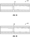
- the plasma jet will cut through the lower housing 62 and then cut the surrounding tubular 80 as shown in FIG. 7B .
- the uniformity of detonation of the booster explosive pellet 57, followed by the uniform detonation of the explosives 65 and 68, combine to cause the near simultaneous compression of both liners 66 and 67.
- the near simultaneous compression of both liners 66 and 67 result in a straight cut in the tubular 82 as shown in FIG. 7B compared with the prior art which causes a curved cut 81 as shown in FIG. 7A .
- the bridge wire segments 51 burst, as shown in FIG. 5 , they will produce shock waves 59 that will travel substantially perpendicular to the PCB 52.
- the shock waves 59 will travel at the same speed such that with each time interval, t1, t2, and t3, the shock waves stay roughly the same perpendicular distance from their originating bridge wire segment 51.
- FIG. 6 Another example of the discontinuous bridge wire design is shown in FIG. 6 .
- the PCB 52 is located within the booster explosive pellet 57.
- the bridge wire segments 51 are mounted onto the PCB 52 using contact pads 77. When a detonation signal is sent from a fireset the individual bridge wire segments 51 each explode or burst, causing explosive pellet 57 to detonate at a plurality of locations simultaneously.
- the design allows for the plurality of detonation points to ensure that the explosive waves are no longer biased to one end of the booster or the other.
Landscapes
- Engineering & Computer Science (AREA)
- Geology (AREA)
- Life Sciences & Earth Sciences (AREA)
- Mining & Mineral Resources (AREA)
- General Engineering & Computer Science (AREA)
- Physics & Mathematics (AREA)
- Environmental & Geological Engineering (AREA)
- Fluid Mechanics (AREA)
- General Life Sciences & Earth Sciences (AREA)
- Geochemistry & Mineralogy (AREA)
- Chemical & Material Sciences (AREA)
- Chemical Kinetics & Catalysis (AREA)
- General Chemical & Material Sciences (AREA)
- Perforating, Stamping-Out Or Severing By Means Other Than Cutting (AREA)
Priority Applications (1)
| Application Number | Priority Date | Filing Date | Title |
|---|---|---|---|
| PL15818654T PL3167147T3 (pl) | 2014-07-10 | 2015-07-10 | Urządzenie do kształtowania fali detonacyjnej wybuchowego mostka oporowego |
Applications Claiming Priority (2)
| Application Number | Priority Date | Filing Date | Title |
|---|---|---|---|
| US201462022751P | 2014-07-10 | 2014-07-10 | |
| PCT/US2015/039897 WO2016007829A1 (en) | 2014-07-10 | 2015-07-10 | Exploding bridge wire detonation wave shaper |
Publications (3)
| Publication Number | Publication Date |
|---|---|
| EP3167147A1 EP3167147A1 (en) | 2017-05-17 |
| EP3167147A4 EP3167147A4 (en) | 2018-02-28 |
| EP3167147B1 true EP3167147B1 (en) | 2020-01-29 |
Family
ID=55064945
Family Applications (1)
| Application Number | Title | Priority Date | Filing Date |
|---|---|---|---|
| EP15818654.4A Active EP3167147B1 (en) | 2014-07-10 | 2015-07-10 | Exploding bridge wire detonation wave shaper |
Country Status (5)
| Country | Link |
|---|---|
| US (2) | US10519736B2 (pl) |
| EP (1) | EP3167147B1 (pl) |
| CA (1) | CA2948664C (pl) |
| PL (1) | PL3167147T3 (pl) |
| WO (1) | WO2016007829A1 (pl) |
Cited By (2)
| Publication number | Priority date | Publication date | Assignee | Title |
|---|---|---|---|---|
| US12535304B2 (en) | 2024-06-13 | 2026-01-27 | Raytheon Company | Multiple shaped charge jet (SCJ) warhead |
| US12566052B2 (en) | 2024-06-13 | 2026-03-03 | Raytheon Company | Multiple Explosively Formed Penetrator (EFP) warhead |
Families Citing this family (14)
| Publication number | Priority date | Publication date | Assignee | Title |
|---|---|---|---|---|
| US10519736B2 (en) | 2014-07-10 | 2019-12-31 | Hunting Titan, Inc. | Exploding bridge wire detonation wave shaper |
| WO2019148009A2 (en) * | 2018-01-25 | 2019-08-01 | Hunting Titan, Inc. | Cluster gun system |
| US11994008B2 (en) | 2018-08-10 | 2024-05-28 | Gr Energy Services Management, Lp | Loaded perforating gun with plunging charge assembly and method of using same |
| US11078763B2 (en) | 2018-08-10 | 2021-08-03 | Gr Energy Services Management, Lp | Downhole perforating tool with integrated detonation assembly and method of using same |
| US10858919B2 (en) | 2018-08-10 | 2020-12-08 | Gr Energy Services Management, Lp | Quick-locking detonation assembly of a downhole perforating tool and method of using same |
| US11536104B2 (en) | 2018-08-16 | 2022-12-27 | James G. Rairigh | Methods of pre-testing expansion charge for selectively expanding a wall of a tubular, and methods of selectively expanding walls of nested tubulars |
| EP3837064B1 (en) | 2018-08-16 | 2025-12-17 | Rairigh, James, G. | Shaped charge assembly, explosive units, and methods for selectively expanding wall of a tubular |
| US11781393B2 (en) | 2018-08-16 | 2023-10-10 | James G. Rairigh | Explosive downhole tools having improved wellbore conveyance and debris properties, methods of using the explosive downhole tools in a wellbore, and explosive units for explosive column tools |
| US12392211B2 (en) | 2018-08-16 | 2025-08-19 | W.T. Bell International, Inc. | Explosive downhole tools having improved wellbore conveyance and debris properties, methods of using the explosive downhole tools in a wellbore, and explosive units for explosive column tools |
| US11480021B2 (en) | 2018-08-16 | 2022-10-25 | James G. Rairigh | Shaped charge assembly, explosive units, and methods for selectively expanding wall of a tubular |
| CA3109407C (en) | 2018-08-16 | 2022-01-18 | James G. Rairigh | Duel end firing explosive column tools and methods for selectively expanding a wall of a tubular |
| EP4251850A4 (en) * | 2020-12-18 | 2024-10-16 | Rairigh, James, G. | Shaped charge assembly, explosive units, and methods for selectively expanding wall of a tubular |
| CN113819817B (zh) * | 2021-10-20 | 2024-07-12 | 中国工程物理研究院总体工程研究所 | 一种弹载电路的物理自毁装置 |
| US12173994B2 (en) | 2023-04-28 | 2024-12-24 | L3Harris Technologies, Inc. | Shaped charge systems with waveshaper-embedded fuzing |
Citations (2)
| Publication number | Priority date | Publication date | Assignee | Title |
|---|---|---|---|---|
| US20050178282A1 (en) * | 2001-11-27 | 2005-08-18 | Schlumberger Technology Corporation | Integrated detonators for use with explosive devices |
| US20120067578A1 (en) * | 2010-09-22 | 2012-03-22 | Owen Oil Tools Lp | Wellbore tubular cutter |
Family Cites Families (16)
| Publication number | Priority date | Publication date | Assignee | Title |
|---|---|---|---|---|
| US2086527A (en) * | 1935-10-30 | 1937-07-13 | Du Pont | Electric blasting initiator |
| US2839997A (en) * | 1950-05-12 | 1958-06-24 | Joseph H Church | Shaped charges |
| US3208379A (en) | 1961-02-21 | 1965-09-28 | Special Devices Inc | Squib arrangement initiated by exploding wire |
| US3457859A (en) * | 1967-11-24 | 1969-07-29 | Hercules Inc | Method and system for initiating explosive composition |
| US3742856A (en) * | 1969-06-30 | 1973-07-03 | Us Navy | Advanced continuous warhead |
| US4788913A (en) * | 1971-06-02 | 1988-12-06 | The United States Of America As Represented By The United States Department Of Energy | Flying-plate detonator using a high-density high explosive |
| US4018293A (en) * | 1976-01-12 | 1977-04-19 | The Keller Corporation | Method and apparatus for controlled fracturing of subterranean formations |
| US5505134A (en) * | 1993-09-01 | 1996-04-09 | Schlumberger Technical Corporation | Perforating gun having a plurality of charges including a corresponding plurality of exploding foil or exploding bridgewire initiator apparatus responsive to a pulse of current for simultaneously detonating the plurality of charges |
| US5859383A (en) | 1996-09-18 | 1999-01-12 | Davison; David K. | Electrically activated, metal-fueled explosive device |
| US8770301B2 (en) * | 2001-09-10 | 2014-07-08 | William T. Bell | Explosive well tool firing head |
| US6761116B2 (en) * | 2001-10-17 | 2004-07-13 | Textron Sytems Corporation | Constant output high-precision microcapillary pyrotechnic initiator |
| US7104326B2 (en) * | 2003-12-15 | 2006-09-12 | Halliburton Energy Services, Inc. | Apparatus and method for severing pipe utilizing a multi-point initiation explosive device |
| US7661367B2 (en) * | 2004-10-08 | 2010-02-16 | Schlumberger Technology Corporation | Radial-linear shaped charge pipe cutter |
| US20090266259A1 (en) * | 2008-04-24 | 2009-10-29 | Rustick Joseph M | Flat electric match |
| US20120234193A1 (en) * | 2011-03-17 | 2012-09-20 | Special Devices, Inc. | Igniter with a locked consolidated powder charge |
| US10519736B2 (en) | 2014-07-10 | 2019-12-31 | Hunting Titan, Inc. | Exploding bridge wire detonation wave shaper |
-
2015
- 2015-07-10 US US15/325,303 patent/US10519736B2/en active Active
- 2015-07-10 CA CA2948664A patent/CA2948664C/en not_active Expired - Fee Related
- 2015-07-10 PL PL15818654T patent/PL3167147T3/pl unknown
- 2015-07-10 EP EP15818654.4A patent/EP3167147B1/en active Active
- 2015-07-10 WO PCT/US2015/039897 patent/WO2016007829A1/en not_active Ceased
-
2019
- 2019-11-26 US US16/696,669 patent/US20200095841A1/en not_active Abandoned
Patent Citations (3)
| Publication number | Priority date | Publication date | Assignee | Title |
|---|---|---|---|---|
| US20050178282A1 (en) * | 2001-11-27 | 2005-08-18 | Schlumberger Technology Corporation | Integrated detonators for use with explosive devices |
| US20120067578A1 (en) * | 2010-09-22 | 2012-03-22 | Owen Oil Tools Lp | Wellbore tubular cutter |
| US8561683B2 (en) * | 2010-09-22 | 2013-10-22 | Owen Oil Tools, Lp | Wellbore tubular cutter |
Cited By (2)
| Publication number | Priority date | Publication date | Assignee | Title |
|---|---|---|---|---|
| US12535304B2 (en) | 2024-06-13 | 2026-01-27 | Raytheon Company | Multiple shaped charge jet (SCJ) warhead |
| US12566052B2 (en) | 2024-06-13 | 2026-03-03 | Raytheon Company | Multiple Explosively Formed Penetrator (EFP) warhead |
Also Published As
| Publication number | Publication date |
|---|---|
| US10519736B2 (en) | 2019-12-31 |
| US20200095841A1 (en) | 2020-03-26 |
| CA2948664A1 (en) | 2016-01-14 |
| PL3167147T3 (pl) | 2020-07-13 |
| US20170191328A1 (en) | 2017-07-06 |
| WO2016007829A1 (en) | 2016-01-14 |
| CA2948664C (en) | 2020-06-30 |
| EP3167147A1 (en) | 2017-05-17 |
| EP3167147A4 (en) | 2018-02-28 |
Similar Documents
| Publication | Publication Date | Title |
|---|---|---|
| EP3167147B1 (en) | Exploding bridge wire detonation wave shaper | |
| US12091949B2 (en) | Universal plug and play perforating gun tandem | |
| EP1409839B1 (en) | Method and apparatus for detonating an explosive charge | |
| US6557636B2 (en) | Method and apparatus for perforating a well | |
| US20030000411A1 (en) | Method and apparatus for detonating an explosive charge | |
| US20030001753A1 (en) | Method and apparatus for wireless transmission down a well | |
| RU2557281C2 (ru) | Кумулятивный заряд | |
| US8919236B2 (en) | Perforating gun drop sub | |
| US20170121236A1 (en) | Fiber optic cable in det cord | |
| US11629585B2 (en) | Integrated coaxial perforating acidizing operation | |
| US20150247370A1 (en) | Explosive sever seal mechanism | |
| US20240280350A1 (en) | Stamped and Layered Case Materials for Shaped Charges | |
| US20170145767A1 (en) | Well-component severing tool with a radially-nonuniform explosive cartridge | |
| WO2007031001A1 (fr) | Dispositif de perforation composé exempt de corps | |
| US2986089A (en) | Debris-free perforating gun | |
| US10316629B2 (en) | Pressure-restrictor plate for a partially loaded perforating gun | |
| CA3126028C (en) | Integrated coaxial perforating acidizing operation |
Legal Events
| Date | Code | Title | Description |
|---|---|---|---|
| STAA | Information on the status of an ep patent application or granted ep patent |
Free format text: STATUS: THE INTERNATIONAL PUBLICATION HAS BEEN MADE |
|
| PUAI | Public reference made under article 153(3) epc to a published international application that has entered the european phase |
Free format text: ORIGINAL CODE: 0009012 |
|
| STAA | Information on the status of an ep patent application or granted ep patent |
Free format text: STATUS: REQUEST FOR EXAMINATION WAS MADE |
|
| 17P | Request for examination filed |
Effective date: 20170210 |
|
| AK | Designated contracting states |
Kind code of ref document: A1 Designated state(s): AL AT BE BG CH CY CZ DE DK EE ES FI FR GB GR HR HU IE IS IT LI LT LU LV MC MK MT NL NO PL PT RO RS SE SI SK SM TR |
|
| AX | Request for extension of the european patent |
Extension state: BA ME |
|
| RAP1 | Party data changed (applicant data changed or rights of an application transferred) |
Owner name: HUNTING TITAN INC. |
|
| DAV | Request for validation of the european patent (deleted) | ||
| DAX | Request for extension of the european patent (deleted) | ||
| RAP1 | Party data changed (applicant data changed or rights of an application transferred) |
Owner name: HUNTING TITAN, INC. |
|
| A4 | Supplementary search report drawn up and despatched |
Effective date: 20180130 |
|
| RIC1 | Information provided on ipc code assigned before grant |
Ipc: F42B 3/12 20060101ALI20180124BHEP Ipc: E21B 29/02 20060101AFI20180124BHEP Ipc: E21B 43/1185 20060101ALI20180124BHEP |
|
| RIC1 | Information provided on ipc code assigned before grant |
Ipc: E21B 29/02 20060101AFI20180516BHEP Ipc: E21B 43/1185 20060101ALI20180516BHEP Ipc: F42B 3/12 20060101ALI20180516BHEP |
|
| STAA | Information on the status of an ep patent application or granted ep patent |
Free format text: STATUS: EXAMINATION IS IN PROGRESS |
|
| 17Q | First examination report despatched |
Effective date: 20190305 |
|
| GRAP | Despatch of communication of intention to grant a patent |
Free format text: ORIGINAL CODE: EPIDOSNIGR1 |
|
| STAA | Information on the status of an ep patent application or granted ep patent |
Free format text: STATUS: GRANT OF PATENT IS INTENDED |
|
| INTG | Intention to grant announced |
Effective date: 20191011 |
|
| GRAS | Grant fee paid |
Free format text: ORIGINAL CODE: EPIDOSNIGR3 |
|
| GRAA | (expected) grant |
Free format text: ORIGINAL CODE: 0009210 |
|
| STAA | Information on the status of an ep patent application or granted ep patent |
Free format text: STATUS: THE PATENT HAS BEEN GRANTED |
|
| AK | Designated contracting states |
Kind code of ref document: B1 Designated state(s): AL AT BE BG CH CY CZ DE DK EE ES FI FR GB GR HR HU IE IS IT LI LT LU LV MC MK MT NL NO PL PT RO RS SE SI SK SM TR |
|
| REG | Reference to a national code |
Ref country code: GB Ref legal event code: FG4D |
|
| REG | Reference to a national code |
Ref country code: CH Ref legal event code: EP |
|
| REG | Reference to a national code |
Ref country code: AT Ref legal event code: REF Ref document number: 1228626 Country of ref document: AT Kind code of ref document: T Effective date: 20200215 |
|
| REG | Reference to a national code |
Ref country code: IE Ref legal event code: FG4D |
|
| REG | Reference to a national code |
Ref country code: DE Ref legal event code: R096 Ref document number: 602015046168 Country of ref document: DE |
|
| REG | Reference to a national code |
Ref country code: NL Ref legal event code: FP |
|
| REG | Reference to a national code |
Ref country code: SE Ref legal event code: TRGR |
|
| REG | Reference to a national code |
Ref country code: NO Ref legal event code: T2 Effective date: 20200129 |
|
| PG25 | Lapsed in a contracting state [announced via postgrant information from national office to epo] |
Ref country code: RS Free format text: LAPSE BECAUSE OF FAILURE TO SUBMIT A TRANSLATION OF THE DESCRIPTION OR TO PAY THE FEE WITHIN THE PRESCRIBED TIME-LIMIT Effective date: 20200129 Ref country code: FI Free format text: LAPSE BECAUSE OF FAILURE TO SUBMIT A TRANSLATION OF THE DESCRIPTION OR TO PAY THE FEE WITHIN THE PRESCRIBED TIME-LIMIT Effective date: 20200129 Ref country code: PT Free format text: LAPSE BECAUSE OF FAILURE TO SUBMIT A TRANSLATION OF THE DESCRIPTION OR TO PAY THE FEE WITHIN THE PRESCRIBED TIME-LIMIT Effective date: 20200621 |
|
| REG | Reference to a national code |
Ref country code: LT Ref legal event code: MG4D |
|
| PG25 | Lapsed in a contracting state [announced via postgrant information from national office to epo] |
Ref country code: HR Free format text: LAPSE BECAUSE OF FAILURE TO SUBMIT A TRANSLATION OF THE DESCRIPTION OR TO PAY THE FEE WITHIN THE PRESCRIBED TIME-LIMIT Effective date: 20200129 Ref country code: LV Free format text: LAPSE BECAUSE OF FAILURE TO SUBMIT A TRANSLATION OF THE DESCRIPTION OR TO PAY THE FEE WITHIN THE PRESCRIBED TIME-LIMIT Effective date: 20200129 Ref country code: BG Free format text: LAPSE BECAUSE OF FAILURE TO SUBMIT A TRANSLATION OF THE DESCRIPTION OR TO PAY THE FEE WITHIN THE PRESCRIBED TIME-LIMIT Effective date: 20200429 Ref country code: IS Free format text: LAPSE BECAUSE OF FAILURE TO SUBMIT A TRANSLATION OF THE DESCRIPTION OR TO PAY THE FEE WITHIN THE PRESCRIBED TIME-LIMIT Effective date: 20200529 Ref country code: GR Free format text: LAPSE BECAUSE OF FAILURE TO SUBMIT A TRANSLATION OF THE DESCRIPTION OR TO PAY THE FEE WITHIN THE PRESCRIBED TIME-LIMIT Effective date: 20200430 |
|
| PGFP | Annual fee paid to national office [announced via postgrant information from national office to epo] |
Ref country code: GB Payment date: 20200622 Year of fee payment: 6 |
|
| PG25 | Lapsed in a contracting state [announced via postgrant information from national office to epo] |
Ref country code: CZ Free format text: LAPSE BECAUSE OF FAILURE TO SUBMIT A TRANSLATION OF THE DESCRIPTION OR TO PAY THE FEE WITHIN THE PRESCRIBED TIME-LIMIT Effective date: 20200129 Ref country code: RO Free format text: LAPSE BECAUSE OF FAILURE TO SUBMIT A TRANSLATION OF THE DESCRIPTION OR TO PAY THE FEE WITHIN THE PRESCRIBED TIME-LIMIT Effective date: 20200129 Ref country code: ES Free format text: LAPSE BECAUSE OF FAILURE TO SUBMIT A TRANSLATION OF THE DESCRIPTION OR TO PAY THE FEE WITHIN THE PRESCRIBED TIME-LIMIT Effective date: 20200129 Ref country code: SK Free format text: LAPSE BECAUSE OF FAILURE TO SUBMIT A TRANSLATION OF THE DESCRIPTION OR TO PAY THE FEE WITHIN THE PRESCRIBED TIME-LIMIT Effective date: 20200129 Ref country code: DK Free format text: LAPSE BECAUSE OF FAILURE TO SUBMIT A TRANSLATION OF THE DESCRIPTION OR TO PAY THE FEE WITHIN THE PRESCRIBED TIME-LIMIT Effective date: 20200129 Ref country code: LT Free format text: LAPSE BECAUSE OF FAILURE TO SUBMIT A TRANSLATION OF THE DESCRIPTION OR TO PAY THE FEE WITHIN THE PRESCRIBED TIME-LIMIT Effective date: 20200129 Ref country code: SM Free format text: LAPSE BECAUSE OF FAILURE TO SUBMIT A TRANSLATION OF THE DESCRIPTION OR TO PAY THE FEE WITHIN THE PRESCRIBED TIME-LIMIT Effective date: 20200129 Ref country code: EE Free format text: LAPSE BECAUSE OF FAILURE TO SUBMIT A TRANSLATION OF THE DESCRIPTION OR TO PAY THE FEE WITHIN THE PRESCRIBED TIME-LIMIT Effective date: 20200129 |
|
| PGFP | Annual fee paid to national office [announced via postgrant information from national office to epo] |
Ref country code: NO Payment date: 20200702 Year of fee payment: 6 |
|
| REG | Reference to a national code |
Ref country code: DE Ref legal event code: R097 Ref document number: 602015046168 Country of ref document: DE |
|
| REG | Reference to a national code |
Ref country code: AT Ref legal event code: MK05 Ref document number: 1228626 Country of ref document: AT Kind code of ref document: T Effective date: 20200129 |
|
| PLBE | No opposition filed within time limit |
Free format text: ORIGINAL CODE: 0009261 |
|
| STAA | Information on the status of an ep patent application or granted ep patent |
Free format text: STATUS: NO OPPOSITION FILED WITHIN TIME LIMIT |
|
| 26N | No opposition filed |
Effective date: 20201030 |
|
| PG25 | Lapsed in a contracting state [announced via postgrant information from national office to epo] |
Ref country code: AT Free format text: LAPSE BECAUSE OF FAILURE TO SUBMIT A TRANSLATION OF THE DESCRIPTION OR TO PAY THE FEE WITHIN THE PRESCRIBED TIME-LIMIT Effective date: 20200129 Ref country code: IT Free format text: LAPSE BECAUSE OF FAILURE TO SUBMIT A TRANSLATION OF THE DESCRIPTION OR TO PAY THE FEE WITHIN THE PRESCRIBED TIME-LIMIT Effective date: 20200129 |
|
| PG25 | Lapsed in a contracting state [announced via postgrant information from national office to epo] |
Ref country code: SI Free format text: LAPSE BECAUSE OF FAILURE TO SUBMIT A TRANSLATION OF THE DESCRIPTION OR TO PAY THE FEE WITHIN THE PRESCRIBED TIME-LIMIT Effective date: 20200129 Ref country code: MC Free format text: LAPSE BECAUSE OF FAILURE TO SUBMIT A TRANSLATION OF THE DESCRIPTION OR TO PAY THE FEE WITHIN THE PRESCRIBED TIME-LIMIT Effective date: 20200129 |
|
| REG | Reference to a national code |
Ref country code: CH Ref legal event code: PL |
|
| REG | Reference to a national code |
Ref country code: SE Ref legal event code: EUG |
|
| REG | Reference to a national code |
Ref country code: NL Ref legal event code: MM Effective date: 20200801 |
|
| REG | Reference to a national code |
Ref country code: BE Ref legal event code: MM Effective date: 20200731 |
|
| PG25 | Lapsed in a contracting state [announced via postgrant information from national office to epo] |
Ref country code: CH Free format text: LAPSE BECAUSE OF NON-PAYMENT OF DUE FEES Effective date: 20200731 Ref country code: NL Free format text: LAPSE BECAUSE OF NON-PAYMENT OF DUE FEES Effective date: 20200801 Ref country code: LU Free format text: LAPSE BECAUSE OF NON-PAYMENT OF DUE FEES Effective date: 20200710 Ref country code: LI Free format text: LAPSE BECAUSE OF NON-PAYMENT OF DUE FEES Effective date: 20200731 |
|
| PG25 | Lapsed in a contracting state [announced via postgrant information from national office to epo] |
Ref country code: BE Free format text: LAPSE BECAUSE OF NON-PAYMENT OF DUE FEES Effective date: 20200731 Ref country code: SE Free format text: LAPSE BECAUSE OF NON-PAYMENT OF DUE FEES Effective date: 20200711 |
|
| PG25 | Lapsed in a contracting state [announced via postgrant information from national office to epo] |
Ref country code: IE Free format text: LAPSE BECAUSE OF NON-PAYMENT OF DUE FEES Effective date: 20200710 |
|
| PGFP | Annual fee paid to national office [announced via postgrant information from national office to epo] |
Ref country code: FR Payment date: 20210729 Year of fee payment: 7 |
|
| PGFP | Annual fee paid to national office [announced via postgrant information from national office to epo] |
Ref country code: DE Payment date: 20210505 Year of fee payment: 7 |
|
| REG | Reference to a national code |
Ref country code: NO Ref legal event code: MMEP |
|
| GBPC | Gb: european patent ceased through non-payment of renewal fee |
Effective date: 20210710 |
|
| PG25 | Lapsed in a contracting state [announced via postgrant information from national office to epo] |
Ref country code: GB Free format text: LAPSE BECAUSE OF NON-PAYMENT OF DUE FEES Effective date: 20210710 |
|
| PG25 | Lapsed in a contracting state [announced via postgrant information from national office to epo] |
Ref country code: TR Free format text: LAPSE BECAUSE OF FAILURE TO SUBMIT A TRANSLATION OF THE DESCRIPTION OR TO PAY THE FEE WITHIN THE PRESCRIBED TIME-LIMIT Effective date: 20200129 Ref country code: NO Free format text: LAPSE BECAUSE OF NON-PAYMENT OF DUE FEES Effective date: 20210731 Ref country code: MT Free format text: LAPSE BECAUSE OF FAILURE TO SUBMIT A TRANSLATION OF THE DESCRIPTION OR TO PAY THE FEE WITHIN THE PRESCRIBED TIME-LIMIT Effective date: 20200129 Ref country code: CY Free format text: LAPSE BECAUSE OF FAILURE TO SUBMIT A TRANSLATION OF THE DESCRIPTION OR TO PAY THE FEE WITHIN THE PRESCRIBED TIME-LIMIT Effective date: 20200129 |
|
| PG25 | Lapsed in a contracting state [announced via postgrant information from national office to epo] |
Ref country code: MK Free format text: LAPSE BECAUSE OF FAILURE TO SUBMIT A TRANSLATION OF THE DESCRIPTION OR TO PAY THE FEE WITHIN THE PRESCRIBED TIME-LIMIT Effective date: 20200129 Ref country code: AL Free format text: LAPSE BECAUSE OF FAILURE TO SUBMIT A TRANSLATION OF THE DESCRIPTION OR TO PAY THE FEE WITHIN THE PRESCRIBED TIME-LIMIT Effective date: 20200129 |
|
| PG25 | Lapsed in a contracting state [announced via postgrant information from national office to epo] |
Ref country code: PL Free format text: LAPSE BECAUSE OF NON-PAYMENT OF DUE FEES Effective date: 20200710 |
|
| REG | Reference to a national code |
Ref country code: DE Ref legal event code: R119 Ref document number: 602015046168 Country of ref document: DE |
|
| PG25 | Lapsed in a contracting state [announced via postgrant information from national office to epo] |
Ref country code: FR Free format text: LAPSE BECAUSE OF NON-PAYMENT OF DUE FEES Effective date: 20220731 |
|
| PG25 | Lapsed in a contracting state [announced via postgrant information from national office to epo] |
Ref country code: DE Free format text: LAPSE BECAUSE OF NON-PAYMENT OF DUE FEES Effective date: 20230201 |