EP3166875B1 - Lift configuration for carriage-based warehouse - Google Patents
Lift configuration for carriage-based warehouse Download PDFInfo
- Publication number
- EP3166875B1 EP3166875B1 EP15819495.1A EP15819495A EP3166875B1 EP 3166875 B1 EP3166875 B1 EP 3166875B1 EP 15819495 A EP15819495 A EP 15819495A EP 3166875 B1 EP3166875 B1 EP 3166875B1
- Authority
- EP
- European Patent Office
- Prior art keywords
- lift
- racks
- articles
- aisle
- lift assemblies
- Prior art date
- Legal status (The legal status is an assumption and is not a legal conclusion. Google has not performed a legal analysis and makes no representation as to the accuracy of the status listed.)
- Active
Links
Images


Classifications
-
- B—PERFORMING OPERATIONS; TRANSPORTING
- B65—CONVEYING; PACKING; STORING; HANDLING THIN OR FILAMENTARY MATERIAL
- B65G—TRANSPORT OR STORAGE DEVICES, e.g. CONVEYORS FOR LOADING OR TIPPING, SHOP CONVEYOR SYSTEMS OR PNEUMATIC TUBE CONVEYORS
- B65G1/00—Storing articles, individually or in orderly arrangement, in warehouses or magazines
- B65G1/02—Storage devices
- B65G1/04—Storage devices mechanical
- B65G1/137—Storage devices mechanical with arrangements or automatic control means for selecting which articles are to be removed
-
- B—PERFORMING OPERATIONS; TRANSPORTING
- B65—CONVEYING; PACKING; STORING; HANDLING THIN OR FILAMENTARY MATERIAL
- B65G—TRANSPORT OR STORAGE DEVICES, e.g. CONVEYORS FOR LOADING OR TIPPING, SHOP CONVEYOR SYSTEMS OR PNEUMATIC TUBE CONVEYORS
- B65G1/00—Storing articles, individually or in orderly arrangement, in warehouses or magazines
- B65G1/02—Storage devices
- B65G1/04—Storage devices mechanical
- B65G1/06—Storage devices mechanical with means for presenting articles for removal at predetermined position or level
- B65G1/065—Storage devices mechanical with means for presenting articles for removal at predetermined position or level with self propelled cars
-
- B—PERFORMING OPERATIONS; TRANSPORTING
- B65—CONVEYING; PACKING; STORING; HANDLING THIN OR FILAMENTARY MATERIAL
- B65G—TRANSPORT OR STORAGE DEVICES, e.g. CONVEYORS FOR LOADING OR TIPPING, SHOP CONVEYOR SYSTEMS OR PNEUMATIC TUBE CONVEYORS
- B65G1/00—Storing articles, individually or in orderly arrangement, in warehouses or magazines
- B65G1/02—Storage devices
- B65G1/04—Storage devices mechanical
- B65G1/0492—Storage devices mechanical with cars adapted to travel in storage aisles
Definitions
- the present invention is directed to an automated warehouse system having at least two stacked longitudinally extending racks that are laterally separated by an aisle and automated carriages at some or all of the levels to store articles to and retrieve articles from each of the racks at that level, and a method of storing articles to and retrieving articles from such automated warehouse system.
- the articles are supplied to each level of the warehouse system with a lift arrangement.
- the carriages retrieve articles from storage positions in the racks and dispatch the articles to the lift arrangement or retrieve articles from the lift arrangement and store the articles to a storage position on one of the racks.
- a computer system coordinates the lift arrangement and the carriages in order to be able to retrieve any articles stored to the automated warehouse system when that article is needed, for example, to fulfil an order in an e-commerce or mail-order system.
- the article may be a container, such as a tote, that contains a plurality of individual items of the same type, or stock-keeping unit (SKU), or a mixture of different types of items, or SKUs.
- the article may be a self-contained item that is packed by itself.
- the number of articles that can be stored to and retrieved from the automated warehouse system in a given period of time is a measure of the efficiency, or through-put, of the system.
- the WO 2013/090970 A2 discloses a rack storage system comprising storage racks, a load manipulation unit which has at least a first load lifting device with a transport device and a first buffer device with supplying devices, a rack aisle and guide tracks extending on the rack levels in the longitudinal direction of the rack aisle, single-level rack serving devices for transporting load, and a conveying system for transporting load to and from the load lifting device, said conveying system being connected to the load lifting device.
- EP 0 733 563 A1 discloses a merchandise handling equipment, which is able to handle merchandise without moving the merchandise to a bucket or the like and is also able to enhance the storage efficiency of the merchandise.
- the merchandise handling equipment is made up of a carriage including a pallet for placing merchandise thereon and runnable along a shelf plate, a pair of left and right extendable and contractible fork members respectively disposed in either side end portion of the pallet, a fork width adjusting mechanism for adjusting a mutually spaced distance between the pair of left and right fork members, and a fork extending and contracting mechanism for expanding and contracting the pair of left and right fork members substantially horizontally from the carriage to the shelf plate or vice versa, in which the pair of left and right fork members are operated to hold the merchandise between them and then the pair of left and right fork members are extended and contracted to thereby move the merchandise from one of the pallet and shelf plate to the other.
- DE 20 2014 100476 U1 discloses a storage rack arrangement with racks arranged parallel to one another in a storage area and with a supply conveyor system in a preliminary zone adjacent to the storage area, having the shelves having a plurality of storage locations arranged vertically one above the other and horizontally one beside the other for storing stored goods, the shelves extending substantially in a longitudinal direction and each having a plurality of shelf levels vertically one above the other, and some of the shelves being arranged spaced apart from one another in a transverse direction so as to each define a shelf aisle between them; the supply conveyor for supplying and removing stored goods to and from the racks; at least one stacker crane which can be moved horizontally in the rack aisles longitudinally along one of the rack levels or along a group of rack levels and which has a load-carrying means in each case for feeding the stored goods to and from the racks; a plurality of stationarily arranged vertical conveyors, each having a load receiving means, each of the load receiving means of the vertical conveyors being arranged to exchange the
- the present invention is directed toward improving the efficiency or through-put of an automated warehouse system. Improvements to the carriage design have increased the efficiency of the carriage so that the carriage is able to store and retrieve articles at a significantly faster rate than the known lift arrangements and are able to deliver articles to the carriage and retrieve articles from the carriage.
- An automated warehouse system and method of storing articles to and retrieving articles from an automated warehouse system are claimed respectively in claim 1 and in claim 9, and includes in particular at least two stacked longitudinally extending racks that are laterally separated by an aisle, each of said racks having a plurality of levels, with storage locations on each of the levels.
- An automated carriage at each of said levels travels longitudinally along the associated aisle and is adapted to store articles to and retrieve articles from each of the racks at that level.
- a lift arrangement for delivering articles to and retrieving articles from the levels of the stacked racks includes more than one lift assembly for at least one of the racks.
- the lift arrangement includes at least two lift assemblies for at least one of the racks.
- the lift arrangement may include at least two lift assemblies for each of the racks.
- the carriage is capable of storing articles to and retrieving articles from at least two separate rows of articles in at least one of the racks, each of the rows at a different distance from said aisle.
- At least two lift assemblies are laterally aligned with the at least two rows.
- a pass-through support may be provided for temporarily supporting articles being dispatched to or retrieved from the laterally spaced lift assembly. The pass-through support is aligned with the one of said rows that is farthest from said aisle.
- Access conveyors may be provided that supply articles to or receive articles from each of the lift assemblies.
- the access conveyors for the lift assemblies may be adapted to be positioned at different elevations.
- a picking station may be provided at each of the different elevations.
- the picking stations are connected with the access conveyors for the lift assemblies for the stacked racks. More than one access conveyor may be supplied for at least one of the lift assemblies.
- An article feeding conveyor may be connected with one of the access conveyors.
- the lift assemblies for at least one of the racks are positioned at different distances from the racks.
- One of said lift assemblies that is aligned with the row of articles that is farthest from said aisle may be closer to the racks than is the one of the lift assemblies that is aligned with the row of articles that is closest to the aisle.
- an automated warehouse system 10 has at least two stacked longitudinally extending racks 12 that are laterally separated by an aisle 16. Each rack 12 has a plurality of levels 14 with storage locations 15 on each of the levels.
- Such automated warehouse is generally described in U.S. Patent Application Publication No. 2011/0008137 by Shin Yamashita .
- a plurality of automated carriages 18 are provided, one at each of levels 14. While the invention may also be applied to an automated warehouse in which a carriage is capable of handling more than one level 14 and rides on a lift arrangement between levels, the invention is illustrated for use with the number of carriages equal to at least the number of levels of the warehouse.
- Automated carriage 18 travels longitudinally along the associated aisle 16 for the level and stores articles to and retrieves articles from storage locations 15 of each of the racks 12 at that level 14.
- automated carriage 18 is capable of storing articles to and retrieving articles from at least two separate rows 30, 32 of articles in each of racks 12. Each of said rows is at a different distance from aisle 16 with the row closest to aisle 16 designated as 30 and the row farthest from the aisle designated as 32. Such arrangement of articles is known as "double-deep" storage.
- the details of carriage 18 are disclosed in U.S. Patent Application Publication No. 2011/0008138 by Shin Yamashita . It should be understood that only one cell of an automated warehouse system is shown, while numerous cells are duplicated in an overall warehouse system.
- a lift arrangement generally shown at 20 is provided for delivering articles to and retrieving articles from the levels 14 of said stacked racks.
- lift arrangement 20 is made up of a first lift assembly 22, a second lift assembly 24, a third lift assembly 26 and a fourth lift assembly 28. Since there are four (4) lift assemblies and two racks 12, it can be seen that lift arrangement 20 has more than one lift assembly (22-28) for each rack 12.
- Each lift assembly (22-28) has a vertical mast 34 that extends at least the height of each rack 12 and a lift platform 36 that raises and lowers along mast 34 using conventional techniques.
- Platform 36 is made up of a plurality of driven rollers 37 which are capable of being driven in opposite directions for loading articles to platform 36 and unloading articles from the platform.
- an aisle conveyor 38 serves as a buffer to hold an article while it is awaiting the lift assembly to pick up that article or after it has been discharged from the lift assembly while the article is awaiting pick-up by carriage 18 to be stored to a storage location 15.
- a pair of access conveyors 42a, 42b are provided at a ground floor level 44 to feed articles to and/or receive articles from lift platform 36 and a pair of access conveyors 42c, 42d are provided at a different floor level, such as a mezzanine level 46 to feed articles to and/or receive articles from lift platform 36.
- the access conveyors may be arranged at different levels. For example, it may be possible to have more than four access conveyors for four lift assemblies and they may be placed at more than two levels of the warehouse. Indeed, it is an advantage of the invention that the use of access conveyors is decoupled from the lift assemblies.
- carriage 18 is capable of storing articles to and retrieving articles from at least two separate rows 30, 32 of articles in each of racks 12, with each of the rows at a different distance from aisle 16.
- the lift platforms 36 of two lift assemblies 22, 26 are laterally aligned respectively with two rows 30, 32 of one rack 12.
- the lift platforms 36 of two lift assemblies 24, 28 are laterally aligned respectively with two rows 30, 32 of the other rack 12.
- Carriage 18 is capable of handling articles to/from conveyors 38 of lift assemblies 22, 24 when in the solid-line position shown in Figs. 2 and 3 using the same motion as if the articles were being stored to or retrieved from inner rows 30 on the racks.
- Carriage 18 is also capable of handling articles to/from aisle conveyors 38 of lift assemblies 26 and 28 when in the dashed-line position shown in Fig. 3 using the same motion as if the articles were being stored to or retrieved from outer rows 32 on the racks.
- a pass-through support 40 is provided between aisle 16 and the aisle conveyor 38 for each lift assembly 26, 28 so that carriage 18 can have a continuous surface to slide articles to and from lift assemblies 26, 28.
- lift assemblies 26, 28 are longitudinally closer to racks 12 than are lift assemblies 22, 24. This longitudinal spacing allows carriage 18 to access the aisle conveyors 38 of all four lift assemblies in a simple lateral motion.
- carriage 18 it is possible for carriage 18 to store articles to only one row or more than two rows for each rack, in which case it is referred to triple-deep storage, quadruple-deep storage, or the like.
- triple-deep and quadruple-deep storage can be optimized, with the lift assemblies arranged using the principle set forth above in a manner that will be apparent to the skilled artisan.
- Flow paths of articles using lift assemblies 22-28 can be configured; however, they are most convenient for the particular installation and can even be changeable depending on the load of the warehouse.
- the outer lift assemblies 26, 28 can be used to feed articles to and receive articles from a process, such as a pick station, on one elevation of the facility while the inner lift assemblies 22, 24 service another process on another elevation of the facility.
- the inner lift assemblies 22, 24 can be incoming and the outer lift assemblies 26, 28 can be outgoing.
- some of the inbound flow paths can be from conveyors feeding articles to be stored to the automated warehouse. Other arrangements are possible and can be changed as needed.
Landscapes
- Engineering & Computer Science (AREA)
- Mechanical Engineering (AREA)
- Warehouses Or Storage Devices (AREA)
Description
- The present invention is directed to an automated warehouse system having at least two stacked longitudinally extending racks that are laterally separated by an aisle and automated carriages at some or all of the levels to store articles to and retrieve articles from each of the racks at that level, and a method of storing articles to and retrieving articles from such automated warehouse system.
- In such an automated warehouse system, the articles are supplied to each level of the warehouse system with a lift arrangement. The carriages retrieve articles from storage positions in the racks and dispatch the articles to the lift arrangement or retrieve articles from the lift arrangement and store the articles to a storage position on one of the racks. A computer system coordinates the lift arrangement and the carriages in order to be able to retrieve any articles stored to the automated warehouse system when that article is needed, for example, to fulfil an order in an e-commerce or mail-order system. The article may be a container, such as a tote, that contains a plurality of individual items of the same type, or stock-keeping unit (SKU), or a mixture of different types of items, or SKUs. Alternatively, the article may be a self-contained item that is packed by itself. The number of articles that can be stored to and retrieved from the automated warehouse system in a given period of time is a measure of the efficiency, or through-put, of the system.
- The
WO 2013/090970 A2 discloses a rack storage system comprising storage racks, a load manipulation unit which has at least a first load lifting device with a transport device and a first buffer device with supplying devices, a rack aisle and guide tracks extending on the rack levels in the longitudinal direction of the rack aisle, single-level rack serving devices for transporting load, and a conveying system for transporting load to and from the load lifting device, said conveying system being connected to the load lifting device. -
EP 0 733 563 A1 discloses a merchandise handling equipment, which is able to handle merchandise without moving the merchandise to a bucket or the like and is also able to enhance the storage efficiency of the merchandise. The merchandise handling equipment is made up of a carriage including a pallet for placing merchandise thereon and runnable along a shelf plate, a pair of left and right extendable and contractible fork members respectively disposed in either side end portion of the pallet, a fork width adjusting mechanism for adjusting a mutually spaced distance between the pair of left and right fork members, and a fork extending and contracting mechanism for expanding and contracting the pair of left and right fork members substantially horizontally from the carriage to the shelf plate or vice versa, in which the pair of left and right fork members are operated to hold the merchandise between them and then the pair of left and right fork members are extended and contracted to thereby move the merchandise from one of the pallet and shelf plate to the other. -
DE 20 2014 100476 U1DE 20 2014 100476 U1 discloses an automated warehouse system according to the preamble of claim 1. - The present invention is directed toward improving the efficiency or through-put of an automated warehouse system. Improvements to the carriage design have increased the efficiency of the carriage so that the carriage is able to store and retrieve articles at a significantly faster rate than the known lift arrangements and are able to deliver articles to the carriage and retrieve articles from the carriage.
- An automated warehouse system and method of storing articles to and retrieving articles from an automated warehouse system, according to an aspect of the invention, are claimed respectively in claim 1 and in claim 9, and includes in particular at least two stacked longitudinally extending racks that are laterally separated by an aisle, each of said racks having a plurality of levels, with storage locations on each of the levels. An automated carriage at each of said levels travels longitudinally along the associated aisle and is adapted to store articles to and retrieve articles from each of the racks at that level. A lift arrangement for delivering articles to and retrieving articles from the levels of the stacked racks includes more than one lift assembly for at least one of the racks.
- The lift arrangement includes at least two lift assemblies for at least one of the racks. The lift arrangement may include at least two lift assemblies for each of the racks.
- The carriage is capable of storing articles to and retrieving articles from at least two separate rows of articles in at least one of the racks, each of the rows at a different distance from said aisle. At least two lift assemblies are laterally aligned with the at least two rows. A pass-through support may be provided for temporarily supporting articles being dispatched to or retrieved from the laterally spaced lift assembly. The pass-through support is aligned with the one of said rows that is farthest from said aisle.
- Access conveyors may be provided that supply articles to or receive articles from each of the lift assemblies. The access conveyors for the lift assemblies may be adapted to be positioned at different elevations. A picking station may be provided at each of the different elevations. The picking stations are connected with the access conveyors for the lift assemblies for the stacked racks. More than one access conveyor may be supplied for at least one of the lift assemblies. An article feeding conveyor may be connected with one of the access conveyors.
- The lift assemblies for at least one of the racks are positioned at different distances from the racks. One of said lift assemblies that is aligned with the row of articles that is farthest from said aisle may be closer to the racks than is the one of the lift assemblies that is aligned with the row of articles that is closest to the aisle.
- These and other objects, advantages and features of this invention will become apparent upon review of the following specification in conjunction with the drawings.
-
-
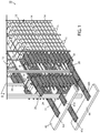
Fig. 1 is a perspective view of an automated warehouse system, according to an embodiment of the invention; -
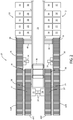
Fig. 2 is a sectional view taken along the lines II-II inFig. 1 ; -
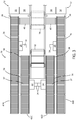
Fig. 3 is an enlarged view of a portion ofFig. 2 illustrating the lift arrangement; -
Fig. 4 is the same view asFig. 3 illustrating an example flow path through the lift arrangement; and -
Fig. 5 is the same view asFig. 3 illustrating another example of a flow path through the lift arrangement. - Referring now to the drawings and the illustrative embodiments depicted therein, an
automated warehouse system 10 has at least two stacked longitudinally extendingracks 12 that are laterally separated by anaisle 16. Eachrack 12 has a plurality oflevels 14 withstorage locations 15 on each of the levels. Such automated warehouse is generally described inU.S. Patent Application Publication No. 2011/0008137 by Shin Yamashita . A plurality ofautomated carriages 18 are provided, one at each oflevels 14. While the invention may also be applied to an automated warehouse in which a carriage is capable of handling more than onelevel 14 and rides on a lift arrangement between levels, the invention is illustrated for use with the number of carriages equal to at least the number of levels of the warehouse. Any combination of carriages and levels shall hereinafter be referred to as a carriage at each level.Automated carriage 18 travels longitudinally along the associatedaisle 16 for the level and stores articles to and retrieves articles fromstorage locations 15 of each of theracks 12 at thatlevel 14. In the illustrated embodiment,automated carriage 18 is capable of storing articles to and retrieving articles from at least twoseparate rows racks 12. Each of said rows is at a different distance fromaisle 16 with the row closest toaisle 16 designated as 30 and the row farthest from the aisle designated as 32. Such arrangement of articles is known as "double-deep" storage. The details ofcarriage 18 are disclosed inU.S. Patent Application Publication No. 2011/0008138 by Shin Yamashita . It should be understood that only one cell of an automated warehouse system is shown, while numerous cells are duplicated in an overall warehouse system. - A lift arrangement generally shown at 20 is provided for delivering articles to and retrieving articles from the
levels 14 of said stacked racks. As will be described in more detail below,lift arrangement 20 is made up of afirst lift assembly 22, asecond lift assembly 24, athird lift assembly 26 and afourth lift assembly 28. Since there are four (4) lift assemblies and tworacks 12, it can be seen thatlift arrangement 20 has more than one lift assembly (22-28) for eachrack 12. Each lift assembly (22-28) has avertical mast 34 that extends at least the height of eachrack 12 and alift platform 36 that raises and lowers alongmast 34 using conventional techniques.Platform 36 is made up of a plurality of drivenrollers 37 which are capable of being driven in opposite directions for loading articles toplatform 36 and unloading articles from the platform. At each level ofracks 12, anaisle conveyor 38 serves as a buffer to hold an article while it is awaiting the lift assembly to pick up that article or after it has been discharged from the lift assembly while the article is awaiting pick-up bycarriage 18 to be stored to astorage location 15. In the illustrated embodiment, a pair ofaccess conveyors ground floor level 44 to feed articles to and/or receive articles fromlift platform 36 and a pair ofaccess conveyors mezzanine level 46 to feed articles to and/or receive articles fromlift platform 36. It should be understood that other numbers of access conveyors are possible and do not need to equal to the number of lift assemblies. Also, the access conveyors may be arranged at different levels. For example, it may be possible to have more than four access conveyors for four lift assemblies and they may be placed at more than two levels of the warehouse. Indeed, it is an advantage of the invention that the use of access conveyors is decoupled from the lift assemblies. - As mentioned above,
carriage 18 is capable of storing articles to and retrieving articles from at least twoseparate rows racks 12, with each of the rows at a different distance fromaisle 16. Thelift platforms 36 of twolift assemblies rows rack 12. Thelift platforms 36 of twolift assemblies rows other rack 12.Carriage 18 is capable of handling articles to/fromconveyors 38 oflift assemblies Figs. 2 and3 using the same motion as if the articles were being stored to or retrieved frominner rows 30 on the racks.Carriage 18 is also capable of handling articles to/fromaisle conveyors 38 oflift assemblies Fig. 3 using the same motion as if the articles were being stored to or retrieved fromouter rows 32 on the racks. A pass-throughsupport 40 is provided betweenaisle 16 and theaisle conveyor 38 for eachlift assembly carriage 18 can have a continuous surface to slide articles to and fromlift assemblies lift assemblies racks 12 than arelift assemblies carriage 18 to access theaisle conveyors 38 of all four lift assemblies in a simple lateral motion. It should be understood that it is possible forcarriage 18 to store articles to only one row or more than two rows for each rack, in which case it is referred to triple-deep storage, quadruple-deep storage, or the like. By increasing the number of lift assemblies, such triple-deep and quadruple-deep storage can be optimized, with the lift assemblies arranged using the principle set forth above in a manner that will be apparent to the skilled artisan. - Flow paths of articles using lift assemblies 22-28 can be configured; however, they are most convenient for the particular installation and can even be changeable depending on the load of the warehouse. For example, as can be seen in
Fig. 4 , theouter lift assemblies inner lift assemblies Fig. 5 , theinner lift assemblies outer lift assemblies - While the foregoing description describes several embodiments of the present invention, it will be understood by those skilled in the art that variations and modifications to these embodiments may be made without departing from the scope of the invention, as defined in the claims below.
Claims (9)
- An automated warehouse system (10), comprising:at least two stacked longitudinally extending racks (12) that are laterally separated by an aisle (16), each of said racks (12) having a plurality of levels (14), with storage locations (15) on each of said levels (14);an automated carriage (18) at each of said levels (14); said automated carriage (18) longitudinally travelling along the associated aisle (16) and adapted to store articles to and retrieve articles from at least two separate rows (30, 32) of articles in at least one of said racks (12) at that level (14), each of said rows (30, 32) at a different distance from said aisle (16); anda lift arrangement (20) for delivering articles to and retrieving articles from the levels (14) of said stacked racks (12), wherein said lift arrangement (20) comprises at least two lift assemblies (22, 24, 26, 28) for at least one of said racks (12), wherein lift platforms (36) of the at least two lift assemblies (22, 24, 26, 28) are laterally aligned respectively with the at least two rows (30, 32), said at least one of said racks (12) having a rack height and each said lift assembly (22, 24, 26, 28) having a vertical mast (34) that extends the rack height of said at least one of said racks (12) and said lift platform (36) that raises and lowers along the mast (34)characterized in that said lift assemblies (22, 24, 26, 28) for the at least two lift assemblies (22, 24, 26, 28) for at least one of said racks (12) are positioned at different distances from said racks (12),and in that the one of said lift assemblies (22, 24, 26, 28) that is aligned with the row (32) of articles that is furthest from said aisle (16) is closer to said racks (12) than is the one of said lift assemblies (22, 24, 26, 28) that is aligned with the row (30) of articles that is closest to said aisle (16).
- The system (10) as claimed in claim 1 wherein said lift arrangement (20) comprises at least two lift assemblies (22, 24, 26, 28) for each of said racks (12), wherein lift platforms (36) of the at least two lift assemblies (22, 24, 26, 28) are laterally aligned respectively with the at least two rows (30, 32), each said lift assembly (22, 24, 26, 28) having a vertical mast (34) that extends the rack height of said racks (12) and a lift platform (36) that raises and lowers along the mast (34).
- The system (10) as claimed in claim 1 or 2 including a pass-through support (40) for temporarily supporting articles being dispatched to or retrieved from the laterally spaced lift assembly (22, 24, 26, 28) that is aligned with the one of said rows (30, 32) that is furthest from said aisle (16).
- The system (10) as claimed in claim 1 or 2 including access conveyors (42a, 42b, 42c, 42d) that supply articles to or receive articles from each of said lift assemblies (22, 24, 26, 28).
- The system (10) as claimed in claim 4 wherein the access conveyors (42a, 42b, 42c, 42d) for the lift assemblies (22, 24, 26, 28) are positioned at different elevations.
- The system (10) as claimed in claim 5 including a plurality of picking stations, one at each of said different elevations, said picking stations positioned adjacent the access conveyors (42a, 42b, 42c, 42d) for the lift assemblies (22, 24, 26, 28) for said stacked racks (12).
- The system (10) as claimed in claim 4 including a plurality of access conveyors (42a, 42b, 42c, 42d) for at least one of said lift assemblies (22, 24, 26, 28).
- The system (10) as claimed in claim 4 including an article feeding conveyor connected with at least one of said access conveyors (42a, 42b, 42c, 42d).
- A method of storing articles to and retrieving articles from an automated warehouse system (10) having at least two stacked longitudinally extending racks (12) that are laterally separated by an aisle (16), each of said racks (12) having a plurality of levels (14), with storage locations (15) on each of said levels (14) and an automated carriage (18) at each of said levels (14), said automated carriage (18) longitudinally travelling along the associated aisle (16) and adapted to store articles to and retrieve articles from at least two separate rows (30, 32) of articles in at least one of said racks (12) at that level (14), each of said rows (30, 32) at a different distance from said aisle (16), said method comprising:having a lift arrangement (20) for the levels (14) of said stacked racks (12), wherein said lift arrangement (20) comprises at least two lift assemblies (22, 24, 26, 28) for at least one of said racks (12), wherein the lift platforms (36) of the at least two lift assemblies (22, 24, 26, 28) are laterally aligned respectively with the at least two rows (30, 32), said at least one of said racks (12) having a rack height and each said lift assembly (22, 24, 26, 28) having a vertical mast (34) that extends the rack height of said at least one of said racks (12) and a lift platform (36) that raises and lowers along the mast (34); anddelivering articles to and retrieving articles from said at least one of said racks (12) with said at least two said lift assemblies (22, 24, 26, 28), wherein said lift assemblies (22, 24, 26, 28) for the at least two lift assemblies (22, 24, 26, 28) for at least one of said racks (12) are positioned at different distances from said racks (12),and wherein the one of said lift assemblies (22, 24, 26, 28) that is aligned with the row (32) of articles that is furthest from said aisle (16) is closer to said racks (12) than is the one of said lift assemblies (22, 24, 26, 28) that is aligned with the row (30) of articles that is closest to said aisle (16).
Applications Claiming Priority (2)
| Application Number | Priority Date | Filing Date | Title |
|---|---|---|---|
| US201462021901P | 2014-07-08 | 2014-07-08 | |
| PCT/US2015/038579 WO2016007330A1 (en) | 2014-07-08 | 2015-06-30 | Lift configuration for carriage-based warehouse |
Publications (3)
| Publication Number | Publication Date |
|---|---|
| EP3166875A1 EP3166875A1 (en) | 2017-05-17 |
| EP3166875A4 EP3166875A4 (en) | 2019-03-06 |
| EP3166875B1 true EP3166875B1 (en) | 2021-12-01 |
Family
ID=55064699
Family Applications (1)
| Application Number | Title | Priority Date | Filing Date |
|---|---|---|---|
| EP15819495.1A Active EP3166875B1 (en) | 2014-07-08 | 2015-06-30 | Lift configuration for carriage-based warehouse |
Country Status (8)
| Country | Link |
|---|---|
| US (1) | US9555967B2 (en) |
| EP (1) | EP3166875B1 (en) |
| JP (1) | JP2017520492A (en) |
| AU (1) | AU2015288140B2 (en) |
| CA (1) | CA2954055C (en) |
| ES (1) | ES2905148T3 (en) |
| MX (1) | MX2017000178A (en) |
| WO (1) | WO2016007330A1 (en) |
Families Citing this family (28)
| Publication number | Priority date | Publication date | Assignee | Title |
|---|---|---|---|---|
| JP6472785B2 (en) * | 2013-03-13 | 2019-02-20 | シムボティック エルエルシー | Rover interface for storage and retrieval system |
| US9604781B2 (en) | 2014-07-11 | 2017-03-28 | Dematic Corp. | Picking station with automated warehouse |
| US9884719B2 (en) | 2014-12-12 | 2018-02-06 | Symbotic, LLC | Storage and retrieval system |
| US12280953B2 (en) | 2015-01-16 | 2025-04-22 | Symbotic Llc | Storage and retrieval system |
| US10521767B2 (en) | 2015-01-16 | 2019-12-31 | Symbotic, LLC | Storage and retrieval system |
| US10102496B2 (en) | 2015-01-16 | 2018-10-16 | Symbotic, LLC | Storage and retrieval system |
| US11254502B2 (en) | 2015-01-16 | 2022-02-22 | Symbotic Llc | Storage and retrieval system |
| US11893533B2 (en) | 2015-01-16 | 2024-02-06 | Symbotic Llc | Storage and retrieval system |
| US9856083B2 (en) | 2015-01-16 | 2018-01-02 | Symbotic, LLC | Storage and retrieval system |
| US10214355B2 (en) | 2015-01-16 | 2019-02-26 | Symbotic, LLC | Storage and retrieval system |
| US9850079B2 (en) | 2015-01-23 | 2017-12-26 | Symbotic, LLC | Storage and retrieval system transport vehicle |
| CN105858044B (en) * | 2016-05-27 | 2017-12-05 | 陕西科技大学 | The warehousing system Optimization Scheduling that a kind of shuttle is combined with lift |
| US10611568B2 (en) * | 2017-01-25 | 2020-04-07 | Intelligrated Headquarters, Llc | AS/RS lift having vertically-aligned dual carriages |
| CN106945973B (en) * | 2017-05-10 | 2022-12-13 | 河北工业大学 | A liftable three-dimensional warehouse |
| US11117743B2 (en) | 2017-09-28 | 2021-09-14 | Symbotic Llc | Storage and retrieval system |
| US10597237B2 (en) * | 2017-10-31 | 2020-03-24 | Itoh Denki Co., Ltd. | Lifting and lowering apparatus |
| US11778956B2 (en) * | 2018-04-06 | 2023-10-10 | Walmart Apollo, Llc | Automated vertical farming system using mobile robots |
| US10947060B2 (en) | 2018-06-26 | 2021-03-16 | Symbolic Llc | Vertical sequencer for product order fulfillment |
| WO2020026145A1 (en) | 2018-07-31 | 2020-02-06 | Dematic Corp. | Automated item-level order fulfillment |
| JP7077856B2 (en) * | 2018-08-07 | 2022-05-31 | 株式会社ダイフク | Goods transport equipment |
| US11492200B2 (en) | 2018-09-20 | 2022-11-08 | Dematic Corp. | Method and apparatus for controlling flow of objects in a material handling system |
| AT521359B1 (en) * | 2018-12-07 | 2020-01-15 | Tgw Mechanics Gmbh | Shelf storage system with improved cargo manipulation unit |
| CN110759280A (en) * | 2019-09-30 | 2020-02-07 | 惠州市三协精密有限公司 | Active transmission friction wheel structure and its container rack mechanism |
| DE102020111008A1 (en) | 2020-04-22 | 2021-10-28 | Dematic Gmbh | Arrangement of two guide and support frames and a lift vehicle |
| EP4225674A4 (en) | 2020-10-06 | 2025-03-19 | Dematic Corp. | System and method for order fulfillment sequencing and facility management |
| JP7586325B2 (en) * | 2021-06-29 | 2024-11-19 | 村田機械株式会社 | Picking System |
| US12564148B1 (en) | 2022-04-18 | 2026-03-03 | New Aerofarms, Inc. | Container transfer system and methods of using |
| CN116119227A (en) * | 2022-12-28 | 2023-05-16 | 湖南红太阳光电科技有限公司 | A battery slice storage system and storage method thereof |
Family Cites Families (23)
| Publication number | Priority date | Publication date | Assignee | Title |
|---|---|---|---|---|
| US3924300A (en) * | 1972-03-08 | 1975-12-09 | Ato Inc | Shuttel car mechanism for transferring loads between two stations |
| US4773807A (en) * | 1986-04-30 | 1988-09-27 | Harnischfeger Engineers, Inc. | High-speed automatic storage and retrieval system and apparatus therefor |
| EP0733563A1 (en) * | 1995-03-22 | 1996-09-25 | Toyokanetsu Kabushiki Kaisha | Merchandise handling equipment and merchandise storage equipment |
| US6061607A (en) | 1997-07-18 | 2000-05-09 | St. Onge Company | Order pick system |
| DE10326553A1 (en) | 2003-06-12 | 2005-01-05 | Siemens Ag | Picking warehouse system for order picking of transport units |
| AT506886A1 (en) * | 2008-05-16 | 2009-12-15 | Tgw Mechanics Gmbh | METHOD AND STORAGE SYSTEM FOR CONSOLIDATING SHIPPING UNITS |
| ES2441868T3 (en) * | 2008-09-03 | 2014-02-06 | Dematic Accounting Services Gmbh | Storage and recovery method |
| ES2523843T3 (en) | 2008-10-27 | 2014-12-02 | Dematic Systems Gmbh | Automatic storage / recovery system |
| AT508361B1 (en) * | 2009-08-17 | 2011-01-15 | Knapp Ag | STORAGE SYSTEM |
| DE102009041590A1 (en) * | 2009-09-15 | 2011-03-31 | Knapp Ag | Method and system for storing and retrieving containers in or out of a storage rack by means of a satellite vehicle |
| JP5513930B2 (en) | 2010-03-03 | 2014-06-04 | デマティック アカウンティング サービシーズ ゲーエムベーハー | 3D automatic warehouse |
| JP5429373B2 (en) * | 2010-06-18 | 2014-02-26 | 村田機械株式会社 | Traveling vehicle system |
| CN102947205B (en) * | 2010-06-21 | 2015-06-17 | 村田机械株式会社 | Automatic warehouse and warehousing method into automatic warehouse |
| JP5083382B2 (en) | 2010-07-08 | 2012-11-28 | 村田機械株式会社 | Automatic warehouse |
| AT511140B1 (en) * | 2011-02-08 | 2014-06-15 | Tgw Mechanics Gmbh | REGULAR STORAGE SYSTEM AND METHOD FOR OPERATING THE SAME |
| DE102011014394C5 (en) * | 2011-03-11 | 2022-02-17 | Ssi Schäfer Automation Gmbh | Circular roaming for a storage and picking system |
| US8948909B2 (en) * | 2011-04-28 | 2015-02-03 | Murata Machinery, Ltd. | Article loading system, article loading and carrying-out method |
| TWI622540B (en) * | 2011-09-09 | 2018-05-01 | 辛波提克有限責任公司 | Automated storage and handling system |
| ES2606514T3 (en) * | 2011-09-28 | 2017-03-24 | Dematic Gmbh | Automated multi-level storage |
| CA2855421C (en) * | 2011-11-20 | 2016-09-13 | Illinois Tool Works Inc. | A system for storage and retrieving items |
| AT512339B1 (en) * | 2011-12-21 | 2015-10-15 | Tgw Logistics Group Gmbh | REGULAR STORAGE SYSTEM AND METHOD FOR OPERATING THE SAME |
| DE202014100476U1 (en) * | 2014-02-04 | 2014-03-13 | SSI Schäfer PEEM GmbH | Storage rack arrangement with stationary vertical conveyors in frontally arranged pre-zone |
| NL2012528B1 (en) * | 2014-03-28 | 2016-02-15 | Vanderlande Ind Bv | System for collecting products and method for their application. |
-
2015
- 2015-06-30 EP EP15819495.1A patent/EP3166875B1/en active Active
- 2015-06-30 JP JP2017500895A patent/JP2017520492A/en not_active Ceased
- 2015-06-30 AU AU2015288140A patent/AU2015288140B2/en active Active
- 2015-06-30 CA CA2954055A patent/CA2954055C/en active Active
- 2015-06-30 WO PCT/US2015/038579 patent/WO2016007330A1/en not_active Ceased
- 2015-06-30 US US14/755,580 patent/US9555967B2/en active Active
- 2015-06-30 MX MX2017000178A patent/MX2017000178A/en unknown
- 2015-06-30 ES ES15819495T patent/ES2905148T3/en active Active
Non-Patent Citations (1)
| Title |
|---|
| None * |
Also Published As
| Publication number | Publication date |
|---|---|
| AU2015288140A1 (en) | 2017-03-02 |
| MX2017000178A (en) | 2017-04-25 |
| EP3166875A4 (en) | 2019-03-06 |
| US20160009492A1 (en) | 2016-01-14 |
| WO2016007330A1 (en) | 2016-01-14 |
| CA2954055A1 (en) | 2016-01-14 |
| EP3166875A1 (en) | 2017-05-17 |
| ES2905148T3 (en) | 2022-04-07 |
| AU2015288140B2 (en) | 2019-11-07 |
| CA2954055C (en) | 2022-04-12 |
| JP2017520492A (en) | 2017-07-27 |
| US9555967B2 (en) | 2017-01-31 |
| AU2015288140A2 (en) | 2017-04-13 |
Similar Documents
| Publication | Publication Date | Title |
|---|---|---|
| EP3166875B1 (en) | Lift configuration for carriage-based warehouse | |
| JP6679678B2 (en) | Method for providing a transportation unit from a storage facility | |
| KR102537924B1 (en) | Order fulfillment system and method | |
| US9938081B2 (en) | Article rearranging device and article storage facility including same | |
| US9120623B2 (en) | Storage shelf system for storing storage goods | |
| CA2917928C (en) | Method of order fulfilling and replenishment of storage units | |
| US9429930B2 (en) | Automated order-picking station for the manual picking of articles from storage containers into an order container | |
| JP2017520492A5 (en) | ||
| US8342792B2 (en) | Article separation directly on storage and retrieval device | |
| CN108146948A (en) | Warehousing system for the method for being stored in and taking out object and for performing this method | |
| CN106458445A (en) | Warehouse and retrieval truck for warehouse | |
| CA3015504A1 (en) | Transport and handover system for storing and removing or relocating storage items in high-bay warehouses, and storage and retrieval machine | |
| EP3129306B1 (en) | A multi-storey goods storage arrangement | |
| CN109071192B (en) | Overhead warehouse with storage and delivery units for storing and delivering goods or transferring goods | |
| CA2968748C (en) | Method for operating a modular shelving racking system, and a corresponding modular shelving racking system | |
| JP6694126B2 (en) | 3D automated warehouse | |
| US20260008615A1 (en) | Storage system | |
| JP5811838B2 (en) | Goods storage equipment | |
| JP2847506B2 (en) | Article storage device | |
| JPH08506075A (en) | Storage system | |
| JPS61295930A (en) | Taking-out and carrying-out device |
Legal Events
| Date | Code | Title | Description |
|---|---|---|---|
| STAA | Information on the status of an ep patent application or granted ep patent |
Free format text: STATUS: THE INTERNATIONAL PUBLICATION HAS BEEN MADE |
|
| PUAI | Public reference made under article 153(3) epc to a published international application that has entered the european phase |
Free format text: ORIGINAL CODE: 0009012 |
|
| STAA | Information on the status of an ep patent application or granted ep patent |
Free format text: STATUS: REQUEST FOR EXAMINATION WAS MADE |
|
| 17P | Request for examination filed |
Effective date: 20170206 |
|
| AK | Designated contracting states |
Kind code of ref document: A1 Designated state(s): AL AT BE BG CH CY CZ DE DK EE ES FI FR GB GR HR HU IE IS IT LI LT LU LV MC MK MT NL NO PL PT RO RS SE SI SK SM TR |
|
| AX | Request for extension of the european patent |
Extension state: BA ME |
|
| DAV | Request for validation of the european patent (deleted) | ||
| DAX | Request for extension of the european patent (deleted) | ||
| REG | Reference to a national code |
Ref country code: DE Ref legal event code: R079 Ref document number: 602015075488 Country of ref document: DE Free format text: PREVIOUS MAIN CLASS: B65G0001040000 Ipc: B65G0001060000 |
|
| A4 | Supplementary search report drawn up and despatched |
Effective date: 20190204 |
|
| RIC1 | Information provided on ipc code assigned before grant |
Ipc: B65G 1/04 20060101ALI20190129BHEP Ipc: B65G 1/06 20060101AFI20190129BHEP |
|
| STAA | Information on the status of an ep patent application or granted ep patent |
Free format text: STATUS: EXAMINATION IS IN PROGRESS |
|
| TPAC | Observations filed by third parties |
Free format text: ORIGINAL CODE: EPIDOSNTIPA |
|
| 17Q | First examination report despatched |
Effective date: 20200812 |
|
| GRAP | Despatch of communication of intention to grant a patent |
Free format text: ORIGINAL CODE: EPIDOSNIGR1 |
|
| STAA | Information on the status of an ep patent application or granted ep patent |
Free format text: STATUS: GRANT OF PATENT IS INTENDED |
|
| INTG | Intention to grant announced |
Effective date: 20210721 |
|
| GRAS | Grant fee paid |
Free format text: ORIGINAL CODE: EPIDOSNIGR3 |
|
| GRAA | (expected) grant |
Free format text: ORIGINAL CODE: 0009210 |
|
| STAA | Information on the status of an ep patent application or granted ep patent |
Free format text: STATUS: THE PATENT HAS BEEN GRANTED |
|
| AK | Designated contracting states |
Kind code of ref document: B1 Designated state(s): AL AT BE BG CH CY CZ DE DK EE ES FI FR GB GR HR HU IE IS IT LI LT LU LV MC MK MT NL NO PL PT RO RS SE SI SK SM TR |
|
| REG | Reference to a national code |
Ref country code: GB Ref legal event code: FG4D |
|
| REG | Reference to a national code |
Ref country code: AT Ref legal event code: REF Ref document number: 1451576 Country of ref document: AT Kind code of ref document: T Effective date: 20211215 Ref country code: CH Ref legal event code: EP |
|
| REG | Reference to a national code |
Ref country code: IE Ref legal event code: FG4D |
|
| REG | Reference to a national code |
Ref country code: DE Ref legal event code: R096 Ref document number: 602015075488 Country of ref document: DE |
|
| REG | Reference to a national code |
Ref country code: NL Ref legal event code: FP |
|
| REG | Reference to a national code |
Ref country code: LT Ref legal event code: MG9D |
|
| REG | Reference to a national code |
Ref country code: ES Ref legal event code: FG2A Ref document number: 2905148 Country of ref document: ES Kind code of ref document: T3 Effective date: 20220407 |
|
| PG25 | Lapsed in a contracting state [announced via postgrant information from national office to epo] |
Ref country code: RS Free format text: LAPSE BECAUSE OF FAILURE TO SUBMIT A TRANSLATION OF THE DESCRIPTION OR TO PAY THE FEE WITHIN THE PRESCRIBED TIME-LIMIT Effective date: 20211201 Ref country code: LT Free format text: LAPSE BECAUSE OF FAILURE TO SUBMIT A TRANSLATION OF THE DESCRIPTION OR TO PAY THE FEE WITHIN THE PRESCRIBED TIME-LIMIT Effective date: 20211201 Ref country code: FI Free format text: LAPSE BECAUSE OF FAILURE TO SUBMIT A TRANSLATION OF THE DESCRIPTION OR TO PAY THE FEE WITHIN THE PRESCRIBED TIME-LIMIT Effective date: 20211201 Ref country code: BG Free format text: LAPSE BECAUSE OF FAILURE TO SUBMIT A TRANSLATION OF THE DESCRIPTION OR TO PAY THE FEE WITHIN THE PRESCRIBED TIME-LIMIT Effective date: 20220301 |
|
| PG25 | Lapsed in a contracting state [announced via postgrant information from national office to epo] |
Ref country code: SE Free format text: LAPSE BECAUSE OF FAILURE TO SUBMIT A TRANSLATION OF THE DESCRIPTION OR TO PAY THE FEE WITHIN THE PRESCRIBED TIME-LIMIT Effective date: 20211201 Ref country code: PL Free format text: LAPSE BECAUSE OF FAILURE TO SUBMIT A TRANSLATION OF THE DESCRIPTION OR TO PAY THE FEE WITHIN THE PRESCRIBED TIME-LIMIT Effective date: 20211201 Ref country code: NO Free format text: LAPSE BECAUSE OF FAILURE TO SUBMIT A TRANSLATION OF THE DESCRIPTION OR TO PAY THE FEE WITHIN THE PRESCRIBED TIME-LIMIT Effective date: 20220301 Ref country code: LV Free format text: LAPSE BECAUSE OF FAILURE TO SUBMIT A TRANSLATION OF THE DESCRIPTION OR TO PAY THE FEE WITHIN THE PRESCRIBED TIME-LIMIT Effective date: 20211201 Ref country code: HR Free format text: LAPSE BECAUSE OF FAILURE TO SUBMIT A TRANSLATION OF THE DESCRIPTION OR TO PAY THE FEE WITHIN THE PRESCRIBED TIME-LIMIT Effective date: 20211201 Ref country code: GR Free format text: LAPSE BECAUSE OF FAILURE TO SUBMIT A TRANSLATION OF THE DESCRIPTION OR TO PAY THE FEE WITHIN THE PRESCRIBED TIME-LIMIT Effective date: 20220302 |
|
| PG25 | Lapsed in a contracting state [announced via postgrant information from national office to epo] |
Ref country code: SM Free format text: LAPSE BECAUSE OF FAILURE TO SUBMIT A TRANSLATION OF THE DESCRIPTION OR TO PAY THE FEE WITHIN THE PRESCRIBED TIME-LIMIT Effective date: 20211201 Ref country code: SK Free format text: LAPSE BECAUSE OF FAILURE TO SUBMIT A TRANSLATION OF THE DESCRIPTION OR TO PAY THE FEE WITHIN THE PRESCRIBED TIME-LIMIT Effective date: 20211201 Ref country code: RO Free format text: LAPSE BECAUSE OF FAILURE TO SUBMIT A TRANSLATION OF THE DESCRIPTION OR TO PAY THE FEE WITHIN THE PRESCRIBED TIME-LIMIT Effective date: 20211201 Ref country code: PT Free format text: LAPSE BECAUSE OF FAILURE TO SUBMIT A TRANSLATION OF THE DESCRIPTION OR TO PAY THE FEE WITHIN THE PRESCRIBED TIME-LIMIT Effective date: 20220401 Ref country code: EE Free format text: LAPSE BECAUSE OF FAILURE TO SUBMIT A TRANSLATION OF THE DESCRIPTION OR TO PAY THE FEE WITHIN THE PRESCRIBED TIME-LIMIT Effective date: 20211201 Ref country code: CZ Free format text: LAPSE BECAUSE OF FAILURE TO SUBMIT A TRANSLATION OF THE DESCRIPTION OR TO PAY THE FEE WITHIN THE PRESCRIBED TIME-LIMIT Effective date: 20211201 |
|
| PGFP | Annual fee paid to national office [announced via postgrant information from national office to epo] |
Ref country code: IT Payment date: 20220627 Year of fee payment: 8 |
|
| REG | Reference to a national code |
Ref country code: DE Ref legal event code: R097 Ref document number: 602015075488 Country of ref document: DE |
|
| PG25 | Lapsed in a contracting state [announced via postgrant information from national office to epo] |
Ref country code: IS Free format text: LAPSE BECAUSE OF FAILURE TO SUBMIT A TRANSLATION OF THE DESCRIPTION OR TO PAY THE FEE WITHIN THE PRESCRIBED TIME-LIMIT Effective date: 20220401 |
|
| PLBE | No opposition filed within time limit |
Free format text: ORIGINAL CODE: 0009261 |
|
| STAA | Information on the status of an ep patent application or granted ep patent |
Free format text: STATUS: NO OPPOSITION FILED WITHIN TIME LIMIT |
|
| PG25 | Lapsed in a contracting state [announced via postgrant information from national office to epo] |
Ref country code: DK Free format text: LAPSE BECAUSE OF FAILURE TO SUBMIT A TRANSLATION OF THE DESCRIPTION OR TO PAY THE FEE WITHIN THE PRESCRIBED TIME-LIMIT Effective date: 20211201 Ref country code: AL Free format text: LAPSE BECAUSE OF FAILURE TO SUBMIT A TRANSLATION OF THE DESCRIPTION OR TO PAY THE FEE WITHIN THE PRESCRIBED TIME-LIMIT Effective date: 20211201 |
|
| 26N | No opposition filed |
Effective date: 20220902 |
|
| PG25 | Lapsed in a contracting state [announced via postgrant information from national office to epo] |
Ref country code: SI Free format text: LAPSE BECAUSE OF FAILURE TO SUBMIT A TRANSLATION OF THE DESCRIPTION OR TO PAY THE FEE WITHIN THE PRESCRIBED TIME-LIMIT Effective date: 20211201 |
|
| PG25 | Lapsed in a contracting state [announced via postgrant information from national office to epo] |
Ref country code: MC Free format text: LAPSE BECAUSE OF FAILURE TO SUBMIT A TRANSLATION OF THE DESCRIPTION OR TO PAY THE FEE WITHIN THE PRESCRIBED TIME-LIMIT Effective date: 20211201 |
|
| REG | Reference to a national code |
Ref country code: BE Ref legal event code: MM Effective date: 20220630 |
|
| REG | Reference to a national code |
Ref country code: AT Ref legal event code: UEP Ref document number: 1451576 Country of ref document: AT Kind code of ref document: T Effective date: 20211201 |
|
| PG25 | Lapsed in a contracting state [announced via postgrant information from national office to epo] |
Ref country code: LU Free format text: LAPSE BECAUSE OF NON-PAYMENT OF DUE FEES Effective date: 20220630 Ref country code: IE Free format text: LAPSE BECAUSE OF NON-PAYMENT OF DUE FEES Effective date: 20220630 |
|
| PG25 | Lapsed in a contracting state [announced via postgrant information from national office to epo] |
Ref country code: BE Free format text: LAPSE BECAUSE OF NON-PAYMENT OF DUE FEES Effective date: 20220630 |
|
| PG25 | Lapsed in a contracting state [announced via postgrant information from national office to epo] |
Ref country code: IT Free format text: LAPSE BECAUSE OF NON-PAYMENT OF DUE FEES Effective date: 20220630 |
|
| PG25 | Lapsed in a contracting state [announced via postgrant information from national office to epo] |
Ref country code: HU Free format text: LAPSE BECAUSE OF FAILURE TO SUBMIT A TRANSLATION OF THE DESCRIPTION OR TO PAY THE FEE WITHIN THE PRESCRIBED TIME-LIMIT; INVALID AB INITIO Effective date: 20150630 |
|
| PG25 | Lapsed in a contracting state [announced via postgrant information from national office to epo] |
Ref country code: MK Free format text: LAPSE BECAUSE OF FAILURE TO SUBMIT A TRANSLATION OF THE DESCRIPTION OR TO PAY THE FEE WITHIN THE PRESCRIBED TIME-LIMIT Effective date: 20211201 Ref country code: CY Free format text: LAPSE BECAUSE OF FAILURE TO SUBMIT A TRANSLATION OF THE DESCRIPTION OR TO PAY THE FEE WITHIN THE PRESCRIBED TIME-LIMIT Effective date: 20211201 |
|
| PG25 | Lapsed in a contracting state [announced via postgrant information from national office to epo] |
Ref country code: TR Free format text: LAPSE BECAUSE OF FAILURE TO SUBMIT A TRANSLATION OF THE DESCRIPTION OR TO PAY THE FEE WITHIN THE PRESCRIBED TIME-LIMIT Effective date: 20211201 |
|
| PG25 | Lapsed in a contracting state [announced via postgrant information from national office to epo] |
Ref country code: MT Free format text: LAPSE BECAUSE OF FAILURE TO SUBMIT A TRANSLATION OF THE DESCRIPTION OR TO PAY THE FEE WITHIN THE PRESCRIBED TIME-LIMIT Effective date: 20211201 |
|
| PGFP | Annual fee paid to national office [announced via postgrant information from national office to epo] |
Ref country code: DE Payment date: 20250618 Year of fee payment: 11 |
|
| PGFP | Annual fee paid to national office [announced via postgrant information from national office to epo] |
Ref country code: GB Payment date: 20250618 Year of fee payment: 11 |
|
| PGFP | Annual fee paid to national office [announced via postgrant information from national office to epo] |
Ref country code: NL Payment date: 20250618 Year of fee payment: 11 |
|
| PGFP | Annual fee paid to national office [announced via postgrant information from national office to epo] |
Ref country code: FR Payment date: 20250625 Year of fee payment: 11 |
|
| PGFP | Annual fee paid to national office [announced via postgrant information from national office to epo] |
Ref country code: AT Payment date: 20250620 Year of fee payment: 11 |
|
| PGFP | Annual fee paid to national office [announced via postgrant information from national office to epo] |
Ref country code: ES Payment date: 20250728 Year of fee payment: 11 |
|
| PGFP | Annual fee paid to national office [announced via postgrant information from national office to epo] |
Ref country code: CH Payment date: 20250701 Year of fee payment: 11 |