EP3166800B1 - Wheel trim - Google Patents
Wheel trim Download PDFInfo
- Publication number
- EP3166800B1 EP3166800B1 EP15739542.7A EP15739542A EP3166800B1 EP 3166800 B1 EP3166800 B1 EP 3166800B1 EP 15739542 A EP15739542 A EP 15739542A EP 3166800 B1 EP3166800 B1 EP 3166800B1
- Authority
- EP
- European Patent Office
- Prior art keywords
- speed
- temperature
- wheel
- cover element
- cover
- Prior art date
- Legal status (The legal status is an assumption and is not a legal conclusion. Google has not performed a legal analysis and makes no representation as to the accuracy of the status listed.)
- Not-in-force
Links
- 230000004913 activation Effects 0.000 claims description 58
- 229910001285 shape-memory alloy Inorganic materials 0.000 claims description 6
- 239000000446 fuel Substances 0.000 description 5
- 238000001816 cooling Methods 0.000 description 3
- 230000009471 action Effects 0.000 description 1
- 238000010276 construction Methods 0.000 description 1
- 230000008878 coupling Effects 0.000 description 1
- 238000010168 coupling process Methods 0.000 description 1
- 238000005859 coupling reaction Methods 0.000 description 1
- 230000003247 decreasing effect Effects 0.000 description 1
- 238000006073 displacement reaction Methods 0.000 description 1
- 230000003446 memory effect Effects 0.000 description 1
- 230000004048 modification Effects 0.000 description 1
- 238000012986 modification Methods 0.000 description 1
- 239000007787 solid Substances 0.000 description 1
Images





Classifications
-
- B—PERFORMING OPERATIONS; TRANSPORTING
- B60—VEHICLES IN GENERAL
- B60B—VEHICLE WHEELS; CASTORS; AXLES FOR WHEELS OR CASTORS; INCREASING WHEEL ADHESION
- B60B7/00—Wheel cover discs, rings, or the like, for ornamenting, protecting, venting, or obscuring, wholly or in part, the wheel body, rim, hub, or tyre sidewall, e.g. wheel cover discs, wheel cover discs with cooling fins
- B60B7/04—Wheel cover discs, rings, or the like, for ornamenting, protecting, venting, or obscuring, wholly or in part, the wheel body, rim, hub, or tyre sidewall, e.g. wheel cover discs, wheel cover discs with cooling fins built-up of several main parts
-
- B—PERFORMING OPERATIONS; TRANSPORTING
- B60—VEHICLES IN GENERAL
- B60B—VEHICLE WHEELS; CASTORS; AXLES FOR WHEELS OR CASTORS; INCREASING WHEEL ADHESION
- B60B7/00—Wheel cover discs, rings, or the like, for ornamenting, protecting, venting, or obscuring, wholly or in part, the wheel body, rim, hub, or tyre sidewall, e.g. wheel cover discs, wheel cover discs with cooling fins
- B60B7/0026—Wheel cover discs, rings, or the like, for ornamenting, protecting, venting, or obscuring, wholly or in part, the wheel body, rim, hub, or tyre sidewall, e.g. wheel cover discs, wheel cover discs with cooling fins characterised by the surface
- B60B7/0066—Wheel cover discs, rings, or the like, for ornamenting, protecting, venting, or obscuring, wholly or in part, the wheel body, rim, hub, or tyre sidewall, e.g. wheel cover discs, wheel cover discs with cooling fins characterised by the surface the dominant aspect being the surface structure
- B60B7/0086—Wheel cover discs, rings, or the like, for ornamenting, protecting, venting, or obscuring, wholly or in part, the wheel body, rim, hub, or tyre sidewall, e.g. wheel cover discs, wheel cover discs with cooling fins characterised by the surface the dominant aspect being the surface structure having cooling fins
-
- B—PERFORMING OPERATIONS; TRANSPORTING
- B60—VEHICLES IN GENERAL
- B60B—VEHICLE WHEELS; CASTORS; AXLES FOR WHEELS OR CASTORS; INCREASING WHEEL ADHESION
- B60B7/00—Wheel cover discs, rings, or the like, for ornamenting, protecting, venting, or obscuring, wholly or in part, the wheel body, rim, hub, or tyre sidewall, e.g. wheel cover discs, wheel cover discs with cooling fins
- B60B7/06—Fastening arrangements therefor
-
- B—PERFORMING OPERATIONS; TRANSPORTING
- B60—VEHICLES IN GENERAL
- B60B—VEHICLE WHEELS; CASTORS; AXLES FOR WHEELS OR CASTORS; INCREASING WHEEL ADHESION
- B60B7/00—Wheel cover discs, rings, or the like, for ornamenting, protecting, venting, or obscuring, wholly or in part, the wheel body, rim, hub, or tyre sidewall, e.g. wheel cover discs, wheel cover discs with cooling fins
- B60B7/06—Fastening arrangements therefor
- B60B7/10—Fastening arrangements therefor comprising a plurality of spaced spring clips individually mounted on the cover, e.g. riveted, welded or readily releasable
-
- B—PERFORMING OPERATIONS; TRANSPORTING
- B60—VEHICLES IN GENERAL
- B60B—VEHICLE WHEELS; CASTORS; AXLES FOR WHEELS OR CASTORS; INCREASING WHEEL ADHESION
- B60B7/00—Wheel cover discs, rings, or the like, for ornamenting, protecting, venting, or obscuring, wholly or in part, the wheel body, rim, hub, or tyre sidewall, e.g. wheel cover discs, wheel cover discs with cooling fins
- B60B7/20—Wheel cover discs, rings, or the like, for ornamenting, protecting, venting, or obscuring, wholly or in part, the wheel body, rim, hub, or tyre sidewall, e.g. wheel cover discs, wheel cover discs with cooling fins having an element mounted for rotation independently of wheel rotation
-
- B—PERFORMING OPERATIONS; TRANSPORTING
- B60—VEHICLES IN GENERAL
- B60B—VEHICLE WHEELS; CASTORS; AXLES FOR WHEELS OR CASTORS; INCREASING WHEEL ADHESION
- B60B2900/00—Purpose of invention
- B60B2900/10—Reduction of
- B60B2900/121—Resisting forces
- B60B2900/1216—Resisting forces due to air-drag
-
- B—PERFORMING OPERATIONS; TRANSPORTING
- B60—VEHICLES IN GENERAL
- B60B—VEHICLE WHEELS; CASTORS; AXLES FOR WHEELS OR CASTORS; INCREASING WHEEL ADHESION
- B60B2900/00—Purpose of invention
- B60B2900/50—Improvement of
- B60B2900/513—Cooling, e.g. of brakes
-
- Y—GENERAL TAGGING OF NEW TECHNOLOGICAL DEVELOPMENTS; GENERAL TAGGING OF CROSS-SECTIONAL TECHNOLOGIES SPANNING OVER SEVERAL SECTIONS OF THE IPC; TECHNICAL SUBJECTS COVERED BY FORMER USPC CROSS-REFERENCE ART COLLECTIONS [XRACs] AND DIGESTS
- Y02—TECHNOLOGIES OR APPLICATIONS FOR MITIGATION OR ADAPTATION AGAINST CLIMATE CHANGE
- Y02T—CLIMATE CHANGE MITIGATION TECHNOLOGIES RELATED TO TRANSPORTATION
- Y02T10/00—Road transport of goods or passengers
- Y02T10/80—Technologies aiming to reduce greenhouse gasses emissions common to all road transportation technologies
- Y02T10/88—Optimized components or subsystems, e.g. lighting, actively controlled glasses
Definitions
- the present invention refers to a wheel trim, particularly to an aerodynamic wheel trim that streamlines the air flow over the face of the wheel, decreasing the consumption of fuel for the vehicle.
- Air flow over the back of the wheel is generally sufficient to keep the vehicle brakes cooled to a proper functioning level.
- the temperature of the brake will be increased, requiring more air flow through the wheel.
- Holes in the trim of the wheel are provided to allow more air flow through the wheel during these conditions, but these holes reduce the smooth airflow over the external face of the wheel as the vehicle speed increases.
- wheels trims provided with holes and comprising one or more elements that, when the speed of the car is high enough, close the holes and permit a smooth air flow over the external face of the wheel, reducing the consumption of fuel.
- this or each element is associated with a spring, so that the centrifugal force of the wheel, when the vehicle reaches a preset high speed, the or each element against the pressure exerted by the spring to close the holes, and when the speed is lower than said preset speed, the or each element returns to its original position, leaving the holes opened.
- a vehicle wheel includes a wheel rim on which is provided a plurality of plate-like covering elements, which are mounted so as to be pivotable about a pivot axis, for temporarily closing off associated apertures in the wheel rim, wherein each covering element can be displaced along the pivot axis under centrifugal force counter to the force of a restoring element and is connected to the wheel rim by means of a coupling element, which imparts positive guidance during a displacement movement, in such a way that the covering element can be pivoted between a radially inner open position and a radially outer closed position, wherein a pivot axis rod arranged on the outer side of the wheel rim is connected to the covering element via a hydraulic or pneumatic vibration damper.
- the objective of the invention is to provide a wheel trim that permits a lower consumption of fuel when the vehicle runs at a high speed and, at the same time, permits to guarantee a suitable cooling of the brakes, and said wheel trim being simple while keeping the cost as low as possible.
- the wheel trim according to the invention comprises a base element provided with holes and a cover element placed on said base element, the cover element being linked with the base element by a speed activation element and said cover element being movable between a rest position, in which the holes are not covered by the cover element, and an active position, in which the holes are completely or partially covered by the cover element, when the rotating speed of the wheel is higher than a preset speed, the cover element being also linked with the base element by a temperature activation element, so that when the temperature sensed by said temperature activation element is higher than a preset temperature, the temperature activation element moves the cover element to said rest or open position.
- the temperature activation element is a spring made of a shape memory alloy, such as a two-way memory effect shape memory alloy, and the speed activation element can be a metallic spring or a gas cylinder.
- a first end of the temperature activation element and/or the speed activation element is fixed to the base element and a second end of the temperature activation element and/or the speed activation element is fixed to the cover element, said second end being movable inside a groove provided in the base element.
- the cover element is attached to the base element by a central bearing that permit the rotation of the cover element with respect to the base element, and the base element comprises a plurality of retaining elements for attaching the trim to a wheel.
- the speed activation element comprises a body at one of its ends, so that when the rotating speed of the wheel trim is higher than a preset speed, the speed activation element moves said cover element to said active position.
- said speed activation element and/or the temperature activation element is/are preferably linked to said cover element by an arm.
- a first end of the temperature activation element and/or the speed activation element is fixed to the base element and a second end of the temperature activation element and/or the speed activation element is linked to the cover element by an arm, the second end of the arm being movable inside a groove provided in the base element.
- the wheel trim according to the invention it can optimize the consumption of fuel, because the holes in the base element are at least partially covered when the vehicle runs above a preset speed, and at the same time, opens the holes when the temperature between the wheel and wheel trim is above a preset temperature.
- the construction of the temperature activation element and/or of the speed activation element is very simple.
- the base element 2 comprises a plurality of holes 3, preferably distributed around the periphery of the base element 2, as shown in Fig. 1 .
- the cover element 4 is movable between a rest position, shown in Fig. 1 , in which the cover element 4 does not cover the holes 3, and an active position, shown in Fig. 2 , in which the cover element 4 covers the holes 3.
- cover element 4 can also be placed in any intermediate position between these rest and active position.
- the active position must be considered any position in which the holes 3 are completely or partially covered by the cover element 4.
- the cover element 4 is placed automatically in its rest position when the vehicle is stopped or runs at low speed or when the brakes are a temperature higher than a preset temperature, as will be described hereinafter.
- the wheel trim 1 For moving the cover element 4, the wheel trim 1 according to the invention comprises a speed activation element 5 that moves the cover element 4 from the rest position to the active position when the vehicle runs above a preset speed.
- the speed activation element 5 is a spring, such as a helical metallic spring, or a gas cylinder.
- the wheel trim 1 also comprises a temperature activation element 6 that moves the cover element 4 from the active position to the rest position when the temperature sensed by this temperature activation element 6 is above a preset temperature.
- this temperature activation element 6 is a spring made from a shape memory alloy, such as a two- way shape memory alloy, i.e. a spring that can adopt two different shapes, one shape when the temperature is above a preset temperature and another shape when the temperature is below said preset temperature.
- each of the speed activation element 5 and the temperature activation element 6 comprises two ends, a first end fixed to the base element 2 and a second end fixed to the cover element 4, said second end being movable inside a curved groove 7 provided in the base element 2.
- the operation of the activation elements 5, 6 is the following.
- the cover element 4 When the vehicle is stopped, the cover element 4 is its rest position by the action of the speed activation element 5. When the vehicle runs at a speed above a preset speed, the centrifugal force of the wheel itself will overcome the force exerted by the activation element 5 and will be rotated to the active position, covering the holes 3.
- the temperature of the temperature activation element 6 is above a preset temperature, thanks to the features of the shape memory alloy, this activation element 6 will move the cover element 4 to its rest position 4, not covering the holes 3.
- the main reason of the increase of the temperature of the temperature activation element 6 is the heat from the brakes of the vehicle, and the holes 3, not covered by the cover element 4 will permit the cooling of the brakes.
- FIG. 5 A second embodiment of the wheel trim is shown in Figs. 5 and 6 .
- the same numeral references than in the previous embodiment are used for indicating the same or equivalent elements.
- the speed activation element 5 comprises a body 50 at one of its ends, so that when the rotating speed of the wheel trim 1 is higher than a preset speed, the speed activation element 5 moves said cover element 4 to said active position.
- This body 50 has a weight that is enough to permit the movement of the cover element 4 from the rest position to the active position when the vehicle runs above said preset speed.
- said speed activation element 5 is linked with the cover element 4 by an arm 10, as shown in the drawings.
- each of the speed activation element 5 and the temperature activation element 6 comprises two ends, a first end fixed to the base element 2 and a second end linked to the cover element 4 by said arm 10, being the second end of the arm 10 movable inside a curved groove 7 provided in the base element 2.
- the cover element 4 is in the face of the wheel and the activation elements 5, 6 behind the base element 2.
- FIGs. 9 and 10 A fourth embodiment of the wheel trim is shown in Figs. 9 and 10 , in which the activation elements 5, 6 are seen, but they are under the level of the base element 2.
Landscapes
- Engineering & Computer Science (AREA)
- Mechanical Engineering (AREA)
- Braking Arrangements (AREA)
- Arrangement And Mounting Of Devices That Control Transmission Of Motive Force (AREA)
- Control Of Position Or Direction (AREA)
- Motorcycle And Bicycle Frame (AREA)
Description
- The present invention refers to a wheel trim, particularly to an aerodynamic wheel trim that streamlines the air flow over the face of the wheel, decreasing the consumption of fuel for the vehicle.
- Air flow over the back of the wheel is generally sufficient to keep the vehicle brakes cooled to a proper functioning level. However, when the vehicle is going very slow or when the vehicle brakes are hot and the vehicle is suddenly stopped, the temperature of the brake will be increased, requiring more air flow through the wheel.
- Holes in the trim of the wheel are provided to allow more air flow through the wheel during these conditions, but these holes reduce the smooth airflow over the external face of the wheel as the vehicle speed increases.
- If a solid wheel trim is used, i.e. with no holes, the consumption of fuel is lower than the consumption with a wheel trim provided with holes under the same conditions. However, this solution causes higher brake temperatures for the conditions stated above.
- There are known wheels trims provided with holes and comprising one or more elements that, when the speed of the car is high enough, close the holes and permit a smooth air flow over the external face of the wheel, reducing the consumption of fuel.
- In these prior art trims, this or each element is associated with a spring, so that the centrifugal force of the wheel, when the vehicle reaches a preset high speed, the or each element against the pressure exerted by the spring to close the holes, and when the speed is lower than said preset speed, the or each element returns to its original position, leaving the holes opened.
- However, these known trims do not take into account the temperature of the brakes, just the speed of the vehicle, and they can prevent a suitable cooling of the brakes.
-
DE 10 2011 010509 A1 discloses a vehicle wheel includes a wheel rim on which is provided a plurality of plate-like covering elements, which are mounted so as to be pivotable about a pivot axis, for temporarily closing off associated apertures in the wheel rim, wherein each covering element can be displaced along the pivot axis under centrifugal force counter to the force of a restoring element and is connected to the wheel rim by means of a coupling element, which imparts positive guidance during a displacement movement, in such a way that the covering element can be pivoted between a radially inner open position and a radially outer closed position, wherein a pivot axis rod arranged on the outer side of the wheel rim is connected to the covering element via a hydraulic or pneumatic vibration damper. - Therefore, the objective of the invention is to provide a wheel trim that permits a lower consumption of fuel when the vehicle runs at a high speed and, at the same time, permits to guarantee a suitable cooling of the brakes, and said wheel trim being simple while keeping the cost as low as possible.
- With the wheel trim of the invention said drawbacks can be solved, presenting other advantages that will be described hereinafter.
- The wheel trim according to the invention comprises a base element provided with holes and a cover element placed on said base element, the cover element being linked with the base element by a speed activation element and said cover element being movable between a rest position, in which the holes are not covered by the cover element, and an active position, in which the holes are completely or partially covered by the cover element, when the rotating speed of the wheel is higher than a preset speed, the cover element being also linked with the base element by a temperature activation element, so that when the temperature sensed by said temperature activation element is higher than a preset temperature, the temperature activation element moves the cover element to said rest or open position.
- According to a preferred embodiment, the temperature activation element is a spring made of a shape memory alloy, such as a two-way memory effect shape memory alloy, and the speed activation element can be a metallic spring or a gas cylinder.
- Preferably, a first end of the temperature activation element and/or the speed activation element is fixed to the base element and a second end of the temperature activation element and/or the speed activation element is fixed to the cover element, said second end being movable inside a groove provided in the base element.
- The cover element is attached to the base element by a central bearing that permit the rotation of the cover element with respect to the base element, and the base element comprises a plurality of retaining elements for attaching the trim to a wheel.
- According to an embodiment, the speed activation element comprises a body at one of its ends, so that when the rotating speed of the wheel trim is higher than a preset speed, the speed activation element moves said cover element to said active position.
- Furthermore, said speed activation element and/or the temperature activation element is/are preferably linked to said cover element by an arm.
- A first end of the temperature activation element and/or the speed activation element is fixed to the base element and a second end of the temperature activation element and/or the speed activation element is linked to the cover element by an arm, the second end of the arm being movable inside a groove provided in the base element.
- With the wheel trim according to the invention it can optimize the consumption of fuel, because the holes in the base element are at least partially covered when the vehicle runs above a preset speed, and at the same time, opens the holes when the temperature between the wheel and wheel trim is above a preset temperature.
- Furthermore, the construction of the temperature activation element and/or of the speed activation element is very simple.
- For a better understanding of what has been disclosed, some drawings are attached in which, diagrammatically and only as a non-limitative example, one embodiment is shown.
-
Fig. 1 is a frontal view of a first embodiment of the wheel trim in its rest position or in the position when the vehicle is stopped or runs at low speed or when the brakes are a temperature higher than a preset temperature; -
Fig. 2 is a frontal view of the first embodiment of the wheel trim in its active position when the vehicle runs at high speed; -
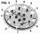
Fig. 3 is a rear view of the first embodiment of the wheel trim in its rest position or in the position when the vehicle is stopped or runs at low speed or when the brakes are a temperature higher than a preset temperature; and -
Fig. 4 is a rear view of the first embodiment of the wheel trim in its active position when the vehicle runs at high speed; -
Figs. 5 and6 are perspective views of the wheel trim according to a second embodiment in the rest and active positions, respectively; -
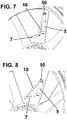
Figs. 7 and 8 are perspective views of the wheel trim according to a third embodiment in the rest and active positions, respectively; and -
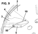
Figs. 9 and10 are perspective views of the wheel trim according to a fourth embodiment in the rest and active positions, respectively. The first, second and fourth embodiments do not fall any longer within the scope of the appended claims. The wheel trim according to the invention, identified generally bynumeral 1 , comprises abase element 2 that is fixed to a wheel (not shown) of a vehicle by a plurality ofretaining elements 9, and acover element 4 that is placed in thebase element 2 and is movable (e.g. rotatable) with respect to thisbase element 2. To permit this movement, thebase element 2 and thecover element 4 are preferably linked by a central bearing 8. - The
base element 2 comprises a plurality ofholes 3, preferably distributed around the periphery of thebase element 2, as shown inFig. 1 . - The
cover element 4 is movable between a rest position, shown inFig. 1 , in which thecover element 4 does not cover theholes 3, and an active position, shown inFig. 2 , in which thecover element 4 covers theholes 3. - It must be pointed out that the
cover element 4 can also be placed in any intermediate position between these rest and active position. However, for simplicity reasons, in this description and in the claims, the active position must be considered any position in which theholes 3 are completely or partially covered by thecover element 4. - The
cover element 4 is placed automatically in its rest position when the vehicle is stopped or runs at low speed or when the brakes are a temperature higher than a preset temperature, as will be described hereinafter. - For moving the
cover element 4, thewheel trim 1 according to the invention comprises aspeed activation element 5 that moves thecover element 4 from the rest position to the active position when the vehicle runs above a preset speed. According to alternative embodiments, thespeed activation element 5 is a spring, such as a helical metallic spring, or a gas cylinder. - The
wheel trim 1 according to the invention also comprises atemperature activation element 6 that moves thecover element 4 from the active position to the rest position when the temperature sensed by thistemperature activation element 6 is above a preset temperature. According to a preferred embodiment, thistemperature activation element 6 is a spring made from a shape memory alloy, such as a two- way shape memory alloy, i.e. a spring that can adopt two different shapes, one shape when the temperature is above a preset temperature and another shape when the temperature is below said preset temperature. - As shown in
Figs. 3 and4 , each of thespeed activation element 5 and thetemperature activation element 6 comprises two ends, a first end fixed to thebase element 2 and a second end fixed to thecover element 4, said second end being movable inside acurved groove 7 provided in thebase element 2. - In the rest position, shown in
Fig. 3 , this second end each of thespeed activation element 5 and thetemperature activation element 6 is placed in a middle portion of thegroove 7, and in the active position, shown inFig. 4 , this second end each of thespeed activation element 5 and thetemperature activation element 6 is placed in an end portion of thegroove 7. - The operation of the
activation elements - When the vehicle is stopped, the
cover element 4 is its rest position by the action of thespeed activation element 5. When the vehicle runs at a speed above a preset speed, the centrifugal force of the wheel itself will overcome the force exerted by theactivation element 5 and will be rotated to the active position, covering theholes 3. - Furthermore, when the vehicle returns to a speed below said preset speed, the
cover element 4 will return to its rest position. - In any case, if the temperature of the
temperature activation element 6 is above a preset temperature, thanks to the features of the shape memory alloy, thisactivation element 6 will move thecover element 4 to itsrest position 4, not covering theholes 3. The main reason of the increase of the temperature of thetemperature activation element 6 is the heat from the brakes of the vehicle, and theholes 3, not covered by thecover element 4 will permit the cooling of the brakes. - A second embodiment of the wheel trim is shown in
Figs. 5 and6 . For simplicity reasons the same numeral references than in the previous embodiment are used for indicating the same or equivalent elements. - In this second embodiment, the
speed activation element 5 comprises abody 50 at one of its ends, so that when the rotating speed of thewheel trim 1 is higher than a preset speed, thespeed activation element 5 moves saidcover element 4 to said active position. Thisbody 50 has a weight that is enough to permit the movement of thecover element 4 from the rest position to the active position when the vehicle runs above said preset speed. - For moving the
cover element 4, saidspeed activation element 5 is linked with thecover element 4 by anarm 10, as shown in the drawings. - A third embodiment of the wheel trim is shown in
Figs. 7 and 8 , in which each of thespeed activation element 5 and thetemperature activation element 6 comprises two ends, a first end fixed to thebase element 2 and a second end linked to thecover element 4 bysaid arm 10, being the second end of thearm 10 movable inside acurved groove 7 provided in thebase element 2. - In this embodiment, the
cover element 4 is in the face of the wheel and theactivation elements base element 2. - A fourth embodiment of the wheel trim is shown in
Figs. 9 and10 , in which theactivation elements base element 2. - Even though reference has been made to a specific embodiment of the invention, it is apparent for a person skilled in the art that the wheel trim disclosed is susceptible of numerous variations and modifications, and that all the details mentioned can be substituted by other technically equivalent ones, as long as the wheel trim does not depart from the scope of protection defined by the attached claims.
Claims (6)
- Wheel trim (1) comprising a base element (2) provided with holes (3) and a cover element (4) placed on said base element (2), the cover element (4) being linked with the base element (2) by a speed activation element (5) and said cover element (4) being movable between a rest position, in which the holes (3) are not covered by the cover element (4), and an active position, in which the holes (3) are completely or partially covered by the cover element (4), when the rotating speed of the wheel is higher than a preset speed, the cover element (4) being also linked with the base element (2) by a temperature activation element (6), so that when the temperature sensed by said temperature activation element (6) is higher than a preset temperature, the temperature activation element (6) moves the cover element (4) to said rest position,
wherein the cover element (4) is attached to the base element (2) by a central bearing (8) that permit the rotation of the cover element (4) with respect to the base element (2), and wherein the base element (2) comprises a plurality of retaining elements (9) for attaching the trim (1) to a wheel,
characterized in that a first end of the temperature activation element (6) and/or the speed activation element (5) is fixed to the base element (2) and a second end of the temperature activation element (6) and/or the speed activation element (5) is linked to the cover element (4) by an arm (10), the second end of the arm being movable inside a groove (7) provided in the base element (2). - Wheel trim (1) according to claim 1, wherein the temperature activation element (6) is a spring made of a shape memory alloy.
- Wheel trim (1) according to claim 1, wherein the speed activation element (5) is a metallic spring or a gas cylinder.
- Wheel trim (1) according to claim 1, wherein the speed activation element (5) comprises a body (50) at one of its ends, so that when the rotating speed of the wheel trim (1) is higher than a preset speed, the speed activation element (5) moves said cover element (4) to said active position.
- Wheel trim (1) according to claim 1 or 4 wherein said speed activation element (5) is linked to said cover element (4) by the arm (10).
- Wheel trim (1) according to claim 1, wherein said temperature activation element (6) is linked to said cover element (4) by the arm (10).
Applications Claiming Priority (3)
| Application Number | Priority Date | Filing Date | Title |
|---|---|---|---|
| EP14176538 | 2014-07-10 | ||
| EP15382013 | 2015-01-23 | ||
| PCT/EP2015/065850 WO2016005565A2 (en) | 2014-07-10 | 2015-07-10 | Wheel trim |
Publications (2)
| Publication Number | Publication Date |
|---|---|
| EP3166800A2 EP3166800A2 (en) | 2017-05-17 |
| EP3166800B1 true EP3166800B1 (en) | 2018-03-21 |
Family
ID=53716453
Family Applications (1)
| Application Number | Title | Priority Date | Filing Date |
|---|---|---|---|
| EP15739542.7A Not-in-force EP3166800B1 (en) | 2014-07-10 | 2015-07-10 | Wheel trim |
Country Status (7)
| Country | Link |
|---|---|
| US (1) | US10189302B2 (en) |
| EP (1) | EP3166800B1 (en) |
| JP (1) | JP2017524601A (en) |
| CN (1) | CN107074012A (en) |
| ES (1) | ES2674179T3 (en) |
| MX (1) | MX2017000350A (en) |
| WO (1) | WO2016005565A2 (en) |
Cited By (1)
| Publication number | Priority date | Publication date | Assignee | Title |
|---|---|---|---|---|
| DE102023003544A1 (en) | 2022-09-08 | 2024-03-14 | Mercedes-Benz Group AG | Variable ventilation cover for wheels |
Families Citing this family (11)
| Publication number | Priority date | Publication date | Assignee | Title |
|---|---|---|---|---|
| DE102016202483A1 (en) * | 2016-02-18 | 2017-08-24 | Continental Teves Ag & Co. Ohg | Motor vehicle wheel cover with adjusting device for a closure element for the electroless automated metered cooling air supply of a motor vehicle wheel brake |
| DE102016124121B4 (en) | 2016-12-13 | 2025-01-16 | Gv Engineering Gmbh | vehicle wheel |
| US20190322128A1 (en) * | 2018-04-18 | 2019-10-24 | GM Global Technology Operations LLC | Vehicle wheel assembly including a self-deployed wheel shutter system |
| KR102663606B1 (en) * | 2019-04-23 | 2024-05-08 | 현대자동차주식회사 | Variable aerodynamic wheel and contorl system of variable aerodynamic wheel |
| CN110802983B (en) * | 2019-11-05 | 2021-03-30 | 苏州科亿嘉新技术开发有限公司 | A kind of automobile wheel hub protection ring and its installation and use method |
| KR102609915B1 (en) * | 2022-02-04 | 2023-12-06 | 현대성우캐스팅(주) | Automobile aero wheel |
| JP7613397B2 (en) * | 2022-03-04 | 2025-01-15 | 豊田合成株式会社 | Vehicle Wheel Cover |
| CN115257662B (en) * | 2022-08-30 | 2024-01-26 | 广汽埃安新能源汽车有限公司 | Hub cover control method, device, electronic equipment and storage medium |
| KR102755392B1 (en) * | 2022-09-16 | 2025-01-21 | 인하대학교 산학협력단 | Automatic opening and closing device of car wheel spokes |
| US20250074108A1 (en) * | 2023-08-30 | 2025-03-06 | Rivian Ip Holdings, Llc | Movable wheel cover apparatus and related actuation systems for aerodynamic efficiencies |
| US20250229571A1 (en) * | 2024-01-17 | 2025-07-17 | Hyundai Motor Company | Driven aerodynamic wheel cover flap system with offset passive actuator |
Family Cites Families (14)
| Publication number | Priority date | Publication date | Assignee | Title |
|---|---|---|---|---|
| US4262967A (en) * | 1979-11-28 | 1981-04-21 | Spisak Edward G | Wheel trim retainer |
| JPH056161Y2 (en) * | 1985-06-07 | 1993-02-17 | ||
| JPH0234301U (en) * | 1988-08-31 | 1990-03-05 | ||
| JPH042503A (en) * | 1990-04-17 | 1992-01-07 | Toyoda Gosei Co Ltd | Wheel cap |
| JP3450313B2 (en) * | 2001-06-01 | 2003-09-22 | 秀和 田中 | Wheels for vehicles such as automobiles |
| EP1319526A3 (en) * | 2001-12-14 | 2005-03-16 | Bayerische Motoren Werke Aktiengesellschaft | Wheel of motor vehicle or rim |
| DE10161868A1 (en) * | 2001-12-14 | 2003-07-10 | Bayerische Motoren Werke Ag | Vehicle wheel has flaps which can be moved across to close gaps between its spokes, allowing appearance of wheel to be changed and brakes to be cooled by air flow |
| DE102008007690A1 (en) * | 2008-02-06 | 2009-08-13 | GM Global Technology Operations, Inc., Detroit | Rim or wheel attachment for a motor vehicle wheel with closable openings |
| DE102009057164A1 (en) * | 2009-12-05 | 2011-06-09 | Volkswagen Ag | Cover for covering wheel of motor vehicle, has inner part experiencing force against spring force during negative acceleration, where mutually corresponding openings of inner and outer parts are located in cover in operating position |
| DE102011016534B4 (en) * | 2010-08-16 | 2012-08-16 | Audi Ag | vehicle |
| DE102011010509A1 (en) * | 2011-02-07 | 2012-08-09 | Audi Ag | vehicle |
| DE102011016535B3 (en) * | 2011-04-08 | 2012-05-10 | Audi Ag | vehicle |
| DE102011079599B4 (en) * | 2011-07-21 | 2023-02-02 | Bayerische Motoren Werke Aktiengesellschaft | vehicle wheel |
| KR101631175B1 (en) * | 2014-11-26 | 2016-06-17 | 주식회사 코모스 | wheel cover for vehicle |
-
2015
- 2015-07-10 WO PCT/EP2015/065850 patent/WO2016005565A2/en not_active Ceased
- 2015-07-10 CN CN201580044264.XA patent/CN107074012A/en active Pending
- 2015-07-10 MX MX2017000350A patent/MX2017000350A/en unknown
- 2015-07-10 EP EP15739542.7A patent/EP3166800B1/en not_active Not-in-force
- 2015-07-10 ES ES15739542.7T patent/ES2674179T3/en active Active
- 2015-07-10 US US15/325,168 patent/US10189302B2/en not_active Expired - Fee Related
- 2015-07-10 JP JP2017521613A patent/JP2017524601A/en active Pending
Cited By (1)
| Publication number | Priority date | Publication date | Assignee | Title |
|---|---|---|---|---|
| DE102023003544A1 (en) | 2022-09-08 | 2024-03-14 | Mercedes-Benz Group AG | Variable ventilation cover for wheels |
Also Published As
| Publication number | Publication date |
|---|---|
| US20170182839A1 (en) | 2017-06-29 |
| MX2017000350A (en) | 2017-08-14 |
| WO2016005565A3 (en) | 2016-11-24 |
| US10189302B2 (en) | 2019-01-29 |
| CN107074012A (en) | 2017-08-18 |
| EP3166800A2 (en) | 2017-05-17 |
| ES2674179T3 (en) | 2018-06-27 |
| JP2017524601A (en) | 2017-08-31 |
| WO2016005565A2 (en) | 2016-01-14 |
Similar Documents
| Publication | Publication Date | Title |
|---|---|---|
| US10189302B2 (en) | Wheel trim | |
| US8801107B2 (en) | Vehicle wheel | |
| US10458496B2 (en) | Protective cover for vehicle brake | |
| JP6285978B2 (en) | Airflow control device for vehicles | |
| WO2016137856A1 (en) | Active aerodynamic vehicle wheel cover assembly, vehicle wheel assembly including such a vehicle wheel cover assembly and method for producing such a vehicle wheel assembly | |
| US10421505B2 (en) | Active deflector system for an automotive vehicle | |
| US10590799B2 (en) | Aircraft turbomachine comprising a compartment equipped with a ventilation assembly | |
| US10654531B2 (en) | Active and passive systems for wheelhouse air deflection | |
| US10744816B2 (en) | Vehicle wheel for a vehicle | |
| KR101631175B1 (en) | wheel cover for vehicle | |
| CN111169222B (en) | Rim for a vehicle | |
| MX2016007512A (en) | Underbody air and thermal management system for a motor vehicle. | |
| CN103967983A (en) | Vehicle brake cooling system | |
| MX2016004788A (en) | Ifs including control arm and strut supported by steering knuckle load arm. | |
| FR3078286A1 (en) | ACTIVE WHEEL TRIM | |
| US11667185B2 (en) | Device for ventilating a vehicle | |
| CN109305146A (en) | Active pipe-line system for motor vehicles | |
| MX368952B (en) | Strut and air spring ifs assembly maximizing available steering knuckle wheel cut. | |
| US9797463B1 (en) | Passive regulation of convective cooling | |
| JP6561701B2 (en) | Vehicle rectifier | |
| JP5895352B2 (en) | Air volume control device for automobile | |
| JP6734725B2 (en) | Air flow controller for vehicle | |
| CA2879173C (en) | Snow blower with a securing mechanism for a rotating drum | |
| US10697512B2 (en) | Articulated shield for a vehicle friction brake | |
| US12304243B2 (en) | Wheel rim assembly |
Legal Events
| Date | Code | Title | Description |
|---|---|---|---|
| STAA | Information on the status of an ep patent application or granted ep patent |
Free format text: STATUS: THE INTERNATIONAL PUBLICATION HAS BEEN MADE |
|
| PUAI | Public reference made under article 153(3) epc to a published international application that has entered the european phase |
Free format text: ORIGINAL CODE: 0009012 |
|
| STAA | Information on the status of an ep patent application or granted ep patent |
Free format text: STATUS: REQUEST FOR EXAMINATION WAS MADE |
|
| 17P | Request for examination filed |
Effective date: 20170207 |
|
| AK | Designated contracting states |
Kind code of ref document: A2 Designated state(s): AL AT BE BG CH CY CZ DE DK EE ES FI FR GB GR HR HU IE IS IT LI LT LU LV MC MK MT NL NO PL PT RO RS SE SI SK SM TR |
|
| AX | Request for extension of the european patent |
Extension state: BA ME |
|
| DAV | Request for validation of the european patent (deleted) | ||
| DAX | Request for extension of the european patent (deleted) | ||
| REG | Reference to a national code |
Ref country code: DE Ref legal event code: R079 Ref document number: 602015009170 Country of ref document: DE Free format text: PREVIOUS MAIN CLASS: B60B0007000000 Ipc: B60B0007200000 |
|
| RIC1 | Information provided on ipc code assigned before grant |
Ipc: B60B 7/20 20060101AFI20171110BHEP Ipc: B60B 7/00 20060101ALI20171110BHEP Ipc: B60B 7/04 20060101ALI20171110BHEP Ipc: B60B 7/06 20060101ALI20171110BHEP Ipc: B60B 7/10 20060101ALI20171110BHEP |
|
| GRAP | Despatch of communication of intention to grant a patent |
Free format text: ORIGINAL CODE: EPIDOSNIGR1 |
|
| STAA | Information on the status of an ep patent application or granted ep patent |
Free format text: STATUS: GRANT OF PATENT IS INTENDED |
|
| INTG | Intention to grant announced |
Effective date: 20171222 |
|
| RAP1 | Party data changed (applicant data changed or rights of an application transferred) |
Owner name: ZANINI AUTO GRUP, S.A. |
|
| GRAS | Grant fee paid |
Free format text: ORIGINAL CODE: EPIDOSNIGR3 |
|
| GRAA | (expected) grant |
Free format text: ORIGINAL CODE: 0009210 |
|
| STAA | Information on the status of an ep patent application or granted ep patent |
Free format text: STATUS: THE PATENT HAS BEEN GRANTED |
|
| AK | Designated contracting states |
Kind code of ref document: B1 Designated state(s): AL AT BE BG CH CY CZ DE DK EE ES FI FR GB GR HR HU IE IS IT LI LT LU LV MC MK MT NL NO PL PT RO RS SE SI SK SM TR |
|
| REG | Reference to a national code |
Ref country code: GB Ref legal event code: FG4D |
|
| REG | Reference to a national code |
Ref country code: CH Ref legal event code: EP |
|
| REG | Reference to a national code |
Ref country code: AT Ref legal event code: REF Ref document number: 980676 Country of ref document: AT Kind code of ref document: T Effective date: 20180415 |
|
| REG | Reference to a national code |
Ref country code: IE Ref legal event code: FG4D |
|
| REG | Reference to a national code |
Ref country code: DE Ref legal event code: R096 Ref document number: 602015009170 Country of ref document: DE |
|
| REG | Reference to a national code |
Ref country code: ES Ref legal event code: FG2A Ref document number: 2674179 Country of ref document: ES Kind code of ref document: T3 Effective date: 20180627 |
|
| REG | Reference to a national code |
Ref country code: NL Ref legal event code: MP Effective date: 20180321 |
|
| REG | Reference to a national code |
Ref country code: FR Ref legal event code: PLFP Year of fee payment: 4 |
|
| PG25 | Lapsed in a contracting state [announced via postgrant information from national office to epo] |
Ref country code: CY Free format text: LAPSE BECAUSE OF FAILURE TO SUBMIT A TRANSLATION OF THE DESCRIPTION OR TO PAY THE FEE WITHIN THE PRESCRIBED TIME-LIMIT Effective date: 20180321 Ref country code: FI Free format text: LAPSE BECAUSE OF FAILURE TO SUBMIT A TRANSLATION OF THE DESCRIPTION OR TO PAY THE FEE WITHIN THE PRESCRIBED TIME-LIMIT Effective date: 20180321 Ref country code: NO Free format text: LAPSE BECAUSE OF FAILURE TO SUBMIT A TRANSLATION OF THE DESCRIPTION OR TO PAY THE FEE WITHIN THE PRESCRIBED TIME-LIMIT Effective date: 20180621 Ref country code: HR Free format text: LAPSE BECAUSE OF FAILURE TO SUBMIT A TRANSLATION OF THE DESCRIPTION OR TO PAY THE FEE WITHIN THE PRESCRIBED TIME-LIMIT Effective date: 20180321 Ref country code: LT Free format text: LAPSE BECAUSE OF FAILURE TO SUBMIT A TRANSLATION OF THE DESCRIPTION OR TO PAY THE FEE WITHIN THE PRESCRIBED TIME-LIMIT Effective date: 20180321 |
|
| REG | Reference to a national code |
Ref country code: LT Ref legal event code: MG4D |
|
| REG | Reference to a national code |
Ref country code: AT Ref legal event code: MK05 Ref document number: 980676 Country of ref document: AT Kind code of ref document: T Effective date: 20180321 |
|
| PG25 | Lapsed in a contracting state [announced via postgrant information from national office to epo] |
Ref country code: SE Free format text: LAPSE BECAUSE OF FAILURE TO SUBMIT A TRANSLATION OF THE DESCRIPTION OR TO PAY THE FEE WITHIN THE PRESCRIBED TIME-LIMIT Effective date: 20180321 Ref country code: LV Free format text: LAPSE BECAUSE OF FAILURE TO SUBMIT A TRANSLATION OF THE DESCRIPTION OR TO PAY THE FEE WITHIN THE PRESCRIBED TIME-LIMIT Effective date: 20180321 Ref country code: BG Free format text: LAPSE BECAUSE OF FAILURE TO SUBMIT A TRANSLATION OF THE DESCRIPTION OR TO PAY THE FEE WITHIN THE PRESCRIBED TIME-LIMIT Effective date: 20180621 Ref country code: RS Free format text: LAPSE BECAUSE OF FAILURE TO SUBMIT A TRANSLATION OF THE DESCRIPTION OR TO PAY THE FEE WITHIN THE PRESCRIBED TIME-LIMIT Effective date: 20180321 Ref country code: GR Free format text: LAPSE BECAUSE OF FAILURE TO SUBMIT A TRANSLATION OF THE DESCRIPTION OR TO PAY THE FEE WITHIN THE PRESCRIBED TIME-LIMIT Effective date: 20180622 |
|
| PG25 | Lapsed in a contracting state [announced via postgrant information from national office to epo] |
Ref country code: RO Free format text: LAPSE BECAUSE OF FAILURE TO SUBMIT A TRANSLATION OF THE DESCRIPTION OR TO PAY THE FEE WITHIN THE PRESCRIBED TIME-LIMIT Effective date: 20180321 Ref country code: NL Free format text: LAPSE BECAUSE OF FAILURE TO SUBMIT A TRANSLATION OF THE DESCRIPTION OR TO PAY THE FEE WITHIN THE PRESCRIBED TIME-LIMIT Effective date: 20180321 Ref country code: EE Free format text: LAPSE BECAUSE OF FAILURE TO SUBMIT A TRANSLATION OF THE DESCRIPTION OR TO PAY THE FEE WITHIN THE PRESCRIBED TIME-LIMIT Effective date: 20180321 Ref country code: PL Free format text: LAPSE BECAUSE OF FAILURE TO SUBMIT A TRANSLATION OF THE DESCRIPTION OR TO PAY THE FEE WITHIN THE PRESCRIBED TIME-LIMIT Effective date: 20180321 Ref country code: AL Free format text: LAPSE BECAUSE OF FAILURE TO SUBMIT A TRANSLATION OF THE DESCRIPTION OR TO PAY THE FEE WITHIN THE PRESCRIBED TIME-LIMIT Effective date: 20180321 |
|
| PGFP | Annual fee paid to national office [announced via postgrant information from national office to epo] |
Ref country code: IT Payment date: 20180731 Year of fee payment: 4 Ref country code: FR Payment date: 20180726 Year of fee payment: 4 Ref country code: DE Payment date: 20180727 Year of fee payment: 4 Ref country code: ES Payment date: 20180828 Year of fee payment: 4 |
|
| PG25 | Lapsed in a contracting state [announced via postgrant information from national office to epo] |
Ref country code: SM Free format text: LAPSE BECAUSE OF FAILURE TO SUBMIT A TRANSLATION OF THE DESCRIPTION OR TO PAY THE FEE WITHIN THE PRESCRIBED TIME-LIMIT Effective date: 20180321 Ref country code: AT Free format text: LAPSE BECAUSE OF FAILURE TO SUBMIT A TRANSLATION OF THE DESCRIPTION OR TO PAY THE FEE WITHIN THE PRESCRIBED TIME-LIMIT Effective date: 20180321 Ref country code: SK Free format text: LAPSE BECAUSE OF FAILURE TO SUBMIT A TRANSLATION OF THE DESCRIPTION OR TO PAY THE FEE WITHIN THE PRESCRIBED TIME-LIMIT Effective date: 20180321 |
|
| PGFP | Annual fee paid to national office [announced via postgrant information from national office to epo] |
Ref country code: CZ Payment date: 20180719 Year of fee payment: 4 |
|
| PG25 | Lapsed in a contracting state [announced via postgrant information from national office to epo] |
Ref country code: PT Free format text: LAPSE BECAUSE OF FAILURE TO SUBMIT A TRANSLATION OF THE DESCRIPTION OR TO PAY THE FEE WITHIN THE PRESCRIBED TIME-LIMIT Effective date: 20180723 |
|
| REG | Reference to a national code |
Ref country code: DE Ref legal event code: R097 Ref document number: 602015009170 Country of ref document: DE |
|
| PLBE | No opposition filed within time limit |
Free format text: ORIGINAL CODE: 0009261 |
|
| STAA | Information on the status of an ep patent application or granted ep patent |
Free format text: STATUS: NO OPPOSITION FILED WITHIN TIME LIMIT |
|
| PG25 | Lapsed in a contracting state [announced via postgrant information from national office to epo] |
Ref country code: DK Free format text: LAPSE BECAUSE OF FAILURE TO SUBMIT A TRANSLATION OF THE DESCRIPTION OR TO PAY THE FEE WITHIN THE PRESCRIBED TIME-LIMIT Effective date: 20180321 |
|
| 26N | No opposition filed |
Effective date: 20190102 |
|
| REG | Reference to a national code |
Ref country code: CH Ref legal event code: PL |
|
| PG25 | Lapsed in a contracting state [announced via postgrant information from national office to epo] |
Ref country code: LU Free format text: LAPSE BECAUSE OF NON-PAYMENT OF DUE FEES Effective date: 20180710 Ref country code: MC Free format text: LAPSE BECAUSE OF FAILURE TO SUBMIT A TRANSLATION OF THE DESCRIPTION OR TO PAY THE FEE WITHIN THE PRESCRIBED TIME-LIMIT Effective date: 20180321 |
|
| REG | Reference to a national code |
Ref country code: BE Ref legal event code: MM Effective date: 20180731 |
|
| REG | Reference to a national code |
Ref country code: IE Ref legal event code: MM4A |
|
| PG25 | Lapsed in a contracting state [announced via postgrant information from national office to epo] |
Ref country code: CH Free format text: LAPSE BECAUSE OF NON-PAYMENT OF DUE FEES Effective date: 20180731 Ref country code: LI Free format text: LAPSE BECAUSE OF NON-PAYMENT OF DUE FEES Effective date: 20180731 Ref country code: IE Free format text: LAPSE BECAUSE OF NON-PAYMENT OF DUE FEES Effective date: 20180710 |
|
| PG25 | Lapsed in a contracting state [announced via postgrant information from national office to epo] |
Ref country code: SI Free format text: LAPSE BECAUSE OF FAILURE TO SUBMIT A TRANSLATION OF THE DESCRIPTION OR TO PAY THE FEE WITHIN THE PRESCRIBED TIME-LIMIT Effective date: 20180321 Ref country code: BE Free format text: LAPSE BECAUSE OF NON-PAYMENT OF DUE FEES Effective date: 20180731 |
|
| REG | Reference to a national code |
Ref country code: DE Ref legal event code: R082 Ref document number: 602015009170 Country of ref document: DE |
|
| PG25 | Lapsed in a contracting state [announced via postgrant information from national office to epo] |
Ref country code: MT Free format text: LAPSE BECAUSE OF NON-PAYMENT OF DUE FEES Effective date: 20180710 Ref country code: CZ Free format text: LAPSE BECAUSE OF NON-PAYMENT OF DUE FEES Effective date: 20190710 |
|
| REG | Reference to a national code |
Ref country code: DE Ref legal event code: R119 Ref document number: 602015009170 Country of ref document: DE |
|
| GBPC | Gb: european patent ceased through non-payment of renewal fee |
Effective date: 20190710 |
|
| PG25 | Lapsed in a contracting state [announced via postgrant information from national office to epo] |
Ref country code: TR Free format text: LAPSE BECAUSE OF FAILURE TO SUBMIT A TRANSLATION OF THE DESCRIPTION OR TO PAY THE FEE WITHIN THE PRESCRIBED TIME-LIMIT Effective date: 20180321 |
|
| PG25 | Lapsed in a contracting state [announced via postgrant information from national office to epo] |
Ref country code: GB Free format text: LAPSE BECAUSE OF NON-PAYMENT OF DUE FEES Effective date: 20190710 Ref country code: DE Free format text: LAPSE BECAUSE OF NON-PAYMENT OF DUE FEES Effective date: 20200201 |
|
| PG25 | Lapsed in a contracting state [announced via postgrant information from national office to epo] |
Ref country code: FR Free format text: LAPSE BECAUSE OF NON-PAYMENT OF DUE FEES Effective date: 20190731 Ref country code: MK Free format text: LAPSE BECAUSE OF NON-PAYMENT OF DUE FEES Effective date: 20180321 Ref country code: HU Free format text: LAPSE BECAUSE OF FAILURE TO SUBMIT A TRANSLATION OF THE DESCRIPTION OR TO PAY THE FEE WITHIN THE PRESCRIBED TIME-LIMIT; INVALID AB INITIO Effective date: 20150710 |
|
| PG25 | Lapsed in a contracting state [announced via postgrant information from national office to epo] |
Ref country code: IS Free format text: LAPSE BECAUSE OF FAILURE TO SUBMIT A TRANSLATION OF THE DESCRIPTION OR TO PAY THE FEE WITHIN THE PRESCRIBED TIME-LIMIT Effective date: 20180721 |
|
| PG25 | Lapsed in a contracting state [announced via postgrant information from national office to epo] |
Ref country code: IT Free format text: LAPSE BECAUSE OF NON-PAYMENT OF DUE FEES Effective date: 20190710 |
|
| REG | Reference to a national code |
Ref country code: ES Ref legal event code: FD2A Effective date: 20201126 |
|
| PG25 | Lapsed in a contracting state [announced via postgrant information from national office to epo] |
Ref country code: ES Free format text: LAPSE BECAUSE OF NON-PAYMENT OF DUE FEES Effective date: 20190711 |