EP3166787B1 - Thinwall composites for electronic enclosures and other devices - Google Patents
Thinwall composites for electronic enclosures and other devices Download PDFInfo
- Publication number
- EP3166787B1 EP3166787B1 EP15760240.0A EP15760240A EP3166787B1 EP 3166787 B1 EP3166787 B1 EP 3166787B1 EP 15760240 A EP15760240 A EP 15760240A EP 3166787 B1 EP3166787 B1 EP 3166787B1
- Authority
- EP
- European Patent Office
- Prior art keywords
- vol
- equal
- thermoplastic material
- core layer
- reinforcing material
- Prior art date
- Legal status (The legal status is an assumption and is not a legal conclusion. Google has not performed a legal analysis and makes no representation as to the accuracy of the status listed.)
- Active
Links
Images





Classifications
-
- B—PERFORMING OPERATIONS; TRANSPORTING
- B32—LAYERED PRODUCTS
- B32B—LAYERED PRODUCTS, i.e. PRODUCTS BUILT-UP OF STRATA OF FLAT OR NON-FLAT, e.g. CELLULAR OR HONEYCOMB, FORM
- B32B27/00—Layered products comprising a layer of synthetic resin
- B32B27/12—Layered products comprising a layer of synthetic resin next to a fibrous or filamentary layer
-
- B—PERFORMING OPERATIONS; TRANSPORTING
- B32—LAYERED PRODUCTS
- B32B—LAYERED PRODUCTS, i.e. PRODUCTS BUILT-UP OF STRATA OF FLAT OR NON-FLAT, e.g. CELLULAR OR HONEYCOMB, FORM
- B32B27/00—Layered products comprising a layer of synthetic resin
- B32B27/06—Layered products comprising a layer of synthetic resin as the main or only constituent of a layer, which is next to another layer of the same or of a different material
- B32B27/08—Layered products comprising a layer of synthetic resin as the main or only constituent of a layer, which is next to another layer of the same or of a different material of synthetic resin
-
- B—PERFORMING OPERATIONS; TRANSPORTING
- B29—WORKING OF PLASTICS; WORKING OF SUBSTANCES IN A PLASTIC STATE IN GENERAL
- B29C—SHAPING OR JOINING OF PLASTICS; SHAPING OF MATERIAL IN A PLASTIC STATE, NOT OTHERWISE PROVIDED FOR; AFTER-TREATMENT OF THE SHAPED PRODUCTS, e.g. REPAIRING
- B29C45/00—Injection moulding, i.e. forcing the required volume of moulding material through a nozzle into a closed mould; Apparatus therefor
- B29C45/14—Injection moulding, i.e. forcing the required volume of moulding material through a nozzle into a closed mould; Apparatus therefor incorporating preformed parts or layers, e.g. injection moulding around inserts or for coating articles
- B29C45/14467—Joining articles or parts of a single article
- B29C45/14508—Joining juxtaposed sheet-like articles, e.g. for making trim panels
-
- B—PERFORMING OPERATIONS; TRANSPORTING
- B32—LAYERED PRODUCTS
- B32B—LAYERED PRODUCTS, i.e. PRODUCTS BUILT-UP OF STRATA OF FLAT OR NON-FLAT, e.g. CELLULAR OR HONEYCOMB, FORM
- B32B1/00—Layered products having a non-planar shape
-
- B—PERFORMING OPERATIONS; TRANSPORTING
- B32—LAYERED PRODUCTS
- B32B—LAYERED PRODUCTS, i.e. PRODUCTS BUILT-UP OF STRATA OF FLAT OR NON-FLAT, e.g. CELLULAR OR HONEYCOMB, FORM
- B32B27/00—Layered products comprising a layer of synthetic resin
- B32B27/18—Layered products comprising a layer of synthetic resin characterised by the use of special additives
- B32B27/20—Layered products comprising a layer of synthetic resin characterised by the use of special additives using fillers, pigments, thixotroping agents
-
- B—PERFORMING OPERATIONS; TRANSPORTING
- B32—LAYERED PRODUCTS
- B32B—LAYERED PRODUCTS, i.e. PRODUCTS BUILT-UP OF STRATA OF FLAT OR NON-FLAT, e.g. CELLULAR OR HONEYCOMB, FORM
- B32B27/00—Layered products comprising a layer of synthetic resin
- B32B27/28—Layered products comprising a layer of synthetic resin comprising synthetic resins not wholly covered by any one of the sub-groups B32B27/30 - B32B27/42
- B32B27/281—Layered products comprising a layer of synthetic resin comprising synthetic resins not wholly covered by any one of the sub-groups B32B27/30 - B32B27/42 comprising polyimides
-
- B—PERFORMING OPERATIONS; TRANSPORTING
- B32—LAYERED PRODUCTS
- B32B—LAYERED PRODUCTS, i.e. PRODUCTS BUILT-UP OF STRATA OF FLAT OR NON-FLAT, e.g. CELLULAR OR HONEYCOMB, FORM
- B32B27/00—Layered products comprising a layer of synthetic resin
- B32B27/28—Layered products comprising a layer of synthetic resin comprising synthetic resins not wholly covered by any one of the sub-groups B32B27/30 - B32B27/42
- B32B27/286—Layered products comprising a layer of synthetic resin comprising synthetic resins not wholly covered by any one of the sub-groups B32B27/30 - B32B27/42 comprising polysulphones; polysulfides
-
- B—PERFORMING OPERATIONS; TRANSPORTING
- B32—LAYERED PRODUCTS
- B32B—LAYERED PRODUCTS, i.e. PRODUCTS BUILT-UP OF STRATA OF FLAT OR NON-FLAT, e.g. CELLULAR OR HONEYCOMB, FORM
- B32B27/00—Layered products comprising a layer of synthetic resin
- B32B27/28—Layered products comprising a layer of synthetic resin comprising synthetic resins not wholly covered by any one of the sub-groups B32B27/30 - B32B27/42
- B32B27/288—Layered products comprising a layer of synthetic resin comprising synthetic resins not wholly covered by any one of the sub-groups B32B27/30 - B32B27/42 comprising polyketones
-
- B—PERFORMING OPERATIONS; TRANSPORTING
- B32—LAYERED PRODUCTS
- B32B—LAYERED PRODUCTS, i.e. PRODUCTS BUILT-UP OF STRATA OF FLAT OR NON-FLAT, e.g. CELLULAR OR HONEYCOMB, FORM
- B32B27/00—Layered products comprising a layer of synthetic resin
- B32B27/32—Layered products comprising a layer of synthetic resin comprising polyolefins
-
- B—PERFORMING OPERATIONS; TRANSPORTING
- B32—LAYERED PRODUCTS
- B32B—LAYERED PRODUCTS, i.e. PRODUCTS BUILT-UP OF STRATA OF FLAT OR NON-FLAT, e.g. CELLULAR OR HONEYCOMB, FORM
- B32B27/00—Layered products comprising a layer of synthetic resin
- B32B27/34—Layered products comprising a layer of synthetic resin comprising polyamides
-
- B—PERFORMING OPERATIONS; TRANSPORTING
- B32—LAYERED PRODUCTS
- B32B—LAYERED PRODUCTS, i.e. PRODUCTS BUILT-UP OF STRATA OF FLAT OR NON-FLAT, e.g. CELLULAR OR HONEYCOMB, FORM
- B32B27/00—Layered products comprising a layer of synthetic resin
- B32B27/36—Layered products comprising a layer of synthetic resin comprising polyesters
-
- B—PERFORMING OPERATIONS; TRANSPORTING
- B32—LAYERED PRODUCTS
- B32B—LAYERED PRODUCTS, i.e. PRODUCTS BUILT-UP OF STRATA OF FLAT OR NON-FLAT, e.g. CELLULAR OR HONEYCOMB, FORM
- B32B27/00—Layered products comprising a layer of synthetic resin
- B32B27/36—Layered products comprising a layer of synthetic resin comprising polyesters
- B32B27/365—Layered products comprising a layer of synthetic resin comprising polyesters comprising polycarbonates
-
- B—PERFORMING OPERATIONS; TRANSPORTING
- B32—LAYERED PRODUCTS
- B32B—LAYERED PRODUCTS, i.e. PRODUCTS BUILT-UP OF STRATA OF FLAT OR NON-FLAT, e.g. CELLULAR OR HONEYCOMB, FORM
- B32B5/00—Layered products characterised by the non- homogeneity or physical structure, i.e. comprising a fibrous, filamentary, particulate or foam layer; Layered products characterised by having a layer differing constitutionally or physically in different parts
- B32B5/02—Layered products characterised by the non- homogeneity or physical structure, i.e. comprising a fibrous, filamentary, particulate or foam layer; Layered products characterised by having a layer differing constitutionally or physically in different parts characterised by structural features of a fibrous or filamentary layer
- B32B5/024—Woven fabric
-
- B—PERFORMING OPERATIONS; TRANSPORTING
- B32—LAYERED PRODUCTS
- B32B—LAYERED PRODUCTS, i.e. PRODUCTS BUILT-UP OF STRATA OF FLAT OR NON-FLAT, e.g. CELLULAR OR HONEYCOMB, FORM
- B32B7/00—Layered products characterised by the relation between layers; Layered products characterised by the relative orientation of features between layers, or by the relative values of a measurable parameter between layers, i.e. products comprising layers having different physical, chemical or physicochemical properties; Layered products characterised by the interconnection of layers
- B32B7/02—Physical, chemical or physicochemical properties
-
- G—PHYSICS
- G06—COMPUTING OR CALCULATING; COUNTING
- G06F—ELECTRIC DIGITAL DATA PROCESSING
- G06F1/00—Details not covered by groups G06F3/00 - G06F13/00 and G06F21/00
- G06F1/16—Constructional details or arrangements
- G06F1/1613—Constructional details or arrangements for portable computers
- G06F1/1633—Constructional details or arrangements of portable computers not specific to the type of enclosures covered by groups G06F1/1615 - G06F1/1626
-
- B—PERFORMING OPERATIONS; TRANSPORTING
- B29—WORKING OF PLASTICS; WORKING OF SUBSTANCES IN A PLASTIC STATE IN GENERAL
- B29K—INDEXING SCHEME ASSOCIATED WITH SUBCLASSES B29B, B29C OR B29D, RELATING TO MOULDING MATERIALS OR TO MATERIALS FOR MOULDS, REINFORCEMENTS, FILLERS OR PREFORMED PARTS, e.g. INSERTS
- B29K2069/00—Use of PC, i.e. polycarbonates or derivatives thereof, as moulding material
-
- B—PERFORMING OPERATIONS; TRANSPORTING
- B29—WORKING OF PLASTICS; WORKING OF SUBSTANCES IN A PLASTIC STATE IN GENERAL
- B29K—INDEXING SCHEME ASSOCIATED WITH SUBCLASSES B29B, B29C OR B29D, RELATING TO MOULDING MATERIALS OR TO MATERIALS FOR MOULDS, REINFORCEMENTS, FILLERS OR PREFORMED PARTS, e.g. INSERTS
- B29K2309/00—Use of inorganic materials not provided for in groups B29K2303/00 - B29K2307/00, as reinforcement
- B29K2309/08—Glass
-
- B—PERFORMING OPERATIONS; TRANSPORTING
- B29—WORKING OF PLASTICS; WORKING OF SUBSTANCES IN A PLASTIC STATE IN GENERAL
- B29K—INDEXING SCHEME ASSOCIATED WITH SUBCLASSES B29B, B29C OR B29D, RELATING TO MOULDING MATERIALS OR TO MATERIALS FOR MOULDS, REINFORCEMENTS, FILLERS OR PREFORMED PARTS, e.g. INSERTS
- B29K2713/00—Use of textile products or fabrics for preformed parts, e.g. for inserts
-
- B—PERFORMING OPERATIONS; TRANSPORTING
- B29—WORKING OF PLASTICS; WORKING OF SUBSTANCES IN A PLASTIC STATE IN GENERAL
- B29L—INDEXING SCHEME ASSOCIATED WITH SUBCLASS B29C, RELATING TO PARTICULAR ARTICLES
- B29L2031/00—Other particular articles
- B29L2031/34—Electrical apparatus, e.g. sparking plugs or parts thereof
- B29L2031/3481—Housings or casings incorporating or embedding electric or electronic elements
-
- B—PERFORMING OPERATIONS; TRANSPORTING
- B32—LAYERED PRODUCTS
- B32B—LAYERED PRODUCTS, i.e. PRODUCTS BUILT-UP OF STRATA OF FLAT OR NON-FLAT, e.g. CELLULAR OR HONEYCOMB, FORM
- B32B2250/00—Layers arrangement
- B32B2250/03—3 layers
-
- B—PERFORMING OPERATIONS; TRANSPORTING
- B32—LAYERED PRODUCTS
- B32B—LAYERED PRODUCTS, i.e. PRODUCTS BUILT-UP OF STRATA OF FLAT OR NON-FLAT, e.g. CELLULAR OR HONEYCOMB, FORM
- B32B2250/00—Layers arrangement
- B32B2250/24—All layers being polymeric
-
- B—PERFORMING OPERATIONS; TRANSPORTING
- B32—LAYERED PRODUCTS
- B32B—LAYERED PRODUCTS, i.e. PRODUCTS BUILT-UP OF STRATA OF FLAT OR NON-FLAT, e.g. CELLULAR OR HONEYCOMB, FORM
- B32B2250/00—Layers arrangement
- B32B2250/40—Symmetrical or sandwich layers, e.g. ABA, ABCBA, ABCCBA
-
- B—PERFORMING OPERATIONS; TRANSPORTING
- B32—LAYERED PRODUCTS
- B32B—LAYERED PRODUCTS, i.e. PRODUCTS BUILT-UP OF STRATA OF FLAT OR NON-FLAT, e.g. CELLULAR OR HONEYCOMB, FORM
- B32B2260/00—Layered product comprising an impregnated, embedded, or bonded layer wherein the layer comprises an impregnation, embedding, or binder material
- B32B2260/02—Composition of the impregnated, bonded or embedded layer
- B32B2260/021—Fibrous or filamentary layer
- B32B2260/023—Two or more layers
-
- B—PERFORMING OPERATIONS; TRANSPORTING
- B32—LAYERED PRODUCTS
- B32B—LAYERED PRODUCTS, i.e. PRODUCTS BUILT-UP OF STRATA OF FLAT OR NON-FLAT, e.g. CELLULAR OR HONEYCOMB, FORM
- B32B2260/00—Layered product comprising an impregnated, embedded, or bonded layer wherein the layer comprises an impregnation, embedding, or binder material
- B32B2260/04—Impregnation, embedding, or binder material
- B32B2260/046—Synthetic resin
-
- B—PERFORMING OPERATIONS; TRANSPORTING
- B32—LAYERED PRODUCTS
- B32B—LAYERED PRODUCTS, i.e. PRODUCTS BUILT-UP OF STRATA OF FLAT OR NON-FLAT, e.g. CELLULAR OR HONEYCOMB, FORM
- B32B2262/00—Composition or structural features of fibres which form a fibrous or filamentary layer or are present as additives
- B32B2262/10—Inorganic fibres
-
- B—PERFORMING OPERATIONS; TRANSPORTING
- B32—LAYERED PRODUCTS
- B32B—LAYERED PRODUCTS, i.e. PRODUCTS BUILT-UP OF STRATA OF FLAT OR NON-FLAT, e.g. CELLULAR OR HONEYCOMB, FORM
- B32B2262/00—Composition or structural features of fibres which form a fibrous or filamentary layer or are present as additives
- B32B2262/10—Inorganic fibres
- B32B2262/101—Glass fibres
-
- B—PERFORMING OPERATIONS; TRANSPORTING
- B32—LAYERED PRODUCTS
- B32B—LAYERED PRODUCTS, i.e. PRODUCTS BUILT-UP OF STRATA OF FLAT OR NON-FLAT, e.g. CELLULAR OR HONEYCOMB, FORM
- B32B2262/00—Composition or structural features of fibres which form a fibrous or filamentary layer or are present as additives
- B32B2262/10—Inorganic fibres
- B32B2262/106—Carbon fibres, e.g. graphite fibres
-
- B—PERFORMING OPERATIONS; TRANSPORTING
- B32—LAYERED PRODUCTS
- B32B—LAYERED PRODUCTS, i.e. PRODUCTS BUILT-UP OF STRATA OF FLAT OR NON-FLAT, e.g. CELLULAR OR HONEYCOMB, FORM
- B32B2262/00—Composition or structural features of fibres which form a fibrous or filamentary layer or are present as additives
- B32B2262/14—Mixture of at least two fibres made of different materials
-
- B—PERFORMING OPERATIONS; TRANSPORTING
- B32—LAYERED PRODUCTS
- B32B—LAYERED PRODUCTS, i.e. PRODUCTS BUILT-UP OF STRATA OF FLAT OR NON-FLAT, e.g. CELLULAR OR HONEYCOMB, FORM
- B32B2307/00—Properties of the layers or laminate
- B32B2307/30—Properties of the layers or laminate having particular thermal properties
- B32B2307/302—Conductive
-
- B—PERFORMING OPERATIONS; TRANSPORTING
- B32—LAYERED PRODUCTS
- B32B—LAYERED PRODUCTS, i.e. PRODUCTS BUILT-UP OF STRATA OF FLAT OR NON-FLAT, e.g. CELLULAR OR HONEYCOMB, FORM
- B32B2307/00—Properties of the layers or laminate
- B32B2307/70—Other properties
- B32B2307/72—Density
-
- B—PERFORMING OPERATIONS; TRANSPORTING
- B32—LAYERED PRODUCTS
- B32B—LAYERED PRODUCTS, i.e. PRODUCTS BUILT-UP OF STRATA OF FLAT OR NON-FLAT, e.g. CELLULAR OR HONEYCOMB, FORM
- B32B2307/00—Properties of the layers or laminate
- B32B2307/70—Other properties
- B32B2307/732—Dimensional properties
-
- B—PERFORMING OPERATIONS; TRANSPORTING
- B32—LAYERED PRODUCTS
- B32B—LAYERED PRODUCTS, i.e. PRODUCTS BUILT-UP OF STRATA OF FLAT OR NON-FLAT, e.g. CELLULAR OR HONEYCOMB, FORM
- B32B2457/00—Electrical equipment
Definitions
- Housings for electronic devices can benefit from certain mechanical properties. For example, industry trends benefit from housings that are thin, light-weight, and can be manufactured at low cost. In an attempt to meet industry demand, a variety of materials are used for electronic device housings. However, efforts to make thinner and lighter housings using different materials and production methods have resulted in undesirable performance and cost tradeoffs.
- U.S. Patent No. 8,372,495 discloses a housing for an electronic device or other object formed in a layered configuration.
- the layer or sandwich construction imparts strength and rigidity while decreasing the overall weight to the housing.
- the case/housing may have a first layer and a second layer formed from a first material.
- the case may also include a core formed from a second material. Where the first layer may be bonded to a top surface of the core and the second layer may be bonded to a bottom surface of the core.
- US 2010/040902 A1 discloses light-weight composite materials, which can be processed to form an outer covering layer, comprising a metallic layer and a polymeric layer, the polymeric layer containing a filled thermoplastic polymer which includes a thermoplastic polymer and a metallic fiber.
- JP 2014127518 A discloses a heat dissipation film consisting of a heat transfer layer containing graphene fine grain and a binder resin, and a plastic film bonded to at least one side of the
- WO2013070447 discloses a photovoltaic module, comprising a transparent superstrate; a backsheet, wherein the backsheet comprises a core layer comprising a core composition formed from a first polycarbonate comprising dimethyl bisphenol cyclohexane carbonate repeat units and bisphenol-A, wherein the first polycarbonate has the structure wherein the dimethyl bisphenol cyclohexane carbonate repeat units are present in an amount of 10 wt.% to 50 wt.%, based on the total repeat units in the core composition; and a second polycarbonate selected from the group consisting of a bisphenol-A polycarbonate homopolymer, a polyphthalate carbonate copolymer, polycarbonate copolymer comprising 2-phenyl-3,3-bis(4-hydroxyphenyl) phthalimidine carbonate and bisphenol-A carbonate repeat units, a polycarbonate copolymer comprising bisphenol-A carbonate and tetrabromobisphenol A carbonate repeat units, and
- A-B-A structures Disclosed herein are A-B-A structures, housings comprising the structures, and methods of making the same, in accordance with claims 1, 13, 12 and 14, respectively.
- the A-B-A structure comprising: a core layer comprising a first thermoplastic material having a first density (Y), wherein the core layer has a core thickness and wherein the core layer comprisea through plane thermal conductivity of greater than equal to 0.1 W/mK,wherein thermal conductivity is determined in accordance with ASTM E1461 using laser flash method, wherein test specimens were cut into 10x10x3 mm square samples from an injection molded 80x10x3 mm IZOD bar, anda core layer density (X) that is X > 0.8Y; a first outer layer comprising a second thermoplastic material located on a first side of the core layer; anda second outer layer comprising the second thermoplastic material located on a second side of the core layer opposite the first side;wherein the core thickness is 30 % to 75% of a total thickness, or 40 % to 60% of a total thickness, or 45 % to 55% of a total thickness, or 55 % to 70 % of a total thickness of the A-B-
- A-B-A structures Disclosed herein are A-B-A structures, housings (e.g., for electronic devices), and methods of making the same.
- WO2013070447 does not disclose or suggest the use of a sandwich construction for an electronic device housing. Thus, WO2013070447 does not identify or solve the problem of producing a light-weight, thin enclosure that can meet the mechanical requirements of a housing for an electronic device.
- U.S. Patent No. 8,372,495 discloses the use of a sandwich construction including a unidirectional carbon fiber reinforced polymer (CFRP) skin and a lower density core.
- CFRP materials generally do not resist bending or stresses applied in a direction transverse to the length of the carbon fibers.
- sandwich skins produced from unidirectional CFRP must be layered to produce quasi-isotropic constructions. Layered CFRP skins add to the cost, complexity and thickness of the sandwich construction.
- U.S. Patent No. 8,373,495 describes low density cores made from foam or honeycomb structures. The thermal conductivity and diffusivity of these cores are much lower than a solid structure because a large portion of core volume consists of air.
- Foams and honeycomb structures have a thermal conductivity that can be less than 0.02 watts per meter kelvin (W/mK). Lower wall conductivity leads to higher internal temperatures, which is an undesirable effect for an electronic device housing.
- skin adhesion for a foam or honeycomb core is limited by the small area of contact between the skin and honeycomb. Sandwich constructions that are produced using low density foam or honeycomb cores have two other mechanical shortcomings. The first is related to lowered resistance to local penetration. For example, sharp local loads are resisted largely by the skins, and the core does not add significantly to penetration resistance. Second, sandwich constructions built with foam or honeycomb cores fail in compression when placed in flexure. The foam or honeycomb collapses underneath the skin before skin failure stresses are reached. Thus, failure strains for sandwich constructions with foam or honeycomb cores are lower than those that would occur if a solid core is used.
- the featured A-B-A structures, housings, and methods of making described here provide light weight, thin-walled structures with high stiffness, high thermal conductivity, high flexural strength, and high peel strength.
- the A-B-A structure comprises a first thermoplastic material; a first outer layer comprising a second thermoplastic material located on a first side of the core layer and in physical contact therewith; a second outer layer comprising the second thermoplastic material located on a second side of the core layer opposite the first side and in physical contact with the core layer; wherein the core layer has a through plane thermal conductivity of greater than equal to 0.1 Watts per meter-Kelvin (W/mK); wherein the thickness of the core layer is 30% to 75% of the total thickness of the A-B-A structure.
- W/mK Watts per meter-Kelvin
- a housing according to the present invention comprises the A-B-A structure with a frame disposed around the structure, also optionally attached to the frame can be rib(s) and/or attachment features. If the housing is used for an electronic device, the housing can further comprise a backing, wherein the backing connects to the A-B-A structure via attachment features on the frame, and wherein electronic components can be located between the A-B-A structure and the backing.
- a housing for an electronic device comprises the A-B-A structure.
- This disclosure relates to an A-B-A structure, a housing comprising the A-B-A structure, and methods of making the same.
- a thin-walled A-B-A structure including a thermoplastic composite construction.
- the composite construction preferably includes a sandwich construction including outer layers of reinforced material with an inner core of a thermoplastic material which may or may not be reinforced.
- the inner core can be a solid thermoplastic material or a substantially solid thermoplastic material.
- continuously reinforced thermoplastic "through thickness" composites continuous reinforced layer(s) of one composition throughout
- Fabric reinforced systems offer benefits in mechanical properties (e.g., stiffness, strength, and in-plane isotropy) and formability.
- mechanical properties e.g., stiffness, strength, and in-plane isotropy
- formability e.g., stiffness, strength, and in-plane isotropy
- two factors have limited the use of these materials in enclosures.
- the cost of continuously reinforced systems is 4 to 5 times greater than the highest performance short carbon filled thermoplastics.
- full "through thickness” multilayer composite laminates in other words, continuous reinforcement throughout; i.e., the same material in all layers
- these materials can be thermoset materials similar to those used in the aerospace industry.
- the performance benefits of these stiff lightweight structures are outweighed by material costs and time consuming manufacturing methods. This combination of factors has limited their use in the broader enclosure market.
- Some manufacturers have adopted machined aluminum as a material solution. However, this approach is suffers the same drawbacks as the "through thickness" laminates.
- Glass, carbon and alternative short fiber reinforcements have been used to form enclosures, but the trend toward thinner wall thicknesses (e.g., less than 1.0 millimeter (mm)) creates challenging processing conditions. This is compounded by the fact that thinner walls require higher mechanical properties, which means higher reinforcement loadings to attain stiffer/high aspect ratio reinforcements.
- These specialty short fiber reinforced compounds have high melt viscosities which make them challenging to mold.
- high aspect ratio reinforcements result in higher than normal flow induced fiber orientation and (therefore) mechanical performance variability.
- Manufacturers of notebooks, notepads and smartphones are actively searching for materials that offer better mechanical properties, lower levels of in-plane anisotropy, and unobstructed package spaces.
- honeycomb or other low density foam structures between skin layers, wherein the skin layers form a total of less than or equal to 10% of the thickness of the total structure.
- these laminates exhibit low peel strength (typically less than 10 in-lb/in (1750 newton/meter) but occasionally up to 25 in-lb/in (4400 newton/meter) (depending on materials) because the skin layers are not in constant contact with the lightweight cores. For example, the gaps between the walls of the honeycomb structure are not in contact with the skin layer.
- these laminates have a lower thermal conductivity and diffusivity than a solid structure of the same material.
- low density cores such as honeycomb and foam result in lowered resistance to local penetration. This is an especially important attribute for electrical enclosures where exposure of internal wiring and circuitry may pose a safety risk.
- structures built using low density cores rarely achieve their maximum theoretical mechanical capabilities because the cores will fail in compression prior to skin rupture.
- housings for electronic devices that are thin, low weight (as compared to a through thickness structure having the same stiffness and using the same materials, has a weight that is greater than or equal to 12%, e.g., greater than or equal to 15% lighter than a through thickness structure), cost effective, and possess suitable thermal conductivity and mechanical properties.
- More beneficial approaches described here include thin-walled housings for electronic devices and methods of making the same. It is believed that the favorable results obtained herein (e.g., a thin, low weight, high strength A-B-A structure), can be achieved through a sandwich construction including a thermoplastic core (e.g., a solid thermoplastic core) between thermoplastic composite outer layers. Specific parametric maxima and minima are disclosed to highlight certain examples with desirable performance.
- the A-B-A structure disclosed herein are A-B-A sandwich constructions in which an "A" material forms a first outer layer and a second outer layer located on opposite sides of a solid core layer formed from a "B" material.
- the solid core can include a first thermoplastic material and the first outer layer and second outer layer can include a second thermoplastic material.
- the first and second thermoplastic materials are compatible (and hence adhere to each other). These materials can be the same type of thermoplastic material, with different viscosities (e.g., having different molecular weights and/or having different reinforcement loadings).
- the A-B-A structure can utilize highly filled (e.g., greater than or equal to 35 volume percent (vol.%), e.g., 35 vol.% to 70 vol.% reinforcing material, based upon the total volume of the outer layer) outer layers ("A").
- the outer layers can be continuously reinforced, e.g., can comprise a fiber that was produced in a continuous form.
- the overall thickness of the A-B-A structure can be less than or equal to 1.6 millimeters (mm), for example, less than or equal to 1.5 mm, or less than or equal to 1.25 mm, or less than or equal to 1.0 mm.
- the overall thickness of the A-B-A structure can be 0.5 mm to 1.5 mm, for example 0.5 mm to 1.25 mm, or 0.75 mm to 1.1 mm.
- the core layer has a core thickness (t c ) of 30 % to 75% of the total thickness of the A-B-A structure.
- the core layer can include 40 % to 60% of the total thickness of the A-B-A structure.
- the core layer can include 45 % to 55% of the total thickness of the A-B-A structure.
- the core layer can include 55 % to 70 % of the total thickness of the A-B-A structure.
- the flexural modulus of the A-B-A structure can be greater than or equal to 2,000,000 pounds per square inch (psi) (13.8 GigaPascals (GPa)), for example, greater than or equal to 5,000,000 psi (34.5GPa).
- the housing can comprise a frame that can be located about a periphery of at least a portion of the A-B-A structure.
- the frame can include a material that is compatible with the A-B-A structure, and desirably, a material that minimally changes the shape of the A-B-A structure before (initial shape) and after (final shape) the frame is attached (e.g., the change from initial shape to final shape is a bowing of less than or equal to 2 mm, specifically less than or equal to 1 mm, or less than or equal to 0.2 mm, or no change).
- the A-B-A structure is flat (no curvature)
- the change from flat e.g.
- the separation from a flat surface is less than or equal to 2 mm, specifically less than or equal to 1 mm, or less than or equal to 0.2 mm, or no separation (measurable without a microscope).
- there is no change in the shape of the A-B-A structure e.g. a deflection from initial shape to final shape of 0%.
- the frame can include a material that has a coefficient of thermal expansion that differs from the coefficient of thermal expansion of the A-B-A laminate such that, before the frame is attached and after the frame has been molded onto the A-B-A laminate, the A-B-A laminate remains flat.
- the frame can comprise a thermoplastic material (e.g., the first thermoplastic material or the second thermoplastic material) and reinforcement (e.g., filler or reinforcing material).
- reinforcements include fibers (e.g., short fibers (such as fibers having a length of less than or equal to 10 mm).
- the reinforcement material can be any of the materials used for the filler or reinforcing material in the A-B-A structure as described below.
- the reinforcement can comprise high stiffness inorganic fibers (e.g., glass, carbon, quartz, boron, and combinations comprising at least one of the foregoing), wherein high stiffness refers to a tensile modulus of greater than or equal to 35 GPa, for example, a tensile modulus of greater than or equal to 45 GPa.
- high stiffness refers to a tensile modulus of greater than or equal to 35 GPa, for example, a tensile modulus of greater than or equal to 45 GPa.
- the frame can be a metallic frame, such as magnesium or aluminum.
- the frame can be a tube of metallic material that is perforated to encourage mechanical adhesion to the A-B-A structure (e.g., to the first and/or second material).
- the frame can have a thickness greater than the thickness of the A-B-A laminate (e.g., as measured from the outer surface of one A layer to the outer surface of the other A layer).
- the frame can have a thickness less than or equal to the thickness of the A-B-A laminate.
- the frame can allow for the inclusion of attachment features, ribs, and corner radii.
- the core layer can have a thermal conductivity that enables the dissipation of heat from the electronic device.
- the first thermoplastic material can have a through plane thermal conductivity of greater than or equal to 0.1 W/mK.
- Thermal conductivity is determined in accordance with ASTM E1461 using laser flash method with a Nanoflash LFA 447 xenon flash apparatus available from Netzsch.
- test specimens were cut into 10x10x3 mm square samples from an injection molded 80x10x3 mm IZOD bar.
- the thermal conductivity (k(T)) is calculated in units of W/mK.
- the thermal diffusivity ( ⁇ (T)) is measured in units of square centimeters per second (cm 2 /s), and can be determined by measurement of time needed for the rear face of a thin-disc specimen to achieve maximum temperature rise after a short energy pulse input on the front face.
- the pulse is emitted by the xenon flash lamp with the fixed parameters setting on power, filter, pulse width, pre-amp and main amp.
- the specific heat (Cp) is measured in Joules per gram-Kelvin (J/gK) and the density (p) is measured in grams per cubic centimeter (g/cm 3 ).
- the specific heat is measured by comparison between the testing sample and a standard sample of know specific heat.
- the density is determined using a water immersion method (ASTM D792).
- the core layer can be solid, wherein the core layer can include a density that is not reduced by air pockets or structural design, such as a honeycomb structure.
- the core layer can have a density (X) that is greater than or equal to the density (Y) of the first thermoplastic material.
- the core layer can be a structural foam, wherein the core layer can include a density (X) that is X ⁇ 0.8Y.
- the core layer density (X) should be at least equal to 0.8Y.
- the first thermoplastic material, the second thermoplastic material, or both first thermoplastic material and the second thermoplastic material can include polycarbonate (PC), acrylonitrile butadiene styrene (ABS), acrylic rubber, ethylene-vinyl acetate (EVA), ethylene vinyl alcohol (EVOH), liquid crystal polymer (LCP), methacrylate styrene butadiene (MBS), polyacetal (POM or acetal), polyacrylate and polymethacrylate (also known collectively as acrylics), polyacrylonitrile (PAN), polyamide (PA, also known as nylon), polyamide-imide (PAI), polyaryletherketone (PAEK), polybutadiene (PBD), polybutylene (PB), polyesters such as polybutylene terephthalate (PBT), polycaprolactone (PCL), polyethylene terephthalate (PET), polycyclohexylene dimethylene terephthalate (PCT), and polyhydroxyalkanoates (PHAs), polyket
- the first thermoplastic material can comprise polycarbonate, polyetherimide, polyphenylene oxide, and nylon, and combinations comprising at least one of the foregoing.
- Polycarbonate blends with ABS, SAN, PBT, PET, PCT, PEI, PTFE, or combinations thereof are of particular note to attain the balance of the desirable properties such as melt flow, impact and chemical resistance.
- the first thermoplastic material can include SABIC LEXANTM 121, SABIC Thermocomp DC0049XF, and similar materials, commercially available from SABIC Innovative Plastics.
- the core layer can be neat (no reinforcement).
- the core layer can include a reinforcing material.
- the reinforcing material can include fibers, (continuous, chopped, woven, and the like).
- the core layer includes 0 to 35 vol% reinforcing material and 100 to 65 vol.% first thermoplastic material.
- the core layer can include about 10 vol% to 35 vol% reinforcing material (e.g., glass fibers) and 90 to 65 vol% first thermoplastic material.
- the core layer can include about 5 vol% to 30 vol% reinforcing material (e.g., carbon fibers) and 95 to 70 vol% first thermoplastic material.
- the core layer can include about 5 vol% to 25 vol% reinforcing material (e.g., carbon fibers) and 95 to 75 vol% first thermoplastic material.
- the core layer can comprise short fibers (e.g. short glass fibers).
- the "A" layer can include fabric based composites (e.g., reinforcing material in the form of a fabric in a matrix of the second thermoplastic material).
- fabric based composites e.g., reinforcing material in the form of a fabric in a matrix of the second thermoplastic material.
- satin harness style weaves and low basis weight "spread tow" fabrics can be used.
- low basis weight is less than 50 grams per square meter (gsm).
- the fabric based composite can have a basis weight of 50 to 500 gsm.
- the fabric based composite can have a basis weight of 100 to 400 gsm.
- the fabric based composite can have a basis weight of 200 to 400 gsm.
- the second thermoplastic material can include co-mingled, co-woven and stretch broken yarn fabrics.
- a variety of technical weaves can be used including, but not limited to, plain, twill, basket, leno and satin weaves.
- the fabric can be a patterned fiber layer, e.g., a patterned fabric within a second material.
- the pattern of the material can be designed to reduce the amount of fibers (and hence weight), while maintaining strength. Therefore, the "A" layer can be custom designed for the particular application wherein the fibers are oriented to enhance structural integrity in areas that are higher stress during use.
- Some examples of patterned fabrics include polygonal cells (e.g., hexagonal cells (see FIG.
- the patterned fabric can be hexagonal cells.
- the patterned fabric can be a perforated material.
- a patterned fabric is a tailored pattern that locates fabric where needed in order to attain the strength and stiffness for the application of the article.
- patterned fabric is not a uniformly repeated pattern.
- the patterned fabric can be an open weave (e.g., a woven fabric with spaces between adjacent strands).
- the patterned fabric can have a non-uniform density across the fabric, such as illustrated in FIG. 16 , wherein some areas comprise fabric and others are free of fabric.
- FIG. 17 illustrates an A-B-A structure wherein the outer layers "A" comprise a patterned fabric.
- the reinforcing material can comprise aramid, carbon, basalt, glass, plastic (e.g., thermoplastic polymer, thermoset polymer), quartz, boron, cellulose, or natural fibers, as well as combinations comprising at least one of the foregoing, such as high stiffness inorganic fibers (e.g., glass, carbon, quartz, boron, and combinations comprising at least one of the foregoing).
- High stiffness refers to a tensile modulus of greater than or equal to 35 GPa.
- the fibers can be formed of liquid crystal polymer, high tenacity polymer (e.g., polypropylene, polyethylene, poly(hexano-6-lactam), poly[imino(1,6-dioxohexamethylene) imnohexamethylene]), as well as combinations comprising at least one of the foregoing.
- An exemplary fiber filled resin is LEXANTM resin, commercially available from SABIC Innovative Plastics.
- Another exemplary fibrous material can include fiber reinforced thermoplastics such as ULTEMTM resins, commercially available from SABIC Innovative Plastics). For example, a variety of reinforcement fibers may be used for the outer layers.
- E-glass, S-glass and various carbon based systems, and combinations comprising at least one of the foregoing may be employed, e.g., a glass (e.g. E-glass) - carbon hybrid fabric.
- the outer layer can have a different reinforcing material than the core layer. Certain enclosure applications may need radio frequency transparency. Thus, glass reinforcement can be used in the outer layer in these applications.
- An exemplary reinforcing material (e.g., for the outer layers) is Tencate CETEX TC925 FST or Tencate CETEX TC1000 commercially available from Ten Cate Advanced Composites.
- the second thermoplastic material can be any of the materials listed above for the first thermoplastic material.
- the second thermoplastic material can include polypropylene (PP), polyamide (PA), polycarbonate (PC), polyphenylene sulfide (PPS), polyetherimide (PEI), polyetheretherketone (PEEK), and the like.
- the outer layers can include reinforcing material loading levels of greater than or equal to 35 volume percent (vol.%), e.g., 35 vol.% to 70 vol.% reinforcing material, or 40 vol.% to 60 vol.% reinforcing material, based upon a total weight of the outer layer.
- the second thermoplastic material can be chemically compatible with the first thermoplastic material to promote adhesion between the outer layers and the core layer.
- the first thermoplastic material and the second thermoplastic material can have the same base polymer (e.g., polycarbonates with different amounts and/or types of reinforcing material).
- the viscosity of the first thermoplastic material can be different from the viscosity of the second thermoplastic material.
- the first thermoplastic material can have a higher viscosity than the second thermoplastic material.
- the core layer made from the higher viscosity first thermoplastic material can resist "squeezing out" in preforming operations.
- the difference in melt flow rate for the second thermoplastic material versus the first thermoplastic material can be such that a melt flow rate of the second thermoplastic material ⁇ 2 x melt flow rate of the first thermoplastic material, e.g., melt flow rate of the second thermoplastic material ⁇ 3 x melt flow rate of the first thermoplastic material.
- second thermoplastic material can have a melt flow rate of greater than or equal to 25 grams per 10 minutes (g/10 min), or greater than or equal to 45 g/10 min, or greater than or equal to 50 g/10 min.
- the first thermoplastic material can have a melt flow rate of less than or equal to 10 g/10 min. Melt flow rate is determined in accordance with ASTM D1238, using a temperature and weight appropriate for the material of the layers as is specified in the standard.
- the first and second thermoplastic materials can include coefficients of thermal expansions that are "matched.”
- "matched" means that a flat A-B-A structure can be formed (e.g., the core layer can be adhered to the outer layers, and once cooled, the structure is not warped.
- the A-B-A structure can have a bowing that is less than or equal to 2 mm from flat, e.g., less than or equal to 1 mm from flat, or less than or equal to 2 mm from flat, such as no measureable distance from flat (without a microscope).
- "matched” means having a value that differs by less than or equal to 20%.
- the coefficients of thermal expansion for the first thermoplastic material and the second thermoplastic material can differ by less than or equal to 10%.
- the coefficients of thermal expansion for the first thermoplastic material and the second thermoplastic material can differ by less than or equal to 5%.
- the housing and frame can be manufactured in a single step through injection molding.
- the "A" or outer layers e.g., preformed pattered fabric impregnated outer layers or reinforced outer layers
- the "A" or outer layers can be prepositioned on opposite sides of an injection mold.
- static charge, mechanical holders (e.g., pins), vacuum, or other methods may be used to hold the precut layers in-place.
- the layer that is placed on the movable mold half can be pre-pierced for hot drops and ribs and molded-in features.
- the mold is closed and the "B" or core layer is injected between the "A" or outer layers. In this manner, a center A-B-A region is formed.
- the frame, consisting entirely of the "B" layer can be formed simultaneously and surrounds the central A-B-A.
- a premolded frame comprising a compatible resin is placed in the mold along with the "A" or outer layers.
- a small gap (1 - 10 mm) is left between the frame and the "A” layer.
- the mold is closed and the filling process proceeds as previously described.
- the "B” layer is used to bond the premolded frame to the central A-B-A laminate.
- an unreinforced (e.g., no filler) "B" layer can be used and the frame material can include another material that is compatible with the "B” layer.
- an A-B-A sandwich housing is placed in an injection molding tool.
- the "A" material can be the second thermoplastic material and the "B" material can be the first thermoplastic material.
- a frame is then molded around the housing in an overmolding operation.
- the frame resin is selected to have physical and thermoelastic compatibility with the housing material.
- the housing can be trimmed or otherwise treated prior to the overmolding process to enhance bonding of the frame to the core material. Treatments can include roughening, slotting, drilling, and the like.
- an A-B-A sandwich housing can be formed separately from a frame and then joined together, e.g., through welding such as ultrasonic welding.
- outer layers can be preformed, e.g., as continuous reinforced outer layers or patterned fabric reinforced outer layers. These preformed outer layers can then be used in the processes described above.
- FIG. are merely schematic representations based on convenience and the ease of demonstrating the present disclosure, and are, therefore, not intended to indicate relative size and dimensions of the devices or components thereof and/or to define or limit the scope of the exemplary embodiments.
- FIG. 1 illustrates the A-B-A sandwich construction.
- the A-B-A structure includes first outer layer 2 located on a first surface of core layer 4.
- Second outer layer 3 is located on a second surface of core layer 4 opposite the first surface.
- Core layer 4 can include a first thermoplastic material and a core thickness (t c ).
- First outer layer 2 and second outer layer 3 can include a second thermoplastic material.
- A-B-A structure includes a total thickness t, which includes core thickness (t c ), and the thickness of first outer layer and second outer layer.
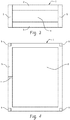
- FIG. 2 illustrates housing 1 incorporating frame 5 enclosing at least a portion of core layer 4 of the A-B-A structure.
- frame 5 can have a thickness that is less than or equal to the thickness of core layer 4.
- the frame can have a thickness greater than the thickness of core layer 4.
- frame 5 can have a thickness less than or equal to the thickness of housing 1 (e.g., first outer layer 2, second outer layer 3, and core layer 4).
- FIG. 4 is a top view of housing 1 including frame 5 and the A-B-A structure. As shown in FIG. 4 , frame 5 can extend outward in each direction beyond first outer layer 2. Frame 5 can include one or more attachment portions 6, which can be located anywhere on frame 5. In addition, frame 5 can include one or more reinforcement structures 7, such as ribs, and the like. Frame 5 can also include portions with rounded edges (e.g., corner radii) (e.g., see FIGs. 13 and 14 ).
- FIG. 5 illustrates a process for manufacturing for manufacturing a A-B-A structure or a housing.
- step 100 includes locating a first outer layer 2 on a first side of an injection mold.
- a second outer layer 3 is located on a second side of an injection mold, opposite the first side.
- the mold is closed.
- a first thermoplastic material is injected between the first outer layer 2 and the second outer layer 3 to form a core layer 4 in step 103.
- a housing can be formed wherein the first thermoplastic material can extend beyond first outer layer 2 and second outer layer 3 to form frame 5 extending from core layer 4.
- step 104 the mold is opened and A-B-A structure or housing 1 including first outer layer 2, core layer 4, second outer layer 4, and optionally frame 5 is removed from the mold.
- FIG. 6 illustrates a process for manufacturing a housing, e.g., for an electronic device.
- step 200 includes locating an A-B-A structure in an injection mold.
- the housing can include any of the housings described herein.
- the A-B-A structure of FIG. 1 can be utilized in step 200.
- the A-B-A structure can include solid core layer 4 formed from a first thermoplastic material, first outer layer 2 including a second thermoplastic material located on a first side of core layer 4, second outer layer 3 including the second thermoplastic material located on a second side of the core layer 4 opposite the first side.
- Step 201 includes closing the mold.
- a thermoplastic material can be injected around the A-B-A structure to form a frame 5 attached to the A-B-A structure.
- the frame and at least one layer of the A-B-A structure e.g., core layer 4 can be coupled through melt phase bonding.
- the mold is opened and the framed housing is removed.
- a set of multi-span flexural tests were conducted to assess the effectiveness of the A-B-A constructions.
- a thin wall sandwich composite consisting of single ply 0.25 mm Tencate CETEX TC 925 FST outer layers (7581 style E-glass fabric in a polycarbonate matrix, with a 50 vol% loading, and a thickness of 0.24 mm) and a 0.50 mm unreinforced LEXANTM 8B35 core was laminated in a vacuum assisted press. Total laminate thickness was 1.00 mm and core/outer layer thickness ratio was 0.50. Nominal flexural dimensions were 25 mm x 100 mm. Samples were tested at four spans to eliminate geometric and shear related effects. Samples were also taken in three orientations to test for anisotropy.
- flexural samples were machined in directions that correspond to the "warp”, “weft” and “off' orientations of the outer layers.
- TC 925 FST uses a 7581 E-glass fabric. This is an 8 harness satin with a relatively “balanced' structure.
- Directional samples were produced to aid in the understanding of laminate anisotropy.
- An identical set of samples and tests were run on as-produced 1.00 mm CETEX TC 925 FST laminates.
- These 4-layer through-thickness controls represent the maximum achievable properties with this combination of resin (PC) and reinforcement (7581 style E-glass fabric). Results are shown in Table 1.
- a layer is CETEX having a thickness of 0.24 mm.
- 2 Through thickness is a CETEX multilayer sheet.
- Side 1 and Side 2 refer to the same sample being tested on both sides (tested, flipped, and retested). The difference in the results is due to any warpage/bow in the construction.
- FIGS. 7-9 compare the performance of polycarbonate based sandwich constructions using 20% short carbon filled polycarbonate as a baseline.
- Various A-B-A sandwich constructions are compared on the basis of weight, stiffness and current costs.
- the "target” in this instance is a hypothetical 20% carbon reinforced PC based notebook housing with a wall thickness of 0.059 inches (in) (1.5 mm), weight of 0.267 pounds (lb) (121 grams (g)) and projected area of 95.4 square inches (in 2 ) (615.8 square centimeters (cm 2 )).
- Flexural stiffness for the housing is 27.6 lb-in 2 (0.19 megaPascal (MPa)) All systems are compared at a flexural stiffness equivalent to this value.
- TC 925 refers to polycarbonate based 66 wt.% E-glass reinforced (7581 fabric) laminate having a thickness of 0.0094 in (0.24 mm) (e.g., Tencate Cetex TC 925 FST-7581 laminate).
- 121 refers to unreinforced polycarbonate (e.g., SABIC LEXANTM 121).
- 3412HF refers to a 20% short glass reinforced polycarbonate injection molding compound (e.g., SABIC LEXANTM 3412HF).
- DC0049XF refers to a 20% short carbon reinforced polycarbonate injection molding compound (e.g., SABIC ThermocompTM DC0049XF).
- the A-B-A constructions include a single layer of TC925 laminate (A-layer) with a B-layers of 122, 3412HF, or DC0049XF.
- the A-B-A constructions offer significant benefit in thickness and weight over the injection molded polycarbonate at the same flexural stiffness of 27.6 lb-in 2 (0.19 MPa). As shown in FIG. 9 , A-B-A constructions offer significant savings in terms of cost when compared to the TC 925 through thickness composite.
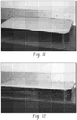
- FIGS. 10-12 illustrate examples of thin-wall composite housings that have been produced by overmolding a frame onto a A-B-A construction.
- the A-B-A construction of FIGS. 10-12 include E-glass reinforced polycarbonate cores, and the injection molded frame materials are unreinforced polycarbonate ( FIG. 10 ), 10 wt% short glass reinforced polycarbonate ( FIG. 11 ), and 20% short carbon fiber reinforced polycarbonate ( FIG. 12 ) respectively.
- the difference in the coefficient of thermal expansion between the frame material and the laminate material results in significant bowing.
- the frame materials of FIGS. 11 and 12 have coefficients of thermal expansion that closely match the coefficient of thermal expansion of the A-B-A structure.
- the examples of FIGS. 11 and 12 illustrate that flat samples can be produced when the coefficients of thermal expansion for the frame material and the laminate material are closely matched.
- FIG.s 13 and 14 are photos of a tablet sized housing, e.g., for an electronic device, manufactured according to the method of FIG. 6 .
- This housing demonstrates principles disclosed herein.
- the overmolded laminate can be a polycarbonate based construction with 66 wt. % E-glass outer layers and an unreinforced polycarbonate core.
- Total A-B-A structure thickness (t) is 1.00 mm with a core ("B") layer thickness (t c ) of 0.50 mm, hence t c /t is 0.50.
- the overmolding resin is also a polycarbonate based system. It is an E-glass short fiber filled compound with a coefficient of thermal expansion chosen to match the overall thermoelastic characteristics of the polycarbonate A-B-A structure. The result is a well-bonded and dimensionally stable part.
- A-B-A constructions that utilize unreinforced cores as described in FIG. 1 are especially well suited for overmolding operations.
- Use of an unreinforced core lowers the effective CTE of the A-B-A laminate and allows the use of overmolding resins with lower filler levels. This is desirable because high filler loading levels in injection resins result in high viscosities and filling pressures.
- the extremely high filler levels that are required to match CTE and laminate shrinkage for through-thickness constructions exhibit lower impact performance. High filling pressures and low impact performance are undesirable characteristics for an overmolded frame.
- peel strength is determined in accordance with ASTM D1781 (1994): standard test method for climbing drum peel for adhesives. Unless specifically specified otherwise, the test standards set forth herein are the most recent version as of July 9, 2014.
Landscapes
- Engineering & Computer Science (AREA)
- Theoretical Computer Science (AREA)
- Computer Hardware Design (AREA)
- Mechanical Engineering (AREA)
- Manufacturing & Machinery (AREA)
- Human Computer Interaction (AREA)
- Physics & Mathematics (AREA)
- General Engineering & Computer Science (AREA)
- General Physics & Mathematics (AREA)
- Textile Engineering (AREA)
- Laminated Bodies (AREA)
- Casings For Electric Apparatus (AREA)
- Injection Moulding Of Plastics Or The Like (AREA)
Description
- Housings for electronic devices, such as notebook, notepad and smartphone enclosures, can benefit from certain mechanical properties. For example, industry trends benefit from housings that are thin, light-weight, and can be manufactured at low cost. In an attempt to meet industry demand, a variety of materials are used for electronic device housings. However, efforts to make thinner and lighter housings using different materials and production methods have resulted in undesirable performance and cost tradeoffs.
-
U.S. Patent No. 8,372,495 discloses a housing for an electronic device or other object formed in a layered configuration. The layer or sandwich construction imparts strength and rigidity while decreasing the overall weight to the housing. The case/housing may have a first layer and a second layer formed from a first material. The case may also include a core formed from a second material. Where the first layer may be bonded to a top surface of the core and the second layer may be bonded to a bottom surface of the core.US 2010/040902 A1 discloses light-weight composite materials, which can be processed to form an outer covering layer, comprising a metallic layer and a polymeric layer, the polymeric layer containing a filled thermoplastic polymer which includes a thermoplastic polymer and a metallic fiber.JP 2014127518 A -
WO2013070447 discloses a photovoltaic module, comprising a transparent superstrate; a backsheet, wherein the backsheet comprises a core layer comprising a core composition formed from a first polycarbonate comprising dimethyl bisphenol cyclohexane carbonate repeat units and bisphenol-A, wherein the first polycarbonate has the structure wherein the dimethyl bisphenol cyclohexane carbonate repeat units are present in an amount of 10 wt.% to 50 wt.%, based on the total repeat units in the core composition; and a second polycarbonate selected from the group consisting of a bisphenol-A polycarbonate homopolymer, a polyphthalate carbonate copolymer, polycarbonate copolymer comprising 2-phenyl-3,3-bis(4-hydroxyphenyl) phthalimidine carbonate and bisphenol-A carbonate repeat units, a polycarbonate copolymer comprising bisphenol-A carbonate and tetrabromobisphenol A carbonate repeat units, and combinations comprising at least one of the foregoing; and a photovoltaic cell between the superstrate and the backsheet. - Disclosed herein are A-B-A structures, housings comprising the structures, and methods of making the same, in accordance with claims 1, 13, 12 and 14, respectively.
- According to the present invention, the A-B-A structure, comprising:a core layer comprising a first thermoplastic material having a first density (Y), wherein the core layer has a core thickness and wherein the core layer comprisea through plane thermal conductivity of greater than equal to 0.1 W/mK,wherein thermal conductivity is determined in accordance with ASTM E1461 using laser flash method, wherein test specimens were cut into 10x10x3 mm square samples from an injection molded 80x10x3 mm IZOD bar, anda core layer density (X) that is X > 0.8Y;a first outer layer comprising a second thermoplastic material located on a first side of the core layer; anda second outer layer comprising the second thermoplastic material located on a second side of the core layer opposite the first side;wherein the core thickness is 30 % to 75% of a total thickness, or 40 % to 60% of a total thickness, or 45 % to 55% of a total thickness, or 55 % to 70 % of a total thickness of the A-B-A structure, and wherein the core layer comprises 0 vol% to 35 vol% of a reinforcing material and 100 vol % to 65 vol% of the first thermoplastic material, based upon the total volume of the core layer.
- The above described and other features are exemplified by the following figures and detailed description.
- Refer now to the figures, which are exemplary embodiments, and wherein the like elements are numbered alike.
-
FIG. 1 is a cross sectional side view of an embodiment of an A-B-A structure. -
FIG. 2 is a cross sectional side view of an embodiment of an A-B-A structure with a frame that can be used as a housing. -
FIG. 3 is a cross sectional side view of an embodiment of an A-B-A structure with a frame that can be used as a housing. -
FIG. 4 is a top view of an embodiment of an embodiment of an A-B-A structure with a frame that can be used as a housing. -
FIG. 5 is a flow diagram depicting a process for forming the A-B-A structure ofFIGS. 1-4 . -
FIG. 6 is a flow diagram depicting a process for forming the A-B-A structure ofFIGS. 1-4 . -
FIG. 7 is a chart illustrating the part thickness of a simulated part at a target stiffness. -
FIG. 8 is a chart illustrating the part weight of a simulated part at a target stiffness. -
FIG. 9 is a chart illustrating the estimated cost of a simulated part at a target stiffness. -
FIG. 10 is a photo of an embodiment of an A-B-A structure with a frame that can be used as a housing manufactured according to the method ofFIG. 6 . -
FIG. 11 is a photo of an embodiment of an A-B-A structure with a frame that can be used as a housing manufactured according to the method ofFIG. 6 . -
FIG. 12 is a photo of an embodiment of an A-B-A structure with a frame that can be used as a housing manufactured according to the method ofFIG. 6 . -
FIG. 13 is a photo of a top view of an embodiment of an A-B-A structure with a frame that can be used as a housing manufactured according to the method ofFIG. 6 . -
FIG. 14 is a photo of a bottom view of the tablet sized A-B-A structure ofFIG. 13 . -
FIG. 15 is a photo of a center loaded plate fixture for testing the constructions of Table 1. -
FIG. 16 is a prospective view of an embodiment of a patterned fabric for use in the "A" layer of an A-B-A structure. -
FIG. 17 is a cross sectional side view of an embodiment of an A-B-A structure with a frame that can be used as a housing such as for an electronic device. - Disclosed herein are A-B-A structures, housings (e.g., for electronic devices), and methods of making the same.
-
WO2013070447 does not disclose or suggest the use of a sandwich construction for an electronic device housing. Thus,WO2013070447 does not identify or solve the problem of producing a light-weight, thin enclosure that can meet the mechanical requirements of a housing for an electronic device. -
U.S. Patent No. 8,372,495 discloses the use of a sandwich construction including a unidirectional carbon fiber reinforced polymer (CFRP) skin and a lower density core. CFRP materials generally do not resist bending or stresses applied in a direction transverse to the length of the carbon fibers. In order to compensate for low transverse stiffness and strength, sandwich skins produced from unidirectional CFRP must be layered to produce quasi-isotropic constructions. Layered CFRP skins add to the cost, complexity and thickness of the sandwich construction. In addition,U.S. Patent No. 8,373,495 describes low density cores made from foam or honeycomb structures. The thermal conductivity and diffusivity of these cores are much lower than a solid structure because a large portion of core volume consists of air. Foams and honeycomb structures have a thermal conductivity that can be less than 0.02 watts per meter kelvin (W/mK). Lower wall conductivity leads to higher internal temperatures, which is an undesirable effect for an electronic device housing. In addition, skin adhesion for a foam or honeycomb core is limited by the small area of contact between the skin and honeycomb. Sandwich constructions that are produced using low density foam or honeycomb cores have two other mechanical shortcomings. The first is related to lowered resistance to local penetration. For example, sharp local loads are resisted largely by the skins, and the core does not add significantly to penetration resistance. Second, sandwich constructions built with foam or honeycomb cores fail in compression when placed in flexure. The foam or honeycomb collapses underneath the skin before skin failure stresses are reached. Thus, failure strains for sandwich constructions with foam or honeycomb cores are lower than those that would occur if a solid core is used. - The featured A-B-A structures, housings, and methods of making described here provide light weight, thin-walled structures with high stiffness, high thermal conductivity, high flexural strength, and high peel strength. The A-B-A structure comprises a first thermoplastic material; a first outer layer comprising a second thermoplastic material located on a first side of the core layer and in physical contact therewith; a second outer layer comprising the second thermoplastic material located on a second side of the core layer opposite the first side and in physical contact with the core layer; wherein the core layer has a through plane thermal conductivity of greater than equal to 0.1 Watts per meter-Kelvin (W/mK); wherein the thickness of the core layer is 30% to 75% of the total thickness of the A-B-A structure. A housing according to the present invention comprises the A-B-A structure with a frame disposed around the structure, also optionally attached to the frame can be rib(s) and/or attachment features. If the housing is used for an electronic device, the housing can further comprise a backing, wherein the backing connects to the A-B-A structure via attachment features on the frame, and wherein electronic components can be located between the A-B-A structure and the backing.
- In particular, a housing for an electronic device comprises the A-B-A structure.
- This disclosure relates to an A-B-A structure, a housing comprising the A-B-A structure, and methods of making the same. In particular, disclosed herein is a thin-walled A-B-A structure including a thermoplastic composite construction. The composite construction preferably includes a sandwich construction including outer layers of reinforced material with an inner core of a thermoplastic material which may or may not be reinforced. The inner core can be a solid thermoplastic material or a substantially solid thermoplastic material. The present disclosure describes several less beneficial examples, to contrast with examples that are more beneficial.
- In one less beneficial approach, continuously reinforced thermoplastic "through thickness" composites (continuous reinforced layer(s) of one composition throughout) can be used to form thin-wall enclosures. Fabric reinforced systems offer benefits in mechanical properties (e.g., stiffness, strength, and in-plane isotropy) and formability. However, two factors have limited the use of these materials in enclosures. First, the cost of continuously reinforced systems is 4 to 5 times greater than the highest performance short carbon filled thermoplastics.
- In another less beneficial approach, full "through thickness" multilayer composite laminates (in other words, continuous reinforcement throughout; i.e., the same material in all layers) can be used in low volume, high end notebook enclosures. Typically, these materials can be thermoset materials similar to those used in the aerospace industry. However, the performance benefits of these stiff lightweight structures are outweighed by material costs and time consuming manufacturing methods. This combination of factors has limited their use in the broader enclosure market. Some manufacturers have adopted machined aluminum as a material solution. However, this approach is suffers the same drawbacks as the "through thickness" laminates.
- Glass, carbon and alternative short fiber reinforcements have been used to form enclosures, but the trend toward thinner wall thicknesses (e.g., less than 1.0 millimeter (mm)) creates challenging processing conditions. This is compounded by the fact that thinner walls require higher mechanical properties, which means higher reinforcement loadings to attain stiffer/high aspect ratio reinforcements. These specialty short fiber reinforced compounds have high melt viscosities which make them challenging to mold. In addition, high aspect ratio reinforcements result in higher than normal flow induced fiber orientation and (therefore) mechanical performance variability. Manufacturers of notebooks, notepads and smartphones are actively searching for materials that offer better mechanical properties, lower levels of in-plane anisotropy, and unobstructed package spaces.
- Attempts have been made using honeycomb or other low density foam structures between skin layers, wherein the skin layers form a total of less than or equal to 10% of the thickness of the total structure. However, these laminates exhibit low peel strength (typically less than 10 in-lb/in (1750 newton/meter) but occasionally up to 25 in-lb/in (4400 newton/meter) (depending on materials) because the skin layers are not in constant contact with the lightweight cores. For example, the gaps between the walls of the honeycomb structure are not in contact with the skin layer. In addition, these laminates have a lower thermal conductivity and diffusivity than a solid structure of the same material. As such, heat will be trapped by these structures, which is not favorable for a housing for an electronic device and can negatively impact the performance of the device. Finally, low density cores such as honeycomb and foam result in lowered resistance to local penetration. This is an especially important attribute for electrical enclosures where exposure of internal wiring and circuitry may pose a safety risk. In addition, structures built using low density cores rarely achieve their maximum theoretical mechanical capabilities because the cores will fail in compression prior to skin rupture. These attributes, combined with lower levels of thermal conductivity make low density cores less useful in sandwich structures for electrical enclosures.
- Accordingly, a need exists for housings for electronic devices that are thin, low weight (as compared to a through thickness structure having the same stiffness and using the same materials, has a weight that is greater than or equal to 12%, e.g., greater than or equal to 15% lighter than a through thickness structure), cost effective, and possess suitable thermal conductivity and mechanical properties.
- More beneficial approaches described here include thin-walled housings for electronic devices and methods of making the same. It is believed that the favorable results obtained herein (e.g., a thin, low weight, high strength A-B-A structure), can be achieved through a sandwich construction including a thermoplastic core (e.g., a solid thermoplastic core) between thermoplastic composite outer layers. Specific parametric maxima and minima are disclosed to highlight certain examples with desirable performance.
- The A-B-A structure disclosed herein are A-B-A sandwich constructions in which an "A" material forms a first outer layer and a second outer layer located on opposite sides of a solid core layer formed from a "B" material. The solid core can include a first thermoplastic material and the first outer layer and second outer layer can include a second thermoplastic material. The first and second thermoplastic materials are compatible (and hence adhere to each other). These materials can be the same type of thermoplastic material, with different viscosities (e.g., having different molecular weights and/or having different reinforcement loadings). The A-B-A structure can utilize highly filled (e.g., greater than or equal to 35 volume percent (vol.%), e.g., 35 vol.% to 70 vol.% reinforcing material, based upon the total volume of the outer layer) outer layers ("A"). The outer layers can be continuously reinforced, e.g., can comprise a fiber that was produced in a continuous form.
- The overall thickness of the A-B-A structure can be less than or equal to 1.6 millimeters (mm), for example, less than or equal to 1.5 mm, or less than or equal to 1.25 mm, or less than or equal to 1.0 mm. The overall thickness of the A-B-A structure can be 0.5 mm to 1.5 mm, for example 0.5 mm to 1.25 mm, or 0.75 mm to 1.1 mm. The core layer has a core thickness (tc) of 30 % to 75% of the total thickness of the A-B-A structure. The core layer can include 40 % to 60% of the total thickness of the A-B-A structure. The core layer can include 45 % to 55% of the total thickness of the A-B-A structure. The core layer can include 55 % to 70 % of the total thickness of the A-B-A structure. The flexural modulus of the A-B-A structure can be greater than or equal to 2,000,000 pounds per square inch (psi) (13.8 GigaPascals (GPa)), for example, greater than or equal to 5,000,000 psi (34.5GPa).
- The housing can comprise a frame that can be located about a periphery of at least a portion of the A-B-A structure. The frame can include a material that is compatible with the A-B-A structure, and desirably, a material that minimally changes the shape of the A-B-A structure before (initial shape) and after (final shape) the frame is attached (e.g., the change from initial shape to final shape is a bowing of less than or equal to 2 mm, specifically less than or equal to 1 mm, or less than or equal to 0.2 mm, or no change). For example, if the A-B-A structure is flat (no curvature), then the change from flat (e.g. the separation from a flat surface) is less than or equal to 2 mm, specifically less than or equal to 1 mm, or less than or equal to 0.2 mm, or no separation (measurable without a microscope). Desirably, there is no change in the shape of the A-B-A structure (e.g. a deflection from initial shape to final shape of 0%). For example, if a flat final article is desired, the frame can include a material that has a coefficient of thermal expansion that differs from the coefficient of thermal expansion of the A-B-A laminate such that, before the frame is attached and after the frame has been molded onto the A-B-A laminate, the A-B-A laminate remains flat. For example, the frame can comprise a thermoplastic material (e.g., the first thermoplastic material or the second thermoplastic material) and reinforcement (e.g., filler or reinforcing material). Possible reinforcements include fibers (e.g., short fibers (such as fibers having a length of less than or equal to 10 mm). The reinforcement material can be any of the materials used for the filler or reinforcing material in the A-B-A structure as described below. For example the reinforcement can comprise high stiffness inorganic fibers (e.g., glass, carbon, quartz, boron, and combinations comprising at least one of the foregoing), wherein high stiffness refers to a tensile modulus of greater than or equal to 35 GPa, for example, a tensile modulus of greater than or equal to 45 GPa.
- Optionally, the frame can be a metallic frame, such as magnesium or aluminum. For example, the frame can be a tube of metallic material that is perforated to encourage mechanical adhesion to the A-B-A structure (e.g., to the first and/or second material).
- The frame can have a thickness greater than the thickness of the A-B-A laminate (e.g., as measured from the outer surface of one A layer to the outer surface of the other A layer). The frame can have a thickness less than or equal to the thickness of the A-B-A laminate. The frame can allow for the inclusion of attachment features, ribs, and corner radii.
- The core layer can have a thermal conductivity that enables the dissipation of heat from the electronic device. For example, the first thermoplastic material can have a through plane thermal conductivity of greater than or equal to 0.1 W/mK.
- Thermal conductivity is determined in accordance with ASTM E1461 using laser flash method with a Nanoflash LFA 447 xenon flash apparatus available from Netzsch. For the through plane thermal conductivity, test specimens were cut into 10x10x3 mm square samples from an injection molded 80x10x3 mm IZOD bar. The thermal conductivity (k(T)) is calculated in units of W/mK. The thermal diffusivity (α(T)) is measured in units of square centimeters per second (cm2/s), and can be determined by measurement of time needed for the rear face of a thin-disc specimen to achieve maximum temperature rise after a short energy pulse input on the front face. The pulse is emitted by the xenon flash lamp with the fixed parameters setting on power, filter, pulse width, pre-amp and main amp. The thermal diffusivity can be calculated as shown in formula (1), below


- The core layer can be solid, wherein the core layer can include a density that is not reduced by air pockets or structural design, such as a honeycomb structure. For example, the core layer can have a density (X) that is greater than or equal to the density (Y) of the first thermoplastic material. In another embodiment, the core layer can be a structural foam, wherein the core layer can include a density (X) that is X≥0.8Y. In the present invention, the core layer density (X) should be at least equal to 0.8Y.
- The first thermoplastic material, the second thermoplastic material, or both first thermoplastic material and the second thermoplastic material can include polycarbonate (PC), acrylonitrile butadiene styrene (ABS), acrylic rubber, ethylene-vinyl acetate (EVA), ethylene vinyl alcohol (EVOH), liquid crystal polymer (LCP), methacrylate styrene butadiene (MBS), polyacetal (POM or acetal), polyacrylate and polymethacrylate (also known collectively as acrylics), polyacrylonitrile (PAN), polyamide (PA, also known as nylon), polyamide-imide (PAI), polyaryletherketone (PAEK), polybutadiene (PBD), polybutylene (PB), polyesters such as polybutylene terephthalate (PBT), polycaprolactone (PCL), polyethylene terephthalate (PET), polycyclohexylene dimethylene terephthalate (PCT), and polyhydroxyalkanoates (PHAs), polyketone (PK), polyolefins such as polyethylene (PE) and polypropylene (PP), polyetheretherketone (PEEK), polyetherketoneketone (PEKK), polyetherimide (PEI), polyethersulfone (PES), polysulfone, polyimide (PI), polylactic acid (PLA), polymethylpentene (PMP), polyphenylene oxide (PPO), polyphenylene sulfide (PPS), polyphthalamide (PPA), polypropylene (PP), polystyrene (PS), polysulfone (PSU), polyphenylsulfone, polytrimethylene terephthalate (PTT), polyurethane (PU), styreneacrylonitrile (SAN), or any combination comprising at least one of the foregoing. For example, the first thermoplastic material can comprise polycarbonate, polyetherimide, polyphenylene oxide, and nylon, and combinations comprising at least one of the foregoing. Polycarbonate blends with ABS, SAN, PBT, PET, PCT, PEI, PTFE, or combinations thereof are of particular note to attain the balance of the desirable properties such as melt flow, impact and chemical resistance. The first thermoplastic material can include
SABIC LEXAN™ 121, SABIC Thermocomp DC0049XF, and similar materials, commercially available from SABIC Innovative Plastics. - The core layer ("B" layer) can be neat (no reinforcement). Alternatively, the core layer can include a reinforcing material. The reinforcing material can include fibers, (continuous, chopped, woven, and the like). The core layer includes 0 to 35 vol% reinforcing material and 100 to 65 vol.% first thermoplastic material. The core layer can include about 10 vol% to 35 vol% reinforcing material (e.g., glass fibers) and 90 to 65 vol% first thermoplastic material. The core layer can include about 5 vol% to 30 vol% reinforcing material (e.g., carbon fibers) and 95 to 70 vol% first thermoplastic material. The core layer can include about 5 vol% to 25 vol% reinforcing material (e.g., carbon fibers) and 95 to 75 vol% first thermoplastic material. The core layer can comprise short fibers (e.g. short glass fibers).
- The "A" layer can include fabric based composites (e.g., reinforcing material in the form of a fabric in a matrix of the second thermoplastic material). For example, satin harness style weaves and low basis weight "spread tow" fabrics can be used. As used herein low basis weight is less than 50 grams per square meter (gsm). The fabric based composite can have a basis weight of 50 to 500 gsm. The fabric based composite can have a basis weight of 100 to 400 gsm. The fabric based composite can have a basis weight of 200 to 400 gsm.
- The second thermoplastic material can include co-mingled, co-woven and stretch broken yarn fabrics. A variety of technical weaves can be used including, but not limited to, plain, twill, basket, leno and satin weaves. The fabric can be a patterned fiber layer, e.g., a patterned fabric within a second material. The pattern of the material can be designed to reduce the amount of fibers (and hence weight), while maintaining strength. Therefore, the "A" layer can be custom designed for the particular application wherein the fibers are oriented to enhance structural integrity in areas that are higher stress during use. Some examples of patterned fabrics include polygonal cells (e.g., hexagonal cells (see
FIG. 16 ), triangular cells, pentagonal cells), rounded cells, or a combination comprising at least one of the foregoing, e.g., the patterned fabric can be hexagonal cells.. In some embodiments, the patterned fabric can be a perforated material. As used herein, a patterned fabric is a tailored pattern that locates fabric where needed in order to attain the strength and stiffness for the application of the article. In some embodiments patterned fabric is not a uniformly repeated pattern. The patterned fabric can be an open weave (e.g., a woven fabric with spaces between adjacent strands). The patterned fabric can have a non-uniform density across the fabric, such as illustrated inFIG. 16 , wherein some areas comprise fabric and others are free of fabric.FIG. 17 illustrates an A-B-A structure wherein the outer layers "A" comprise a patterned fabric. - The reinforcing material can comprise aramid, carbon, basalt, glass, plastic (e.g., thermoplastic polymer, thermoset polymer), quartz, boron, cellulose, or natural fibers, as well as combinations comprising at least one of the foregoing, such as high stiffness inorganic fibers (e.g., glass, carbon, quartz, boron, and combinations comprising at least one of the foregoing). High stiffness refers to a tensile modulus of greater than or equal to 35 GPa. For example, the fibers can be formed of liquid crystal polymer, high tenacity polymer (e.g., polypropylene, polyethylene, poly(hexano-6-lactam), poly[imino(1,6-dioxohexamethylene) imnohexamethylene]), as well as combinations comprising at least one of the foregoing. An exemplary fiber filled resin is LEXAN™ resin, commercially available from SABIC Innovative Plastics. Another exemplary fibrous material can include fiber reinforced thermoplastics such as ULTEM™ resins, commercially available from SABIC Innovative Plastics). For example, a variety of reinforcement fibers may be used for the outer layers. For example, E-glass, S-glass and various carbon based systems, and combinations comprising at least one of the foregoing, may be employed, e.g., a glass (e.g. E-glass) - carbon hybrid fabric. The outer layer can have a different reinforcing material than the core layer. Certain enclosure applications may need radio frequency transparency. Thus, glass reinforcement can be used in the outer layer in these applications. An exemplary reinforcing material (e.g., for the outer layers) is Tencate CETEX TC925 FST or Tencate CETEX TC1000 commercially available from Ten Cate Advanced Composites.
- The second thermoplastic material can be any of the materials listed above for the first thermoplastic material. For example, the second thermoplastic material can include polypropylene (PP), polyamide (PA), polycarbonate (PC), polyphenylene sulfide (PPS), polyetherimide (PEI), polyetheretherketone (PEEK), and the like. The outer layers can include reinforcing material loading levels of greater than or equal to 35 volume percent (vol.%), e.g., 35 vol.% to 70 vol.% reinforcing material, or 40 vol.% to 60 vol.% reinforcing material, based upon a total weight of the outer layer.
- The second thermoplastic material can be chemically compatible with the first thermoplastic material to promote adhesion between the outer layers and the core layer. Thus, the use of an adhesive between the core layer and the outer layer can be minimized or completely eliminated. For example, the first thermoplastic material and the second thermoplastic material can have the same base polymer (e.g., polycarbonates with different amounts and/or types of reinforcing material). The viscosity of the first thermoplastic material can be different from the viscosity of the second thermoplastic material. For example, the first thermoplastic material can have a higher viscosity than the second thermoplastic material. Thus, the core layer made from the higher viscosity first thermoplastic material can resist "squeezing out" in preforming operations. The difference in melt flow rate for the second thermoplastic material versus the first thermoplastic material can be such that a melt flow rate of the second thermoplastic material ≥ 2 x melt flow rate of the first thermoplastic material, e.g., melt flow rate of the second thermoplastic material ≥ 3 x melt flow rate of the first thermoplastic material. For example for polycarbonate based materials, second thermoplastic material can have a melt flow rate of greater than or equal to 25 grams per 10 minutes (g/10 min), or greater than or equal to 45 g/10 min, or greater than or equal to 50 g/10 min. The first thermoplastic material can have a melt flow rate of less than or equal to 10 g/10 min. Melt flow rate is determined in accordance with ASTM D1238, using a temperature and weight appropriate for the material of the layers as is specified in the standard.
- The first and second thermoplastic materials can include coefficients of thermal expansions that are "matched." As used herein, "matched" means that a flat A-B-A structure can be formed (e.g., the core layer can be adhered to the outer layers, and once cooled, the structure is not warped. For example, the A-B-A structure can have a bowing that is less than or equal to 2 mm from flat, e.g., less than or equal to 1 mm from flat, or less than or equal to 2 mm from flat, such as no measureable distance from flat (without a microscope). As used herein, "matched" means having a value that differs by less than or equal to 20%. The coefficients of thermal expansion for the first thermoplastic material and the second thermoplastic material can differ by less than or equal to 10%. The coefficients of thermal expansion for the first thermoplastic material and the second thermoplastic material can differ by less than or equal to 5%.
- The housing and frame can be manufactured in a single step through injection molding. For example, the "A" or outer layers (e.g., preformed pattered fabric impregnated outer layers or reinforced outer layers) can be prepositioned on opposite sides of an injection mold. Optionally, static charge, mechanical holders (e.g., pins), vacuum, or other methods, may be used to hold the precut layers in-place. In this embodiment, the layer that is placed on the movable mold half can be pre-pierced for hot drops and ribs and molded-in features. The mold is closed and the "B" or core layer is injected between the "A" or outer layers. In this manner, a center A-B-A region is formed. The frame, consisting entirely of the "B" layer can be formed simultaneously and surrounds the central A-B-A.
- In the alternative, a premolded frame comprising a compatible resin is placed in the mold along with the "A" or outer layers. A small gap (1 - 10 mm) is left between the frame and the "A" layer. The mold is closed and the filling process proceeds as previously described. The "B" layer is used to bond the premolded frame to the central A-B-A laminate. Thus, an unreinforced (e.g., no filler) "B" layer can be used and the frame material can include another material that is compatible with the "B" layer.
- According to another method, an A-B-A sandwich housing is placed in an injection molding tool. The "A" material can be the second thermoplastic material and the "B" material can be the first thermoplastic material. A frame is then molded around the housing in an overmolding operation. The frame resin is selected to have physical and thermoelastic compatibility with the housing material. Optionally, the housing can be trimmed or otherwise treated prior to the overmolding process to enhance bonding of the frame to the core material. Treatments can include roughening, slotting, drilling, and the like.
- In the alternative, an A-B-A sandwich housing can be formed separately from a frame and then joined together, e.g., through welding such as ultrasonic welding.
- The outer layers can be preformed, e.g., as continuous reinforced outer layers or patterned fabric reinforced outer layers. These preformed outer layers can then be used in the processes described above.
- A more complete understanding of the components, processes, and apparatuses disclosed herein can be obtained by reference to the accompanying drawings. These figures (also referred to herein as "FIG.") are merely schematic representations based on convenience and the ease of demonstrating the present disclosure, and are, therefore, not intended to indicate relative size and dimensions of the devices or components thereof and/or to define or limit the scope of the exemplary embodiments. Although specific terms are used in the following description for the sake of clarity, these terms are intended to refer only to the particular structure of the embodiments selected for illustration in the drawings, and are not intended to define or limit the scope of the disclosure. In the drawings and the following description below, it is to be understood that like numeric designations refer to components of like function.
-
FIG. 1 illustrates the A-B-A sandwich construction. As shown inFIG. 1 , the A-B-A structure includes firstouter layer 2 located on a first surface ofcore layer 4. Secondouter layer 3 is located on a second surface ofcore layer 4 opposite the first surface.Core layer 4 can include a first thermoplastic material and a core thickness (tc). Firstouter layer 2 and secondouter layer 3 can include a second thermoplastic material. A-B-A structure includes a total thickness t, which includes core thickness (tc), and the thickness of first outer layer and second outer layer. -
FIG. 2 illustrates housing 1 incorporatingframe 5 enclosing at least a portion ofcore layer 4 of the A-B-A structure. As shown inFIG. 2 ,frame 5 can have a thickness that is less than or equal to the thickness ofcore layer 4. As shown inFIG. 3 , the frame can have a thickness greater than the thickness ofcore layer 4. For example,frame 5 can have a thickness less than or equal to the thickness of housing 1 (e.g., firstouter layer 2, secondouter layer 3, and core layer 4). -
FIG. 4 is a top view of housing 1 includingframe 5 and the A-B-A structure. As shown inFIG. 4 ,frame 5 can extend outward in each direction beyond firstouter layer 2.Frame 5 can include one ormore attachment portions 6, which can be located anywhere onframe 5. In addition,frame 5 can include one ormore reinforcement structures 7, such as ribs, and the like.Frame 5 can also include portions with rounded edges (e.g., corner radii) (e.g., seeFIGs. 13 and 14 ). -
FIG. 5 illustrates a process for manufacturing for manufacturing a A-B-A structure or a housing. As illustrated inFIG. 5 ,step 100 includes locating a firstouter layer 2 on a first side of an injection mold. Instep 101, a secondouter layer 3 is located on a second side of an injection mold, opposite the first side. Instep 102, the mold is closed. A first thermoplastic material is injected between the firstouter layer 2 and the secondouter layer 3 to form acore layer 4 instep 103. Optionally, a housing can be formed wherein the first thermoplastic material can extend beyond firstouter layer 2 and secondouter layer 3 to formframe 5 extending fromcore layer 4. Instep 104, the mold is opened and A-B-A structure or housing 1 including firstouter layer 2,core layer 4, secondouter layer 4, andoptionally frame 5 is removed from the mold. -
FIG. 6 illustrates a process for manufacturing a housing, e.g., for an electronic device. As illustrated inFIG. 6 ,step 200 includes locating an A-B-A structure in an injection mold. The housing can include any of the housings described herein. In particular, the A-B-A structure ofFIG. 1 can be utilized instep 200. For example, the A-B-A structure can includesolid core layer 4 formed from a first thermoplastic material, firstouter layer 2 including a second thermoplastic material located on a first side ofcore layer 4, secondouter layer 3 including the second thermoplastic material located on a second side of thecore layer 4 opposite the first side. Step 201 includes closing the mold. Instep 202, a thermoplastic material can be injected around the A-B-A structure to form aframe 5 attached to the A-B-A structure. The frame and at least one layer of the A-B-A structure (e.g., core layer 4) can be coupled through melt phase bonding. Instep 203, the mold is opened and the framed housing is removed. - A set of multi-span flexural tests were conducted to assess the effectiveness of the A-B-A constructions. A thin wall sandwich composite consisting of single ply 0.25 mm Tencate CETEX TC 925 FST outer layers (7581 style E-glass fabric in a polycarbonate matrix, with a 50 vol% loading, and a thickness of 0.24 mm) and a 0.50 mm unreinforced LEXAN™ 8B35 core was laminated in a vacuum assisted press. Total laminate thickness was 1.00 mm and core/outer layer thickness ratio was 0.50. Nominal flexural dimensions were 25 mm x 100 mm. Samples were tested at four spans to eliminate geometric and shear related effects. Samples were also taken in three orientations to test for anisotropy. Specifically, flexural samples were machined in directions that correspond to the "warp", "weft" and "off' orientations of the outer layers. TC 925 FST uses a 7581 E-glass fabric. This is an 8 harness satin with a relatively "balanced' structure. Directional samples were produced to aid in the understanding of laminate anisotropy. An identical set of samples and tests were run on as-produced 1.00 mm CETEX TC 925 FST laminates. These 4-layer through-thickness controls represent the maximum achievable properties with this combination of resin (PC) and reinforcement (7581 style E-glass fabric). Results are shown in Table 1.
Table 1. Flexural Modulus Comparison, 1.00 mm PC/E-glass (66 Wt.%) Laminates Multi-span 3 Pt. Flexural Modulii [GPa] 3 Pt. Flexural Span [mm] 40 50 60 70 Average [GPa] % of Thru PC/E-glass ABA Warp 17.49 20.12 20.42 20.42 19.61 75.4% Weft 15.20 15.83 16.65 16.65 16.08 85.7% Off 11.36 11.88 11.67 11.67 11.65 83.2% PC/E-glass thru Warp 23.24 26.17 27.34 27.34 26.02 Weft 16.94 18.77 19.67 19.67 18.77 Off 13.49 14.01 14.23 14.23 13.99 Note: "A" layers are 0.25 mm Tencate CETEX TC 925 FST. "B" is 0.50 mm LEXAN 8B35 unreinforced PC film - Mathematical models proposed by Johnson and Sims1 predict flexural moduli that are 87% of through thickness values (assuming core/total thickness ratio = 0.50). Experimental results are close to these predictions. Data and theory support the concept that through thickness composites are not required to create stiff thin structures for use in electronic enclosures. The immediate benefits are lighter weight and lower costs. In this instance, 50% of the composite laminate is removed from the core with a modest 15% - 20% reduction in stiffness.
- Additional characterization work was done to verify the utility of A-B-A laminates in a laptop cover loading scenario. 220 mm x 335 mm laminates of the constructions described in Table 2 were tested in a center loaded plate fixture (
FIG. 15 ). A 100 Newton (N) load was applied to the center of the fully supported plate using a 13 mm circular loading nose. Laminates were tested with the long plate dimension (335 mm) aligned with the "warp" and "weft" directions of the CETEX TC 925 FST outer layers. In addition, a third laminate was taken in the "off' direction - a 45 degree offset from warp and weft. Samples were preloaded to 7 N to remove residual laminate "twist". Final deflections reflect movement after application of an additional 93 N. Similar procedures were used for A-cover qualification by laptop manufacturers. Results are shown in Table 2.Table 2: Centerpoint Plate Deflections, 100 N Load / 220 mm x 335 mm Panel Sample Description CETEX A-B-A1 CETEX Thru2 Al Overall Thickness 1.00 mm 1.25 mm 1.40 mm 1.00 mm, As-produced 1.00 mm, Off-core 1.50 mm, As-Produced 0.65 mm Warp, Side 1 6.34 6.24 6.22 5.44 5.40 4.26 4.20 Warp, Side 26.60 6.25 5.86 5.33 5.44 4.56 3.99 Weft, Side 1 6.78 6.39 5.96 5.75 5.43 4.56 Weft, Side 26.26 5.98 5.97 5.46 5.26 4.13 Off, Side 1 6.34 6.33 6.23 5.98 5.37 4.38 Off, Side 26.85 6.42 6.06 5.59 5.15 4.60 Average 3.53 6.27 6.05 5.59 5.34 4.42 Std. Dev. 0.25 0.16 0.15 0.24 0.11 0.19 Deflection Increase 16.8% 1A layer is CETEX having a thickness of 0.24 mm.
2Through thickness is a CETEX multilayer sheet.
3Aluminum sheet.
Side 1 andSide 2 refer to the same sample being tested on both sides (tested, flipped, and retested). The difference in the results is due to any warpage/bow in the construction. - Deflection of fully supported CETEX TC925 FST A-B-A constructions at 1.00 mm thickness (core/skin ratio of 0.50) is 17% larger than through thickness deflection. This is consistent with flexural results and further evidence of the benefits of A-B-A constructions for thinwall electronic enclosures. Fully supported plate bending is more complicated than simple flexural loading, because large in-plane tensile stresses are often present. The relatively "thick" outer layers that are specified in this document are better able to handle tensile stresses than "thin" skins that are used in traditional A-B-A constructions. This distinction is supported by the experimental results in Table 2. Data in this table also shows that substantial increases in core thickness (40%) rapidly meet with diminishing returns, e.g. lower deflections, at the wall thicknesses required for electronic enclosures. The core-thickness ratios that are described in the embodiments and claims of this document offer a good balance of stiffness and cost/weight reduction.
-
FIGS. 7-9 compare the performance of polycarbonate based sandwich constructions using 20% short carbon filled polycarbonate as a baseline. Various A-B-A sandwich constructions are compared on the basis of weight, stiffness and current costs. The "target" in this instance is a hypothetical 20% carbon reinforced PC based notebook housing with a wall thickness of 0.059 inches (in) (1.5 mm), weight of 0.267 pounds (lb) (121 grams (g)) and projected area of 95.4 square inches (in2) (615.8 square centimeters (cm2)). Flexural stiffness for the housing is 27.6 lb-in2 (0.19 megaPascal (MPa)) All systems are compared at a flexural stiffness equivalent to this value. As used inFIGS 7-9 , "TC 925" refers to polycarbonate based 66 wt.% E-glass reinforced (7581 fabric) laminate having a thickness of 0.0094 in (0.24 mm) (e.g., Tencate Cetex TC 925 FST-7581 laminate). "121" refers to unreinforced polycarbonate (e.g., SABIC LEXAN™ 121). "3412HF" refers to a 20% short glass reinforced polycarbonate injection molding compound (e.g., SABIC LEXAN™ 3412HF). "DC0049XF" refers to a 20% short carbon reinforced polycarbonate injection molding compound (e.g., SABIC Thermocomp™ DC0049XF). The A-B-A constructions include a single layer of TC925 laminate (A-layer) with a B-layers of 122, 3412HF, or DC0049XF. - As shown in
FIGS. 7 and 8 , the A-B-A constructions offer significant benefit in thickness and weight over the injection molded polycarbonate at the same flexural stiffness of 27.6 lb-in2 (0.19 MPa). As shown inFIG. 9 , A-B-A constructions offer significant savings in terms of cost when compared to the TC 925 through thickness composite. -
FIGS. 10-12 illustrate examples of thin-wall composite housings that have been produced by overmolding a frame onto a A-B-A construction. The A-B-A construction ofFIGS. 10-12 include E-glass reinforced polycarbonate cores, and the injection molded frame materials are unreinforced polycarbonate (FIG. 10 ), 10 wt% short glass reinforced polycarbonate (FIG. 11 ), and 20% short carbon fiber reinforced polycarbonate (FIG. 12 ) respectively. As shown inFIG. 10 , the difference in the coefficient of thermal expansion between the frame material and the laminate material results in significant bowing. In contrast, the frame materials ofFIGS. 11 and 12 have coefficients of thermal expansion that closely match the coefficient of thermal expansion of the A-B-A structure. Thus, the examples ofFIGS. 11 and 12 illustrate that flat samples can be produced when the coefficients of thermal expansion for the frame material and the laminate material are closely matched. -
FIG.s 13 and 14 are photos of a tablet sized housing, e.g., for an electronic device, manufactured according to the method ofFIG. 6 . This housing demonstrates principles disclosed herein. In this example, the overmolded laminate can be a polycarbonate based construction with 66 wt. % E-glass outer layers and an unreinforced polycarbonate core. Total A-B-A structure thickness (t) is 1.00 mm with a core ("B") layer thickness (tc) of 0.50 mm, hence tc /t is 0.50. The overmolding resin is also a polycarbonate based system. It is an E-glass short fiber filled compound with a coefficient of thermal expansion chosen to match the overall thermoelastic characteristics of the polycarbonate A-B-A structure. The result is a well-bonded and dimensionally stable part. - A-B-A constructions that utilize unreinforced cores as described in
FIG. 1 are especially well suited for overmolding operations. Use of an unreinforced core lowers the effective CTE of the A-B-A laminate and allows the use of overmolding resins with lower filler levels. This is desirable because high filler loading levels in injection resins result in high viscosities and filling pressures. In addition, the extremely high filler levels that are required to match CTE and laminate shrinkage for through-thickness constructions exhibit lower impact performance. High filling pressures and low impact performance are undesirable characteristics for an overmolded frame. - All ranges disclosed herein are inclusive of the endpoints, and the endpoints are independently combinable with each other (e.g., ranges of "up to 25 wt.%, or, more specifically, 5 wt.% to 20 wt.%", is inclusive of the endpoints and all intermediate values of the ranges of "5 wt.% to 25 wt.%," etc.). "Combination" is inclusive of blends, mixtures, alloys, reaction products, and the like. Furthermore, the terms "first," "second," and the like, herein do not denote any order, quantity, or importance, but rather are used to denote one element from another. The terms "a" and "an" and "the" herein do not denote a limitation of quantity, and are to be construed to cover both the singular and the plural, unless otherwise indicated herein or clearly contradicted by context. The suffix "(s)" as used herein is intended to include both the singular and the plural of the term that it modifies, thereby including one or more of that term (e.g., the film(s) includes one or more films). Reference throughout the specification to "one embodiment", "another embodiment", "an embodiment", and so forth, means that a particular element (e.g., feature, structure, and/or characteristic) described in connection with the embodiment is included in at least one embodiment described herein, and may or may not be present in other embodiments. In addition, it is to be understood that the described elements may be combined in any suitable manner in the various embodiments. As used herein, peel strength is determined in accordance with ASTM D1781 (1994): standard test method for climbing drum peel for adhesives. Unless specifically specified otherwise, the test standards set forth herein are the most recent version as of July 9, 2014.
Claims (14)
- An A-B-A structure, comprising:a core layer comprising a first thermoplastic material having a first density (Y), wherein the core layer has a core thickness and wherein the core layer comprise
a through plane thermal conductivity of greater than or equal to 0.1 W/mK,wherein thermal conductivity is determined in accordance with ASTM E1461 using laser flash method, wherein test specimens were cut into 10x10x3 mm square samples from an injection molded 80x10x3 mm IZOD bar, and
a core layer density (X) that is X ≥ 0.8Y;a first outer layer comprising a second thermoplastic material located on a first side of the core layer; anda second outer layer comprising the second thermoplastic material located on a second side of the core layer opposite the first side;wherein the core thickness is 30 % to 75% of a total thickness, or 40 % to 60% of a total thickness, or 45 % to 55% of a total thickness, or 55 % to 70 % of a total thickness of the A-B-A structure, andwherein the core layer comprises 0 vol% to 35 vol% of a reinforcing material and 100 vol% to 65 vol% of the first thermoplastic material, based upon the total volume of the core layer. - The structure of Claim 1, wherein the total thickness is 0.5 mm to 1.5 mm, preferably 0.5 mm to 1.25 mm, or 0.75 mm to 1.1 mm.
- The structure of any the preceding claims, wherein the first thermoplastic material and the second thermoplastic material comprises polypropylene, polyamide, polycarbonate, polyphenylene sulfide, polyetherimide, polyetheretherketone, and combinations comprising at least one of the foregoing; preferably, wherein the first thermoplastic material and the second thermoplastic material comprise polycarbonate.
- The structure of any of the preceding claims, wherein the core layer comprises 0 wt% reinforcing material.
- The structure of any of Claims 1-3, wherein the core layer comprises 5 vol% to 35 vol% reinforcing material, based upon the total volume of the core layer; preferably 5 vol% to 30 vol% reinforcing material; or preferably 5 vol% to 25 vol% reinforcing material; or 10 vol% to 35 vol% reinforcing material.
- The structure of any of Claims 1 - 5, wherein the first outer layer comprises greater than or equal to 35 vol.% reinforcing material based upon a total weight of the first outer layer, preferably 35 vol.% to 70 vol.% reinforcing material, or 40 vol.% to 60 vol.% reinforcing material; and wherein the second outer layer comprises greater than or equal to 35 vol.% reinforcing material based upon a total weight of the second outer layer, preferably 35 vol.% to 70 vol.% reinforcing material, or 40 vol.% to 60 vol.% reinforcing material.
- The structure of Claim 6, wherein the reinforcing material is a fabric;
preferably, wherein the reinforcing material is a patterned fabric and preferably, wherein the patterned fabric comprises at least one of
a tailored pattern with fabric where needed in order to attain the strength and stiffness for the application of the article;
a pattern that is not a uniformly repeated pattern;
an open weave fabric; and
a fabric having a non-uniform density across the fabric. - The structure of any of the preceding claims, wherein the core layer comprises a thermal conductivity of greater than or equal to 1 W/mK, wherein thermal conductivity is determined in accordance with ASTM E1461 using laser flash method, wherein test specimens were cut into 10x10x3 mm square samples from an injection molded 80x10x3 mm IZOD bar.
- The structure of any of the preceding claims, wherein the core layer density (X) is X ≥ Y.
- The structure of any of the preceding claims, wherein the first thermoplastic material has a first melt flow rate and the second thermoplastic material has a second melt flow rate, and wherein the second melt flow rate is greater than or equal to 2 x the first melt flow rate, wherein melt flow rate is determined in accordance with ASTM D1238, using a temperature and weight appropriate for the material of the layers as is specified in the standard; preferably, wherein the second melt flow rate is greater than or equal to 3 x the first melt flow rate, more preferably wherein the second melt flow rate is greater than or equal to 25 g/10 min; preferably, the second melt flow rate is greater than or equal to 45 g/10 min, or the second melt flow rate is greater than or equal to 50 g/10 min; and preferably, wherein the first melt flow rate is less than or equal to 10 g/10 min.
- The structure of any of the preceding claims, wherein when resting on a flat surface, the structure comprises separation from the flat surface of less than or equal to 2 mm, preferably less than or equal to 1 mm, or less than or equal to 0.2 mm, or no separation measurable without a microscope.
- A method for making the A-B-A structure of any of the preceding claims, comprising:locating the first outer layer on a first side of an injection mold;locating the second outer layer on a second side of an injection mold;closing the mold;forming the core layer by injecting the first thermoplastic material between the first outer layer and the second outer layer to form the A-B-A structure;opening the mold and removing the A-B-A structure.
- A method for forming a housing comprising the A-B-A structure of any of the preceding claims, comprising forming a frame around the A-B-A structure, wherein forming the frame comprises injection molding a thermoplastic material around the A-B-A structure; and opening the mold and removing the housing, preferably wherein the frame comprises a material that is compatible with the A-B-A structure, more preferably comprises the first thermoplastic material, such that the A-B-A structure is initially flat before the frame is formed around the A-B-A structure and has a final shape after the A-B-A structure is formed that when measured on a flat surface has a separation from the flat surface of less than or equal to 2 mm, preferably less than or equal to 1 mm, or less than or equal to 0.2 mm, or no separation that measurable without a microscope.
- An electronic device comprising:the housing of Claim 13 further comprising a backing; andelectronic components located between the A-B-A structure and the backing.
Applications Claiming Priority (2)
| Application Number | Priority Date | Filing Date | Title |
|---|---|---|---|
| US201462022333P | 2014-07-09 | 2014-07-09 | |
| PCT/IB2015/055211 WO2016005942A1 (en) | 2014-07-09 | 2015-07-09 | Thinwall composites for electronic enclosures and other devices |
Publications (2)
| Publication Number | Publication Date |
|---|---|
| EP3166787A1 EP3166787A1 (en) | 2017-05-17 |
| EP3166787B1 true EP3166787B1 (en) | 2020-06-03 |
Family
ID=54065392
Family Applications (1)
| Application Number | Title | Priority Date | Filing Date |
|---|---|---|---|
| EP15760240.0A Active EP3166787B1 (en) | 2014-07-09 | 2015-07-09 | Thinwall composites for electronic enclosures and other devices |
Country Status (6)
| Country | Link |
|---|---|
| US (2) | US10549512B2 (en) |
| EP (1) | EP3166787B1 (en) |
| JP (1) | JP2017527460A (en) |
| KR (1) | KR20170028946A (en) |
| CN (2) | CN109927377A (en) |
| WO (1) | WO2016005942A1 (en) |
Families Citing this family (20)
| Publication number | Priority date | Publication date | Assignee | Title |
|---|---|---|---|---|
| GB201411511D0 (en) * | 2014-06-27 | 2014-08-13 | Victrex Mfg Ltd | Polymeric materials |
| US20170248992A1 (en) * | 2016-02-25 | 2017-08-31 | Microsoft Technology Licensing, Llc | Systems and apparatus for housing electronic components and methods thereof |
| US20190070839A1 (en) * | 2016-04-06 | 2019-03-07 | Sabic Global Technologies B.V. | Filler-reinforced solid resin multilayered structure |
| JP6059841B1 (en) * | 2016-05-16 | 2017-01-11 | 則之 加納 | Molding method of resin structure integrated with two-dimensional steel fabric |
| JP7114621B2 (en) | 2017-03-15 | 2022-08-08 | サムソナイト アイピー ホールディングス エス.エー.アール.エル. | Biaxially oriented thermoplastic polymer laminate film for luggage articles and method of making same |
| CN107379394A (en) * | 2017-04-07 | 2017-11-24 | 通达(厦门)精密橡塑有限公司 | A kind of dijection injection molding forming method of ultrathin screen cloth+plastic cement |
| CN107283977B (en) * | 2017-07-12 | 2019-03-26 | 合肥东恒锐电子科技有限公司 | A kind of composite material for computer casing |
| EP3552814B1 (en) * | 2018-04-09 | 2021-03-03 | SHPP Global Technologies B.V. | Fiber-reinforced composites including and/or formed in part from fibrous non-woven layers |
| US20200180266A1 (en) * | 2018-12-07 | 2020-06-11 | TekModo OZ Holdings, LLC | Composite laminate resin and fiberglass structure |
| US11910571B2 (en) | 2019-07-15 | 2024-02-20 | Covestro Intellectual Property Gmbh & Co. Kg | Housing parts, housings and processes for preparing the same |
| EP3771959A1 (en) * | 2019-07-31 | 2021-02-03 | SHPP Global Technologies B.V. | Portable electronic device housings having hybrid laminate sidewalls and methods of making the same |
| CN111016361A (en) * | 2019-12-20 | 2020-04-17 | 无锡赢同新材料科技有限公司 | PC/POK composite material with multilayer structure and preparation method thereof |
| US11749585B2 (en) * | 2020-02-28 | 2023-09-05 | Intel Corporation | High thermal conductivity, high modulus structure within a mold material layer of an integrated circuit package |
| CN112799230A (en) * | 2020-09-30 | 2021-05-14 | 歌尔光学科技有限公司 | Method for preparing casing, casing and head-mounted display device |
| CN114449792A (en) * | 2020-10-30 | 2022-05-06 | Oppo广东移动通信有限公司 | Shell, manufacturing method thereof and electronic equipment |
| CN112571715A (en) * | 2020-12-18 | 2021-03-30 | 昆山市杰尔电子科技股份有限公司 | Environment-friendly forming process for notebook computer shell |
| WO2023009165A1 (en) * | 2021-07-30 | 2023-02-02 | Hewlett-Packard Development Company, L.P. | Electronic device housing layers |
| WO2023108614A1 (en) * | 2021-12-17 | 2023-06-22 | Sabic Global Technologies B.V. | Article comprising a layer with dispersed glass fibers and a layer with continuous glass fibers |
| CN114350056B (en) * | 2022-01-17 | 2023-02-14 | 茂泰(福建)鞋材有限公司 | Cold-resistant EVA (ethylene-vinyl acetate) foam material and preparation method thereof |
| CN118700676B (en) * | 2024-06-14 | 2026-01-30 | 荣耀终端股份有限公司 | The casing of electronic devices and its manufacturing method; electronic devices |
Citations (3)
| Publication number | Priority date | Publication date | Assignee | Title |
|---|---|---|---|---|
| US20100040902A1 (en) * | 2008-08-18 | 2010-02-18 | Productive Research LLC. | Formable light weight composites |
| WO2012019115A1 (en) * | 2010-08-06 | 2012-02-09 | Productive Research Llc | Delamination resistant, weldable and formable light weight composites |
| EP2527139A1 (en) * | 2004-09-07 | 2012-11-28 | Toray Industries, Inc. | Sandwich structure and integrated formed article using the same |
Family Cites Families (22)
| Publication number | Priority date | Publication date | Assignee | Title |
|---|---|---|---|---|
| JPH03286851A (en) | 1990-04-02 | 1991-12-17 | Teijin Ltd | Housing member for electric/electronic machinery |
| JPH05329948A (en) | 1992-05-27 | 1993-12-14 | Kawasaki Steel Corp | Manufacture of glass fiber reinforced thermoplastic resin porous molded product |
| JPH06155599A (en) | 1992-11-26 | 1994-06-03 | Sumitomo Chem Co Ltd | Fiber reinforced resin product and its manufacture |
| US5863467A (en) * | 1996-05-03 | 1999-01-26 | Advanced Ceramics Corporation | High thermal conductivity composite and method |
| JPH1041645A (en) | 1996-07-18 | 1998-02-13 | Mitsubishi Electric Corp | Electronic equipment housing |
| EP1510322A1 (en) * | 2003-08-27 | 2005-03-02 | Recticel | Method for manufacturing a composite trim part for the interior of an automotive vehicle |
| JP5098132B2 (en) * | 2004-03-29 | 2012-12-12 | 東レ株式会社 | Fiber reinforced resin sandwich panel |
| US20070199797A1 (en) | 2006-02-24 | 2007-08-30 | Dow Global Technologies Inc. | Molded parts with fabric surface areas and processes for their production |
| US8574696B2 (en) | 2007-07-31 | 2013-11-05 | Hewlett-Packard Development Company, L.P. | Electronic device housing assembly |
| WO2009089137A2 (en) | 2008-01-11 | 2009-07-16 | 3M Innovative Properties Company | Stretch releasing optically clear pressure sensitive adhesive |
| DE102009019654B3 (en) | 2009-04-30 | 2010-06-17 | Texas Instruments Deutschland Gmbh | Electronic device i.e. integrated semiconductor device, for controlling LCD, has transistor whose threshold voltage is higher or lower than source-voltage of transistor in order to switch-on transistor in self-biasing loop |
| US20110076437A1 (en) | 2009-09-23 | 2011-03-31 | Mckee Geoffrey A | Skateboard and method |
| US8372495B2 (en) | 2010-05-26 | 2013-02-12 | Apple Inc. | Electronic device enclosure using sandwich construction |
| JP5533320B2 (en) * | 2010-06-17 | 2014-06-25 | 三菱樹脂株式会社 | Sandwich structure |
| CN202264442U (en) * | 2011-09-30 | 2012-06-06 | 沪华五金电子(吴江)有限公司 | Aluminum electronic product shell |
| US9441106B2 (en) | 2011-11-11 | 2016-09-13 | Sabic Global Technologies B.V. | Composition, multilayer sheets made therefrom, and methods for making and using the same |
| JP2013124277A (en) | 2011-12-14 | 2013-06-24 | Sumika Styron Polycarbonate Ltd | Housing for personal digital assistant |
| US9124680B2 (en) | 2012-01-19 | 2015-09-01 | Google Technology Holdings LLC | Managed material fabric for composite housing |
| JP5980673B2 (en) * | 2012-12-25 | 2016-08-31 | 加川 清二 | Heat dissipation film, and method and apparatus for manufacturing the same |
| KR102242805B1 (en) * | 2013-08-12 | 2021-04-21 | 세이지 까가와 | Heat-dissipating film, and its production method and apparatus |
| EP3166786A1 (en) | 2014-07-09 | 2017-05-17 | SABIC Global Technologies B.V. | In mold decoration of a film laminated substrate |
| CN104290372B (en) * | 2014-07-25 | 2016-02-24 | 北京化工大学 | A kind of continuous fiber reinforced thermoplastic polymer temperature control panel |
-
2015
- 2015-07-09 EP EP15760240.0A patent/EP3166787B1/en active Active
- 2015-07-09 US US15/324,436 patent/US10549512B2/en not_active Expired - Fee Related
- 2015-07-09 JP JP2017500850A patent/JP2017527460A/en active Pending
- 2015-07-09 CN CN201910120362.7A patent/CN109927377A/en active Pending
- 2015-07-09 WO PCT/IB2015/055211 patent/WO2016005942A1/en not_active Ceased
- 2015-07-09 KR KR1020177002454A patent/KR20170028946A/en not_active Withdrawn
- 2015-07-09 CN CN201580037088.7A patent/CN106660339B/en not_active Expired - Fee Related
-
2019
- 2019-12-17 US US16/718,069 patent/US20200406593A1/en not_active Abandoned
Patent Citations (3)
| Publication number | Priority date | Publication date | Assignee | Title |
|---|---|---|---|---|
| EP2527139A1 (en) * | 2004-09-07 | 2012-11-28 | Toray Industries, Inc. | Sandwich structure and integrated formed article using the same |
| US20100040902A1 (en) * | 2008-08-18 | 2010-02-18 | Productive Research LLC. | Formable light weight composites |
| WO2012019115A1 (en) * | 2010-08-06 | 2012-02-09 | Productive Research Llc | Delamination resistant, weldable and formable light weight composites |
Also Published As
| Publication number | Publication date |
|---|---|
| CN106660339A (en) | 2017-05-10 |
| WO2016005942A1 (en) | 2016-01-14 |
| KR20170028946A (en) | 2017-03-14 |
| JP2017527460A (en) | 2017-09-21 |
| US10549512B2 (en) | 2020-02-04 |
| US20170203551A1 (en) | 2017-07-20 |
| EP3166787A1 (en) | 2017-05-17 |
| CN106660339B (en) | 2019-03-15 |
| US20200406593A1 (en) | 2020-12-31 |
| CN109927377A (en) | 2019-06-25 |
Similar Documents
| Publication | Publication Date | Title |
|---|---|---|
| US20200406593A1 (en) | Thinwall composites for electronic enclosures | |
| TWI781970B (en) | Integral molded body and method for producing the same | |
| CN108290374B (en) | Sandwich structure, molded body, and method for producing the same | |
| Farooq et al. | Interfacial mechanical performance of composite honeycomb sandwich panels for aerospace applications | |
| US7531058B2 (en) | Reinforced rampdown for composite structural member and method for same | |
| JP6273804B2 (en) | Manufacturing method of fiber reinforced plastic molding | |
| KR101596821B1 (en) | Lightweight high stiffness composites having class a surface finish | |
| KR102129517B1 (en) | Reinforced foam structure, manufacturing method thereof, and product | |
| EP1415782A1 (en) | Method for producing upsized frp member | |
| Krueger et al. | Advances in thermoplastic composites over three decades–a literature review | |
| WO2014103711A1 (en) | Molded product having hollow structure and process for producing same | |
| JP7153253B2 (en) | fiber reinforced plastic molding | |
| US20180270967A1 (en) | Housing | |
| US10571963B2 (en) | Housing | |
| US10509443B2 (en) | Housing | |
| EP3578332B1 (en) | Method for producing fiber-reinforced plastic | |
| JP7544037B2 (en) | Fiber-reinforced plastic moldings | |
| JP7779084B2 (en) | Composite materials | |
| JPH04251715A (en) | Manufacture of carbon fiber reinforced composite material | |
| JP7779085B2 (en) | Composite materials | |
| Zuluaga | Effect of Fatigue Cycle Loading Amplitude Tension-Tension on Composite Laminated Plates with initial Delamination | |
| Marasco | Analysis and evaluation of mechanical performance of reinforced sandwich structures: X-CorTM and K-CorTM | |
| Ahamed | Hybrid composite ply joints for integrating radiofrequency apertures in multifunctional aircraft structures | |
| Hojo et al. | Recent advances in carbon fiber reinforced plastics | |
| Czél et al. | Ductility in Unidirectional Hybrid Composites Made of Discontinuous Carbon/Epoxy and Continuous Glass/Epoxy Plies. Composites Part A: Applied Science and Manufacturing, 72, 75-84 |
Legal Events
| Date | Code | Title | Description |
|---|---|---|---|
| STAA | Information on the status of an ep patent application or granted ep patent |
Free format text: STATUS: THE INTERNATIONAL PUBLICATION HAS BEEN MADE |
|
| PUAI | Public reference made under article 153(3) epc to a published international application that has entered the european phase |
Free format text: ORIGINAL CODE: 0009012 |
|
| STAA | Information on the status of an ep patent application or granted ep patent |
Free format text: STATUS: REQUEST FOR EXAMINATION WAS MADE |
|
| 17P | Request for examination filed |
Effective date: 20161115 |
|
| AK | Designated contracting states |
Kind code of ref document: A1 Designated state(s): AL AT BE BG CH CY CZ DE DK EE ES FI FR GB GR HR HU IE IS IT LI LT LU LV MC MK MT NL NO PL PT RO RS SE SI SK SM TR |
|
| AX | Request for extension of the european patent |
Extension state: BA ME |
|
| DAV | Request for validation of the european patent (deleted) | ||
| DAX | Request for extension of the european patent (deleted) | ||
| RAP3 | Party data changed (applicant data changed or rights of an application transferred) |
Owner name: SABIC GLOBAL TECHNOLOGIES B.V. |
|
| STAA | Information on the status of an ep patent application or granted ep patent |
Free format text: STATUS: EXAMINATION IS IN PROGRESS |
|
| 17Q | First examination report despatched |
Effective date: 20190328 |
|
| GRAP | Despatch of communication of intention to grant a patent |
Free format text: ORIGINAL CODE: EPIDOSNIGR1 |
|
| STAA | Information on the status of an ep patent application or granted ep patent |
Free format text: STATUS: GRANT OF PATENT IS INTENDED |
|
| RIC1 | Information provided on ipc code assigned before grant |
Ipc: B32B 27/30 20060101ALI20191119BHEP Ipc: B32B 27/12 20060101ALI20191119BHEP Ipc: B32B 15/09 20060101ALI20191119BHEP Ipc: B32B 15/08 20060101ALI20191119BHEP Ipc: B32B 27/28 20060101ALI20191119BHEP Ipc: B32B 21/08 20060101ALI20191119BHEP Ipc: B32B 27/34 20060101ALI20191119BHEP Ipc: B32B 15/085 20060101ALI20191119BHEP Ipc: B32B 27/36 20060101ALI20191119BHEP Ipc: B32B 3/04 20060101ALI20191119BHEP Ipc: B32B 27/08 20060101ALI20191119BHEP Ipc: B32B 7/12 20060101AFI20191119BHEP Ipc: B32B 3/02 20060101ALI20191119BHEP Ipc: B32B 27/32 20060101ALI20191119BHEP |
|
| INTG | Intention to grant announced |
Effective date: 20191216 |
|
| GRAS | Grant fee paid |
Free format text: ORIGINAL CODE: EPIDOSNIGR3 |
|
| GRAJ | Information related to disapproval of communication of intention to grant by the applicant or resumption of examination proceedings by the epo deleted |
Free format text: ORIGINAL CODE: EPIDOSDIGR1 |
|
| GRAL | Information related to payment of fee for publishing/printing deleted |
Free format text: ORIGINAL CODE: EPIDOSDIGR3 |
|
| STAA | Information on the status of an ep patent application or granted ep patent |
Free format text: STATUS: EXAMINATION IS IN PROGRESS |
|
| GRAR | Information related to intention to grant a patent recorded |
Free format text: ORIGINAL CODE: EPIDOSNIGR71 |
|
| STAA | Information on the status of an ep patent application or granted ep patent |
Free format text: STATUS: GRANT OF PATENT IS INTENDED |
|
| GRAA | (expected) grant |
Free format text: ORIGINAL CODE: 0009210 |
|
| STAA | Information on the status of an ep patent application or granted ep patent |
Free format text: STATUS: THE PATENT HAS BEEN GRANTED |
|
| INTC | Intention to grant announced (deleted) | ||
| AK | Designated contracting states |
Kind code of ref document: B1 Designated state(s): AL AT BE BG CH CY CZ DE DK EE ES FI FR GB GR HR HU IE IS IT LI LT LU LV MC MK MT NL NO PL PT RO RS SE SI SK SM TR |
|
| INTG | Intention to grant announced |
Effective date: 20200428 |
|
| REG | Reference to a national code |
Ref country code: GB Ref legal event code: FG4D |
|
| REG | Reference to a national code |
Ref country code: CH Ref legal event code: EP Ref country code: AT Ref legal event code: REF Ref document number: 1276604 Country of ref document: AT Kind code of ref document: T Effective date: 20200615 |
|
| REG | Reference to a national code |
Ref country code: DE Ref legal event code: R096 Ref document number: 602015053771 Country of ref document: DE |
|
| REG | Reference to a national code |
Ref country code: LT Ref legal event code: MG4D |
|
| PG25 | Lapsed in a contracting state [announced via postgrant information from national office to epo] |
Ref country code: SE Free format text: LAPSE BECAUSE OF FAILURE TO SUBMIT A TRANSLATION OF THE DESCRIPTION OR TO PAY THE FEE WITHIN THE PRESCRIBED TIME-LIMIT Effective date: 20200603 Ref country code: LT Free format text: LAPSE BECAUSE OF FAILURE TO SUBMIT A TRANSLATION OF THE DESCRIPTION OR TO PAY THE FEE WITHIN THE PRESCRIBED TIME-LIMIT Effective date: 20200603 Ref country code: NO Free format text: LAPSE BECAUSE OF FAILURE TO SUBMIT A TRANSLATION OF THE DESCRIPTION OR TO PAY THE FEE WITHIN THE PRESCRIBED TIME-LIMIT Effective date: 20200903 Ref country code: GR Free format text: LAPSE BECAUSE OF FAILURE TO SUBMIT A TRANSLATION OF THE DESCRIPTION OR TO PAY THE FEE WITHIN THE PRESCRIBED TIME-LIMIT Effective date: 20200904 Ref country code: FI Free format text: LAPSE BECAUSE OF FAILURE TO SUBMIT A TRANSLATION OF THE DESCRIPTION OR TO PAY THE FEE WITHIN THE PRESCRIBED TIME-LIMIT Effective date: 20200603 |
|
| REG | Reference to a national code |
Ref country code: NL Ref legal event code: MP Effective date: 20200603 |
|
| PG25 | Lapsed in a contracting state [announced via postgrant information from national office to epo] |
Ref country code: LV Free format text: LAPSE BECAUSE OF FAILURE TO SUBMIT A TRANSLATION OF THE DESCRIPTION OR TO PAY THE FEE WITHIN THE PRESCRIBED TIME-LIMIT Effective date: 20200603 Ref country code: HR Free format text: LAPSE BECAUSE OF FAILURE TO SUBMIT A TRANSLATION OF THE DESCRIPTION OR TO PAY THE FEE WITHIN THE PRESCRIBED TIME-LIMIT Effective date: 20200603 Ref country code: BG Free format text: LAPSE BECAUSE OF FAILURE TO SUBMIT A TRANSLATION OF THE DESCRIPTION OR TO PAY THE FEE WITHIN THE PRESCRIBED TIME-LIMIT Effective date: 20200903 Ref country code: RS Free format text: LAPSE BECAUSE OF FAILURE TO SUBMIT A TRANSLATION OF THE DESCRIPTION OR TO PAY THE FEE WITHIN THE PRESCRIBED TIME-LIMIT Effective date: 20200603 |
|
| REG | Reference to a national code |
Ref country code: AT Ref legal event code: MK05 Ref document number: 1276604 Country of ref document: AT Kind code of ref document: T Effective date: 20200603 |
|
| PG25 | Lapsed in a contracting state [announced via postgrant information from national office to epo] |
Ref country code: AL Free format text: LAPSE BECAUSE OF FAILURE TO SUBMIT A TRANSLATION OF THE DESCRIPTION OR TO PAY THE FEE WITHIN THE PRESCRIBED TIME-LIMIT Effective date: 20200603 Ref country code: NL Free format text: LAPSE BECAUSE OF FAILURE TO SUBMIT A TRANSLATION OF THE DESCRIPTION OR TO PAY THE FEE WITHIN THE PRESCRIBED TIME-LIMIT Effective date: 20200603 |
|
| PG25 | Lapsed in a contracting state [announced via postgrant information from national office to epo] |
Ref country code: IT Free format text: LAPSE BECAUSE OF FAILURE TO SUBMIT A TRANSLATION OF THE DESCRIPTION OR TO PAY THE FEE WITHIN THE PRESCRIBED TIME-LIMIT Effective date: 20200603 Ref country code: CZ Free format text: LAPSE BECAUSE OF FAILURE TO SUBMIT A TRANSLATION OF THE DESCRIPTION OR TO PAY THE FEE WITHIN THE PRESCRIBED TIME-LIMIT Effective date: 20200603 Ref country code: PT Free format text: LAPSE BECAUSE OF FAILURE TO SUBMIT A TRANSLATION OF THE DESCRIPTION OR TO PAY THE FEE WITHIN THE PRESCRIBED TIME-LIMIT Effective date: 20201006 Ref country code: RO Free format text: LAPSE BECAUSE OF FAILURE TO SUBMIT A TRANSLATION OF THE DESCRIPTION OR TO PAY THE FEE WITHIN THE PRESCRIBED TIME-LIMIT Effective date: 20200603 Ref country code: ES Free format text: LAPSE BECAUSE OF FAILURE TO SUBMIT A TRANSLATION OF THE DESCRIPTION OR TO PAY THE FEE WITHIN THE PRESCRIBED TIME-LIMIT Effective date: 20200603 Ref country code: AT Free format text: LAPSE BECAUSE OF FAILURE TO SUBMIT A TRANSLATION OF THE DESCRIPTION OR TO PAY THE FEE WITHIN THE PRESCRIBED TIME-LIMIT Effective date: 20200603 Ref country code: EE Free format text: LAPSE BECAUSE OF FAILURE TO SUBMIT A TRANSLATION OF THE DESCRIPTION OR TO PAY THE FEE WITHIN THE PRESCRIBED TIME-LIMIT Effective date: 20200603 Ref country code: SM Free format text: LAPSE BECAUSE OF FAILURE TO SUBMIT A TRANSLATION OF THE DESCRIPTION OR TO PAY THE FEE WITHIN THE PRESCRIBED TIME-LIMIT Effective date: 20200603 |
|
| PG25 | Lapsed in a contracting state [announced via postgrant information from national office to epo] |
Ref country code: SK Free format text: LAPSE BECAUSE OF FAILURE TO SUBMIT A TRANSLATION OF THE DESCRIPTION OR TO PAY THE FEE WITHIN THE PRESCRIBED TIME-LIMIT Effective date: 20200603 Ref country code: PL Free format text: LAPSE BECAUSE OF FAILURE TO SUBMIT A TRANSLATION OF THE DESCRIPTION OR TO PAY THE FEE WITHIN THE PRESCRIBED TIME-LIMIT Effective date: 20200603 Ref country code: IS Free format text: LAPSE BECAUSE OF FAILURE TO SUBMIT A TRANSLATION OF THE DESCRIPTION OR TO PAY THE FEE WITHIN THE PRESCRIBED TIME-LIMIT Effective date: 20201003 |
|
| REG | Reference to a national code |
Ref country code: CH Ref legal event code: PL |
|
| REG | Reference to a national code |
Ref country code: DE Ref legal event code: R097 Ref document number: 602015053771 Country of ref document: DE |
|
| PG25 | Lapsed in a contracting state [announced via postgrant information from national office to epo] |
Ref country code: MC Free format text: LAPSE BECAUSE OF FAILURE TO SUBMIT A TRANSLATION OF THE DESCRIPTION OR TO PAY THE FEE WITHIN THE PRESCRIBED TIME-LIMIT Effective date: 20200603 |
|
| PLBE | No opposition filed within time limit |
Free format text: ORIGINAL CODE: 0009261 |
|
| STAA | Information on the status of an ep patent application or granted ep patent |
Free format text: STATUS: NO OPPOSITION FILED WITHIN TIME LIMIT |
|
| REG | Reference to a national code |
Ref country code: BE Ref legal event code: MM Effective date: 20200731 |
|
| PG25 | Lapsed in a contracting state [announced via postgrant information from national office to epo] |
Ref country code: CH Free format text: LAPSE BECAUSE OF NON-PAYMENT OF DUE FEES Effective date: 20200731 Ref country code: DK Free format text: LAPSE BECAUSE OF FAILURE TO SUBMIT A TRANSLATION OF THE DESCRIPTION OR TO PAY THE FEE WITHIN THE PRESCRIBED TIME-LIMIT Effective date: 20200603 Ref country code: LU Free format text: LAPSE BECAUSE OF NON-PAYMENT OF DUE FEES Effective date: 20200709 Ref country code: LI Free format text: LAPSE BECAUSE OF NON-PAYMENT OF DUE FEES Effective date: 20200731 |
|
| REG | Reference to a national code |
Ref country code: DE Ref legal event code: R081 Ref document number: 602015053771 Country of ref document: DE Owner name: SHPP GLOBAL TECHNOLOGIES B.V., NL Free format text: FORMER OWNER: SABIC GLOBAL TECHNOLOGIES B.V., BERGEN OP ZOOM, NL |
|
| 26N | No opposition filed |
Effective date: 20210304 |
|
| GBPC | Gb: european patent ceased through non-payment of renewal fee |
Effective date: 20200903 |
|
| PG25 | Lapsed in a contracting state [announced via postgrant information from national office to epo] |
Ref country code: BE Free format text: LAPSE BECAUSE OF NON-PAYMENT OF DUE FEES Effective date: 20200731 Ref country code: SI Free format text: LAPSE BECAUSE OF FAILURE TO SUBMIT A TRANSLATION OF THE DESCRIPTION OR TO PAY THE FEE WITHIN THE PRESCRIBED TIME-LIMIT Effective date: 20200603 |
|
| PGFP | Annual fee paid to national office [announced via postgrant information from national office to epo] |
Ref country code: FR Payment date: 20210611 Year of fee payment: 7 |
|
| PG25 | Lapsed in a contracting state [announced via postgrant information from national office to epo] |
Ref country code: IE Free format text: LAPSE BECAUSE OF NON-PAYMENT OF DUE FEES Effective date: 20200709 Ref country code: GB Free format text: LAPSE BECAUSE OF NON-PAYMENT OF DUE FEES Effective date: 20200903 |
|
| PGFP | Annual fee paid to national office [announced via postgrant information from national office to epo] |
Ref country code: DE Payment date: 20210616 Year of fee payment: 7 |
|
| PG25 | Lapsed in a contracting state [announced via postgrant information from national office to epo] |
Ref country code: TR Free format text: LAPSE BECAUSE OF FAILURE TO SUBMIT A TRANSLATION OF THE DESCRIPTION OR TO PAY THE FEE WITHIN THE PRESCRIBED TIME-LIMIT Effective date: 20200603 Ref country code: MT Free format text: LAPSE BECAUSE OF FAILURE TO SUBMIT A TRANSLATION OF THE DESCRIPTION OR TO PAY THE FEE WITHIN THE PRESCRIBED TIME-LIMIT Effective date: 20200603 Ref country code: CY Free format text: LAPSE BECAUSE OF FAILURE TO SUBMIT A TRANSLATION OF THE DESCRIPTION OR TO PAY THE FEE WITHIN THE PRESCRIBED TIME-LIMIT Effective date: 20200603 |
|
| PG25 | Lapsed in a contracting state [announced via postgrant information from national office to epo] |
Ref country code: MK Free format text: LAPSE BECAUSE OF FAILURE TO SUBMIT A TRANSLATION OF THE DESCRIPTION OR TO PAY THE FEE WITHIN THE PRESCRIBED TIME-LIMIT Effective date: 20200603 |
|
| REG | Reference to a national code |
Ref country code: DE Ref legal event code: R119 Ref document number: 602015053771 Country of ref document: DE |
|
| PG25 | Lapsed in a contracting state [announced via postgrant information from national office to epo] |
Ref country code: FR Free format text: LAPSE BECAUSE OF NON-PAYMENT OF DUE FEES Effective date: 20220731 |
|
| PG25 | Lapsed in a contracting state [announced via postgrant information from national office to epo] |
Ref country code: DE Free format text: LAPSE BECAUSE OF NON-PAYMENT OF DUE FEES Effective date: 20230201 |