EP3166705B1 - Column with separative installations for separating a mixture of hydrocarbons and/or hydrocarbon derivatives by means of an extractive distillation using a selective solvent - Google Patents
Column with separative installations for separating a mixture of hydrocarbons and/or hydrocarbon derivatives by means of an extractive distillation using a selective solvent Download PDFInfo
- Publication number
- EP3166705B1 EP3166705B1 EP15734382.3A EP15734382A EP3166705B1 EP 3166705 B1 EP3166705 B1 EP 3166705B1 EP 15734382 A EP15734382 A EP 15734382A EP 3166705 B1 EP3166705 B1 EP 3166705B1
- Authority
- EP
- European Patent Office
- Prior art keywords
- column
- cross
- feed pipe
- substantially horizontal
- selective solvent
- Prior art date
- Legal status (The legal status is an assumption and is not a legal conclusion. Google has not performed a legal analysis and makes no representation as to the accuracy of the status listed.)
- Active
Links
- 239000002904 solvent Substances 0.000 title claims description 58
- 239000000203 mixture Substances 0.000 title claims description 35
- 229930195733 hydrocarbon Natural products 0.000 title claims description 30
- 150000002430 hydrocarbons Chemical class 0.000 title claims description 30
- 238000000895 extractive distillation Methods 0.000 title claims description 19
- 239000004215 Carbon black (E152) Chemical class 0.000 title claims description 15
- 238000009434 installation Methods 0.000 title description 3
- 238000002156 mixing Methods 0.000 claims description 31
- 239000007788 liquid Substances 0.000 claims description 26
- 230000003068 static effect Effects 0.000 claims description 20
- 238000010992 reflux Methods 0.000 claims description 14
- SECXISVLQFMRJM-UHFFFAOYSA-N N-Methylpyrrolidone Chemical compound CN1CCCC1=O SECXISVLQFMRJM-UHFFFAOYSA-N 0.000 claims description 9
- WEVYAHXRMPXWCK-UHFFFAOYSA-N Acetonitrile Chemical compound CC#N WEVYAHXRMPXWCK-UHFFFAOYSA-N 0.000 claims description 6
- UHOVQNZJYSORNB-UHFFFAOYSA-N Benzene Chemical compound C1=CC=CC=C1 UHOVQNZJYSORNB-UHFFFAOYSA-N 0.000 claims description 6
- KAKZBPTYRLMSJV-UHFFFAOYSA-N Butadiene Chemical compound C=CC=C KAKZBPTYRLMSJV-UHFFFAOYSA-N 0.000 claims description 6
- ZMXDDKWLCZADIW-UHFFFAOYSA-N N,N-Dimethylformamide Chemical compound CN(C)C=O ZMXDDKWLCZADIW-UHFFFAOYSA-N 0.000 claims description 6
- YXFVVABEGXRONW-UHFFFAOYSA-N Toluene Chemical compound CC1=CC=CC=C1 YXFVVABEGXRONW-UHFFFAOYSA-N 0.000 claims description 6
- 238000000034 method Methods 0.000 claims description 6
- 239000012808 vapor phase Substances 0.000 claims description 6
- XLYOFNOQVPJJNP-UHFFFAOYSA-N water Substances O XLYOFNOQVPJJNP-UHFFFAOYSA-N 0.000 claims description 6
- 235000013844 butane Nutrition 0.000 claims description 4
- IJDNQMDRQITEOD-UHFFFAOYSA-N n-butane Chemical class CCCC IJDNQMDRQITEOD-UHFFFAOYSA-N 0.000 claims description 4
- 125000000383 tetramethylene group Chemical group [H]C([H])([*:1])C([H])([H])C([H])([H])C([H])([H])[*:2] 0.000 claims description 4
- 238000011144 upstream manufacturing Methods 0.000 claims description 4
- CTQNGGLPUBDAKN-UHFFFAOYSA-N O-Xylene Chemical compound CC1=CC=CC=C1C CTQNGGLPUBDAKN-UHFFFAOYSA-N 0.000 claims description 2
- 239000008096 xylene Substances 0.000 claims description 2
- 230000000694 effects Effects 0.000 description 6
- 238000000926 separation method Methods 0.000 description 5
- 238000007654 immersion Methods 0.000 description 3
- 239000002689 soil Substances 0.000 description 3
- 238000000265 homogenisation Methods 0.000 description 2
- 238000004519 manufacturing process Methods 0.000 description 2
- 229910000831 Steel Inorganic materials 0.000 description 1
- 230000002411 adverse Effects 0.000 description 1
- 230000000052 comparative effect Effects 0.000 description 1
- 238000013461 design Methods 0.000 description 1
- 238000010348 incorporation Methods 0.000 description 1
- 238000003780 insertion Methods 0.000 description 1
- 230000037431 insertion Effects 0.000 description 1
- 239000006193 liquid solution Substances 0.000 description 1
- 239000000463 material Substances 0.000 description 1
- 238000005259 measurement Methods 0.000 description 1
- 239000012071 phase Substances 0.000 description 1
- 230000000630 rising effect Effects 0.000 description 1
- 239000010959 steel Substances 0.000 description 1
- 238000009827 uniform distribution Methods 0.000 description 1
Images

Classifications
-
- B—PERFORMING OPERATIONS; TRANSPORTING
- B01—PHYSICAL OR CHEMICAL PROCESSES OR APPARATUS IN GENERAL
- B01D—SEPARATION
- B01D3/00—Distillation or related exchange processes in which liquids are contacted with gaseous media, e.g. stripping
- B01D3/34—Distillation or related exchange processes in which liquids are contacted with gaseous media, e.g. stripping with one or more auxiliary substances
- B01D3/40—Extractive distillation
-
- B—PERFORMING OPERATIONS; TRANSPORTING
- B01—PHYSICAL OR CHEMICAL PROCESSES OR APPARATUS IN GENERAL
- B01D—SEPARATION
- B01D3/00—Distillation or related exchange processes in which liquids are contacted with gaseous media, e.g. stripping
- B01D3/14—Fractional distillation or use of a fractionation or rectification column
- B01D3/32—Other features of fractionating columns ; Constructional details of fractionating columns not provided for in groups B01D3/16 - B01D3/30
-
- B—PERFORMING OPERATIONS; TRANSPORTING
- B01—PHYSICAL OR CHEMICAL PROCESSES OR APPARATUS IN GENERAL
- B01F—MIXING, e.g. DISSOLVING, EMULSIFYING OR DISPERSING
- B01F25/00—Flow mixers; Mixers for falling materials, e.g. solid particles
- B01F25/30—Injector mixers
- B01F25/31—Injector mixers in conduits or tubes through which the main component flows
- B01F25/312—Injector mixers in conduits or tubes through which the main component flows with Venturi elements; Details thereof
- B01F25/3121—Injector mixers in conduits or tubes through which the main component flows with Venturi elements; Details thereof with additional mixing means other than injector mixers, e.g. screens, baffles or rotating elements
-
- B—PERFORMING OPERATIONS; TRANSPORTING
- B01—PHYSICAL OR CHEMICAL PROCESSES OR APPARATUS IN GENERAL
- B01F—MIXING, e.g. DISSOLVING, EMULSIFYING OR DISPERSING
- B01F25/00—Flow mixers; Mixers for falling materials, e.g. solid particles
- B01F25/30—Injector mixers
- B01F25/31—Injector mixers in conduits or tubes through which the main component flows
- B01F25/312—Injector mixers in conduits or tubes through which the main component flows with Venturi elements; Details thereof
- B01F25/3124—Injector mixers in conduits or tubes through which the main component flows with Venturi elements; Details thereof characterised by the place of introduction of the main flow
- B01F25/31242—Injector mixers in conduits or tubes through which the main component flows with Venturi elements; Details thereof characterised by the place of introduction of the main flow the main flow being injected in the central area of the venturi, creating an aspiration in the circumferential part of the conduit
-
- B—PERFORMING OPERATIONS; TRANSPORTING
- B01—PHYSICAL OR CHEMICAL PROCESSES OR APPARATUS IN GENERAL
- B01F—MIXING, e.g. DISSOLVING, EMULSIFYING OR DISPERSING
- B01F25/00—Flow mixers; Mixers for falling materials, e.g. solid particles
- B01F25/30—Injector mixers
- B01F25/31—Injector mixers in conduits or tubes through which the main component flows
- B01F25/312—Injector mixers in conduits or tubes through which the main component flows with Venturi elements; Details thereof
- B01F25/3125—Injector mixers in conduits or tubes through which the main component flows with Venturi elements; Details thereof characteristics of the Venturi parts
-
- B—PERFORMING OPERATIONS; TRANSPORTING
- B01—PHYSICAL OR CHEMICAL PROCESSES OR APPARATUS IN GENERAL
- B01F—MIXING, e.g. DISSOLVING, EMULSIFYING OR DISPERSING
- B01F25/00—Flow mixers; Mixers for falling materials, e.g. solid particles
- B01F25/40—Static mixers
- B01F25/42—Static mixers in which the mixing is affected by moving the components jointly in changing directions, e.g. in tubes provided with baffles or obstructions
- B01F25/43—Mixing tubes, e.g. wherein the material is moved in a radial or partly reversed direction
- B01F25/431—Straight mixing tubes with baffles or obstructions that do not cause substantial pressure drop; Baffles therefor
- B01F25/4316—Straight mixing tubes with baffles or obstructions that do not cause substantial pressure drop; Baffles therefor the baffles being flat pieces of material, e.g. intermeshing, fixed to the wall or fixed on a central rod
-
- B—PERFORMING OPERATIONS; TRANSPORTING
- B01—PHYSICAL OR CHEMICAL PROCESSES OR APPARATUS IN GENERAL
- B01F—MIXING, e.g. DISSOLVING, EMULSIFYING OR DISPERSING
- B01F25/00—Flow mixers; Mixers for falling materials, e.g. solid particles
- B01F25/40—Static mixers
- B01F25/42—Static mixers in which the mixing is affected by moving the components jointly in changing directions, e.g. in tubes provided with baffles or obstructions
- B01F25/43—Mixing tubes, e.g. wherein the material is moved in a radial or partly reversed direction
- B01F25/431—Straight mixing tubes with baffles or obstructions that do not cause substantial pressure drop; Baffles therefor
- B01F25/43197—Straight mixing tubes with baffles or obstructions that do not cause substantial pressure drop; Baffles therefor characterised by the mounting of the baffles or obstructions
- B01F25/431971—Mounted on the wall
-
- C—CHEMISTRY; METALLURGY
- C07—ORGANIC CHEMISTRY
- C07C—ACYCLIC OR CARBOCYCLIC COMPOUNDS
- C07C7/00—Purification; Separation; Use of additives
- C07C7/04—Purification; Separation; Use of additives by distillation
- C07C7/05—Purification; Separation; Use of additives by distillation with the aid of auxiliary compounds
- C07C7/08—Purification; Separation; Use of additives by distillation with the aid of auxiliary compounds by extractive distillation
-
- C—CHEMISTRY; METALLURGY
- C10—PETROLEUM, GAS OR COKE INDUSTRIES; TECHNICAL GASES CONTAINING CARBON MONOXIDE; FUELS; LUBRICANTS; PEAT
- C10G—CRACKING HYDROCARBON OILS; PRODUCTION OF LIQUID HYDROCARBON MIXTURES, e.g. BY DESTRUCTIVE HYDROGENATION, OLIGOMERISATION, POLYMERISATION; RECOVERY OF HYDROCARBON OILS FROM OIL-SHALE, OIL-SAND, OR GASES; REFINING MIXTURES MAINLY CONSISTING OF HYDROCARBONS; REFORMING OF NAPHTHA; MINERAL WAXES
- C10G21/00—Refining of hydrocarbon oils, in the absence of hydrogen, by extraction with selective solvents
- C10G21/06—Refining of hydrocarbon oils, in the absence of hydrogen, by extraction with selective solvents characterised by the solvent used
- C10G21/12—Organic compounds only
- C10G21/20—Nitrogen-containing compounds
Definitions
- the invention relates to a column with separating internals for the separation of a mixture of hydrocarbons and / or hydrocarbon derivatives by extractive distillation with a selective solvent and a method using the column.
- a selective solvent for example, concerns DE102010011014A1 an extractive distillation. Extractive distillation columns are used to separate mixtures of hydrocarbons and / or hydrocarbon derivatives using a selective solvent which increases the volatility differences between the components of the mixture to be separated.
- the mixture to be separated and the selective solvent are passed countercurrently over the separating internals of the column, with the selective solvent laden with the components from the mixture to be separated to which it has a higher affinity and withdrawn as loaded selective solvent from the lower column region whereas the components from the mixture to be separated, to which the selective solvent has a lower affinity, remain in the vapor phase and are withdrawn as overhead stream which is condensed completely or partially to give a condensate which is partially withdrawn as product stream and otherwise Return is added to the column again.
- the reflux be uniformly mixed with the selective solvent and dissolved, so that a single-phase liquid solution having a homogeneous composition is obtained.
- a person skilled in the art of extractive distillation would not have used a mixing-in device for the reflux into the selective solvent in the above form, which uses the Venturi effect, in particular because of the fear that the propulsion jet, in this case the stream of the selective solvent, Gas could suck in, which can form gas cushion, which adversely affect the uniform distribution of the liquid over the column cross-section.
- any known extractive distillation column can be used. Preference is given to columns on a world-scale scale, because with large column diameters, in particular greater than 0.5 m or even greater than 1.5 m, the redissolution and homogenization of the reflux with the selective solvent becomes more difficult with increasing column diameter.
- the separating internals may be in particular soils or packs. In the case of packages, liquid distributors above are always required.
- a liquid distributor is arranged above the separating internals in the column.
- the liquid distributor distributes the liquid evenly across the column cross-section and has means such that the vapor is passed up the column separately from the liquid.
- a liquid distributor can be used, for example Kastenrinnenverteiler, Lochêtverteiler, Tüllenverteiler or manifold.
- the reflux is preferably applied to separating internals, especially soils, to wash out the solvent from the rising vapor.
- raffinate 1 a mixture containing essentially butanes and butenes
- N-methylpyrrolidone 8.3% by weight of water as a selective solvent
- the known Venturi effect is used, that is, the constriction demonstrates locally increased speeds, which on the second inlet, the in the region of the narrowest point of the cross-sectional constriction, that is, the constriction, is arranged, the second liquid stream is sucked in, without the need for a feed pump or a static pressure would be required.
- the first inlet pipe should be arranged substantially horizontally in the column, which means that minor production and installation-related deviations from the horizontal, of up to 5 degrees or even up to 10 degrees are included.
- the ratio of the cross section of the first, substantially horizontal inlet tube before the cross-sectional constriction is selected to the cross section of the first horizontal inlet tube at the narrowest point of the cross-sectional constriction that the pressure within the first, substantially horizontal inlet tube at the narrowest point of the cross-sectional constriction larger as the pressure outside the first, substantially horizontal inlet tube in the immediate Near the narrowest point of the cross-sectional constriction is the narrowest point of the cross-sectional constriction.
- the diameter of the first, substantially horizontal inlet tube is selected before the cross-sectional constriction in such a way that the flow velocity in the first, substantially horizontal inlet tube before the cross-sectional constriction in the range of 0.1 to 5.0 m / s, preferably in the range of 0th , 3 to 1.5 m / s.
- the geometry of the first, substantially horizontal inlet tube is preferably selected such that the cross-sectional constriction extends over a length of up to 4 times the diameter of the first, substantially horizontal inlet tube, preferably up to 3 times and the widening after the narrowest point the cross-sectional constriction, over a length of between 0.1 times the diameter of the first, substantially horizontal inlet tube and 15 times the diameter of the first, substantially horizontal inlet tube extends.
- substantially horizontal inlet tube a minimized length of the same is to be achieved, so that the installation effort for this is as low as possible.
- the second inlet tube which opens in the region of the narrowest point of the cross-sectional constriction in the first, substantially horizontal inlet tube, immersed in the same, preferably up to an immersion depth of 0.1 times to 0.8 times the diameter of the second inlet pipe , preferably up to an immersion depth of 0.15 to 0.75 times the diameter of the second inlet pipe, a.
- the second inlet tube By means of this preferred embodiment of the second inlet tube, an additional improvement of the mixing over the cross section of the first, substantially horizontal inlet tube is achieved. More preferably, the second, in the first, substantially horizontal tube immersed inlet tube ends chamfered in an angle of attack with respect to the longitudinal axis of the same in a range of 4 ° to 65 °.
- a further improvement of the mixing over the cross section of the first, substantially horizontal inlet tube is achieved by means of reinforced detachment vortices at the end of the second inlet tube and higher overall suction effect.
- a substantially planar static mixing element is arranged which partially blocks the cross section thereof.
- the presently provided static mixing element should be substantially flat, that is, its dimension in the longitudinal direction of the first, substantially horizontal inlet tube, should be negligible compared to the other two dimensions of the same.
- the substantially planar static mixing element is intended to partially block the cross section of the first, substantially horizontal inlet tube, preferably in the range of 5% to 50% thereof.
- the substantially planar static mixing element is preferably at least twice the diameter of the first, substantially horizontal inlet tube at the location of the narrowest cross section of the same from the location of the narrowest cross section.
- the static mixing element is arranged eccentrically in the cross section of the first, substantially horizontal inlet tube, wherein it rests against the inner wall of the same or is formed close to the same, in the upper region of the first, substantially horizontal inlet tube but spaced from the inner wall thereof.
- the eccentric, in the first, substantially horizontal inlet tube arranged static mixing element is formed in the form of a circular ring.
- the eccentric, in the first, substantially horizontal inlet tube arranged static mixing element is in the form of an upwardly open circular ring, which is preferably secured by means of webs in the upper region of the inner wall to the same.
- the process according to the invention is preferably the extractive distillation of C 4 cuts to obtain butanes and / or butenes and / or 1,3-butadiene with a selective solvent selected from N-methylpyrrolidone or mixtures thereof with water, dimethylformamide and acetonitrile or the extractive distillation of aromatics-containing mixtures for the production of benzene and / or toluene and / or xylene.
- FIG. 1 shows a preferred embodiment of a column K according to the invention for carrying out an extractive distillation of a mixture of hydrocarbons and / or hydrocarbon derivatives 1 by countercurrent flow with a selective solvent 2 at separating internals E, with a liquid distributor F above the same, wherein in the column K, the selective Solvent 2 is loaded with the components from the mixture 1 to be separated, to which it has a higher affinity, and is withdrawn as loaded selective solvent 3 from the lower column region, whereas the components from the mixture to be separated, to which the selective solvent 2 has a lower affinity has, remain in the vapor phase and are withdrawn as the top stream 4, which is condensed to obtain a condensate 5, which is partially withdrawn as product stream 6 and otherwise charged as reflux 7 to the column K.
- the selective Solvent 2 is loaded with the components from the mixture 1 to be separated, to which it has a higher affinity, and is withdrawn as loaded selective solvent 3 from the lower column region, whereas the components from the mixture to be separated, to which the selective solvent 2 has
- the selective solvent 2 is introduced into the column via a substantially horizontal inlet pipe R1 above the internals E and the liquid distributor F.
- the substantially horizontal inlet pipe R1 has a geometry that causes a Venturi effect, that is, the inlet pipe R1 has a cross-sectional constriction to a narrowest point, whereupon it widens again, and wherein in the narrowest point of the cross-sectional constriction of a second Inlet tube R2 of the return line 7 is sucked in, without the need for a feed pump or a static pressure would be required.
- the schematic representation in FIG. 2 illustrates the essential for the invention mixing element of the return 7 in the selective solvent 2:
- the selective solvent 2 is supplied via a first inlet pipe R1, which has a cross-sectional constriction to a narrowest cross-section V and then widening again.
- the second inlet pipe R2 is arranged through which the return line 7 is passed and mixed into the stream 2 of the selective solvent.
- an additional improvement of the mixing quality is achieved by downstream of the narrowest point V of the cross-sectional constriction and across the Main flow direction through the first inlet pipe R1, a static mixer M is arranged.
- FIGS. 3A and 3B Preferred geometrical configurations for static mixers M are in the FIGS. 3A and 3B represented: in the form of an upwardly open circular ring, which rests against the lower inner wall of the tube R1, in FIG. 3A or in the form of an eccentrically arranged circular ring, which also bears against the lower inner wall of the first inlet tube R1, but spaced from the upper inner wall thereof and secured thereto with webs, in FIG. 3B ,
- above separation-active internals E is a stream of selective solvent 2 containing an N-methyl-pyrrolidone / water mixture having a density of 1013.7 kg / m 3 and a viscosity of 1.179 mPa ⁇ s, with a mass flow of 417 t / h initiated.
- the reflux 7 with a mass flow of 22 t / h contains a mixture of butanes and butenes with a density of 572.1 kg / m 3 and a viscosity of 0.14 mPa ⁇ s.
- X max in the present case denotes the highest value in the measuring region for the mass fraction of the stream 7
- X av denotes correspondingly the mean value in the measuring area for the mass fraction of the stream 7, that is to say the value which is found with perfect mixing in the entire measuring area.
- the mixing quality is defined by the ratio X max / X av . It is therefore 1 with ideal mixing.
- the ratio X min / X av is defined, that is to say as the ratio of the lowest value in the measuring area, based on the mean value in the measuring area, in each case for the mass fraction of the current 7.
- Einmischvoriques above the separating internals E is a first, arranged substantially horizontally arranged inlet tube R1, which has a cross-sectional constriction to a narrowest point V and then widening again.
- a second inlet pipe R2 opens into this, partially immersed in the first, substantially horizontal inlet pipe R1 and has a bevelled end.
- a second inlet tube R2 dips into the first, essentially horizontal inlet tube R1, up to an insertion depth of 49.2 mm at the upstream end or until to an immersion depth of 29.2 mm at the downstream end thereof, that is, the second introducing pipe R2 is chamfered.
- Example 2 corresponds to the arrangement in Example 1, but in addition downstream of the inlet pipes R1 and R2, a static mixing element M is arranged, according to the schematic representation in FIG FIG. 3B in the form of an eccentrically arranged ring of 4 mm thick steel sheet having an outer diameter of 260 mm and an inner diameter of 200 mm, which abuts against the lower inner wall of the first, substantially horizontal inlet pipe R1 and on the upper inner wall thereof with two Webs is attached.
- the mixing quality in this case is determined to be 1.02 for X max / X av and 0.99 for X min / X av .
Landscapes
- Chemical & Material Sciences (AREA)
- Chemical Kinetics & Catalysis (AREA)
- Organic Chemistry (AREA)
- Dispersion Chemistry (AREA)
- Oil, Petroleum & Natural Gas (AREA)
- Engineering & Computer Science (AREA)
- Analytical Chemistry (AREA)
- Water Supply & Treatment (AREA)
- General Chemical & Material Sciences (AREA)
- Vaporization, Distillation, Condensation, Sublimation, And Cold Traps (AREA)
- Organic Low-Molecular-Weight Compounds And Preparation Thereof (AREA)
- Production Of Liquid Hydrocarbon Mixture For Refining Petroleum (AREA)
Description
Die Erfindung betrifft eine Kolonne mit trennwirksamen Einbauten zur Auftrennung eines Gemisches von Kohlenwasserstoffen und/oder Kohlenwasserstoffderivaten durch Extraktivdestillation mit einem selektiven Lösungsmittel sowie ein Verfahren unter Verwendung der Kolonne. Zum Beispiel betrifft
Für einen effizienten Betrieb der Kolonne ist es erforderlich, dass der Rücklauf gleichmäßig mit dem selektiven Lösungsmittel vermischt wird und eingelöst, so dass eine einphasig flüssige Lösung mit homogener Zusammensetzung erhalten wird.For efficient operation of the column, it is necessary that the reflux be uniformly mixed with the selective solvent and dissolved, so that a single-phase liquid solution having a homogeneous composition is obtained.
Bei bekannten Kolonnen, ohne die erfindungsgemäße Vorvermischung von selektivem Lösungsmittel und Rücklauf, das heißt mit getrennter Zuführung derselben, verliert die Kolonne beträchtlich an Effizienz, weil die Einlösung und Homogenisierung der beiden Flüssigkeiten zumindest teilweise im oberen Bereich der trennwirksamen Einbauten erfolgt und diese somit nicht für die eigentliche Trennaufgabe zur Verfügung stehen. So liegt der Effizienzverlust für eine Kolonne mit einem Durchmesser von 4,70 m in der Extraktivdestillation zur Abtrennung von 1,3-Butadien aus einem C4-Schnitt mit N-Methylpyrrolidon als selektivem Lösungsmittel im Bereich von bis zu 60 %.In known columns, without the inventive pre-mixing of selective solvent and reflux, that is with separate supply thereof, the column loses considerable efficiency, because the redemption and homogenization of the two liquids takes place at least partially in the upper region of the separating internals and thus this not for the actual separation task is available. Thus, the loss of efficiency for a column with a diameter of 4.70 m in the extractive distillation for the separation of 1,3-butadiene from a C 4 cut with N-methylpyrrolidone as a selective solvent in the range of up to 60%.
Zur Lösung des obigen Problems wurde beispielsweise vorgeschlagen, zwei Flüssigkeitsverteiler übereinander anzuordnen, und auf jeden derselben jeweils einen der zu vermischenden Flüssigkeitsströme aufzugeben. Dadurch kann zwar eine teilweise Verbesserung der Effizienz der Kolonne erreicht werden, jedoch unter Inkaufnahme von zusätzlicher Bauhöhe.In order to solve the above problem, it has been proposed, for example, to arrange two liquid distributors one above the other, and one to each of them abandon the liquid streams to be mixed. As a result, although a partial improvement in the efficiency of the column can be achieved, but at the expense of additional height.
Es war demgegenüber Aufgabe der Erfindung, eine Extraktivdestillationskolonne zur Verfügung zu stellen, die eine ausgezeichnete Vermischung von Rücklauf und selektivem Lösungsmittel gewährleiste ohne dass Effizienzverluste oder eine zusätzliche Bauhöhe der Kolonne in Kauf genommen werden müssten.In contrast, it was an object of the invention to provide an extractive distillation column which would ensure an excellent mixing of reflux and selective solvent without any loss in efficiency or an additional overall height of the column having to be accepted.
Die Aufgabe wird gelöst durch eine Kolonne mit trennwirksamen Einbauten zur Auftrennung eines Gemisches von Kohlenwasserstoffen und/oder Kohlenwasserstoffderivaten durch Extraktivdestillation mit einem selektiven Lösungsmittel, mit Zuführung des selektiven Lösungsmittels im oberen Kolonnenbereich und Zuführung des aufzutrennenden Gemisches von Kohlenwasserstoffen und/oder Kohlenwasserstoffderivaten unterhalb der Zuführung des selektiven Lösungsmittels, wobei sich in der Kolonne das selektive Lösungsmittel mit den Komponenten aus dem aufzutrennenden Gemisch belädt, zu denen es eine höhere Affinität hat, und als beladenes selektives Lösungsmittel aus dem unteren Kolonnenbereich abgezogen wird, wogegen die Komponenten aus dem aufzutrennenden Gemisch, zu denen das selektive Lösungsmittel eine niedrigere Affinität hat, in der Dampfphase verbleiben und als Kopfstrom abgezogen werden, der vollständig oder teilweise unter Erhalt eines Kondensats kondensiert wird, das teilweise als Produktstrom abgezogen und im Übrigen als Rücklauf erneut auf die Kolonne aufgegeben wird, die dadurch gekennzeichnet ist, dass
- im Kolonnenbereich oberhalb der trennwirksamen Einbauten, ein erstes, im Wesentlichen horizontales Einleitrohr für die Zuführung des selektiven Lösungsmittels vorgesehen ist,
- wobei das erste, im Wesentlichen horizontale Einleitrohr eine Querschnittsverengung bis zu einer engsten Stelle aufweist, und sich nach der Querschnittsverengung erneut aufweitet, und wobei
- ein zweites Einleitrohr, das im Bereich der engsten Stelle der Querschnittsverengung in das erste, im Wesentlichen horizontale Einleitrohr einmündet, für die Zuführung des Rücklaufs vorgesehen ist.
- is provided in the column region above the separating internals, a first, substantially horizontal inlet tube for the supply of the selective solvent,
- wherein the first, substantially horizontal inlet tube has a cross-sectional constriction to a narrowest point, and re-expands after the cross-sectional constriction, and wherein
- a second inlet tube, which opens in the region of the narrowest point of the cross-sectional constriction in the first, substantially horizontal inlet tube, is provided for the supply of the return line.
Ein Fachmann auf dem Gebiet der Extraktivdestillationen hätte eine Einmischvorrichtung für den Rücklauf in das selektive Lösungsmittel in der obigen Form, die den Venturi-Effekt nutzt, nicht eingesetzt, insbesondere wegen der Befürchtung, dass der Treibstrahl, vorliegend der Strom des selektiven Lösungsmittels, Gas einsaugen könnte, wobei sich Gaspolster bilden können, die sich negativ auf die Gleichverteilung der Flüssigkeit über den Kolonnenquerschnitt auswirken.A person skilled in the art of extractive distillation would not have used a mixing-in device for the reflux into the selective solvent in the above form, which uses the Venturi effect, in particular because of the fear that the propulsion jet, in this case the stream of the selective solvent, Gas could suck in, which can form gas cushion, which adversely affect the uniform distribution of the liquid over the column cross-section.
Es hat sich jedoch überraschenderweise gezeigt, dass sich im Bereich der engsten Stelle der Querschnittsverengung des ersten, im Wesentlichen horizontalen Einleitohres ein dynamisches Gleichgewicht einstellt, das im Wesentlichen wie folgt beschrieben werden kann:
Die Saugwirkung des Flüssigkeitsstrahles des selektiven Lösungsmittels, das durch das erste, im Wesentlichen horizontale Einleitrohr einströmt erlischt, sobald über das zweite Einleitrohr, das im Bereich der engsten Stelle der Querschnittsverengung in das erste, im Wesentlichen horizontale Einleitrohr einmündet, eine bestimmte Menge Gas eingesaugt wird; es staut sich eine Flüssigkeitssäule im zweiten Einleitrohr auf, die aber sehr bald wieder zerstört wird, da sich die Saugwirkung erneut einstellt, sobald auch nur eine geringe Flüssigkeitssäule im zweiten Einleitrohr aufgebaut ist. Das bereits eingesaugte Gas wird aufgrund der hohen Turbulenzen abwärts der engsten Stelle der Querschnittsverengung vollständig in die Flüssigkeit eingelöst.However, it has surprisingly been found that in the region of the narrowest point of the cross-sectional constriction of the first, essentially horizontal introduction tube, a dynamic equilibrium is established, which can be described essentially as follows:
The suction effect of the liquid jet of the selective solvent flowing through the first substantially horizontal inlet tube extinguishes as soon as a certain amount of gas is sucked in via the second inlet tube, which opens into the first, substantially horizontal inlet tube in the region of the narrowest point of the cross-sectional constriction ; It accumulates a column of liquid in the second inlet tube, which is very soon destroyed again, since the suction again sets, as soon as even a small column of liquid is constructed in the second inlet pipe. The already aspirated gas is completely dissolved in the liquid due to the high turbulence down the narrowest point of the cross-sectional constriction.
Erfindungsgemäß kann jede bekannte Extraktivdestillationskolonne eingesetzt werden. Bevorzugt sind Kolonnen im World-Scale Maßstab, weil bei großen Kolonnendurchmessern, insbesondere von größer als 0,5 m oder auch von größer als 1,5 m, die Einlösung und Homogenisierung des Rücklaufs mit dem selektiven Lösungsmitteln mit zunehmendem Kolonnendurchmesser schwieriger wird. Die trennwirksamen Einbauten können insbesondere Böden oder Packungen sein. Im Falle von Packungen sind Flüssigkeitsverteiler oberhalb derselben stets erforderlich.According to the invention, any known extractive distillation column can be used. Preference is given to columns on a world-scale scale, because with large column diameters, in particular greater than 0.5 m or even greater than 1.5 m, the redissolution and homogenization of the reflux with the selective solvent becomes more difficult with increasing column diameter. The separating internals may be in particular soils or packs. In the case of packages, liquid distributors above are always required.
Vorteilhaft ist oberhalb der trennwirksamen Einbauten in der Kolonne ein Flüssigkeitsverteiler angeordnet.Advantageously, a liquid distributor is arranged above the separating internals in the column.
Im Falle von Böden als trennwirksamen Einbauten ist ein zusätzlicher Flüssigkeitsverteiler oberhalb derselben nicht zwingend erforderlich; es ist auch möglich, dass die obersten Böden die Funktion desselben übernehmen, diese stehen dann jedoch nicht mehr für die eigentliche Trennaufgabe zur Verfügung.In the case of soils as separating internals, an additional liquid distributor above the same is not absolutely necessary; It is also possible that the top floors take over the function of the same, but these are then no longer available for the actual separation task.
Der Flüssigkeitsverteiler verteilt die Flüssigkeit gleichmäßig über den Kolonnenquerschnitt, und weist Einrichtungen auf, dergestalt, dass der Dampf getrennt von der Flüssigkeit nach oben durch die Kolonne geleitet wird. Als Flüssigkeitsverteiler können zum Beispiel Kastenrinnenverteiler, Lochbodenverteiler, Tüllenverteiler oder Rohrverteiler eingesetzt werden.The liquid distributor distributes the liquid evenly across the column cross-section and has means such that the vapor is passed up the column separately from the liquid. As a liquid distributor can be used, for example Kastenrinnenverteiler, Lochbodenverteiler, Tüllenverteiler or manifold.
Der Rücklauf wird bevorzugt auf trennwirksame Einbauten, insbesondere Böden, aufgegeben, um das Lösungsmittel aus dem aufsteigenden Dampf auszuwaschen.The reflux is preferably applied to separating internals, especially soils, to wash out the solvent from the rising vapor.
Die Vermischung der beiden Flüssigkeitsströme ist umso schwieriger, je größer die Unterschiede in der Dichte und der Viskosität sind. Dies trifft insbesondere für Dichteunterschiede von größer als etwa 3 bis 5 % und Viskositätsunterschiede von größer als etwa 50 % zu.The mixing of the two liquid streams is more difficult, the greater the differences in density and viscosity. This is especially true for density differences greater than about 3 to 5% and viscosity differences greater than about 50%.
Problematisch ist beispielsweise die Vermischung von sogenanntem Raffinat 1, das heißt einer Mischung, die im Wesentlichen Butane und Butene enthält, mit N-Methylpyrrolidon und 8,3 Gew.-% Wasser als selektivem Lösungsmittel, da die beiden Flüssigkeiten sich sowohl in der Dichte (NMP/Wasser = 1.014 kg/m3 gegenüber Raffinat 1 = 572 kg/m3) sowie der Viskosität (NMP/Wasser = 1,179 mPa·s gegenüber Raffinat 1 = 0,14 mPa·s) deutlich unterscheiden.For example, mixing of so-called raffinate 1, that is, a mixture containing essentially butanes and butenes, with N-methylpyrrolidone and 8.3% by weight of water as a selective solvent is problematic, since the two liquids are both in density ( NMP / water = 1,014 kg / m 3 over raffinate 1 = 572 kg / m 3 ) and the viscosity (NMP / water = 1.179 mPa · s over raffinate 1 = 0.14 mPa · s).
Durch die besondere Ausgestaltung des ersten, im Wesentlichen horizontalen Einleitrohres, mit einer Querschnittsverengung bis zu einer engsten Stelle, und einer anschließenden Aufweitung, wird der bekannte Venturi-Effekt genutzt, das heißt die Einschnürung zeugt lokal erhöhte Geschwindigkeiten, wodurch über das zweite Einleitrohr, das im Bereich der engsten Stelle der Querschnittsverengung, das heißt der Einschnürung, angeordnet ist, der zweite Flüssigkeitsstrom eingesaugt wird, ohne dass hierfür eine Förderpumpe oder ein statischer Druck erforderlich wäre. Durch Ausnutzung des Venturi-Effektes wird somit eine gute Durchmischung bei Flüssigkeitsströmen, ohne Einsatz bewegter Bauteile sowie ohne zusätzliche Bauhöhe, die zur Aufbringung eines statischen Druckes erforderlich wäre, ermöglicht.Due to the special design of the first, substantially horizontal inlet tube, with a cross-sectional constriction to a narrowest point, and a subsequent expansion, the known Venturi effect is used, that is, the constriction demonstrates locally increased speeds, which on the second inlet, the in the region of the narrowest point of the cross-sectional constriction, that is, the constriction, is arranged, the second liquid stream is sucked in, without the need for a feed pump or a static pressure would be required. By exploiting the Venturi effect, a good mixing in liquid flows, without the use of moving components and without additional height, which would be required for applying a static pressure, thus allows.
Vorliegend soll das erste Einleitrohr im Wesentlichen horizontal in der Kolonne angeordnet sein, worunter verstanden wird, dass geringfügige fertigungs- und einbaubedingte Abweichungen von der Horizontalen, von bis zu 5 Grad oder auch von bis zu 10 Grad mit umfasst sind.In the present case, the first inlet pipe should be arranged substantially horizontally in the column, which means that minor production and installation-related deviations from the horizontal, of up to 5 degrees or even up to 10 degrees are included.
Vorteilhaft wird das Verhältnis des Querschnittes des ersten, im Wesentlichen horizontalen Einleitrohres vor der Querschnittsverengung zum Querschnitt des ersten, horizontalen Einleitrohres an der engsten Stelle der Querschnittsverengung dergestalt gewählt, dass der Druck innerhalb des ersten, im Wesentlichen horizontalen Einleitrohres an der engsten Stelle der Querschnittsverengung größer als der Druck außerhalb des ersten, im Wesentlichen horizontalen Einleitrohres in unmittelbarer Nähe der engsten Stelle der Querschnittsverengung der engsten Stelle der Querschnittsverengung ist.Advantageously, the ratio of the cross section of the first, substantially horizontal inlet tube before the cross-sectional constriction is selected to the cross section of the first horizontal inlet tube at the narrowest point of the cross-sectional constriction that the pressure within the first, substantially horizontal inlet tube at the narrowest point of the cross-sectional constriction larger as the pressure outside the first, substantially horizontal inlet tube in the immediate Near the narrowest point of the cross-sectional constriction is the narrowest point of the cross-sectional constriction.
Weiter bevorzugt wird der Durchmesser des ersten, im Wesentlichen horizontalen Einleitrohres vor der Querschnittsverengung dergestalt gewählt, dass die Strömungsgeschwindigkeit im ersten, im Wesentlichen horizontalen Einleitrohr vor der Querschnittsverengung im Bereich von 0,1 bis 5,0 m/s, bevorzugt im Bereich von 0,3 bis 1,5 m/s liegt.Further preferably, the diameter of the first, substantially horizontal inlet tube is selected before the cross-sectional constriction in such a way that the flow velocity in the first, substantially horizontal inlet tube before the cross-sectional constriction in the range of 0.1 to 5.0 m / s, preferably in the range of 0th , 3 to 1.5 m / s.
Die Geometrie des ersten, im Wesentlichen horizontalen Einleitrohres wird bevorzugt der Gestalt gewählt, dass sich die Querschnittsverengung über eine Länge von bis zu 4 mal dem Durchmesser des ersten, im Wesentlichen horizontalen Einleitrohres, bevorzugt von bis zu 3 mal und die Aufweitung nach der engsten Stelle der Querschnittsverengung, über eine Länge zwischen 0,1 mal den Durchmesser des ersten, im Wesentlichen horizontalen Einleitrohres und 15 mal den Durchmesser des ersten, im Wesentlichen horizontalen Einleitrohres, erstreckt.The geometry of the first, substantially horizontal inlet tube is preferably selected such that the cross-sectional constriction extends over a length of up to 4 times the diameter of the first, substantially horizontal inlet tube, preferably up to 3 times and the widening after the narrowest point the cross-sectional constriction, over a length of between 0.1 times the diameter of the first, substantially horizontal inlet tube and 15 times the diameter of the first, substantially horizontal inlet tube extends.
Durch diese besondere Ausgestaltung des ersten, im Wesentlichen horizontalen Einleitrohres soll eine minimierte Länge desselben erreicht werden, so dass der Einbauaufwand hierfür möglichst niedrig ist.By this particular embodiment of the first, substantially horizontal inlet tube a minimized length of the same is to be achieved, so that the installation effort for this is as low as possible.
In einer vorteilhaften Ausgestaltung taucht das zweite Einleitrohr, das im Bereich der engsten Stelle der Querschnittsverengung in das erste, im Wesentlichen horizontale Einleitrohr einmündet, in dasselbe, bevorzugt bis auf eine Eintauchtiefe von 0,1 mal bis 0,8 mal dem Durchmesser des zweiten Einleitrohres, bevorzugt bis auf eine Eintauchtiefe von 0,15 bis 0,75 mal dem Durchmesser des zweiten Einleitrohres, ein.In an advantageous embodiment, the second inlet tube, which opens in the region of the narrowest point of the cross-sectional constriction in the first, substantially horizontal inlet tube, immersed in the same, preferably up to an immersion depth of 0.1 times to 0.8 times the diameter of the second inlet pipe , preferably up to an immersion depth of 0.15 to 0.75 times the diameter of the second inlet pipe, a.
Durch diese bevorzugte Ausgestaltung des zweiten Einleitrohres wird eine zusätzliche Verbesserung der Vermischung über den Querschnitt des ersten, im Wesentlichen horizontalen Einleitrohres, erreicht. Weiter bevorzugt endet das zweite, in das erste, im Wesentlichen horizontale Rohr eingetauchte Einleitrohr abgeschrägt in einem Anstellwinkel gegenüber der Längsachse desselben in einem Bereich von 4° bis 65°.By means of this preferred embodiment of the second inlet tube, an additional improvement of the mixing over the cross section of the first, substantially horizontal inlet tube is achieved. More preferably, the second, in the first, substantially horizontal tube immersed inlet tube ends chamfered in an angle of attack with respect to the longitudinal axis of the same in a range of 4 ° to 65 °.
Durch diese weiter bevorzugte Ausgestaltung wird eine weitere Verbesserung der Vermischung über den Querschnitt des ersten, im Wesentlichen horizontalen Einleitrohres durch verstärkte Ablösewirbel am Ende des zweiten Einleitrohres und insgesamt höhere Einsaugwirkung erreicht.By means of this further preferred embodiment, a further improvement of the mixing over the cross section of the first, substantially horizontal inlet tube is achieved by means of reinforced detachment vortices at the end of the second inlet tube and higher overall suction effect.
In einer weiter verbesserten Ausgestaltung ist im ersten, im Wesentlichen horizontalen Einleitrohr nach der engsten Stelle der Querschnittsverengung, im Wesentlichen quer zur Längsachse desselben, ein im Wesentlichen planes statisches Mischelement angeordnet, das den Querschnitt desselben teilweise blockiert.In a further improved embodiment, in the first, substantially horizontal inlet tube after the narrowest point of the cross-sectional constriction, substantially transversely to the longitudinal axis thereof, a substantially planar static mixing element is arranged which partially blocks the cross section thereof.
Das vorliegend vorgesehene statische Mischelement soll im Wesentlichen plan sein, das heißt seine Abmessung in Längsrichtung des ersten, im Wesentlichen horizontalen Einleitrohres, soll gegenüber den beiden anderen Dimensionen desselben vernachlässigbar sein.The presently provided static mixing element should be substantially flat, that is, its dimension in the longitudinal direction of the first, substantially horizontal inlet tube, should be negligible compared to the other two dimensions of the same.
Das im Wesentlichen plane statische Mischelement soll den Querschnitt des ersten, im Wesentlichen horizontalen Einleitrohres teilweise, bevorzugt im Bereich von 5 % bis 50 % desselben blockieren.The substantially planar static mixing element is intended to partially block the cross section of the first, substantially horizontal inlet tube, preferably in the range of 5% to 50% thereof.
Das im Wesentlichen plane statische Mischelement ist bevorzugt um mindestens das Doppelte des Durchmessers des ersten, im Wesentlichen horizontale Einleitrohres an der Stelle des engsten Querschnittes desselben von der Stelle des engsten Querschnittes beabstandet.The substantially planar static mixing element is preferably at least twice the diameter of the first, substantially horizontal inlet tube at the location of the narrowest cross section of the same from the location of the narrowest cross section.
Vorteilhaft ist das statische Mischelement exzentrisch im Querschnitt des ersten, im Wesentlichen horizontalen Einleitrohres angeordnet, wobei es an der Innenwand desselben anliegt oder wandnah zu derselben ausgebildet ist, im oberen Bereich des ersten, im Wesentlichen horizontalen Einleitrohres jedoch von der Innenwand desselben beabstandet ist.Advantageously, the static mixing element is arranged eccentrically in the cross section of the first, substantially horizontal inlet tube, wherein it rests against the inner wall of the same or is formed close to the same, in the upper region of the first, substantially horizontal inlet tube but spaced from the inner wall thereof.
Bevorzugt ist das exzentrisch, im ersten, im Wesentlichen horizontalen Einleitrohr angeordnete statische Mischelement in Form eines Kreisringes ausgebildet.Preferably, the eccentric, in the first, substantially horizontal inlet tube arranged static mixing element is formed in the form of a circular ring.
In einer weiteren bevorzugten Ausführungsform ist das exzentrisch, im ersten, im Wesentlichen horizontalen Einleitrohr angeordnete statische Mischelement in Form eines nach oben offenen Kreisringes ausgebildet, der bevorzugt mittels Stegen im oberen Bereich der Innenwand an derselben befestigt ist.In a further preferred embodiment, the eccentric, in the first, substantially horizontal inlet tube arranged static mixing element is in the form of an upwardly open circular ring, which is preferably secured by means of webs in the upper region of the inner wall to the same.
Gegenstand der Erfindung ist auch ein Verfahren zur Auftrennung eines Gemisches von Kohlenwasserstoffen und/oder Kohlenwasserstoffderivaten durch Extraktivdestillation mit einem selektiven Lösungsmittel in einer Kolonne, mit Zuführung des selektiven Lösungsmittels im oberen Kolonnenbereich und Zuführung des aufzutrennenden Gemisches von Kohlenwasserstoffen und/oder Kohlenwasserstoffderivaten unterhalb der Zuführung des selektiven Lösungsmittels, wobei sich in der Kolonne das selektive Lösungsmittel mit den Komponenten aus dem aufzutrennenden Gemisch belädt, zu dem es eine höhere Affinität hat, und als beladenes selektives Lösungsmittel aus dem unteren Kolonnenbereich abgezogen wird, wogegen die Komponenten aus dem aufzutrennenden Gemisch von Kohlenwasserstoffen und/oder Kohlenwasserstoffderivaten, zu denen das selektive Lösungsmittel eine niedrigere Affinität hat, in der Dampfphase verbleiben und als Kopfstrom abgezogen werden, der vollständig oder teilweise unter Erhalt eines Kondensats kondensiert wird, das teilweise als Produktstrom abgezogen und im Übrigen als Rücklauf erneut auf die Kolonne aufgegeben wird, das dadurch gekennzeichnet ist, dass
- das selektive Lösungsmittel über ein erstes, im Wesentlichen horizontales Einleitrohr in den oberen Kolonnenbereich, oberhalb der trennwirksamen Einbauten, zugeführt wird, wobei das erste, im Wesentlichen horizontale Einleitrohr eine Querschnittsverengung bis zu einer engsten Stelle aufweist, und sich nach der Querschnittsverengung erneut aufweitet, und wobei
- über ein zweites Einleitrohr, das an der engsten Stelle der Querschnittsverengung in das erste, im Wesentlichen horizontale Einleitrohr einmündet, der Rücklauf zugeführt wird.
- the selective solvent is supplied via a first, substantially horizontal inlet tube into the upper column region, above the separating internals, wherein the first, substantially horizontal inlet tube has a cross-sectional constriction to a narrowest point, and again expands after the cross-sectional constriction, and in which
- via a second inlet tube, which opens at the narrowest point of the cross-sectional constriction in the first, substantially horizontal inlet tube, the return is supplied.
Bei dem erfindungsgemäßen Verfahren handelt es sich bevorzugt um die Extraktivdestillation von C4-Schnitten zur Gewinnung von Butanen und/oder Butenen und/oder 1,3-Butadien mit einem selektiven Lösungsmittel ausgewählt aus N-Methylpyrrolidon oder Mischungen hiervon mit Wasser, Dimethylformamid und Acetonitril oder die Extraktivdestillation von aromatenhaltigen Gemischen zur Gewinnung von Benzol und/oder Toluol und/oder Xylol.The process according to the invention is preferably the extractive distillation of C 4 cuts to obtain butanes and / or butenes and / or 1,3-butadiene with a selective solvent selected from N-methylpyrrolidone or mixtures thereof with water, dimethylformamide and acetonitrile or the extractive distillation of aromatics-containing mixtures for the production of benzene and / or toluene and / or xylene.
Die Erfindung wird im Folgenden anhand einer Zeichnung sowie von Ausführungsbeispielen näher erläutert.The invention will be explained in more detail below with reference to a drawing and exemplary embodiments.
In der Zeichnung zeigen im Einzelnen:
- Figur 1
- die schematische Darstellung einer bevorzugten Ausführungsform einer erfindungsgemäßen Kolonne,
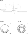
Figur 2- die schematische Darstellung einer bevorzugten Ausführungsform für ein erstes, im Wesentlichen horizontal in der Kolonne angeordnetes Einleitrohr im Bereich der engsten Stelle der Querschnittsverengung im ersten, im Wesentlichen horizontalen Einleitrohr sowie mit einem statischen Mischelement stromabwärts der engsten Stelle der Querschnittsverengung im ersten, im Wesentlichen horizontalen Einleitrohr und
- Figuren 3A und 3B
- Beispiele für bevorzugte Ausführungsformen statischer Mischelemente
- FIG. 1
- the schematic representation of a preferred embodiment of a column according to the invention,
- FIG. 2
- the schematic representation of a preferred embodiment for a first, arranged substantially horizontally in the column inlet tube in the region of the narrowest point of the cross-sectional constriction in the first, substantially horizontal inlet tube and a static Mixing element downstream of the narrowest point of the cross-sectional constriction in the first, substantially horizontal inlet tube and
- FIGS. 3A and 3B
- Examples of preferred embodiments of static mixing elements
Das selektive Lösungsmittel 2 wird über ein im Wesentlichen horizontales Einleitrohr R1 oberhalb der Einbauten E und des Flüssigkeitsverteilers F in die Kolonne eingeleitet. Das im Wesentlichen horizontales Einleitrohr R1 weist eine Geometrie auf, die einen Venturi-Effekt bewirkt, das heißt das Einleitrohr R1 hat eine Querschnittsverengung bis zu einer engsten Stelle, worauf es sich erneut aufweitet, und wobei im Bereich der engsten Stelle der Querschnittsverengung aus einem zweiten Einleitrohr R2 der Rücklauf 7 eingesaugt wird, ohne dass hierfür eine Förderpumpe oder ein statischer Druck erforderlich wäre.The
Die schematische Darstellung in
Bevorzugte geometrische Ausgestaltungen für statische Mischer M sind in den
In einer Extraktivdestillationskolonne K mit einem Innendurchmesser von 5,33 m wird oberhalb von trennwirksamen Einbauten E ein Strom von selektivem Lösungsmittel 2 enthaltend ein N-Methyl-Pyrrolidon/Wasser-Gemisch mit einer Dichte 1013,7 kg/m3 und einer Viskosität von 1,179 mPa·s, mit einem Massenstrom von 417 t/h eingeleitet. Der Rücklauf 7 mit einem Massenstrom von 22 t/h enthält ein Gemisch aus Butanen und Butenen mit einer Dichte von 572,1 kg/m3 und einer Viskosität von 0,14 mPa·s.In an extractive distillation column K with an internal diameter of 5.33 m, above separation-active internals E is a stream of selective solvent 2 containing an N-methyl-pyrrolidone / water mixture having a density of 1013.7 kg / m 3 and a viscosity of 1.179 mPa · s, with a mass flow of 417 t / h initiated. The
Zum Vergleich ist in der Extraktivdestillationskolonne K oberhalb der trennwirksamen Einbauen E ein handelsüblicher Lochboden-Flüssigkeitsverteiler angeordnet. In der Ebene der Öffnungen des Flüssigkeitsaustritts aus dem Flüssigkeitsverteiler beträgt die Mischgüte Xmax/Xav, die wie nachfolgend angegeben definiert wird, 6,8.For comparison, a commercially available perforated bottom liquid distributor is arranged in the extractive distillation column K above the separating incorporations E. In the plane of the openings of the liquid outlet from the liquid distributor, the mixing quality X max / X av , which is defined as indicated below, is 6.8.
Bei der Angabe der Mischgüte bezeichnet Xmax vorliegend den höchsten Wert im Messgebiet für den Massenanteil des Stromes 7,
Xav bezeichnet entsprechend den mittleren Wert im Messgebiet für den Massenanteil des Stromes 7, das heißt den Wert, der bei perfekter Mischung im gesamten Messgebiet zu finden ist.When specifying the mixing quality, X max in the present case denotes the highest value in the measuring region for the mass fraction of the
X av denotes correspondingly the mean value in the measuring area for the mass fraction of the
Die Mischgüte wird durch das Verhältnis Xmax/Xav definiert. Sie ist somit 1 bei idealer Vermischung.The mixing quality is defined by the ratio X max / X av . It is therefore 1 with ideal mixing.
Analog wird das Verhältnis Xmin/Xav definiert, das heißt als Verhältnis aus dem niedrigsten Wert im Messgebiet, bezogen auf den mittleren Wert im Messgebiet, jeweils für den Massenanteil des Stromes 7.Analogously, the ratio X min / X av is defined, that is to say as the ratio of the lowest value in the measuring area, based on the mean value in the measuring area, in each case for the mass fraction of the current 7.
Einmischvorrichtung oberhalb der trennwirksamen Einbauten E ist ein erstes, im Wesentlichen horizontal angeordnetes Einleitrohr R1 vorgesehen, das eine Querschnittsverengung bis zu einer engsten Stelle V aufweist und sich danach erneut aufweitet. Im Bereich der engsten Stelle V der Querschnittsverengung V mündet ein zweites Einleitrohr R2 in dieses ein, taucht teilweise in das erste, im Wesentlichen horizontale Einleitrohr R1 ein und weist ein abgeschrägtes Ende auf.Einmischvorrichtung above the separating internals E is a first, arranged substantially horizontally arranged inlet tube R1, which has a cross-sectional constriction to a narrowest point V and then widening again. In the region of the narrowest point V of the cross-sectional constriction V, a second inlet pipe R2 opens into this, partially immersed in the first, substantially horizontal inlet pipe R1 and has a bevelled end.
Die konkreten Abmessungen sind die Folgenden:
- Durchmesser des ersten, im Wesentlichen horizontalen Einleitrohres R1 = 304,8 mm,
- Querschnittsverengung des ersten, im Wesentlichen horizontalen Einleitrohres R1 über eine Länge von 150 mm in Längsrichtung derselben,
- Bereich der engsten Stelle V der Querschnittsverengung: über 75 mm in Längsrichtung des ersten, im Wesentlichen horizontalen Einleitrohres R1,
- Durchmesser an der engsten Stelle V des ersten, im Wesentlichen horizontalen Einleitrohres R1 = 130 mm,
- woran sich eine Aufweitung bis auf den ursprünglichen Durchmesser, von 304,8 mm über eine Länge von 480 mm des ersten, im Wesentlichen horizontalen Einleitrohres R1, erstreckt.
- Diameter of the first, substantially horizontal inlet tube R1 = 304.8 mm,
- Cross-sectional constriction of the first, substantially horizontal inlet pipe R1 over a length of 150 mm in the longitudinal direction thereof,
- Area of narrowest point V of the cross-sectional constriction: over 75 mm in the longitudinal direction of the first, substantially horizontal inlet pipe R1,
- Diameter at the narrowest point V of the first, substantially horizontal inlet tube R1 = 130 mm,
- followed by an expansion to the original diameter of 304.8 mm over a length of 480 mm of the first substantially horizontal inlet tube R1.
Im Bereich der engsten Stelle V der Querschnittsverengung taucht ein zweites Einleitrohr R2, mit einem Innendurchmesser von 50,8 mm in das erste, im Wesentlichen horizontale Einleitrohres R1, und zwar bis auf eine Eintauchtiefe von 49,2 mm am stromaufwärts gelegenen Ende bzw. bis auf eine Eintauchtiefe von 29,2 mm am stromabwärts gelegenen Ende desselben ein, das heißt, das zweite Einleitrohr R2 ist abgeschrägt.In the region of the narrowest point V of the cross-sectional constriction, a second inlet tube R2, with an internal diameter of 50.8 mm, dips into the first, essentially horizontal inlet tube R1, up to an insertion depth of 49.2 mm at the upstream end or until to an immersion depth of 29.2 mm at the downstream end thereof, that is, the second introducing pipe R2 is chamfered.
In einem Messgebiet, das als Querschnitt des ersten, im Wesentlichen horizontalen Einleitrohres R1, in einer Entfernung von 2 m stromabwärts des stromabwärts gerichteten Endes der engsten Stelle V der Querschnittsverengung definiert wird, werden die folgenden Werte für die Mischgüte ermittelt:
- Xmax/Xav gleich 1,09 und
- Xmin/Xav gleich 0,85.
- X max / X av equals 1.09 and
- X min / X av equals 0.85.
Die Anordnung in Beispiel 2 entspricht der Anordnung in Beispiel 1, wobei jedoch zusätzlich stromabwärts der Einleitrohre R1 und R2 ein statisches Mischelement M angeordnet ist, entsprechend der schematischen Darstellung in
Die Mischgüte ermittelt sich in diesem Fall zu 1,02 für Xmax/Xav bzw. 0,99 für Xmin/Xav.The mixing quality in this case is determined to be 1.02 for X max / X av and 0.99 for X min / X av .
- 11
- Gemisch von Kohlenwasserstoffen und/oder KohlenwasserstoffderivatenMixture of hydrocarbons and / or hydrocarbon derivatives
- 22
- selektives Lösungsmittelselective solvent
- 33
- beladenes, selektives Lösungsmittelloaded, selective solvent
- 44
- Kopfstromtop stream
- 55
- Kondensatcondensate
- 66
- Produktstromproduct flow
- 77
- Rücklaufreturns
- KK
- Kolonnecolumn
- Ee
- trennwirksame Einbautenseparating internals
- FF
- Flüssigkeitsverteilerliquid distributor
- R1R1
- erstes, im Wesentlichen horizontales Einleitrohrfirst, substantially horizontal inlet tube
- R2R2
- zweites Einleitrohrsecond inlet pipe
- VV
- engste Stelle der Querschnittsverengungnarrowest point of the cross-sectional constriction
Claims (14)
- A column (K) comprising separatory internals (E) for separating a mixture of hydrocarbons and/or hydrocarbon derivatives (1) by extractive distillation with a selective solvent (2),
with supply of the selective solvent (2) in the upper region of the column and supply of the mixture of hydrocarbons and/or hydrocarbon derivatives to be separated (1) below the supply of the selective solvent (2), the selective solvent (2) becoming laden in the column (K) with the components from the mixture to be separated (1) for which it has greater affinity and being withdrawn from the lower region of the column as laden selective solvent (3),
while, by contrast, the components from the mixture to be separated for which the selective solvent (2) has a lower affinity remain in the vapor phase and are withdrawn as top stream (4),
which is completely or partially condensed to obtain a condensate (5),
some of which is withdrawn as product stream (6), the remainder being reintroduced to the column (K) as reflux (7),
wherein- said column comprises in the region of the column above the separatory internals (E) a first, substantially horizontal feed pipe (R1) for supplying the selective solvent,- wherein the first, substantially horizontal feed pipe (R1) exhibits a cross-sectional narrowing to a narrowest point (V), said pipe widening again downstream of the cross-sectional narrowing, and wherein- said column comprises a second feed pipe (R2) for supplying the reflux (7), said pipe joining the first, substantially horizontal feed pipe (R1) in the region of the narrowest point (V) of the cross-sectional narrowing. - The column (K) according to claim 1, wherein there is a liquid distributor (F) disposed above the separatory internals (E) in the column (K).
- The column (K) according to either of claims 1 and 2, wherein said column has a diameter of > 0.5 m, in particular a diameter of > 1.0 m.
- The column (K) according to any of claims 1 to 3, wherein the ratio of the cross section of the first, substantially horizontal feed pipe (R1) upstream of the cross-sectional narrowing to the cross section of the first, horizontal feed pipe (R1) at the narrowest point (V) of the cross-sectional narrowing is chosen such that the pressure inside the first, substantially horizontal feed pipe (R1) at the narrowest point (V) of the cross-sectional narrowing is lower than the pressure outside the first, substantially horizontal feed pipe (R1) immediately proximal to the narrowest point (V) of the cross-sectional narrowing.
- The column (K) according to any of claims 1 to 4, wherein the diameter of the first, substantially horizontal feed pipe (R1) upstream of the cross-sectional narrowing is chosen such that the flow velocity in the first, substantially horizontal feed pipe (R1) upstream of the cross-sectional narrowing is in the range of from 0.1 to 5.0 m/s, preferably in the range of from 0.3 to 1.5 m/s.
- The column (K) according to any of claims 1 to 5, wherein the second feed pipe (R2) that joins the first, substantially horizontal feed pipe (R1) in the region of the narrowest point (V) of the cross-sectional narrowing preferably protrudes into said pipe by a protrusion depth of from 0.1 to 0.8 times the diameter of the second feed pipe (R2), preferably by a protrusion depth of from 0.15 to 0.75 times the diameter of the second feed pipe (R2).
- The column (K) according to claim 6, wherein the second feed pipe protruding into the first, substantially horizontal pipe terminates slantedly at an angle to the longitudinal axis of said second feed pipe in the range of from 4° to 65°.
- The column (K) according to any of claims 1 to 7, wherein the first, substantially horizontal feed pipe has disposed in it, downstream of the narrowest point of the cross-sectional narrowing and substantially transversely to the longitudinal axis of said pipe, a static mixing element (M) that partially blocks the cross section of said pipe.
- The column (K) according to claim 8, wherein the static mixing element (M) is spaced apart from the point of the narrowest cross section (V) in the first, substantially horizontal feed pipe (R1) by at least double the diameter of the first, substantially horizontal feed pipe (R1) at the point of the narrowest cross section (V).
- The column (K) according to either of claims 8 and 9, wherein the static mixing element (M) is eccentrically disposed in the cross section of the first, substantially horizontal feed pipe (R1) and is in contact with the interior wall of said pipe or is close to the wall thereof but in the upper region of the first, substantially horizontal feed pipe (R1) is spaced apart from the interior wall of said pipe.
- The column (K) according to claim 10, wherein the static mixing element (M) eccentrically disposed in the first, substantially horizontal feed pipe (R1) is in the shape of an annulus.
- The column (K) according to claim 11, wherein the static mixing element (M) eccentrically disposed in the first, substantially horizontal feed pipe (R1) is in the shape of an annulus which is open at the top, said annulus preferably being secured to the interior wall by means of supports in the upper region of said interior wall.
- A process for separating a mixture of hydrocarbons and/or hydrocarbon derivatives (1) by extractive distillation with a selective solvent (2) in a column (K) according to any of claims 1 to 12,
with supply of the selective solvent (2) in the upper region of the column and supply of the mixture of hydrocarbons and/or hydrocarbon derivatives to be separated (1) below the supply of the selective solvent (2), the selective solvent (2) becoming laden in the column (K) with the components from the mixture to be separated for which it has greater affinity and being withdrawn from the lower region of the column as laden selective solvent (3),
while, by contrast, the components from the mixture of hydrocarbons and/or hydrocarbon derivatives (1) to be separated for which the selective solvent (2) has a lower affinity remain in the vapor phase and are withdrawn as top stream (4),
which is completely or partially condensed to obtain a condensate (5),
some of which is withdrawn as product stream (6), the remainder being reintroduced to the column as reflux (7),
wherein- the selective solvent (2) is supplied into the upper region of the column above the separatory internals (E) via a first, substantially horizontal feed pipe (R1), wherein the first, substantially horizontal feed pipe (R1) exhibits a cross-sectional narrowing to a narrowest point (V), said pipe widening again downstream of the cross-sectional narrowing, and wherein- the reflux (7) is supplied via a second feed pipe (R2) which joins the first, substantially horizontal feed pipe (R1) at the narrowest point (V) of the cross-sectional narrowing. - The process according to claim 13, wherein said process is an extractive distillation of C4 cuts to obtain butanes and/or butenes and/or 1,3-butadiene with a selective solvent selected from N-methylpyrrolidone or mixtures thereof with water, dimethylformamide and acetonitrile or an extractive distillation of aromatics-containing mixtures to obtain benzene and/or toluene and/or xylene.
Applications Claiming Priority (2)
| Application Number | Priority Date | Filing Date | Title |
|---|---|---|---|
| EP14176082 | 2014-07-08 | ||
| PCT/EP2015/065423 WO2016005359A1 (en) | 2014-07-08 | 2015-07-07 | Column with separative installations for separating a mixture of hydrocarbons and/or hydrocarbon derivatives by means of an extractive distillation using a selective solvent |
Publications (2)
| Publication Number | Publication Date |
|---|---|
| EP3166705A1 EP3166705A1 (en) | 2017-05-17 |
| EP3166705B1 true EP3166705B1 (en) | 2018-08-15 |
Family
ID=51063355
Family Applications (1)
| Application Number | Title | Priority Date | Filing Date |
|---|---|---|---|
| EP15734382.3A Active EP3166705B1 (en) | 2014-07-08 | 2015-07-07 | Column with separative installations for separating a mixture of hydrocarbons and/or hydrocarbon derivatives by means of an extractive distillation using a selective solvent |
Country Status (8)
| Country | Link |
|---|---|
| US (1) | US10125063B2 (en) |
| EP (1) | EP3166705B1 (en) |
| JP (1) | JP6759183B2 (en) |
| KR (1) | KR102358867B1 (en) |
| CN (1) | CN106659945B (en) |
| BR (1) | BR112017000028B1 (en) |
| RU (1) | RU2694032C2 (en) |
| WO (1) | WO2016005359A1 (en) |
Families Citing this family (4)
| Publication number | Priority date | Publication date | Assignee | Title |
|---|---|---|---|---|
| KR102086048B1 (en) | 2017-07-07 | 2020-03-06 | 주식회사 엘지화학 | Distribution plate and refining tower including the same |
| US11449577B2 (en) | 2019-11-20 | 2022-09-20 | Micron Technology, Inc. | Methods and apparatus for performing video processing matrix operations within a memory array |
| CN112451993B (en) * | 2020-11-25 | 2022-02-01 | 中国石油化工股份有限公司 | Spray extraction equipment and solvent extraction method |
| CN116999883B (en) * | 2023-08-07 | 2024-04-19 | 江苏诺恩作物科学股份有限公司 | System and method for producing dichlormid |
Family Cites Families (13)
| Publication number | Priority date | Publication date | Assignee | Title |
|---|---|---|---|---|
| US2129684A (en) * | 1934-09-15 | 1938-09-13 | Eastman Kodak Co | Process and apparatus for removing water from aqueous aliphatic acids |
| FR975923A (en) * | 1948-12-31 | 1951-03-12 | Standard Oil Dev Co | Process for the purification of crude aliphatic alcohols |
| AU462261B2 (en) * | 1970-12-29 | 1975-06-19 | SNAMPROGETTI Sp. A | Process for the recovery of aromatic hydrocarbons from mixtures containing the same |
| US4802630A (en) * | 1985-11-19 | 1989-02-07 | Ecolab Inc. | Aspirating foamer |
| FR2606291B1 (en) * | 1986-11-12 | 1990-11-02 | Elf Aquitaine | FRACTIONATION WITH SUPERCRITICAL SOLVENT |
| WO1999003554A1 (en) * | 1997-07-18 | 1999-01-28 | Koch-Glitsch, Inc. | Venturi swirl tube for vapor liquid contact tray |
| DE10219375A1 (en) * | 2002-04-30 | 2003-11-13 | Basf Ag | Continuous process for the extraction of butenes from a C4 cut |
| DE10233620A1 (en) * | 2002-07-24 | 2004-02-12 | Basf Ag | Continuous process for cutting a C4 cut |
| JP3971974B2 (en) | 2002-09-03 | 2007-09-05 | 三菱化学株式会社 | Method for producing (meth) acrylic acids |
| DE10333756A1 (en) * | 2003-07-24 | 2005-02-17 | Basf Ag | Process for the separation of a crude C4 cut |
| ATE518574T1 (en) * | 2007-01-25 | 2011-08-15 | Basf Se | METHOD FOR SEPARATING TRIOXANE FROM A TRIOXANE/FORMALDEHYDE/WATER MIXTURE USING PRESSURE SWING RECTIFICATION |
| DE102010011014A1 (en) * | 2010-03-11 | 2011-09-15 | Basf Se | Process and apparatus for the distillative recovery of pure 1,3-butadiene from crude 1,3-butadiene |
| US9273829B2 (en) | 2012-10-09 | 2016-03-01 | Basf Se | Sorption store for storing gaseous substances |
-
2015
- 2015-07-07 EP EP15734382.3A patent/EP3166705B1/en active Active
- 2015-07-07 WO PCT/EP2015/065423 patent/WO2016005359A1/en active Application Filing
- 2015-07-07 US US15/323,802 patent/US10125063B2/en active Active
- 2015-07-07 KR KR1020177003077A patent/KR102358867B1/en active IP Right Grant
- 2015-07-07 JP JP2017501295A patent/JP6759183B2/en active Active
- 2015-07-07 CN CN201580037020.9A patent/CN106659945B/en active Active
- 2015-07-07 RU RU2017103940A patent/RU2694032C2/en active
- 2015-07-07 BR BR112017000028-8A patent/BR112017000028B1/en active IP Right Grant
Non-Patent Citations (1)
| Title |
|---|
| None * |
Also Published As
| Publication number | Publication date |
|---|---|
| CN106659945B (en) | 2019-07-05 |
| US20170158583A1 (en) | 2017-06-08 |
| JP6759183B2 (en) | 2020-09-23 |
| JP2017521248A (en) | 2017-08-03 |
| BR112017000028B1 (en) | 2021-11-09 |
| WO2016005359A1 (en) | 2016-01-14 |
| EP3166705A1 (en) | 2017-05-17 |
| KR102358867B1 (en) | 2022-02-08 |
| BR112017000028A2 (en) | 2017-10-31 |
| CN106659945A (en) | 2017-05-10 |
| RU2694032C2 (en) | 2019-07-08 |
| RU2017103940A3 (en) | 2019-02-19 |
| RU2017103940A (en) | 2018-08-08 |
| KR20170028964A (en) | 2017-03-14 |
| US10125063B2 (en) | 2018-11-13 |
Similar Documents
| Publication | Publication Date | Title |
|---|---|---|
| EP3166705B1 (en) | Column with separative installations for separating a mixture of hydrocarbons and/or hydrocarbon derivatives by means of an extractive distillation using a selective solvent | |
| DE4433744C2 (en) | Device for mixing media to produce liquid systems | |
| DE60117265T2 (en) | DEVICE AND METHOD FOR MIXING FLUIDS | |
| DE60210765T2 (en) | METHOD FOR MIXING LIQUIDS OR GASES WITH STRONG DIFFERENT VISCOSITY | |
| DE2530012A1 (en) | PROCESS AND DEVICE FOR CONTINUOUS PREPARATION OF WATER / OIL EMULSIONS | |
| DE1296582B (en) | Device for separating substances by foam flotation | |
| EP1749564A2 (en) | Cavitation mixer | |
| EP0873167B1 (en) | Multiphase extractor | |
| WO2007118788A1 (en) | Continuous process for performing a chemical reaction in which a gaseous phase is added to a charge stream comprising one or more solid phases which have been dissolved or dispersed in water | |
| EP2910733B1 (en) | Foam generator for an earth pressure shield tunnel propulsion machine and method for conditioning removed soil material as a support medium for an earth pressure shield | |
| EP2680957B1 (en) | Method and device for mixing two fluid flows | |
| WO2011138162A1 (en) | Mixing process and mixing arrangement | |
| DE2731279A1 (en) | METHOD AND DEVICE FOR DIVIDING A FLOWING LIQUID-GAS MIXTURE INTO SEVERAL SUBSTREAMS | |
| EP2368625A1 (en) | Method and device for dispersion | |
| WO2004098758A1 (en) | Dispersing device | |
| DE2637188C3 (en) | Method and device for the production of foams from plastic | |
| DE2702512C2 (en) | Liquid-liquid contact tray | |
| DE4206715A1 (en) | Mixing or impregnating of liquid flowing in duct with a gas - by introducing gas into liq. such that it is conc. near outer surface of flowing liq., then accelerating mixt. in tapered duct section | |
| DE3233744A1 (en) | Process for mixing a dry mix and water during dry spraying, and mixing tube for the dry-spraying process | |
| DE2527984A1 (en) | METHOD AND DEVICE FOR MULTI-STAGE LIQUID-LIQUID COUNTER-CURRENT EXTRACTION | |
| DE1810041A1 (en) | Method and device for separating a mixture of two different viscous liquids | |
| DE102012006049A1 (en) | Static mixer has input-sided admixing device, downstream mixing device for mixing two or multiple fluid components with different specific gravities, and vertical strands, in which mixing elements are arranged, which passes through mixture | |
| DE102010007303A1 (en) | Method and device for adjusting the concentration of acids or alkalis | |
| DE3935677C2 (en) | ||
| DE2629293A1 (en) | STATIC MIXER |
Legal Events
| Date | Code | Title | Description |
|---|---|---|---|
| STAA | Information on the status of an ep patent application or granted ep patent |
Free format text: STATUS: THE INTERNATIONAL PUBLICATION HAS BEEN MADE |
|
| PUAI | Public reference made under article 153(3) epc to a published international application that has entered the european phase |
Free format text: ORIGINAL CODE: 0009012 |
|
| STAA | Information on the status of an ep patent application or granted ep patent |
Free format text: STATUS: REQUEST FOR EXAMINATION WAS MADE |
|
| 17P | Request for examination filed |
Effective date: 20170208 |
|
| AK | Designated contracting states |
Kind code of ref document: A1 Designated state(s): AL AT BE BG CH CY CZ DE DK EE ES FI FR GB GR HR HU IE IS IT LI LT LU LV MC MK MT NL NO PL PT RO RS SE SI SK SM TR |
|
| AX | Request for extension of the european patent |
Extension state: BA ME |
|
| DAV | Request for validation of the european patent (deleted) | ||
| DAX | Request for extension of the european patent (deleted) | ||
| GRAP | Despatch of communication of intention to grant a patent |
Free format text: ORIGINAL CODE: EPIDOSNIGR1 |
|
| STAA | Information on the status of an ep patent application or granted ep patent |
Free format text: STATUS: GRANT OF PATENT IS INTENDED |
|
| INTG | Intention to grant announced |
Effective date: 20180213 |
|
| RAX | Requested extension states of the european patent have changed |
Extension state: BA Extension state: ME |
|
| GRAS | Grant fee paid |
Free format text: ORIGINAL CODE: EPIDOSNIGR3 |
|
| GRAA | (expected) grant |
Free format text: ORIGINAL CODE: 0009210 |
|
| STAA | Information on the status of an ep patent application or granted ep patent |
Free format text: STATUS: THE PATENT HAS BEEN GRANTED |
|
| DAX | Request for extension of the european patent (deleted) | ||
| AK | Designated contracting states |
Kind code of ref document: B1 Designated state(s): AL AT BE BG CH CY CZ DE DK EE ES FI FR GB GR HR HU IE IS IT LI LT LU LV MC MK MT NL NO PL PT RO RS SE SI SK SM TR |
|
| REG | Reference to a national code |
Ref country code: CH Ref legal event code: EP Ref country code: GB Ref legal event code: FG4D Free format text: NOT ENGLISH Ref country code: AT Ref legal event code: REF Ref document number: 1029092 Country of ref document: AT Kind code of ref document: T Effective date: 20180815 |
|
| REG | Reference to a national code |
Ref country code: IE Ref legal event code: FG4D Free format text: LANGUAGE OF EP DOCUMENT: GERMAN |
|
| REG | Reference to a national code |
Ref country code: DE Ref legal event code: R096 Ref document number: 502015005470 Country of ref document: DE |
|
| REG | Reference to a national code |
Ref country code: NL Ref legal event code: MP Effective date: 20180815 |
|
| REG | Reference to a national code |
Ref country code: LT Ref legal event code: MG4D |
|
| PG25 | Lapsed in a contracting state [announced via postgrant information from national office to epo] |
Ref country code: NO Free format text: LAPSE BECAUSE OF FAILURE TO SUBMIT A TRANSLATION OF THE DESCRIPTION OR TO PAY THE FEE WITHIN THE PRESCRIBED TIME-LIMIT Effective date: 20181115 Ref country code: GR Free format text: LAPSE BECAUSE OF FAILURE TO SUBMIT A TRANSLATION OF THE DESCRIPTION OR TO PAY THE FEE WITHIN THE PRESCRIBED TIME-LIMIT Effective date: 20181116 Ref country code: FI Free format text: LAPSE BECAUSE OF FAILURE TO SUBMIT A TRANSLATION OF THE DESCRIPTION OR TO PAY THE FEE WITHIN THE PRESCRIBED TIME-LIMIT Effective date: 20180815 Ref country code: SE Free format text: LAPSE BECAUSE OF FAILURE TO SUBMIT A TRANSLATION OF THE DESCRIPTION OR TO PAY THE FEE WITHIN THE PRESCRIBED TIME-LIMIT Effective date: 20180815 Ref country code: LT Free format text: LAPSE BECAUSE OF FAILURE TO SUBMIT A TRANSLATION OF THE DESCRIPTION OR TO PAY THE FEE WITHIN THE PRESCRIBED TIME-LIMIT Effective date: 20180815 Ref country code: RS Free format text: LAPSE BECAUSE OF FAILURE TO SUBMIT A TRANSLATION OF THE DESCRIPTION OR TO PAY THE FEE WITHIN THE PRESCRIBED TIME-LIMIT Effective date: 20180815 Ref country code: IS Free format text: LAPSE BECAUSE OF FAILURE TO SUBMIT A TRANSLATION OF THE DESCRIPTION OR TO PAY THE FEE WITHIN THE PRESCRIBED TIME-LIMIT Effective date: 20181215 Ref country code: BG Free format text: LAPSE BECAUSE OF FAILURE TO SUBMIT A TRANSLATION OF THE DESCRIPTION OR TO PAY THE FEE WITHIN THE PRESCRIBED TIME-LIMIT Effective date: 20181115 Ref country code: NL Free format text: LAPSE BECAUSE OF FAILURE TO SUBMIT A TRANSLATION OF THE DESCRIPTION OR TO PAY THE FEE WITHIN THE PRESCRIBED TIME-LIMIT Effective date: 20180815 |
|
| PG25 | Lapsed in a contracting state [announced via postgrant information from national office to epo] |
Ref country code: AL Free format text: LAPSE BECAUSE OF FAILURE TO SUBMIT A TRANSLATION OF THE DESCRIPTION OR TO PAY THE FEE WITHIN THE PRESCRIBED TIME-LIMIT Effective date: 20180815 Ref country code: LV Free format text: LAPSE BECAUSE OF FAILURE TO SUBMIT A TRANSLATION OF THE DESCRIPTION OR TO PAY THE FEE WITHIN THE PRESCRIBED TIME-LIMIT Effective date: 20180815 Ref country code: HR Free format text: LAPSE BECAUSE OF FAILURE TO SUBMIT A TRANSLATION OF THE DESCRIPTION OR TO PAY THE FEE WITHIN THE PRESCRIBED TIME-LIMIT Effective date: 20180815 |
|
| PG25 | Lapsed in a contracting state [announced via postgrant information from national office to epo] |
Ref country code: PL Free format text: LAPSE BECAUSE OF FAILURE TO SUBMIT A TRANSLATION OF THE DESCRIPTION OR TO PAY THE FEE WITHIN THE PRESCRIBED TIME-LIMIT Effective date: 20180815 Ref country code: EE Free format text: LAPSE BECAUSE OF FAILURE TO SUBMIT A TRANSLATION OF THE DESCRIPTION OR TO PAY THE FEE WITHIN THE PRESCRIBED TIME-LIMIT Effective date: 20180815 Ref country code: ES Free format text: LAPSE BECAUSE OF FAILURE TO SUBMIT A TRANSLATION OF THE DESCRIPTION OR TO PAY THE FEE WITHIN THE PRESCRIBED TIME-LIMIT Effective date: 20180815 Ref country code: RO Free format text: LAPSE BECAUSE OF FAILURE TO SUBMIT A TRANSLATION OF THE DESCRIPTION OR TO PAY THE FEE WITHIN THE PRESCRIBED TIME-LIMIT Effective date: 20180815 Ref country code: CZ Free format text: LAPSE BECAUSE OF FAILURE TO SUBMIT A TRANSLATION OF THE DESCRIPTION OR TO PAY THE FEE WITHIN THE PRESCRIBED TIME-LIMIT Effective date: 20180815 Ref country code: IT Free format text: LAPSE BECAUSE OF FAILURE TO SUBMIT A TRANSLATION OF THE DESCRIPTION OR TO PAY THE FEE WITHIN THE PRESCRIBED TIME-LIMIT Effective date: 20180815 |
|
| REG | Reference to a national code |
Ref country code: DE Ref legal event code: R097 Ref document number: 502015005470 Country of ref document: DE |
|
| PG25 | Lapsed in a contracting state [announced via postgrant information from national office to epo] |
Ref country code: SM Free format text: LAPSE BECAUSE OF FAILURE TO SUBMIT A TRANSLATION OF THE DESCRIPTION OR TO PAY THE FEE WITHIN THE PRESCRIBED TIME-LIMIT Effective date: 20180815 Ref country code: DK Free format text: LAPSE BECAUSE OF FAILURE TO SUBMIT A TRANSLATION OF THE DESCRIPTION OR TO PAY THE FEE WITHIN THE PRESCRIBED TIME-LIMIT Effective date: 20180815 Ref country code: SK Free format text: LAPSE BECAUSE OF FAILURE TO SUBMIT A TRANSLATION OF THE DESCRIPTION OR TO PAY THE FEE WITHIN THE PRESCRIBED TIME-LIMIT Effective date: 20180815 |
|
| PLBE | No opposition filed within time limit |
Free format text: ORIGINAL CODE: 0009261 |
|
| STAA | Information on the status of an ep patent application or granted ep patent |
Free format text: STATUS: NO OPPOSITION FILED WITHIN TIME LIMIT |
|
| 26N | No opposition filed |
Effective date: 20190516 |
|
| PG25 | Lapsed in a contracting state [announced via postgrant information from national office to epo] |
Ref country code: SI Free format text: LAPSE BECAUSE OF FAILURE TO SUBMIT A TRANSLATION OF THE DESCRIPTION OR TO PAY THE FEE WITHIN THE PRESCRIBED TIME-LIMIT Effective date: 20180815 |
|
| PG25 | Lapsed in a contracting state [announced via postgrant information from national office to epo] |
Ref country code: MC Free format text: LAPSE BECAUSE OF FAILURE TO SUBMIT A TRANSLATION OF THE DESCRIPTION OR TO PAY THE FEE WITHIN THE PRESCRIBED TIME-LIMIT Effective date: 20180815 |
|
| REG | Reference to a national code |
Ref country code: CH Ref legal event code: PL |
|
| GBPC | Gb: european patent ceased through non-payment of renewal fee |
Effective date: 20190707 |
|
| PG25 | Lapsed in a contracting state [announced via postgrant information from national office to epo] |
Ref country code: TR Free format text: LAPSE BECAUSE OF FAILURE TO SUBMIT A TRANSLATION OF THE DESCRIPTION OR TO PAY THE FEE WITHIN THE PRESCRIBED TIME-LIMIT Effective date: 20180815 |
|
| REG | Reference to a national code |
Ref country code: BE Ref legal event code: MM Effective date: 20190731 |
|
| PG25 | Lapsed in a contracting state [announced via postgrant information from national office to epo] |
Ref country code: GB Free format text: LAPSE BECAUSE OF NON-PAYMENT OF DUE FEES Effective date: 20190707 |
|
| PG25 | Lapsed in a contracting state [announced via postgrant information from national office to epo] |
Ref country code: BE Free format text: LAPSE BECAUSE OF NON-PAYMENT OF DUE FEES Effective date: 20190731 Ref country code: LU Free format text: LAPSE BECAUSE OF NON-PAYMENT OF DUE FEES Effective date: 20190707 Ref country code: LI Free format text: LAPSE BECAUSE OF NON-PAYMENT OF DUE FEES Effective date: 20190731 Ref country code: CH Free format text: LAPSE BECAUSE OF NON-PAYMENT OF DUE FEES Effective date: 20190731 |
|
| PG25 | Lapsed in a contracting state [announced via postgrant information from national office to epo] |
Ref country code: FR Free format text: LAPSE BECAUSE OF NON-PAYMENT OF DUE FEES Effective date: 20190731 Ref country code: PT Free format text: LAPSE BECAUSE OF FAILURE TO SUBMIT A TRANSLATION OF THE DESCRIPTION OR TO PAY THE FEE WITHIN THE PRESCRIBED TIME-LIMIT Effective date: 20181215 |
|
| PG25 | Lapsed in a contracting state [announced via postgrant information from national office to epo] |
Ref country code: IE Free format text: LAPSE BECAUSE OF NON-PAYMENT OF DUE FEES Effective date: 20190707 |
|
| PG25 | Lapsed in a contracting state [announced via postgrant information from national office to epo] |
Ref country code: CY Free format text: LAPSE BECAUSE OF FAILURE TO SUBMIT A TRANSLATION OF THE DESCRIPTION OR TO PAY THE FEE WITHIN THE PRESCRIBED TIME-LIMIT Effective date: 20180815 |
|
| PG25 | Lapsed in a contracting state [announced via postgrant information from national office to epo] |
Ref country code: HU Free format text: LAPSE BECAUSE OF FAILURE TO SUBMIT A TRANSLATION OF THE DESCRIPTION OR TO PAY THE FEE WITHIN THE PRESCRIBED TIME-LIMIT; INVALID AB INITIO Effective date: 20150707 Ref country code: MT Free format text: LAPSE BECAUSE OF FAILURE TO SUBMIT A TRANSLATION OF THE DESCRIPTION OR TO PAY THE FEE WITHIN THE PRESCRIBED TIME-LIMIT Effective date: 20180815 |
|
| REG | Reference to a national code |
Ref country code: AT Ref legal event code: MM01 Ref document number: 1029092 Country of ref document: AT Kind code of ref document: T Effective date: 20200707 |
|
| PG25 | Lapsed in a contracting state [announced via postgrant information from national office to epo] |
Ref country code: AT Free format text: LAPSE BECAUSE OF NON-PAYMENT OF DUE FEES Effective date: 20200707 |
|
| PG25 | Lapsed in a contracting state [announced via postgrant information from national office to epo] |
Ref country code: MK Free format text: LAPSE BECAUSE OF FAILURE TO SUBMIT A TRANSLATION OF THE DESCRIPTION OR TO PAY THE FEE WITHIN THE PRESCRIBED TIME-LIMIT Effective date: 20180815 |
|
| PGFP | Annual fee paid to national office [announced via postgrant information from national office to epo] |
Ref country code: DE Payment date: 20230726 Year of fee payment: 9 |