EP3166664B1 - Dual syringe with percutaneous cannula - Google Patents
Dual syringe with percutaneous cannula Download PDFInfo
- Publication number
- EP3166664B1 EP3166664B1 EP15818817.7A EP15818817A EP3166664B1 EP 3166664 B1 EP3166664 B1 EP 3166664B1 EP 15818817 A EP15818817 A EP 15818817A EP 3166664 B1 EP3166664 B1 EP 3166664B1
- Authority
- EP
- European Patent Office
- Prior art keywords
- syringe
- cannula
- port
- dual
- attachment member
- Prior art date
- Legal status (The legal status is an assumption and is not a legal conclusion. Google has not performed a legal analysis and makes no representation as to the accuracy of the status listed.)
- Active
Links
Images


Classifications
-
- A—HUMAN NECESSITIES
- A61—MEDICAL OR VETERINARY SCIENCE; HYGIENE
- A61B—DIAGNOSIS; SURGERY; IDENTIFICATION
- A61B10/00—Instruments for taking body samples for diagnostic purposes; Other methods or instruments for diagnosis, e.g. for vaccination diagnosis, sex determination or ovulation-period determination; Throat striking implements
- A61B10/02—Instruments for taking cell samples or for biopsy
- A61B10/0233—Pointed or sharp biopsy instruments
- A61B10/0283—Pointed or sharp biopsy instruments with vacuum aspiration, e.g. caused by retractable plunger or by connected syringe
-
- A—HUMAN NECESSITIES
- A61—MEDICAL OR VETERINARY SCIENCE; HYGIENE
- A61B—DIAGNOSIS; SURGERY; IDENTIFICATION
- A61B10/00—Instruments for taking body samples for diagnostic purposes; Other methods or instruments for diagnosis, e.g. for vaccination diagnosis, sex determination or ovulation-period determination; Throat striking implements
- A61B10/02—Instruments for taking cell samples or for biopsy
- A61B10/0233—Pointed or sharp biopsy instruments
-
- A—HUMAN NECESSITIES
- A61—MEDICAL OR VETERINARY SCIENCE; HYGIENE
- A61B—DIAGNOSIS; SURGERY; IDENTIFICATION
- A61B10/00—Instruments for taking body samples for diagnostic purposes; Other methods or instruments for diagnosis, e.g. for vaccination diagnosis, sex determination or ovulation-period determination; Throat striking implements
- A61B10/02—Instruments for taking cell samples or for biopsy
- A61B10/0233—Pointed or sharp biopsy instruments
- A61B10/0266—Pointed or sharp biopsy instruments means for severing sample
- A61B10/0275—Pointed or sharp biopsy instruments means for severing sample with sample notch, e.g. on the side of inner stylet
-
- A—HUMAN NECESSITIES
- A61—MEDICAL OR VETERINARY SCIENCE; HYGIENE
- A61M—DEVICES FOR INTRODUCING MEDIA INTO, OR ONTO, THE BODY; DEVICES FOR TRANSDUCING BODY MEDIA OR FOR TAKING MEDIA FROM THE BODY; DEVICES FOR PRODUCING OR ENDING SLEEP OR STUPOR
- A61M5/00—Devices for bringing media into the body in a subcutaneous, intra-vascular or intramuscular way; Accessories therefor, e.g. filling or cleaning devices, arm-rests
- A61M5/178—Syringes
- A61M5/19—Syringes having more than one chamber, e.g. including a manifold coupling two parallelly aligned syringes through separate channels to a common discharge assembly
-
- A—HUMAN NECESSITIES
- A61—MEDICAL OR VETERINARY SCIENCE; HYGIENE
- A61M—DEVICES FOR INTRODUCING MEDIA INTO, OR ONTO, THE BODY; DEVICES FOR TRANSDUCING BODY MEDIA OR FOR TAKING MEDIA FROM THE BODY; DEVICES FOR PRODUCING OR ENDING SLEEP OR STUPOR
- A61M5/00—Devices for bringing media into the body in a subcutaneous, intra-vascular or intramuscular way; Accessories therefor, e.g. filling or cleaning devices, arm-rests
- A61M5/178—Syringes
- A61M5/31—Details
- A61M5/32—Needles; Details of needles pertaining to their connection with syringe or hub; Accessories for bringing the needle into, or holding the needle on, the body; Devices for protection of needles
- A61M5/3293—Needles; Details of needles pertaining to their connection with syringe or hub; Accessories for bringing the needle into, or holding the needle on, the body; Devices for protection of needles characterised by features of the needle hub
-
- A—HUMAN NECESSITIES
- A61—MEDICAL OR VETERINARY SCIENCE; HYGIENE
- A61B—DIAGNOSIS; SURGERY; IDENTIFICATION
- A61B10/00—Instruments for taking body samples for diagnostic purposes; Other methods or instruments for diagnosis, e.g. for vaccination diagnosis, sex determination or ovulation-period determination; Throat striking implements
- A61B10/02—Instruments for taking cell samples or for biopsy
- A61B10/0233—Pointed or sharp biopsy instruments
- A61B10/025—Pointed or sharp biopsy instruments for taking bone, bone marrow or cartilage samples
- A61B2010/0258—Marrow samples
Definitions
- the present invention relates to the field of medical devices, specifically syringes and aspirating cannulas.
- Autologous stem cell transplant generally occurs in a highly sterile environment such as available in an operating room or ambulatory surgical center.
- One of the common methods to obtain stem cells is through the use of aspirating cannulas.
- cannulas require a second instrument to access the interior of the body for collection of the stem cells.
- extraction of bone marrow stem cells generally requires the insertion of a trocar and the cannula after the trocar is in place.
- extraction of stem cells from adipose tissues generally requires a scalpel incision into the patient before insertion of the aspirating cannula.
- the desired cells and tissues are harvested by the cannula, the cells or tissues are then transferred to syringes or test tubes. These transfers significantly increase the opportunity for sterile breaks through introduction of manual transfers.
- An invention and method is desired to simply extract and collect desired cells from a patient in a sterile closed system and then reintroduce the concentrated cells for therapeutic purposes.
- US3,978,846 discloses a syringe including a first tubular body and a second tubular body.
- US2008/0167621 discloses a syringe including a multi-barrel body.
- the invention is defined by the claims.
- the present invention simplifies the process for autologous stem cell transplant by utilization of a dual syringe with percutaneous aspirating cannula that safely harvests cells and tissues without the need for a surgical procedure and by minimizing the opportunity for a sterile break.
- the percutaneous aspirating cannula utilizes a needle and a tapered edge cannula wherein the needle and tapered edge allow for the percutaneous aspirating cannula to be inserted directly into a patient without the need of surgical incision or insertion of a trocar.
- the dual syringe is a closed system that allows for the harvesting syringe to harvest the cells/tissue which is then centrifuged to aggregate the cells wherein the isolated cell pellet is then transferred to a second syringe where it can then be reinjected to the patient for a desired therapeutic purpose.
- the dual syringe 1 comprises a harvesting syringe 10 and a transfer syringe 100.
- the harvesting syringe 10 comprises a barrel 20, spacer 70, and harvesting plunger 90.
- the barrel 20 comprises a partially cylindrical sidewall 21 and bottom wall 30 that define an interior cavity 60.
- the side wall 21 is shaped so that it forms a hemi-cylindrical groove 22 that extends from the top end 23 of the harvesting syringe 10 to the bottom end 24.
- the preferred embodiment of the groove is hemi-cylindrical but other shapes such as triangular or rectangular are envisioned.
- On the opposing end of the barrel 20 from the bottom wall 30 is an opening 40.
- Handles 25 extend perpendicularly from the cylindrical sidewall 21 and away from the opening 40 at the top end 23 of the barrel 20. The handles 25 are positioned 90 degrees from the hemi-cylindrical groove 22.
- the interior surface 26 is of the cylindrical sidewall 21 is generally smooth and corresponds in shape to the exterior surface 27 which includes the hemi-cylindrical groove 22.
- a ridge 28 is located along the interior surface 26 of the cylindrical sidewall 21 near the top end 23.
- the cylindrical sidewall 21 is generally translucent and contains identifying markings 29 to indicate the volume of material within the interior cavity 60.
- a tubular shaped spacer 70 having a cylindrical sidewall 71, a bottom wall 72, and top wall 73 is positioned within the hemi-cylindrical groove 22 such that the bottom wall 72 of the spacer 70 and bottom wall 30 of the harvesting syringe 10 are aligned.
- the top wall 73 of the spacer 70 is positioned approximately at the midpoint of the hemi-cylindrical groove 22 of the harvesting syringe 10.
- An interior channel 74 extends from the top wall 73 to the bottom wall 72 of the spacer 70A top port 75 is positioned on the top wall 73 which creates a fluid pathway with channel 74.
- a syringe locking mechanism 76 having a channel 78 through its center is positioned on the top wall 73 above the top port 75.
- the syringe locking mechanism 76 may be female luer taper connection.
- a bottom port 77 is positioned on the bottom wall 72.
- a fluid pathway exists from the bottom port 76, through the channel 74, through the top port 75 and through the channel 78 of the syringe locking mechanism 76.
- the spacer 70 may be bonded, glued, or welded onto the barrel 20. Alternatively, the spacer 70 and barrel 21 may be integral.
- the harvesting syringe 10 has an outflow port 31 positioned approximately in the middle of the of the bottom wall 30 and an inflow port 32 positioned in a portion of the bottom wall 30 opposite from the spacer 70 and aligned with the bottom port 77 and the outflow port 31. Both the inflow port 31 and outflow port 31 create a fluid pathway into the interior cavity 60 of the barrel 20.
- a needle attachment 34 positioned on the exterior surface 33 of the bottom wall 30, has a channel 41 through its center such that a fluid pathway exists with the inflow port 32.
- the needle attachment 34 may be a male luer taper connection.
- On the exterior surface 33 of the bottom wall 30 a transfer wall 35 is formed around the outflow port 31 and transfer port 77.
- a transfer cover 36 is attached to the transfer wall 35 and covers the outflow port 31 and transfer port 77. The transfer wall 35 and transfer cover 36 create a pathway 38 between the outflow port 31 and transfer port 77.
- the interior surface 37 of the bottom wall 30 is sloped such that the interior surface 37 is shaped to funnel contents into the outflow port 31.
- the exterior surface 33 of the bottom wall 30 corresponds to the same slope of the interior surface 37.
- the pathway 38 may be selectively closed by a valve 39.
- the harvesting plunger 90 has a stopper or harvesting plunger head 91 connected to one end of a shaft 92.
- the opposing end of the shaft 92 has a handle 93which is shaped to generally correspond with the interior surface 26 of the cylindrical sidewall 31, including the hemi-cylindrical groove 22.
- the harvesting plunger head 91 is shaped to correspond with the interior surface 26 of the cylindrical sidewall 31 including the hemi-cylindrical groove 22.
- the shaft 92 is screwed into the plunger head 91 and the friction created by the plunger head 91 and the interior surface 26 generally holds the plunger head 91 in place which allows the shaft 92 to be screwed in or out.
- the harvesting plunger head 91 is made of a malleable material such as a hard rubber to create a seal between the interior cavity 60 of the barrel 20 and the atmospheric environment existing above the plunger head 91.
- the ridge 28 on the interior surface 26 inhibits removal of the harvesting plunger head 91 from the interior cavity 60 of the barrel 20.
- the transfer syringe 100 comprises a barrel 101 and a transfer plunger 110.
- the barrel 101 is translucent and contains identifying markings 102 to indicate the volume of material within the barrel 101.
- the transfer syringe barrel 101 comprises a cylindrical sidewall 103 having an open top end 104 and a closed bottom end 105.
- a handle 106 extends from the barrel 101 at its top end 104.
- a port 107 is positioned in the bottom end 105 of the syringe barrel 101 to allow access into the interior cavity 108 of the barrel 101.
- a needle attachment 109 having a channel through its center is affixed to exterior surface of the bottom end 105.
- the needle attachment 109 may be a male luer taper connection.
- a fluid pathway exists between the channel of the needle attachment 109, port 107, and interior cavity 108.
- the percutaneous cannula assembly 200 is composed of a needle hub 210, a needle 201, and a removable cannula 250.
- the hollow tubular needle 201 is comprised of cylindrical sidewall 202 having a beveled point 203 on one end and an opening 204 on the opposing end.
- a cavity 205 is formed by the cylindrical sidewall 202 and extends from the beveled point 203 to the opening 204.
- the needle hub 210 contains a syringe connecting portion 211 and a cannula connecting portion 230.
- the syringe connecting portion 211 consists of a cylindrical sidewall 212 having a connecting outlet 213 on one end and a needle receiving outlet 214 on the opposing end.
- a radial flange 217 is positioned around the connecting outlet 213 on the exterior face 216 of the cylindrical sidewall 212.
- the radial flange 217 may be consistent with a female luer taper connection.
- a cavity 215 is formed by the cylindrical sidewall 212 and extends from the connecting outlet 213 on one end and a needle receiving outlet 214..
- the needle 201 is permanently affixed to at least a portion of the interior face of the cylindrical sidewall 212.
- Two wings 218 extend radially away from the exterior face 216 of the cylindrical sidewall 212.
- the wings 218 permit a user to grip and rotate the needle hub 210.
- the wings 218 are positioned on the exterior face 216 of the cylindrical sidewall 212 at a sufficient distance away from the radial flange 217 to allow the radial flange 217 to connect to the needle attachment 34 and be screwed or positioned into place.
- a fluid communication pathway exists from the connecting outlet 213 to the beveled point 203 of the needle 201.
- the cannula connecting portion 230 consists of a cylindrical sidewall 231 having a connecting end 232 on one end and a cannula receiving end 233 on the opposing end.
- the diameter of the cylindrical sidewall 231 of the cannula connecting portion 230 is greater than the cylindrical sidewall 212 of the syringe connecting portion 211.
- the connecting end 232 is attached to the exterior face 216 of the cylindrical sidewall 212 of the syringe connecting portion 211 at the approximate midpoint of the cylindrical sidewall 212 of the syringe connecting portion 211.
- Threads 234 are positioned on the interior face 234 of the cylindrical sidewall 231 of the cannula connecting portion 230.
- Threads 234 may be consistent with a male luer lock taper connection.
- Radial ridges 236 are positioned on the external face 237 of the cylindrical sidewall 231 of the cannula connecting portion 230. The radial ridges 236 assist in gripping the needle hub 210.
- the distance between the interior face 234 of the cylindrical sidewall 231 of the cannula connecting portion 230 and the exterior face 216 of the cylindrical sidewall 212 of the syringe connecting portion 211 is of sufficient distance that a cannula or other syringe may be removably attached to the needle hub 210.
- the cannula 250 is comprised of a tubular shaft 251 attached to a cannula hub 252.
- the cannula hub 252 is tubular in shape with a generally cylindrical sidewall 253 with a cannula receiving portion 254 on one end and outlet 255 on the opposing end.
- a radial flange 256 is positioned around the outlet 255 of the cylindrical sidewall 253.
- the radial flange 256 may be consistent with a female luer taper connection.
- One end of the tubular shaft 251 is attached to the cannula hub 252 at the cannula receiving portion 254.
- the other end of the tubular shaft 251 is a tapered outlet 258.
- the cylindrical sidewall 253 and cannula shaft 251 form a cavity 257 between the outlet 255 and the tapered outlet 258.
- the cannula shaft 251 and the tapered outlet 258 have an inner diameter large enough to allow the needle 201 to pass through.
- Ports 259 extend longitudinally through the sidewall of the tubular shaft 251. Ports 259 may have smooth edges for minimal tissue cleavage or sharp skived edges for maximum tissue recovery depending on the desired use and desired tissue and/or cells to harvest. Ports 259 may be oriented on one side or may extend generally around the circumference of the tubular shaft 251. Depth markings 260 are positioned along the outer face of the cannula shaft 251 that indicate the distance from the respective marking to the tapered outlet 258.
- the transfer syringe 100 is attached to the harvesting syringe 10 through attachment of the needle attachment 109 to the syringe locking mechanism 76 of the spacer 70.
- the barrel 101 of the transfer syringe 100 partially fits within the hemi-cylindrical groove 22 of the harvesting syringe 10.
- the harvesting plunger head 91 is shaped to not interfere with the transfer syringe 100 or to prohibit the screwing in of the transfer syringe 100 onto the syringe locking mechanism 76.
- a pathway is created between the interior cavity 60 of the harvesting syringe 10 and the interior cavity 108 of the transfer syringe 100 by the outflow port 31, pathway 38, bottom port 77, interior cavity 74 of the spacer 70, top port 75, needle attachment 109, and port 107.
- the pathway 38 may be selectively closed by a valve 39.
- Valve 39 may designed as a pressure sensitive valve which seals with positive pressure from outflow port 31 but opens upon negative pressure from the bottom port 77.
- the needle hub 210 may attach to the dual syringe 1 through mating of needle attachment 34 of the dual syringe 1 and ridge 217 of the needle hub assembly 210.
- the cannula 250 may attach to the needle hub 210 through mating of the cannula connecting portion 230 and radial flange 256 of the cannula 250.
- the needle 201 extends out the tapered outlet 258 of the cannula 250 when the cannula 250 is attached to the needle hub 210. As seen in FIG.
- the cannula 250 may also attach to the dual syringe 1 through mating of needle attachment 34 of the dual syringe 1 and radial flange 256 of the cannula 250.
- the attachments are luer lock taper connections although alternative embodiments may use a luer slip taper connection.
- the broad process 300 of operation of the dual syringe 1 comprises the following steps:
- the dual syringe 1, with the attached transfer syringe 100 (with the transfer plunger 110 fully depressed) and the percutaneous cannula assembly 200, is inserted into tissue or bone of a patient to harvest the desired cells.
- the beveled point 203 of the needle 201 along with the cannula 250 inserts percutaneously through patient's skin and advanced into the patient until the appropriate depth as indicated by the depth markings 260 on the cannula 250.
- the tapered outlet 255 of the cannula 250 assists insertion into the patient's skin to reduce any catching or blunt trauma.
- the cannula 250 is unmated from the needle hub assembly 210 which allows for the removal of the dual syringe 1 (with the needle hub assembly 210 still attached) from the cannula 250.
- the needle hub assembly 210 is unmated from the harvesting syringe 10.
- the harvesting syringe is then attached to the cannula 250 through mating the needle attachment 34 of the dual syringe 1 and ridge 256 of the cannula 250. This establishes a fluid communication pathway from the tapered outlet 258 and ports 259, through the tubular shaft 251, through the cannula hub 252, through the outlet 255, through the inflow port 32, and into the barrel 20 of the harvesting syringe 10.
- the cannula 250 may then be used as a standard aspirating cannula to harvest the desired cells.
- the user creates negative pressure within barrel 20 by pulling on the harvesting plunger 90 to draw in cells and tissues while simultaneously moving the cannula within the patient's body at the desired location.
- the ports 259 and tapered outlet 258 shear and collect cells/tissue which are then drawn into the cannula 250 and are ultimately drawn into the barrel 20.
- the harvesting syringe 10 (with the cannula 250 still attached) is removed from the patient.
- the cannula 250 is removed 270 from the harvesting syringe 10.
- the shaft 92 is unscrewed from the plunger head 91 and removed from the harvesting syringe 10.
- a standard syringe port cap is attached to the needle attachment 34 to seal inflow port 32. The cap ensures sterility and prevents migration of the cell pellet into the inflow port 32.
- the dual syringe 1 is placed in a centrifuge and spun at approximately 500 to 2000 g forces for a period of 3 to 20 minutes. Centrifugation causes the aspirated cells to separate from the aspirated fluid. As a result of the funnel shape of the bottom wall 30, the cells, denser than the fluid, form a pellet on the bottom wall 30 near the outflow port 31.
- the valve 39 remains closed due to the positive pressure exerted from the outflow port 31 which prevents any of the contents of the barrel from migrating through pathway 38 and/or through the bottom port 77 of the spacer 70.
- the dual syringe 1 is removed from the centrifuge.
- the transfer plunger 110 is pulled away from the bottom end 105 which creates negative pressure within the interior cavity 108 of the transfer syringe 100.
- This negative pressure opens the valve 39 to allow cells of the pellet to move through the outflow port 31, through the pathway 38, through the interior cavity 74 of the spacer 70, through the top port 75, through the port 107 of the transfer syringe and into the interior cavity 108 of the transfer syringe 100.
- the harvesting plunger may be manually depressed, after reattachment of the shaft 92, by the user in conjunction with user's pulling of the transfer plunger 110.
- the transfer syringe 100 is removed from the syringe locking mechanism 76 and a standard hypodermic needle is attached to the transfer syringe 100 at the needle attachment 109 as seen in FIG. 14 .
- the gauge and design of the needle for the transfer syringe may depend on the type of tissue delivered, the tissue the needle needs to penetrate to deliver the cells and the volume of the cells to be delivered. Saline and/or other chemicals may be added to reconstitute the cell pellet in the transfer syringe 100.
- the transfer syringe 100 is then inserted into a patient in a specific location for delivery of the harvested cells for therapeutic purposes.
- ports 259 may vary depending on the type of tissue harvested, the tissue the needle needs to penetrate to acquire the tissue, and the volume of the tissue needed.
- the dual syringe may be used with a standard aspirating cannula as well with traditional access to the cells created through trocar use or surgical incision. Once the cells are harvested, the dual syringe is removed from the patient. The standard aspirating cannula is removed 270 from the harvesting syringe 10. The shaft 92 is unscrewed from the plunger head 91 and removed from the harvesting syringe 10.. A standard syringe port cap is attached to the needle attachment 34 to seal inflow port 32. The dual syringe 1 is placed in a centrifuge and spun at approximately 500 to 2000 g forces for a period of 3 to 20 minutes. Centrifugation causes the aspirated cells to separate from the aspirated fluid.
- the cells denser than the fluid, form a pellet on the bottom wall 30 near the outflow port 31.
- the valve 39 remains closed due to the positive pressure exerted from the outflow port 31 which prevents any of the contents of the barrel from migrating through pathway 38 and/or through the bottom port 77 of the spacer 70.
- the dual syringe 1 is removed from the centrifuge.
- the transfer plunger 110 is pulled away from the bottom end 105 which creates negative pressure within the interior cavity 108 of the transfer syringe 100.
- This negative pressure opens the valve 39 to allow cells of the pellet to move through the outflow port 31, through the pathway 38, through the interior cavity 74 of the spacer 70, through the top port 75, through the port 107 of the transfer syringe and into the interior cavity 108 of the transfer syringe 100.
- the harvesting plunger may be manually depressed, after reattachment of the shaft 92, by the user in conjunction with user's pulling of the transfer plunger 110.
- the transfer syringe 100 is removed from the syringe locking mechanism 76 and a standard hypodermic needle is attached to the transfer syringe 100 at the needle attachment 109 as seen in FIG. 14 .
- the gauge and design of the needle for the transfer syringe may depend on the type of tissue delivered, the tissue the needle needs to penetrate to deliver the cells and the volume of the cells to be delivered. Saline and/or other chemicals may be added to reconstitute the cell pellet in the transfer syringe 100.
- the transfer syringe 100 is then inserted into a patient in a specific location for delivery of the harvested cells for therapeutic purposes.
- the above device may be used for autologous stem cell transplantation in an office setting as described in FIG. 15 .
- a healthcare provider may utilize local anesthetic at the specific harvesting site or general anesthetic for the harvesting of stem cells. Stem cell harvesting may occur through adipose tissue in a patient's abdominal region, or through adipose tissue in another adipose-rich region such as the inner thigh or through a patient's bone marrow.
- the healthcare provider utilizes the sterile dual syringe and attaches the percutaneous cannula 200.
- the healthcare provider inserts the dual syringe 1 with the percutaneous cannula 200 as described in FIG.
- the harvesting syringe 10, transfer syringe 100, percutaneous cannula assembly 200, syringe port cap, and hypodermic needle 50 are sterile and stored in a single use sterile packaging kit.
- the packaged unit is designed for singular use for a single patient for transplantation of autologous tissue.
Landscapes
- Health & Medical Sciences (AREA)
- Life Sciences & Earth Sciences (AREA)
- Veterinary Medicine (AREA)
- Animal Behavior & Ethology (AREA)
- Biomedical Technology (AREA)
- Heart & Thoracic Surgery (AREA)
- Engineering & Computer Science (AREA)
- Public Health (AREA)
- General Health & Medical Sciences (AREA)
- Medical Informatics (AREA)
- Surgery (AREA)
- Molecular Biology (AREA)
- Pathology (AREA)
- Vascular Medicine (AREA)
- Anesthesiology (AREA)
- Hematology (AREA)
- Infusion, Injection, And Reservoir Apparatuses (AREA)
Description
- This application claims the benefit of
U.S. provisional applications Serial No. 62/022,511 filed July 9, 2014 62/092,022 filed December 15, 2014 - Not applicable.
- The present invention relates to the field of medical devices, specifically syringes and aspirating cannulas.
- Autologous stem cell transplant generally occurs in a highly sterile environment such as available in an operating room or ambulatory surgical center. One of the common methods to obtain stem cells is through the use of aspirating cannulas. However, cannulas require a second instrument to access the interior of the body for collection of the stem cells. For example, extraction of bone marrow stem cells generally requires the insertion of a trocar and the cannula after the trocar is in place. Similarly, extraction of stem cells from adipose tissues generally requires a scalpel incision into the patient before insertion of the aspirating cannula. Moreover, once the desired cells and tissues are harvested by the cannula, the cells or tissues are then transferred to syringes or test tubes. These transfers significantly increase the opportunity for sterile breaks through introduction of manual transfers. An invention and method is desired to simply extract and collect desired cells from a patient in a sterile closed system and then reintroduce the concentrated cells for therapeutic purposes.
-
US3,978,846 discloses a syringe including a first tubular body and a second tubular body.US2008/0167621 discloses a syringe including a multi-barrel body. - The invention is defined by the claims. The present invention simplifies the process for autologous stem cell transplant by utilization of a dual syringe with percutaneous aspirating cannula that safely harvests cells and tissues without the need for a surgical procedure and by minimizing the opportunity for a sterile break. The percutaneous aspirating cannula utilizes a needle and a tapered edge cannula wherein the needle and tapered edge allow for the percutaneous aspirating cannula to be inserted directly into a patient without the need of surgical incision or insertion of a trocar. The dual syringe is a closed system that allows for the harvesting syringe to harvest the cells/tissue which is then centrifuged to aggregate the cells wherein the isolated cell pellet is then transferred to a second syringe where it can then be reinjected to the patient for a desired therapeutic purpose.
-
-
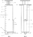
FIG. 1 is a side profile of the harvesting syringe. -
FIG. 2 is a front profile of the harvesting syringe. -
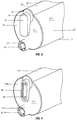
FIG. 3 is an isometric view showing the bottom of the dual syringe. -
FIG. 4 is an isometric view showing the bottom of the dual syringe with the transfer covering removed. -
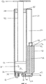
FIG. 5 is a cross section of the side profile of the harvesting syringe. -
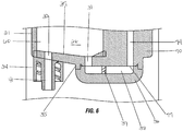
FIG. 6 is a close-up cross section of the side profile of the lower end of the harvesting syringe. -
FIG. 7 is a profile view of the needle hub assembly. -
FIG. 8 is a profile view of the cannula. -
FIG. 9 is a profile view of the percutaneous cannula. -
FIG. 10 is a close-up cross section of the side profile of the needle hub assembly. -
FIG. 11 is an isometric view of the dual syringe with a standard hypodermic needle. -
FIG. 12 is an isometric view of the dual syringe with the percutaneous cannula assembly. -
FIG. 13 is an isometric view of the dual syringe with the cannula. -
FIG. 14 is an isometric view of the transfer syringe with a standard hypodermic needle. -
FIG. 15 is a flow chart of the method of autologous stem cell transplant. - As seen in
FIGS. 1 through 6 and12 , thedual syringe 1 comprises aharvesting syringe 10 and atransfer syringe 100. Theharvesting syringe 10 comprises abarrel 20,spacer 70, and harvestingplunger 90. Thebarrel 20 comprises a partiallycylindrical sidewall 21 andbottom wall 30 that define an interior cavity 60. Theside wall 21 is shaped so that it forms a hemi-cylindrical groove 22 that extends from the top end 23 of theharvesting syringe 10 to the bottom end 24. The preferred embodiment of the groove is hemi-cylindrical but other shapes such as triangular or rectangular are envisioned. On the opposing end of thebarrel 20 from thebottom wall 30 is an opening 40.Handles 25 extend perpendicularly from thecylindrical sidewall 21 and away from the opening 40 at the top end 23 of thebarrel 20. Thehandles 25 are positioned 90 degrees from the hemi-cylindrical groove 22. - The
interior surface 26 is of thecylindrical sidewall 21 is generally smooth and corresponds in shape to theexterior surface 27 which includes the hemi-cylindrical groove 22. A ridge 28 is located along theinterior surface 26 of thecylindrical sidewall 21 near the top end 23. Thecylindrical sidewall 21 is generally translucent and contains identifyingmarkings 29 to indicate the volume of material within the interior cavity 60. - Still referring to
FIGS 1 through 6 and12 , a tubularshaped spacer 70 having a cylindrical sidewall 71, abottom wall 72, andtop wall 73 is positioned within the hemi-cylindrical groove 22 such that thebottom wall 72 of thespacer 70 andbottom wall 30 of theharvesting syringe 10 are aligned. Thetop wall 73 of thespacer 70 is positioned approximately at the midpoint of the hemi-cylindrical groove 22 of theharvesting syringe 10. Aninterior channel 74 extends from thetop wall 73 to thebottom wall 72 of the spacer 70Atop port 75 is positioned on thetop wall 73 which creates a fluid pathway withchannel 74. A syringe locking mechanism 76 having achannel 78 through its center is positioned on thetop wall 73 above thetop port 75. The syringe locking mechanism 76 may be female luer taper connection. Abottom port 77 is positioned on thebottom wall 72. A fluid pathway exists from the bottom port 76, through thechannel 74, through thetop port 75 and through thechannel 78 of the syringe locking mechanism 76. Thespacer 70 may be bonded, glued, or welded onto thebarrel 20. Alternatively, thespacer 70 andbarrel 21 may be integral. - The
harvesting syringe 10 has anoutflow port 31 positioned approximately in the middle of the of thebottom wall 30 and aninflow port 32 positioned in a portion of thebottom wall 30 opposite from thespacer 70 and aligned with thebottom port 77 and theoutflow port 31. Both theinflow port 31 andoutflow port 31 create a fluid pathway into the interior cavity 60 of thebarrel 20. Aneedle attachment 34, positioned on theexterior surface 33 of thebottom wall 30, has achannel 41 through its center such that a fluid pathway exists with theinflow port 32. Theneedle attachment 34 may be a male luer taper connection. On theexterior surface 33 of the bottom wall 30 atransfer wall 35 is formed around theoutflow port 31 and transferport 77. Atransfer cover 36 is attached to thetransfer wall 35 and covers theoutflow port 31 and transferport 77. Thetransfer wall 35 and transfer cover 36 create apathway 38 between theoutflow port 31 and transferport 77. - As seen in
FIGS. 5 and6 , theinterior surface 37 of thebottom wall 30 is sloped such that theinterior surface 37 is shaped to funnel contents into theoutflow port 31. Theexterior surface 33 of thebottom wall 30 corresponds to the same slope of theinterior surface 37. Thepathway 38 may be selectively closed by avalve 39. - The
harvesting plunger 90 has a stopper orharvesting plunger head 91 connected to one end of ashaft 92. The opposing end of theshaft 92 has a handle 93which is shaped to generally correspond with theinterior surface 26 of thecylindrical sidewall 31, including the hemi-cylindrical groove 22. Theharvesting plunger head 91 is shaped to correspond with theinterior surface 26 of thecylindrical sidewall 31 including the hemi-cylindrical groove 22. Theshaft 92 is screwed into theplunger head 91 and the friction created by theplunger head 91 and theinterior surface 26 generally holds theplunger head 91 in place which allows theshaft 92 to be screwed in or out. Theharvesting plunger head 91 is made of a malleable material such as a hard rubber to create a seal between the interior cavity 60 of thebarrel 20 and the atmospheric environment existing above theplunger head 91. The ridge 28 on theinterior surface 26 inhibits removal of theharvesting plunger head 91 from the interior cavity 60 of thebarrel 20. - As seen in
FIG. 12 , thetransfer syringe 100 comprises abarrel 101 and atransfer plunger 110. Thebarrel 101 is translucent and contains identifyingmarkings 102 to indicate the volume of material within thebarrel 101. Thetransfer syringe barrel 101 comprises acylindrical sidewall 103 having an opentop end 104 and a closedbottom end 105. Ahandle 106 extends from thebarrel 101 at itstop end 104. Aport 107 is positioned in thebottom end 105 of thesyringe barrel 101 to allow access into theinterior cavity 108 of thebarrel 101. Aneedle attachment 109 having a channel through its center is affixed to exterior surface of thebottom end 105. Theneedle attachment 109 may be a male luer taper connection. A fluid pathway exists between the channel of theneedle attachment 109,port 107, andinterior cavity 108. - As seen in
FIGS. 9 and12 , thepercutaneous cannula assembly 200 is composed of aneedle hub 210, aneedle 201, and aremovable cannula 250. As seen inFIGS. 7 and10 , the hollowtubular needle 201 is comprised ofcylindrical sidewall 202 having abeveled point 203 on one end and anopening 204 on the opposing end. Acavity 205 is formed by thecylindrical sidewall 202 and extends from thebeveled point 203 to theopening 204. - As seen in
FIGS. 7, 9 ,10 , and12 , theneedle hub 210 contains asyringe connecting portion 211 and acannula connecting portion 230. Thesyringe connecting portion 211 consists of acylindrical sidewall 212 having a connectingoutlet 213 on one end and aneedle receiving outlet 214 on the opposing end. A radial flange 217 is positioned around the connectingoutlet 213 on the exterior face 216 of thecylindrical sidewall 212. The radial flange 217 may be consistent with a female luer taper connection. A cavity 215 is formed by thecylindrical sidewall 212 and extends from the connectingoutlet 213 on one end and aneedle receiving outlet 214.. Theneedle 201 is permanently affixed to at least a portion of the interior face of thecylindrical sidewall 212. Twowings 218 extend radially away from the exterior face 216 of thecylindrical sidewall 212. Thewings 218 permit a user to grip and rotate theneedle hub 210. Thewings 218 are positioned on the exterior face 216 of thecylindrical sidewall 212 at a sufficient distance away from the radial flange 217 to allow the radial flange 217 to connect to theneedle attachment 34 and be screwed or positioned into place. A fluid communication pathway exists from the connectingoutlet 213 to thebeveled point 203 of theneedle 201. - As seen in
FIG. 8 , thecannula connecting portion 230 consists of acylindrical sidewall 231 having a connectingend 232 on one end and a cannula receiving end 233 on the opposing end. The diameter of thecylindrical sidewall 231 of thecannula connecting portion 230 is greater than thecylindrical sidewall 212 of thesyringe connecting portion 211. The connectingend 232 is attached to the exterior face 216 of thecylindrical sidewall 212 of thesyringe connecting portion 211 at the approximate midpoint of thecylindrical sidewall 212 of thesyringe connecting portion 211.Threads 234 are positioned on theinterior face 234 of thecylindrical sidewall 231 of thecannula connecting portion 230.Threads 234 may be consistent with a male luer lock taper connection.Radial ridges 236 are positioned on the external face 237 of thecylindrical sidewall 231 of thecannula connecting portion 230. Theradial ridges 236 assist in gripping theneedle hub 210. - The distance between the
interior face 234 of thecylindrical sidewall 231 of thecannula connecting portion 230 and the exterior face 216 of thecylindrical sidewall 212 of thesyringe connecting portion 211 is of sufficient distance that a cannula or other syringe may be removably attached to theneedle hub 210. - As seen in
FIG. 8 , thecannula 250 is comprised of atubular shaft 251 attached to acannula hub 252. Thecannula hub 252 is tubular in shape with a generally cylindrical sidewall 253 with a cannula receiving portion 254 on one end andoutlet 255 on the opposing end. A radial flange 256 is positioned around theoutlet 255 of the cylindrical sidewall 253. The radial flange 256 may be consistent with a female luer taper connection. One end of thetubular shaft 251 is attached to thecannula hub 252 at the cannula receiving portion 254. The other end of thetubular shaft 251 is atapered outlet 258. The cylindrical sidewall 253 andcannula shaft 251 form a cavity 257 between theoutlet 255 and the taperedoutlet 258. Thecannula shaft 251 and the taperedoutlet 258 have an inner diameter large enough to allow theneedle 201 to pass through. Ports 259 extend longitudinally through the sidewall of thetubular shaft 251. Ports 259 may have smooth edges for minimal tissue cleavage or sharp skived edges for maximum tissue recovery depending on the desired use and desired tissue and/or cells to harvest. Ports 259 may be oriented on one side or may extend generally around the circumference of thetubular shaft 251. Depth markings 260 are positioned along the outer face of thecannula shaft 251 that indicate the distance from the respective marking to the taperedoutlet 258. - As seen in
FIGS. 11 through 14 , thetransfer syringe 100 is attached to theharvesting syringe 10 through attachment of theneedle attachment 109 to the syringe locking mechanism 76 of thespacer 70. Thebarrel 101 of thetransfer syringe 100 partially fits within the hemi-cylindrical groove 22 of theharvesting syringe 10. Theharvesting plunger head 91 is shaped to not interfere with thetransfer syringe 100 or to prohibit the screwing in of thetransfer syringe 100 onto the syringe locking mechanism 76. A pathway is created between the interior cavity 60 of theharvesting syringe 10 and theinterior cavity 108 of thetransfer syringe 100 by theoutflow port 31,pathway 38,bottom port 77,interior cavity 74 of thespacer 70,top port 75,needle attachment 109, andport 107. Thepathway 38 may be selectively closed by avalve 39.Valve 39 may designed as a pressure sensitive valve which seals with positive pressure fromoutflow port 31 but opens upon negative pressure from thebottom port 77. - As seen in
FIG. 12 , theneedle hub 210 may attach to thedual syringe 1 through mating ofneedle attachment 34 of thedual syringe 1 and ridge 217 of theneedle hub assembly 210. Thecannula 250 may attach to theneedle hub 210 through mating of thecannula connecting portion 230 and radial flange 256 of thecannula 250. As seen inFIG. 9 and12 , theneedle 201 extends out the taperedoutlet 258 of thecannula 250 when thecannula 250 is attached to theneedle hub 210. As seen inFIG. 13 , thecannula 250 may also attach to thedual syringe 1 through mating ofneedle attachment 34 of thedual syringe 1 and radial flange 256 of thecannula 250. In the preferred embodiment, the attachments are luer lock taper connections although alternative embodiments may use a luer slip taper connection. - Referring to
FIG. 15 , thebroad process 300 of operation of thedual syringe 1 comprises the following steps: - Anesthetize the patient generally or locally where cells are to be harvested. Anesthetization may occur through use of the
dual syringe 1 with a standardhypodermic needle 50 attached as seen inFIG. 11 , or through the percutaneousadipose aspirating cannula 200 as seen inFIG. 12 . Anesthetizing agent is drawn into theharvesting syringe 10 by pulling on theharvesting plunger 90. The anesthetizing agent is drawn through the standardhypodermic needle 50 or percutaneousadipose aspirating cannula 200. The anesthetic agent is then applied locally at the site of cell harvesting. - The
dual syringe 1, with the attached transfer syringe 100 (with thetransfer plunger 110 fully depressed) and thepercutaneous cannula assembly 200, is inserted into tissue or bone of a patient to harvest the desired cells. Thebeveled point 203 of theneedle 201 along with thecannula 250 inserts percutaneously through patient's skin and advanced into the patient until the appropriate depth as indicated by the depth markings 260 on thecannula 250. The taperedoutlet 255 of thecannula 250 assists insertion into the patient's skin to reduce any catching or blunt trauma. - Once the desired depth is obtained, the
cannula 250 is unmated from theneedle hub assembly 210 which allows for the removal of the dual syringe 1 (with theneedle hub assembly 210 still attached) from thecannula 250. Theneedle hub assembly 210 is unmated from theharvesting syringe 10. The harvesting syringe is then attached to thecannula 250 through mating theneedle attachment 34 of thedual syringe 1 and ridge 256 of thecannula 250. This establishes a fluid communication pathway from the taperedoutlet 258 and ports 259, through thetubular shaft 251, through thecannula hub 252, through theoutlet 255, through theinflow port 32, and into thebarrel 20 of theharvesting syringe 10. - The
cannula 250 may then be used as a standard aspirating cannula to harvest the desired cells. The user creates negative pressure withinbarrel 20 by pulling on theharvesting plunger 90 to draw in cells and tissues while simultaneously moving the cannula within the patient's body at the desired location. As thecannula 250 is moved back and forth while inside the patient, the ports 259 and taperedoutlet 258 shear and collect cells/tissue which are then drawn into thecannula 250 and are ultimately drawn into thebarrel 20. - Once the desired volume of cells and/or tissues are harvested, the harvesting syringe 10 (with the
cannula 250 still attached) is removed from the patient. - The
cannula 250 is removed 270 from theharvesting syringe 10. Theshaft 92 is unscrewed from theplunger head 91 and removed from theharvesting syringe 10. A standard syringe port cap is attached to theneedle attachment 34 to sealinflow port 32. The cap ensures sterility and prevents migration of the cell pellet into theinflow port 32. - The
dual syringe 1 is placed in a centrifuge and spun at approximately 500 to 2000 g forces for a period of 3 to 20 minutes. Centrifugation causes the aspirated cells to separate from the aspirated fluid. As a result of the funnel shape of thebottom wall 30, the cells, denser than the fluid, form a pellet on thebottom wall 30 near theoutflow port 31. Thevalve 39 remains closed due to the positive pressure exerted from theoutflow port 31 which prevents any of the contents of the barrel from migrating throughpathway 38 and/or through thebottom port 77 of thespacer 70. - The
dual syringe 1 is removed from the centrifuge. Thetransfer plunger 110 is pulled away from thebottom end 105 which creates negative pressure within theinterior cavity 108 of thetransfer syringe 100. This negative pressure opens thevalve 39 to allow cells of the pellet to move through theoutflow port 31, through thepathway 38, through theinterior cavity 74 of thespacer 70, through thetop port 75, through theport 107 of the transfer syringe and into theinterior cavity 108 of thetransfer syringe 100. To adjust for the varying hydraulic pressure within the interior cavity 60 of theharvesting syringe 10, if necessary, the harvesting plunger may be manually depressed, after reattachment of theshaft 92, by the user in conjunction with user's pulling of thetransfer plunger 110. - Once the cell pellet is fully transferred to the
transfer syringe 100, thetransfer syringe 100 is removed from the syringe locking mechanism 76 and a standard hypodermic needle is attached to thetransfer syringe 100 at theneedle attachment 109 as seen inFIG. 14 . The gauge and design of the needle for the transfer syringe may depend on the type of tissue delivered, the tissue the needle needs to penetrate to deliver the cells and the volume of the cells to be delivered. Saline and/or other chemicals may be added to reconstitute the cell pellet in thetransfer syringe 100. - The
transfer syringe 100 is then inserted into a patient in a specific location for delivery of the harvested cells for therapeutic purposes. - A person of ordinary skill in the art would appreciate the number, gauge, and design of the ports 259 may vary depending on the type of tissue harvested, the tissue the needle needs to penetrate to acquire the tissue, and the volume of the tissue needed.
- The dual syringe may be used with a standard aspirating cannula as well with traditional access to the cells created through trocar use or surgical incision. Once the cells are harvested, the dual syringe is removed from the patient. The standard aspirating cannula is removed 270 from the
harvesting syringe 10. Theshaft 92 is unscrewed from theplunger head 91 and removed from theharvesting syringe 10.. A standard syringe port cap is attached to theneedle attachment 34 to sealinflow port 32. Thedual syringe 1 is placed in a centrifuge and spun at approximately 500 to 2000 g forces for a period of 3 to 20 minutes. Centrifugation causes the aspirated cells to separate from the aspirated fluid. As a result of the funnel shape of thebottom wall 30, the cells, denser than the fluid, form a pellet on thebottom wall 30 near theoutflow port 31. Thevalve 39 remains closed due to the positive pressure exerted from theoutflow port 31 which prevents any of the contents of the barrel from migrating throughpathway 38 and/or through thebottom port 77 of thespacer 70. Thedual syringe 1 is removed from the centrifuge. Thetransfer plunger 110 is pulled away from thebottom end 105 which creates negative pressure within theinterior cavity 108 of thetransfer syringe 100. This negative pressure opens thevalve 39 to allow cells of the pellet to move through theoutflow port 31, through thepathway 38, through theinterior cavity 74 of thespacer 70, through thetop port 75, through theport 107 of the transfer syringe and into theinterior cavity 108 of thetransfer syringe 100. To adjust for the varying hydraulic pressure within the interior cavity 60 of theharvesting syringe 10, if necessary, the harvesting plunger may be manually depressed, after reattachment of theshaft 92, by the user in conjunction with user's pulling of thetransfer plunger 110. Once the cell pellet is fully transferred to thetransfer syringe 100, thetransfer syringe 100 is removed from the syringe locking mechanism 76 and a standard hypodermic needle is attached to thetransfer syringe 100 at theneedle attachment 109 as seen inFIG. 14 . The gauge and design of the needle for the transfer syringe may depend on the type of tissue delivered, the tissue the needle needs to penetrate to deliver the cells and the volume of the cells to be delivered. Saline and/or other chemicals may be added to reconstitute the cell pellet in thetransfer syringe 100. Thetransfer syringe 100 is then inserted into a patient in a specific location for delivery of the harvested cells for therapeutic purposes. - The above device may be used for autologous stem cell transplantation in an office setting as described in
FIG. 15 . A healthcare provider may utilize local anesthetic at the specific harvesting site or general anesthetic for the harvesting of stem cells. Stem cell harvesting may occur through adipose tissue in a patient's abdominal region, or through adipose tissue in another adipose-rich region such as the inner thigh or through a patient's bone marrow. The healthcare provider utilizes the sterile dual syringe and attaches thepercutaneous cannula 200. The healthcare provider inserts thedual syringe 1 with thepercutaneous cannula 200 as described inFIG. 15 into the patient's abdomen andaspirates 50 to 60 milliliters of adipose tissue into theharvesting syringe 10. Centrifugation separates a cellular pellet rich in mesenchymal stem cells from the stromal vascular fraction. The mesenchymal stem cells are then transferred to thetransfer syringe 100 as described inFIG. 15 . The transfer syringe is removed from the harvesting syringe, a needle is attached as shown inFIG. 11 , and then the mesenchymal stem cells are transplanted into the same patient for treatment of osteoarthritis, for assistance in wound healing, or for one or more of many other regenerative medicine uses. The procedure is accomplished in the same office visit for the patient. - In a preferred embodiment the
harvesting syringe 10,transfer syringe 100,percutaneous cannula assembly 200, syringe port cap, andhypodermic needle 50 are sterile and stored in a single use sterile packaging kit. The packaged unit is designed for singular use for a single patient for transplantation of autologous tissue.
Claims (21)
- A dual syringe assembly (1) comprising
a first syringe (10) having a sidewall (21) and bottom wall (30) that define a cavity (60) having an open end (40) opposite said bottom wall (30);
a first port (32) and a second port (31) in said bottom wall (30) each of said ports (31, 32) creating a fluid pathway with said cavity (60);
a plunger (90) inserted into said cavity of said first syringe (10) through said open end (40);
a second syringe (100) having a sidewall (103) and bottom wall (105) that define a cavity (108) having an open end (104) opposite said bottom wall (105);
a port (107) in said bottom wall (105) of said second syringe (100) creating a fluid pathway with said cavity (108) of said second syringe (100); and
a plunger (110) inserted into said cavity (108) of said second syringe (100) through said open end (104);
wherein said second port (31) of said first syringe (10) is fluidly connected to said port (107) of said second syringe (100);
wherein said sidewall (21) of said first syringe (10) is shaped to form a groove (22); and
wherein at least a portion of said second syringe (100) is positioned within said groove (22) of said sidewall (21) of said first syringe (10). - A dual syringe assembly of claim 1 wherein said groove (22) extends along at least a portion of the length of said sidewall (21).
- A dual syringe assembly (1) of claim 1 wherein:said groove (22) extends from a first end (23, 24) to a second end (23, 24) of said first syringe (10); andsaid groove (22) is hemi-cylindrical.
- A dual syringe assembly (1) of claim 1 further comprising:a spacer (70) positioned in said groove (22) wherein said spacer (70) has a first end with a first port (77) and a second end with a second port (75);a channel (74) disposed between said first and second ports (77, 75) wherein said first port (77) of said spacer (70) is fluidly connected with said second port (31) of said first syringe (10) and said second port (75) of said spacer (70) is fluidly connected with said port (107) of said second syringe (100); andwherein said second syringe (100) is attached to said second end of said spacer (70).
- A dual syringe assembly (1) of claim 4 wherein said first end of said spacer (70) is aligned with said bottom wall (30) of said first syringe (10).
- A dual syringe assembly of claim 1 wherein:
said bottom wall (105) of said first syringe (10) has an interior face that is sloped from said first port (32) to said second port (31). - A dual syringe assembly (1) of claim 1 further comprising a valve (39) disposed between said second port (31) of said first syringe (10) and said port (107) of said second syringe (100).
- A dual syringe assembly (1) of claim 4 further comprising a valve (39) disposed between said second port (31) of said first syringe (10) and said first port (77) of said spacer (70).
- A dual syringe assembly (1) of claim 1 wherein said plunger (90) of said first syringe (10) comprises a shaft (92) with a plunger head (91) on one end and a handle (93) on the opposing end wherein said shaft (92) is removable from said plunger head (91);
optionally wherein said plunger head (91) is shaped to correspond to the shape of the interior surface (26) of said sidewall (21) of said first syringe (10). - A dual syringe assembly (1) of claim 1 further comprising:a needle hub (210) comprising a syringe attachment member (211), cannula attachment member (230), and a hollow needle (201) extending from said cannula attachment member (230); anda cannula (250) having an opening (258) on one end and an attachment member (256) on the opposing end wherein said attachment member (256) of said cannula (250) is connected to said cannula attachment member (230) of said needle hub (210); and said needle (201) of said needle hub (210) is positioned within said cannula (250) and extends through said opening (258) of said cannula (250);wherein said syringe attachment member (211) of said needle hub (210) is attached to said first syringe (10); andsaid cannula (250) is removable from said needle hub (210); orsaid cannula (250) is attachable to and detachable from said first syringe (10).
- A dual syringe (1) assembly of claim 10 wherein said hollow needle (201) is fluidly connected with said first port (32) of said first syringe (10).
- A dual syringe assembly (1) of claim 10 wherein said cannula (250) further comprises at least one port (259) along the longitudinal axis.
- A dual syringe assembly (1) of clam 10 wherein said cannula (250) tapers to said opening (258) of said cannula (250).
- A dual syringe assembly (1) of claim 10 wherein needle hub (210) is attachable to and detachable from said first syringe (10).
- A dual syringe assembly (1) of claim 1 further comprising:a cannula (250) having an opening (258) on one end and an attachment member (256) on the opposing end wherein said attachment member (256) of said cannula is attachable to and detachable from said first syringe (10); andwherein said cannula (250) is fluidly connected to said first port (32) of said first syringe (10).
- A dual syringe assembly (1) of claim 15 wherein said cannula (250) further comprises at least one port (259) along the longitudinal axis.
- A dual syringe assembly (1) of claim 15 wherein said cannula (250) tapers to said opening (258) of said cannula (250).
- A combination of a dual syringe assembly (1) according to claim 1 and a percutaneous cannula assembly (200) comprising:a needle hub (210) comprising a syringe attachment member (211), cannula attachment member (230), and a hollow needle (201) extending from said cannula attachment member (230); anda cannula (250) having an opening (258) on one end and an attachment member (256) on the opposing end wherein said attachment member (256) of said cannula (250) is connected to said cannula attachment member (211) of said needle hub (210);said needle (201) of said needle hub (210) is positioned within said cannula (250) and extends through said opening (258) of said cannula (250); andwherein said syringe attachment member (211) of said needle hub (210) is attachable to said syringe assembly (1).
- A combination of claim 18 wherein said cannula (250) is removable from said needle hub (210).
- A combination of claim 18 wherein said needle (201) is fluidly connected to said syringe assembly (1).
- A combination of claim 18 wherein said cannula (250) further comprises at least one port (259) along the longitudinal axis; or
said cannula (250) tapers to said opening (258).
Applications Claiming Priority (3)
| Application Number | Priority Date | Filing Date | Title |
|---|---|---|---|
| US201462022511P | 2014-07-09 | 2014-07-09 | |
| US201462092022P | 2014-12-15 | 2014-12-15 | |
| PCT/US2015/039833 WO2016007800A1 (en) | 2014-07-09 | 2015-07-09 | Dual syringe with percutaneous cannula |
Publications (3)
| Publication Number | Publication Date |
|---|---|
| EP3166664A1 EP3166664A1 (en) | 2017-05-17 |
| EP3166664A4 EP3166664A4 (en) | 2018-06-20 |
| EP3166664B1 true EP3166664B1 (en) | 2020-05-20 |
Family
ID=55064929
Family Applications (1)
| Application Number | Title | Priority Date | Filing Date |
|---|---|---|---|
| EP15818817.7A Active EP3166664B1 (en) | 2014-07-09 | 2015-07-09 | Dual syringe with percutaneous cannula |
Country Status (3)
| Country | Link |
|---|---|
| US (1) | US20170224318A1 (en) |
| EP (1) | EP3166664B1 (en) |
| WO (1) | WO2016007800A1 (en) |
Cited By (1)
| Publication number | Priority date | Publication date | Assignee | Title |
|---|---|---|---|---|
| DE102024103900A1 (en) * | 2024-02-12 | 2025-08-14 | GEOMAR Helmholtz-Zentrum für Ozeanforschung Kiel, Stiftung des öffentlichen Rechts | COMBINED SYRINGE-PLUNGER DEVICE AND USE |
Families Citing this family (3)
| Publication number | Priority date | Publication date | Assignee | Title |
|---|---|---|---|---|
| CH711240A2 (en) | 2015-06-23 | 2016-12-30 | Tecpharma Licensing Ag | Auto injection device. |
| CN108310543B (en) * | 2018-03-07 | 2020-08-04 | 庄国燕 | A syringe capable of controlling the flow rate of push liquid |
| US11340104B2 (en) | 2020-07-07 | 2022-05-24 | Matthew Moers | Syringe with a valve in a housing for measuring chemicals |
Family Cites Families (12)
| Publication number | Priority date | Publication date | Assignee | Title |
|---|---|---|---|---|
| US3094122A (en) * | 1961-01-18 | 1963-06-18 | Theophile E Gauthier | Flexible cannula and intravenous needle combined |
| US3978846A (en) * | 1975-01-02 | 1976-09-07 | Bailey Donald L | Syringe for taking blood samples |
| US4253501A (en) * | 1979-11-09 | 1981-03-03 | Ims Limited | Transfer system |
| US5199949A (en) * | 1991-03-08 | 1993-04-06 | Habley Medical Technology Corp. | Multiple pharmaceutical syringe |
| US20060097013A1 (en) * | 2003-04-28 | 2006-05-11 | Bargh Adrian N | Dispenser |
| CN101175517A (en) * | 2005-05-16 | 2008-05-07 | 马林克罗特公司 | Multi-barrel syringe with integrated tubing |
| US7892210B2 (en) * | 2005-10-03 | 2011-02-22 | Baxa Corporation | Apparatus, method and system for administration of IV liquid medication and IV flush solutions |
| US20090198211A1 (en) * | 2008-02-06 | 2009-08-06 | Intravena, Llc | Convenience IV kits and methods of use |
| US8152778B2 (en) * | 2008-09-30 | 2012-04-10 | Tyco Healthcare Group Lp | Device for interfacing with standard luer lock syringes |
| US20110118659A1 (en) * | 2009-11-13 | 2011-05-19 | Armand Maaskamp | Multi-port syringe assembly |
| EP2776089A4 (en) * | 2011-11-08 | 2015-03-18 | David R Duncan | Compact non-electric medicament infuser |
| US9340346B2 (en) * | 2013-11-21 | 2016-05-17 | Smarthealth, Inc. | Precision dispensing device of small volume from pre-filled syringes |
-
2015
- 2015-07-09 EP EP15818817.7A patent/EP3166664B1/en active Active
- 2015-07-09 WO PCT/US2015/039833 patent/WO2016007800A1/en not_active Ceased
- 2015-07-09 US US15/502,814 patent/US20170224318A1/en not_active Abandoned
Non-Patent Citations (1)
| Title |
|---|
| None * |
Cited By (1)
| Publication number | Priority date | Publication date | Assignee | Title |
|---|---|---|---|---|
| DE102024103900A1 (en) * | 2024-02-12 | 2025-08-14 | GEOMAR Helmholtz-Zentrum für Ozeanforschung Kiel, Stiftung des öffentlichen Rechts | COMBINED SYRINGE-PLUNGER DEVICE AND USE |
Also Published As
| Publication number | Publication date |
|---|---|
| EP3166664A4 (en) | 2018-06-20 |
| US20170224318A1 (en) | 2017-08-10 |
| WO2016007800A1 (en) | 2016-01-14 |
| EP3166664A1 (en) | 2017-05-17 |
Similar Documents
| Publication | Publication Date | Title |
|---|---|---|
| US20200397991A1 (en) | Dual Syringe Assembly | |
| TWI586394B (en) | Device for extracting, storing and/or processing blood or other substances of human or animal origin, and for applying blood compounds or other biological compounds | |
| US5352205A (en) | Bloodless insertion catheter assembly | |
| US20250144286A1 (en) | Transcutaneous device for removal of fluid from a body | |
| ES2832754T3 (en) | Container device for the collection, storage and processing of blood or a blood compound | |
| JP2002511007A (en) | Intravenous catheter guiding method and device | |
| US11504456B2 (en) | Percutaneous drainage device | |
| US10286140B2 (en) | Centrifuge apparatus for separating blood components | |
| US20170224318A1 (en) | Dual Syringe with Percutaneous Cannula | |
| AU2023200273B2 (en) | Vascular access device adapter | |
| JP2023123767A (en) | Methods and kits for preservation of adipose tissue grafts | |
| US9770425B2 (en) | Implantable bone marrow access apparatus | |
| US10349924B2 (en) | Percutaneous aspirating cannula | |
| US20220296222A1 (en) | Dual Syringe for Use with Percutaneous Aspirating Cannula | |
| US12134092B2 (en) | Apparatus and method for centrifuging a biologic | |
| CN209422595U (en) | Detachable piston type acquisition separation injecting medicinal platelet rich plasma preparation facilities | |
| CN216703068U (en) | A combined and detachable platelet-rich plasma preparation device | |
| WO2023172543A1 (en) | Dual syringe for use with percutaneous aspirating cannula | |
| CN204133478U (en) | Clinical laboratory's blood taking tube | |
| BR112023000697B1 (en) | DEVICE, KIT AND METHODS FOR CREATING PLATELET-RICH PLASMA | |
| US20030158513A1 (en) | Cylindrical assembly for harvesting tissue | |
| CN208943061U (en) | A kind of Anti-stabbing infusion apparatus | |
| CN207384274U (en) | Bone marrow collection device | |
| AU2013391895A1 (en) | Disposable periphery cannula infusion device |
Legal Events
| Date | Code | Title | Description |
|---|---|---|---|
| STAA | Information on the status of an ep patent application or granted ep patent |
Free format text: STATUS: THE INTERNATIONAL PUBLICATION HAS BEEN MADE |
|
| PUAI | Public reference made under article 153(3) epc to a published international application that has entered the european phase |
Free format text: ORIGINAL CODE: 0009012 |
|
| STAA | Information on the status of an ep patent application or granted ep patent |
Free format text: STATUS: REQUEST FOR EXAMINATION WAS MADE |
|
| 17P | Request for examination filed |
Effective date: 20170207 |
|
| AK | Designated contracting states |
Kind code of ref document: A1 Designated state(s): AL AT BE BG CH CY CZ DE DK EE ES FI FR GB GR HR HU IE IS IT LI LT LU LV MC MK MT NL NO PL PT RO RS SE SI SK SM TR |
|
| AX | Request for extension of the european patent |
Extension state: BA ME |
|
| DAV | Request for validation of the european patent (deleted) | ||
| DAX | Request for extension of the european patent (deleted) | ||
| RIC1 | Information provided on ipc code assigned before grant |
Ipc: A61M 5/19 20060101AFI20180131BHEP Ipc: A61B 10/02 20060101ALI20180131BHEP |
|
| A4 | Supplementary search report drawn up and despatched |
Effective date: 20180523 |
|
| RIC1 | Information provided on ipc code assigned before grant |
Ipc: A61B 10/02 20060101ALI20180516BHEP Ipc: A61M 5/19 20060101AFI20180516BHEP |
|
| REG | Reference to a national code |
Ref country code: DE Ref legal event code: R079 Ref document number: 602015053117 Country of ref document: DE Free format text: PREVIOUS MAIN CLASS: A61M0005190000 Ipc: A61M0005320000 |
|
| GRAP | Despatch of communication of intention to grant a patent |
Free format text: ORIGINAL CODE: EPIDOSNIGR1 |
|
| STAA | Information on the status of an ep patent application or granted ep patent |
Free format text: STATUS: GRANT OF PATENT IS INTENDED |
|
| RIC1 | Information provided on ipc code assigned before grant |
Ipc: A61M 5/19 20060101ALI20190524BHEP Ipc: A61B 10/02 20060101ALI20190524BHEP Ipc: A61M 5/32 20060101AFI20190524BHEP |
|
| INTG | Intention to grant announced |
Effective date: 20190627 |
|
| GRAS | Grant fee paid |
Free format text: ORIGINAL CODE: EPIDOSNIGR3 |
|
| GRAA | (expected) grant |
Free format text: ORIGINAL CODE: 0009210 |
|
| STAA | Information on the status of an ep patent application or granted ep patent |
Free format text: STATUS: THE PATENT HAS BEEN GRANTED |
|
| AK | Designated contracting states |
Kind code of ref document: B1 Designated state(s): AL AT BE BG CH CY CZ DE DK EE ES FI FR GB GR HR HU IE IS IT LI LT LU LV MC MK MT NL NO PL PT RO RS SE SI SK SM TR |
|
| REG | Reference to a national code |
Ref country code: GB Ref legal event code: FG4D |
|
| REG | Reference to a national code |
Ref country code: CH Ref legal event code: EP |
|
| REG | Reference to a national code |
Ref country code: DE Ref legal event code: R096 Ref document number: 602015053117 Country of ref document: DE |
|
| REG | Reference to a national code |
Ref country code: AT Ref legal event code: REF Ref document number: 1272198 Country of ref document: AT Kind code of ref document: T Effective date: 20200615 |
|
| REG | Reference to a national code |
Ref country code: LT Ref legal event code: MG4D |
|
| REG | Reference to a national code |
Ref country code: NL Ref legal event code: MP Effective date: 20200520 |
|
| PG25 | Lapsed in a contracting state [announced via postgrant information from national office to epo] |
Ref country code: GR Free format text: LAPSE BECAUSE OF FAILURE TO SUBMIT A TRANSLATION OF THE DESCRIPTION OR TO PAY THE FEE WITHIN THE PRESCRIBED TIME-LIMIT Effective date: 20200821 Ref country code: FI Free format text: LAPSE BECAUSE OF FAILURE TO SUBMIT A TRANSLATION OF THE DESCRIPTION OR TO PAY THE FEE WITHIN THE PRESCRIBED TIME-LIMIT Effective date: 20200520 Ref country code: LT Free format text: LAPSE BECAUSE OF FAILURE TO SUBMIT A TRANSLATION OF THE DESCRIPTION OR TO PAY THE FEE WITHIN THE PRESCRIBED TIME-LIMIT Effective date: 20200520 Ref country code: PT Free format text: LAPSE BECAUSE OF FAILURE TO SUBMIT A TRANSLATION OF THE DESCRIPTION OR TO PAY THE FEE WITHIN THE PRESCRIBED TIME-LIMIT Effective date: 20200921 Ref country code: IS Free format text: LAPSE BECAUSE OF FAILURE TO SUBMIT A TRANSLATION OF THE DESCRIPTION OR TO PAY THE FEE WITHIN THE PRESCRIBED TIME-LIMIT Effective date: 20200920 Ref country code: SE Free format text: LAPSE BECAUSE OF FAILURE TO SUBMIT A TRANSLATION OF THE DESCRIPTION OR TO PAY THE FEE WITHIN THE PRESCRIBED TIME-LIMIT Effective date: 20200520 Ref country code: NO Free format text: LAPSE BECAUSE OF FAILURE TO SUBMIT A TRANSLATION OF THE DESCRIPTION OR TO PAY THE FEE WITHIN THE PRESCRIBED TIME-LIMIT Effective date: 20200820 |
|
| PG25 | Lapsed in a contracting state [announced via postgrant information from national office to epo] |
Ref country code: HR Free format text: LAPSE BECAUSE OF FAILURE TO SUBMIT A TRANSLATION OF THE DESCRIPTION OR TO PAY THE FEE WITHIN THE PRESCRIBED TIME-LIMIT Effective date: 20200520 Ref country code: RS Free format text: LAPSE BECAUSE OF FAILURE TO SUBMIT A TRANSLATION OF THE DESCRIPTION OR TO PAY THE FEE WITHIN THE PRESCRIBED TIME-LIMIT Effective date: 20200520 Ref country code: BG Free format text: LAPSE BECAUSE OF FAILURE TO SUBMIT A TRANSLATION OF THE DESCRIPTION OR TO PAY THE FEE WITHIN THE PRESCRIBED TIME-LIMIT Effective date: 20200820 Ref country code: LV Free format text: LAPSE BECAUSE OF FAILURE TO SUBMIT A TRANSLATION OF THE DESCRIPTION OR TO PAY THE FEE WITHIN THE PRESCRIBED TIME-LIMIT Effective date: 20200520 |
|
| REG | Reference to a national code |
Ref country code: AT Ref legal event code: MK05 Ref document number: 1272198 Country of ref document: AT Kind code of ref document: T Effective date: 20200520 |
|
| PG25 | Lapsed in a contracting state [announced via postgrant information from national office to epo] |
Ref country code: AL Free format text: LAPSE BECAUSE OF FAILURE TO SUBMIT A TRANSLATION OF THE DESCRIPTION OR TO PAY THE FEE WITHIN THE PRESCRIBED TIME-LIMIT Effective date: 20200520 Ref country code: NL Free format text: LAPSE BECAUSE OF FAILURE TO SUBMIT A TRANSLATION OF THE DESCRIPTION OR TO PAY THE FEE WITHIN THE PRESCRIBED TIME-LIMIT Effective date: 20200520 |
|
| PG25 | Lapsed in a contracting state [announced via postgrant information from national office to epo] |
Ref country code: ES Free format text: LAPSE BECAUSE OF FAILURE TO SUBMIT A TRANSLATION OF THE DESCRIPTION OR TO PAY THE FEE WITHIN THE PRESCRIBED TIME-LIMIT Effective date: 20200520 Ref country code: CZ Free format text: LAPSE BECAUSE OF FAILURE TO SUBMIT A TRANSLATION OF THE DESCRIPTION OR TO PAY THE FEE WITHIN THE PRESCRIBED TIME-LIMIT Effective date: 20200520 Ref country code: AT Free format text: LAPSE BECAUSE OF FAILURE TO SUBMIT A TRANSLATION OF THE DESCRIPTION OR TO PAY THE FEE WITHIN THE PRESCRIBED TIME-LIMIT Effective date: 20200520 Ref country code: RO Free format text: LAPSE BECAUSE OF FAILURE TO SUBMIT A TRANSLATION OF THE DESCRIPTION OR TO PAY THE FEE WITHIN THE PRESCRIBED TIME-LIMIT Effective date: 20200520 Ref country code: EE Free format text: LAPSE BECAUSE OF FAILURE TO SUBMIT A TRANSLATION OF THE DESCRIPTION OR TO PAY THE FEE WITHIN THE PRESCRIBED TIME-LIMIT Effective date: 20200520 Ref country code: IT Free format text: LAPSE BECAUSE OF FAILURE TO SUBMIT A TRANSLATION OF THE DESCRIPTION OR TO PAY THE FEE WITHIN THE PRESCRIBED TIME-LIMIT Effective date: 20200520 Ref country code: SM Free format text: LAPSE BECAUSE OF FAILURE TO SUBMIT A TRANSLATION OF THE DESCRIPTION OR TO PAY THE FEE WITHIN THE PRESCRIBED TIME-LIMIT Effective date: 20200520 Ref country code: DK Free format text: LAPSE BECAUSE OF FAILURE TO SUBMIT A TRANSLATION OF THE DESCRIPTION OR TO PAY THE FEE WITHIN THE PRESCRIBED TIME-LIMIT Effective date: 20200520 |
|
| REG | Reference to a national code |
Ref country code: DE Ref legal event code: R097 Ref document number: 602015053117 Country of ref document: DE |
|
| PG25 | Lapsed in a contracting state [announced via postgrant information from national office to epo] |
Ref country code: MC Free format text: LAPSE BECAUSE OF FAILURE TO SUBMIT A TRANSLATION OF THE DESCRIPTION OR TO PAY THE FEE WITHIN THE PRESCRIBED TIME-LIMIT Effective date: 20200520 Ref country code: SK Free format text: LAPSE BECAUSE OF FAILURE TO SUBMIT A TRANSLATION OF THE DESCRIPTION OR TO PAY THE FEE WITHIN THE PRESCRIBED TIME-LIMIT Effective date: 20200520 Ref country code: PL Free format text: LAPSE BECAUSE OF FAILURE TO SUBMIT A TRANSLATION OF THE DESCRIPTION OR TO PAY THE FEE WITHIN THE PRESCRIBED TIME-LIMIT Effective date: 20200520 |
|
| REG | Reference to a national code |
Ref country code: CH Ref legal event code: PL |
|
| PLBE | No opposition filed within time limit |
Free format text: ORIGINAL CODE: 0009261 |
|
| STAA | Information on the status of an ep patent application or granted ep patent |
Free format text: STATUS: NO OPPOSITION FILED WITHIN TIME LIMIT |
|
| 26N | No opposition filed |
Effective date: 20210223 |
|
| REG | Reference to a national code |
Ref country code: BE Ref legal event code: MM Effective date: 20200731 |
|
| PG25 | Lapsed in a contracting state [announced via postgrant information from national office to epo] |
Ref country code: LI Free format text: LAPSE BECAUSE OF NON-PAYMENT OF DUE FEES Effective date: 20200731 Ref country code: LU Free format text: LAPSE BECAUSE OF NON-PAYMENT OF DUE FEES Effective date: 20200709 Ref country code: CH Free format text: LAPSE BECAUSE OF NON-PAYMENT OF DUE FEES Effective date: 20200731 |
|
| PG25 | Lapsed in a contracting state [announced via postgrant information from national office to epo] |
Ref country code: BE Free format text: LAPSE BECAUSE OF NON-PAYMENT OF DUE FEES Effective date: 20200731 Ref country code: SI Free format text: LAPSE BECAUSE OF FAILURE TO SUBMIT A TRANSLATION OF THE DESCRIPTION OR TO PAY THE FEE WITHIN THE PRESCRIBED TIME-LIMIT Effective date: 20200520 |
|
| PG25 | Lapsed in a contracting state [announced via postgrant information from national office to epo] |
Ref country code: IE Free format text: LAPSE BECAUSE OF NON-PAYMENT OF DUE FEES Effective date: 20200709 |
|
| PG25 | Lapsed in a contracting state [announced via postgrant information from national office to epo] |
Ref country code: TR Free format text: LAPSE BECAUSE OF FAILURE TO SUBMIT A TRANSLATION OF THE DESCRIPTION OR TO PAY THE FEE WITHIN THE PRESCRIBED TIME-LIMIT Effective date: 20200520 Ref country code: MT Free format text: LAPSE BECAUSE OF FAILURE TO SUBMIT A TRANSLATION OF THE DESCRIPTION OR TO PAY THE FEE WITHIN THE PRESCRIBED TIME-LIMIT Effective date: 20200520 Ref country code: CY Free format text: LAPSE BECAUSE OF FAILURE TO SUBMIT A TRANSLATION OF THE DESCRIPTION OR TO PAY THE FEE WITHIN THE PRESCRIBED TIME-LIMIT Effective date: 20200520 |
|
| PG25 | Lapsed in a contracting state [announced via postgrant information from national office to epo] |
Ref country code: MK Free format text: LAPSE BECAUSE OF FAILURE TO SUBMIT A TRANSLATION OF THE DESCRIPTION OR TO PAY THE FEE WITHIN THE PRESCRIBED TIME-LIMIT Effective date: 20200520 |
|
| PGFP | Annual fee paid to national office [announced via postgrant information from national office to epo] |
Ref country code: DE Payment date: 20250722 Year of fee payment: 11 |
|
| PGFP | Annual fee paid to national office [announced via postgrant information from national office to epo] |
Ref country code: GB Payment date: 20250722 Year of fee payment: 11 |
|
| PGFP | Annual fee paid to national office [announced via postgrant information from national office to epo] |
Ref country code: FR Payment date: 20250725 Year of fee payment: 11 |