EP3166271B1 - Procédé et appareil d'égalisation de signal - Google Patents
Procédé et appareil d'égalisation de signal Download PDFInfo
- Publication number
- EP3166271B1 EP3166271B1 EP16197067.8A EP16197067A EP3166271B1 EP 3166271 B1 EP3166271 B1 EP 3166271B1 EP 16197067 A EP16197067 A EP 16197067A EP 3166271 B1 EP3166271 B1 EP 3166271B1
- Authority
- EP
- European Patent Office
- Prior art keywords
- chirp
- noise
- pulse
- frequency
- bands
- Prior art date
- Legal status (The legal status is an assumption and is not a legal conclusion. Google has not performed a legal analysis and makes no representation as to the accuracy of the status listed.)
- Active
Links
Images


Classifications
-
- G—PHYSICS
- G08—SIGNALLING
- G08C—TRANSMISSION SYSTEMS FOR MEASURED VALUES, CONTROL OR SIMILAR SIGNALS
- G08C23/00—Non-electrical signal transmission systems, e.g. optical systems
- G08C23/02—Non-electrical signal transmission systems, e.g. optical systems using infrasonic, sonic or ultrasonic waves
-
- E—FIXED CONSTRUCTIONS
- E21—EARTH OR ROCK DRILLING; MINING
- E21B—EARTH OR ROCK DRILLING; OBTAINING OIL, GAS, WATER, SOLUBLE OR MELTABLE MATERIALS OR A SLURRY OF MINERALS FROM WELLS
- E21B47/00—Survey of boreholes or wells
- E21B47/12—Means for transmitting measuring-signals or control signals from the well to the surface, or from the surface to the well, e.g. for logging while drilling
- E21B47/14—Means for transmitting measuring-signals or control signals from the well to the surface, or from the surface to the well, e.g. for logging while drilling using acoustic waves
-
- H—ELECTRICITY
- H04—ELECTRIC COMMUNICATION TECHNIQUE
- H04B—TRANSMISSION
- H04B1/00—Details of transmission systems, not covered by a single one of groups H04B3/00 - H04B13/00; Details of transmission systems not characterised by the medium used for transmission
- H04B1/69—Spread spectrum techniques
-
- H—ELECTRICITY
- H04—ELECTRIC COMMUNICATION TECHNIQUE
- H04B—TRANSMISSION
- H04B11/00—Transmission systems employing ultrasonic, sonic or infrasonic waves
-
- H—ELECTRICITY
- H04—ELECTRIC COMMUNICATION TECHNIQUE
- H04L—TRANSMISSION OF DIGITAL INFORMATION, e.g. TELEGRAPHIC COMMUNICATION
- H04L25/00—Baseband systems
- H04L25/02—Details ; arrangements for supplying electrical power along data transmission lines
- H04L25/03—Shaping networks in transmitter or receiver, e.g. adaptive shaping networks
- H04L25/03828—Arrangements for spectral shaping; Arrangements for providing signals with specified spectral properties
- H04L25/03834—Arrangements for spectral shaping; Arrangements for providing signals with specified spectral properties using pulse shaping
-
- H—ELECTRICITY
- H04—ELECTRIC COMMUNICATION TECHNIQUE
- H04L—TRANSMISSION OF DIGITAL INFORMATION, e.g. TELEGRAPHIC COMMUNICATION
- H04L27/00—Modulated-carrier systems
- H04L27/10—Frequency-modulated carrier systems, i.e. using frequency-shift keying
- H04L27/103—Chirp modulation
-
- H—ELECTRICITY
- H04—ELECTRIC COMMUNICATION TECHNIQUE
- H04B—TRANSMISSION
- H04B1/00—Details of transmission systems, not covered by a single one of groups H04B3/00 - H04B13/00; Details of transmission systems not characterised by the medium used for transmission
- H04B1/69—Spread spectrum techniques
- H04B2001/6912—Spread spectrum techniques using chirp
Definitions
- the present invention relates generally to the control of noise in communication channels. More specifically, the present invention relates to the control of noise in communication channels that use broadband chirps.
- Broadband chirp signals have been found useful in various communication scenarios.
- One particularly challenging scenario relates to acoustic communications "downhole" in the field of drill-based hydrocarbon exploration and extraction.
- the presence of noise in current acoustic telemetry systems means that relays are required to boost the signal beyond a maximum of 2,500m in a vertical deployment and 950m in a horizontal deployment.
- a chirp code i.e. linear frequency modulation
- a chirp code offers a high signal to noise ratio and therefore allows transmission through high noise environments.
- a typical chirp pulse is a frequency sweep pulse with a short autocorrelation function.
- the drillstring may be considered as a series of (steel) pipes of uniform length connected by short couplings having different physical properties: this can effectively limit practical communications to a number of "passbands".
- This is discussed in greater detail in an article entitled “ Wave impedances of drillstrings and other periodic media", Drumheller. Douglas S, (Journal of the Acoustical Society of America, Volume 112, Issue 6, pp. 2527-2539 (2002 )).
- passbands having the lowest frequencies are considered to contain unacceptably high levels of noise and are therefore thought not to be viable for the purpose of downhole communications.
- the longer the pulse length the better the immunity to noise. This opens the possibility of using passbands that were previously avoided.
- US2014/0086280 relates to a system for dual chirp modulation including a transmission unit, a receiving unit, and a transmission channel.
- US2004/105344 relates to a digital underwater transmission in which an information sequence of digital bits is partitioned into a succession of symbols each comprising n bits where n is equal to or greater than one, each symbol being replaced with a corresponding base code sequence of length m bits and the result is passed to an acoustic transducer after bi-phase modulation on a carrier.
- US2010/135117 relates to telemetry apparatus and methods, and more particularly to acoustic telemetry apparatus and methods used in the oil and gas industry.
- a method for generating a plurality of chirp pulses for use in a communication channel the channel being operable over a plurality of frequency bands, the frequency bands including at least one first frequency band having propagation characteristics different from other frequency bands, the
- a chirp pulse generator generating an initial chirp pulse having a first value of time bandwidth product, TB product, for frequencies in each of the at least one first frequency band and having a second value of TB product for frequencies in bands other than the first frequency band, the second value being lower than the first value.
- the chirp pulse may be a linear chirp pulse.
- the chirp pulse may be a hyperbolic chirp pulse.
- the first frequency band may experience attenuation at a level higher than a further attenuation level in the other frequency bands.
- the first frequency band may experience a level of noise higher than the other frequency bands.
- the method may further comprise, at a receiving apparatus, compensating for the difference in first and second values of TB product in the initial chirp pulse by applying a correlator function, thereby equalizing the initial chirp pulse.
- the method may further comprise sampling a received signal corresponding to a transmitted signal having a known power spectrum at a plurality of frequencies, and correlating the known signal with the received signal to detect frequencies at which the power spectra differ, thereby detecting the presence of band limited noise in the or each first frequency band.
- the correlator function may be a matched filter function.
- the communication channel may be an acoustic telemetry channel.
- the method thus delivers a pulse design that balances noise immunity with power consumption in an elegant and reliable manner.
- the method is especially applicable to an acoustic telemetry channel, such as that used for low-data rate communications between downhole equipment and head-end equipment in the field of drill-based hydrocarbon exploration.
- the local extension of the TB product means that the signal in the extended frequency range is "pre-emphasised".
- the pre-emphasis in turn reduces the effective bandwidth of the resulting waveform and increases that width of the pulse when it is decoded.
- the method then compensates for this pre-emphasis by applying a complementary "de-emphasis" function (i.e. a signal equalisation or "correlator” function).
- the method therefore facilitates signal equalization against noise by modifying chirp pulses to reduce the influence of noise at certain frequency ranges, while ensuring that power need not be applied at frequency ranges where noise is comparatively low.
- an apparatus for generating a plurality of chirp pulses for use in a communication channel the channel being operable over a plurality of frequency bands, the frequency bands including at least one first frequency band having propagation characteristics different from other frequency bands
- the apparatus comprising processing circuitry configured to: generate an initial chirp pulse having a first value of time bandwidth product (TB product) for frequencies in each of the at least one first frequency band and a second value of TB product for frequencies in bands other than the at least one first frequency band, the second value being lower than the first value.
- TB product time bandwidth product
- the first frequency band may experience attenuation at a level lower than a further attenuation level in the other frequency bands.
- the first frequency band may experience a level of noise higher than the other frequency bands.
- the processing circuitry of the apparatus may be further configured to equalize the initial chirp pulse by applying a correlator function.
- the apparatus may further comprise a communication unit for transmitting the chirp pulses.
- Exploring for and exploiting underground resources has become increasingly sophisticated. Much of the exploration is carried out by equipment delivered to the exploration site by means of drilling. Any portion of the drilling operation below the site of a wellhead is referred to as "downhole”. New technologies such as high-temperature sensor technology and downhole navigation increase the demand for reliable and effective communication downhole as well as between transceivers above the wellbore and those below.
- Wireless communication using electromagnetic waves is well known, as is short range optical frequency EM waves communications.
- the medium is often solid - for instance, a drillstring, a casing or a riser - so other communications techniques are adopted.
- Both EM communications technologies suffer disadvantages in providing in-well and underwater communications.
- an encoded sound wave (a stress wave) is generated by a suitable transceiver.
- the sound wave then propagates along the pipework, casing and/or production tubing.
- a receiver then extracts the data from the signal.
- the transceiver is typically located downhole, while the receiver is placed at or near the well head, at the surface.
- the drillstring may be considered as a series of (steel) pipes of uniform length connected by short couplings having different physical properties, which can effectively limit effective communications to a number of passbands.
- the issue is discussed in greater detail in an article entitled " Wave impedances of drillstrings and other periodic media", Drumheller. Douglas S, (Journal of the Acoustical Society of America, Volume 112, Issue 6, pp. 2527-2539 (2002 )).
- Figures 3B to 3E show the spectra of a model drill string as more pipes are added (with 16 pipe sections in Figure 3B , 21 pipe sections in Figure 3C , 36 pipe sections in Figure 3D , and 41 pipe sections in Figure 3E ): the changes shown here are typical of the changes observed as a borehole is extended.
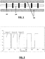
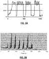
- Figure 1 shows an idealised drillstring structure (representing unit cells of pipe 104 and joint 102 within a surrounding casing 106) and Figure 2 illustrates the spectral response of a typical drillstring.
- Any communication solution that uses the drillstring as the wave-guide must utilise suitable parts of the spectrum for data transmission.
- the spectrum consists of a number of pass- and stop- bands, successful data transmission is only possible in the passbands.
- the periodic structure of a typical drillstring causes it to act as a mechanical filter; trapping (i.e. damping) all the signals with frequencies that lie within certain bands.
- the filtering effect occurs predominantly at the early stages of the structure.
- the filtered nulls, where frequencies do not propagate, are called stopbands; the frequencies where signals are allowed to propagate are called passbands.
- Additional factors affect the transmission path and attenuation (energy loss) of the propagating signal - such as tension, compression, wall contact, drilling fluid density and mode coupling.
- the noise in the channel may reduce or the attenuation may change thus providing an increase in usable bandwidth.
- the frequency dependent attenuation is more pronounced as the pipe sections here have been laid on the ground rather than mounted on isolating blocks.
- Certain bands may have more noise in them than others at any given time.
- the frequency of a "passband" (where communication is considered more effective) may vary over time.
- the conditions for wireless communications (using, for example, radio, optical, acoustic and/or ultrasonic technologies) in the downhole environment are typically hostile.
- Part of the hostility is the presence of dynamically changing conditions.
- coiled tubing is acoustically joint-less for long distances despite the welds (for example, helical welds) on the coiled tubing and it has a bandwidth of at least 2kHz. Therefore, the passband of coiled tubing is relatively wide (in comparison to those in jointed drillstring) and therefore allows higher telemetry rates. In view of this available bandwidth, broadband signalling techniques can be applied to downhole wireless communication using coiled tubing, channel distortion presents less of an obstacle to such broadband techniques. The use of telemetry on coiled tubing thereby provides additional data communication bandwidth.
- Wireless acoustic telemetry uses a solid medium (such as a jointed pipe or riser) as the mechanism for transmitting sound waves that contain data.
- a transmitter/receiver (Tx/Rx) tool is situated downhole and communicates with a Tx/Rx tool on surface.
- Two-way communication is a standard feature using sound waves both up and down the pipe.
- Current technology requires repeaters to boost the data-carrying sound wave over long distances, due to loss in the intensity of the signal, whilst the data transfer rate offered by such these systems is limited to around 40 bits per second.
- the reader is referred to an article entitled " An Overview of Acoustic Telemetry" by Drumheller, D.S, [Sandia National Laboratories, SAND -92 - 0677C ].
- the 40 bits/s data transfer rate is a mild improvement over the data transfer rates typical for traditional wireless telemetry systems such as mud pulse and electromagnetic (EM).
- Some of the factors that affect the intensity of the transmitted sound wave as it propagates along the jointed pipe are the characteristics of the well/casing, the deviation of the well, the extent of the contact between pipe and formation, the type of jointed pipe and its construction and whether or not there are packers in the transmission path. Any instantaneous variation in one or more of these could reduce the intensity of the sound wave and adversely affect communication.
- the effective range of operating frequencies for acoustic telemetry is believed to extend between 400 Hz and 2000 Hz: this one of a number of design considerations discussed in " Design Considerations for a New High Data Rate LWD Acoustic Telemetry System" Vimal, S. et al. [Society of Petroleum Engineers Paper, SPE 88636, Oct 2004 ]. This effective range suggests that a higher bandwidth is available than that of traditional wireless telemetry systems. Yet developers have been unable to take advantage of the higher bandwidth in order to significantly increase data transfer rates.
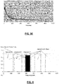
- the instantaneous variability (and noise) in the well means that current acoustic telemetry system developers have difficulty in locating the frequencies of all of the passbands, and therefore they limit their systems by electing to use only the central portion of a known band, or bands, to improve the chances of transmission.
- One such elected central portion of a passband is represented by the black segment in Figure 4 . This approach limits the bandwidth used by the data carrying sound wave and in turn reduces the bit rate.
- Certain known systems transmit in or near the respective centres of a plurality of the higher frequency bands in an effort to maximise transmission success. They avoid the lower bands of white space frequencies, e.g. 0-250Hz and 300-475Hz, because they are filled with environmental noise and deemed unsuitable. In all current systems, relays are always required to boost the signal beyond a maximum of 2,500m in a vertical deployment and 950m in a horizontal deployment.
- Certain downhole communications systems use chirp pulses to aid signal propagation.
- a chirp pulse offers a high signal to noise ratio and therefore allows transmission through high noise environments.
- the longer the pulse length the better the immunity to noise, however, current designs have to lower their bit-rate with increased chirp length.
- the conventional systems also rely on using a narrow section of the passbands in order to ensure that any variation in width or position of the band is compensated for. Only one passband is used in general, again limiting the performance and flexibility of the device.
- This prior system requires a bottom end modem to transmit a sequence of reference signals in the passbands that it is going to use. Digital phase lock loops are then used to detect these passband carrier tones. This approach is fragile as channel noise is likely to block these reference signals, especially in bands 1 and 2.
- Figure 5 illustrates the arrangement of certain functional components in an exemplary acoustic telemetry system.
- the system consists of a number of modem units connected acoustically to each other through the drillpipe or coiled tubing.
- the process contains at least two modem units, each capable of transmitting and receiving signals between each other. These modem units are denoted A 502 and D 504, such that unit A 502 is the surface end of the transmission path and unit D 504 at the downhole end.
- modem units B 512 and C 514 lie somewhere between modem units A 502 and D 504.
- Intermediate modem units along the transmission path from the two ends of the communication path can be of two types: either nodes or repeaters. Repeaters are required when reliable communications cannot be established between the two end modem units (A 502 and D 504, in this case). The reason could be loss of signal in noise. Repeaters may also be used to transmit local pressure and temperature signals from points along the string.
- Nodes are similar but do not re-transmit signals along the channel. That is, communications between the end modems can be achieved without the intervention of any nodes.
- the nodes treat the communications between the end modems as an acoustic backbone on to which they can piggy-back communications using TDM (time division multiplexing techniques).
- the form of the individual chirp pulse can be any pressure wave signal capable of pulse compression: non-limiting examples of suitable pulse forms include the “up” chirp, "down” chirp, “up-down” chirp, and “down-up” chirp illustrated in Figure 7 .
- the frequency range F1 to F2 will encompass all the available passbands in the channel.
- the reader will however note that pulses are not limited to sweeping frequencies with these bounds.
- the ensemble of chirp pulses transmitted by modem unit A 502 in operation S602 comprises an integer number, N, of non-overlapping chirp sequences.
- Figure 8 illustrates one such ensemble (i.e. a channel calibration Tx sequence) having a set of 8 identical transmission pulses. These pulses serve various purposes. Firstly, they are modified by the channel's transfer function so that information may be encapsulated and recovered by the receiving system. In addition, the use of such pulses increases the probability of the receiving system (i.e. modem unit D 504) detecting the sequence of pulse under noisy conditions, through unknown passband structures with unknown phase distortion. Chirp pulses also facilitate the provision of an ensemble of reference pulses for the purpose of removing noise as described below.
- Figure 11 shows the chirp pulse waveform of Figure 9 in 20 dB of noise.
- Figure 12 shows the noisy pulse of Figure 11 correlated with the pulse in Figure 9 .
- Figure 13 illustrates the time series for a typical up-chirp pulse
- Figure 14 illustrates the corresponding spectrum of that pulse.
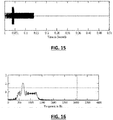
- Figures 15 and 16 illustrate the application of water-filling:
- Figure 15 shows a time series for a single up-chirp pulse that includes a period in which the chirp is transmitted at a higher amplitude: the high amplitude period is timed to coincide with the portion of the swept pulse corresponding to the 550-720 Hz band - giving a peak in that band in the resulting chirp spectrum illustrated in Figure 16 .
- amplitude modulation requires a power amplifier capable of delivering large increases in power level over relatively short time scales.
- the power amplifier must be configured to deliver peak powers far in excess of what is normally required of it.
- Chirp pulses can be generated over longer times in order to compensate for noise.
- lengthening the pulse has the side effect of increasing noise immunity in spectral bands where the noise is low and that increased immunity is not required. This is energy inefficient as more power is being applied to bands that do not require it.
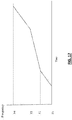
- FIG. 17 A simple example is shown in Figure 17 .
- the chirp sweeps a range from F1 to F4, however the portion of the sweep in frequencies is extended over a relatively longer time in the frequency range between F2 and F3.
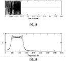
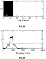
- Figure 20 shows the time series for the pulse in Figures 18 and 19 delayed and cross correlated with itself (i.e. decoded).
- Figure 21 shows the chirp pulse waveform of Figure 18 in 20 dB of white noise added the band between 700-1000 Hz.
- Attenuation may also be modelled in a similar way.
- the basic principal of selectively lengthening part(s) of the frequency range of a chirp pulse can be applied to any part of the spectrum that is weak (i.e. signal gain is low compared to other parts of the spectrum), whether that weakness is due to attenuation or the presence of noise levels above the mean for the spectra occupied by the chirp transmission.
- the claimed technique can thus be used to compensate for variations in the strength of pass bands in the channel.
- the conventional method of combating the above noise (or attenuation) is to increase the TB product of the chirp sweep overall. Using a TB of 512 recovers the chirp from the noise as shown in Figure 22 .
- TB Signal
- the decoded signal is above the level of the noise, it has been widened.
- the receiver In order to recover the full bandwidth of the signal, the receiver must implement a complementary de-emphasis function (i.e. correlation sequence).
- de-emphasis is not required. This is because the greater power in the attenuation band is required to counter a (local) reduction in receive power rather than to achieve a power level that exceeds the level of noise by a significant margin.
- Figure 26 shows the spectrum (i.e. a correlation reference) used at a correlator module of the receiver showing that the noise band spectrum is suppressed thus compensating for the gain in transmission signal, and also suppressing the in-band noise.
- spectrum i.e. a correlation reference
- the equalised correlator function in Figure 26 recovers the original broad band pulse from the noise.
- Figure 27 illustrates the degree of correlation and compares favourably with Figure 22 ).
- the reference transmission emphasised sequence is described above (see Figures 23 and 24 ).
- the de-emphasised correlation sequence is identical except that the amplitude of the equalised section as described above is attenuated in amplitude by the gain applied to this section (in this case, by a factor of 10), see Figure 28 .
- the white noise is applied in a certain frequency band (say 700MHz to 1100MHz) to model a frequency dependent noise effect. Where attenuation is to be modelled in a given frequency band, this can be done by applying a frequency dependent weighting factor to the model of a received signal.
- Figure 29 shows an example of a spectrum of an actual transmission line constructed of drill pipe (compare this with Figure 3E for a 41 pipe section drill pipe laid on the ground). While the three pass bands at or below 2000Hz are prominent, those at higher frequencies are significantly attenuated. Local extension of the chirp at these frequencies may thus be used to compensate for this comparative weakness.
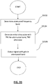
- Figure 30 illustrates a process sequence showing the main stages of a noise compensation method in accordance with certain embodiments of the present disclosure.
- a chirp pulse generator apparatus such as an acoustic transducer (i.e. a transceiver), which is operable over a plurality of frequency bands, determines which, if any, of the frequency bands (i.e. the "first" frequency bands) have propagation characteristics different from other frequency bands in that they experience a level of noise higher than that at the other frequency bands.
- an acoustic transducer i.e. a transceiver
- the apparatus generates an initial chirp pulse having a time bandwidth, TB, product with a first value for frequencies in the or each first frequency band and a TB product with a second value for frequencies in bands other than the or each first frequency band, the second value being lower than the first value.
- a receiving apparatus equalizing the initial chirp pulse by applying a correlator function.
- the correlator function having an amplitude modulated for that portion of the swept chirp pulse in which the first TB value is generated.
- the receiving apparatus is able to output an equalized signal where the noise is significantly attenuated yet the pulse length is restricted to a length capable of supporting a chirp pulse.
- Figure 31 illustrates a further process sequence showing the main stages of an attenuation compensation method in accordance with certain embodiments of the present disclosure.
- a chirp pulse generator apparatus e.g. acoustic transducer or other suitable transceiver
- the apparatus generates an initial chirp pulse having a time bandwidth, TB, product with a first value for frequencies in the or each first frequency band and a TB product with a second value for frequencies in bands other than the or each first frequency band, the second value being lower than the first value.
- a receiving apparatus applies a correlator function corresponding to the initial chirp pulse thereby outputting a signal where the attenuation is significantly reduced yet the pulse length is restricted to a length capable of supporting a chirp pulse.
Landscapes
- Engineering & Computer Science (AREA)
- Physics & Mathematics (AREA)
- Computer Networks & Wireless Communication (AREA)
- Signal Processing (AREA)
- Life Sciences & Earth Sciences (AREA)
- Mining & Mineral Resources (AREA)
- Geology (AREA)
- General Physics & Mathematics (AREA)
- Fluid Mechanics (AREA)
- Environmental & Geological Engineering (AREA)
- Geophysics (AREA)
- Remote Sensing (AREA)
- Acoustics & Sound (AREA)
- General Life Sciences & Earth Sciences (AREA)
- Geochemistry & Mineralogy (AREA)
- Spectroscopy & Molecular Physics (AREA)
- Power Engineering (AREA)
- Radar Systems Or Details Thereof (AREA)
- Geophysics And Detection Of Objects (AREA)
- Measurement Of Velocity Or Position Using Acoustic Or Ultrasonic Waves (AREA)
Claims (8)
- Procédé de génération d'une pluralité d'impulsions chirp pour une utilisation dans un canal de communication, le canal pouvant fonctionner sur une pluralité de bandes de fréquences, les bandes de fréquences comprenant au moins une première bande de fréquences ayant des caractéristiques de propagation différentes des autres bandes de fréquences, le procédé comprenant, au niveau d'un générateur d'impulsions chirp, les étapes suivantes :génération (s3004, s3104) d'une impulsion chirp initiale ayant une première valeur de produit de largeur de bande temporelle, produit TB, pour les fréquences dans chacune des au moins une première bande de fréquences et ayant une seconde valeur de produit TB pour les fréquences dans les bandes autres que l'au moins une première bande de fréquences, la seconde valeur étant inférieure à la première valeur,l'au moins une première bande de fréquences subissant une atténuation à un niveau supérieur au niveau d'atténuation dans les autres bandes de fréquences, ou l'au moins une première bande de fréquences subissant un niveau de bruit supérieur aux autres bandes de fréquences.
- Procédé selon la revendication 1, l'impulsion chirp étant une impulsion chirp linéaire.
- Procédé selon la revendication 1 ou 2, comprenant en outre, au niveau de l'appareil de réception, l'étape suivante :
compensation (s3006) de la différence entre la première et la seconde valeur du produit TB dans l'impulsion chirp initiale par l'application d'une fonction de corrélation. - Procédé selon l'une quelconque des revendications précédentes, le canal de communication étant un canal de télémétrie acoustique.
- Appareil (502, 504, 512, 514) conçu pour générer une pluralité d'impulsions chirp pour une utilisation dans un canal de communication, le canal pouvant fonctionner sur une pluralité de bandes de fréquences, les bandes de fréquences comprenant au moins une première bande de fréquences ayant des caractéristiques de propagation différentes des autres bandes de fréquences, l'appareil comprenant :des circuits de traitement conçus pour :
générer une impulsion chirp initiale ayant une première valeur de produit de largeur de bande temporelle, produit TB, pour les fréquences dans chacune des au moins une première bande de fréquences et une seconde valeur de produit TB pour les fréquences dans les bandes autres que l'au moins une première bande de fréquences, la seconde valeur étant inférieure à la première valeur,l'au moins une première bande de fréquences subissant une atténuation à un niveau supérieur au niveau d'atténuation dans les autres bandes de fréquences, ou l'au moins une première bande de fréquences subissant un niveau de bruit supérieur aux autres bandes de fréquences. - Appareil (502, 504, 512, 514) selon la revendication 5, comprenant en outre une unité de communication pour transmettre les impulsions chirp.
- Appareil (502, 504, 512, 514) selon la revendication 5 ou 6, le canal de communication étant un canal de télémétrie acoustique.
- Appareil (502, 504, 512, 514) selon l'une quelconque des revendications 5 à 7, l'impulsion chirp étant une impulsion chirp linéaire.
Applications Claiming Priority (1)
| Application Number | Priority Date | Filing Date | Title |
|---|---|---|---|
| GB1519471.5A GB2544066B (en) | 2015-11-04 | 2015-11-04 | Signal equalisation |
Publications (2)
| Publication Number | Publication Date |
|---|---|
| EP3166271A1 EP3166271A1 (fr) | 2017-05-10 |
| EP3166271B1 true EP3166271B1 (fr) | 2020-08-12 |
Family
ID=55130657
Family Applications (1)
| Application Number | Title | Priority Date | Filing Date |
|---|---|---|---|
| EP16197067.8A Active EP3166271B1 (fr) | 2015-11-04 | 2016-11-03 | Procédé et appareil d'égalisation de signal |
Country Status (4)
| Country | Link |
|---|---|
| US (2) | US9941924B2 (fr) |
| EP (1) | EP3166271B1 (fr) |
| DK (1) | DK3166271T3 (fr) |
| GB (1) | GB2544066B (fr) |
Families Citing this family (5)
| Publication number | Priority date | Publication date | Assignee | Title |
|---|---|---|---|---|
| GB2544066B (en) * | 2015-11-04 | 2019-11-13 | Raptor Oil Ltd | Signal equalisation |
| WO2019108184A1 (fr) * | 2017-11-29 | 2019-06-06 | Halliburton Energy Services, Inc. | Système de communication acoustique à travers un fluide |
| CA3133892A1 (fr) * | 2019-04-03 | 2020-10-08 | Raptor Data Limited | Determination de la pertinence d'une bande de frequences pour une communication |
| US11343123B2 (en) | 2020-10-27 | 2022-05-24 | Huawei Technologies Co., Ltd. | Sensing-assisted channel estimation |
| US12425128B2 (en) * | 2023-09-13 | 2025-09-23 | Analog Devices International Unlimited Company | High-immunity wireless communication for battery management systems |
Family Cites Families (9)
| Publication number | Priority date | Publication date | Assignee | Title |
|---|---|---|---|---|
| GB0108188D0 (en) | 2001-04-02 | 2001-08-15 | Secr Defence | Communication system for underwater use |
| CA2685688A1 (fr) * | 2008-11-28 | 2010-05-28 | Xact Downhole Telemetry Inc. | Retablissement et detection de signal ameliores du minutage du signal recu d'un fonds de puits |
| KR101268576B1 (ko) * | 2008-12-12 | 2013-05-28 | 한국전자통신연구원 | 무선 측위 신호 생성 장치 및 방법 |
| GB2475039B (en) * | 2009-10-30 | 2013-12-18 | Bios Developments Ltd | Methods for communicating and associated apparatus |
| TWI448094B (zh) * | 2012-09-24 | 2014-08-01 | Princeton Technology Corp | 雙啁啾序列調變系統和方法 |
| US9645228B1 (en) * | 2012-12-14 | 2017-05-09 | Sandia Corporation | Shaping the spectrum of random-phase radar waveforms |
| WO2014201440A1 (fr) * | 2013-06-14 | 2014-12-18 | Lockheed Martin Corporation | Système, procédé, et appareil de communication insensible à une erreur d'horloge d'échantillonnage |
| US9778226B2 (en) * | 2015-02-19 | 2017-10-03 | Saudi Arabian Oil Company | Slug flow monitoring and gas measurement |
| GB2544066B (en) * | 2015-11-04 | 2019-11-13 | Raptor Oil Ltd | Signal equalisation |
-
2015
- 2015-11-04 GB GB1519471.5A patent/GB2544066B/en active Active
-
2016
- 2016-11-03 DK DK16197067.8T patent/DK3166271T3/da active
- 2016-11-03 EP EP16197067.8A patent/EP3166271B1/fr active Active
- 2016-11-03 US US15/342,377 patent/US9941924B2/en active Active
-
2018
- 2018-02-23 US US15/903,350 patent/US10637529B2/en active Active
Non-Patent Citations (1)
| Title |
|---|
| None * |
Also Published As
| Publication number | Publication date |
|---|---|
| GB2544066B (en) | 2019-11-13 |
| DK3166271T3 (da) | 2020-11-02 |
| US20180183487A1 (en) | 2018-06-28 |
| US9941924B2 (en) | 2018-04-10 |
| GB201519471D0 (en) | 2015-12-16 |
| GB2544066A (en) | 2017-05-10 |
| US10637529B2 (en) | 2020-04-28 |
| EP3166271A1 (fr) | 2017-05-10 |
| US20170126271A1 (en) | 2017-05-04 |
Similar Documents
| Publication | Publication Date | Title |
|---|---|---|
| US10637529B2 (en) | Signal equalisation | |
| US20240151138A1 (en) | Determining frequency band suitability for communication | |
| US6880634B2 (en) | Coiled tubing acoustic telemetry system and method | |
| US9822634B2 (en) | Downhole telemetry systems and methods with time-reversal pre-equalization | |
| US10677049B2 (en) | Downhole low rate linear repeater relay network timing system and method | |
| US20130278432A1 (en) | Simultaneous Data Transmission of Multiple Nodes | |
| US20100171639A1 (en) | Wellbore telemetry and noise cancellation systems and methods for the same | |
| WO2007095111A1 (fr) | Système et procédé de télémétrie pendant le forage | |
| US9042200B2 (en) | Downhole telemetry system | |
| US20140254322A1 (en) | Telemetry Coding and Surface Detection for a Mud Pulser | |
| WO2006110391A2 (fr) | Systeme et procedes de communication sur des canaux de communication bruyants | |
| AU2012378310B2 (en) | Simultaneous data transmission of multiple nodes | |
| Islam et al. | Vibrational data communication tools and methods for mining and oil and gas extraction | |
| AU2014415553B2 (en) | Wide bandwidth drill pipe structure for acoustic telemetry | |
| RU2778079C1 (ru) | Ретранслятор скважинной электромагнитной телеметрии | |
| Ahmad et al. | Multiphase acoustic channel characterization for downhole communication | |
| BR122023005935B1 (pt) | Aparelho, método para receber um sinal de comunicação, método de transmissão de um sinal de comunicação, sistema de comunicação, produto de programa de computador, e um ou mais meios legíveis por computador não transitórios | |
| BR122023005991B1 (pt) | Aparelho para receber sinais de comunicação, método para receber sinais de comunicação, método de transmissão de sinais de comunicação, produto de programa de computador, e sistema de comunicação | |
| BR112021019370B1 (pt) | Aparelho, sistema e método para determinar a adequação de uma banda de frequência para comunicação de dados com um nó por meio de um canal de comunicação | |
| EP3114317B1 (fr) | Système et procédé de synchronisation de réseau relais de répéteurs linéaires à faible débit de fond de puits | |
| GB2472535A (en) | Noise in a first communication channel is estimated and compensated for using noise measurements in adjacent channels |
Legal Events
| Date | Code | Title | Description |
|---|---|---|---|
| PUAI | Public reference made under article 153(3) epc to a published international application that has entered the european phase |
Free format text: ORIGINAL CODE: 0009012 |
|
| STAA | Information on the status of an ep patent application or granted ep patent |
Free format text: STATUS: THE APPLICATION HAS BEEN PUBLISHED |
|
| AK | Designated contracting states |
Kind code of ref document: A1 Designated state(s): AL AT BE BG CH CY CZ DE DK EE ES FI FR GB GR HR HU IE IS IT LI LT LU LV MC MK MT NL NO PL PT RO RS SE SI SK SM TR |
|
| AX | Request for extension of the european patent |
Extension state: BA ME |
|
| STAA | Information on the status of an ep patent application or granted ep patent |
Free format text: STATUS: REQUEST FOR EXAMINATION WAS MADE |
|
| 17P | Request for examination filed |
Effective date: 20171011 |
|
| RBV | Designated contracting states (corrected) |
Designated state(s): AL AT BE BG CH CY CZ DE DK EE ES FI FR GB GR HR HU IE IS IT LI LT LU LV MC MK MT NL NO PL PT RO RS SE SI SK SM TR |
|
| STAA | Information on the status of an ep patent application or granted ep patent |
Free format text: STATUS: EXAMINATION IS IN PROGRESS |
|
| 17Q | First examination report despatched |
Effective date: 20190718 |
|
| RIN1 | Information on inventor provided before grant (corrected) |
Inventor name: MACLEAN, COLIN Inventor name: COWIE, GORDON |
|
| GRAP | Despatch of communication of intention to grant a patent |
Free format text: ORIGINAL CODE: EPIDOSNIGR1 |
|
| STAA | Information on the status of an ep patent application or granted ep patent |
Free format text: STATUS: GRANT OF PATENT IS INTENDED |
|
| INTG | Intention to grant announced |
Effective date: 20200508 |
|
| GRAS | Grant fee paid |
Free format text: ORIGINAL CODE: EPIDOSNIGR3 |
|
| GRAJ | Information related to disapproval of communication of intention to grant by the applicant or resumption of examination proceedings by the epo deleted |
Free format text: ORIGINAL CODE: EPIDOSDIGR1 |
|
| GRAL | Information related to payment of fee for publishing/printing deleted |
Free format text: ORIGINAL CODE: EPIDOSDIGR3 |
|
| STAA | Information on the status of an ep patent application or granted ep patent |
Free format text: STATUS: EXAMINATION IS IN PROGRESS |
|
| GRAR | Information related to intention to grant a patent recorded |
Free format text: ORIGINAL CODE: EPIDOSNIGR71 |
|
| STAA | Information on the status of an ep patent application or granted ep patent |
Free format text: STATUS: GRANT OF PATENT IS INTENDED |
|
| GRAA | (expected) grant |
Free format text: ORIGINAL CODE: 0009210 |
|
| STAA | Information on the status of an ep patent application or granted ep patent |
Free format text: STATUS: THE PATENT HAS BEEN GRANTED |
|
| INTC | Intention to grant announced (deleted) | ||
| AK | Designated contracting states |
Kind code of ref document: B1 Designated state(s): AL AT BE BG CH CY CZ DE DK EE ES FI FR GB GR HR HU IE IS IT LI LT LU LV MC MK MT NL NO PL PT RO RS SE SI SK SM TR |
|
| INTG | Intention to grant announced |
Effective date: 20200706 |
|
| REG | Reference to a national code |
Ref country code: CH Ref legal event code: EP |
|
| REG | Reference to a national code |
Ref country code: IE Ref legal event code: FG4D |
|
| REG | Reference to a national code |
Ref country code: DE Ref legal event code: R096 Ref document number: 602016041759 Country of ref document: DE |
|
| REG | Reference to a national code |
Ref country code: AT Ref legal event code: REF Ref document number: 1302665 Country of ref document: AT Kind code of ref document: T Effective date: 20200915 |
|
| REG | Reference to a national code |
Ref country code: NO Ref legal event code: T2 Effective date: 20200812 Ref country code: DK Ref legal event code: T3 Effective date: 20201027 |
|
| REG | Reference to a national code |
Ref country code: NL Ref legal event code: FP |
|
| REG | Reference to a national code |
Ref country code: LT Ref legal event code: MG4D |
|
| PG25 | Lapsed in a contracting state [announced via postgrant information from national office to epo] |
Ref country code: LT Free format text: LAPSE BECAUSE OF FAILURE TO SUBMIT A TRANSLATION OF THE DESCRIPTION OR TO PAY THE FEE WITHIN THE PRESCRIBED TIME-LIMIT Effective date: 20200812 Ref country code: FI Free format text: LAPSE BECAUSE OF FAILURE TO SUBMIT A TRANSLATION OF THE DESCRIPTION OR TO PAY THE FEE WITHIN THE PRESCRIBED TIME-LIMIT Effective date: 20200812 Ref country code: SE Free format text: LAPSE BECAUSE OF FAILURE TO SUBMIT A TRANSLATION OF THE DESCRIPTION OR TO PAY THE FEE WITHIN THE PRESCRIBED TIME-LIMIT Effective date: 20200812 Ref country code: HR Free format text: LAPSE BECAUSE OF FAILURE TO SUBMIT A TRANSLATION OF THE DESCRIPTION OR TO PAY THE FEE WITHIN THE PRESCRIBED TIME-LIMIT Effective date: 20200812 Ref country code: GR Free format text: LAPSE BECAUSE OF FAILURE TO SUBMIT A TRANSLATION OF THE DESCRIPTION OR TO PAY THE FEE WITHIN THE PRESCRIBED TIME-LIMIT Effective date: 20201113 Ref country code: BG Free format text: LAPSE BECAUSE OF FAILURE TO SUBMIT A TRANSLATION OF THE DESCRIPTION OR TO PAY THE FEE WITHIN THE PRESCRIBED TIME-LIMIT Effective date: 20201112 |
|
| REG | Reference to a national code |
Ref country code: AT Ref legal event code: MK05 Ref document number: 1302665 Country of ref document: AT Kind code of ref document: T Effective date: 20200812 |
|
| PG25 | Lapsed in a contracting state [announced via postgrant information from national office to epo] |
Ref country code: RS Free format text: LAPSE BECAUSE OF FAILURE TO SUBMIT A TRANSLATION OF THE DESCRIPTION OR TO PAY THE FEE WITHIN THE PRESCRIBED TIME-LIMIT Effective date: 20200812 Ref country code: PL Free format text: LAPSE BECAUSE OF FAILURE TO SUBMIT A TRANSLATION OF THE DESCRIPTION OR TO PAY THE FEE WITHIN THE PRESCRIBED TIME-LIMIT Effective date: 20200812 Ref country code: LV Free format text: LAPSE BECAUSE OF FAILURE TO SUBMIT A TRANSLATION OF THE DESCRIPTION OR TO PAY THE FEE WITHIN THE PRESCRIBED TIME-LIMIT Effective date: 20200812 Ref country code: IS Free format text: LAPSE BECAUSE OF FAILURE TO SUBMIT A TRANSLATION OF THE DESCRIPTION OR TO PAY THE FEE WITHIN THE PRESCRIBED TIME-LIMIT Effective date: 20201212 |
|
| PG25 | Lapsed in a contracting state [announced via postgrant information from national office to epo] |
Ref country code: EE Free format text: LAPSE BECAUSE OF FAILURE TO SUBMIT A TRANSLATION OF THE DESCRIPTION OR TO PAY THE FEE WITHIN THE PRESCRIBED TIME-LIMIT Effective date: 20200812 Ref country code: SM Free format text: LAPSE BECAUSE OF FAILURE TO SUBMIT A TRANSLATION OF THE DESCRIPTION OR TO PAY THE FEE WITHIN THE PRESCRIBED TIME-LIMIT Effective date: 20200812 Ref country code: RO Free format text: LAPSE BECAUSE OF FAILURE TO SUBMIT A TRANSLATION OF THE DESCRIPTION OR TO PAY THE FEE WITHIN THE PRESCRIBED TIME-LIMIT Effective date: 20200812 Ref country code: CZ Free format text: LAPSE BECAUSE OF FAILURE TO SUBMIT A TRANSLATION OF THE DESCRIPTION OR TO PAY THE FEE WITHIN THE PRESCRIBED TIME-LIMIT Effective date: 20200812 |
|
| REG | Reference to a national code |
Ref country code: DE Ref legal event code: R097 Ref document number: 602016041759 Country of ref document: DE |
|
| PG25 | Lapsed in a contracting state [announced via postgrant information from national office to epo] |
Ref country code: ES Free format text: LAPSE BECAUSE OF FAILURE TO SUBMIT A TRANSLATION OF THE DESCRIPTION OR TO PAY THE FEE WITHIN THE PRESCRIBED TIME-LIMIT Effective date: 20200812 Ref country code: AL Free format text: LAPSE BECAUSE OF FAILURE TO SUBMIT A TRANSLATION OF THE DESCRIPTION OR TO PAY THE FEE WITHIN THE PRESCRIBED TIME-LIMIT Effective date: 20200812 Ref country code: AT Free format text: LAPSE BECAUSE OF FAILURE TO SUBMIT A TRANSLATION OF THE DESCRIPTION OR TO PAY THE FEE WITHIN THE PRESCRIBED TIME-LIMIT Effective date: 20200812 |
|
| REG | Reference to a national code |
Ref country code: DE Ref legal event code: R119 Ref document number: 602016041759 Country of ref document: DE |
|
| PLBE | No opposition filed within time limit |
Free format text: ORIGINAL CODE: 0009261 |
|
| STAA | Information on the status of an ep patent application or granted ep patent |
Free format text: STATUS: NO OPPOSITION FILED WITHIN TIME LIMIT |
|
| PG25 | Lapsed in a contracting state [announced via postgrant information from national office to epo] |
Ref country code: MC Free format text: LAPSE BECAUSE OF FAILURE TO SUBMIT A TRANSLATION OF THE DESCRIPTION OR TO PAY THE FEE WITHIN THE PRESCRIBED TIME-LIMIT Effective date: 20200812 Ref country code: SK Free format text: LAPSE BECAUSE OF FAILURE TO SUBMIT A TRANSLATION OF THE DESCRIPTION OR TO PAY THE FEE WITHIN THE PRESCRIBED TIME-LIMIT Effective date: 20200812 |
|
| REG | Reference to a national code |
Ref country code: CH Ref legal event code: PL |
|
| 26N | No opposition filed |
Effective date: 20210514 |
|
| PG25 | Lapsed in a contracting state [announced via postgrant information from national office to epo] |
Ref country code: LU Free format text: LAPSE BECAUSE OF NON-PAYMENT OF DUE FEES Effective date: 20201103 Ref country code: IT Free format text: LAPSE BECAUSE OF FAILURE TO SUBMIT A TRANSLATION OF THE DESCRIPTION OR TO PAY THE FEE WITHIN THE PRESCRIBED TIME-LIMIT Effective date: 20200812 |
|
| REG | Reference to a national code |
Ref country code: BE Ref legal event code: MM Effective date: 20201130 |
|
| PG25 | Lapsed in a contracting state [announced via postgrant information from national office to epo] |
Ref country code: SI Free format text: LAPSE BECAUSE OF FAILURE TO SUBMIT A TRANSLATION OF THE DESCRIPTION OR TO PAY THE FEE WITHIN THE PRESCRIBED TIME-LIMIT Effective date: 20200812 Ref country code: LI Free format text: LAPSE BECAUSE OF NON-PAYMENT OF DUE FEES Effective date: 20201130 Ref country code: CH Free format text: LAPSE BECAUSE OF NON-PAYMENT OF DUE FEES Effective date: 20201130 |
|
| PG25 | Lapsed in a contracting state [announced via postgrant information from national office to epo] |
Ref country code: FR Free format text: LAPSE BECAUSE OF NON-PAYMENT OF DUE FEES Effective date: 20201130 Ref country code: IE Free format text: LAPSE BECAUSE OF NON-PAYMENT OF DUE FEES Effective date: 20201103 |
|
| PG25 | Lapsed in a contracting state [announced via postgrant information from national office to epo] |
Ref country code: DE Free format text: LAPSE BECAUSE OF NON-PAYMENT OF DUE FEES Effective date: 20210601 |
|
| REG | Reference to a national code |
Ref country code: NO Ref legal event code: CHAD Owner name: RAPTOR DATA LIMITED, GB |
|
| REG | Reference to a national code |
Ref country code: NL Ref legal event code: HC Owner name: RAPTOR DATA LIMITED; GB Free format text: DETAILS ASSIGNMENT: CHANGE OF OWNER(S), CHANGE OF OWNER(S) NAME; FORMER OWNER NAME: RAPTOR OIL LIMITED Effective date: 20211119 |
|
| PG25 | Lapsed in a contracting state [announced via postgrant information from national office to epo] |
Ref country code: TR Free format text: LAPSE BECAUSE OF FAILURE TO SUBMIT A TRANSLATION OF THE DESCRIPTION OR TO PAY THE FEE WITHIN THE PRESCRIBED TIME-LIMIT Effective date: 20200812 Ref country code: MT Free format text: LAPSE BECAUSE OF FAILURE TO SUBMIT A TRANSLATION OF THE DESCRIPTION OR TO PAY THE FEE WITHIN THE PRESCRIBED TIME-LIMIT Effective date: 20200812 Ref country code: CY Free format text: LAPSE BECAUSE OF FAILURE TO SUBMIT A TRANSLATION OF THE DESCRIPTION OR TO PAY THE FEE WITHIN THE PRESCRIBED TIME-LIMIT Effective date: 20200812 |
|
| PG25 | Lapsed in a contracting state [announced via postgrant information from national office to epo] |
Ref country code: MK Free format text: LAPSE BECAUSE OF FAILURE TO SUBMIT A TRANSLATION OF THE DESCRIPTION OR TO PAY THE FEE WITHIN THE PRESCRIBED TIME-LIMIT Effective date: 20200812 |
|
| PG25 | Lapsed in a contracting state [announced via postgrant information from national office to epo] |
Ref country code: PT Free format text: LAPSE BECAUSE OF FAILURE TO SUBMIT A TRANSLATION OF THE DESCRIPTION OR TO PAY THE FEE WITHIN THE PRESCRIBED TIME-LIMIT Effective date: 20200812 Ref country code: BE Free format text: LAPSE BECAUSE OF NON-PAYMENT OF DUE FEES Effective date: 20201130 |
|
| PGFP | Annual fee paid to national office [announced via postgrant information from national office to epo] |
Ref country code: NL Payment date: 20251127 Year of fee payment: 10 |
|
| PGFP | Annual fee paid to national office [announced via postgrant information from national office to epo] |
Ref country code: GB Payment date: 20251125 Year of fee payment: 10 |
|
| PGFP | Annual fee paid to national office [announced via postgrant information from national office to epo] |
Ref country code: NO Payment date: 20251201 Year of fee payment: 10 |
|
| PGFP | Annual fee paid to national office [announced via postgrant information from national office to epo] |
Ref country code: DK Payment date: 20251127 Year of fee payment: 10 |