EP3166236B1 - Convoyeur-transporteur - Google Patents
Convoyeur-transporteur Download PDFInfo
- Publication number
- EP3166236B1 EP3166236B1 EP16194991.2A EP16194991A EP3166236B1 EP 3166236 B1 EP3166236 B1 EP 3166236B1 EP 16194991 A EP16194991 A EP 16194991A EP 3166236 B1 EP3166236 B1 EP 3166236B1
- Authority
- EP
- European Patent Office
- Prior art keywords
- transmitting
- receiving unit
- distance
- information
- time
- Prior art date
- Legal status (The legal status is an assumption and is not a legal conclusion. Google has not performed a legal analysis and makes no representation as to the accuracy of the status listed.)
- Active
Links
Images



Classifications
-
- H—ELECTRICITY
- H04—ELECTRIC COMMUNICATION TECHNIQUE
- H04B—TRANSMISSION
- H04B10/00—Transmission systems employing electromagnetic waves other than radio-waves, e.g. infrared, visible or ultraviolet light, or employing corpuscular radiation, e.g. quantum communication
- H04B10/11—Arrangements specific to free-space transmission, i.e. transmission through air or vacuum
- H04B10/114—Indoor or close-range type systems
- H04B10/1143—Bidirectional transmission
Definitions
- the invention relates to conveyor systems and methods of operating them.
- German patent specification DE 44 35 056 B4 describes - in connection with a method and a device for storing goods - a conveyor device which has movable transport devices in the form of so-called conveyors.
- the disclosure document DE 10 2013 001 358 A1 describes a method for determining the position of a vehicle on a plane.
- the pamphlet DE 600 16 933 T2 discloses a position locating system for determining the position of a mobile communication device or mobile terminal and, in particular, a system that allows two-way transmission of spread spectrum measurement signals between the mobile communication device and reference communication devices Clocks or timers of relatively low accuracy are used to quickly and accurately locate the position of the mobile communication device in the presence of more serious or strong multipath or multipath interference or disturbances to be determined.
- a conveyor with the features according to the preamble of claim 1 is in the German utility model DE 20 2013 105 384 U1 disclosed.
- the invention is based on the object of specifying a conveying device which enables particularly safe operation.
- a significant advantage of the conveyor device according to the invention is that both user data, for example for sending control commands for the purpose of controlling the conveyor device, and information for determining the distance can be transmitted via the optical free-jet communication system. It is thus advantageously possible to dispense with an external, separate determination of the distance of the displaceable transport device and to carry this out solely on the basis of the signals transmitted via the optical free-jet communication system.
- the determined distance value can be used, for example, to control the conveying device; the determined distance value can also be used to clear an area between the movable transport device and the other section of the conveyor device, for example for other vehicles or people passing by. With a view to the latter case in particular, it is important to determine the distance as precisely and promptly as possible; the conveyor device according to the invention can accomplish this in an advantageous manner make use of the open beam optical communication system.
- control unit of the second transmitting and receiving unit is designed in such a way that it uses its transmitter to transmit the information, the information, parts of the information or parts of the information in unused packet sections of the useful data packets.
- control unit of the second transmitting and receiving unit can be designed in such a way that it uses its transmitter to transmit the information, the information, parts of the information or parts of the information in separate information packets that are sent between user data packets, in particular immediately before or after user data packets .
- control unit of the second transmitting and receiving unit it is considered advantageous if it has a communication module for transmitting the useful data packets and a distance determination module.
- the distance determination module of the second sending and receiving unit is preferably designed such that it detects or determines the time span between the receipt of a data packet sent by the first sending and receiving unit and the subsequent sending of a data packet (e.g. response packet) first transmitting and receiving unit has passed or will pass, and the recorded period of time is transmitted as the information or one of the information to the communication module of its (that is, the second) transmitting and receiving unit.
- a data packet e.g. response packet
- the communication module of the second transmitting and receiving unit is preferably designed in such a way that it transmits the recorded period of time as the information or one of the information in unused packet sections of the user data packets and / or in separate information packets to the first transmitting and receiving unit.
- the control unit of the first transmitting and receiving unit preferably has a distance determination module which is designed such that it detects the total time span between the sending of the own data packet to the second transmitting and receiving unit and the reception of the one received by the second transmitting and receiving unit Data packet passes, and the distance is determined on the basis of the self-recorded total time period and the time period recorded by the second transmitting and receiving unit and received as information.
- the at least two transmitting and receiving units are preferably each designed in such a way that they can be used both as one and can work as the other transmitting and receiving unit or as both the first and the second transmitting and receiving unit and both transmitting and receiving units each use one or more received information items from the other transmitting and receiving unit to determine the spatial Can determine the distance between the two transmitting and receiving units.
- the control unit preferably has a computer device and a memory in which software modules are stored, one of which forms the distance determination module when executed by the computer device and the communication module when executed by the control unit.
- control units of the two transmitting and receiving units are each designed in such a way that they send a received signal, in particular its data packets or at least one predetermined type of data packets, to the presence of a device identifier that identifies the other transmitting and receiving unit , check and discard the received signal, in particular the respective data packet, in whole or in part, if the received signal or the respective data packet does not contain a device identifier that identifies the other transmitting and receiving unit.
- One advantage of this refinement is that it enables particularly secure and error-free transmission of data or information because only data packets with the correct device identifier can be used and others can be discarded.
- distance information is transmitted within the framework of the data packets or distance information is obtained from or with the data packets, for example by clock edge evaluation, and based on this of this distance information, an area between the movable transport device and the other section of the conveyor device is to be released, for example for other vehicles or people passing by.
- control units of both transmitting and receiving units are each designed in such a way that they determine the spatial distance between the two transmitting and receiving units using information that enables or supports the determination of the distance, or more such information determine which are received by the respective other transmitting and receiving unit, and the control units are also each designed in such a way that a received data packet, which has information that enables or supports the distance determination, for the presence of the device identifier that the other
- the transmitting and receiving unit is identified, checked and the information contained in the respective data packet is only used to determine the spatial distance if the device identifier is contained in the respective data packet, and otherwise do not take the received signal into account when determining the distance.
- control units of both transmitting and receiving units preferably each have a distance determination module which is designed such that it determines the spatial distance between the two transmitting and receiving units using one or more pieces of information received from the other transmitting and receiving unit will.
- control units of both transmitting and receiving units preferably each have a verification module which is designed in such a way that a received data packet, which has information that enables or supports the determination of the distance, to the presence of the device identifier that the respective other transmit and receiving unit identifies and checks the information contained in the data packet for determining the spatial distance for evaluation by the distance determination module only if the received signal contains the device identifier that identifies the other sending and receiving unit, and otherwise the information is used blocked.
- a checksum control module of the verification module is preferably designed in such a way that it carries out a specified checksum check for a data packet to be checked and only releases information contained in the data packet for determining the spatial distance for evaluation by the distance determination module if the checksum control confirms that the received device identifier is free from errors confirmed or errors contained in the device identification can be corrected using the respective checksum, and otherwise the use of the information is blocked.
- the checksum control module can also be designed in such a way that it only releases information contained in the data packet for determining the spatial distance for evaluation by the distance determination module if the checksum control confirms or ascertains that the information for determining the spatial distance is free from errors correct mistakes otherwise the utilization of the information is blocked.
- control units in particular their checksum control modules, are preferably designed in such a way that they carry out a cyclical redundancy check for data packets to be checked and / or their distance information.
- control units in particular their distance determination modules, are designed in such a way that they exchange and compare determined distance values, which indicate the spatial distance between the two transmitting and receiving units, and in the event that the discrepancy between the two themselves determined , own distance values and the distance values received from the respective other transmitting and receiving unit reaches or exceeds a predetermined maximum difference, generate an error signal.
- a checksum is preferably formed for each of these, which is transmitted together with the distance values or separately from them to the respective other transmitting and receiving unit so that the latter can check the distance values for correctness and, if necessary, a Can correct errors.
- the transmitting and receiving units each include a data buffer and the control units are each designed in such a way that they determine a buffer time period for each data packet or at least for a specified type of data packet before sending, for which the respective data packet is to be cached prior to being sent to the other transmitting and receiving unit, the data packet for store the respective buffer time span in the data buffer and only then transmit it to the other transmitting and receiving unit.
- the buffer time periods are preferably determined in each case in such a way that they correspond to a predetermined maximum buffer time period minus the runtime of the respective data packet to the respective other transmitting and receiving unit, as forecast by the control unit.
- the buffering enables all data packets to arrive at the same time interval independently or at least largely independently of the respective spatial distance between the sending and receiving units and the "packet cycle" or the packet rate is distance-independent or at least largely distance-independent. Since the "packet cycle" or the packet rate is or is more or less fixed, the processing of the data packets can be simplified because the arrival of the next data packet can be expected. For example, foreign or falsified data packets that have a different clock rate or that arrive at an inopportune time can also be recognized and discarded.
- control units of both transmitting and receiving units are each designed in such a way that they determine the spatial distance between the two transmitting and receiving units by forming a distance value and, taking this distance value into account, the transit time of the respective Predict data packets.
- the control units of both transmitting and receiving units preferably each have a delay module that each has a buffer time span for the data packets to be transmitted or at least for a predetermined type of data packets, in particular useful data packets or separate information packets determined for which the respective data packet is to be cached before being sent to the other transmitting and receiving unit.
- the control units of both transmitting and receiving units preferably each have a delay memory, the memory size of which is at least as large as the product of the data rate on the optical free-beam communication link and the maximum buffer time span.
- the following therefore preferably applies: SG ⁇ PSMmax * fd where SG denotes the memory size of the delay memory, PZSmax denotes the maximum buffer time span and fd denotes the data rate on the optical free-beam communication link.
- the conveying device preferably forms a lifting device, an elevator or a crane.
- the movable transport device is preferably formed by a trolley of a warehouse, in particular a shelf storage, a lifting element of a lifting device or a car or a movable lifting element of an elevator.
- the displaceable transport device is preferably a linearly displaceable transport device.
- the invention also relates to a method for operating a conveyor device.
- the invention provides that the spatial distance between a movable transport device of the conveyor device and another, in particular stationary, section of the conveyor is determined, with at least two transmitting and receiving units, each comprising a transmitter, a receiver and a control unit and of which one is attached to the movable transport device and the other is attached to the other section, in an optical free-beam communication link are operated and user data packets are transmitted in a predetermined optical transmission channel, the data transmission capacity of the transmission channel being larger than the minimum data transmission capacity required to transmit the user data packets and the transmission channel thus providing a free channel area and at least one (preferably both) of the transmitting and receiving units - hereinafter referred to as the first transmitting and receiving unit - determining the spatial distance between the two transmitting and receiving units using one or more pieces of information t, which are received in the free channel area by the respective other transmitting and receiving unit - hereinafter referred to as the second transmitting and receiving unit.
- control unit of the second transmitting and receiving unit detects or determines the time span between the receipt of a data packet sent by the first transmitting and receiving unit and the subsequent sending of a data packet (e.g. response packet) to the first Sender and receiver unit has passed or will pass, and as the information or one of the information, the respective recorded time period is transmitted to the first transmitting and receiving unit.
- the control unit of the second transmitting and receiving unit transmits the information or parts of the information preferably in unused packet sections of the payload data packets and / or in separate information packets that are sent between payload data packets, in particular immediately before or after payload data packets.
- the control unit of the first transmitting and receiving unit preferably records the total time that elapses between sending a separate data packet to the second transmitting and receiving unit and receiving a data packet (e.g. response packet) subsequently received by the second transmitting and receiving unit.
- the control unit of the first transmitting and receiving unit preferably determines the distance on the basis of the self-recorded total time period and the time period recorded by the second transmitting and receiving unit and received as information.
- the Figure 1 shows, in a simplified schematic representation, an exemplary embodiment for a conveyor device 10 according to the invention, which can be, for example, a lifting device, an elevator, a crane or the like.
- the conveying device 10 forms part of an automated rack storage system and includes, inter alia, a movable transport device 20, for example in the form of a trolley that can be moved linearly in the direction of the arrow X.
- the conveyor device 10 has an optical free-jet communication system 30 which enables an optical free-beam communication connection 40 between the movable transport device 20 and on another section 11, for example a fixed section or another trolley, of the conveyor device 10.
- the free-jet communication system 30 comprises a first transmitting and receiving unit 101 attached to the movable transport device 20 and a second transmitting and receiving unit 102 attached to the other section 11 of the conveying device 10.
- the two transmitting and receiving units 101 and 102 are preferably identical in construction and can accordingly operated in an identical manner.
- the operating mode explained below by way of example for the first transmitting and receiving unit 101 can accordingly be carried out in a corresponding manner by the second transmitting and receiving unit 102, and vice versa.
- the two transmitting and receiving units 101 and 102 each include a transmitter 110, a receiver 120 and a control unit 130 and are in the optical free-beam communication link 40 for the purpose of transmitting user data packets NDP.
- the user data packets NDP are preferably transmitted in a predetermined optical transmission channel. It is considered to be advantageous if the data transmission capacity of the transmission channel is larger than the minimum data transmission capacity required to transmit the user data packets NDP, so that the transmission channel provides a free channel area. In the case of such a design of the optical free-jet communication link 40, it is possible, for example, to transmit additional information which enables the distance S or the spatial distance between the two transmitting and receiving units 101 and 102 to be determined.
- the distance S can be used to control the conveyor device 10, for example to clear an area between the movable transport device 20 and the other section 11 of the conveyor device 10, for example for other vehicles or people passing by. For this reason it is important that the distance S is determined as precisely as possible and transmitted with as few errors as possible; because an incorrect distance specification could cause an accident.
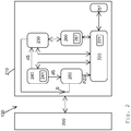
- FIG. 11 shows an exemplary embodiment for a control unit 130, which is in the two transmitting and receiving units 101 and 102 according to FIG Figure 1 can be used.
- the control unit 130 comprises a computing device 200, which is preferably a microprocessor device, and a memory 210.
- a computing device 200 which is preferably a microprocessor device
- a memory 210 In the memory 210 there is a A multiplicity of program modules are stored which can be executed by the computing device 200 and, when executed by the computing device 200, preferably form a communication module 220, a distance determination module 230, a distance change detection module 240, a delay module 250 and a verification module 260.
- the communication module 220 is connected to the transmitter 110 and the receiver 120 and handles the optical free-beam communication link 40 between the two transmitting and receiving units 101 and 102.
- the Figure 3 shows an example of a stream of user data packets NDP over time t that can be generated by communication module 220 for the purpose of sending or received by communication module 220 of the other transmitting and receiving unit.
- Process data and control data for controlling and operating the conveyor device 10 can be transmitted in the user data packets NDP.
- the distance determination module 230 is connected to the communication module 220.
- the task of the distance determination module 230 is to evaluate information I which is transmitted between the two transmitting and receiving units via the free-beam communication link 40 and which enables a distance to be determined.
- the information I can be transmitted in unused packet sections of the user data packets NDP, as in the Figure 4 is shown by way of example, or in separate information packets IP, as in the Figure 5 is shown by way of example.
- the information I that is transmitted via the free-jet communication link 40 is preferably a time stamp.
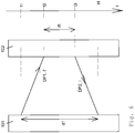
- the distance determination module 230 of the first transmitting and receiving unit 101 records the total time span dT that elapsed between the sending of a separate data packet DP1 (e.g. user data packet or separate information packet) to the second transmitting and receiving unit 102 (see time t1 in Figure 6 ) and the subsequent reception of a data packet DP2 received by the second transmitting and receiving unit 102, also referred to below as a response data packet, passes (see time t4 in FIG Figure 6 ).
- a separate data packet DP1 e.g. user data packet or separate information packet
- the distance determination module 230 of the second transmitting and receiving unit 102 determines the time span dt between the reception of the data packet DP1 sent by the first transmitting and receiving unit 101 (see time t2 in FIG Figure 6 ) and the subsequent sending of the response data packet (see time t3 in Figure 6 ) to the first transmitting and receiving unit 101 has passed or will pass, and transmits this recorded time period dt as information I to the first transmitting and receiving unit 101.
- the time period dt is formed by forming the difference between the times t2 and t3.
- the distance determining module 230 of the first transmitting and receiving unit 101 also transmits the time span (information I ') that elapsed between the reception of one of the second transmitting and receiving units. and receiving unit 102 sent data packets (in Figure 6 not shown) and the subsequent sending of the data packet DP1 to the second transmitting and receiving unit 102 has passed or will pass.
- the distance determination module 230 of the second transmitting and receiving unit 102 can calculate the distance S in a corresponding or identical manner, as has been explained in connection with the first transmitting and receiving unit 101.
- the distance determination modules 230 of the two transmitting and receiving units thus enable a regular absolute measurement of the distance S or a regular determination of a corresponding absolute distance measurement value S between the transmitting and receiving units, namely according to the temporal rate of the transmitted data packets.
- the distance determination modules 230 of the two transmitting and receiving units preferably exchange the distance values determined by them with one another and compare them. In the event that the discrepancy between their own distance values and the distance values received by the other two transmitting and receiving units reaches or exceeds a predetermined maximum difference, the distance determination modules 230 preferably generate an error signal.
- control device 130 is in accordance with FIG Figure 2 equipped with the distance change detection module 240.
- the distance change detection module 240 is connected to the communication module 220 and generates with the optical received signal Pin (t) received via the optical free-beam connection 40, i.e. with the stream of incoming data packets (see FIG Figures 3 to 5 ) a receive clock signal Ta (t), which is exemplified in the Figure 7 is shown over time t.
- the distance change detection module 240 can determine the times of rising and / or falling edge changes of the reception clock signal to be recorded over a large number of clock periods. In the embodiment according to Figure 7 it is assumed, for example, that the distance change detection module 240 evaluates the points in time of the rising edge changes; these times are in the Figure 7 marked with the reference symbols t1 to t4.
- the distance change detection module 240 can have a counter module 241, which is generated each time with a rising edge of the currently generated Received clock signal Ta (t) generates a time stamp in the form of the respective counter reading.
- the distance change detection module 240 will thus determine that the distance S between the two transmitting and receiving units 101 and 102 has been reduced by the distance change value dS, since the rising edge arrived earlier than predicted.
- the distance determination modules 230 of the two transmitting and receiving units can use the corrected new distance values exchange and compare. In the event that the discrepancy between its own corrected distance values and the corrected distance values received from the respective other transmitting and receiving unit reaches or exceeds a predetermined maximum difference, distance determination modules 230 preferably generate an error signal.
- a checksum is preferably formed with or from the corrected new distance values and the checksums are calculated together with the corrected new measured distance values are transmitted to the respective other transmitting and receiving units so that the latter can check the received distance measured values for accuracy or correct origin.
- the communication modules 220 preferably each have a checksum formation module 221.
- the mentioned delay module 250 of the control device 130 is preferably connected to the communication module 220 and the distance determination module 230.
- the function of the delay module 250 of the control device 130 is for the data packets to be sent, or at least for a predetermined type of data packets such as the user data packets NDP or the separate information packets IP according to the Figures 2 to 5 , in each case determine a buffer time span PTS for which the respective data packet is to be temporarily stored before being sent to the respective other transmitting and receiving unit.
- a delay memory 251 in FIG. 1, which forms a data buffer is used for the data packets Figure 2 .
- the buffer time spans PZS are determined for each data packet in such a way that they correspond to a predetermined maximum buffer time span minus the runtime of the respective data packet to the respective other sending and receiving unit, as predicted by the delay module 250.
- PZS PZSmax - tL , where PZS denotes the buffer time span, PZSmax the specified maximum buffer time span and tL the predicted transit time of the respective data packet to the other transmitting and receiving unit.
- the specified maximum buffer time span PZSmax is preferably determined as a function of the maximum possible or permissible distance Smax between the transmitting and receiving units 101 and 102.
- the memory size SG of the delay memory 251 is preferably selected such that it can store data for the maximum buffer time span PZSmax.
- the buffering by means of the delay module 250 in the delay memory 251 ensures that all data packets always arrive at the same time interval regardless of the respective spatial distance between the sending and receiving units 101 and 102, and the "packet cycle" or the packet rate is independent of the distance.
- the above in connection with the Figure 2 The above-mentioned verification module 260 of the control device 130 is preferably connected to the communication module 230 and monitors the incoming reception signal Pin (t) and thus the data packets transmitted with the reception signal Pin (t) or a specified selection of data packets for the presence of a device identifier that corresponds to the respective other transmitting and receiving unit 101 or 102 clearly identified.
- the verification module 260 can check all data packets with regard to the device identifier, that is, regardless of whether or not they contain distance or time stamp information suitable for determining the distance, or alternatively to relieve only data packets with distance or time stamp information. For example, in the event that separate information packets IP with distance or time stamp information are received (see Figure 5 ), preferably only the separate information packets IP are examined for the valid device identifier.
- the verification module 260 will preferably block or discard data packets or at least their information for determining the spatial distance between the two transmitting and receiving units 101 and 102 if there is no correct device identifier, i.e. no device identifier that uniquely identifies the other transmitting and receiving unit 101 or 102 is found.
- the verification module 260 is used exclusively in connection with the evaluation of distance or time stamp information, it is advantageous if the verification module 260 is connected to the distance determination module 230 or preferably even exclusively to the distance determination module 230 and an origin or device identification check is only performed in Performs in connection with data packets that are to be used by the distance determination module 230 because of the presence of distance or time stamp information.
- the verification module 260 has a checksum control module 261 for verification.
- the checksum is preferably a CRC code (cyclic redundancy check code).
- the distance or time stamp information contained in the received signal Pin (t) is only released for further use and further evaluation (i.e. distance determination) by the distance determination module 230 if the error check confirms that the received device identifier and / or the The error-free distance or time stamp information is confirmed or existing errors can be corrected. Otherwise, the checksum control module 261 will block the further use and further evaluation of the erroneous data packets by the distance determination module 230.
- the checksum control module 261 is preferably designed in such a way that it processes CRC codes and an error check and can correct errors as part of a cyclical redundancy check.
Landscapes
- Physics & Mathematics (AREA)
- Electromagnetism (AREA)
- Engineering & Computer Science (AREA)
- Computer Networks & Wireless Communication (AREA)
- Signal Processing (AREA)
- Optical Communication System (AREA)
Claims (13)
- Convoyeur (10) comprenant au moins un dispositif de transport déplaçable (20),- le convoyeur (10) comportant un système de communication optique à faisceau libre (30) muni d'au moins deux unités d'émission et de réception (101, 102) qui comprennent chacune un émetteur (110), un récepteur (120) et une unité de commande (130) et dont l'une est fixée au dispositif de transport déplaçable (20) et l'autre à une autre portion (11) du convoyeur (10), et- les au moins deux unités d'émission et de réception (101, 102) étant reliées par une liaison optique à faisceau libre (40) et permettant une transmission de paquets de données utiles sur un canal de transmission optique spécifié,- la capacité de transmission de données du canal de transmission étant dimensionnée pour être supérieure à la capacité de transmission de données minimale requise pour transmettre les paquets de données utiles et le canal de transmission fournissant ainsi une zone de canal libre et- l'unité de commande (130) d'au moins une des unités d'émission et de réception (101, 102), de préférence les deux, ci-après dénommée première unité d'émission et de réception (101, 102), étant adaptée pour déterminer la distance spatiale entre les deux unités d'émission et de réception (101, 102) à l'aide d'une information qui est reçue dans la zone de canal libre par l'autre unité d'émission et de réception respective (101, 102), ci-après dénommée deuxième unité d'émission et de réception (101, 102),caractérisé en ce que- l'information est un intervalle de temps qui s'est écoulé ou qui s'écoulera entre la réception d'un paquet de données envoyé par la première unité d'émission et de réception (101, 102) et reçu par la deuxième unité d'émission et de réception (101, 102) et l'émission subséquente d'un paquet de données de la deuxième unité d'émission et de réception (101, 102) à la première unité d'émission et de réception (101, 102).
- Convoyeur (10) selon la revendication 1,
caractérisé en ce que
l'unité de commande (130) de l'autre unité d'émission et de réception (101, 102), ci-après dénommée deuxième unité d'émission et de réception (101, 102), est conçue de manière à transmettre l'information dans le paquet en portions inutilisées des paquets de données utiles au moyen de son émetteur. - Convoyeur (10) selon l'une des revendications précédentes,
caractérisé en ce que
l'unité de commande (130) de la deuxième unité d'émission et de réception (101, 102) est conçue de manière à transmettre au moyen de son émetteur l'information en paquets d'information séparés qui sont envoyés entre les paquets de données utiles, en particulier immédiatement avant ou après des paquets de données utiles. - Convoyeur (10) selon l'une des revendications précédentes,
caractérisé en ce que- l'unité de commande (130) de la deuxième unité d'émission et de réception (101, 102) comporte un module de communication (220), destiné à transmettre les paquets de données utiles, et un module de détermination de distance (230),- le module de détermination de distance (230) est conçu de manière à- détecter ou déterminer l'intervalle de temps et- transmettre l'intervalle de temps détecté comme information au module de communication (220), et- le module de communication (220) est conçu de manière à transmettre l'intervalle de temps détecté comme information en portions inutilisées des paquets de données utiles et/ou en paquets d'information séparés à la première unité d'émission et de réception (101, 102). - Convoyeur (10) selon l'une des revendications précédentes,
caractérisé en ce que
l'unité de commande (130) de la première unité d'émission et de réception (101, 102) comporte un module de détermination de distance (230) qui est conçu de manière à- détecter l'intervalle de temps total qui s'écoule entre l'émission de son propre paquet de données à la deuxième unité d'émission et de réception (101, 102) et la réception du paquet de données reçu par la deuxième unité d'émission et de réception (101, 102), et- déterminer la distance à partir de l'intervalle de temps total auto-détecté et de l'intervalle de temps détecté par la deuxième unité d'émission et de réception (101, 102) et reçu comme information. - Convoyeur (10) selon l'une des revendications précédentes,
caractérisé en ce que
le module de détermination de distance (230) de l'unité de commande (130) de la première unité d'émission et de réception (101, 102) est conçu de manière à déterminer la distance conformément à : - dT désignant l'intervalle de temps total auto-détecté,- dt désignant l'intervalle de temps reçu comme information par la deuxième unité d'émission et de réception (101, 102),- v désignant la vitesse de propagation du rayonnement optique et- S désignant la distance.
- Convoyeur (10) selon l'une des revendications précédentes,
caractérisé en ce que
les au moins deux unités d'émission et de réception (101, 102), en particulier leurs modules de détermination de distance, sont chacune conçues de manière à fonctionner aussi bien l'une que l'autre comme unité d'émission et de réception (101, 102) ou aussi bien comme première que comme deuxième unité d'émission et de réception (101, 102) et les deux unités d'émission et de réception (101, 102) déterminent chacune en soi, sur la base d'une information reçue ou de plusieurs informations reçues de l'autre unité d'émission et de réception (101, 102), la distance spatiale déterminée entre les deux unités d'émission et de réception (101, 102). - Convoyeur (10) selon l'une des revendications précédentes,
caractérisé en ce que
le dispositif de transport déplaçable (20) est un dispositif de transport (20) déplaçable linéairement. - Convoyeur (10) selon l'une des revendications précédentes,
caractérisé en ce que- le convoyeur (10) forme un dispositif de levage, un élévateur ou une grue et/ou- le dispositif de transport déplaçable (20) forme un chariot d'un entrepôt, notamment d'un entrepôt à rayonnage, un élément de levage d'un dispositif de levage ou une cabine ou un élément de levage déplaçant d'un élévateur. - Procédé de fonctionnement d'un convoyeur (10), caractérisé en ce que- la distance spatiale entre un dispositif de transport déplaçable (20) du convoyeur (10) et une autre portion (11), en particulier fixe, du convoyeur (10) est déterminée,- au moins deux unités d'émission et de réception (101, 102), qui comprennent chacune un émetteur (110), un récepteur (120) et une unité de commande (130) et dont l'une est fixée au dispositif de transport déplaçable (20) et l'autre à l'autre portion (11), sont utilisées dans une liaison de communication optique à faisceau libre et des paquets de données utiles sont transmis sur un canal de transmission optique spécifié,- la capacité de transmission de données du canal de transmission étant dimensionnée pour être supérieure à la capacité de transmission de données minimale requise pour transmettre les paquets de données utiles et le canal de transmission fournissant ainsi une zone de canal libre et- au moins une unité d'émission et de réception (101, 102), de préférence les deux, déterminant chacune la distance spatiale entre les deux unités d'émission et de réception (101, 102) à l'aide d'une information qui est reçue par l'autre unité d'émission et de réception (101, 102) dans la zone de canal libre,caractérisé en ce que- l'information est un intervalle de temps qui s'est écoulé ou s'écoulera entre la réception d'un paquet de données envoyé par l'une des unités d'émission et de réception (101, 102) et reçu par l'autre unité d'émission et de réception (101, 102) et l'émission subséquente d'un paquet de données de l'autre unité d'émission et de réception (101, 102) à l'une des unités d'émission et de réception (101, 102).
- Procédé selon la revendication 10,
caractérisé en ce que- l'unité de commande (130) de l'autre unité d'émission et de réception (101, 102), ci-après dénommée deuxième unité d'émission et de réception (101, 102), détecte ou détermine l'intervalle de temps qui s'est écoulé ou s'écoulera entre la réception d'un paquet de données envoyé par l'une des unités d'émission et de réception (101, 102), ci-après dénommée première unité d'émission et de réception (101, 102), et l'émission ultérieure d'un paquet de données vers la première unité d'émission et de réception (101, 102), et- l'unité de commande (130) de la deuxième unité d'émission et de réception (101, 102) transmet l'intervalle de temps respectivement détecté à la première unité d'émission et de réception (101, 102) comme information,- l'unité de commande (130) de la deuxième unité d'émission et de réception (101, 102) transmettant l'information en portions inutilisées des paquets de données utiles et/ou en paquets d'information séparés qui sont envoyés entre les paquets de données utiles, en particulier immédiatement avant ou après les paquets de données utiles. - Procédé selon l'une des revendications précédentes 10 et 11,
caractérisé en ce que- l'unité de commande (130) de la première unité d'émission et de réception (101, 102) détecte l'intervalle de temps total qui s'écoule entre l'émission de son propre paquet de données à la deuxième unité d'émission et de réception (101, 102) et la réception du paquet de données reçu ensuite par la deuxième unité d'émission et de réception (101, 102), et- l'unité de commande (130) de la première unité d'émission et de réception (101, 102) détermine la distance sur la base de l'intervalle de temps total auto-détecté et de l'intervalle de temps détecté par la deuxième unité d'émission et de réception (101, 102) et reçu comme information. - Procédé selon l'une des revendications précédentes 10 à 12,
caractérisé en ce que
l'unité de commande (130) de la première unité d'émission et de réception (101, 102) détermine la distance conformément à : - dT désignant l'intervalle de temps total auto-détecté,- dt désignant l'intervalle de temps reçu comme information par la deuxième unité d'émission et de réception (101, 102),- v désignant la vitesse de propagation du rayonnement optique et- S désignant la distance.
Applications Claiming Priority (1)
| Application Number | Priority Date | Filing Date | Title |
|---|---|---|---|
| DE102015221827.9A DE102015221827B4 (de) | 2015-11-06 | 2015-11-06 | Fördereinrichtung |
Publications (3)
| Publication Number | Publication Date |
|---|---|
| EP3166236A1 EP3166236A1 (fr) | 2017-05-10 |
| EP3166236B1 true EP3166236B1 (fr) | 2021-12-15 |
| EP3166236B8 EP3166236B8 (fr) | 2022-01-19 |
Family
ID=57249664
Family Applications (1)
| Application Number | Title | Priority Date | Filing Date |
|---|---|---|---|
| EP16194991.2A Active EP3166236B8 (fr) | 2015-11-06 | 2016-10-21 | Convoyeur-transporteur |
Country Status (2)
| Country | Link |
|---|---|
| EP (1) | EP3166236B8 (fr) |
| DE (1) | DE102015221827B4 (fr) |
Citations (2)
| Publication number | Priority date | Publication date | Assignee | Title |
|---|---|---|---|---|
| DE60016933T2 (de) * | 1999-08-02 | 2005-12-15 | ITT Mfg. Enterprises, Inc., Wilmington | Verfahren und einrichtung zur ortung eines mobil-endgeräts mittels zeitgebern von geringer genauigkeit |
| DE202013105384U1 (de) * | 2013-11-26 | 2015-02-27 | Sick Ag | Optoelektronische Vorrichtung zur optischen Datenkommunikation |
Family Cites Families (6)
| Publication number | Priority date | Publication date | Assignee | Title |
|---|---|---|---|---|
| DE4435056B4 (de) | 1994-09-30 | 2007-01-04 | SHS Fördertechnik GmbH & Co. KG | Verfahren und Vorrichtung zum Lagern von Gegenständen |
| US6876326B2 (en) | 2001-04-23 | 2005-04-05 | Itt Manufacturing Enterprises, Inc. | Method and apparatus for high-accuracy position location using search mode ranging techniques |
| US6925378B2 (en) * | 2003-05-12 | 2005-08-02 | Circumnav Networks, Inc. | Enhanced mobile communication device with extended radio, and applications |
| US7605842B2 (en) * | 2003-12-12 | 2009-10-20 | Clifton Labs, Inc. | Vehicular optical communications system |
| DE102013001358B4 (de) * | 2013-01-28 | 2015-07-09 | Sew-Eurodrive Gmbh & Co Kg | System für eine Anlage und Verfahren zum Betreiben eines solchen Systems |
| US9432115B2 (en) * | 2013-07-10 | 2016-08-30 | Intel Corporation | Apparatus, system and method of communicating positioning transmissions |
-
2015
- 2015-11-06 DE DE102015221827.9A patent/DE102015221827B4/de active Active
-
2016
- 2016-10-21 EP EP16194991.2A patent/EP3166236B8/fr active Active
Patent Citations (2)
| Publication number | Priority date | Publication date | Assignee | Title |
|---|---|---|---|---|
| DE60016933T2 (de) * | 1999-08-02 | 2005-12-15 | ITT Mfg. Enterprises, Inc., Wilmington | Verfahren und einrichtung zur ortung eines mobil-endgeräts mittels zeitgebern von geringer genauigkeit |
| DE202013105384U1 (de) * | 2013-11-26 | 2015-02-27 | Sick Ag | Optoelektronische Vorrichtung zur optischen Datenkommunikation |
Also Published As
| Publication number | Publication date |
|---|---|
| EP3166236A1 (fr) | 2017-05-10 |
| EP3166236B8 (fr) | 2022-01-19 |
| DE102015221827B4 (de) | 2018-03-15 |
| DE102015221827A1 (de) | 2017-05-11 |
Similar Documents
| Publication | Publication Date | Title |
|---|---|---|
| EP2531391B1 (fr) | Procédé et dispositif de contrôle de l'intégrité d'un train | |
| DE10227451A1 (de) | Verfahren und Vorrichtung zur automatischen Zeitnahme bei sportlichen Massenveranstaltungen | |
| EP2731847B1 (fr) | Module de calcul de temps d'arrêt | |
| DE102012217591A1 (de) | Verfahren und Anordnung zum Überwachen eines durch zwei Achszähl-Sensoreinheiten begrenzten Streckenabschnitts | |
| EP3649029B1 (fr) | Téléphérique et procédé pour faire fonctionner un téléphérique | |
| WO2003104115A1 (fr) | Dispositif servant a transporter et a traiter des articles individuels | |
| EP2801166A1 (fr) | Procédé d'identification de réception redondante d'informations, système de communication entre véhicules et autres véhicules ou infrastructure (v2x) et utilisation de ce système | |
| EP2731849B1 (fr) | Calculateur de poste d'aiguillage | |
| DE102007058267B4 (de) | Verfahren zur Übertragung von Daten zwischen einer Steuereinheit und einer Vielzahl von abgesetzten E/A-Einheiten einer automatisierten Anlage | |
| WO2015155316A1 (fr) | Procédé pour un système de transmission redondant avec prp et économie d'énergie | |
| AT520065B1 (de) | Seilbahn mit Verriegelungsüberwachung eines Fahrzeugs | |
| DE102016002944C5 (de) | Steuervorrichtung und Verfahren zum Koppeln einer Antennenanordnung eines Kraftfahrzeugs mit zumindest einer Fahrzeugkomponente | |
| EP3165943B1 (fr) | Convoyeur-transporteur | |
| EP3166235B1 (fr) | Convoyeur-transporteur | |
| DE102005005560A1 (de) | Verfahren zur Zuordnung einer Radeinheit zu ihrer Radposition | |
| EP3085123B1 (fr) | Procédé et système pour déterminer un nombre de messages v2x à rejeter | |
| DE102015221829C5 (de) | Fördereinrichtung und Verfahren zum Betreiben einer Fördereinrichtung | |
| DE102015221827B4 (de) | Fördereinrichtung | |
| DE102015017242B3 (de) | Fördereinrichtung | |
| DE102015017241B3 (de) | Fördereinrichtung | |
| DE2912928C2 (de) | Einrichtung zur Übermittlung binär kodierter Information zur Fernsteuerung von Eisenbahnsignalanlagen | |
| DE102017204443B4 (de) | Zugüberwachungssystem | |
| DE102004026072B4 (de) | Verfahren und Vorrichtung zur bewegungskompensierten Rauschschätzung bei mobilen drahtlosen Übertragungssystemen | |
| DE102019206466A1 (de) | Verfahren und Vorrichtung zum Betreiben eines drahtlosen Kommunikationsnetzwerks | |
| EP3743322B1 (fr) | Dispositif de mesure et procédé de détection d'un déraillement |
Legal Events
| Date | Code | Title | Description |
|---|---|---|---|
| PUAI | Public reference made under article 153(3) epc to a published international application that has entered the european phase |
Free format text: ORIGINAL CODE: 0009012 |
|
| STAA | Information on the status of an ep patent application or granted ep patent |
Free format text: STATUS: THE APPLICATION HAS BEEN PUBLISHED |
|
| AK | Designated contracting states |
Kind code of ref document: A1 Designated state(s): AL AT BE BG CH CY CZ DE DK EE ES FI FR GB GR HR HU IE IS IT LI LT LU LV MC MK MT NL NO PL PT RO RS SE SI SK SM TR |
|
| AX | Request for extension of the european patent |
Extension state: BA ME |
|
| STAA | Information on the status of an ep patent application or granted ep patent |
Free format text: STATUS: REQUEST FOR EXAMINATION WAS MADE |
|
| 17P | Request for examination filed |
Effective date: 20171103 |
|
| RBV | Designated contracting states (corrected) |
Designated state(s): AL AT BE BG CH CY CZ DE DK EE ES FI FR GB GR HR HU IE IS IT LI LT LU LV MC MK MT NL NO PL PT RO RS SE SI SK SM TR |
|
| STAA | Information on the status of an ep patent application or granted ep patent |
Free format text: STATUS: EXAMINATION IS IN PROGRESS |
|
| 17Q | First examination report despatched |
Effective date: 20200828 |
|
| GRAP | Despatch of communication of intention to grant a patent |
Free format text: ORIGINAL CODE: EPIDOSNIGR1 |
|
| STAA | Information on the status of an ep patent application or granted ep patent |
Free format text: STATUS: GRANT OF PATENT IS INTENDED |
|
| INTG | Intention to grant announced |
Effective date: 20210721 |
|
| GRAS | Grant fee paid |
Free format text: ORIGINAL CODE: EPIDOSNIGR3 |
|
| GRAA | (expected) grant |
Free format text: ORIGINAL CODE: 0009210 |
|
| STAA | Information on the status of an ep patent application or granted ep patent |
Free format text: STATUS: THE PATENT HAS BEEN GRANTED |
|
| AK | Designated contracting states |
Kind code of ref document: B1 Designated state(s): AL AT BE BG CH CY CZ DE DK EE ES FI FR GB GR HR HU IE IS IT LI LT LU LV MC MK MT NL NO PL PT RO RS SE SI SK SM TR |
|
| REG | Reference to a national code |
Ref country code: GB Ref legal event code: FG4D Free format text: NOT ENGLISH Ref country code: CH Ref legal event code: EP |
|
| REG | Reference to a national code |
Ref country code: CH Ref legal event code: PK Free format text: BERICHTIGUNG B8 |
|
| RAP4 | Party data changed (patent owner data changed or rights of a patent transferred) |
Owner name: PEPPERL+FUCHS SE |
|
| REG | Reference to a national code |
Ref country code: IE Ref legal event code: FG4D Free format text: LANGUAGE OF EP DOCUMENT: GERMAN Ref country code: DE Ref legal event code: R096 Ref document number: 502016014268 Country of ref document: DE |
|
| REG | Reference to a national code |
Ref country code: DE Ref legal event code: R081 Ref document number: 502016014268 Country of ref document: DE Owner name: PEPPERL+FUCHS SE, DE Free format text: FORMER OWNER: PEPPERL + FUCHS GMBH, 68307 MANNHEIM, DE |
|
| REG | Reference to a national code |
Ref country code: AT Ref legal event code: REF Ref document number: 1456260 Country of ref document: AT Kind code of ref document: T Effective date: 20220115 |
|
| REG | Reference to a national code |
Ref country code: LT Ref legal event code: MG9D |
|
| REG | Reference to a national code |
Ref country code: NL Ref legal event code: MP Effective date: 20211215 |
|
| PG25 | Lapsed in a contracting state [announced via postgrant information from national office to epo] |
Ref country code: RS Free format text: LAPSE BECAUSE OF FAILURE TO SUBMIT A TRANSLATION OF THE DESCRIPTION OR TO PAY THE FEE WITHIN THE PRESCRIBED TIME-LIMIT Effective date: 20211215 Ref country code: LT Free format text: LAPSE BECAUSE OF FAILURE TO SUBMIT A TRANSLATION OF THE DESCRIPTION OR TO PAY THE FEE WITHIN THE PRESCRIBED TIME-LIMIT Effective date: 20211215 Ref country code: FI Free format text: LAPSE BECAUSE OF FAILURE TO SUBMIT A TRANSLATION OF THE DESCRIPTION OR TO PAY THE FEE WITHIN THE PRESCRIBED TIME-LIMIT Effective date: 20211215 Ref country code: BG Free format text: LAPSE BECAUSE OF FAILURE TO SUBMIT A TRANSLATION OF THE DESCRIPTION OR TO PAY THE FEE WITHIN THE PRESCRIBED TIME-LIMIT Effective date: 20220315 |
|
| PG25 | Lapsed in a contracting state [announced via postgrant information from national office to epo] |
Ref country code: SK Free format text: LAPSE BECAUSE OF FAILURE TO SUBMIT A TRANSLATION OF THE DESCRIPTION OR TO PAY THE FEE WITHIN THE PRESCRIBED TIME-LIMIT Effective date: 20211215 Ref country code: SE Free format text: LAPSE BECAUSE OF FAILURE TO SUBMIT A TRANSLATION OF THE DESCRIPTION OR TO PAY THE FEE WITHIN THE PRESCRIBED TIME-LIMIT Effective date: 20211215 Ref country code: NO Free format text: LAPSE BECAUSE OF FAILURE TO SUBMIT A TRANSLATION OF THE DESCRIPTION OR TO PAY THE FEE WITHIN THE PRESCRIBED TIME-LIMIT Effective date: 20220315 Ref country code: LV Free format text: LAPSE BECAUSE OF FAILURE TO SUBMIT A TRANSLATION OF THE DESCRIPTION OR TO PAY THE FEE WITHIN THE PRESCRIBED TIME-LIMIT Effective date: 20211215 Ref country code: HR Free format text: LAPSE BECAUSE OF FAILURE TO SUBMIT A TRANSLATION OF THE DESCRIPTION OR TO PAY THE FEE WITHIN THE PRESCRIBED TIME-LIMIT Effective date: 20211215 Ref country code: GR Free format text: LAPSE BECAUSE OF FAILURE TO SUBMIT A TRANSLATION OF THE DESCRIPTION OR TO PAY THE FEE WITHIN THE PRESCRIBED TIME-LIMIT Effective date: 20220316 |
|
| PG25 | Lapsed in a contracting state [announced via postgrant information from national office to epo] |
Ref country code: NL Free format text: LAPSE BECAUSE OF FAILURE TO SUBMIT A TRANSLATION OF THE DESCRIPTION OR TO PAY THE FEE WITHIN THE PRESCRIBED TIME-LIMIT Effective date: 20211215 |
|
| PG25 | Lapsed in a contracting state [announced via postgrant information from national office to epo] |
Ref country code: SM Free format text: LAPSE BECAUSE OF FAILURE TO SUBMIT A TRANSLATION OF THE DESCRIPTION OR TO PAY THE FEE WITHIN THE PRESCRIBED TIME-LIMIT Effective date: 20211215 Ref country code: RO Free format text: LAPSE BECAUSE OF FAILURE TO SUBMIT A TRANSLATION OF THE DESCRIPTION OR TO PAY THE FEE WITHIN THE PRESCRIBED TIME-LIMIT Effective date: 20211215 Ref country code: PT Free format text: LAPSE BECAUSE OF FAILURE TO SUBMIT A TRANSLATION OF THE DESCRIPTION OR TO PAY THE FEE WITHIN THE PRESCRIBED TIME-LIMIT Effective date: 20220418 Ref country code: ES Free format text: LAPSE BECAUSE OF FAILURE TO SUBMIT A TRANSLATION OF THE DESCRIPTION OR TO PAY THE FEE WITHIN THE PRESCRIBED TIME-LIMIT Effective date: 20211215 Ref country code: EE Free format text: LAPSE BECAUSE OF FAILURE TO SUBMIT A TRANSLATION OF THE DESCRIPTION OR TO PAY THE FEE WITHIN THE PRESCRIBED TIME-LIMIT Effective date: 20211215 Ref country code: CZ Free format text: LAPSE BECAUSE OF FAILURE TO SUBMIT A TRANSLATION OF THE DESCRIPTION OR TO PAY THE FEE WITHIN THE PRESCRIBED TIME-LIMIT Effective date: 20211215 |
|
| PG25 | Lapsed in a contracting state [announced via postgrant information from national office to epo] |
Ref country code: PL Free format text: LAPSE BECAUSE OF FAILURE TO SUBMIT A TRANSLATION OF THE DESCRIPTION OR TO PAY THE FEE WITHIN THE PRESCRIBED TIME-LIMIT Effective date: 20211215 |
|
| REG | Reference to a national code |
Ref country code: DE Ref legal event code: R097 Ref document number: 502016014268 Country of ref document: DE |
|
| PG25 | Lapsed in a contracting state [announced via postgrant information from national office to epo] |
Ref country code: IS Free format text: LAPSE BECAUSE OF FAILURE TO SUBMIT A TRANSLATION OF THE DESCRIPTION OR TO PAY THE FEE WITHIN THE PRESCRIBED TIME-LIMIT Effective date: 20220415 |
|
| PLBE | No opposition filed within time limit |
Free format text: ORIGINAL CODE: 0009261 |
|
| STAA | Information on the status of an ep patent application or granted ep patent |
Free format text: STATUS: NO OPPOSITION FILED WITHIN TIME LIMIT |
|
| PG25 | Lapsed in a contracting state [announced via postgrant information from national office to epo] |
Ref country code: DK Free format text: LAPSE BECAUSE OF FAILURE TO SUBMIT A TRANSLATION OF THE DESCRIPTION OR TO PAY THE FEE WITHIN THE PRESCRIBED TIME-LIMIT Effective date: 20211215 Ref country code: AL Free format text: LAPSE BECAUSE OF FAILURE TO SUBMIT A TRANSLATION OF THE DESCRIPTION OR TO PAY THE FEE WITHIN THE PRESCRIBED TIME-LIMIT Effective date: 20211215 |
|
| 26N | No opposition filed |
Effective date: 20220916 |
|
| PG25 | Lapsed in a contracting state [announced via postgrant information from national office to epo] |
Ref country code: SI Free format text: LAPSE BECAUSE OF FAILURE TO SUBMIT A TRANSLATION OF THE DESCRIPTION OR TO PAY THE FEE WITHIN THE PRESCRIBED TIME-LIMIT Effective date: 20211215 |
|
| PG25 | Lapsed in a contracting state [announced via postgrant information from national office to epo] |
Ref country code: MC Free format text: LAPSE BECAUSE OF FAILURE TO SUBMIT A TRANSLATION OF THE DESCRIPTION OR TO PAY THE FEE WITHIN THE PRESCRIBED TIME-LIMIT Effective date: 20211215 Ref country code: IT Free format text: LAPSE BECAUSE OF FAILURE TO SUBMIT A TRANSLATION OF THE DESCRIPTION OR TO PAY THE FEE WITHIN THE PRESCRIBED TIME-LIMIT Effective date: 20211215 |
|
| REG | Reference to a national code |
Ref country code: BE Ref legal event code: MM Effective date: 20221031 |
|
| GBPC | Gb: european patent ceased through non-payment of renewal fee |
Effective date: 20221021 |
|
| PG25 | Lapsed in a contracting state [announced via postgrant information from national office to epo] |
Ref country code: LU Free format text: LAPSE BECAUSE OF NON-PAYMENT OF DUE FEES Effective date: 20221021 |
|
| PG25 | Lapsed in a contracting state [announced via postgrant information from national office to epo] |
Ref country code: FR Free format text: LAPSE BECAUSE OF NON-PAYMENT OF DUE FEES Effective date: 20221031 |
|
| PG25 | Lapsed in a contracting state [announced via postgrant information from national office to epo] |
Ref country code: BE Free format text: LAPSE BECAUSE OF NON-PAYMENT OF DUE FEES Effective date: 20221031 |
|
| PG25 | Lapsed in a contracting state [announced via postgrant information from national office to epo] |
Ref country code: IE Free format text: LAPSE BECAUSE OF NON-PAYMENT OF DUE FEES Effective date: 20221021 Ref country code: GB Free format text: LAPSE BECAUSE OF NON-PAYMENT OF DUE FEES Effective date: 20221021 |
|
| PG25 | Lapsed in a contracting state [announced via postgrant information from national office to epo] |
Ref country code: HU Free format text: LAPSE BECAUSE OF FAILURE TO SUBMIT A TRANSLATION OF THE DESCRIPTION OR TO PAY THE FEE WITHIN THE PRESCRIBED TIME-LIMIT; INVALID AB INITIO Effective date: 20161021 |
|
| PG25 | Lapsed in a contracting state [announced via postgrant information from national office to epo] |
Ref country code: CY Free format text: LAPSE BECAUSE OF FAILURE TO SUBMIT A TRANSLATION OF THE DESCRIPTION OR TO PAY THE FEE WITHIN THE PRESCRIBED TIME-LIMIT Effective date: 20211215 |
|
| PG25 | Lapsed in a contracting state [announced via postgrant information from national office to epo] |
Ref country code: MK Free format text: LAPSE BECAUSE OF FAILURE TO SUBMIT A TRANSLATION OF THE DESCRIPTION OR TO PAY THE FEE WITHIN THE PRESCRIBED TIME-LIMIT Effective date: 20211215 |
|
| PG25 | Lapsed in a contracting state [announced via postgrant information from national office to epo] |
Ref country code: MT Free format text: LAPSE BECAUSE OF FAILURE TO SUBMIT A TRANSLATION OF THE DESCRIPTION OR TO PAY THE FEE WITHIN THE PRESCRIBED TIME-LIMIT Effective date: 20211215 |
|
| REG | Reference to a national code |
Ref country code: CH Ref legal event code: U11 Free format text: ST27 STATUS EVENT CODE: U-0-0-U10-U11 (AS PROVIDED BY THE NATIONAL OFFICE) Effective date: 20251101 |
|
| PG25 | Lapsed in a contracting state [announced via postgrant information from national office to epo] |
Ref country code: TR Free format text: LAPSE BECAUSE OF FAILURE TO SUBMIT A TRANSLATION OF THE DESCRIPTION OR TO PAY THE FEE WITHIN THE PRESCRIBED TIME-LIMIT Effective date: 20211215 |
|
| PGFP | Annual fee paid to national office [announced via postgrant information from national office to epo] |
Ref country code: DE Payment date: 20251020 Year of fee payment: 10 |
|
| PGFP | Annual fee paid to national office [announced via postgrant information from national office to epo] |
Ref country code: AT Payment date: 20251021 Year of fee payment: 10 |
|
| PGFP | Annual fee paid to national office [announced via postgrant information from national office to epo] |
Ref country code: CH Payment date: 20251101 Year of fee payment: 10 |