EP3166165A1 - Nonaqueous electrolyte secondary battery and method of manufacturing nonaqueous electrolyte secondary battery - Google Patents
Nonaqueous electrolyte secondary battery and method of manufacturing nonaqueous electrolyte secondary battery Download PDFInfo
- Publication number
- EP3166165A1 EP3166165A1 EP16196851.6A EP16196851A EP3166165A1 EP 3166165 A1 EP3166165 A1 EP 3166165A1 EP 16196851 A EP16196851 A EP 16196851A EP 3166165 A1 EP3166165 A1 EP 3166165A1
- Authority
- EP
- European Patent Office
- Prior art keywords
- positive electrode
- active material
- conductive additive
- electrode active
- electrode sheet
- Prior art date
- Legal status (The legal status is an assumption and is not a legal conclusion. Google has not performed a legal analysis and makes no representation as to the accuracy of the status listed.)
- Granted
Links
- 238000004519 manufacturing process Methods 0.000 title claims abstract description 80
- 239000011255 nonaqueous electrolyte Substances 0.000 title claims abstract description 29
- 239000002482 conductive additive Substances 0.000 claims abstract description 163
- 239000007774 positive electrode material Substances 0.000 claims abstract description 136
- AMWRITDGCCNYAT-UHFFFAOYSA-L hydroxy(oxo)manganese;manganese Chemical compound [Mn].O[Mn]=O.O[Mn]=O AMWRITDGCCNYAT-UHFFFAOYSA-L 0.000 claims abstract description 73
- 239000008151 electrolyte solution Substances 0.000 claims abstract description 64
- 239000011572 manganese Substances 0.000 claims abstract description 52
- PWHULOQIROXLJO-UHFFFAOYSA-N Manganese Chemical compound [Mn] PWHULOQIROXLJO-UHFFFAOYSA-N 0.000 claims abstract description 41
- 229910052748 manganese Inorganic materials 0.000 claims abstract description 41
- TWQULNDIKKJZPH-UHFFFAOYSA-K trilithium;phosphate Chemical compound [Li+].[Li+].[Li+].[O-]P([O-])([O-])=O TWQULNDIKKJZPH-UHFFFAOYSA-K 0.000 claims abstract description 37
- 239000011888 foil Substances 0.000 claims abstract description 24
- 239000003575 carbonaceous material Substances 0.000 claims abstract description 19
- 239000011737 fluorine Substances 0.000 claims abstract description 15
- 229910052731 fluorine Inorganic materials 0.000 claims abstract description 15
- 229910052744 lithium Inorganic materials 0.000 claims abstract description 13
- 239000002131 composite material Substances 0.000 claims abstract description 11
- WHXSMMKQMYFTQS-UHFFFAOYSA-N Lithium Chemical compound [Li] WHXSMMKQMYFTQS-UHFFFAOYSA-N 0.000 claims abstract description 10
- 238000000034 method Methods 0.000 claims abstract description 10
- OAICVXFJPJFONN-UHFFFAOYSA-N Phosphorus Chemical compound [P] OAICVXFJPJFONN-UHFFFAOYSA-N 0.000 claims abstract description 9
- WPBNNNQJVZRUHP-UHFFFAOYSA-L manganese(2+);methyl n-[[2-(methoxycarbonylcarbamothioylamino)phenyl]carbamothioyl]carbamate;n-[2-(sulfidocarbothioylamino)ethyl]carbamodithioate Chemical compound [Mn+2].[S-]C(=S)NCCNC([S-])=S.COC(=O)NC(=S)NC1=CC=CC=C1NC(=S)NC(=O)OC WPBNNNQJVZRUHP-UHFFFAOYSA-L 0.000 claims abstract description 9
- 229910052698 phosphorus Inorganic materials 0.000 claims abstract description 9
- 239000011574 phosphorus Substances 0.000 claims abstract description 9
- PXGOKWXKJXAPGV-UHFFFAOYSA-N Fluorine Chemical compound FF PXGOKWXKJXAPGV-UHFFFAOYSA-N 0.000 claims abstract 4
- OKTJSMMVPCPJKN-UHFFFAOYSA-N Carbon Chemical compound [C] OKTJSMMVPCPJKN-UHFFFAOYSA-N 0.000 claims description 17
- 229910052799 carbon Inorganic materials 0.000 claims description 11
- -1 fluorine Chemical class 0.000 claims description 11
- 150000008040 ionic compounds Chemical class 0.000 claims description 6
- 239000000203 mixture Substances 0.000 claims description 6
- XLYOFNOQVPJJNP-UHFFFAOYSA-N water Substances O XLYOFNOQVPJJNP-UHFFFAOYSA-N 0.000 claims description 5
- LBSANEJBGMCTBH-UHFFFAOYSA-N manganate Chemical compound [O-][Mn]([O-])(=O)=O LBSANEJBGMCTBH-UHFFFAOYSA-N 0.000 claims description 3
- 230000004308 accommodation Effects 0.000 abstract description 13
- KRHYYFGTRYWZRS-UHFFFAOYSA-N Fluorane Chemical compound F KRHYYFGTRYWZRS-UHFFFAOYSA-N 0.000 description 44
- 238000006864 oxidative decomposition reaction Methods 0.000 description 30
- 230000000052 comparative effect Effects 0.000 description 21
- 239000002003 electrode paste Substances 0.000 description 21
- 229910001437 manganese ion Inorganic materials 0.000 description 15
- 239000007773 negative electrode material Substances 0.000 description 15
- 239000011230 binding agent Substances 0.000 description 14
- NUJOXMJBOLGQSY-UHFFFAOYSA-N manganese dioxide Chemical compound O=[Mn]=O NUJOXMJBOLGQSY-UHFFFAOYSA-N 0.000 description 14
- 238000002474 experimental method Methods 0.000 description 13
- 239000006185 dispersion Substances 0.000 description 12
- 239000000463 material Substances 0.000 description 12
- 239000012286 potassium permanganate Substances 0.000 description 11
- 239000002904 solvent Substances 0.000 description 11
- 239000007864 aqueous solution Substances 0.000 description 10
- 239000007789 gas Substances 0.000 description 10
- YCKRFDGAMUMZLT-UHFFFAOYSA-N Fluorine atom Chemical compound [F] YCKRFDGAMUMZLT-UHFFFAOYSA-N 0.000 description 9
- HBBGRARXTFLTSG-UHFFFAOYSA-N Lithium ion Chemical compound [Li+] HBBGRARXTFLTSG-UHFFFAOYSA-N 0.000 description 9
- 229910001416 lithium ion Inorganic materials 0.000 description 9
- 229910014395 LiNi1/2Mn3/2O4 Inorganic materials 0.000 description 8
- 230000014759 maintenance of location Effects 0.000 description 8
- 238000004458 analytical method Methods 0.000 description 7
- 238000000151 deposition Methods 0.000 description 6
- 230000008021 deposition Effects 0.000 description 6
- 239000000243 solution Substances 0.000 description 6
- 229910052723 transition metal Inorganic materials 0.000 description 6
- 150000003624 transition metals Chemical class 0.000 description 6
- 238000007599 discharging Methods 0.000 description 5
- 239000003792 electrolyte Substances 0.000 description 5
- 238000010828 elution Methods 0.000 description 5
- 239000007788 liquid Substances 0.000 description 5
- 239000006230 acetylene black Substances 0.000 description 4
- 230000015572 biosynthetic process Effects 0.000 description 4
- 238000010586 diagram Methods 0.000 description 4
- 238000001035 drying Methods 0.000 description 4
- 238000002347 injection Methods 0.000 description 4
- 239000007924 injection Substances 0.000 description 4
- 238000005304 joining Methods 0.000 description 4
- 239000003960 organic solvent Substances 0.000 description 4
- 238000003825 pressing Methods 0.000 description 4
- 238000006722 reduction reaction Methods 0.000 description 4
- 238000007789 sealing Methods 0.000 description 4
- WEVYAHXRMPXWCK-UHFFFAOYSA-N Acetonitrile Chemical compound CC#N WEVYAHXRMPXWCK-UHFFFAOYSA-N 0.000 description 3
- KMTRUDSVKNLOMY-UHFFFAOYSA-N Ethylene carbonate Chemical compound O=C1OCCO1 KMTRUDSVKNLOMY-UHFFFAOYSA-N 0.000 description 3
- 239000002253 acid Substances 0.000 description 3
- 230000036982 action potential Effects 0.000 description 3
- JBTWLSYIZRCDFO-UHFFFAOYSA-N ethyl methyl carbonate Chemical compound CCOC(=O)OC JBTWLSYIZRCDFO-UHFFFAOYSA-N 0.000 description 3
- 238000004804 winding Methods 0.000 description 3
- 229910001290 LiPF6 Inorganic materials 0.000 description 2
- SECXISVLQFMRJM-UHFFFAOYSA-N N-Methylpyrrolidone Chemical compound CN1CCCC1=O SECXISVLQFMRJM-UHFFFAOYSA-N 0.000 description 2
- 239000002033 PVDF binder Substances 0.000 description 2
- 239000004698 Polyethylene Substances 0.000 description 2
- 239000004743 Polypropylene Substances 0.000 description 2
- 239000000654 additive Substances 0.000 description 2
- 230000000996 additive effect Effects 0.000 description 2
- 238000006243 chemical reaction Methods 0.000 description 2
- 230000006866 deterioration Effects 0.000 description 2
- 229910052739 hydrogen Inorganic materials 0.000 description 2
- 239000001257 hydrogen Substances 0.000 description 2
- 238000001095 inductively coupled plasma mass spectrometry Methods 0.000 description 2
- 238000010030 laminating Methods 0.000 description 2
- QPJSUIGXIBEQAC-UHFFFAOYSA-N n-(2,4-dichloro-5-propan-2-yloxyphenyl)acetamide Chemical compound CC(C)OC1=CC(NC(C)=O)=C(Cl)C=C1Cl QPJSUIGXIBEQAC-UHFFFAOYSA-N 0.000 description 2
- 229920000573 polyethylene Polymers 0.000 description 2
- 229920001155 polypropylene Polymers 0.000 description 2
- 229920002981 polyvinylidene fluoride Polymers 0.000 description 2
- 239000011148 porous material Substances 0.000 description 2
- RYGMFSIKBFXOCR-UHFFFAOYSA-N Copper Chemical compound [Cu] RYGMFSIKBFXOCR-UHFFFAOYSA-N 0.000 description 1
- 229910001559 LiC4F9SO3 Inorganic materials 0.000 description 1
- 229910000552 LiCF3SO3 Inorganic materials 0.000 description 1
- 229910018825 PO2F2 Inorganic materials 0.000 description 1
- 230000032683 aging Effects 0.000 description 1
- 229910052782 aluminium Inorganic materials 0.000 description 1
- XAGFODPZIPBFFR-UHFFFAOYSA-N aluminium Chemical compound [Al] XAGFODPZIPBFFR-UHFFFAOYSA-N 0.000 description 1
- 239000006229 carbon black Substances 0.000 description 1
- 239000006231 channel black Substances 0.000 description 1
- 239000011889 copper foil Substances 0.000 description 1
- 239000013078 crystal Substances 0.000 description 1
- 230000003247 decreasing effect Effects 0.000 description 1
- 230000002950 deficient Effects 0.000 description 1
- IEJIGPNLZYLLBP-UHFFFAOYSA-N dimethyl carbonate Chemical compound COC(=O)OC IEJIGPNLZYLLBP-UHFFFAOYSA-N 0.000 description 1
- 239000002270 dispersing agent Substances 0.000 description 1
- 238000004090 dissolution Methods 0.000 description 1
- 239000006232 furnace black Substances 0.000 description 1
- 238000009616 inductively coupled plasma Methods 0.000 description 1
- 238000007689 inspection Methods 0.000 description 1
- 238000004255 ion exchange chromatography Methods 0.000 description 1
- 239000003273 ketjen black Substances 0.000 description 1
- 229910001540 lithium hexafluoroarsenate(V) Inorganic materials 0.000 description 1
- 229910001386 lithium phosphate Inorganic materials 0.000 description 1
- 229910001496 lithium tetrafluoroborate Inorganic materials 0.000 description 1
- QSZMZKBZAYQGRS-UHFFFAOYSA-N lithium;bis(trifluoromethylsulfonyl)azanide Chemical compound [Li+].FC(F)(F)S(=O)(=O)[N-]S(=O)(=O)C(F)(F)F QSZMZKBZAYQGRS-UHFFFAOYSA-N 0.000 description 1
- CJYZTOPVWURGAI-UHFFFAOYSA-N lithium;manganese;manganese(3+);oxygen(2-) Chemical compound [Li+].[O-2].[O-2].[O-2].[O-2].[Mn].[Mn+3] CJYZTOPVWURGAI-UHFFFAOYSA-N 0.000 description 1
- GEYXPJBPASPPLI-UHFFFAOYSA-N manganese(III) oxide Inorganic materials O=[Mn]O[Mn]=O GEYXPJBPASPPLI-UHFFFAOYSA-N 0.000 description 1
- 239000011259 mixed solution Substances 0.000 description 1
- 229910021382 natural graphite Inorganic materials 0.000 description 1
- RVZRBWKZFJCCIB-UHFFFAOYSA-N perfluorotributylamine Chemical compound FC(F)(F)C(F)(F)C(F)(F)C(F)(F)N(C(F)(F)C(F)(F)C(F)(F)C(F)(F)F)C(F)(F)C(F)(F)C(F)(F)C(F)(F)F RVZRBWKZFJCCIB-UHFFFAOYSA-N 0.000 description 1
- 239000000843 powder Substances 0.000 description 1
- 230000001681 protective effect Effects 0.000 description 1
- 239000007787 solid Substances 0.000 description 1
- 238000004544 sputter deposition Methods 0.000 description 1
- 238000003860 storage Methods 0.000 description 1
- 229920003048 styrene butadiene rubber Polymers 0.000 description 1
- 239000000758 substrate Substances 0.000 description 1
- 238000003466 welding Methods 0.000 description 1
Images


Classifications
-
- H—ELECTRICITY
- H01—ELECTRIC ELEMENTS
- H01M—PROCESSES OR MEANS, e.g. BATTERIES, FOR THE DIRECT CONVERSION OF CHEMICAL ENERGY INTO ELECTRICAL ENERGY
- H01M4/00—Electrodes
- H01M4/02—Electrodes composed of, or comprising, active material
- H01M4/13—Electrodes for accumulators with non-aqueous electrolyte, e.g. for lithium-accumulators; Processes of manufacture thereof
- H01M4/131—Electrodes based on mixed oxides or hydroxides, or on mixtures of oxides or hydroxides, e.g. LiCoOx
-
- H—ELECTRICITY
- H01—ELECTRIC ELEMENTS
- H01M—PROCESSES OR MEANS, e.g. BATTERIES, FOR THE DIRECT CONVERSION OF CHEMICAL ENERGY INTO ELECTRICAL ENERGY
- H01M10/00—Secondary cells; Manufacture thereof
- H01M10/05—Accumulators with non-aqueous electrolyte
- H01M10/052—Li-accumulators
- H01M10/0525—Rocking-chair batteries, i.e. batteries with lithium insertion or intercalation in both electrodes; Lithium-ion batteries
-
- H—ELECTRICITY
- H01—ELECTRIC ELEMENTS
- H01M—PROCESSES OR MEANS, e.g. BATTERIES, FOR THE DIRECT CONVERSION OF CHEMICAL ENERGY INTO ELECTRICAL ENERGY
- H01M10/00—Secondary cells; Manufacture thereof
- H01M10/05—Accumulators with non-aqueous electrolyte
- H01M10/058—Construction or manufacture
-
- H—ELECTRICITY
- H01—ELECTRIC ELEMENTS
- H01M—PROCESSES OR MEANS, e.g. BATTERIES, FOR THE DIRECT CONVERSION OF CHEMICAL ENERGY INTO ELECTRICAL ENERGY
- H01M10/00—Secondary cells; Manufacture thereof
- H01M10/42—Methods or arrangements for servicing or maintenance of secondary cells or secondary half-cells
- H01M10/4235—Safety or regulating additives or arrangements in electrodes, separators or electrolyte
-
- H—ELECTRICITY
- H01—ELECTRIC ELEMENTS
- H01M—PROCESSES OR MEANS, e.g. BATTERIES, FOR THE DIRECT CONVERSION OF CHEMICAL ENERGY INTO ELECTRICAL ENERGY
- H01M10/00—Secondary cells; Manufacture thereof
- H01M10/42—Methods or arrangements for servicing or maintenance of secondary cells or secondary half-cells
- H01M10/44—Methods for charging or discharging
- H01M10/446—Initial charging measures
-
- H—ELECTRICITY
- H01—ELECTRIC ELEMENTS
- H01M—PROCESSES OR MEANS, e.g. BATTERIES, FOR THE DIRECT CONVERSION OF CHEMICAL ENERGY INTO ELECTRICAL ENERGY
- H01M4/00—Electrodes
- H01M4/02—Electrodes composed of, or comprising, active material
- H01M4/13—Electrodes for accumulators with non-aqueous electrolyte, e.g. for lithium-accumulators; Processes of manufacture thereof
- H01M4/139—Processes of manufacture
- H01M4/1391—Processes of manufacture of electrodes based on mixed oxides or hydroxides, or on mixtures of oxides or hydroxides, e.g. LiCoOx
-
- H—ELECTRICITY
- H01—ELECTRIC ELEMENTS
- H01M—PROCESSES OR MEANS, e.g. BATTERIES, FOR THE DIRECT CONVERSION OF CHEMICAL ENERGY INTO ELECTRICAL ENERGY
- H01M4/00—Electrodes
- H01M4/02—Electrodes composed of, or comprising, active material
- H01M4/36—Selection of substances as active materials, active masses, active liquids
- H01M4/362—Composites
- H01M4/366—Composites as layered products
-
- H—ELECTRICITY
- H01—ELECTRIC ELEMENTS
- H01M—PROCESSES OR MEANS, e.g. BATTERIES, FOR THE DIRECT CONVERSION OF CHEMICAL ENERGY INTO ELECTRICAL ENERGY
- H01M4/00—Electrodes
- H01M4/02—Electrodes composed of, or comprising, active material
- H01M4/36—Selection of substances as active materials, active masses, active liquids
- H01M4/48—Selection of substances as active materials, active masses, active liquids of inorganic oxides or hydroxides
- H01M4/50—Selection of substances as active materials, active masses, active liquids of inorganic oxides or hydroxides of manganese
- H01M4/505—Selection of substances as active materials, active masses, active liquids of inorganic oxides or hydroxides of manganese of mixed oxides or hydroxides containing manganese for inserting or intercalating light metals, e.g. LiMn2O4 or LiMn2OxFy
-
- H—ELECTRICITY
- H01—ELECTRIC ELEMENTS
- H01M—PROCESSES OR MEANS, e.g. BATTERIES, FOR THE DIRECT CONVERSION OF CHEMICAL ENERGY INTO ELECTRICAL ENERGY
- H01M4/00—Electrodes
- H01M4/02—Electrodes composed of, or comprising, active material
- H01M4/62—Selection of inactive substances as ingredients for active masses, e.g. binders, fillers
- H01M4/621—Binders
- H01M4/622—Binders being polymers
- H01M4/623—Binders being polymers fluorinated polymers
-
- H—ELECTRICITY
- H01—ELECTRIC ELEMENTS
- H01M—PROCESSES OR MEANS, e.g. BATTERIES, FOR THE DIRECT CONVERSION OF CHEMICAL ENERGY INTO ELECTRICAL ENERGY
- H01M4/00—Electrodes
- H01M4/02—Electrodes composed of, or comprising, active material
- H01M4/62—Selection of inactive substances as ingredients for active masses, e.g. binders, fillers
- H01M4/624—Electric conductive fillers
- H01M4/625—Carbon or graphite
-
- H—ELECTRICITY
- H01—ELECTRIC ELEMENTS
- H01M—PROCESSES OR MEANS, e.g. BATTERIES, FOR THE DIRECT CONVERSION OF CHEMICAL ENERGY INTO ELECTRICAL ENERGY
- H01M4/00—Electrodes
- H01M4/02—Electrodes composed of, or comprising, active material
- H01M4/62—Selection of inactive substances as ingredients for active masses, e.g. binders, fillers
- H01M4/628—Inhibitors, e.g. gassing inhibitors, corrosion inhibitors
-
- H—ELECTRICITY
- H01—ELECTRIC ELEMENTS
- H01M—PROCESSES OR MEANS, e.g. BATTERIES, FOR THE DIRECT CONVERSION OF CHEMICAL ENERGY INTO ELECTRICAL ENERGY
- H01M10/00—Secondary cells; Manufacture thereof
- H01M10/05—Accumulators with non-aqueous electrolyte
- H01M10/052—Li-accumulators
-
- H—ELECTRICITY
- H01—ELECTRIC ELEMENTS
- H01M—PROCESSES OR MEANS, e.g. BATTERIES, FOR THE DIRECT CONVERSION OF CHEMICAL ENERGY INTO ELECTRICAL ENERGY
- H01M4/00—Electrodes
- H01M4/02—Electrodes composed of, or comprising, active material
- H01M2004/026—Electrodes composed of, or comprising, active material characterised by the polarity
- H01M2004/028—Positive electrodes
-
- H—ELECTRICITY
- H01—ELECTRIC ELEMENTS
- H01M—PROCESSES OR MEANS, e.g. BATTERIES, FOR THE DIRECT CONVERSION OF CHEMICAL ENERGY INTO ELECTRICAL ENERGY
- H01M4/00—Electrodes
- H01M4/02—Electrodes composed of, or comprising, active material
- H01M4/04—Processes of manufacture in general
-
- Y—GENERAL TAGGING OF NEW TECHNOLOGICAL DEVELOPMENTS; GENERAL TAGGING OF CROSS-SECTIONAL TECHNOLOGIES SPANNING OVER SEVERAL SECTIONS OF THE IPC; TECHNICAL SUBJECTS COVERED BY FORMER USPC CROSS-REFERENCE ART COLLECTIONS [XRACs] AND DIGESTS
- Y02—TECHNOLOGIES OR APPLICATIONS FOR MITIGATION OR ADAPTATION AGAINST CLIMATE CHANGE
- Y02E—REDUCTION OF GREENHOUSE GAS [GHG] EMISSIONS, RELATED TO ENERGY GENERATION, TRANSMISSION OR DISTRIBUTION
- Y02E60/00—Enabling technologies; Technologies with a potential or indirect contribution to GHG emissions mitigation
- Y02E60/10—Energy storage using batteries
-
- Y—GENERAL TAGGING OF NEW TECHNOLOGICAL DEVELOPMENTS; GENERAL TAGGING OF CROSS-SECTIONAL TECHNOLOGIES SPANNING OVER SEVERAL SECTIONS OF THE IPC; TECHNICAL SUBJECTS COVERED BY FORMER USPC CROSS-REFERENCE ART COLLECTIONS [XRACs] AND DIGESTS
- Y02—TECHNOLOGIES OR APPLICATIONS FOR MITIGATION OR ADAPTATION AGAINST CLIMATE CHANGE
- Y02P—CLIMATE CHANGE MITIGATION TECHNOLOGIES IN THE PRODUCTION OR PROCESSING OF GOODS
- Y02P70/00—Climate change mitigation technologies in the production process for final industrial or consumer products
- Y02P70/50—Manufacturing or production processes characterised by the final manufactured product
Definitions
- the present invention relates to a nonaqueous electrolyte secondary battery and a method of manufacturing a nonaqueous electrolyte secondary battery.
- oxidative decomposition of a nonaqueous electrolytic solution may occur.
- a transition metal may be eluted from a positive electrode active material due to the acid.
- the capacity retention of a lithium ion secondary battery may decrease.
- JP 2014-103098 A discloses a nonaqueous electrolyte secondary battery including a positive electrode active material layer that includes a positive electrode active material and trilithium phosphate as an additive.
- the positive electrode active material layer including trilithium phosphate by the positive electrode active material layer including trilithium phosphate, the elution of a transition metal from the positive electrode active material during the charging and discharging of the nonaqueous electrolyte secondary battery can be prevented.
- trilithium phosphate can function as an acid consuming material by reacting with hydrofluoric acid (HF) produced in the nonaqueous electrolytic solution.
- HF hydrofluoric acid
- a film derived from trilithium phosphate is formed on a surface of a positive electrode active material in an initial charging step of a lithium ion secondary battery.
- the oxidative decomposition of a nonaqueous electrolytic solution is prevented. That is, by forming the film derived from trilithium phosphate on the surface of the positive electrode active material, the production of hydrofluoric acid on the surface of the positive electrode active material can be prevented.
- the positive electrode active material layer includes a conductive additive. It was found that, in a lithium ion secondary battery in which a positive electrode active material layer includes a conductive additive, the oxidative decomposition of a nonaqueous electrolytic solution may also occur on a surface of the conductive additive. Hydrofluoric acid is also produced due to the oxidative decomposition of the nonaqueous electrolytic solution on the surface of the conductive additive.
- the invention provides a nonaqueous electrolyte secondary battery and a method of manufacturing a nonaqueous electrolyte secondary battery, in which the oxidative decomposition of a nonaqueous electrolytic solution can be prevented.
- a nonaqueous electrolyte secondary battery including: a positive electrode sheet; a negative electrode sheet; a nonaqueous electrolytic solution that includes an ionic compound including fluorine; and a battery case that accommodates the positive electrode sheet, the negative electrode sheet, and the electrolytic solution.
- the positive electrode sheet includes a positive electrode current collector foil and a positive electrode active material layer that includes a positive electrode active material and a conductive additive.
- the positive electrode active material has a first film formed on a surface of the composite oxide including at least lithium and manganese.
- the conductive additive has a second film formed on a surface of the carbon material. The first film and the second film include at least fluorine, manganese, and phosphorus.
- the first film is formed on the positive electrode active material. Therefore, the oxidative decomposition of the nonaqueous electrolytic solution on the surface of the positive electrode active material is prevented.
- the second film is formed on the conductive additive. Therefore, the oxidative decomposition of the nonaqueous electrolytic solution on the surface of the conductive additive is prevented. As a result, in the nonaqueous electrolyte secondary battery according to the first aspect of the invention, the oxidative decomposition of the nonaqueous electrolytic solution is prevented.
- a method of manufacturing a nonaqueous electrolyte secondary battery including: a positive electrode sheet; a negative electrode sheet; a nonaqueous electrolytic solution that includes an ionic compound including fluorine; and a battery case that accommodates the positive electrode sheet, the negative electrode sheet, and the electrolytic solution.
- the method includes: manufacturing the positive electrode sheet by forming a positive electrode active material layer, which includes a positive electrode active material, a conductive additive and trilithium phosphate, on a surface of a positive electrode current collector foil; accommodating the positive electrode sheet, a negative electrode sheet, and an electrolytic solution in a battery case; and charging a battery after the positive electrode sheet, the negative electrode sheet, the electrolytic solution, and the trilithium phosphate are accommodated.
- the positive electrode active material is a composite oxide including lithium and manganese
- the conductive additive is obtained by attaching at least one of manganese and manganese oxide to a surface of a carbon material.
- the positive electrode active material is a composite oxide including at least lithium and manganese.
- the conductive additive is obtained by attaching at least one of manganese or manganese oxide to a surface of a carbon material.
- the hydrofluoric acid causes the dissolution of trilithium phosphate and the elution of manganese ions from the positive electrode active material.
- the manganese ions eluted from the positive electrode active material bind to the dissolved trilithium phosphate and are deposited on the surface of the positive electrode active material to form a film on the surface of the positive electrode active material.
- the hydrofluoric acid causes the elution of manganese ions from at least one of manganese or manganese oxide attached to the surface of the conductive additive.
- the manganese ions eluted from at least one of manganese or manganese oxide of the conductive additive bind to the dissolved trilithium phosphate and are deposited on the surface of conductive additive to form a film on the surface of the conductive additive.
- Both the positive electrode active material on which the film is formed and the conductive additive on which the film is formed prevent the oxidative decomposition of the nonaqueous electrolytic solution on the surfaces thereof. That is, the oxidative decomposition of the nonaqueous electrolytic solution in the manufactured nonaqueous electrolyte secondary battery can be prevented.
- an atomic ratio of manganese to carbon in the conductive additive may be 0.05 or higher. The reason for this is that, with the above-described configuration, the film formed on the surface of the conductive additive can sufficiently prevent the oxidative decomposition of the nonaqueous electrolytic solution on the surface of the conductive additive.
- an atomic ratio of manganese to carbon in the conductive additive may be 0.10 or lower.
- the reason for this is as follows.
- manganese ions which do not contribute to the formation of the film of the conductive additive among the manganese ions eluted from the surface of the conductive additive, may be deposited on the negative electrode sheet. The deposition of manganese on the negative electrode sheet may cause a decrease in the charge capacity of the nonaqueous electrolyte secondary battery.
- the conductive additive in which the atomic ratio of manganese to carbon is 0.10 or lower, the deposition of manganese on the negative electrode sheet is prevented, and a decrease in the charge capacity of the nonaqueous electrolyte secondary battery can be prevented.
- FIG. 1 shows a sectional view showing the battery 100 according to the embodiment.
- the battery 100 is a lithium ion secondary battery in which an electrode body 110 and an electrolytic solution 120 are accommodated in a battery case 130.
- the battery case 130 includes a case body 131 and a sealing plate 132.
- the sealing plate 132 includes an insulating member 133.
- the electrolytic solution 120 according to the embodiment is a nonaqueous electrolytic solution in which an electrolyte 122 is dissolved in a nonaqueous solvent 121.
- a nonaqueous solvent 121 a mixed organic solvent is used in which ethylene carbonate (EC) and ethyl methyl carbonate (EMC) which are organic solvents are mixed with each other.
- EC ethylene carbonate
- EMC ethyl methyl carbonate
- DMC dimethyl carbonate
- the electrolytic solution 120 As the electrolyte 122, lithium hexafluorophosphate (LiPF 6 ) which is an ionic compound including fluorine is used. That is, the electrolytic solution 120 is a nonaqueous electrolytic solution that includes an ionic compound including fluorine.
- the electrolyte 122 for example, LiPF 6 , LiBF 4 , LiAsF 6 , LiCF 3 SO 3 , LiC 4 F 9 SO 3 , LiN(CF 3 SO 2 ) 2 , or LiC(CF 3 SO 2 ) 3 can be used.
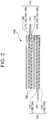
- FIG. 2 is a sectional view showing a positive electrode sheet 140, a negative electrode sheet 150, and separators 160 that constitute the electrode body 110. All of the positive electrode sheet 140, the negative electrode sheet 150, and the separators 160 have an elongated sheet shape in a depth direction of FIG. 2 .
- the electrode body 110 is obtained by laminating the positive electrode sheet 140, the negative electrode sheet 150, and the separators 160 as shown in FIG. 2 and winding the obtained laminate in a flat shape in a winding axial direction which is a left-right direction in FIG. 2 .
- a positive electrode active material layer 142 is formed on both surfaces of a positive electrode current collector foil 141.
- a positive electrode current collector foil 141 an aluminum foil can be used.
- the positive electrode active material layer 142 according to the embodiment includes a positive electrode active material 170, a conductive additive 180, a binder 145, and trilithium phosphate (Li 3 PO 4 ) 146.
- the positive electrode active material 170 is a material contributing to the charging and discharging of the battery 100 and can store and release lithium ions.
- the conductive additive 180 is a material which can improve the conductivity of the positive electrode active material layer 142.
- the binder 145 binds the materials, which are included in the positive electrode active material layer 142, to each other to form the positive electrode active material layer 142, and can also bind the positive electrode active material layer 142 to a surface of the positive electrode current collector foil 141.
- As the binder 145 for example, polyvinylidene fluoride (PVDF) can be used.
- PVDF polyvinylidene fluoride
- the trilithium phosphate 146 is an additive capable of forming a protective film on a surface of the positive electrode active material 170 .
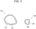
- FIG. 3 is a sectional view showing the positive electrode active material 170 and the conductive additive 180 of the battery 100 according to the embodiment.
- a positive electrode active material film 172 is formed on a surface of a positive electrode active material base 171.
- a composite oxide including at least lithium (Li) and manganese (Mn) can be used.
- the positive electrode active material base 171 is obtained by substituting a part of manganese (Mn) in lithium manganese oxide (LiMn 2 O 4 ) having a spinel-type crystal structure with a transition metal. That is, in the embodiment, LiNi 1/2 Mn 3/2 O 4 is used as the positive electrode active material 170. In LiNi 1/2 Mn 3/2 O 4 , the upper limit of the action potential vs. lithium metal (Li) is 4.75 V.
- the positive electrode active material film 172 includes at least fluorine (F), manganese (Mn), and phosphorus (P).
- the positive electrode active material film 172 is a film derived from the trilithium phosphate 146.
- a conductive additive film 182 is formed on a surface of a conductive additive base 181.
- a carbon material is used as the conductive additive base 181.
- carbon black such as acetylene black (AB), Ketjen black, furnace black, or channel black can be used.
- AB is used as the conductive additive base 181.
- the conductive additive film 182 includes at least fluorine (F), manganese (Mn), and phosphorus (P).
- the conductive additive film 182 is a film derived from the trilithium phosphate 146. The positive electrode active material film 172 and the conductive additive film 182 will be described below in detail.
- a negative electrode active material layer 152 is formed on both surfaces of a negative electrode current collector foil 151.
- a copper foil can be used as the negative electrode current collector foil 151.
- the negative electrode active material layer 152 according to the embodiment includes a negative electrode active material 155 and a binder 156.
- the negative electrode active material 155 is a material contributing to the charging and discharging of the battery 100 and can store and release lithium ions.
- As the negative electrode active material 155 for example, natural graphite can be used.
- the binder 156 binds the materials, which are included in the negative electrode active material layer 152, to each other to form the negative electrode active material layer 152, and can also bind the negative electrode active material layer 152 to a surface of the negative electrode current collector foil 151.
- the binder 156 for example, styrene-butadiene rubber (SBR) can be used.
- the separator 160 is a porous sheet having plural pores.
- the separator 160 for example, polypropylene (PP) or polyethylene (PE) can be used alone, or a composite material in which plural materials among the above materials are laminated can be used.
- the positive electrode sheet 140 has a portion where the positive electrode current collector foil 141 is exposed without the positive electrode active material layer 142 being formed.
- the negative electrode sheet 150 has a portion where the negative electrode current collector foil 151 is exposed without the negative electrode active material layer 152 being formed.
- a right end portion consists of only the exposure portion of the positive electrode sheet 140 where the positive electrode current collector foil 141 is exposed.
- a left end portion consists of only the exposure portion of the negative electrode sheet 150 where the negative electrode current collector foil 151 is exposed.
- a positive electrode terminal 149 is connected to the right end portion consisting of the exposure portion of the positive electrode current collector foil 141 of the electrode body 110.
- a negative electrode terminal 159 is connected to the left end portion consisting of the exposure portion of the negative electrode current collector foil 151 of the electrode body 110. Respective ends of the positive electrode terminal 149 and the negative electrode terminal 159 which are not connected to the electrode body 110 protrude to the outside of the battery case 130 through the insulating member 133.
- a portion of the positive electrode sheet 140 where the positive electrode active material layer 142 is formed and a portion of the negative electrode sheet 150 where the negative electrode active material layer 152 is formed are laminated with the separators 160 interposed therebetween as shown in FIG. 2 .
- the battery 100 is charged and discharged at the center of the electrode body 110 through the positive electrode terminal 149 and the negative electrode terminal 159.
- FIG. 4 shows the manufacturing procedure of the battery 100 according to the embodiment.
- the battery 100 is manufactured through a positive electrode sheet manufacturing step (S101), an accommodation step (S102), and an initial charging step (S103).
- the positive electrode sheet manufacturing step (S101) will be described in detail.
- the positive electrode sheet 140 is prepared by forming the positive electrode active material layer 142 on a surface of the positive electrode current collector foil 141.
- a positive electrode paste is used to form the positive electrode active material layer 142.
- the positive electrode paste is manufactured by dispersing the positive electrode active material 170, the conductive additive 180, the binder 145, and the trilithium phosphate 146, which are positive electrode materials constituting the positive electrode active material layer 142, in a solvent.
- NMP N-methylpyrrolidone
- the positive electrode paste is manufactured by putting the positive electrode materials and the solvent into a disperser and dispersing the components.
- the positive electrode active material film 172 is not formed on the positive electrode active material 170.
- the positive electrode active material base 171 is used as the positive electrode active material 170. That is, LiNi 1/2 Mn 3/2 O 4 , which is a composite oxide including at least lithium and manganese, is put into the disperser for manufacturing the positive electrode paste.
- the conductive additive film 182 is not formed on the conductive additive 180.
- the conductive additive 180 is obtained by attaching at least one of manganese (Mn) or manganese oxide to a surface of the conductive additive base 181.
- the conductive additive 180 is obtained by attaching manganese oxide 185 to a surface of the conductive additive base 181.
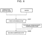
- the conductive additive 180 is manufactured by performing a conductive additive manufacturing step ( FIG. 6 ) in advance before the positive electrode sheet manufacturing step.
- FIG. 6 shows the procedure of the conductive additive manufacturing step for preparing the conductive additive 180 used for the positive electrode paste.
- the conductive additive 180 used for the positive electrode paste is manufactured through a first dispersion step (S201) and a second dispersion step (S202).
- the conductive additive base 181 and water are put into a disperser such that the conductive additive base 181 is dispersed in water.
- the conductive additive base 181 used herein is AB having a surface on which the manganese oxide 185 or the conductive additive film 182 is not attached.
- a potassium permanganate aqueous solution (KMnO 4 ) is put into the disperser, and the second dispersion step (S202) is performed.
- the second dispersion step manganese dioxide (MnO 2 ) is deposited on a surface of the conductive additive base 181 due to a reduction reaction in the potassium permanganate aqueous solution.
- the first dispersion step and the second dispersion step are performed together with irradiation of ultrasonic waves.
- the irradiation of ultrasonic waves accelerates the reduction reaction in the potassium permanganate aqueous solution, which accelerates the deposition of the manganese oxide 185 on the surface of the conductive additive base 181.
- the conductive additive 180 By removing a liquid component after the second dispersion step, the conductive additive 180 can be obtained in which manganese dioxide which is the manganese oxide 185 is attached to the surface of the conductive additive base 181.
- the liquid component can be removed by extracting the conductive additive 180, which is a solid component, after the second dispersion step and drying the extracted conductive additive 180. Accordingly, through the conductive additive manufacturing step shown in FIG. 6 , the conductive additive 180 ( FIG. 5 ) which is obtained by attaching the manganese oxide 185 to the surface of the conductive additive base 181 can be prepared.
- the positive electrode paste can be manufactured by dispersing the positive electrode active material 170 and the conductive additive 180 together with the binder 145 and the trilithium phosphate 146 in the solvent.
- the viscosity of the positive electrode paste is adjusted to 2.5 Pa ⁇ s or higher.
- the positive electrode active material layer 142 is formed by applying the prepared positive electrode paste to a region of the surface of the positive electrode current collector foil 141 where the positive electrode active material layer 142 is formed and drying the applied positive electrode paste. That is, by drying the positive electrode paste, the respective materials, such as the positive electrode active material 170, which are included in the positive electrode paste, bind to each other through the binder 145, thereby forming the positive electrode active material layer 142. Through the binder 145, the positive electrode active material layer 142 binds to the surface of the positive electrode current collector foil 141. As a result, the positive electrode sheet 140 is prepared.
- the positive electrode active material layer 142 formed on the surface of the positive electrode current collector foil 141 is pressed in a thickness direction thereof.
- a small roll pressing machine can be used for the pressing. The pressing is performed to adjust the density of the positive electrode active material layer 142. In the embodiment, due to the pressing, the density of the positive electrode active material layer 142 is adjusted to a range of 2.2 g/cm 3 to 2.4 g/cm 3 .
- the accommodation step (S102) is performed after the positive electrode sheet manufacturing step (S101).
- the electrode body 110 is prepared. Specifically, the electrode body 110 is prepared by laminating the positive electrode sheet 140, which is manufactured in the positive electrode sheet manufacturing step, and the negative electrode sheet 150 with the separators 160 interposed therebetween and winding the obtained laminate in a flat shape.
- the negative electrode sheet 150 can be manufactured using a negative electrode paste which is formed of a material different from that of the positive electrode sheet 140. That is, the negative electrode paste can be prepared by dispersing the negative electrode active material 155 and the binder 156 in a solvent. In order to appropriately disperse the negative electrode active material 155 in the negative electrode paste, a dispersant may be added.
- the negative electrode active material layer 152 can be formed by applying the prepared negative electrode paste to the negative electrode current collector foil 151 and drying the applied negative electrode paste. As a result, the negative electrode sheet 150 can be prepared in which the negative electrode active material layer 152 is formed on a surface of the negative electrode current collector foil 151.
- the electrode body 110 is accommodated in the case body 131 through an opening.
- the positive electrode sheet 140 and the negative electrode sheet 150 are accommodated in the case body 131.
- the positive electrode terminal 149 and the negative electrode terminal 159 may be connected to the electrode body 110 before accommodating the electrode body 110 in the case body 131.
- the joining of the battery case 130 or the joining of the positive electrode terminal 149 and the electrode body 110 or the joining of the negative electrode terminals 159 and the electrode body 110 can be performed by welding or the like.
- the positive electrode active material layer 142 of the positive electrode sheet 140 includes the trilithium phosphate 146. That is, in the accommodation step according to the embodiment, the trilithium phosphate 146 is accommodated in the battery case 130 together with the positive electrode sheet 140.
- the electrolytic solution 120 is also accommodated in the battery case 130.
- the electrolytic solution 120 can be accommodated in the case body 131 through the opening, for example, before the joining of the battery case 130.
- a liquid injection hole may be provided to connect the inside and the outside of the battery case 130 to each other such that the electrolytic solution 120 can be injected into the battery case 130 through the liquid injection hole. After the injection of the electrolytic solution 120, the liquid injection hole may be sealed. Accordingly, in the accommodation step, the battery 100 can be constructed.
- the initial charging step (S103) is performed.
- initial charging is performed in which the battery 100 constructed in the accommodation step is initially charged.
- constant-current (CC) charging is performed until the charge capacity of the battery 100 is fully charged, and thus the stage-of-charge (SOC) is adjusted to 100%.
- the battery 100 can be manufactured by performing the initial charging step.
- an aging treatment may be performed.
- an inspection step may be performed.
- LiNi 1/2 Mn 3/2 O 4 is used in which the upper limit of the action potential vs. lithium metal is high at 4.1 V or higher.
- the upper limit of the action potential vs. lithium metal is 4.75 V. Therefore, in the initial charging step, the battery voltage of the battery 100 is 4.1 V to 4.75 V.
- the solvent component in the electrolytic solution 120 is likely to be oxidized and decomposed on the surface of the positive electrode active material 170 in the positive electrode active material layer 142 in which the potential is increased to be 4.1 V or higher.
- hydrogen ions are produced. Further, the produced hydrogen ions react with fluorine ions in the electrolytic solution 120 to produce hydrofluoric acid (HF).
- the conductive additive 180 which is present near the positive electrode active material 170 in the positive electrode active material layer 142, has the same potential as that of the positive electrode active material 170. Therefore, it is presumed that, on the surface of the conductive additive 180, the oxidative decomposition of the solvent component of the electrolytic solution 120 occurs due to the positive electrode potential. That is, in the initial charging step, hydrofluoric acid is produced near the surface of the positive electrode active material 170 and the surface of the conductive additive 180 in the positive electrode active material layer 142.
- Hydrofluoric acid produced in the initial charging step reacts with the trilithium phosphate 146 included in the positive electrode active material layer 142. That is, the trilithium phosphate 146 is dissolved by reacting with hydrofluoric acid. Further, the produced hydrofluoric acid also reacts with the positive electrode active material 170. That is, manganese ions included in the positive electrode active material 170 are eluted therefrom due to the reaction with the hydrofluoric acid.
- the manganese ions eluted from the positive electrode active material 170 bind to the dissolved trilithium phosphate 146 and are deposited on the surface of the positive electrode active material 170. As a result, the positive electrode active material film 172 is formed on the surface of the positive electrode active material 170.
- the hydrofluoric acid produced in the initial charging step also reacts with the manganese oxide 185 attached to the surface to the conductive additive 180. That is, manganese ions included in the manganese oxide 185, which is attached to the surface of the conductive additive 180, are eluted therefrom due to the reaction with the hydrofluoric acid.
- the manganese ions eluted from the manganese oxide 185 of the conductive additive 180 bind to the dissolved trilithium phosphate 146 and are deposited on the surface of conductive additive 180.
- the conductive additive film 182 is formed on the surface of the conductive additive 180.
- the positive electrode active material 170 and the conductive additive 180 are changed from the state shown in FIG. 5 to the state shown in FIG. 3 .
- the oxidative decomposition of the solvent component of the electrolytic solution 120 is prevented on the surface of the positive electrode active material 170 on which the positive electrode active material film 172 is formed.
- the oxidative decomposition of the solvent component of the electrolytic solution 120 is prevented on the surface of the conductive additive 180 on which the conductive additive film 182 is formed.
- the production of hydrofluoric acid is prevented, and thus the deterioration of the battery 100 caused by hydrofluoric acid is prevented.
- a transition metal may be eluted from the positive electrode active material 170.
- the binder 145 included in the positive electrode active material layer 142, or the binder 156 included in the negative electrode active material layer 152 may be modified.
- the internal resistance of the battery 100 increases.
- the hydrofluoric acid closes the pores of the separators 160, which increases the internal resistance of the battery 100.
- the production of hydrofluoric acid is prevented, and thus the above-described deterioration is prevented.
- the present inventors verified that, in a case where the conductive additive base is used as the conductive additive in the positive electrode sheet manufacturing step by using LiNi 1/2 Mn 3/2 O 4 as the positive electrode active material, the conductive additive film is not formed on the surface of the conductive additive in the initial charging step. That is, in a case where LiNi 1/2 Mn 3/2 O 4 is used as the positive electrode active material, as described above, manganese ions are eluted from the positive electrode active material in the initial charging step. However, it was verified that the conductive additive film is not formed on the surface of the conductive additive by the manganese ions eluted from the positive electrode active material. That is, it was verified that, in the conductive additive 180 of the battery 100 used in the positive electrode sheet manufacturing step, the conductive additive film 182 is formed on the surface of the conductive additive base 181 by attaching the manganese oxide 185 thereto.
- the present inventors analyzed components constituting the positive electrode active material film 172 and components constituting the conductive additive film 182. Specifically, first, the positive electrode sheet 140 was extracted from the battery 100 after the initial charging step, and then the positive electrode sheet 140 was washed with a mixed organic solvent of EC and EMC. As a result, the electrolyte 122 was removed from the positive electrode sheet 140. Next, the positive electrode sheet 140 from which the electrolyte 122 was removed was dipped in a mixed solution of water and acetonitrile such that the positive electrode active material film 172 and the conductive additive film 182 were eluted from the positive electrode active material layer 142. Next, the solution in which the positive electrode active material film 172 and the conductive additive film 182 were eluted underwent an analysis using ion chromatography (IC analysis) and an analysis using inductively coupled plasma (ICP-MS analysis).
- IC analysis ion chromatography
- ICP-MS analysis inductively coupled plasma
- the present inventors performed a first experiment and a second experiment described below.
- batteries of Examples 1 to 4 according to the invention and a battery of Comparative Example for comparison with Examples 1 to 4 were prepared and used.
- Examples were different from Comparative Example, in that manganese oxide was attached to the surface of the conductive additive used in the positive electrode sheet manufacturing step.
- Comparative Example in the positive electrode sheet manufacturing step, the conductive additive base having a surface to which neither manganese nor manganese oxide were attached was used.
- the conductive additive base used in the positive electrode sheet manufacturing step according to Comparative Example is the same as the conductive additive base which was used in the conductive additive manufacturing step according to Examples before manganese oxide was formed.
- the battery according to Comparative Example is the same as the battery 100 described above, except for the conductive additive used in the positive electrode sheet manufacturing step.
- Table 1 shows the molar concentrations of the potassium permanganate aqueous solutions used in the conductive additive manufacturing step according to Examples and the composition ratios of manganese to carbon in the conductive additives prepared in the conductive additive manufacturing step.
- Each of the molar concentrations of the potassium permanganate aqueous solutions shown in Table 1 refers to the total molar concentration of water used in the first dispersion step and the potassium permanganate aqueous solution used in the second dispersion step.
- the molar concentrations of the potassium permanganate aqueous solutions used in the conductive additive manufacturing step were different from each other. Specifically, the molar concentration of the potassium permanganate aqueous solution used in the conductive additive manufacturing step increases in order from Example 1 to Example 4.
- the composition ratio (atomic ratio) of manganese to carbon shown in "Mn/C Ratio" of Table 1 increases in order from Example 1 to Example 4.
- the batteries according to the Examples and Comparative Example prepared under the above-described conditions were repeatedly charged and discharged in a cycle test, and the amounts of gas produced in the cycle test were compared to each other.
- the charging and the discharging were alternately performed 200 times at a constant current value of 1 C.
- the charge end voltage was set as 4.75 V
- the discharge end voltage was set as 3.5 V.
- the amount of gas produced in the cycle test was obtained based on the Archimedes principle by measuring the weight of the battery before the cycle test and the weight of the battery after the cycle test in a state of being dipped in the same amount of FLUORINERT (registered trade name), respectively, and obtaining a difference between the weight before the cycle test and the weight after the cycle test.
- FIG. 7 shows the gas production amount ratio acquired in each of the batteries according to Examples and Comparative Example in the first experiment.
- the gas production amount ratio refers to the ratio of the amount of gas, which was produced in each of the batteries according to Examples and Comparative Example, to the amount of gas produced in the battery according to Comparative Example. It can be seen from the results of the first experiment shown in FIG. 7 that, in all of Examples 1 to 4, the amount of gas produced was reduced to be less than that of Comparative Example.
- the positive electrode active material film was formed on the positive electrode active material, but the conductive additive film was not formed on the conductive additive.
- the reason for this is as follows.
- the oxidative decomposition of the electrolytic solution on the surface of the positive electrode active material was able to be prevented, but the oxidative decomposition of the electrolytic solution on the surface of the conductive additive was not able to be prevented. Therefore, it is presumed that, in the battery according to Comparative Example, the oxidative decomposition of the electrolytic solution in the cycle test was not appropriately prevented and that a large amount of gas was produced due to the oxidative decomposition of the electrolytic solution.
- the positive electrode active material film was formed on the positive electrode active material, and the conductive additive film was formed on the conductive additive.
- the reason for this is as follows.
- manganese oxide was attached to the surface of the conductive additive base. Accordingly, in all the batteries according to Examples 1 to 4, the oxidative decomposition of the electrolytic solution on the surface of the positive electrode active material and the oxidative decomposition of the electrolytic solution on the surface of the conductive additive were appropriately prevented. Therefore, it is presumed that, in all the batteries according to Examples 1 to 4, the amount of gas produced due to the oxidative decomposition of the electrolytic solution in the cycle test was reduced to be less than that of the battery according to Comparative Example.
- FIG. 8 shows the capacity retention acquired in each of the batteries according to Examples and Comparative Example in the second experiment.
- the capacity retention was lower than that of Comparative Example.
- the composition ratio of manganese to carbon in the conductive additive used in the positive electrode sheet manufacturing step was high. Therefore, it is presumed that, in Examples 3 and 4, the amount of manganese of the manganese oxide on the surface of the conductive additive was larger than the amount of manganese contributing to the formation of the conductive additive film in the initial charging step.
- the method of manufacturing the nonaqueous electrolyte secondary battery 100 includes the positive electrode sheet manufacturing step, the accommodation step, and the initial charging step.
- the positive electrode active material 170 is a composite oxide (LiNi 1/2 Mn 3/2 O 4 ) including at least lithium and manganese.
- the conductive additive 180 is obtained by attaching the manganese oxide 185 (manganese dioxide) to the surface of the conductive additive base 181 (carbon material).
- One of the materials constituting the positive electrode active material layer 142 of the positive electrode sheet 140 is the trilithium phosphate 146.
- the trilithium phosphate 146 is accommodated in the battery case 130 together with the positive electrode sheet 140.
- the positive electrode active material film 172 can be formed on the surface of the positive electrode active material 170
- the conductive additive film 182 can be formed on the surface of the conductive additive 180.
- the positive electrode active material film 172 and the conductive additive film 182 include at least fluorine, manganese, and phosphorus.
- the positive electrode active material film 172 and the conductive additive film 182 can prevent the oxidative decomposition of the electrolytic solution 120 on the surfaces of the positive electrode active material 170 and the conductive additive 180. That is, a nonaqueous electrolyte secondary battery and a method of manufacturing a nonaqueous electrolyte secondary battery can be realized, in which the oxidative decomposition of a nonaqueous electrolytic solution is prevented.
- the embodiment is merely exemplary and does not limit the invention. Accordingly, the invention can be improved and modified in various ways within a range not departing from the scope of the invention.
- the shape of the wound electrode body 110 is not limited to a flat shape, but a wound electrode body having a cylindrical shape can also be used.
- the invention can be applied not only a wound electrode body but also a laminate electrode body.
- the conductive additive 180 used in the positive electrode sheet manufacturing step can be manufactured by dispersing the conductive additive base 181 in the potassium permanganate aqueous solution so as to attach the manganese oxide 185 to the conductive additive base 181 in the conductive additive manufacturing step. That is, in the conductive additive manufacturing step according to the above-described embodiment, the manganese oxide is attached to the surface of the carbon material through the deposition caused by the reduction reaction of permanganate in the solution. However, the manganese oxide may be attached to the surface of the carbon material through the deposition caused by the reduction reaction of a manganate, instead of the permanganate, in the solution.
- manganese oxide As another method of attaching the manganese oxide to the surface of the carbon material, for example, powder sputtering can be adopted in which manganese oxide is used as a target and in which a carbon material is used as a substrate. As still another method of attaching manganese oxide to the surface of the carbon material, a mechanochemical method can be adopted.
- the example in which the manganese oxide 185, which is attached to the surface of the conductive additive 180 used in the positive electrode sheet manufacturing step, is manganese dioxide (MnO 2 ) has been described in detail.
- the manganese oxide, which is attached to the surface of the conductive additive used in the positive electrode sheet manufacturing step may be Mn 2 O 3 or Mn 3 O 4 instead of MnO 2 .
- manganese (Mn) may be attached to the surface of the carbon material. That is, the conductive additive used in the positive electrode sheet manufacturing step may be obtained by attaching at least one of manganese or manganese oxide to a surface of a carbon material.
- one of the materials constituting the positive electrode active material layer 142 of the positive electrode sheet 140 is the trilithium phosphate 146.
- the trilithium phosphate 146 is accommodated in the battery case 130 together with the positive electrode sheet 140.
- the trilithium phosphate may be accommodated in the battery case together with the electrolytic solution. That is, by using a solution in which trilithium phosphate is dissolved as the electrolytic solution, in the accommodation step, the trilithium phosphate may be accommodated in the battery case together with the electrolytic solution.
- the positive electrode active material film can be formed on the surface of the positive electrode active material, and the conductive additive film can be formed on the surface of the conductive additive.
Abstract
Description
- The present invention relates to a nonaqueous electrolyte secondary battery and a method of manufacturing a nonaqueous electrolyte secondary battery.
- When a lithium ion secondary battery is charged and discharged, oxidative decomposition of a nonaqueous electrolytic solution may occur. In a lithium ion secondary battery in which an acid is produced by the oxidative decomposition of a nonaqueous electrolytic solution, a transition metal may be eluted from a positive electrode active material due to the acid. In a case where a transition metal is eluted from a positive electrode active material, the capacity retention of a lithium ion secondary battery may decrease.
- For example, Japanese Patent Application Publication No.
2014-103098 JP 2014-103098 A JP 2014-103098 A - Here, in a case where a positive electrode active material layer includes trilithium phosphate, a film derived from trilithium phosphate is formed on a surface of a positive electrode active material in an initial charging step of a lithium ion secondary battery. On the surface of the positive electrode active material on which the film derived from trilithium phosphate is formed, the oxidative decomposition of a nonaqueous electrolytic solution is prevented. That is, by forming the film derived from trilithium phosphate on the surface of the positive electrode active material, the production of hydrofluoric acid on the surface of the positive electrode active material can be prevented.
- In general, in order to improve the conductivity of a positive electrode active material layer, the positive electrode active material layer includes a conductive additive. It was found that, in a lithium ion secondary battery in which a positive electrode active material layer includes a conductive additive, the oxidative decomposition of a nonaqueous electrolytic solution may also occur on a surface of the conductive additive. Hydrofluoric acid is also produced due to the oxidative decomposition of the nonaqueous electrolytic solution on the surface of the conductive additive.
- The invention provides a nonaqueous electrolyte secondary battery and a method of manufacturing a nonaqueous electrolyte secondary battery, in which the oxidative decomposition of a nonaqueous electrolytic solution can be prevented.
- According to a first aspect of the invention, there is provided a nonaqueous electrolyte secondary battery including: a positive electrode sheet; a negative electrode sheet; a nonaqueous electrolytic solution that includes an ionic compound including fluorine; and a battery case that accommodates the positive electrode sheet, the negative electrode sheet, and the electrolytic solution. In the nonaqueous electrolyte secondary battery according to the first aspect of the invention, the positive electrode sheet includes a positive electrode current collector foil and a positive electrode active material layer that includes a positive electrode active material and a conductive additive. The positive electrode active material has a first film formed on a surface of the composite oxide including at least lithium and manganese. The conductive additive has a second film formed on a surface of the carbon material. The first film and the second film include at least fluorine, manganese, and phosphorus.
- According to the first aspect of the invention, the first film is formed on the positive electrode active material. Therefore, the oxidative decomposition of the nonaqueous electrolytic solution on the surface of the positive electrode active material is prevented. In addition, the second film is formed on the conductive additive. Therefore, the oxidative decomposition of the nonaqueous electrolytic solution on the surface of the conductive additive is prevented. As a result, in the nonaqueous electrolyte secondary battery according to the first aspect of the invention, the oxidative decomposition of the nonaqueous electrolytic solution is prevented.
- According to a second aspect of the invention, there is provided a method of manufacturing a nonaqueous electrolyte secondary battery, the nonaqueous electrolyte secondary battery including: a positive electrode sheet; a negative electrode sheet; a nonaqueous electrolytic solution that includes an ionic compound including fluorine; and a battery case that accommodates the positive electrode sheet, the negative electrode sheet, and the electrolytic solution. In the second aspect of the invention, the method includes: manufacturing the positive electrode sheet by forming a positive electrode active material layer, which includes a positive electrode active material, a conductive additive and trilithium phosphate, on a surface of a positive electrode current collector foil; accommodating the positive electrode sheet, a negative electrode sheet, and an electrolytic solution in a battery case; and charging a battery after the positive electrode sheet, the negative electrode sheet, the electrolytic solution, and the trilithium phosphate are accommodated. In the manufacturing of the positive electrode sheet, the positive electrode active material is a composite oxide including lithium and manganese, and the conductive additive is obtained by attaching at least one of manganese and manganese oxide to a surface of a carbon material.
- According to the second aspect of the invention, during the manufacturing of the positive electrode sheet, the positive electrode active material is a composite oxide including at least lithium and manganese. During the manufacturing of the positive electrode sheet, the conductive additive is obtained by attaching at least one of manganese or manganese oxide to a surface of a carbon material. When the battery is charged after the positive electrode sheet, the negative electrode sheet, the nonaqueous electrolytic solution, and the trilithium phosphate are accommodated, hydrofluoric acid is produced due to the oxidative decomposition of the nonaqueous electrolytic solution on the surface of the positive electrode active material and on the surface of the conductive additive. The hydrofluoric acid causes the dissolution of trilithium phosphate and the elution of manganese ions from the positive electrode active material. The manganese ions eluted from the positive electrode active material bind to the dissolved trilithium phosphate and are deposited on the surface of the positive electrode active material to form a film on the surface of the positive electrode active material. Further, the hydrofluoric acid causes the elution of manganese ions from at least one of manganese or manganese oxide attached to the surface of the conductive additive. The manganese ions eluted from at least one of manganese or manganese oxide of the conductive additive bind to the dissolved trilithium phosphate and are deposited on the surface of conductive additive to form a film on the surface of the conductive additive. Both the positive electrode active material on which the film is formed and the conductive additive on which the film is formed prevent the oxidative decomposition of the nonaqueous electrolytic solution on the surfaces thereof. That is, the oxidative decomposition of the nonaqueous electrolytic solution in the manufactured nonaqueous electrolyte secondary battery can be prevented.
- In the method of manufacturing a nonaqueous electrolyte secondary battery described above, an atomic ratio of manganese to carbon in the conductive additive may be 0.05 or higher. The reason for this is that, with the above-described configuration, the film formed on the surface of the conductive additive can sufficiently prevent the oxidative decomposition of the nonaqueous electrolytic solution on the surface of the conductive additive.
- In the method of manufacturing a nonaqueous electrolyte secondary battery described above, an atomic ratio of manganese to carbon in the conductive additive may be 0.10 or lower. The reason for this is as follows. In a case where the atomic ratio of manganese to carbon in the conductive additive is excessively high, manganese ions, which do not contribute to the formation of the film of the conductive additive among the manganese ions eluted from the surface of the conductive additive, may be deposited on the negative electrode sheet. The deposition of manganese on the negative electrode sheet may cause a decrease in the charge capacity of the nonaqueous electrolyte secondary battery. Accordingly, by using the conductive additive in which the atomic ratio of manganese to carbon is 0.10 or lower, the deposition of manganese on the negative electrode sheet is prevented, and a decrease in the charge capacity of the nonaqueous electrolyte secondary battery can be prevented.
- According to the present invention, there are provided a nonaqueous electrolyte secondary battery and a method of manufacturing a nonaqueous electrolyte secondary battery, in which the oxidative decomposition of a nonaqueous electrolytic solution can be prevented.
- Features, advantages, and technical and industrial significance of exemplary embodiments of the invention will be described below with reference to the accompanying drawings, in which like numerals denote like elements, and wherein:
-
FIG. 1 is a sectional view showing a battery according to an embodiment of the invention; -
FIG. 2 is a sectional view showing a positive electrode sheet, a negative electrode sheet, and separators of the battery according to the embodiment; -
FIG. 3 is a sectional view showing a positive electrode active material and a conductive additive of the battery according to the embodiment; -
FIG. 4 is a diagram showing the manufacturing procedure of the battery according to the embodiment; -
FIG. 5 is a sectional view showing a positive electrode active material and a conductive additive used in a positive electrode sheet manufacturing step according to the embodiment; -
FIG. 6 is a diagram showing the manufacturing procedure of the conductive additive used in the positive electrode sheet manufacturing step according to the embodiment; -
FIG. 7 is a diagram showing gas production amount ratios of batteries according to Examples and Comparative Example; and -
FIG. 8 is a diagram showing capacity retentions of batteries according to Examples and Comparative Example. - Hereinafter, an embodiment of the invention will be described in detail with reference to the drawings.
- First, a battery 100 (refer to
FIG. 1 ) according to the embodiment will be described.FIG. 1 shows a sectional view showing thebattery 100 according to the embodiment. As shown inFIG. 1 , thebattery 100 is a lithium ion secondary battery in which anelectrode body 110 and an electrolytic solution 120 are accommodated in abattery case 130. Thebattery case 130 includes acase body 131 and asealing plate 132. The sealingplate 132 includes an insulatingmember 133. - The electrolytic solution 120 according to the embodiment is a nonaqueous electrolytic solution in which an electrolyte 122 is dissolved in a nonaqueous solvent 121. Specifically, in the electrolytic solution 120 according to the embodiment, as the nonaqueous solvent 121, a mixed organic solvent is used in which ethylene carbonate (EC) and ethyl methyl carbonate (EMC) which are organic solvents are mixed with each other. As the electrolytic solution 120, for example, dimethyl carbonate (DMC) which is another organic solvent can be used.
- In the electrolytic solution 120 according to the embodiment, as the electrolyte 122, lithium hexafluorophosphate (LiPF6) which is an ionic compound including fluorine is used. That is, the electrolytic solution 120 is a nonaqueous electrolytic solution that includes an ionic compound including fluorine. As the electrolyte 122, for example, LiPF6, LiBF4, LiAsF6, LiCF3SO3, LiC4F9SO3, LiN(CF3SO2)2, or LiC(CF3SO2)3 can be used.
-
FIG. 2 is a sectional view showing apositive electrode sheet 140, anegative electrode sheet 150, andseparators 160 that constitute theelectrode body 110. All of thepositive electrode sheet 140, thenegative electrode sheet 150, and theseparators 160 have an elongated sheet shape in a depth direction ofFIG. 2 . Theelectrode body 110 is obtained by laminating thepositive electrode sheet 140, thenegative electrode sheet 150, and theseparators 160 as shown inFIG. 2 and winding the obtained laminate in a flat shape in a winding axial direction which is a left-right direction inFIG. 2 . - As shown in
FIG. 2 , in thepositive electrode sheet 140, a positive electrodeactive material layer 142 is formed on both surfaces of a positive electrodecurrent collector foil 141. As the positive electrodecurrent collector foil 141, an aluminum foil can be used. The positive electrodeactive material layer 142 according to the embodiment includes a positive electrodeactive material 170, aconductive additive 180, a binder 145, and trilithium phosphate (Li3PO4) 146. - The positive electrode
active material 170 is a material contributing to the charging and discharging of thebattery 100 and can store and release lithium ions. Theconductive additive 180 is a material which can improve the conductivity of the positive electrodeactive material layer 142. The binder 145 binds the materials, which are included in the positive electrodeactive material layer 142, to each other to form the positive electrodeactive material layer 142, and can also bind the positive electrodeactive material layer 142 to a surface of the positive electrodecurrent collector foil 141. As the binder 145, for example, polyvinylidene fluoride (PVDF) can be used. The trilithium phosphate 146 is an additive capable of forming a protective film on a surface of the positive electrodeactive material 170 . -
FIG. 3 is a sectional view showing the positive electrodeactive material 170 and theconductive additive 180 of thebattery 100 according to the embodiment. In the positive electrodeactive material 170, as shown inFIG. 3 , a positive electrodeactive material film 172 is formed on a surface of a positive electrodeactive material base 171. As the positive electrodeactive material base 171, a composite oxide including at least lithium (Li) and manganese (Mn) can be used. In the embodiment, specifically, the positive electrodeactive material base 171 is obtained by substituting a part of manganese (Mn) in lithium manganese oxide (LiMn2O4) having a spinel-type crystal structure with a transition metal. That is, in the embodiment, LiNi1/2Mn3/2O4 is used as the positive electrodeactive material 170. In LiNi1/2Mn3/2O4, the upper limit of the action potential vs. lithium metal (Li) is 4.75 V. - The positive electrode
active material film 172 includes at least fluorine (F), manganese (Mn), and phosphorus (P). The positive electrodeactive material film 172 is a film derived from the trilithium phosphate 146. - In the
conductive additive 180, as shown inFIG. 3 , aconductive additive film 182 is formed on a surface of aconductive additive base 181. In the embodiment, a carbon material is used as theconductive additive base 181. As the carbon material, for example, carbon black such as acetylene black (AB), Ketjen black, furnace black, or channel black can be used. In the embodiment, specifically, AB is used as theconductive additive base 181. - As in the case of the positive electrode
active material film 172, theconductive additive film 182 includes at least fluorine (F), manganese (Mn), and phosphorus (P). As in the case of the positive electrodeactive material film 172, theconductive additive film 182 is a film derived from the trilithium phosphate 146. The positive electrodeactive material film 172 and theconductive additive film 182 will be described below in detail. - As shown in
FIG. 2 , in thenegative electrode sheet 150, a negative electrodeactive material layer 152 is formed on both surfaces of a negative electrodecurrent collector foil 151. As the negative electrodecurrent collector foil 151, a copper foil can be used. The negative electrodeactive material layer 152 according to the embodiment includes a negative electrode active material 155 and a binder 156. - The negative electrode active material 155 is a material contributing to the charging and discharging of the
battery 100 and can store and release lithium ions. As the negative electrode active material 155, for example, natural graphite can be used. The binder 156 binds the materials, which are included in the negative electrodeactive material layer 152, to each other to form the negative electrodeactive material layer 152, and can also bind the negative electrodeactive material layer 152 to a surface of the negative electrodecurrent collector foil 151. As the binder 156, for example, styrene-butadiene rubber (SBR) can be used. - The
separator 160 is a porous sheet having plural pores. As theseparator 160, for example, polypropylene (PP) or polyethylene (PE) can be used alone, or a composite material in which plural materials among the above materials are laminated can be used. - As shown in
FIG. 2 , thepositive electrode sheet 140 has a portion where the positive electrodecurrent collector foil 141 is exposed without the positive electrodeactive material layer 142 being formed. Thenegative electrode sheet 150 has a portion where the negative electrodecurrent collector foil 151 is exposed without the negative electrodeactive material layer 152 being formed. In thewound electrode body 110 shown inFIG. 1 , a right end portion consists of only the exposure portion of thepositive electrode sheet 140 where the positive electrodecurrent collector foil 141 is exposed. In thewound electrode body 110 shown inFIG. 1 , a left end portion consists of only the exposure portion of thenegative electrode sheet 150 where the negative electrodecurrent collector foil 151 is exposed. - Further, as shown in
FIG. 1 , apositive electrode terminal 149 is connected to the right end portion consisting of the exposure portion of the positive electrodecurrent collector foil 141 of theelectrode body 110. Anegative electrode terminal 159 is connected to the left end portion consisting of the exposure portion of the negative electrodecurrent collector foil 151 of theelectrode body 110. Respective ends of thepositive electrode terminal 149 and thenegative electrode terminal 159 which are not connected to theelectrode body 110 protrude to the outside of thebattery case 130 through the insulatingmember 133. - On the other hand, at the center of the
electrode body 110 inFIG. 1 , a portion of thepositive electrode sheet 140 where the positive electrodeactive material layer 142 is formed and a portion of thenegative electrode sheet 150 where the negative electrodeactive material layer 152 is formed are laminated with theseparators 160 interposed therebetween as shown inFIG. 2 . Thebattery 100 is charged and discharged at the center of theelectrode body 110 through thepositive electrode terminal 149 and thenegative electrode terminal 159. - Next, a method of manufacturing the
battery 100 according to the embodiment will be described.FIG. 4 shows the manufacturing procedure of thebattery 100 according to the embodiment. As shown inFIG. 4 , in the embodiment, thebattery 100 is manufactured through a positive electrode sheet manufacturing step (S101), an accommodation step (S102), and an initial charging step (S103). - First, the positive electrode sheet manufacturing step (S101) will be described in detail. In this step, the
positive electrode sheet 140 is prepared by forming the positive electrodeactive material layer 142 on a surface of the positive electrodecurrent collector foil 141. In the embodiment, a positive electrode paste is used to form the positive electrodeactive material layer 142. The positive electrode paste is manufactured by dispersing the positive electrodeactive material 170, theconductive additive 180, the binder 145, and the trilithium phosphate 146, which are positive electrode materials constituting the positive electrodeactive material layer 142, in a solvent. As the solvent of the positive electrode paste, N-methylpyrrolidone (NMP) can be used. In the embodiment, the positive electrode paste is manufactured by putting the positive electrode materials and the solvent into a disperser and dispersing the components. - Here, during the manufacturing of the positive electrode paste in the positive electrode sheet manufacturing step according to the embodiment, the positive electrode
active material film 172 is not formed on the positive electrodeactive material 170. Specifically, in the embodiment, as shown inFIG. 5 , only the positive electrodeactive material base 171 is used as the positive electrodeactive material 170. That is, LiNi1/2Mn3/2O4, which is a composite oxide including at least lithium and manganese, is put into the disperser for manufacturing the positive electrode paste. - Here, during the manufacturing of the positive electrode paste in the positive electrode sheet manufacturing step according to the embodiment, the
conductive additive film 182 is not formed on theconductive additive 180. Further, during the manufacturing of the positive electrode paste, theconductive additive 180 is obtained by attaching at least one of manganese (Mn) or manganese oxide to a surface of theconductive additive base 181. Specifically, in the embodiment, as shown inFIG. 5 , theconductive additive 180 is obtained by attachingmanganese oxide 185 to a surface of theconductive additive base 181. Theconductive additive 180 is manufactured by performing a conductive additive manufacturing step (FIG. 6 ) in advance before the positive electrode sheet manufacturing step. -
FIG. 6 shows the procedure of the conductive additive manufacturing step for preparing theconductive additive 180 used for the positive electrode paste. As shown inFIG. 6 , in the conductive additive manufacturing step according to the embodiment, theconductive additive 180 used for the positive electrode paste is manufactured through a first dispersion step (S201) and a second dispersion step (S202). - First, in the first dispersion step (S201), the
conductive additive base 181 and water are put into a disperser such that theconductive additive base 181 is dispersed in water. Theconductive additive base 181 used herein is AB having a surface on which themanganese oxide 185 or theconductive additive film 182 is not attached. - Next, a potassium permanganate aqueous solution (KMnO4) is put into the disperser, and the second dispersion step (S202) is performed. In the second dispersion step, manganese dioxide (MnO2) is deposited on a surface of the
conductive additive base 181 due to a reduction reaction in the potassium permanganate aqueous solution. In the embodiment, the first dispersion step and the second dispersion step are performed together with irradiation of ultrasonic waves. In the second dispersion step, the irradiation of ultrasonic waves accelerates the reduction reaction in the potassium permanganate aqueous solution, which accelerates the deposition of themanganese oxide 185 on the surface of theconductive additive base 181. - By removing a liquid component after the second dispersion step, the
conductive additive 180 can be obtained in which manganese dioxide which is themanganese oxide 185 is attached to the surface of theconductive additive base 181. The liquid component can be removed by extracting theconductive additive 180, which is a solid component, after the second dispersion step and drying the extractedconductive additive 180. Accordingly, through the conductive additive manufacturing step shown inFIG. 6 , the conductive additive 180 (FIG. 5 ) which is obtained by attaching themanganese oxide 185 to the surface of theconductive additive base 181 can be prepared. - The positive electrode paste can be manufactured by dispersing the positive electrode
active material 170 and theconductive additive 180 together with the binder 145 and the trilithium phosphate 146 in the solvent. In the embodiment, the viscosity of the positive electrode paste is adjusted to 2.5 Pa·s or higher. - Further, the positive electrode
active material layer 142 is formed by applying the prepared positive electrode paste to a region of the surface of the positive electrodecurrent collector foil 141 where the positive electrodeactive material layer 142 is formed and drying the applied positive electrode paste. That is, by drying the positive electrode paste, the respective materials, such as the positive electrodeactive material 170, which are included in the positive electrode paste, bind to each other through the binder 145, thereby forming the positive electrodeactive material layer 142. Through the binder 145, the positive electrodeactive material layer 142 binds to the surface of the positive electrodecurrent collector foil 141. As a result, thepositive electrode sheet 140 is prepared. - Further, in the positive electrode sheet manufacturing step according to the embodiment, the positive electrode
active material layer 142 formed on the surface of the positive electrodecurrent collector foil 141 is pressed in a thickness direction thereof. For the pressing, a small roll pressing machine can be used. The pressing is performed to adjust the density of the positive electrodeactive material layer 142. In the embodiment, due to the pressing, the density of the positive electrodeactive material layer 142 is adjusted to a range of 2.2 g/cm3 to 2.4 g/cm3. - As shown in
FIG. 4 , the accommodation step (S102) is performed after the positive electrode sheet manufacturing step (S101). In the accommodation step, first, theelectrode body 110 is prepared. Specifically, theelectrode body 110 is prepared by laminating thepositive electrode sheet 140, which is manufactured in the positive electrode sheet manufacturing step, and thenegative electrode sheet 150 with theseparators 160 interposed therebetween and winding the obtained laminate in a flat shape. - The
negative electrode sheet 150 can be manufactured using a negative electrode paste which is formed of a material different from that of thepositive electrode sheet 140. That is, the negative electrode paste can be prepared by dispersing the negative electrode active material 155 and the binder 156 in a solvent. In order to appropriately disperse the negative electrode active material 155 in the negative electrode paste, a dispersant may be added. The negative electrodeactive material layer 152 can be formed by applying the prepared negative electrode paste to the negative electrodecurrent collector foil 151 and drying the applied negative electrode paste. As a result, thenegative electrode sheet 150 can be prepared in which the negative electrodeactive material layer 152 is formed on a surface of the negative electrodecurrent collector foil 151. - Next, the
electrode body 110 is accommodated in thecase body 131 through an opening. As a result, thepositive electrode sheet 140 and thenegative electrode sheet 150 are accommodated in thecase body 131. By sealing the opening of thecase body 131 with the sealingplate 132, the components are joined to each other. Thepositive electrode terminal 149 and thenegative electrode terminal 159 may be connected to theelectrode body 110 before accommodating theelectrode body 110 in thecase body 131. The joining of thebattery case 130 or the joining of thepositive electrode terminal 149 and theelectrode body 110 or the joining of thenegative electrode terminals 159 and theelectrode body 110 can be performed by welding or the like. - The positive electrode
active material layer 142 of thepositive electrode sheet 140 includes the trilithium phosphate 146. That is, in the accommodation step according to the embodiment, the trilithium phosphate 146 is accommodated in thebattery case 130 together with thepositive electrode sheet 140. - Further, in the accommodation step, the electrolytic solution 120 is also accommodated in the
battery case 130. The electrolytic solution 120 can be accommodated in thecase body 131 through the opening, for example, before the joining of thebattery case 130. Alternatively, a liquid injection hole may be provided to connect the inside and the outside of thebattery case 130 to each other such that the electrolytic solution 120 can be injected into thebattery case 130 through the liquid injection hole. After the injection of the electrolytic solution 120, the liquid injection hole may be sealed. Accordingly, in the accommodation step, thebattery 100 can be constructed. - Next, as shown in
FIG. 4 , the initial charging step (S103) is performed. In this step, initial charging is performed in which thebattery 100 constructed in the accommodation step is initially charged. In the initial charging step according to the embodiment, constant-current (CC) charging is performed until the charge capacity of thebattery 100 is fully charged, and thus the stage-of-charge (SOC) is adjusted to 100%. In the embodiment, thebattery 100 can be manufactured by performing the initial charging step. - Regarding the
battery 100 which has undergone the accommodation step, appropriately, an aging treatment may be performed. In order to remove a defective product in the manufacturing steps, appropriately, an inspection step may be performed. - Here, in the embodiment, as the positive electrode
active material 170, LiNi1/2Mn3/2O4 is used in which the upper limit of the action potential vs. lithium metal is high at 4.1 V or higher. Specifically, in LiNi1/2Mn3/2O4 used in the embodiment, as described above, the upper limit of the action potential vs. lithium metal is 4.75 V. Therefore, in the initial charging step, the battery voltage of thebattery 100 is 4.1 V to 4.75 V. - The solvent component in the electrolytic solution 120 according to the embodiment is likely to be oxidized and decomposed on the surface of the positive electrode
active material 170 in the positive electrodeactive material layer 142 in which the potential is increased to be 4.1 V or higher. By the electrolytic solution 120 being oxidized and decomposed, hydrogen ions are produced. Further, the produced hydrogen ions react with fluorine ions in the electrolytic solution 120 to produce hydrofluoric acid (HF). - The
conductive additive 180, which is present near the positive electrodeactive material 170 in the positive electrodeactive material layer 142, has the same potential as that of the positive electrodeactive material 170. Therefore, it is presumed that, on the surface of theconductive additive 180, the oxidative decomposition of the solvent component of the electrolytic solution 120 occurs due to the positive electrode potential. That is, in the initial charging step, hydrofluoric acid is produced near the surface of the positive electrodeactive material 170 and the surface of theconductive additive 180 in the positive electrodeactive material layer 142. - Hydrofluoric acid produced in the initial charging step reacts with the trilithium phosphate 146 included in the positive electrode
active material layer 142. That is, the trilithium phosphate 146 is dissolved by reacting with hydrofluoric acid. Further, the produced hydrofluoric acid also reacts with the positive electrodeactive material 170. That is, manganese ions included in the positive electrodeactive material 170 are eluted therefrom due to the reaction with the hydrofluoric acid. - The manganese ions eluted from the positive electrode
active material 170 bind to the dissolved trilithium phosphate 146 and are deposited on the surface of the positive electrodeactive material 170. As a result, the positive electrodeactive material film 172 is formed on the surface of the positive electrodeactive material 170. - The hydrofluoric acid produced in the initial charging step also reacts with the
manganese oxide 185 attached to the surface to theconductive additive 180. That is, manganese ions included in themanganese oxide 185, which is attached to the surface of theconductive additive 180, are eluted therefrom due to the reaction with the hydrofluoric acid. The manganese ions eluted from themanganese oxide 185 of theconductive additive 180 bind to the dissolved trilithium phosphate 146 and are deposited on the surface ofconductive additive 180. As a result, theconductive additive film 182 is formed on the surface of theconductive additive 180. - That is, in the initial charging step, the positive electrode
active material 170 and theconductive additive 180 are changed from the state shown inFIG. 5 to the state shown inFIG. 3 . Next, the oxidative decomposition of the solvent component of the electrolytic solution 120 is prevented on the surface of the positive electrodeactive material 170 on which the positive electrodeactive material film 172 is formed. In addition, the oxidative decomposition of the solvent component of the electrolytic solution 120 is prevented on the surface of theconductive additive 180 on which theconductive additive film 182 is formed. - In the
battery 100 according to the embodiment, the production of hydrofluoric acid is prevented, and thus the deterioration of thebattery 100 caused by hydrofluoric acid is prevented. Specifically, in a case where hydrofluoric acid is produced in thebattery 100, a transition metal may be eluted from the positive electrodeactive material 170. In a case where hydrofluoric acid is produced in thebattery 100, the binder 145 included in the positive electrodeactive material layer 142, or the binder 156 included in the negative electrodeactive material layer 152 may be modified. For example, in a case where the binder 145 is modified and covers the positive electrodeactive material 170, the internal resistance of thebattery 100 increases. In a case where hydrofluoric acid is produced in thebattery 100, the hydrofluoric acid closes the pores of theseparators 160, which increases the internal resistance of thebattery 100. However, in thebattery 100 according to the embodiment, the production of hydrofluoric acid is prevented, and thus the above-described deterioration is prevented. - The present inventors verified that, in a case where the conductive additive base is used as the conductive additive in the positive electrode sheet manufacturing step by using LiNi1/2Mn3/2O4 as the positive electrode active material, the conductive additive film is not formed on the surface of the conductive additive in the initial charging step. That is, in a case where LiNi1/2Mn3/2O4 is used as the positive electrode active material, as described above, manganese ions are eluted from the positive electrode active material in the initial charging step. However, it was verified that the conductive additive film is not formed on the surface of the conductive additive by the manganese ions eluted from the positive electrode active material. That is, it was verified that, in the
conductive additive 180 of thebattery 100 used in the positive electrode sheet manufacturing step, theconductive additive film 182 is formed on the surface of theconductive additive base 181 by attaching themanganese oxide 185 thereto. - Further, the present inventors analyzed components constituting the positive electrode
active material film 172 and components constituting theconductive additive film 182. Specifically, first, thepositive electrode sheet 140 was extracted from thebattery 100 after the initial charging step, and then thepositive electrode sheet 140 was washed with a mixed organic solvent of EC and EMC. As a result, the electrolyte 122 was removed from thepositive electrode sheet 140. Next, thepositive electrode sheet 140 from which the electrolyte 122 was removed was dipped in a mixed solution of water and acetonitrile such that the positive electrodeactive material film 172 and theconductive additive film 182 were eluted from the positive electrodeactive material layer 142. Next, the solution in which the positive electrodeactive material film 172 and theconductive additive film 182 were eluted underwent an analysis using ion chromatography (IC analysis) and an analysis using inductively coupled plasma (ICP-MS analysis). - Through the IC analysis of the elution in which the positive electrode
active material film 172 and theconductive additive film 182 were eluted, fluorine ions (F-) and difluorophosphate ions (PO2F2 -) were able to be quantitatively and qualitatively analyzed. Through the ICP-MS analysis of the solution in which the positive electrodeactive material film 172 and theconductive additive film 182 were eluted, manganese ions (Mn2+) were able to be quantitatively and qualitatively analyzed. Accordingly, it was able to be verified from the results of the analysis that the positive electrodeactive material film 172 and theconductive additive film 182 include at least fluorine (F), manganese (Mn), and phosphorus (P). It is presumed that positive electrodeactive material film 172 and theconductive additive film 182 can be represented by MnxPO5FY (X and Y represent variables which vary depending on valences of manganese and phosphorus). - The present inventors performed a first experiment and a second experiment described below. In both the first and second experiments, batteries of Examples 1 to 4 according to the invention and a battery of Comparative Example for comparison with Examples 1 to 4 were prepared and used. Examples were different from Comparative Example, in that manganese oxide was attached to the surface of the conductive additive used in the positive electrode sheet manufacturing step.
- That is, in all of Examples 1 to 4, in the conductive additive used in the positive electrode sheet manufacturing step, manganese oxide was attached to the surface of the conductive additive base. That is, in the positive electrode sheet manufacturing step, the conductive additive was prepared according to the conductive additive manufacturing step shown in
FIG. 6 . That is, all of the batteries according to Examples 1 to 4 were thebatteries 100 described above. - On the other hand, in Comparative Example, in the positive electrode sheet manufacturing step, the conductive additive base having a surface to which neither manganese nor manganese oxide were attached was used. Specifically, the conductive additive base used in the positive electrode sheet manufacturing step according to Comparative Example is the same as the conductive additive base which was used in the conductive additive manufacturing step according to Examples before manganese oxide was formed. The battery according to Comparative Example is the same as the
battery 100 described above, except for the conductive additive used in the positive electrode sheet manufacturing step. - Table 1 below shows the molar concentrations of the potassium permanganate aqueous solutions used in the conductive additive manufacturing step according to Examples and the composition ratios of manganese to carbon in the conductive additives prepared in the conductive additive manufacturing step. Each of the molar concentrations of the potassium permanganate aqueous solutions shown in Table 1 refers to the total molar concentration of water used in the first dispersion step and the potassium permanganate aqueous solution used in the second dispersion step.
[Table 1] Molar Concentrations of KMnO4 Aqueous Solution [10-3 mol/L] Mn/C Ratio in Conductive Additive (Atomic Ratio) Example 1 2.5 0.05 Example 2 5.0 0.10 Example 3 7.0 0.15 Example 4 10.0 0.20 - As shown in Table 1, in Examples 1 to 4, the molar concentrations of the potassium permanganate aqueous solutions used in the conductive additive manufacturing step were different from each other. Specifically, the molar concentration of the potassium permanganate aqueous solution used in the conductive additive manufacturing step increases in order from Example 1 to Example 4. In the conductive additive prepared in the conductive additive manufacturing step, the composition ratio (atomic ratio) of manganese to carbon shown in "Mn/C Ratio" of Table 1 increases in order from Example 1 to Example 4.
- In the first experiment, the batteries according to the Examples and Comparative Example prepared under the above-described conditions were repeatedly charged and discharged in a cycle test, and the amounts of gas produced in the cycle test were compared to each other. In the cycle test, the charging and the discharging were alternately performed 200 times at a constant current value of 1 C. In the cycle test, the charge end voltage was set as 4.75 V, and the discharge end voltage was set as 3.5 V. The amount of gas produced in the cycle test was obtained based on the Archimedes principle by measuring the weight of the battery before the cycle test and the weight of the battery after the cycle test in a state of being dipped in the same amount of FLUORINERT (registered trade name), respectively, and obtaining a difference between the weight before the cycle test and the weight after the cycle test.
-
FIG. 7 shows the gas production amount ratio acquired in each of the batteries according to Examples and Comparative Example in the first experiment. The gas production amount ratio refers to the ratio of the amount of gas, which was produced in each of the batteries according to Examples and Comparative Example, to the amount of gas produced in the battery according to Comparative Example. It can be seen from the results of the first experiment shown inFIG. 7 that, in all of Examples 1 to 4, the amount of gas produced was reduced to be less than that of Comparative Example. - In the battery according to Comparative Example, the positive electrode active material film was formed on the positive electrode active material, but the conductive additive film was not formed on the conductive additive. The reason for this is as follows. In Comparative Example, in the conductive additive used in the positive electrode sheet manufacturing step, neither manganese nor manganese oxide were attached to the conductive additive base. Accordingly, in the cycle test of the battery according to Comparative Example, the oxidative decomposition of the electrolytic solution on the surface of the positive electrode active material was able to be prevented, but the oxidative decomposition of the electrolytic solution on the surface of the conductive additive was not able to be prevented. Therefore, it is presumed that, in the battery according to Comparative Example, the oxidative decomposition of the electrolytic solution in the cycle test was not appropriately prevented and that a large amount of gas was produced due to the oxidative decomposition of the electrolytic solution.
- On the other hand, in all the batteries according to Examples 1 to 4, the positive electrode active material film was formed on the positive electrode active material, and the conductive additive film was formed on the conductive additive. The reason for this is as follows. In all of Examples 1 to 4, in the conductive additive used in the positive electrode sheet manufacturing step, manganese oxide was attached to the surface of the conductive additive base. Accordingly, in all the batteries according to Examples 1 to 4, the oxidative decomposition of the electrolytic solution on the surface of the positive electrode active material and the oxidative decomposition of the electrolytic solution on the surface of the conductive additive were appropriately prevented. Therefore, it is presumed that, in all the batteries according to Examples 1 to 4, the amount of gas produced due to the oxidative decomposition of the electrolytic solution in the cycle test was reduced to be less than that of the battery according to Comparative Example.
- It can be seen from the results of Examples 1 to 4 in the first experiment that the oxidative decomposition of the electrolytic solution can be sufficiently prevented by using the conductive additive in which the composition ratio of manganese to carbon is 0.05 or higher in the positive electrode sheet manufacturing step. That is, it can be seen that the conductive additive film formed on the surface of the conductive additive can sufficiently prevent the oxidative decomposition of the electrolytic solution on the surface of the conductive additive.
- In the second experiment, the capacity retentions of the respective batteries according to Examples and Comparative Example prepared under the above-described conditions were compared to each other. The capacity retention was obtained based on the ratio of the charge capacity after the cycle test to the charge capacity before the cycle test in which the battery was repeatedly charged and discharged. The cycle test of the second experiment was performed under the same conditions as those of the first experiment.
-
FIG. 8 shows the capacity retention acquired in each of the batteries according to Examples and Comparative Example in the second experiment. As shown inFIG. 8 , it can be seen that, in Example 3 and Example 4, the capacity retention was lower than that of Comparative Example. In Examples 3 and 4, as shown in Table 1, the composition ratio of manganese to carbon in the conductive additive used in the positive electrode sheet manufacturing step was high. Therefore, it is presumed that, in Examples 3 and 4, the amount of manganese of the manganese oxide on the surface of the conductive additive was larger than the amount of manganese contributing to the formation of the conductive additive film in the initial charging step. - It is presumed that, in Examples 3 and 4, manganese ions, which did not contribute to the formation of the conductive additive film among the manganese ions eluted from the manganese oxide of the surface of the conductive additive, were deposited on the negative electrode sheet in the cycle test. In a portion of the negative electrode sheet where manganese was deposited, the storage and release of lithium ions during charging and discharging was not able to be smoothly performed. As a result, it is presumed that, in Examples 3 and 4, the charge capacity of the battery decreased in the cycle test.
- On the other hand, it can be seen that, in Examples 1 and 2, as shown in
FIG. 8 , the capacity retention was higher than that of Comparative Example. The reason for this is presumed to be that, in Examples 1 and 2, a difference between the amount of manganese of the manganese oxide on the surface of the conductive additive and the amount of manganese contributing to the formation of the conductive additive film in the initial charging step was small. Therefore, it is presumed that the deposition of manganese on the negative electrode sheet was prevented. As a result, it is presumed that, in Examples 1 and 2, a decrease in the charge capacity of the battery in the cycle test was prevented. Further, as shown in the results of the first experiment, in Examples 1 and 2, the oxidative decomposition of the electrolytic solution was appropriately prevented. It is presumed that, since the oxidative decomposition of the electrolytic solution was prevented, a decrease in the charge capacity of the battery in the cycle test was prevented. - It can be seen from the results of Examples 1 to 4 in the second experiment that a battery having high capacity retention and high durability can be manufactured by using the conductive additive in which the composition ratio of manganese to carbon is 0.10 or lower in the positive electrode sheet manufacturing step.
- As described above in detail, the method of manufacturing the nonaqueous electrolyte
secondary battery 100 according to the embodiment includes the positive electrode sheet manufacturing step, the accommodation step, and the initial charging step. In the positive electrode sheet manufacturing step, the positive electrodeactive material 170 is a composite oxide (LiNi1/2Mn3/2O4) including at least lithium and manganese. In addition, in the positive electrode sheet manufacturing step, theconductive additive 180 is obtained by attaching the manganese oxide 185 (manganese dioxide) to the surface of the conductive additive base 181 (carbon material). One of the materials constituting the positive electrodeactive material layer 142 of thepositive electrode sheet 140 is the trilithium phosphate 146. Therefore, in the accommodation step, the trilithium phosphate 146 is accommodated in thebattery case 130 together with thepositive electrode sheet 140. Accordingly, in the initial charging step, the positive electrodeactive material film 172 can be formed on the surface of the positive electrodeactive material 170, and theconductive additive film 182 can be formed on the surface of theconductive additive 180. The positive electrodeactive material film 172 and theconductive additive film 182 include at least fluorine, manganese, and phosphorus. The positive electrodeactive material film 172 and theconductive additive film 182 can prevent the oxidative decomposition of the electrolytic solution 120 on the surfaces of the positive electrodeactive material 170 and theconductive additive 180. That is, a nonaqueous electrolyte secondary battery and a method of manufacturing a nonaqueous electrolyte secondary battery can be realized, in which the oxidative decomposition of a nonaqueous electrolytic solution is prevented. - The embodiment is merely exemplary and does not limit the invention. Accordingly, the invention can be improved and modified in various ways within a range not departing from the scope of the invention. For example, the shape of the
wound electrode body 110 is not limited to a flat shape, but a wound electrode body having a cylindrical shape can also be used. In addition, for example, the invention can be applied not only a wound electrode body but also a laminate electrode body. - In the above-described embodiment, the
conductive additive 180 used in the positive electrode sheet manufacturing step can be manufactured by dispersing theconductive additive base 181 in the potassium permanganate aqueous solution so as to attach themanganese oxide 185 to theconductive additive base 181 in the conductive additive manufacturing step. That is, in the conductive additive manufacturing step according to the above-described embodiment, the manganese oxide is attached to the surface of the carbon material through the deposition caused by the reduction reaction of permanganate in the solution. However, the manganese oxide may be attached to the surface of the carbon material through the deposition caused by the reduction reaction of a manganate, instead of the permanganate, in the solution. As another method of attaching the manganese oxide to the surface of the carbon material, for example, powder sputtering can be adopted in which manganese oxide is used as a target and in which a carbon material is used as a substrate. As still another method of attaching manganese oxide to the surface of the carbon material, a mechanochemical method can be adopted. - In the above-described embodiment, the example in which the
manganese oxide 185, which is attached to the surface of theconductive additive 180 used in the positive electrode sheet manufacturing step, is manganese dioxide (MnO2) has been described in detail. However, the manganese oxide, which is attached to the surface of the conductive additive used in the positive electrode sheet manufacturing step, may be Mn2O3 or Mn3O4 instead of MnO2. In the conductive additive used in the positive electrode sheet manufacturing step, manganese (Mn) may be attached to the surface of the carbon material. That is, the conductive additive used in the positive electrode sheet manufacturing step may be obtained by attaching at least one of manganese or manganese oxide to a surface of a carbon material. - In the above-described embodiment, one of the materials constituting the positive electrode
active material layer 142 of thepositive electrode sheet 140 is the trilithium phosphate 146. As a result, in the accommodation step, the trilithium phosphate 146 is accommodated in thebattery case 130 together with thepositive electrode sheet 140. However, for example, the trilithium phosphate may be accommodated in the battery case together with the electrolytic solution. That is, by using a solution in which trilithium phosphate is dissolved as the electrolytic solution, in the accommodation step, the trilithium phosphate may be accommodated in the battery case together with the electrolytic solution. Even in a case where a solution in which trilithium phosphate is dissolved is used as the electrolytic solution, as in the above-described embodiment, in the initial charging step, the positive electrode active material film can be formed on the surface of the positive electrode active material, and the conductive additive film can be formed on the surface of the conductive additive.
Claims (6)
- A nonaqueous electrolyte secondary battery comprising:a positive electrode sheet (140);a negative electrode sheet (150);a nonaqueous electrolytic solution (120) that includes an ionic compound including fluorine; anda battery case (130) that accommodates the positive electrode sheet, the negative electrode sheet, and the nonaqueous electrolytic solution, characterized in thatthe positive electrode sheet (140) includes a positive electrode current collector foil (141) and a positive electrode active material layer (142) that includes a positive electrode active material (170) and a conductive additive (180),the positive electrode active material (170) has a first film (172) formed on a surface of a composite oxide including at least lithium and manganese,the conductive additive (180) has a second film (182) formed on a surface of a carbon material, andthe first film (172) and the second film (182) include fluorine, manganese, and phosphorus.
- The nonaqueous electrolyte secondary battery according to claim 1, wherein
the first film and the second film include MnxPO5FY, and
X and Y are variables which vary depending on valences of manganese and phosphorus. - A method of manufacturing a nonaqueous electrolyte secondary battery,
the nonaqueous electrolyte secondary battery including a positive electrode sheet (140), a negative electrode sheet (150), a nonaqueous electrolytic solution (120) that includes an ionic compound including fluorine, and a battery case (130) that accommodates the positive electrode sheet, the negative electrode sheet, and the nonaqueous electrolytic solution,
the method characterized by comprising:manufacturing (S101) the positive electrode sheet by forming a positive electrode active material layer, which includes a positive electrode active material, a conductive additive, and trilithium phosphate (146), on a surface of a positive electrode current collector foil;accommodating (S102) the positive electrode sheet (140), the negative electrode sheet (150) and the nonaqueous electrolytic solution (120) in the battery case; andcharging (S103) a battery after the positive electrode sheet, the negative electrode sheet, the nonaqueous electrolytic solution, and the trilithium phosphate are accommodated, whereinin the manufacturing of the positive electrode sheet, the positive electrode active material (170) is a composite oxide including lithium and manganese, and the conductive additive (180) is obtained by attaching at least one of manganese and manganese oxide to a surface of a carbon material. - The method according to claim 3, wherein
an atomic ratio of manganese to carbon in the conductive additive is 0.05 or higher. - The method according to claim 3 or 4, wherein
an atomic ratio of manganese to carbon in the conductive additive is 0.10 or lower. - The method according to any one of claims 3 to 5, further comprising
manufacturing the conductive additive, before the positive electrode sheet is manufactured, by preparing a mixture of the carbon material, one of a permanganate and a manganate, and water and reducing one of the permanganate and the manganate so as to attach the manganese oxide to the carbon material.
Applications Claiming Priority (1)
| Application Number | Priority Date | Filing Date | Title |
|---|---|---|---|
| JP2015216854A JP6304198B2 (en) | 2015-11-04 | 2015-11-04 | Non-aqueous electrolyte secondary battery and method for producing non-aqueous electrolyte secondary battery |
Publications (2)
| Publication Number | Publication Date |
|---|---|
| EP3166165A1 true EP3166165A1 (en) | 2017-05-10 |
| EP3166165B1 EP3166165B1 (en) | 2018-03-14 |
Family
ID=57223563
Family Applications (1)
| Application Number | Title | Priority Date | Filing Date |
|---|---|---|---|
| EP16196851.6A Active EP3166165B1 (en) | 2015-11-04 | 2016-11-02 | Nonaqueous electrolyte secondary battery and method of manufacturing nonaqueous electrolyte secondary battery |
Country Status (7)
| Country | Link |
|---|---|
| US (1) | US10236530B2 (en) |
| EP (1) | EP3166165B1 (en) |
| JP (1) | JP6304198B2 (en) |
| KR (1) | KR101890031B1 (en) |
| CN (1) | CN106654168B (en) |
| MY (1) | MY176373A (en) |
| RU (1) | RU2644590C1 (en) |
Families Citing this family (4)
| Publication number | Priority date | Publication date | Assignee | Title |
|---|---|---|---|---|
| JP6381754B1 (en) * | 2017-07-31 | 2018-08-29 | 住友化学株式会社 | Non-aqueous electrolyte secondary battery |
| WO2019133822A2 (en) * | 2017-12-29 | 2019-07-04 | Research Foundation Of The City University Of New York | Method of forming charged manganese oxides from discharged active materials |
| WO2022168994A1 (en) * | 2021-02-05 | 2022-08-11 | 株式会社村田製作所 | Secondary battery |
| CN113851738B (en) * | 2021-08-24 | 2023-03-21 | 深圳先进技术研究院 | Rechargeable manganese ion battery and preparation method thereof |
Citations (3)
| Publication number | Priority date | Publication date | Assignee | Title |
|---|---|---|---|---|
| US20120064398A1 (en) * | 2010-09-13 | 2012-03-15 | Samsung Sdi Co., Ltd. | Positive electrode for rechargeable lithium battery and rechargeable lithium battery including same |
| US20120328946A1 (en) * | 2011-06-23 | 2012-12-27 | Designed Nanotubes, LLC | Lithium ion batteries using discrete carbon nanotubes, methods for production thereof and products obtained therefrom |
| JP2014103098A (en) | 2012-10-26 | 2014-06-05 | Toyota Motor Corp | Nonaqueous electrolyte secondary battery |
Family Cites Families (17)
| Publication number | Priority date | Publication date | Assignee | Title |
|---|---|---|---|---|
| WO2002021617A1 (en) * | 2000-09-06 | 2002-03-14 | Hitachi Maxell, Ltd. | Electrode material for electrochemical element and method for production thereof, and electrochemical element |
| EP1603177B1 (en) * | 2003-01-31 | 2015-07-22 | Mitsui Engineering and Shipbuilding Co, Ltd. | Positive electrode material for a secondary battery and process for producing the same |
| US8119285B2 (en) * | 2003-10-27 | 2012-02-21 | Mitsui Engineering & Shipbuilding Co., Ltd. | Cathode material for secondary battery, method for producing cathode material for secondary battery and secondary battery |
| CN101015074A (en) * | 2004-08-18 | 2007-08-08 | 财团法人电力中央研究所 | Organic electrolyte battery, and process for producing positive electrode sheet for use therein |
| WO2008015779A1 (en) * | 2006-08-02 | 2008-02-07 | Nippon Steel Chemical Co., Ltd. | Carbonaceous electroconductive material for battery, and battery |
| TWI466370B (en) * | 2008-01-17 | 2014-12-21 | A123 Systems Inc | Mixed metal olivine electrode materials for lithium ion batteries |
| KR101050438B1 (en) * | 2008-11-10 | 2011-07-19 | 주식회사 코캄 | A positive electrode active material for lithium secondary batteries having excellent safety, a method of manufacturing the same, and a lithium secondary battery comprising the same |
| JP5407469B2 (en) * | 2009-03-25 | 2014-02-05 | パナソニック株式会社 | Organic electrolyte battery |
| JP5111421B2 (en) * | 2009-03-27 | 2013-01-09 | 株式会社日立製作所 | Positive electrode material for lithium secondary battery, lithium secondary battery, and secondary battery module using the same |
| JP5858395B2 (en) * | 2010-03-31 | 2016-02-10 | 日本ケミコン株式会社 | Method for producing composite of metal compound nanoparticles and carbon |
| JP5561547B2 (en) * | 2010-10-29 | 2014-07-30 | トヨタ自動車株式会社 | Nonaqueous electrolyte secondary battery |
| KR20130143594A (en) * | 2010-11-30 | 2013-12-31 | 산요덴키가부시키가이샤 | Conductive agent for non-aqueous electrolyte secondary batteries, positive electrode for non-aqueous electrolyte secondary batteries, and non-aqueous electrolyte secondary battery |
| JP2015524741A (en) * | 2012-05-23 | 2015-08-27 | ビーエーエスエフ ソシエタス・ヨーロピアBasf Se | Method for producing a carbon-supported manganese oxide catalyst and its use in a rechargeable lithium-air battery |
| JP6456630B2 (en) * | 2013-09-18 | 2019-01-23 | 株式会社東芝 | Non-aqueous electrolyte battery |
| KR20150069338A (en) * | 2013-12-13 | 2015-06-23 | 삼성정밀화학 주식회사 | Method for preparing Cathode active material, cathode active material prepared by using the same, and lithium secondary batteries comprising the same |
| CN103752821B (en) * | 2014-01-24 | 2016-01-20 | 云南大学 | A kind of conductive composite microsphere MATERIALS METHODS preparing metal fine powder covering surfaces |
| JP6020490B2 (en) * | 2014-03-03 | 2016-11-02 | トヨタ自動車株式会社 | Positive electrode of lithium ion secondary battery and method of manufacturing lithium ion secondary battery |
-
2015
- 2015-11-04 JP JP2015216854A patent/JP6304198B2/en active Active
-
2016
- 2016-10-31 KR KR1020160142871A patent/KR101890031B1/en active IP Right Grant
- 2016-10-31 MY MYPI2016703985A patent/MY176373A/en unknown
- 2016-11-01 RU RU2016142935A patent/RU2644590C1/en active
- 2016-11-01 CN CN201610965949.4A patent/CN106654168B/en active Active
- 2016-11-02 EP EP16196851.6A patent/EP3166165B1/en active Active
- 2016-11-02 US US15/341,447 patent/US10236530B2/en active Active
Patent Citations (4)
| Publication number | Priority date | Publication date | Assignee | Title |
|---|---|---|---|---|
| US20120064398A1 (en) * | 2010-09-13 | 2012-03-15 | Samsung Sdi Co., Ltd. | Positive electrode for rechargeable lithium battery and rechargeable lithium battery including same |
| US20120328946A1 (en) * | 2011-06-23 | 2012-12-27 | Designed Nanotubes, LLC | Lithium ion batteries using discrete carbon nanotubes, methods for production thereof and products obtained therefrom |
| JP2014103098A (en) | 2012-10-26 | 2014-06-05 | Toyota Motor Corp | Nonaqueous electrolyte secondary battery |
| US20150180036A1 (en) * | 2012-10-26 | 2015-06-25 | Toyota Jidosha Kabushiki Kaisha | Nonaqueous electrolyte secondary battery |
Also Published As
| Publication number | Publication date |
|---|---|
| CN106654168B (en) | 2020-10-02 |
| KR20170052478A (en) | 2017-05-12 |
| US10236530B2 (en) | 2019-03-19 |
| MY176373A (en) | 2020-08-04 |
| CN106654168A (en) | 2017-05-10 |
| EP3166165B1 (en) | 2018-03-14 |
| JP2017091657A (en) | 2017-05-25 |
| JP6304198B2 (en) | 2018-04-04 |
| RU2644590C1 (en) | 2018-02-13 |
| KR101890031B1 (en) | 2018-08-20 |
| US20170125840A1 (en) | 2017-05-04 |
Similar Documents
| Publication | Publication Date | Title |
|---|---|---|
| US9559350B2 (en) | Method for producing nonaqueous electrolyte secondary battery | |
| US20110177369A1 (en) | Electrode for lithium ion secondary battery and lithium ion secondary battery | |
| US20130149602A1 (en) | Lithium-ion secondary electrochemical cell and method of making lithium-ion secondary electrochemical cell | |
| EP3166165B1 (en) | Nonaqueous electrolyte secondary battery and method of manufacturing nonaqueous electrolyte secondary battery | |
| US20170098863A1 (en) | Method of manufacturing nonaqueous electrolyte secondary battery | |
| KR20160027088A (en) | Nonaqueous electrolyte secondary cell and method for producing same | |
| WO2016103023A1 (en) | Nonaqueous electrolyte secondary battery, battery assembly, and method of manufacturing the same | |
| JP2019079710A (en) | Method for manufacturing positive electrode | |
| US10770759B2 (en) | Method of manufacturing lithium ion secondary battery | |
| WO2016009263A1 (en) | Method of manufacturing nonaqueous secondary battery | |
| WO2015025207A1 (en) | Manufacturing method of nonaqueous electrolytic solution secondary battery | |
| JP2019040722A (en) | Lithium ion secondary battery | |
| JP2015056311A (en) | Method for manufacturing nonaqueous electrolyte secondary battery | |
| US10658657B2 (en) | Negative electrode active material, and negative electrode and lithium ion secondary battery using the negative electrode active material | |
| EP3567668A1 (en) | Non-aqueous electrolyte for secondary battery and secondary battery having the same | |
| US10720671B2 (en) | Nonaqueous electrolyte secondary battery and method of manufacturing the same | |
| US10355269B2 (en) | Lithium ion secondary battery having positive electrode active material particle with fluorine and phosphorous containing film, and method of manufacturing the same | |
| EP3170223B1 (en) | Method of manufacturing nonaqueous secondary battery | |
| JP2017069020A (en) | Method for manufacturing nonaqueous electrolyte secondary battery | |
| JP7079417B2 (en) | How to recover the resistance characteristics of non-aqueous electrolyte secondary batteries | |
| KR101930480B1 (en) | Electrode for lithium secondary battery and high power lithium secondary battery comprising the same | |
| KR20170022909A (en) | Lithium ion secondary battery and method of producing same | |
| KR20170008479A (en) | Secondary battery, and battery pack comprising the same | |
| EP3528322A2 (en) | Method for manufacturing secondary battery using lithium metal as negative electrode | |
| KR101822991B1 (en) | The Method for Preparing Lithium Secondary Battery and the Lithium Secondary Battery Prepared by Using the Same |
Legal Events
| Date | Code | Title | Description |
|---|---|---|---|
| PUAI | Public reference made under article 153(3) epc to a published international application that has entered the european phase |
Free format text: ORIGINAL CODE: 0009012 |
|
| 17P | Request for examination filed |
Effective date: 20161102 |
|
| AK | Designated contracting states |
Kind code of ref document: A1 Designated state(s): AL AT BE BG CH CY CZ DE DK EE ES FI FR GB GR HR HU IE IS IT LI LT LU LV MC MK MT NL NO PL PT RO RS SE SI SK SM TR |
|
| AX | Request for extension of the european patent |
Extension state: BA ME |
|
| REG | Reference to a national code |
Ref country code: DE Ref legal event code: R079 Ref document number: 602016002030 Country of ref document: DE Free format text: PREVIOUS MAIN CLASS: H01M0004131000 Ipc: H01M0010052500 |
|
| RIC1 | Information provided on ipc code assigned before grant |
Ipc: H01M 10/0525 20100101AFI20170725BHEP Ipc: H01M 4/505 20100101ALI20170725BHEP Ipc: H01M 10/44 20060101ALI20170725BHEP |
|
| GRAP | Despatch of communication of intention to grant a patent |
Free format text: ORIGINAL CODE: EPIDOSNIGR1 |
|
| INTG | Intention to grant announced |
Effective date: 20170927 |
|
| GRAS | Grant fee paid |
Free format text: ORIGINAL CODE: EPIDOSNIGR3 |
|
| GRAA | (expected) grant |
Free format text: ORIGINAL CODE: 0009210 |
|
| AK | Designated contracting states |
Kind code of ref document: B1 Designated state(s): AL AT BE BG CH CY CZ DE DK EE ES FI FR GB GR HR HU IE IS IT LI LT LU LV MC MK MT NL NO PL PT RO RS SE SI SK SM TR |
|
| REG | Reference to a national code |
Ref country code: GB Ref legal event code: FG4D |
|
| REG | Reference to a national code |
Ref country code: CH Ref legal event code: EP Ref country code: AT Ref legal event code: REF Ref document number: 979700 Country of ref document: AT Kind code of ref document: T Effective date: 20180315 |
|
| REG | Reference to a national code |
Ref country code: IE Ref legal event code: FG4D |
|
| REG | Reference to a national code |
Ref country code: DE Ref legal event code: R096 Ref document number: 602016002030 Country of ref document: DE |
|
| REG | Reference to a national code |
Ref country code: NL Ref legal event code: MP Effective date: 20180314 |
|
| REG | Reference to a national code |
Ref country code: LT Ref legal event code: MG4D |
|
| PG25 | Lapsed in a contracting state [announced via postgrant information from national office to epo] |
Ref country code: HR Free format text: LAPSE BECAUSE OF FAILURE TO SUBMIT A TRANSLATION OF THE DESCRIPTION OR TO PAY THE FEE WITHIN THE PRESCRIBED TIME-LIMIT Effective date: 20180314 Ref country code: CY Free format text: LAPSE BECAUSE OF FAILURE TO SUBMIT A TRANSLATION OF THE DESCRIPTION OR TO PAY THE FEE WITHIN THE PRESCRIBED TIME-LIMIT Effective date: 20180314 Ref country code: LT Free format text: LAPSE BECAUSE OF FAILURE TO SUBMIT A TRANSLATION OF THE DESCRIPTION OR TO PAY THE FEE WITHIN THE PRESCRIBED TIME-LIMIT Effective date: 20180314 Ref country code: FI Free format text: LAPSE BECAUSE OF FAILURE TO SUBMIT A TRANSLATION OF THE DESCRIPTION OR TO PAY THE FEE WITHIN THE PRESCRIBED TIME-LIMIT Effective date: 20180314 Ref country code: NO Free format text: LAPSE BECAUSE OF FAILURE TO SUBMIT A TRANSLATION OF THE DESCRIPTION OR TO PAY THE FEE WITHIN THE PRESCRIBED TIME-LIMIT Effective date: 20180614 |
|
| REG | Reference to a national code |
Ref country code: AT Ref legal event code: MK05 Ref document number: 979700 Country of ref document: AT Kind code of ref document: T Effective date: 20180314 |
|
| REG | Reference to a national code |
Ref country code: DE Ref legal event code: R084 Ref document number: 602016002030 Country of ref document: DE |
|
| PG25 | Lapsed in a contracting state [announced via postgrant information from national office to epo] |
Ref country code: BG Free format text: LAPSE BECAUSE OF FAILURE TO SUBMIT A TRANSLATION OF THE DESCRIPTION OR TO PAY THE FEE WITHIN THE PRESCRIBED TIME-LIMIT Effective date: 20180614 Ref country code: GR Free format text: LAPSE BECAUSE OF FAILURE TO SUBMIT A TRANSLATION OF THE DESCRIPTION OR TO PAY THE FEE WITHIN THE PRESCRIBED TIME-LIMIT Effective date: 20180615 Ref country code: RS Free format text: LAPSE BECAUSE OF FAILURE TO SUBMIT A TRANSLATION OF THE DESCRIPTION OR TO PAY THE FEE WITHIN THE PRESCRIBED TIME-LIMIT Effective date: 20180314 Ref country code: SE Free format text: LAPSE BECAUSE OF FAILURE TO SUBMIT A TRANSLATION OF THE DESCRIPTION OR TO PAY THE FEE WITHIN THE PRESCRIBED TIME-LIMIT Effective date: 20180314 Ref country code: LV Free format text: LAPSE BECAUSE OF FAILURE TO SUBMIT A TRANSLATION OF THE DESCRIPTION OR TO PAY THE FEE WITHIN THE PRESCRIBED TIME-LIMIT Effective date: 20180314 |
|
| REG | Reference to a national code |
Ref country code: GB Ref legal event code: 746 Effective date: 20180829 |
|
| REG | Reference to a national code |
Ref country code: FR Ref legal event code: PLFP Year of fee payment: 3 |
|
| PG25 | Lapsed in a contracting state [announced via postgrant information from national office to epo] |
Ref country code: AL Free format text: LAPSE BECAUSE OF FAILURE TO SUBMIT A TRANSLATION OF THE DESCRIPTION OR TO PAY THE FEE WITHIN THE PRESCRIBED TIME-LIMIT Effective date: 20180314 Ref country code: RO Free format text: LAPSE BECAUSE OF FAILURE TO SUBMIT A TRANSLATION OF THE DESCRIPTION OR TO PAY THE FEE WITHIN THE PRESCRIBED TIME-LIMIT Effective date: 20180314 Ref country code: ES Free format text: LAPSE BECAUSE OF FAILURE TO SUBMIT A TRANSLATION OF THE DESCRIPTION OR TO PAY THE FEE WITHIN THE PRESCRIBED TIME-LIMIT Effective date: 20180314 Ref country code: PL Free format text: LAPSE BECAUSE OF FAILURE TO SUBMIT A TRANSLATION OF THE DESCRIPTION OR TO PAY THE FEE WITHIN THE PRESCRIBED TIME-LIMIT Effective date: 20180314 Ref country code: EE Free format text: LAPSE BECAUSE OF FAILURE TO SUBMIT A TRANSLATION OF THE DESCRIPTION OR TO PAY THE FEE WITHIN THE PRESCRIBED TIME-LIMIT Effective date: 20180314 Ref country code: NL Free format text: LAPSE BECAUSE OF FAILURE TO SUBMIT A TRANSLATION OF THE DESCRIPTION OR TO PAY THE FEE WITHIN THE PRESCRIBED TIME-LIMIT Effective date: 20180314 Ref country code: IT Free format text: LAPSE BECAUSE OF FAILURE TO SUBMIT A TRANSLATION OF THE DESCRIPTION OR TO PAY THE FEE WITHIN THE PRESCRIBED TIME-LIMIT Effective date: 20180314 |
|
| PG25 | Lapsed in a contracting state [announced via postgrant information from national office to epo] |
Ref country code: SM Free format text: LAPSE BECAUSE OF FAILURE TO SUBMIT A TRANSLATION OF THE DESCRIPTION OR TO PAY THE FEE WITHIN THE PRESCRIBED TIME-LIMIT Effective date: 20180314 Ref country code: CZ Free format text: LAPSE BECAUSE OF FAILURE TO SUBMIT A TRANSLATION OF THE DESCRIPTION OR TO PAY THE FEE WITHIN THE PRESCRIBED TIME-LIMIT Effective date: 20180314 Ref country code: SK Free format text: LAPSE BECAUSE OF FAILURE TO SUBMIT A TRANSLATION OF THE DESCRIPTION OR TO PAY THE FEE WITHIN THE PRESCRIBED TIME-LIMIT Effective date: 20180314 Ref country code: AT Free format text: LAPSE BECAUSE OF FAILURE TO SUBMIT A TRANSLATION OF THE DESCRIPTION OR TO PAY THE FEE WITHIN THE PRESCRIBED TIME-LIMIT Effective date: 20180314 |
|
| REG | Reference to a national code |
Ref country code: DE Ref legal event code: R097 Ref document number: 602016002030 Country of ref document: DE |
|
| PG25 | Lapsed in a contracting state [announced via postgrant information from national office to epo] |
Ref country code: PT Free format text: LAPSE BECAUSE OF FAILURE TO SUBMIT A TRANSLATION OF THE DESCRIPTION OR TO PAY THE FEE WITHIN THE PRESCRIBED TIME-LIMIT Effective date: 20180716 |
|
| PLBE | No opposition filed within time limit |
Free format text: ORIGINAL CODE: 0009261 |
|
| STAA | Information on the status of an ep patent application or granted ep patent |
Free format text: STATUS: NO OPPOSITION FILED WITHIN TIME LIMIT |
|
| PG25 | Lapsed in a contracting state [announced via postgrant information from national office to epo] |
Ref country code: DK Free format text: LAPSE BECAUSE OF FAILURE TO SUBMIT A TRANSLATION OF THE DESCRIPTION OR TO PAY THE FEE WITHIN THE PRESCRIBED TIME-LIMIT Effective date: 20180314 |
|
| 26N | No opposition filed |
Effective date: 20181217 |
|
| PG25 | Lapsed in a contracting state [announced via postgrant information from national office to epo] |
Ref country code: MC Free format text: LAPSE BECAUSE OF FAILURE TO SUBMIT A TRANSLATION OF THE DESCRIPTION OR TO PAY THE FEE WITHIN THE PRESCRIBED TIME-LIMIT Effective date: 20180314 Ref country code: LU Free format text: LAPSE BECAUSE OF NON-PAYMENT OF DUE FEES Effective date: 20181102 |
|
| REG | Reference to a national code |
Ref country code: BE Ref legal event code: MM Effective date: 20181130 |
|
| REG | Reference to a national code |
Ref country code: IE Ref legal event code: MM4A |
|
| PG25 | Lapsed in a contracting state [announced via postgrant information from national office to epo] |
Ref country code: IE Free format text: LAPSE BECAUSE OF NON-PAYMENT OF DUE FEES Effective date: 20181102 |
|
| PG25 | Lapsed in a contracting state [announced via postgrant information from national office to epo] |
Ref country code: BE Free format text: LAPSE BECAUSE OF NON-PAYMENT OF DUE FEES Effective date: 20181130 |
|
| PG25 | Lapsed in a contracting state [announced via postgrant information from national office to epo] |
Ref country code: MT Free format text: LAPSE BECAUSE OF NON-PAYMENT OF DUE FEES Effective date: 20181102 |
|
| PG25 | Lapsed in a contracting state [announced via postgrant information from national office to epo] |
Ref country code: TR Free format text: LAPSE BECAUSE OF FAILURE TO SUBMIT A TRANSLATION OF THE DESCRIPTION OR TO PAY THE FEE WITHIN THE PRESCRIBED TIME-LIMIT Effective date: 20180314 |
|
| PG25 | Lapsed in a contracting state [announced via postgrant information from national office to epo] |
Ref country code: HU Free format text: LAPSE BECAUSE OF FAILURE TO SUBMIT A TRANSLATION OF THE DESCRIPTION OR TO PAY THE FEE WITHIN THE PRESCRIBED TIME-LIMIT; INVALID AB INITIO Effective date: 20161102 Ref country code: MK Free format text: LAPSE BECAUSE OF NON-PAYMENT OF DUE FEES Effective date: 20180314 |
|
| REG | Reference to a national code |
Ref country code: CH Ref legal event code: PL |
|
| PG25 | Lapsed in a contracting state [announced via postgrant information from national office to epo] |
Ref country code: LI Free format text: LAPSE BECAUSE OF NON-PAYMENT OF DUE FEES Effective date: 20191130 Ref country code: CH Free format text: LAPSE BECAUSE OF NON-PAYMENT OF DUE FEES Effective date: 20191130 Ref country code: IS Free format text: LAPSE BECAUSE OF FAILURE TO SUBMIT A TRANSLATION OF THE DESCRIPTION OR TO PAY THE FEE WITHIN THE PRESCRIBED TIME-LIMIT Effective date: 20180714 |
|
| PG25 | Lapsed in a contracting state [announced via postgrant information from national office to epo] |
Ref country code: SI Free format text: LAPSE BECAUSE OF NON-PAYMENT OF DUE FEES Effective date: 20181102 |
|
| P01 | Opt-out of the competence of the unified patent court (upc) registered |
Effective date: 20230427 |
|
| PGFP | Annual fee paid to national office [announced via postgrant information from national office to epo] |
Ref country code: GB Payment date: 20230928 Year of fee payment: 8 |
|
| PGFP | Annual fee paid to national office [announced via postgrant information from national office to epo] |
Ref country code: FR Payment date: 20230929 Year of fee payment: 8 |
|
| PGFP | Annual fee paid to national office [announced via postgrant information from national office to epo] |
Ref country code: DE Payment date: 20230929 Year of fee payment: 8 |