EP3166125A1 - A switch assembly - Google Patents
A switch assembly Download PDFInfo
- Publication number
- EP3166125A1 EP3166125A1 EP16197161.9A EP16197161A EP3166125A1 EP 3166125 A1 EP3166125 A1 EP 3166125A1 EP 16197161 A EP16197161 A EP 16197161A EP 3166125 A1 EP3166125 A1 EP 3166125A1
- Authority
- EP
- European Patent Office
- Prior art keywords
- button
- switch
- along
- switch assembly
- arm
- Prior art date
- Legal status (The legal status is an assumption and is not a legal conclusion. Google has not performed a legal analysis and makes no representation as to the accuracy of the status listed.)
- Granted
Links
- 239000000463 material Substances 0.000 claims description 6
- 239000004020 conductor Substances 0.000 description 6
- 238000004891 communication Methods 0.000 description 5
- 230000015572 biosynthetic process Effects 0.000 description 2
- 230000006835 compression Effects 0.000 description 2
- 238000007906 compression Methods 0.000 description 2
- 230000001419 dependent effect Effects 0.000 description 2
- 239000013013 elastic material Substances 0.000 description 2
- 238000000034 method Methods 0.000 description 2
- OKTJSMMVPCPJKN-UHFFFAOYSA-N Carbon Chemical compound [C] OKTJSMMVPCPJKN-UHFFFAOYSA-N 0.000 description 1
- 229910000831 Steel Inorganic materials 0.000 description 1
- 239000000853 adhesive Substances 0.000 description 1
- 230000001070 adhesive effect Effects 0.000 description 1
- 229910052799 carbon Inorganic materials 0.000 description 1
- 238000005516 engineering process Methods 0.000 description 1
- 239000011810 insulating material Substances 0.000 description 1
- 239000002184 metal Substances 0.000 description 1
- 239000007769 metal material Substances 0.000 description 1
- 239000004033 plastic Substances 0.000 description 1
- 229920003023 plastic Polymers 0.000 description 1
- 238000000926 separation method Methods 0.000 description 1
- 239000010959 steel Substances 0.000 description 1
- 229920001169 thermoplastic Polymers 0.000 description 1
- 229920001187 thermosetting polymer Polymers 0.000 description 1
- 239000004416 thermosoftening plastic Substances 0.000 description 1
- 238000003466 welding Methods 0.000 description 1
- 239000002023 wood Substances 0.000 description 1
Images


Classifications
-
- H—ELECTRICITY
- H01—ELECTRIC ELEMENTS
- H01H—ELECTRIC SWITCHES; RELAYS; SELECTORS; EMERGENCY PROTECTIVE DEVICES
- H01H15/00—Switches having rectilinearly-movable operating part or parts adapted for actuation in opposite directions, e.g. slide switch
- H01H15/02—Details
- H01H15/06—Movable parts; Contacts mounted thereon
- H01H15/10—Operating parts
-
- H—ELECTRICITY
- H01—ELECTRIC ELEMENTS
- H01H—ELECTRIC SWITCHES; RELAYS; SELECTORS; EMERGENCY PROTECTIVE DEVICES
- H01H23/00—Tumbler or rocker switches, i.e. switches characterised by being operated by rocking an operating member in the form of a rocker button
- H01H23/02—Details
- H01H23/12—Movable parts; Contacts mounted thereon
- H01H23/14—Tumblers
- H01H23/148—Tumblers actuated by superimposed sliding element
-
- B—PERFORMING OPERATIONS; TRANSPORTING
- B60—VEHICLES IN GENERAL
- B60R—VEHICLES, VEHICLE FITTINGS, OR VEHICLE PARTS, NOT OTHERWISE PROVIDED FOR
- B60R11/00—Arrangements for holding or mounting articles, not otherwise provided for
-
- H—ELECTRICITY
- H01—ELECTRIC ELEMENTS
- H01H—ELECTRIC SWITCHES; RELAYS; SELECTORS; EMERGENCY PROTECTIVE DEVICES
- H01H1/00—Contacts
- H01H1/12—Contacts characterised by the manner in which co-operating contacts engage
- H01H1/36—Contacts characterised by the manner in which co-operating contacts engage by sliding
- H01H1/44—Contacts characterised by the manner in which co-operating contacts engage by sliding with resilient mounting
-
- H—ELECTRICITY
- H01—ELECTRIC ELEMENTS
- H01H—ELECTRIC SWITCHES; RELAYS; SELECTORS; EMERGENCY PROTECTIVE DEVICES
- H01H23/00—Tumbler or rocker switches, i.e. switches characterised by being operated by rocking an operating member in the form of a rocker button
- H01H23/02—Details
- H01H23/12—Movable parts; Contacts mounted thereon
- H01H23/14—Tumblers
-
- H—ELECTRICITY
- H01—ELECTRIC ELEMENTS
- H01H—ELECTRIC SWITCHES; RELAYS; SELECTORS; EMERGENCY PROTECTIVE DEVICES
- H01H23/00—Tumbler or rocker switches, i.e. switches characterised by being operated by rocking an operating member in the form of a rocker button
- H01H23/28—Tumbler or rocker switches, i.e. switches characterised by being operated by rocking an operating member in the form of a rocker button with three operating positions
-
- B—PERFORMING OPERATIONS; TRANSPORTING
- B60—VEHICLES IN GENERAL
- B60R—VEHICLES, VEHICLE FITTINGS, OR VEHICLE PARTS, NOT OTHERWISE PROVIDED FOR
- B60R11/00—Arrangements for holding or mounting articles, not otherwise provided for
- B60R2011/0001—Arrangements for holding or mounting articles, not otherwise provided for characterised by position
- B60R2011/0003—Arrangements for holding or mounting articles, not otherwise provided for characterised by position inside the vehicle
- B60R2011/0028—Ceiling, e.g. roof rails
-
- B—PERFORMING OPERATIONS; TRANSPORTING
- B60—VEHICLES IN GENERAL
- B60R—VEHICLES, VEHICLE FITTINGS, OR VEHICLE PARTS, NOT OTHERWISE PROVIDED FOR
- B60R11/00—Arrangements for holding or mounting articles, not otherwise provided for
- B60R2011/0042—Arrangements for holding or mounting articles, not otherwise provided for characterised by mounting means
- B60R2011/0043—Arrangements for holding or mounting articles, not otherwise provided for characterised by mounting means for integrated articles, i.e. not substantially protruding from the surrounding parts
-
- H—ELECTRICITY
- H01—ELECTRIC ELEMENTS
- H01H—ELECTRIC SWITCHES; RELAYS; SELECTORS; EMERGENCY PROTECTIVE DEVICES
- H01H2231/00—Applications
- H01H2231/026—Car
-
- H—ELECTRICITY
- H01—ELECTRIC ELEMENTS
- H01H—ELECTRIC SWITCHES; RELAYS; SELECTORS; EMERGENCY PROTECTIVE DEVICES
- H01H3/00—Mechanisms for operating contacts
- H01H3/32—Driving mechanisms, i.e. for transmitting driving force to the contacts
- H01H3/50—Driving mechanisms, i.e. for transmitting driving force to the contacts with indexing or locating means, e.g. indexing by ball and spring
Definitions
- the present invention relates to a switch assembly.
- Switches are widely used in the field of electronics and vehicles. Switches are often positioned at locations with limited space such as electronics front panels and vehicle overhead panels, while it is desirable for the switch to be provided with a number of operational positions, and be provided with good touch and feel, and good electrical connections.
- sliding devices may be used to effectuate positional and hence functional changes of the switch.
- U.S. Patent 6,646,211 B2 discloses a switch which includes a rocker-button unit and a slider connected thereto, where the slider may slide inside of a switch housing responsive to changes in switch position.
- a switch assembly includes: a switch unit including a button and an arm extending from the button along a height direction, the arm including first and second contact portions spaced apart from each other along a longitudinal direction; and a slider unit extending along a width direction and including a nose to contact the first and second contact portions respectively at first and second engagement positions.
- the nose may include a polymeric material.
- the slider unit may further include a spring positioned between the arm and the nose along the width direction.
- the switch assembly may further include a control circuit to be positioned between the slider unit and the button along the height direction or that the slider unit is positioned between the control circuit and the button.
- the switch assembly may further include a cushion to be positioned between the button and the control circuit.
- the switch assembly may further include a control circuit cover to support the slider unit such that the control circuit is positioned between the button and the control circuit cover.
- the button may pivot about an axis extending along the width direction.
- the arm may further include a third contact portion spaced apart from the first and second contact portions along the longitudinal direction.
- the switch unit may further include a waist to be positioned between the arm and the button along the width direction.
- the switch unit may further include a switch case with an aperture to receive there through at least a portion of the switch unit.
- a switch assembly includes: a switch unit including a button and an arm extending from the button along a height direction, the arm including first and second contact portions spaced apart from each other along a longitudinal direction, the switch unit further including a waist to be positioned between the arm and the button along the width direction; a slider unit extending along a width direction and including a nose to contact the first and second contact portions respectively at first and second engagement positions; and a switch base with an aperture to receive there through at least a portion of the switch unit.
- the button my pivot about the switch base.
- the arm may further include a third contact portion spaced apart from the first and second contact portions along the longitudinal direction.
- the present invention is advantageous at least in providing a switch assembly with reduced need for space and enhanced friendliness in touch and feel.
- the present invention in one or more embodiments works to reduce the need of operational space along the vertical or thickness direction, so as to avoid difficulties associated with limited space along the thickness direction.
- FIG. 2 and FIG. 3 respectively show an assembled view and an exploded view of a switch assembly 10 of FIG. 1 .
- the switch assembly 10 includes a switch unit 20 and a slider unit 41, where the switch unit 20 includes a button 26 and an arm 21 extending from the button 26 along a height direction H, the arm 21 including first and second contact portions 22, 23 spaced apart from each other along a longitudinal direction L, and where the slider unit 41 extends along a width direction W and includes a nose 44 to contact the first and second contact portions 22, 23 respectively at first and second engagement positions.
- the length direction L is in a transverse relationship to the width direction W with an angle formed there-between of greater than zero and smaller than 180 degrees, of greater than 45 and smaller than 135 degrees, or of greater than 75 and smaller than 115 degrees.
- the height direction H may be viewed as coming out of the plane defined by the length direction L and the width direction W.
- the plane defined by the length direction L and the width direction W may include or be part of a vehicle overhead compartment 90. Accordingly the height direction H is in alignment with the thickness of the vehicle overhead compartment 90.
- the arm 21 may further include a third contact portion 24 spaced apart from the first and second contact portions 22, 23.
- the first contact portion 22 is positioned between and spaced apart from the second and third contact portions 23, 24.
- more or fewer than three spaced apart contact portions may be employed.
- Separation of the contact portions may be realized via the formation of one or more protrusions formed upon the arm 21.
- three separate contact portions 22, 23 and 24 are formed upon the arm 21 via protrusions 27, 28.
- the contact portions 22, 23 and 24 may also be formed upon the arm 21 via any other suitable methods such as via formation of cavities.
- a waist 29 may be provided to be positioned between the arm 21 and the button 26 along the width direction H.
- the waist 29 may be of any suitable width along the width direction W, with non-limiting example value ranges thereof including 0.5 to 15 centimeters, 1.0 to 10 centimeters, or 1.5 to 7.5 centimeters.
- the waist 29 may be positioned between the button 26 and any one of the contact portions 22, 23, 24 along the height direction H.
- the arm 21 does not have to be perpendicular to the button 26 or the waist 29, and may be extending along the height direction H with an angle relative to the button 26 or the waist 29 to meet space limitation associated with a particular assembly.
- the switch assembly 10 further includes the slider unit 41, where the slider unit 41 includes the nose 44 which may slide back and forth along the width direction "W" and contact the contact portions 22, 23 and 24 of the arm 21 so as to effectuate switch positioning.
- the nose 44 may be of a protruding outer contour such as a sphere or hemisphere, which facilitates the sliding movement of the nose 44 to contact various contact portions or cavities positioned there-between.
- the nose of the slider unit 41 may be of any suitable shape to facilitate its engagement with any of the first, second and third contact portions 22, 23, 24.
- the nose 44 may include or be formed of a polymeric material and in particular an elastic or resilient polymeric material so as to better engage the arm 21 for positional control.
- Non-limiting examples of the polymeric material include any suitable thermoplastic and thermoset polymeric materials.
- the slider unit 41 may further include an elastic part 43 such as a spring to support and provide elasticity to the nose 44.
- an elastic part 43 such as a spring to support and provide elasticity to the nose 44.
- a relatively reduced force may be externally applied to effectuate movement of the nose 44 among the various contact positions, such that the slider unit 41 may contact with enhanced ease the various contact portions 22, 23, 24 of the arm 21.
- the elastic part 43 works to maintain the nose 44 of the slider unit 41 to be at the given contact position and not to move beyond the protrusion 27 or protrusion 28 without an external force applied.
- the elastic part 43 is particularly useful when the nose 44 is not elastic such as when the nose 44 includes or is formed of a metallic material such as steel.
- the nose 44 may be connected to the elastic part 43 to avoid unwanted dislocation of the nose 44 away from the slider unit 41, particularly during position change in relation to any of the first, second and third contact portions 22, 23, 24.
- the slider unit 41 may further include a slider housing 45 to receive there-within at least partially the elastic part 43 and optionally along with the nose 44.
- the switch assembly 10 may further include a switch housing 50.
- the switch housing 50 may be of any suitable shapes dependent upon the circumstances. For instance, when positioned on the overhead panel of the vehicle, the switch case 50 may be of any suitable configuration to match the overhead panel.
- the switch housing 50 may include an aperture 52 to receive there through at least a portion of the switch assembly 20.
- the switch assembly 20 may be in pivoting connection with the switch case 50 such that for instance the button 26 pivots about the switch case 50 and in particular about an axis P1 P2 defined between connectors 62, 64 and extending along the width direction W.
- a second aperture 57 may be provided to the switch case 50 and be positioned for instance next to and spaced apart from the first aperture 52.
- a second switch unit (not shown) similar or same to the switch unit 20 may be provided to be at least partially received through the second aperture 57 and to function similarly as the switch unit 20. This side-by-side switch and aperture configuration may be particularly useful when additional switch control is desirable.
- the switch assembly 10 may further include a control circuit 31 to be positioned within the housing.
- the control circuit 31 may be of any suitable electrical circuit types, such as printed circuit board (PCB) or circuits formed with basic circuit elements and integrated chips.
- the control circuit 31 may be in electrical communication with the object to be controlled, so as to impart switch control to the object.
- the control circuit may be in electrical communication with the overhead lights of the vehicle, so as to impart switch control to the left light or the right light.
- the control circuit 31 may also be employed to impart control to the front and rear headlights of the vehicle and the cabin temperature of the vehicle.
- the control circuit 31 is operable via the button, such that when the button is pushed down to different positions, relevant portion of the control circuit may be rendered open or close so as to impart ON or Off to the object.
- a control circuit cover 55 may be employed to be positioned above or below the control circuit 31 along the height direction H.
- the control circuit cover 55 may be provided with edge 49 to at least partially cover the control circuit 31 such that the control circuit 31 may be protected as being positioned between the control circuit cover 55 and the switch case 50.
- the slider unit 41 and in particular the slider housing 45 thereof may be positioned on the control circuit cover 55, for instance, to be integral or connected thereto.
- the control circuit cover 55 may be relatively secured onto the switch case 50 or any suitable locations thereof.
- the control circuit cover 55 may be integral to or be separate from the control circuit, and may be formed of any hard insulating materials such as plastics and wood.
- the switch assembly 10 may further include a cushion 32 to be at least partially positioned between the button 26 and the control circuit 31.
- the cushion 32 may include or be formed of an elastic material to improve on the handling friendliness thereof.
- the cushion 32 may further include an electrically conducting material to connect a switch part of the control circuit, such that corresponding portions of the control circuit may be in electrical communication via the deformation of the cushion 32 upon a press of the button 26. It is appreciated for those in the technical field that certain switch parts of the control circuit may be positioned at the cushion such that the cushion and button may accordingly function as the control switch thereof.
- the cushion is a rubber layer with a portion thereof including an electrical conducting material.
- the cushion 32 includes a first portion including an elastic material and to contact the button 26, and the cushion 32 includes a second portion including an electricity-conducting material to contact the control circuit 31, where the electricity-conducting material may include a contact part including carbon or metal and may be of a layer or a column in shape.
- the slider unit 41 or any parts of thereof including the nose 44 and the elastic portion 43 may be positioned at any suitable locations of the switch assembly 10, such as being positioned on and/or integral to the switch case 50, the cushion 32, the control circuit 31 and/or the control circuit cover 55.
- the slider unit 41 may be formed integral to the control circuit cover 55 and includes the nose 44 along with the elastic portion 43.
- the button 26 may be any one of rocker buttons, paddle buttons, knob buttons or other types of buttons.
- FIGs. 4A through 4C illustratively depict operational mechanism of the switch assembly 10 referenced in FIG. 1 according to one or more embodiments, when being at the first operational position, where the switch assembly 10 is at the first or middle contact portion 22.
- the first contact portion 22 of the arm 21 is in contact with the nose 44 of the slider unit 41, where the button 26 is at the first position or an Off position.
- the cushion 32 is without deformation and hence without connection to the control circuit 31, and therefore the control circuit is at an Off position.
- FIGs. 5A through 5C illustratively depict operational mechanism of the switch assembly referenced in FIG. 1 according to one or more embodiments, when being at the second operational position, where a left side of the button 26 is pressed down along for instance direction F2, such that the button 26 of the switch assembly 10 is tilted toward the right, so as to be at the second position or the first ON position.
- FIG. 5B and FIG. 5C due to the press-down of the left side of the button 26, the arm 21 along with the button 26 is together tilted toward the right, such that the contact position of the nose 44 of the slider unit 41 relative to the arm 21 changes from the first contact position with contact to the first contact portion 22 to the second or left position with contact to the second contact portion 23.
- the nose 44 With the elastic force of the elastic part 43 imparted onto the nose 44 of the slider unit, the nose 44 is pressed against the left contact portion 22 of the arm so as to keep the button 26 to tilt toward the right, when the external force on the button 26 is removed or withdrawn. With the up and down movement of the left side of the button 26, the left side of the cushion is accordingly compressed so as to be in contact with the control circuit 31. Because the cushion includes the electrically conducting material, and upon compression, an electrical communication is established at the corresponding left side of the control circuit.
- FIGs. 6A through 6C illustratively depict operational mechanism of the switch assembly referenced in FIG. 1 according to one or more embodiments, when being at the third operational position, where a right side of the button 26 is pressed down along for instance direction F3, such that the button 26 of the switch assembly 10 is tilted toward the left, so as to be at the third operational position or the right position.
- FIG. 6B and FIG. 6C due to the press-down of the right side of the button 26, the arm 21 along with the button 26 is together tilted toward the left, such that the contact position of the nose 44 of the slider unit 41 relative to the arm 21 changes from the first contact position with contact to the first contact portion 22 to the third or right position with contact to the third contact portion 24.
- the nose 44 With the elastic force of the elastic part 43 imparted onto the nose 44 of the slider unit, the nose 44 is pressed against the right contact portion of the arm so as to keep the button 26 to tilt toward the left, when the external force on the button 26 is removed or withdrawn. With the up and down movement of the right side of the button 26, the right side of the cushion is accordingly compressed so as to be in contact with the control circuit 31. Because the cushion includes the electrically conducting material, and upon compression, an electrical communication is established at the corresponding left side of the control circuit.
- a pivoting movement of the button 26 is translated to a positional change of the nose 44 relative to the arm 21 along the length direction L, and accordingly the button 44 and hence the switch assembly 10 in generally may be maintained at a given position via an engagement of the nose 44 to one of the first, second and third contact portions 22, 23, 24 of the arm 21. Therefore although permissible, movement of the slider unit 41 and in particular the nose 44 thereof along any other directions such as the height direction H or the width direction W is not necessary. In this regard, this configuration is particularly useful when space availability is limited along the height direction H or the width direction W.
- the arm 21 may be formed via any suitable methods, including but not limited to being formed integrally, or via adhesives, via welding and rivet connections. Via an adjustment of the button 26, the arm 21 may be positioned at various operational positions, and accordingly the control circuit may exert controls of a number of operational functions.
- the arm 21 may be formed integral to the button 26, and with the elastic support from the elastic part 43, a relatively small amount of force may accordingly be needed to effectuate a good switch control with relatively reduced energy loss at the switch. Because the positional change of the slider unit 41 is designed to take place along the length direction "L", and in particular along the plane defined by the longitudinal direction "L" and the width direction "W".
Abstract
Description
- The present invention relates to a switch assembly.
- Switches are widely used in the field of electronics and vehicles. Switches are often positioned at locations with limited space such as electronics front panels and vehicle overhead panels, while it is desirable for the switch to be provided with a number of operational positions, and be provided with good touch and feel, and good electrical connections.
- According to certain existing technologies, sliding devices may be used to effectuate positional and hence functional changes of the switch. For instance,
U.S. Patent 6,646,211 B2 discloses a switch which includes a rocker-button unit and a slider connected thereto, where the slider may slide inside of a switch housing responsive to changes in switch position. - In one or more embodiments, a switch assembly includes: a switch unit including a button and an arm extending from the button along a height direction, the arm including first and second contact portions spaced apart from each other along a longitudinal direction; and a slider unit extending along a width direction and including a nose to contact the first and second contact portions respectively at first and second engagement positions. The nose may include a polymeric material.
- The slider unit may further include a spring positioned between the arm and the nose along the width direction.
- The switch assembly may further include a control circuit to be positioned between the slider unit and the button along the height direction or that the slider unit is positioned between the control circuit and the button.
- The switch assembly may further include a cushion to be positioned between the button and the control circuit.
- The switch assembly may further include a control circuit cover to support the slider unit such that the control circuit is positioned between the button and the control circuit cover.
- The button may pivot about an axis extending along the width direction.
- The arm may further include a third contact portion spaced apart from the first and second contact portions along the longitudinal direction.
- The switch unit may further include a waist to be positioned between the arm and the button along the width direction.
- The switch unit may further include a switch case with an aperture to receive there through at least a portion of the switch unit.
- According to another one or more embodiments, a switch assembly includes: a switch unit including a button and an arm extending from the button along a height direction, the arm including first and second contact portions spaced apart from each other along a longitudinal direction, the switch unit further including a waist to be positioned between the arm and the button along the width direction; a slider unit extending along a width direction and including a nose to contact the first and second contact portions respectively at first and second engagement positions; and a switch base with an aperture to receive there through at least a portion of the switch unit.
- The button my pivot about the switch base.
- The arm may further include a third contact portion spaced apart from the first and second contact portions along the longitudinal direction.
-
-
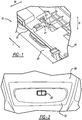
FIG. 1 illustratively depicts a perspective view of a switch assembly according to one or more embodiments of the present invention; -
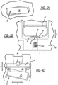
FIG. 2 illustratively depicts an external head-up view of the switch assembly referenced inFIG. 1 ; -
FIG. 3 illustratively depicts a partial exploded view of the switch assembly referenced inFIG. 1 ; -
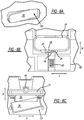
FIGs. 4A through 4C illustratively depict, respectively, an external head-up view, a top-down view, and a side view of the switch assembly referenced inFIG. 1 , at a first position; -
FIGs. 5A through 5C illustratively depict, respectively, an external head-up view, a top-down view, and a side view of the switch assembly referenced inFIG. 1 , at a second position; and -
FIGs. 6A through 6C illustratively depict, respectively, an external head-up view, a top-down view, and a side view of the switch assembly referenced inFIG. 1 , at a third position; - As referenced in the FIG.s, the same reference numerals may be used to refer to the same components. As detailed herein, different parameters and components may be used to refer to embodiments of different structures. These specific parameters and components are included as examples and are not meant to be limiting.
- According to one or more embodiments, the present invention is advantageous at least in providing a switch assembly with reduced need for space and enhanced friendliness in touch and feel. In particular, via the acknowledgement that structures sliding along a vertical or thickness direction requires relatively more operational space, the present invention in one or more embodiments works to reduce the need of operational space along the vertical or thickness direction, so as to avoid difficulties associated with limited space along the thickness direction.
- In one or more embodiments, and in view of
FIG. 1, FIG. 2 andFIG. 3 respectively show an assembled view and an exploded view of aswitch assembly 10 ofFIG. 1 . Theswitch assembly 10 includes aswitch unit 20 and aslider unit 41, where theswitch unit 20 includes abutton 26 and anarm 21 extending from thebutton 26 along a height direction H, thearm 21 including first andsecond contact portions slider unit 41 extends along a width direction W and includes anose 44 to contact the first andsecond contact portions - The length direction L is in a transverse relationship to the width direction W with an angle formed there-between of greater than zero and smaller than 180 degrees, of greater than 45 and smaller than 135 degrees, or of greater than 75 and smaller than 115 degrees. The height direction H may be viewed as coming out of the plane defined by the length direction L and the width direction W. In certain embodiments in relation to a vehicle interior, the plane defined by the length direction L and the width direction W may include or be part of a
vehicle overhead compartment 90. Accordingly the height direction H is in alignment with the thickness of thevehicle overhead compartment 90. - Referring back to
FIG. 3 , thearm 21 may further include athird contact portion 24 spaced apart from the first andsecond contact portions FIG. 3 , thefirst contact portion 22 is positioned between and spaced apart from the second andthird contact portions - Separation of the contact portions may be realized via the formation of one or more protrusions formed upon the
arm 21. With reference toFIG. 3 and further in view ofFIG. 4B ,FIG. 5B andFIG. 6B , threeseparate contact portions arm 21 viaprotrusions contact portions arm 21 via any other suitable methods such as via formation of cavities. - To provide additional design freedom, for instance to facilitate that the
arm 21 may extend along the height direction H at suitable positions, awaist 29 may be provided to be positioned between thearm 21 and thebutton 26 along the width direction H. Thewaist 29 may be of any suitable width along the width direction W, with non-limiting example value ranges thereof including 0.5 to 15 centimeters, 1.0 to 10 centimeters, or 1.5 to 7.5 centimeters. In certain embodiments, and further in view ofFIG. 3 , thewaist 29 may be positioned between thebutton 26 and any one of thecontact portions - The
arm 21 does not have to be perpendicular to thebutton 26 or thewaist 29, and may be extending along the height direction H with an angle relative to thebutton 26 or thewaist 29 to meet space limitation associated with a particular assembly. - With further reference to
FIG. 3 , and as mentioned herein elsewhere, theswitch assembly 10 further includes theslider unit 41, where theslider unit 41 includes thenose 44 which may slide back and forth along the width direction "W" and contact thecontact portions arm 21 so as to effectuate switch positioning. Thenose 44 may be of a protruding outer contour such as a sphere or hemisphere, which facilitates the sliding movement of thenose 44 to contact various contact portions or cavities positioned there-between. - The nose of the
slider unit 41 may be of any suitable shape to facilitate its engagement with any of the first, second andthird contact portions nose 44 may include or be formed of a polymeric material and in particular an elastic or resilient polymeric material so as to better engage thearm 21 for positional control. Non-limiting examples of the polymeric material include any suitable thermoplastic and thermoset polymeric materials. - In certain embodiments, and to facilitate movement of the
nose 43 along the width direction W, theslider unit 41 may further include anelastic part 43 such as a spring to support and provide elasticity to thenose 44. Via the employment of theelastic part 43, a relatively reduced force may be externally applied to effectuate movement of thenose 44 among the various contact positions, such that theslider unit 41 may contact with enhanced ease thevarious contact portions arm 21. In addition, when theslider unit 41 is at a given contact position, theelastic part 43 works to maintain thenose 44 of theslider unit 41 to be at the given contact position and not to move beyond theprotrusion 27 orprotrusion 28 without an external force applied. Theelastic part 43 is particularly useful when thenose 44 is not elastic such as when thenose 44 includes or is formed of a metallic material such as steel. - The
nose 44 may be connected to theelastic part 43 to avoid unwanted dislocation of thenose 44 away from theslider unit 41, particularly during position change in relation to any of the first, second andthird contact portions FIG. 3 , theslider unit 41 may further include aslider housing 45 to receive there-within at least partially theelastic part 43 and optionally along with thenose 44. - Referring again to
FIG. 3 , and in certain embodiments, theswitch assembly 10 may further include aswitch housing 50. Theswitch housing 50 may be of any suitable shapes dependent upon the circumstances. For instance, when positioned on the overhead panel of the vehicle, theswitch case 50 may be of any suitable configuration to match the overhead panel. Theswitch housing 50 may include anaperture 52 to receive there through at least a portion of theswitch assembly 20. Theswitch assembly 20 may be in pivoting connection with theswitch case 50 such that for instance thebutton 26 pivots about theswitch case 50 and in particular about an axis P1 P2 defined betweenconnectors - Referring back to
FIG. 3 , and further in view ofFIG. 4B ,5B and6B , asecond aperture 57 may be provided to theswitch case 50 and be positioned for instance next to and spaced apart from thefirst aperture 52. A second switch unit (not shown) similar or same to theswitch unit 20 may be provided to be at least partially received through thesecond aperture 57 and to function similarly as theswitch unit 20. This side-by-side switch and aperture configuration may be particularly useful when additional switch control is desirable. - The
switch assembly 10 may further include acontrol circuit 31 to be positioned within the housing. Thecontrol circuit 31 may be of any suitable electrical circuit types, such as printed circuit board (PCB) or circuits formed with basic circuit elements and integrated chips. Thecontrol circuit 31 may be in electrical communication with the object to be controlled, so as to impart switch control to the object. The control circuit may be in electrical communication with the overhead lights of the vehicle, so as to impart switch control to the left light or the right light. Similarly, thecontrol circuit 31 may also be employed to impart control to the front and rear headlights of the vehicle and the cabin temperature of the vehicle. Thecontrol circuit 31 is operable via the button, such that when the button is pushed down to different positions, relevant portion of the control circuit may be rendered open or close so as to impart ON or Off to the object. - To protect the
control circuit 31, acontrol circuit cover 55 may be employed to be positioned above or below thecontrol circuit 31 along the height direction H. Thecontrol circuit cover 55 may be provided withedge 49 to at least partially cover thecontrol circuit 31 such that thecontrol circuit 31 may be protected as being positioned between thecontrol circuit cover 55 and theswitch case 50. In certain embodiments, and as illustratively depicted inFIG. 3 , theslider unit 41 and in particular theslider housing 45 thereof may be positioned on thecontrol circuit cover 55, for instance, to be integral or connected thereto. Thecontrol circuit cover 55 may be relatively secured onto theswitch case 50 or any suitable locations thereof. - The
control circuit cover 55 may be integral to or be separate from the control circuit, and may be formed of any hard insulating materials such as plastics and wood. - With further reference to
FIG. 3 , and in certain embodiments, theswitch assembly 10 may further include acushion 32 to be at least partially positioned between thebutton 26 and thecontrol circuit 31. Thecushion 32 may include or be formed of an elastic material to improve on the handling friendliness thereof. Thecushion 32 may further include an electrically conducting material to connect a switch part of the control circuit, such that corresponding portions of the control circuit may be in electrical communication via the deformation of thecushion 32 upon a press of thebutton 26. It is appreciated for those in the technical field that certain switch parts of the control circuit may be positioned at the cushion such that the cushion and button may accordingly function as the control switch thereof. In certain particular embodiments, the cushion is a rubber layer with a portion thereof including an electrical conducting material. For instance, thecushion 32 includes a first portion including an elastic material and to contact thebutton 26, and thecushion 32 includes a second portion including an electricity-conducting material to contact thecontrol circuit 31, where the electricity-conducting material may include a contact part including carbon or metal and may be of a layer or a column in shape. - Accordingly the
slider unit 41 or any parts of thereof including thenose 44 and theelastic portion 43 may be positioned at any suitable locations of theswitch assembly 10, such as being positioned on and/or integral to theswitch case 50, thecushion 32, thecontrol circuit 31 and/or thecontrol circuit cover 55. In certain embodiments, and as illustratively depicted inFIG. 3 , theslider unit 41 may be formed integral to thecontrol circuit cover 55 and includes thenose 44 along with theelastic portion 43. - The
button 26 may be any one of rocker buttons, paddle buttons, knob buttons or other types of buttons. -
FIGs. 4A through 4C illustratively depict operational mechanism of theswitch assembly 10 referenced inFIG. 1 according to one or more embodiments, when being at the first operational position, where theswitch assembly 10 is at the first ormiddle contact portion 22. As depicted inFIG. 4B and FIG. 4C , thefirst contact portion 22 of thearm 21 is in contact with thenose 44 of theslider unit 41, where thebutton 26 is at the first position or an Off position. If employed, thecushion 32 is without deformation and hence without connection to thecontrol circuit 31, and therefore the control circuit is at an Off position. -
FIGs. 5A through 5C illustratively depict operational mechanism of the switch assembly referenced inFIG. 1 according to one or more embodiments, when being at the second operational position, where a left side of thebutton 26 is pressed down along for instance direction F2, such that thebutton 26 of theswitch assembly 10 is tilted toward the right, so as to be at the second position or the first ON position. As depicted inFIG. 5B and FIG. 5C , due to the press-down of the left side of thebutton 26, thearm 21 along with thebutton 26 is together tilted toward the right, such that the contact position of thenose 44 of theslider unit 41 relative to thearm 21 changes from the first contact position with contact to thefirst contact portion 22 to the second or left position with contact to thesecond contact portion 23. With the elastic force of theelastic part 43 imparted onto thenose 44 of the slider unit, thenose 44 is pressed against theleft contact portion 22 of the arm so as to keep thebutton 26 to tilt toward the right, when the external force on thebutton 26 is removed or withdrawn. With the up and down movement of the left side of thebutton 26, the left side of the cushion is accordingly compressed so as to be in contact with thecontrol circuit 31. Because the cushion includes the electrically conducting material, and upon compression, an electrical communication is established at the corresponding left side of the control circuit. - Similarly,
FIGs. 6A through 6C illustratively depict operational mechanism of the switch assembly referenced inFIG. 1 according to one or more embodiments, when being at the third operational position, where a right side of thebutton 26 is pressed down along for instance direction F3, such that thebutton 26 of theswitch assembly 10 is tilted toward the left, so as to be at the third operational position or the right position. As depicted inFIG. 6B and FIG. 6C , due to the press-down of the right side of thebutton 26, thearm 21 along with thebutton 26 is together tilted toward the left, such that the contact position of thenose 44 of theslider unit 41 relative to thearm 21 changes from the first contact position with contact to thefirst contact portion 22 to the third or right position with contact to thethird contact portion 24. With the elastic force of theelastic part 43 imparted onto thenose 44 of the slider unit, thenose 44 is pressed against the right contact portion of the arm so as to keep thebutton 26 to tilt toward the left, when the external force on thebutton 26 is removed or withdrawn. With the up and down movement of the right side of thebutton 26, the right side of the cushion is accordingly compressed so as to be in contact with thecontrol circuit 31. Because the cushion includes the electrically conducting material, and upon compression, an electrical communication is established at the corresponding left side of the control circuit. - As mentioned herein elsewhere, a pivoting movement of the
button 26 is translated to a positional change of thenose 44 relative to thearm 21 along the length direction L, and accordingly thebutton 44 and hence theswitch assembly 10 in generally may be maintained at a given position via an engagement of thenose 44 to one of the first, second andthird contact portions arm 21. Therefore although permissible, movement of theslider unit 41 and in particular thenose 44 thereof along any other directions such as the height direction H or the width direction W is not necessary. In this regard, this configuration is particularly useful when space availability is limited along the height direction H or the width direction W. - The
arm 21 may be formed via any suitable methods, including but not limited to being formed integrally, or via adhesives, via welding and rivet connections. Via an adjustment of thebutton 26, thearm 21 may be positioned at various operational positions, and accordingly the control circuit may exert controls of a number of operational functions. Thearm 21 may be formed integral to thebutton 26, and with the elastic support from theelastic part 43, a relatively small amount of force may accordingly be needed to effectuate a good switch control with relatively reduced energy loss at the switch. Because the positional change of theslider unit 41 is designed to take place along the length direction "L", and in particular along the plane defined by the longitudinal direction "L" and the width direction "W". Accordingly, unnecessary limitation imposed along the height direction "H" or the width direction "W" may be reduced, and in particular switch assembly limitation on the height direction "H" may be effectively reduced, such that the switch assembly may be employed at locations where height limitations are present. Thus, the present invention is believed to have solved technical issues in torque requirement and space consumption associated with switch assembly.
Claims (14)
- A switch assembly (10), comprising:a switch unit (20) including a button (26) and an arm (21) extending from the button along a height direction, the arm including first and second contact portions (22,23) spaced apart from each other along a longitudinal direction L; anda slider unit (41) extending along a width direction W and including a nose (44) to contact the first and second contact portions (22,23) respectively at first and second engagement positions.
- The switch assembly of claim 1, wherein the nose (44) includes a polymeric material.
- The switch assembly of claim 1 or 2, wherein the slider unit (41) further includes a spring positioned between the arm (21) and the nose (44) along the width direction W.
- The switch assembly of any of claims 1 to 3, further comprising a control circuit (31) to be positioned between the slider unit (41) and the button (26) along the height direction H.
- The switch assembly of claims 1 to 3, further comprising a control circuit (31) such that the slider unit (41) is positioned between the control circuit and the button (26).
- The switch assembly of claim 4 or 5, further comprising a cushion (32) to be positioned between the button (26) and the control circuit (31).
- The switch system of claim 4 or 5, further comprising a control circuit cover (55) to support the slider unit (41) such that the control circuit (31) is positioned between the button (26) and the control circuit cover.
- The switch assembly of any preceding claim, wherein the button (26) pivots about an axis extending along the width direction W.
- The switch assembly of any preceding claim, wherein the arm (21) further includes a third contact portion (24) spaced apart from the first and second contact portions (22,23) along the longitudinal direction L.
- The switch assembly of any preceding claim, wherein the switch unit (20) further includes a waist (29) to be positioned between the arm (21) and the button (26) along the width direction W.
- The switch assembly of any preceding claim, further comprising a switch case (50) with an aperture (52) to receive therethrough at least a portion of the switch unit (20).
- A switch assembly, comprising:a switch unit (20) including a button (26) and an arm (21) extending from the button along a height direction H, the arm including first and second contact portions (22,23) spaced apart from each other along a longitudinal direction L, the switch unit further including a waist (29) to be positioned between the arm and the button along the width direction W;a slider unit (41) extending along a width direction W and including a nose (44) to contact the first and second contact portions respectively at first and second engagement positions; anda switch base (50) with an aperture (52) to receive therethrough at least a portion of the switch unit (20).
- The switch assembly of claim 12, wherein the button (26) pivots about the switch base (50).
- The switch assembly of claim 12 or 13, wherein the arm further includes a third contact portion (24) spaced apart from the first and second contact portions (22,23) along the longitudinal direction L.
Applications Claiming Priority (1)
| Application Number | Priority Date | Filing Date | Title |
|---|---|---|---|
| CN201510751953.6A CN106683933B (en) | 2015-11-06 | 2015-11-06 | Switch assembly |
Publications (2)
| Publication Number | Publication Date |
|---|---|
| EP3166125A1 true EP3166125A1 (en) | 2017-05-10 |
| EP3166125B1 EP3166125B1 (en) | 2019-10-02 |
Family
ID=57281008
Family Applications (1)
| Application Number | Title | Priority Date | Filing Date |
|---|---|---|---|
| EP16197161.9A Active EP3166125B1 (en) | 2015-11-06 | 2016-11-03 | A switch assembly |
Country Status (3)
| Country | Link |
|---|---|
| US (1) | US10141138B2 (en) |
| EP (1) | EP3166125B1 (en) |
| CN (1) | CN106683933B (en) |
Families Citing this family (2)
| Publication number | Priority date | Publication date | Assignee | Title |
|---|---|---|---|---|
| DE102016218206A1 (en) * | 2016-09-22 | 2018-03-22 | Volkswagen Aktiengesellschaft | Unlocking unit with a variable trip switching point |
| CN111223693A (en) | 2018-11-26 | 2020-06-02 | 福特全球技术公司 | Switch assembly |
Citations (8)
| Publication number | Priority date | Publication date | Assignee | Title |
|---|---|---|---|---|
| US3053337A (en) * | 1958-04-23 | 1962-09-11 | Rau Swf Autozubehoer | Instrument housing for motor vehicles and switch construction therefor |
| GB2285885A (en) * | 1994-01-13 | 1995-07-26 | Mk Electric Ltd | An electrical switch |
| DE4415665A1 (en) * | 1994-05-04 | 1995-11-09 | Philips Patentverwaltung | Electric apparatus operating control |
| US6646211B2 (en) | 2001-08-24 | 2003-11-11 | Matsushita Electric Industrial Co., Ltd. | Switch |
| WO2012002581A1 (en) * | 2010-07-02 | 2012-01-05 | Yazaki Corporation | Switch device |
| WO2012115284A1 (en) * | 2011-02-24 | 2012-08-30 | Yazaki Corporation | Interior illumination lamp for vehicle |
| WO2012157787A1 (en) * | 2011-05-18 | 2012-11-22 | Yazaki Corporation | Contact Structure |
| WO2015012300A1 (en) * | 2013-07-26 | 2015-01-29 | 矢崎総業株式会社 | Switch structure |
Family Cites Families (15)
| Publication number | Priority date | Publication date | Assignee | Title |
|---|---|---|---|---|
| US5824977A (en) * | 1995-09-04 | 1998-10-20 | Kabushiki Kaisha T An T | Slide switch |
| US6388221B1 (en) * | 1996-05-11 | 2002-05-14 | Delphi Technologies, Inc. | Window winder switch |
| US5957273A (en) * | 1997-07-22 | 1999-09-28 | Ut Automotive Dearborn, Inc. | Universal switch |
| US5803243A (en) | 1997-07-25 | 1998-09-08 | General Motors Corporation | Latching rocker switch |
| JP2002157943A (en) * | 2000-11-17 | 2002-05-31 | Yazaki Corp | Rocking switch |
| US6590175B1 (en) | 2002-06-03 | 2003-07-08 | Defond Manufacturing Limited | Illuminated rocker switch with resistor |
| US7009127B2 (en) * | 2002-09-10 | 2006-03-07 | Siemens Ag | Switch comprising an operating rocker button |
| JP2005032491A (en) * | 2003-07-09 | 2005-02-03 | Matsushita Electric Ind Co Ltd | Switch |
| JP4301932B2 (en) * | 2003-12-22 | 2009-07-22 | 株式会社テーアンテー | Fixed contact structure of slide switch |
| US7528335B2 (en) * | 2006-09-18 | 2009-05-05 | Innotec Corporation | Light assembly for vehicle interiors |
| DE102008051228B4 (en) | 2008-10-10 | 2016-08-04 | Leopold Kostal Gmbh & Co. Kg | Rocker switch and evaluation device with a rocker switch |
| CN102208293A (en) * | 2010-03-30 | 2011-10-05 | 鸿富锦精密工业(深圳)有限公司 | Two-section push switch |
| CN203179774U (en) | 2013-05-02 | 2013-09-04 | 陈少梅 | Waterproof rocker switch with reliable electric contact |
| CN103198961B (en) | 2013-05-02 | 2014-12-10 | 陈少梅 | Waterproof rocker switch with reliable electric contact |
| CN204303642U (en) | 2014-11-12 | 2015-04-29 | 成都格瑞思文化传播有限公司 | A kind of rocker switch |
-
2015
- 2015-11-06 CN CN201510751953.6A patent/CN106683933B/en active Active
-
2016
- 2016-11-03 EP EP16197161.9A patent/EP3166125B1/en active Active
- 2016-11-07 US US15/344,767 patent/US10141138B2/en active Active
Patent Citations (8)
| Publication number | Priority date | Publication date | Assignee | Title |
|---|---|---|---|---|
| US3053337A (en) * | 1958-04-23 | 1962-09-11 | Rau Swf Autozubehoer | Instrument housing for motor vehicles and switch construction therefor |
| GB2285885A (en) * | 1994-01-13 | 1995-07-26 | Mk Electric Ltd | An electrical switch |
| DE4415665A1 (en) * | 1994-05-04 | 1995-11-09 | Philips Patentverwaltung | Electric apparatus operating control |
| US6646211B2 (en) | 2001-08-24 | 2003-11-11 | Matsushita Electric Industrial Co., Ltd. | Switch |
| WO2012002581A1 (en) * | 2010-07-02 | 2012-01-05 | Yazaki Corporation | Switch device |
| WO2012115284A1 (en) * | 2011-02-24 | 2012-08-30 | Yazaki Corporation | Interior illumination lamp for vehicle |
| WO2012157787A1 (en) * | 2011-05-18 | 2012-11-22 | Yazaki Corporation | Contact Structure |
| WO2015012300A1 (en) * | 2013-07-26 | 2015-01-29 | 矢崎総業株式会社 | Switch structure |
Also Published As
| Publication number | Publication date |
|---|---|
| EP3166125B1 (en) | 2019-10-02 |
| CN106683933A (en) | 2017-05-17 |
| CN106683933B (en) | 2020-06-30 |
| US20170133179A1 (en) | 2017-05-11 |
| US10141138B2 (en) | 2018-11-27 |
Similar Documents
| Publication | Publication Date | Title |
|---|---|---|
| EP3166125B1 (en) | A switch assembly | |
| TWI654636B (en) | Switching device | |
| US9336972B2 (en) | Switch device | |
| US9755340B2 (en) | Connector | |
| US7960664B2 (en) | Seesaw switch | |
| US7687730B2 (en) | Operating switch unit for use in automotive vehicle | |
| EP1538029A1 (en) | Floating contact assembly for a steering wheel | |
| US10559439B2 (en) | Rocker switch device | |
| CN103299387A (en) | Switch device | |
| US9524834B2 (en) | Multi-directional switch and operation input device | |
| EP3780052B1 (en) | Switch device | |
| EP3734628B1 (en) | Switch device | |
| US20130008768A1 (en) | Switch | |
| JP6729849B2 (en) | Operation unit assembly structure | |
| CN209029282U (en) | A kind of press-key structure | |
| US20230266787A1 (en) | Operation device | |
| US11536417B2 (en) | Bracket and holding structure of electrical junction box | |
| US10333240B2 (en) | Connector assembly for electrically connecting circuit boards | |
| EP2571038A1 (en) | Slide switch device | |
| EP3404684A1 (en) | An assembly comprising a switch device and a housing | |
| EP3404683A1 (en) | Assembly comprising a switch device and dome module comprising said assembly | |
| EP2983190A1 (en) | Switch | |
| CN116525343A (en) | Multi-directional operation switch device | |
| JP2013222596A (en) | Slide switch |
Legal Events
| Date | Code | Title | Description |
|---|---|---|---|
| PUAI | Public reference made under article 153(3) epc to a published international application that has entered the european phase |
Free format text: ORIGINAL CODE: 0009012 |
|
| STAA | Information on the status of an ep patent application or granted ep patent |
Free format text: STATUS: THE APPLICATION HAS BEEN PUBLISHED |
|
| AK | Designated contracting states |
Kind code of ref document: A1 Designated state(s): AL AT BE BG CH CY CZ DE DK EE ES FI FR GB GR HR HU IE IS IT LI LT LU LV MC MK MT NL NO PL PT RO RS SE SI SK SM TR |
|
| AX | Request for extension of the european patent |
Extension state: BA ME |
|
| STAA | Information on the status of an ep patent application or granted ep patent |
Free format text: STATUS: REQUEST FOR EXAMINATION WAS MADE |
|
| 17P | Request for examination filed |
Effective date: 20171027 |
|
| RBV | Designated contracting states (corrected) |
Designated state(s): AL AT BE BG CH CY CZ DE DK EE ES FI FR GB GR HR HU IE IS IT LI LT LU LV MC MK MT NL NO PL PT RO RS SE SI SK SM TR |
|
| STAA | Information on the status of an ep patent application or granted ep patent |
Free format text: STATUS: EXAMINATION IS IN PROGRESS |
|
| 17Q | First examination report despatched |
Effective date: 20190304 |
|
| GRAP | Despatch of communication of intention to grant a patent |
Free format text: ORIGINAL CODE: EPIDOSNIGR1 |
|
| STAA | Information on the status of an ep patent application or granted ep patent |
Free format text: STATUS: GRANT OF PATENT IS INTENDED |
|
| RIC1 | Information provided on ipc code assigned before grant |
Ipc: H01H 1/44 20060101ALI20190425BHEP Ipc: H01H 23/12 20060101AFI20190425BHEP Ipc: H01H 3/50 20060101ALN20190425BHEP Ipc: H01H 23/28 20060101ALI20190425BHEP |
|
| INTG | Intention to grant announced |
Effective date: 20190516 |
|
| GRAS | Grant fee paid |
Free format text: ORIGINAL CODE: EPIDOSNIGR3 |
|
| GRAA | (expected) grant |
Free format text: ORIGINAL CODE: 0009210 |
|
| STAA | Information on the status of an ep patent application or granted ep patent |
Free format text: STATUS: THE PATENT HAS BEEN GRANTED |
|
| AK | Designated contracting states |
Kind code of ref document: B1 Designated state(s): AL AT BE BG CH CY CZ DE DK EE ES FI FR GB GR HR HU IE IS IT LI LT LU LV MC MK MT NL NO PL PT RO RS SE SI SK SM TR |
|
| REG | Reference to a national code |
Ref country code: GB Ref legal event code: FG4D |
|
| REG | Reference to a national code |
Ref country code: CH Ref legal event code: EP Ref country code: AT Ref legal event code: REF Ref document number: 1187093 Country of ref document: AT Kind code of ref document: T Effective date: 20191015 |
|
| REG | Reference to a national code |
Ref country code: DE Ref legal event code: R096 Ref document number: 602016021577 Country of ref document: DE |
|
| REG | Reference to a national code |
Ref country code: IE Ref legal event code: FG4D |
|
| REG | Reference to a national code |
Ref country code: NL Ref legal event code: MP Effective date: 20191002 |
|
| REG | Reference to a national code |
Ref country code: LT Ref legal event code: MG4D |
|
| REG | Reference to a national code |
Ref country code: AT Ref legal event code: MK05 Ref document number: 1187093 Country of ref document: AT Kind code of ref document: T Effective date: 20191002 |
|
| PG25 | Lapsed in a contracting state [announced via postgrant information from national office to epo] |
Ref country code: PL Free format text: LAPSE BECAUSE OF FAILURE TO SUBMIT A TRANSLATION OF THE DESCRIPTION OR TO PAY THE FEE WITHIN THE PRESCRIBED TIME-LIMIT Effective date: 20191002 Ref country code: LT Free format text: LAPSE BECAUSE OF FAILURE TO SUBMIT A TRANSLATION OF THE DESCRIPTION OR TO PAY THE FEE WITHIN THE PRESCRIBED TIME-LIMIT Effective date: 20191002 Ref country code: BG Free format text: LAPSE BECAUSE OF FAILURE TO SUBMIT A TRANSLATION OF THE DESCRIPTION OR TO PAY THE FEE WITHIN THE PRESCRIBED TIME-LIMIT Effective date: 20200102 Ref country code: FI Free format text: LAPSE BECAUSE OF FAILURE TO SUBMIT A TRANSLATION OF THE DESCRIPTION OR TO PAY THE FEE WITHIN THE PRESCRIBED TIME-LIMIT Effective date: 20191002 Ref country code: NL Free format text: LAPSE BECAUSE OF FAILURE TO SUBMIT A TRANSLATION OF THE DESCRIPTION OR TO PAY THE FEE WITHIN THE PRESCRIBED TIME-LIMIT Effective date: 20191002 Ref country code: PT Free format text: LAPSE BECAUSE OF FAILURE TO SUBMIT A TRANSLATION OF THE DESCRIPTION OR TO PAY THE FEE WITHIN THE PRESCRIBED TIME-LIMIT Effective date: 20200203 Ref country code: AT Free format text: LAPSE BECAUSE OF FAILURE TO SUBMIT A TRANSLATION OF THE DESCRIPTION OR TO PAY THE FEE WITHIN THE PRESCRIBED TIME-LIMIT Effective date: 20191002 Ref country code: ES Free format text: LAPSE BECAUSE OF FAILURE TO SUBMIT A TRANSLATION OF THE DESCRIPTION OR TO PAY THE FEE WITHIN THE PRESCRIBED TIME-LIMIT Effective date: 20191002 Ref country code: SE Free format text: LAPSE BECAUSE OF FAILURE TO SUBMIT A TRANSLATION OF THE DESCRIPTION OR TO PAY THE FEE WITHIN THE PRESCRIBED TIME-LIMIT Effective date: 20191002 Ref country code: LV Free format text: LAPSE BECAUSE OF FAILURE TO SUBMIT A TRANSLATION OF THE DESCRIPTION OR TO PAY THE FEE WITHIN THE PRESCRIBED TIME-LIMIT Effective date: 20191002 Ref country code: NO Free format text: LAPSE BECAUSE OF FAILURE TO SUBMIT A TRANSLATION OF THE DESCRIPTION OR TO PAY THE FEE WITHIN THE PRESCRIBED TIME-LIMIT Effective date: 20200102 Ref country code: GR Free format text: LAPSE BECAUSE OF FAILURE TO SUBMIT A TRANSLATION OF THE DESCRIPTION OR TO PAY THE FEE WITHIN THE PRESCRIBED TIME-LIMIT Effective date: 20200103 |
|
| PG25 | Lapsed in a contracting state [announced via postgrant information from national office to epo] |
Ref country code: RS Free format text: LAPSE BECAUSE OF FAILURE TO SUBMIT A TRANSLATION OF THE DESCRIPTION OR TO PAY THE FEE WITHIN THE PRESCRIBED TIME-LIMIT Effective date: 20191002 Ref country code: HR Free format text: LAPSE BECAUSE OF FAILURE TO SUBMIT A TRANSLATION OF THE DESCRIPTION OR TO PAY THE FEE WITHIN THE PRESCRIBED TIME-LIMIT Effective date: 20191002 Ref country code: CZ Free format text: LAPSE BECAUSE OF FAILURE TO SUBMIT A TRANSLATION OF THE DESCRIPTION OR TO PAY THE FEE WITHIN THE PRESCRIBED TIME-LIMIT Effective date: 20191002 Ref country code: IS Free format text: LAPSE BECAUSE OF FAILURE TO SUBMIT A TRANSLATION OF THE DESCRIPTION OR TO PAY THE FEE WITHIN THE PRESCRIBED TIME-LIMIT Effective date: 20200224 |
|
| PG25 | Lapsed in a contracting state [announced via postgrant information from national office to epo] |
Ref country code: AL Free format text: LAPSE BECAUSE OF FAILURE TO SUBMIT A TRANSLATION OF THE DESCRIPTION OR TO PAY THE FEE WITHIN THE PRESCRIBED TIME-LIMIT Effective date: 20191002 |
|
| REG | Reference to a national code |
Ref country code: CH Ref legal event code: PL |
|
| REG | Reference to a national code |
Ref country code: DE Ref legal event code: R097 Ref document number: 602016021577 Country of ref document: DE |
|
| PG2D | Information on lapse in contracting state deleted |
Ref country code: IS |
|
| PG25 | Lapsed in a contracting state [announced via postgrant information from national office to epo] |
Ref country code: CH Free format text: LAPSE BECAUSE OF NON-PAYMENT OF DUE FEES Effective date: 20191130 Ref country code: LU Free format text: LAPSE BECAUSE OF NON-PAYMENT OF DUE FEES Effective date: 20191103 Ref country code: MC Free format text: LAPSE BECAUSE OF FAILURE TO SUBMIT A TRANSLATION OF THE DESCRIPTION OR TO PAY THE FEE WITHIN THE PRESCRIBED TIME-LIMIT Effective date: 20191002 Ref country code: RO Free format text: LAPSE BECAUSE OF FAILURE TO SUBMIT A TRANSLATION OF THE DESCRIPTION OR TO PAY THE FEE WITHIN THE PRESCRIBED TIME-LIMIT Effective date: 20191002 Ref country code: LI Free format text: LAPSE BECAUSE OF NON-PAYMENT OF DUE FEES Effective date: 20191130 Ref country code: EE Free format text: LAPSE BECAUSE OF FAILURE TO SUBMIT A TRANSLATION OF THE DESCRIPTION OR TO PAY THE FEE WITHIN THE PRESCRIBED TIME-LIMIT Effective date: 20191002 Ref country code: DK Free format text: LAPSE BECAUSE OF FAILURE TO SUBMIT A TRANSLATION OF THE DESCRIPTION OR TO PAY THE FEE WITHIN THE PRESCRIBED TIME-LIMIT Effective date: 20191002 Ref country code: IS Free format text: LAPSE BECAUSE OF FAILURE TO SUBMIT A TRANSLATION OF THE DESCRIPTION OR TO PAY THE FEE WITHIN THE PRESCRIBED TIME-LIMIT Effective date: 20200202 |
|
| PLBE | No opposition filed within time limit |
Free format text: ORIGINAL CODE: 0009261 |
|
| STAA | Information on the status of an ep patent application or granted ep patent |
Free format text: STATUS: NO OPPOSITION FILED WITHIN TIME LIMIT |
|
| REG | Reference to a national code |
Ref country code: BE Ref legal event code: MM Effective date: 20191130 |
|
| PG25 | Lapsed in a contracting state [announced via postgrant information from national office to epo] |
Ref country code: SM Free format text: LAPSE BECAUSE OF FAILURE TO SUBMIT A TRANSLATION OF THE DESCRIPTION OR TO PAY THE FEE WITHIN THE PRESCRIBED TIME-LIMIT Effective date: 20191002 Ref country code: SK Free format text: LAPSE BECAUSE OF FAILURE TO SUBMIT A TRANSLATION OF THE DESCRIPTION OR TO PAY THE FEE WITHIN THE PRESCRIBED TIME-LIMIT Effective date: 20191002 Ref country code: IT Free format text: LAPSE BECAUSE OF FAILURE TO SUBMIT A TRANSLATION OF THE DESCRIPTION OR TO PAY THE FEE WITHIN THE PRESCRIBED TIME-LIMIT Effective date: 20191002 |
|
| 26N | No opposition filed |
Effective date: 20200703 |
|
| PG25 | Lapsed in a contracting state [announced via postgrant information from national office to epo] |
Ref country code: IE Free format text: LAPSE BECAUSE OF NON-PAYMENT OF DUE FEES Effective date: 20191103 |
|
| PG25 | Lapsed in a contracting state [announced via postgrant information from national office to epo] |
Ref country code: SI Free format text: LAPSE BECAUSE OF FAILURE TO SUBMIT A TRANSLATION OF THE DESCRIPTION OR TO PAY THE FEE WITHIN THE PRESCRIBED TIME-LIMIT Effective date: 20191002 Ref country code: BE Free format text: LAPSE BECAUSE OF NON-PAYMENT OF DUE FEES Effective date: 20191130 |
|
| PG25 | Lapsed in a contracting state [announced via postgrant information from national office to epo] |
Ref country code: CY Free format text: LAPSE BECAUSE OF FAILURE TO SUBMIT A TRANSLATION OF THE DESCRIPTION OR TO PAY THE FEE WITHIN THE PRESCRIBED TIME-LIMIT Effective date: 20191002 |
|
| PG25 | Lapsed in a contracting state [announced via postgrant information from national office to epo] |
Ref country code: HU Free format text: LAPSE BECAUSE OF FAILURE TO SUBMIT A TRANSLATION OF THE DESCRIPTION OR TO PAY THE FEE WITHIN THE PRESCRIBED TIME-LIMIT; INVALID AB INITIO Effective date: 20161103 Ref country code: MT Free format text: LAPSE BECAUSE OF FAILURE TO SUBMIT A TRANSLATION OF THE DESCRIPTION OR TO PAY THE FEE WITHIN THE PRESCRIBED TIME-LIMIT Effective date: 20191002 |
|
| PG25 | Lapsed in a contracting state [announced via postgrant information from national office to epo] |
Ref country code: TR Free format text: LAPSE BECAUSE OF FAILURE TO SUBMIT A TRANSLATION OF THE DESCRIPTION OR TO PAY THE FEE WITHIN THE PRESCRIBED TIME-LIMIT Effective date: 20191002 |
|
| PG25 | Lapsed in a contracting state [announced via postgrant information from national office to epo] |
Ref country code: MK Free format text: LAPSE BECAUSE OF FAILURE TO SUBMIT A TRANSLATION OF THE DESCRIPTION OR TO PAY THE FEE WITHIN THE PRESCRIBED TIME-LIMIT Effective date: 20191002 |
|
| P01 | Opt-out of the competence of the unified patent court (upc) registered |
Effective date: 20230620 |
|
| PGFP | Annual fee paid to national office [announced via postgrant information from national office to epo] |
Ref country code: GB Payment date: 20231013 Year of fee payment: 8 |
|
| PGFP | Annual fee paid to national office [announced via postgrant information from national office to epo] |
Ref country code: FR Payment date: 20231010 Year of fee payment: 8 Ref country code: DE Payment date: 20231010 Year of fee payment: 8 |