EP3166013B1 - Modular exponentiation using randomized addition chains - Google Patents
Modular exponentiation using randomized addition chains Download PDFInfo
- Publication number
- EP3166013B1 EP3166013B1 EP16195485.4A EP16195485A EP3166013B1 EP 3166013 B1 EP3166013 B1 EP 3166013B1 EP 16195485 A EP16195485 A EP 16195485A EP 3166013 B1 EP3166013 B1 EP 3166013B1
- Authority
- EP
- European Patent Office
- Prior art keywords
- addition chain
- modular exponentiation
- elements
- randomized
- code
- Prior art date
- Legal status (The legal status is an assumption and is not a legal conclusion. Google has not performed a legal analysis and makes no representation as to the accuracy of the status listed.)
- Active
Links
- 238000000034 method Methods 0.000 claims description 54
- 230000015654 memory Effects 0.000 claims description 34
- 238000004891 communication Methods 0.000 claims description 9
- 238000007792 addition Methods 0.000 description 45
- 230000006870 function Effects 0.000 description 8
- 230000008569 process Effects 0.000 description 4
- 238000010586 diagram Methods 0.000 description 3
- 230000003287 optical effect Effects 0.000 description 3
- 238000013478 data encryption standard Methods 0.000 description 2
- 238000012986 modification Methods 0.000 description 2
- 230000004048 modification Effects 0.000 description 2
- 230000008520 organization Effects 0.000 description 2
- 230000003068 static effect Effects 0.000 description 2
- 238000013459 approach Methods 0.000 description 1
- 230000003247 decreasing effect Effects 0.000 description 1
- 230000001419 dependent effect Effects 0.000 description 1
- 238000013461 design Methods 0.000 description 1
- 230000000694 effects Effects 0.000 description 1
- 230000007246 mechanism Effects 0.000 description 1
- 238000010295 mobile communication Methods 0.000 description 1
- 238000009877 rendering Methods 0.000 description 1
- 230000007704 transition Effects 0.000 description 1
- 238000012795 verification Methods 0.000 description 1
Images

Classifications
-
- H—ELECTRICITY
- H04—ELECTRIC COMMUNICATION TECHNIQUE
- H04L—TRANSMISSION OF DIGITAL INFORMATION, e.g. TELEGRAPHIC COMMUNICATION
- H04L9/00—Cryptographic mechanisms or cryptographic arrangements for secret or secure communications; Network security protocols
- H04L9/30—Public key, i.e. encryption algorithm being computationally infeasible to invert or user's encryption keys not requiring secrecy
- H04L9/3066—Public key, i.e. encryption algorithm being computationally infeasible to invert or user's encryption keys not requiring secrecy involving algebraic varieties, e.g. elliptic or hyper-elliptic curves
-
- H—ELECTRICITY
- H04—ELECTRIC COMMUNICATION TECHNIQUE
- H04L—TRANSMISSION OF DIGITAL INFORMATION, e.g. TELEGRAPHIC COMMUNICATION
- H04L9/00—Cryptographic mechanisms or cryptographic arrangements for secret or secure communications; Network security protocols
- H04L9/08—Key distribution or management, e.g. generation, sharing or updating, of cryptographic keys or passwords
- H04L9/0861—Generation of secret information including derivation or calculation of cryptographic keys or passwords
- H04L9/0869—Generation of secret information including derivation or calculation of cryptographic keys or passwords involving random numbers or seeds
-
- G—PHYSICS
- G06—COMPUTING; CALCULATING OR COUNTING
- G06F—ELECTRIC DIGITAL DATA PROCESSING
- G06F7/00—Methods or arrangements for processing data by operating upon the order or content of the data handled
- G06F7/60—Methods or arrangements for performing computations using a digital non-denominational number representation, i.e. number representation without radix; Computing devices using combinations of denominational and non-denominational quantity representations, e.g. using difunction pulse trains, STEELE computers, phase computers
- G06F7/72—Methods or arrangements for performing computations using a digital non-denominational number representation, i.e. number representation without radix; Computing devices using combinations of denominational and non-denominational quantity representations, e.g. using difunction pulse trains, STEELE computers, phase computers using residue arithmetic
- G06F7/723—Modular exponentiation
-
- G—PHYSICS
- G06—COMPUTING; CALCULATING OR COUNTING
- G06F—ELECTRIC DIGITAL DATA PROCESSING
- G06F2207/00—Indexing scheme relating to methods or arrangements for processing data by operating upon the order or content of the data handled
- G06F2207/72—Indexing scheme relating to groups G06F7/72 - G06F7/729
- G06F2207/7276—Additional details of aspects covered by group G06F7/723
- G06F2207/7295—Additional details of aspects covered by group G06F7/723 using an addition chain, or an addition-subtraction chain
-
- H—ELECTRICITY
- H04—ELECTRIC COMMUNICATION TECHNIQUE
- H04L—TRANSMISSION OF DIGITAL INFORMATION, e.g. TELEGRAPHIC COMMUNICATION
- H04L2209/00—Additional information or applications relating to cryptographic mechanisms or cryptographic arrangements for secret or secure communication H04L9/00
- H04L2209/34—Encoding or coding, e.g. Huffman coding or error correction
Definitions
- Various embodiments disclosed herein relate generally to cryptographic functions.
- White-box cryptography is concerned with the design and analysis of software implementations of cryptographic algorithms engineered to execute on untrusted platforms. Particularly, this is the scenario where the user of a particular device can decrypt messages (with a secret key) which are encrypted with his public key but is unable to extract or derive sufficient information to recover this secret key. Furthermore, it is assumed that the user can be the attacker: for example, an attacker may have full access to the software implementation, can pause, alter and resume the execution of the software implementation at any time.
- the white-box model was first studied in the context of symmetric cryptographic algorithms such as Advanced Encryption Standard (AES) or Data Encryption Standard (DES).
- AES Advanced Encryption Standard
- DES Data Encryption Standard
- a device for generating code which implements modular exponentiation including: a memory used to store a lookup table; and a processor in communication with the memory, the processor configured to: receive information for a generated randomized addition chain; output code for implementing the modular exponentiation based upon the generated randomized chain, which loads elements from the lookup table including intermediate results which utilize the information for a generated randomized addition chain; and output code for implementing the modular exponentiation which uses the loaded elements to compute the next element.
- Various embodiments described herein relate to a method for generating code which implements modular exponentiation, the method including: receiving information for a generated randomized addition chain; outputting code for implementing the modular exponentiation based upon the generated randomized chain, which loads elements from the lookup table including intermediate results which utilize the information for a generated randomized addition chain; and outputting code for implementing the modular exponentiation which uses the loaded elements to compute the next element.
- Embodiments described allow one to compute a modular exponentiation where the exponent is not directly revealed. This may be an important property when computing asymmetric cryptographic primitives in the white-box attack model.
- Embodiments include a tool which on input of the secret exponent d, generates source code which implements a randomized addition chain to compute the modular exponentiation c d mod N. Techniques on how to construct such random chains efficiently and how to automatically generate them are included.
- the exponent d itself is not embedded directly in this source code. Even when using the same exponent multiple times, new implementations will be generated (with possibly different countermeasures to protect the code itself).
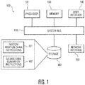
- FIG. 1 illustrates an example of a hardware system 100 for implementing the asymmetric cryptographic schemes or the lookup table generation schemes described herein.
- the hardware system 100 may correspond to virtually any device that may participate in a digital signature scheme such as, for example, a personal computer, laptop, tablet, mobile communications device, server, blade, smart card, near field communication (NFC) device, or other device.
- the hardware system may correspond to a set-top box for receiving and rendering digital content or a server for providing digital content.
- DRM digital rights management
- banking applications and generally protecting cryptographic keys in devices such as mobile phones and television set-top boxes.
- the device 100 includes a processor 120, memory 130, user interface 140, network interface 150, and storage 160 interconnected via one or more system buses 110. It will be understood that FIG. 1 constitutes, in some respects, an abstraction and that the actual organization of the components of the device 100 may be more complex than illustrated.
- the processor 120 may be any hardware device capable of executing instructions stored in the memory 130 or the storage 150.
- the processor may include a microprocessor, field programmable gate array (FPGA), application-specific integrated circuit (ASIC), or other similar devices.
- FPGA field programmable gate array
- ASIC application-specific integrated circuit
- the memory 130 may include various memories such as, for example L1, L2, or L3 cache or system memory. As such, the memory 130 may include static random access memory (SRAM), dynamic RAM (DRAM), flash memory, read only memory (ROM), or other similar memory devices.
- SRAM static random access memory
- DRAM dynamic RAM
- ROM read only memory
- the user interface 140 may include one or more devices for enabling communication with a user such as an administrator.
- the user interface 140 may include a display, a mouse, and a keyboard for receiving user commands.
- the user interface 140 may include a command line interface or graphical user interface that may be presented to a remote terminal via the network interface 150.
- the network interface 150 may include one or more devices for enabling communication with other hardware devices.
- the network interface 150 may include a network interface card (NIC) configured to communicate according to the Ethernet protocol.
- NIC network interface card
- the network interface 150 may implement a TCP/IP stack for communication according to the TCP/IP protocols.
- TCP/IP protocols Various alternative or additional hardware or configurations for the network interface 150 will be apparent.
- the storage 160 may include one or more machine-readable storage media such as read-only memory (ROM), random-access memory (RAM), magnetic disk storage media, optical storage media, flash-memory devices, or similar storage media.
- ROM read-only memory
- RAM random-access memory
- magnetic disk storage media magnetic disk storage media
- optical storage media flash-memory devices
- flash-memory devices or similar storage media.
- the storage 160 may store instructions for execution by the processor 120 or data upon with the processor 120 may operate.
- the storage 160 may include random addition chain instructions 161.
- hardware device 100 may implement source code generation instructions 162.
- the memory 130 may also be considered to constitute a “storage device” and the storage 160 may be considered a “memory.” Various other arrangements will be apparent. Further, the memory 130 and storage 160 may both be considered to be “non-transitory machine-readable media.” As used herein, the term “non-transitory” will be understood to exclude transitory signals but to include all forms of storage, including both volatile and non-volatile memories.
- the various components may be duplicated in various embodiments.
- the processor 120 may include multiple microprocessors that are configured to independently execute the methods described herein or are configured to perform steps or subroutines of the methods described herein such that the multiple processors cooperate to achieve the functionality described herein.
- the various components may be physically located in diverse machines.
- the processor 120 may include a first microprocessor in a first data center server and a second microprocessor in a second data center server.
- a first microprocessor in a first data center server and a second microprocessor in a second data center server.
- FIG. 2 illustrates an example of a system for providing a user device secure content and a software application that processes the secure content.
- the system includes a content server 200, application server 220, user devices 250, 252, and a data network 240.
- the user devices 250, 252 may request access to secure content provided by the content server 200 via data network 240.
- the data network can be any data network providing connectivity between the user devices 250, 252 and the content server 200 and application server 220.
- the user devices 250, 252 may be one of a plurality of devices, for example, set top boxes, media streamers, digital video recorders, tablets, mobile phones, laptop computers, portable media devices, smart watches, desktop computers, media servers, etc.
- the user request for access may first require the downloading of a software application that may be used to process the secure content provided by the content server 200.
- the software application may be downloaded from the application server 220.
- the software application may be obscured using the techniques described above as well as operate as described above.
- the user devices 250, 252 install the software application, the user device may then download secure content from the content server 200 and access the secure content using the downloaded software application.
- the downloaded software application may perform decryption of encrypted content received from the content server.
- the software application may perform other secure operations, such as for example, encryption, digital signature generation and verification, etc.
- the content server 200 may control the access to the secure content provided to the user devices 250, 252. As a result when the content server 200 receives a request for secure content, the content server 200 may transmit the secure content to the requesting user device. Likewise, the application server 220 may control access to the software application provided to the user devices 250, 252. As a result when the content server 220 receives a request for the software application, the application server 220 may transmit the software application to the requesting user device.
- a user device requesting the software application or secure content may also be authenticated by the respective servers, before providing the software application or secure content to the user device.
- the content server 200 may include a processor 202, memory 204, user interface 206, network interface 210, and content storage 212 interconnected via one or more system buses 208. It will be understood that FIG. 2 constitutes, in some respects, an abstraction and that the actual organization of the components of the device 200 may be more complex than illustrated.
- the processor 202 may be any hardware device capable of executing instructions stored in memory 204 or storage 212.
- the processor may include a microprocessor, field programmable gate array (FPGA), application-specific integrated circuit (ASIC), or other similar devices.
- FPGA field programmable gate array
- ASIC application-specific integrated circuit
- the memory 204 may include various memories such as, for example L1, L2, or L3 cache or system memory. As such, the memory 204 may include static random access memory (SRAM), dynamic RAM (DRAM), flash memory, read only memory (ROM), or other similar memory devices.
- SRAM static random access memory
- DRAM dynamic RAM
- ROM read only memory
- the user interface 206 may include one or more devices for enabling communication with a user such as an administrator.
- the user interface 206 may include a display, a mouse, and a keyboard for receiving user commands.
- the network interface 210 may include one or more devices for enabling communication with other hardware devices.
- the network interface 210 may include a network interface card (NIC) configured to communicate according to the Ethernet protocol.
- the network interface 210 may implement a TCP/IP stack for communication according to the TCP/IP protocols.
- NIC network interface card
- TCP/IP protocols Various alternative or additional hardware or configurations for the network interface 210 will be apparent.
- the content storage 212 may include one or more machine-readable content storage media such as read-only memory (ROM), random-access memory (RAM), magnetic disk storage media, optical storage media, flash-memory devices, or similar storage media.
- ROM read-only memory
- RAM random-access memory
- magnetic disk storage media such as magnetic tape, magnetic disks, magnetic disks, optical disks, flash-memory devices, or similar storage media.
- the content storage 212 may store content to be provided to users.
- the application server 220 includes elements like those in the content server 200 and the description of the like elements in the content server 200 apply to the application server 220. Also, the content storage 212 is replaced by application storage 232. Further, it is noted that the content server and applications server may be implemented on a single server. Also, such servers may be implemented on distributed computer systems as well as on cloud computer systems.
- the modular exponentiation, encryption, or digital signature methods described herein may be deployed and utilized within the system of FIG. 2 or similar systems in various manners.
- the user devices 250, 252 may be provided by a manufacturer or other seller preconfigured to transmit signed messages to the content server 200 to request the provision of content.
- the user devices 250, 252 may not be fully preconfigured for such operation; instead, the application server 220 may communicate with the user devices 250, 252 to effect such configuration.
- the application server may transmit code instructions for implementing the methods described herein or data defining one or more lookup tables.
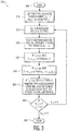
- FIG. 3 illustrates an example of a method for generating a random addition chain 300.
- the exponent d and the integer parameters (p 1 , b 1 , b 2 ), such that p 1 ⁇ b 1 and b 2 is larger than the expected length of the addition chain, may be used to construct the random addition chain using the following steps.
- the method for generating a random addition chain 300 may begin in step 305.
- Method for generating a random addition chain 300 may proceed to step 310.
- Method for generating a random addition chain 300 may proceed to step 315.
- the method may set the boolean value m to zero to mark that there is no overflow in step 315.
- Method for generating a random addition chain 300 may proceed to step 320 where the method may pick a uniform random positive integer r 1 from the range [0, b 1 - 1].
- the method for generating a random addition chain 300 may proceed to step 340.
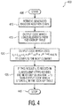
- FIG. 4 illustrates an example of a method for generating source code 400.
- the random star addition chain When the random star addition chain has been generated one can output the source code which computes the desired modular multiplication c d mod N.
- the method for generating source code 400 may begin in step 405 and proceed to step 410.
- the method for generating source code 400 may then proceed to step 415.
- the method for generating source code 400 may then proceed to step 420.
- the method may output code which uses these elements to compute the next element: C i ⁇ C i ⁇ 1 ⁇ C j ⁇ C a i ⁇ 1 ⁇ C a j ⁇ C a i ⁇ 1 + a j mod N .
- Method for generating source code 400 may then proceed to step 425.
- step 425 when this result c i is needed in subsequent steps besides the next step (iteration i + 1) then the method may output code which stores c i in the look-up table.
- the loading of the elements from the look-up table in step 420 may be computed differently.
- the two indices i - 1 and j one may use two functions f i 1 and f i 2 specific to iteration i, which use two hard-coded values ⁇ i and ⁇ i .
- the functionality of function f i 1 and f i 2 should be such that it is harder to distinguish what it is exactly computing and what is other (functional) code.
- the location where to store the result (if needed) in step 425 can be the result from (another) function f i 3 ( ⁇ i ).
- Embodiments may allow one to instantiate white-box asymmetric cryptography based on modular exponentiation.
- DRM digital right management
- banking applications as well as protecting cryptographic keys in mobile phones, television set top boxes etcetera.
- the tool which generates this source code consists of two parts.
- the first part which constructs a random addition chain for the exponent d and the second part which, given this addition chain, generates the source code (with potentially countermeasures against attackers) built-in.
- the third party who is allowed to know the secret exponent d, generates source code which implements exponentiation modulo N using a random addition chain.
- the parameters of this generator may be adjusted and present a trade-off between speed, code size and the number of random implementations which can be generated.
- various embodiments of the invention may be implemented in hardware.
- various embodiments may be implemented as instructions stored on a non-transitory machine-readable storage medium, such as a volatile or non-volatile memory, which may be read and executed by at least one processor to perform the operations described in detail herein.
- a machine-readable storage medium may include any mechanism for storing information in a form readable by a machine, such as a personal or laptop computer, a server, or other computing device.
- a non-transitory machine-readable storage medium excludes transitory signals but may include both volatile and non-volatile memories, including but not limited to read-only memory (ROM), random-access memory (RAM), magnetic disk storage media, optical storage media, flash-memory devices, and similar storage media.
- any block diagrams herein represent conceptual views of illustrative circuitry embodying the principles of the invention.
- any flow charts, flow diagrams, state transition diagrams, pseudo code, and the like represent various processes which may be substantially represented in machine readable media and so executed by a computer or processor, whether or not such computer or processor is explicitly shown.
Description
- Various embodiments disclosed herein relate generally to cryptographic functions.
- White-box cryptography is concerned with the design and analysis of software implementations of cryptographic algorithms engineered to execute on untrusted platforms. Particularly, this is the scenario where the user of a particular device can decrypt messages (with a secret key) which are encrypted with his public key but is unable to extract or derive sufficient information to recover this secret key. Furthermore, it is assumed that the user can be the attacker: for example, an attacker may have full access to the software implementation, can pause, alter and resume the execution of the software implementation at any time. The white-box model was first studied in the context of symmetric cryptographic algorithms such as Advanced Encryption Standard (AES) or Data Encryption Standard (DES).
- Various asymmetric cryptographic schemes include modular exponentiation as the main computational operation. Modular exponentiation computes, for example,


- The product is over the distinct prime numbers p > 1 dividing N. There are two special cases used in cryptography including:
- 1. When N is prime then φ (N) = N - 1.
- 2. When N = p·q, for two primes p and q such that 1 < p ≠ q > 1, then φ (N) = (p - 1)(q - 1).
- A brief summary of various embodiments is presented below. Some simplifications and omissions may be made in the following summary, which is intended to highlight and introduce some aspects of the various embodiments, but not to limit the scope of the invention. Detailed descriptions of a preferred embodiment adequate to allow those of ordinary skill in the art to make and use the inventive concepts will follow in later sections.
- Various embodiments described herein relate to a device for generating code which implements modular exponentiation, the device including: a memory used to store a lookup table; and a processor in communication with the memory, the processor configured to: receive information for a generated randomized addition chain; output code for implementing the modular exponentiation based upon the generated randomized chain, which loads elements from the lookup table including intermediate results which utilize the information for a generated randomized addition chain; and output code for implementing the modular exponentiation which uses the loaded elements to compute the next element.
- Various embodiments described herein relate to a method for generating code which implements modular exponentiation, the method including: receiving information for a generated randomized addition chain; outputting code for implementing the modular exponentiation based upon the generated randomized chain, which loads elements from the lookup table including intermediate results which utilize the information for a generated randomized addition chain; and outputting code for implementing the modular exponentiation which uses the loaded elements to compute the next element.
- Further embodiments are defined in the dependent claims. It is noted that the embodiments have been described with reference to different subject-matters. In particular, some embodiments may have been described with reference to method-type claims whereas other embodiments may have been described with reference to apparatus-type claims. However, a person skilled in the art will gather from the above that, unless otherwise indicated, in addition to any combination of features belonging to one type of subject-matter also any combination of features relating to different subject-matters, in particular a combination of features of the method-type claims and features of the apparatus-type claims, is considered to be disclosed with this document.
- In order to better understand various embodiments, reference is made to the accompanying drawings, wherein:
-
FIG. 1 illustrates an example of ahardware system 100 for implementing the asymmetric cryptographic schemes or the lookup table generation schemes; -
FIG. 2 illustrates an example of a system for providing a user device secure content and a software application that processes the secure content; -
FIG. 3 illustrates an example of a method for generating a random addition chain; and -
FIG. 4 illustrates an example of a method for generating source code. - To facilitate understanding, identical reference numerals have been used to designate elements having substantially the same or similar structure or substantially the same or similar function.
- The description and drawings presented herein illustrate various principles. It will be appreciated that those skilled in the art will be able to devise various arrangements that, although not explicitly described or shown herein, embody these principles and are included within the scope of this disclosure. As used herein, the term, "or" refers to a non-exclusive or (i.e., and/or), unless otherwise indicated (e.g., "or else" or "or in the alternative"). Additionally, the various embodiments described herein are not necessarily mutually exclusive and may be combined to produce additional embodiments that incorporate the principles described herein.
- One method of computing modular exponentiation is based on addition chains. A finite sequence of positive integers a0 = 1, a1,..., ar = s, is called an addition chain of length r which computes s if every element ai can be written as a sum aj + ak of preceding elements.
- One method to compute modular exponentiation using addition chains includes the square- and-multiply algorithm. This approach is also known as the double-and-add algorithm (when the group is written additively). The idea is based on the fact that

- Consider an example exponent d = 9997. In binary this number is 999710 = 100111000011012. The following addition chain based on this binary representation


- computes d (where D stands for double and A for addition). When one translates this example to the modular exponentiation setting this is just what the multiply-and-add algorithm would compute. Given an input base b, the modular exponentiation c = bd mod N can be computed by replacing the doublings by squarings and the additions by multiplication


- Embodiments described allow one to compute a modular exponentiation where the exponent is not directly revealed. This may be an important property when computing asymmetric cryptographic primitives in the white-box attack model.
- Embodiments include a tool which on input of the secret exponent d, generates source code which implements a randomized addition chain to compute the modular exponentiation cd mod N. Techniques on how to construct such random chains efficiently and how to automatically generate them are included. The exponent d itself is not embedded directly in this source code. Even when using the same exponent multiple times, new implementations will be generated (with possibly different countermeasures to protect the code itself). These implementations provide a first step in making software implementations secure in the white-box attack model which need to compute modular exponentiations.
-
FIG. 1 illustrates an example of ahardware system 100 for implementing the asymmetric cryptographic schemes or the lookup table generation schemes described herein. Thehardware system 100 may correspond to virtually any device that may participate in a digital signature scheme such as, for example, a personal computer, laptop, tablet, mobile communications device, server, blade, smart card, near field communication (NFC) device, or other device. For example, the hardware system may correspond to a set-top box for receiving and rendering digital content or a server for providing digital content. Various applications of the method described herein will be apparent such as, for example, digital rights management (DRM), banking applications, and generally protecting cryptographic keys in devices such as mobile phones and television set-top boxes. - As shown, the
device 100 includes aprocessor 120,memory 130,user interface 140,network interface 150, andstorage 160 interconnected via one ormore system buses 110. It will be understood thatFIG. 1 constitutes, in some respects, an abstraction and that the actual organization of the components of thedevice 100 may be more complex than illustrated. - The
processor 120 may be any hardware device capable of executing instructions stored in thememory 130 or thestorage 150. As such, the processor may include a microprocessor, field programmable gate array (FPGA), application-specific integrated circuit (ASIC), or other similar devices. - The
memory 130 may include various memories such as, for example L1, L2, or L3 cache or system memory. As such, thememory 130 may include static random access memory (SRAM), dynamic RAM (DRAM), flash memory, read only memory (ROM), or other similar memory devices. - The
user interface 140 may include one or more devices for enabling communication with a user such as an administrator. For example, theuser interface 140 may include a display, a mouse, and a keyboard for receiving user commands. In some embodiments, theuser interface 140 may include a command line interface or graphical user interface that may be presented to a remote terminal via thenetwork interface 150. - The
network interface 150 may include one or more devices for enabling communication with other hardware devices. For example, thenetwork interface 150 may include a network interface card (NIC) configured to communicate according to the Ethernet protocol. Additionally, thenetwork interface 150 may implement a TCP/IP stack for communication according to the TCP/IP protocols. Various alternative or additional hardware or configurations for thenetwork interface 150 will be apparent. - The
storage 160 may include one or more machine-readable storage media such as read-only memory (ROM), random-access memory (RAM), magnetic disk storage media, optical storage media, flash-memory devices, or similar storage media. In various embodiments, thestorage 160 may store instructions for execution by theprocessor 120 or data upon with theprocessor 120 may operate. - For example, where the
hardware device 100 implements a device using white-box asymmetric cryptography based on modular exponentiation, thestorage 160 may include randomaddition chain instructions 161. Similarlyhardware device 100 may implement sourcecode generation instructions 162. - It will be apparent that various information described as stored in the
storage 160 may be additionally or alternatively stored in thememory 130. In this respect, thememory 130 may also be considered to constitute a "storage device" and thestorage 160 may be considered a "memory." Various other arrangements will be apparent. Further, thememory 130 andstorage 160 may both be considered to be "non-transitory machine-readable media." As used herein, the term "non-transitory" will be understood to exclude transitory signals but to include all forms of storage, including both volatile and non-volatile memories. - While the
hardware device 100 is shown as including one of each described component, the various components may be duplicated in various embodiments. For example, theprocessor 120 may include multiple microprocessors that are configured to independently execute the methods described herein or are configured to perform steps or subroutines of the methods described herein such that the multiple processors cooperate to achieve the functionality described herein. In other embodiments, such as those embodiments wherein thedevice 100 is implemented in a cloud computing environment, the various components may be physically located in diverse machines. For example, theprocessor 120 may include a first microprocessor in a first data center server and a second microprocessor in a second data center server. Various additional arrangements will be apparent. -
FIG. 2 illustrates an example of a system for providing a user device secure content and a software application that processes the secure content. The system includes acontent server 200,application server 220,user devices data network 240. Theuser devices content server 200 viadata network 240. The data network can be any data network providing connectivity between theuser devices content server 200 andapplication server 220. Theuser devices - The user request for access may first require the downloading of a software application that may be used to process the secure content provided by the
content server 200. The software application may be downloaded from theapplication server 220. The software application may be obscured using the techniques described above as well as operate as described above. Once theuser devices content server 200 and access the secure content using the downloaded software application. For example, the downloaded software application may perform decryption of encrypted content received from the content server. In other embodiments, the software application may perform other secure operations, such as for example, encryption, digital signature generation and verification, etc. - The
content server 200 may control the access to the secure content provided to theuser devices content server 200 receives a request for secure content, thecontent server 200 may transmit the secure content to the requesting user device. Likewise, theapplication server 220 may control access to the software application provided to theuser devices content server 220 receives a request for the software application, theapplication server 220 may transmit the software application to the requesting user device. A user device requesting the software application or secure content may also be authenticated by the respective servers, before providing the software application or secure content to the user device. - The
content server 200 may include aprocessor 202,memory 204,user interface 206,network interface 210, andcontent storage 212 interconnected via one ormore system buses 208. It will be understood thatFIG. 2 constitutes, in some respects, an abstraction and that the actual organization of the components of thedevice 200 may be more complex than illustrated. - The
processor 202 may be any hardware device capable of executing instructions stored inmemory 204 orstorage 212. As such, the processor may include a microprocessor, field programmable gate array (FPGA), application-specific integrated circuit (ASIC), or other similar devices. - The
memory 204 may include various memories such as, for example L1, L2, or L3 cache or system memory. As such, thememory 204 may include static random access memory (SRAM), dynamic RAM (DRAM), flash memory, read only memory (ROM), or other similar memory devices. - The
user interface 206 may include one or more devices for enabling communication with a user such as an administrator. For example, theuser interface 206 may include a display, a mouse, and a keyboard for receiving user commands. - The
network interface 210 may include one or more devices for enabling communication with other hardware devices. For example, thenetwork interface 210 may include a network interface card (NIC) configured to communicate according to the Ethernet protocol. Additionally, thenetwork interface 210 may implement a TCP/IP stack for communication according to the TCP/IP protocols. Various alternative or additional hardware or configurations for thenetwork interface 210 will be apparent. - The
content storage 212 may include one or more machine-readable content storage media such as read-only memory (ROM), random-access memory (RAM), magnetic disk storage media, optical storage media, flash-memory devices, or similar storage media. In various embodiments, thecontent storage 212 may store content to be provided to users. - The
application server 220 includes elements like those in thecontent server 200 and the description of the like elements in thecontent server 200 apply to theapplication server 220. Also, thecontent storage 212 is replaced byapplication storage 232. Further, it is noted that the content server and applications server may be implemented on a single server. Also, such servers may be implemented on distributed computer systems as well as on cloud computer systems. - As will be understood, the modular exponentiation, encryption, or digital signature methods described herein may be deployed and utilized within the system of
FIG. 2 or similar systems in various manners. For example, theuser devices content server 200 to request the provision of content. Alternatively, theuser devices application server 220 may communicate with theuser devices -
FIG. 3 illustrates an example of a method for generating arandom addition chain 300. - One embodiment may include a subset of all addition chains, the so-called star addition chain, but the presented techniques may apply in more generality to all addition chains. A Brauer chain or star addition chain is an addition chain in which one of the summands is always the previous element of the chain:

- The exponent d and the integer parameters (p1, b1, b2), such that p1 ≤ b1 and b2 is larger than the expected length of the addition chain, may be used to construct the random addition chain using the following steps. The method for generating a
random addition chain 300 may begin instep 305. - Method for generating a
random addition chain 300 may proceed to step 310. The method may initially set the first addition chain element a0 = 1 and the counter i = 1 instep 310. - Method for generating a
random addition chain 300 may proceed to step 315. The method may set the boolean value m to zero to mark that there is no overflow instep 315. - Method for generating a
random addition chain 300 may proceed to step 320 where the method may pick a uniform random positive integer r1 from the range [0, b1 - 1]. - Method for generating a
random addition chain 300 may proceed to step 325 where the method may assign m = 1, If r1 ≤ p1 and 2 · ai-1 > d. - Method for generating a
random addition chain 300 may proceed to step 330 where the method may assign ai = ai-1 + ai-1 if r1 ≤ p1 and 2 · ai-1 ≤ d. - The method for generating a
random addition chain 300 may proceed to step 335. If r1 > p1 or m = 1, then a random previous element from the addition chain is added such that the result is smaller than d. This may be done as follows, first one may pick a uniform random positive integer r2 from the range [0, b2-1]. Check if ai-1 +aj ≤ d where the index j = r2 mod i. If so, one may set ai = ai-1 + aj and continue. If not, and hence ai-1 + aj > d, one may pick another previous element from the addition chain. This may be done by picking another random element or decreasing the index j by one until one may have found an addition chain element aj such that ai = ai-1 + aj ≤ d. - The method for generating a
random addition chain 300 may proceed to step 340. The method may increase the length of the addition chain by one (i = i + 1) and the method may proceed back to step 310 when ai-1 ≠ d. Otherwise, the method may proceed to step 345 where it may stop. - A star addition chain has been obtained, as a0 = 1, a1,..., ai-2, ai-1 = d of length r = i-1 which computes the exponent d. This chain may be computed using i-1 additions, and the required storage depends on the selection of the parameters (p1, b1, b2) and the uniform random values used in the steps described above. For instance, computing doubling steps ai = ai-1 + ai-1 do not require additional storage while when a previous element aj with j < i - 1 is to be used in the addition this value needs to be stored for re-usage later.
-
FIG. 4 illustrates an example of a method for generatingsource code 400. - When the random star addition chain has been generated one can output the source code which computes the desired modular multiplication cd mod N. The implementation to be generated may assume it receives some value c as input (whereas the value d is fixed and secret and the modulus N is fixed and public). This means that the code generator outputs code which sets the first value in the modular exponentiation c0 to the input value raised to the first element in the addition chain (a0 = 1): c0 = c = ca0 mod N . The implementation uses temporary memory, which may be a look-up table, to store the intermediate results which are re-used when computing the modular exponentiation. The size of the look-up table depends on the properties of the generated random star addition chain. For each step in the addition chain one may do the following (starting at i = 1 until we reach the final element r)
- The method for generating
source code 400 may begin instep 405 and proceed to step 410. Instep 420 the method may retrieve the information from the method for generating arandom addition chain 300, which allows one to deduce that ai = ai-1 + aj, where 0 ≤ j < i. - The method for generating
source code 400 may then proceed to step 415. Instep 420 the method may output code which loads the elements Ci-1 = C ai-1 mod N and Ci = Caj mod N from the look-up table kept by the implementation. - The method for generating
source code 400 may then proceed to step 420. Instep 420 the method may output code which uses these elements to compute the next element:
- Method for generating
source code 400 may then proceed to step 425. Instep 425, when this result ci is needed in subsequent steps besides the next step (iteration i + 1) then the method may output code which stores ci in the look-up table. - In practice,
step 420 does not need to be explicitly load the element ci-1 = cai-1 mod N since it was computed in the previous step and therefore is most likely still in local registers / variables. - Various countermeasures to attackers may be added. For instance, in order to make it more difficult for a white-box attacker to follow exactly what the implementation is doing, the loading of the elements from the look-up table in
step 420 may be computed differently. Instead of hard-coding the two indices i - 1 and j one may use two functions fi 1 and fi 2 specific to iteration i, which use two hard-coded values αi and βi. The functionality of function fi 1 and fi 2 should be such that it is harder to distinguish what it is exactly computing and what is other (functional) code. These functions may be chosen such that fi 1(αi) = i - 1 and fi 2(βi) = j (and return pseudo-random values for all other inputs), in the case that the second operand is not needed (i.e. when computing the modular squaring) this could, for instance, be indicated by a negative outcome of fi 2. Similarly, the location where to store the result (if needed) instep 425 can be the result from (another) function fi 3(γi). - Embodiments may allow one to instantiate white-box asymmetric cryptography based on modular exponentiation. There includes widespread application ranging from digital right management (DRM), through banking applications, as well as protecting cryptographic keys in mobile phones, television set top boxes etcetera.
- The tool which generates this source code consists of two parts. The first part, which constructs a random addition chain for the exponent d and the second part which, given this addition chain, generates the source code (with potentially countermeasures against attackers) built-in. The third party, who is allowed to know the secret exponent d, generates source code which implements exponentiation modulo N using a random addition chain. The parameters of this generator may be adjusted and present a trade-off between speed, code size and the number of random implementations which can be generated.
- It should be apparent from the foregoing description that various embodiments of the invention may be implemented in hardware. Furthermore, various embodiments may be implemented as instructions stored on a non-transitory machine-readable storage medium, such as a volatile or non-volatile memory, which may be read and executed by at least one processor to perform the operations described in detail herein. A machine-readable storage medium may include any mechanism for storing information in a form readable by a machine, such as a personal or laptop computer, a server, or other computing device. Thus, a non-transitory machine-readable storage medium excludes transitory signals but may include both volatile and non-volatile memories, including but not limited to read-only memory (ROM), random-access memory (RAM), magnetic disk storage media, optical storage media, flash-memory devices, and similar storage media.
- It should be appreciated by those skilled in the art that any block diagrams herein represent conceptual views of illustrative circuitry embodying the principles of the invention. Similarly, it will be appreciated that any flow charts, flow diagrams, state transition diagrams, pseudo code, and the like represent various processes which may be substantially represented in machine readable media and so executed by a computer or processor, whether or not such computer or processor is explicitly shown.
- Although the various embodiments have been described in detail with particular reference to certain aspects thereof, it should be understood that the invention is capable of other embodiments and its details are capable of modifications in various obvious respects. As is readily apparent to those skilled in the art, variations and modifications can be effected while remaining within the scope of the invention. Accordingly, the foregoing disclosure, description, and figures are for illustrative purposes only and do not in any way limit the invention, which is defined only by the claims.
Claims (10)
- A device for generating code which implements modular exponentiation, the device comprising:a first part configured to generate a randomized addition chain of addition chain elements ai,a second part comprising:a memory used to store a lookup table; anda processor in communication with the memory, the processor configured to:receive information for the generated randomized addition chain;output code for implementing the modular exponentiation based upon the generated randomized chain, which loads elements from the lookup table including intermediate results which utilize the information for a generated randomized addition chain; andoutput code for implementing the modular exponentiation which uses the loaded elements to compute the next element,wherein the randomized addition chain is generated by:initializing the first addition chain element a0 = 1 and the counter i = 1,setting a boolean value m to zero to mark that there is no overflow,picking a uniform random positive integer r1 from the range [0, b1 - 1];where exponent d and the integer parameters (p1, b1, b2) are input, such that p1 ≤ b1 and b2 is larger than an expected length of the addition chain, and may be used to construct the random addition chain,assigning m = 1, if r1 ≤ p1 and 2 · ai-1 > d,assigning ai = ai-1 + ai-1 if r1 ≤ p1 and 2 · ai-1 ≤ d, and assigning ai = ai-1 + aj, where j is randomly chosen with 0 ≦ j < i such that ai-1 + aj ≤ d, if r1 > p1 or m = 1.
- The device of claim 1, wherein the receiving enables a determination such that:

- The device of any preceding claim, wherein the processor is further configured to:
output code which loads the elements ci-1 = c ai-1 mod N and cj = caj mod N from the lookup table, wherein the output code computes the modular exponentiation according to cd mod N where elements an of the randomized addition chain are input into the modular exponentiation, the value c is received as input, the value d is fixed and secret, the modulus N is fixed and public. - The device of any preceding claim, wherein the processor is further configured to:
output code to compute the next element such that:
- The device of any preceding claim, wherein the processor is further configured to:
output code which stores ci in the look-up table if this result ci is needed in subsequent steps besides the next step (iteration i + 1). - A method for generating code which implements modular exponentiation, the method comprising:receiving information for a generated randomized addition chain of addition chain elements ai,outputting code for implementing the modular exponentiation based upon the generated randomized chain, which loads elements from the lookup table including intermediate results which utilize the information for a generated randomized addition chain; andoutputting code for implementing the modular exponentiation which uses the loaded elements to compute the next element,wherein the randomized addition chain is generated by:initializing the first addition chain element a0 = 1 and the counter i = 1,setting a boolean value m to zero to mark that there is no overflow,picking a uniform random positive integer r1 from the range [0, b1 - 1];where exponent d and the integer parameters (p1, b1, b2) are input, such that p1 ≤ b1 and b2 is larger than an expected length of the addition chain, and may be used to construct the random addition chain,assigning m = 1, if r1 ≤ p1 and 2 · ai-1 > d,assigning ai - ai-1 + ai-1 if r1 ≤ p1 and 2 · ai-1 ≤ d, andassigning ai = ai-1 + aj where j is randomly chosen with 0 ≤ j < i such that ai-1 + aj ≤ d, if r1 > p1 or m = 1.
- The method of claim 6, wherein the receiving enables a determination such that:

- The method of claim 6 or 7, wherein the method further comprises:
outputting code which loads the elements ci-1 = c ai-1 mod N and cj = caj mod N from the lookup table, wherein the output source code computes the modular exponentiation according to cd mod N where elements an of the randomized addition chain are input into the modular exponentiation, the value c is received as input, the value d is fixed and secret, the modulus N is fixed and public. - The method of any one of claims 6 to 8, wherein the method further comprises:
outputting code to compute the next element such that:
- The method of any one of claims 6 to 9, wherein the method further comprises:
outputting code which stores ci in the look-up table if this result ci is needed in subsequent steps besides the next step (iteration i + 1).
Applications Claiming Priority (1)
| Application Number | Priority Date | Filing Date | Title |
|---|---|---|---|
| US14/932,622 US9942038B2 (en) | 2015-11-04 | 2015-11-04 | Modular exponentiation using randomized addition chains |
Publications (2)
| Publication Number | Publication Date |
|---|---|
| EP3166013A1 EP3166013A1 (en) | 2017-05-10 |
| EP3166013B1 true EP3166013B1 (en) | 2019-04-24 |
Family
ID=57391750
Family Applications (1)
| Application Number | Title | Priority Date | Filing Date |
|---|---|---|---|
| EP16195485.4A Active EP3166013B1 (en) | 2015-11-04 | 2016-10-25 | Modular exponentiation using randomized addition chains |
Country Status (3)
| Country | Link |
|---|---|
| US (1) | US9942038B2 (en) |
| EP (1) | EP3166013B1 (en) |
| CN (1) | CN107040370B (en) |
Families Citing this family (2)
| Publication number | Priority date | Publication date | Assignee | Title |
|---|---|---|---|---|
| EP3220304B1 (en) * | 2016-02-22 | 2018-11-07 | Eshard | Method of testing the resistance of a circuit to a side channel analysis |
| GB202200991D0 (en) * | 2022-01-26 | 2022-03-09 | Nchain Licensing Ag | Elliptic curve arithmetic in script |
Family Cites Families (8)
| Publication number | Priority date | Publication date | Assignee | Title |
|---|---|---|---|---|
| US6748410B1 (en) * | 1997-05-04 | 2004-06-08 | M-Systems Flash Disk Pioneers, Ltd. | Apparatus and method for modular multiplication and exponentiation based on montgomery multiplication |
| GB0126317D0 (en) | 2001-11-02 | 2002-01-02 | Comodo Res Lab Ltd | Improvements in and relating to cryptographic methods and apparatus in which an exponentiation is used |
| US7657029B2 (en) | 2005-03-01 | 2010-02-02 | Microsoft Corporation | Systems and methods for generating random addition chains |
| CN101196964B (en) * | 2006-12-07 | 2010-08-11 | 上海爱信诺航芯电子科技有限公司 | Anti-bypass attack algorithm chip |
| CN103259523A (en) * | 2012-02-17 | 2013-08-21 | 京微雅格(北京)科技有限公司 | Optimization method of addition chain and integrated circuit adopting addition chain |
| WO2013142980A1 (en) * | 2012-03-30 | 2013-10-03 | Irdeto Canada Corporation | Securing accessible systems using variable dependent coding |
| US9244683B2 (en) | 2013-02-26 | 2016-01-26 | Nvidia Corporation | System, method, and computer program product for implementing large integer operations on a graphics processing unit |
| CN104468100A (en) * | 2014-12-03 | 2015-03-25 | 天津大学 | Improved sliding window modular exponentiation computing method |
-
2015
- 2015-11-04 US US14/932,622 patent/US9942038B2/en active Active
-
2016
- 2016-10-25 EP EP16195485.4A patent/EP3166013B1/en active Active
- 2016-11-02 CN CN201610951530.3A patent/CN107040370B/en active Active
Non-Patent Citations (1)
| Title |
|---|
| None * |
Also Published As
| Publication number | Publication date |
|---|---|
| US20170126407A1 (en) | 2017-05-04 |
| US9942038B2 (en) | 2018-04-10 |
| EP3166013A1 (en) | 2017-05-10 |
| CN107040370A (en) | 2017-08-11 |
| CN107040370B (en) | 2021-07-27 |
Similar Documents
| Publication | Publication Date | Title |
|---|---|---|
| EP3059894B1 (en) | Modular multiplication using look-up tables | |
| EP3091690B1 (en) | Rsa decryption using multiplicative secret sharing | |
| US9590807B2 (en) | Identity based public key cryptosystem | |
| US11290272B2 (en) | Elliptic curve point multiplication device and method in a white-box context | |
| EP3038287B1 (en) | General encoding functions for modular exponentiation encryption schemes | |
| JP2008252299A (en) | Encryption processing system and encryption processing method | |
| JP7206324B2 (en) | System and method for one-time Chinese Remainder Theorem exponentiation for cryptographic algorithms | |
| JP7091322B2 (en) | Composite digital signature | |
| JP2010277085A (en) | Protection of prime number generation in rsa algorithm | |
| JP2011530093A (en) | Solutions to protect power-based encryption | |
| JP2017526981A5 (en) | ||
| US20160179473A1 (en) | Modular exponentiation using look- up tables | |
| EP3698262B1 (en) | Protecting modular inversion operation from external monitoring attacks | |
| EP3166013B1 (en) | Modular exponentiation using randomized addition chains | |
| US20160182236A1 (en) | Efficient smooth encodings for modular exponentiation | |
| US10361855B2 (en) | Computing a secure elliptic curve scalar multiplication using an unsecured and secure environment | |
| CN112352399A (en) | Method for on-board generation of cryptographic keys using physically unclonable functions | |
| KR100954844B1 (en) | Method and Apparatus of digital signature using CRT-RSA modula exponentiation algorithm against fault attacks, and Recording medium using it | |
| KR101112570B1 (en) | Apparatus and Method for digital signature immune to power analysis and fault attacks, and Recording medium thereof | |
| US20230085577A1 (en) | Secured performance of an elliptic curve cryptographic process | |
| KR20240040437A (en) | Method of calculating cipher, and electronic device perporming the methods |
Legal Events
| Date | Code | Title | Description |
|---|---|---|---|
| PUAI | Public reference made under article 153(3) epc to a published international application that has entered the european phase |
Free format text: ORIGINAL CODE: 0009012 |
|
| STAA | Information on the status of an ep patent application or granted ep patent |
Free format text: STATUS: THE APPLICATION HAS BEEN PUBLISHED |
|
| AK | Designated contracting states |
Kind code of ref document: A1 Designated state(s): AL AT BE BG CH CY CZ DE DK EE ES FI FR GB GR HR HU IE IS IT LI LT LU LV MC MK MT NL NO PL PT RO RS SE SI SK SM TR |
|
| AX | Request for extension of the european patent |
Extension state: BA ME |
|
| STAA | Information on the status of an ep patent application or granted ep patent |
Free format text: STATUS: REQUEST FOR EXAMINATION WAS MADE |
|
| 17P | Request for examination filed |
Effective date: 20171110 |
|
| RBV | Designated contracting states (corrected) |
Designated state(s): AL AT BE BG CH CY CZ DE DK EE ES FI FR GB GR HR HU IE IS IT LI LT LU LV MC MK MT NL NO PL PT RO RS SE SI SK SM TR |
|
| GRAP | Despatch of communication of intention to grant a patent |
Free format text: ORIGINAL CODE: EPIDOSNIGR1 |
|
| STAA | Information on the status of an ep patent application or granted ep patent |
Free format text: STATUS: GRANT OF PATENT IS INTENDED |
|
| INTG | Intention to grant announced |
Effective date: 20190111 |
|
| GRAS | Grant fee paid |
Free format text: ORIGINAL CODE: EPIDOSNIGR3 |
|
| GRAA | (expected) grant |
Free format text: ORIGINAL CODE: 0009210 |
|
| STAA | Information on the status of an ep patent application or granted ep patent |
Free format text: STATUS: THE PATENT HAS BEEN GRANTED |
|
| AK | Designated contracting states |
Kind code of ref document: B1 Designated state(s): AL AT BE BG CH CY CZ DE DK EE ES FI FR GB GR HR HU IE IS IT LI LT LU LV MC MK MT NL NO PL PT RO RS SE SI SK SM TR |
|
| REG | Reference to a national code |
Ref country code: GB Ref legal event code: FG4D |
|
| REG | Reference to a national code |
Ref country code: CH Ref legal event code: EP |
|
| REG | Reference to a national code |
Ref country code: AT Ref legal event code: REF Ref document number: 1124926 Country of ref document: AT Kind code of ref document: T Effective date: 20190515 Ref country code: IE Ref legal event code: FG4D |
|
| REG | Reference to a national code |
Ref country code: DE Ref legal event code: R096 Ref document number: 602016012786 Country of ref document: DE |
|
| REG | Reference to a national code |
Ref country code: NL Ref legal event code: MP Effective date: 20190424 |
|
| REG | Reference to a national code |
Ref country code: LT Ref legal event code: MG4D |
|
| PG25 | Lapsed in a contracting state [announced via postgrant information from national office to epo] |
Ref country code: NL Free format text: LAPSE BECAUSE OF FAILURE TO SUBMIT A TRANSLATION OF THE DESCRIPTION OR TO PAY THE FEE WITHIN THE PRESCRIBED TIME-LIMIT Effective date: 20190424 |
|
| PG25 | Lapsed in a contracting state [announced via postgrant information from national office to epo] |
Ref country code: HR Free format text: LAPSE BECAUSE OF FAILURE TO SUBMIT A TRANSLATION OF THE DESCRIPTION OR TO PAY THE FEE WITHIN THE PRESCRIBED TIME-LIMIT Effective date: 20190424 Ref country code: NO Free format text: LAPSE BECAUSE OF FAILURE TO SUBMIT A TRANSLATION OF THE DESCRIPTION OR TO PAY THE FEE WITHIN THE PRESCRIBED TIME-LIMIT Effective date: 20190724 Ref country code: SE Free format text: LAPSE BECAUSE OF FAILURE TO SUBMIT A TRANSLATION OF THE DESCRIPTION OR TO PAY THE FEE WITHIN THE PRESCRIBED TIME-LIMIT Effective date: 20190424 Ref country code: PT Free format text: LAPSE BECAUSE OF FAILURE TO SUBMIT A TRANSLATION OF THE DESCRIPTION OR TO PAY THE FEE WITHIN THE PRESCRIBED TIME-LIMIT Effective date: 20190824 Ref country code: AL Free format text: LAPSE BECAUSE OF FAILURE TO SUBMIT A TRANSLATION OF THE DESCRIPTION OR TO PAY THE FEE WITHIN THE PRESCRIBED TIME-LIMIT Effective date: 20190424 Ref country code: FI Free format text: LAPSE BECAUSE OF FAILURE TO SUBMIT A TRANSLATION OF THE DESCRIPTION OR TO PAY THE FEE WITHIN THE PRESCRIBED TIME-LIMIT Effective date: 20190424 Ref country code: ES Free format text: LAPSE BECAUSE OF FAILURE TO SUBMIT A TRANSLATION OF THE DESCRIPTION OR TO PAY THE FEE WITHIN THE PRESCRIBED TIME-LIMIT Effective date: 20190424 Ref country code: LT Free format text: LAPSE BECAUSE OF FAILURE TO SUBMIT A TRANSLATION OF THE DESCRIPTION OR TO PAY THE FEE WITHIN THE PRESCRIBED TIME-LIMIT Effective date: 20190424 |
|
| PG25 | Lapsed in a contracting state [announced via postgrant information from national office to epo] |
Ref country code: BG Free format text: LAPSE BECAUSE OF FAILURE TO SUBMIT A TRANSLATION OF THE DESCRIPTION OR TO PAY THE FEE WITHIN THE PRESCRIBED TIME-LIMIT Effective date: 20190724 Ref country code: LV Free format text: LAPSE BECAUSE OF FAILURE TO SUBMIT A TRANSLATION OF THE DESCRIPTION OR TO PAY THE FEE WITHIN THE PRESCRIBED TIME-LIMIT Effective date: 20190424 Ref country code: RS Free format text: LAPSE BECAUSE OF FAILURE TO SUBMIT A TRANSLATION OF THE DESCRIPTION OR TO PAY THE FEE WITHIN THE PRESCRIBED TIME-LIMIT Effective date: 20190424 Ref country code: PL Free format text: LAPSE BECAUSE OF FAILURE TO SUBMIT A TRANSLATION OF THE DESCRIPTION OR TO PAY THE FEE WITHIN THE PRESCRIBED TIME-LIMIT Effective date: 20190424 Ref country code: GR Free format text: LAPSE BECAUSE OF FAILURE TO SUBMIT A TRANSLATION OF THE DESCRIPTION OR TO PAY THE FEE WITHIN THE PRESCRIBED TIME-LIMIT Effective date: 20190725 |
|
| REG | Reference to a national code |
Ref country code: AT Ref legal event code: MK05 Ref document number: 1124926 Country of ref document: AT Kind code of ref document: T Effective date: 20190424 |
|
| PG25 | Lapsed in a contracting state [announced via postgrant information from national office to epo] |
Ref country code: IS Free format text: LAPSE BECAUSE OF FAILURE TO SUBMIT A TRANSLATION OF THE DESCRIPTION OR TO PAY THE FEE WITHIN THE PRESCRIBED TIME-LIMIT Effective date: 20190824 |
|
| REG | Reference to a national code |
Ref country code: DE Ref legal event code: R097 Ref document number: 602016012786 Country of ref document: DE |
|
| PG25 | Lapsed in a contracting state [announced via postgrant information from national office to epo] |
Ref country code: RO Free format text: LAPSE BECAUSE OF FAILURE TO SUBMIT A TRANSLATION OF THE DESCRIPTION OR TO PAY THE FEE WITHIN THE PRESCRIBED TIME-LIMIT Effective date: 20190424 Ref country code: DK Free format text: LAPSE BECAUSE OF FAILURE TO SUBMIT A TRANSLATION OF THE DESCRIPTION OR TO PAY THE FEE WITHIN THE PRESCRIBED TIME-LIMIT Effective date: 20190424 Ref country code: EE Free format text: LAPSE BECAUSE OF FAILURE TO SUBMIT A TRANSLATION OF THE DESCRIPTION OR TO PAY THE FEE WITHIN THE PRESCRIBED TIME-LIMIT Effective date: 20190424 Ref country code: AT Free format text: LAPSE BECAUSE OF FAILURE TO SUBMIT A TRANSLATION OF THE DESCRIPTION OR TO PAY THE FEE WITHIN THE PRESCRIBED TIME-LIMIT Effective date: 20190424 Ref country code: CZ Free format text: LAPSE BECAUSE OF FAILURE TO SUBMIT A TRANSLATION OF THE DESCRIPTION OR TO PAY THE FEE WITHIN THE PRESCRIBED TIME-LIMIT Effective date: 20190424 Ref country code: SK Free format text: LAPSE BECAUSE OF FAILURE TO SUBMIT A TRANSLATION OF THE DESCRIPTION OR TO PAY THE FEE WITHIN THE PRESCRIBED TIME-LIMIT Effective date: 20190424 |
|
| PG25 | Lapsed in a contracting state [announced via postgrant information from national office to epo] |
Ref country code: SM Free format text: LAPSE BECAUSE OF FAILURE TO SUBMIT A TRANSLATION OF THE DESCRIPTION OR TO PAY THE FEE WITHIN THE PRESCRIBED TIME-LIMIT Effective date: 20190424 Ref country code: IT Free format text: LAPSE BECAUSE OF FAILURE TO SUBMIT A TRANSLATION OF THE DESCRIPTION OR TO PAY THE FEE WITHIN THE PRESCRIBED TIME-LIMIT Effective date: 20190424 |
|
| PLBE | No opposition filed within time limit |
Free format text: ORIGINAL CODE: 0009261 |
|
| STAA | Information on the status of an ep patent application or granted ep patent |
Free format text: STATUS: NO OPPOSITION FILED WITHIN TIME LIMIT |
|
| PG25 | Lapsed in a contracting state [announced via postgrant information from national office to epo] |
Ref country code: TR Free format text: LAPSE BECAUSE OF FAILURE TO SUBMIT A TRANSLATION OF THE DESCRIPTION OR TO PAY THE FEE WITHIN THE PRESCRIBED TIME-LIMIT Effective date: 20190424 |
|
| 26N | No opposition filed |
Effective date: 20200127 |
|
| PG25 | Lapsed in a contracting state [announced via postgrant information from national office to epo] |
Ref country code: SI Free format text: LAPSE BECAUSE OF FAILURE TO SUBMIT A TRANSLATION OF THE DESCRIPTION OR TO PAY THE FEE WITHIN THE PRESCRIBED TIME-LIMIT Effective date: 20190424 Ref country code: MC Free format text: LAPSE BECAUSE OF FAILURE TO SUBMIT A TRANSLATION OF THE DESCRIPTION OR TO PAY THE FEE WITHIN THE PRESCRIBED TIME-LIMIT Effective date: 20190424 |
|
| REG | Reference to a national code |
Ref country code: CH Ref legal event code: PL |
|
| PG25 | Lapsed in a contracting state [announced via postgrant information from national office to epo] |
Ref country code: LI Free format text: LAPSE BECAUSE OF NON-PAYMENT OF DUE FEES Effective date: 20191031 Ref country code: LU Free format text: LAPSE BECAUSE OF NON-PAYMENT OF DUE FEES Effective date: 20191025 Ref country code: CH Free format text: LAPSE BECAUSE OF NON-PAYMENT OF DUE FEES Effective date: 20191031 |
|
| REG | Reference to a national code |
Ref country code: BE Ref legal event code: MM Effective date: 20191031 |
|
| PG25 | Lapsed in a contracting state [announced via postgrant information from national office to epo] |
Ref country code: BE Free format text: LAPSE BECAUSE OF NON-PAYMENT OF DUE FEES Effective date: 20191031 |
|
| PG25 | Lapsed in a contracting state [announced via postgrant information from national office to epo] |
Ref country code: IE Free format text: LAPSE BECAUSE OF NON-PAYMENT OF DUE FEES Effective date: 20191025 |
|
| PG25 | Lapsed in a contracting state [announced via postgrant information from national office to epo] |
Ref country code: CY Free format text: LAPSE BECAUSE OF FAILURE TO SUBMIT A TRANSLATION OF THE DESCRIPTION OR TO PAY THE FEE WITHIN THE PRESCRIBED TIME-LIMIT Effective date: 20190424 |
|
| GBPC | Gb: european patent ceased through non-payment of renewal fee |
Effective date: 20201025 |
|
| PG25 | Lapsed in a contracting state [announced via postgrant information from national office to epo] |
Ref country code: MT Free format text: LAPSE BECAUSE OF FAILURE TO SUBMIT A TRANSLATION OF THE DESCRIPTION OR TO PAY THE FEE WITHIN THE PRESCRIBED TIME-LIMIT Effective date: 20190424 Ref country code: HU Free format text: LAPSE BECAUSE OF FAILURE TO SUBMIT A TRANSLATION OF THE DESCRIPTION OR TO PAY THE FEE WITHIN THE PRESCRIBED TIME-LIMIT; INVALID AB INITIO Effective date: 20161025 |
|
| PG25 | Lapsed in a contracting state [announced via postgrant information from national office to epo] |
Ref country code: GB Free format text: LAPSE BECAUSE OF NON-PAYMENT OF DUE FEES Effective date: 20201025 |
|
| PG25 | Lapsed in a contracting state [announced via postgrant information from national office to epo] |
Ref country code: MK Free format text: LAPSE BECAUSE OF FAILURE TO SUBMIT A TRANSLATION OF THE DESCRIPTION OR TO PAY THE FEE WITHIN THE PRESCRIBED TIME-LIMIT Effective date: 20190424 |
|
| P01 | Opt-out of the competence of the unified patent court (upc) registered |
Effective date: 20230725 |
|
| PGFP | Annual fee paid to national office [announced via postgrant information from national office to epo] |
Ref country code: FR Payment date: 20230920 Year of fee payment: 8 |
|
| PGFP | Annual fee paid to national office [announced via postgrant information from national office to epo] |
Ref country code: DE Payment date: 20230920 Year of fee payment: 8 |