EP3165897A1 - Apparatus for measuring coefficient of restitution and hardness tester - Google Patents
Apparatus for measuring coefficient of restitution and hardness tester Download PDFInfo
- Publication number
- EP3165897A1 EP3165897A1 EP16196207.1A EP16196207A EP3165897A1 EP 3165897 A1 EP3165897 A1 EP 3165897A1 EP 16196207 A EP16196207 A EP 16196207A EP 3165897 A1 EP3165897 A1 EP 3165897A1
- Authority
- EP
- European Patent Office
- Prior art keywords
- indenter
- speed
- channel
- restitution
- specimen
- Prior art date
- Legal status (The legal status is an assumption and is not a legal conclusion. Google has not performed a legal analysis and makes no representation as to the accuracy of the status listed.)
- Granted
Links
Images









Classifications
-
- G—PHYSICS
- G01—MEASURING; TESTING
- G01N—INVESTIGATING OR ANALYSING MATERIALS BY DETERMINING THEIR CHEMICAL OR PHYSICAL PROPERTIES
- G01N3/00—Investigating strength properties of solid materials by application of mechanical stress
- G01N3/30—Investigating strength properties of solid materials by application of mechanical stress by applying a single impulsive force, e.g. by falling weight
- G01N3/307—Investigating strength properties of solid materials by application of mechanical stress by applying a single impulsive force, e.g. by falling weight generated by a compressed or tensile-stressed spring; generated by pneumatic or hydraulic means
-
- G—PHYSICS
- G01—MEASURING; TESTING
- G01N—INVESTIGATING OR ANALYSING MATERIALS BY DETERMINING THEIR CHEMICAL OR PHYSICAL PROPERTIES
- G01N3/00—Investigating strength properties of solid materials by application of mechanical stress
- G01N3/40—Investigating hardness or rebound hardness
- G01N3/52—Investigating hardness or rebound hardness by measuring extent of rebound of a striking body
-
- G—PHYSICS
- G01—MEASURING; TESTING
- G01P—MEASURING LINEAR OR ANGULAR SPEED, ACCELERATION, DECELERATION, OR SHOCK; INDICATING PRESENCE, ABSENCE, OR DIRECTION, OF MOVEMENT
- G01P3/00—Measuring linear or angular speed; Measuring differences of linear or angular speeds
- G01P3/36—Devices characterised by the use of optical means, e.g. using infrared, visible, or ultraviolet light
-
- G—PHYSICS
- G01—MEASURING; TESTING
- G01P—MEASURING LINEAR OR ANGULAR SPEED, ACCELERATION, DECELERATION, OR SHOCK; INDICATING PRESENCE, ABSENCE, OR DIRECTION, OF MOVEMENT
- G01P3/00—Measuring linear or angular speed; Measuring differences of linear or angular speeds
- G01P3/64—Devices characterised by the determination of the time taken to traverse a fixed distance
- G01P3/68—Devices characterised by the determination of the time taken to traverse a fixed distance using optical means, i.e. using infrared, visible, or ultraviolet light
-
- G—PHYSICS
- G01—MEASURING; TESTING
- G01V—GEOPHYSICS; GRAVITATIONAL MEASUREMENTS; DETECTING MASSES OR OBJECTS; TAGS
- G01V8/00—Prospecting or detecting by optical means
- G01V8/10—Detecting, e.g. by using light barriers
- G01V8/20—Detecting, e.g. by using light barriers using multiple transmitters or receivers
-
- G—PHYSICS
- G01—MEASURING; TESTING
- G01N—INVESTIGATING OR ANALYSING MATERIALS BY DETERMINING THEIR CHEMICAL OR PHYSICAL PROPERTIES
- G01N2203/00—Investigating strength properties of solid materials by application of mechanical stress
- G01N2203/0001—Type of application of the stress
- G01N2203/001—Impulsive
-
- G—PHYSICS
- G01—MEASURING; TESTING
- G01N—INVESTIGATING OR ANALYSING MATERIALS BY DETERMINING THEIR CHEMICAL OR PHYSICAL PROPERTIES
- G01N2203/00—Investigating strength properties of solid materials by application of mechanical stress
- G01N2203/003—Generation of the force
- G01N2203/0032—Generation of the force using mechanical means
- G01N2203/0035—Spring
-
- G—PHYSICS
- G01—MEASURING; TESTING
- G01N—INVESTIGATING OR ANALYSING MATERIALS BY DETERMINING THEIR CHEMICAL OR PHYSICAL PROPERTIES
- G01N2203/00—Investigating strength properties of solid materials by application of mechanical stress
- G01N2203/003—Generation of the force
- G01N2203/0042—Pneumatic or hydraulic means
- G01N2203/0044—Pneumatic means
-
- G—PHYSICS
- G01—MEASURING; TESTING
- G01N—INVESTIGATING OR ANALYSING MATERIALS BY DETERMINING THEIR CHEMICAL OR PHYSICAL PROPERTIES
- G01N2203/00—Investigating strength properties of solid materials by application of mechanical stress
- G01N2203/0058—Kind of property studied
- G01N2203/0076—Hardness, compressibility or resistance to crushing
- G01N2203/0083—Rebound strike or reflected energy
Definitions
- the present invention relates to an apparatus for measuring coefficient of restitution that is used as an index for evaluating hardness of a specimen.
- the present invention further relates to a hardness tester for measuring hardness of a specimen.
- Rebound hardness tests have been used to measure the hardness of specimen, particularly metal material.
- the rebound hardness test generally, an impactor which is constructed by an indenter made of a hard material such as diamond or the lilce and an indenter support member to which the indenter is secured, is impacted against the surface of the specimen, and a rebound height or a rebound speed of the impactor that has been rebounded from the specimen is measured to thereby measure the hardness of the specimen.
- Such rebound hardness tests include the Shore hardness test and the Leeb hardness test.
- the Shore hardness test which is specified as a rebound hardness test in JIS (Japanese Industrial Standards), is a hardness testing method in which a hammer serving as the impactor freely drops from a predetermined height (drop height) onto a specimen, and the rebound height representing a maximum point reached by the hammer that has been rebounded from the specimen is measured (see Non-patent document 1).
- the hammer is the impactor and includes an indenter and an indenter support member to which the indenter is secured.
- the Shore hardness is obtained by multiplying a ratio of the rebound height to the drop height of the hammer by a predetermined proportionality constant.
- the Leeb hardness test is a hardness testing method in which an impact body serving as the impactor is ejected toward a specimen by a spring, and an impact speed of the impact body before impacting against the specimen and a rebound speed of the impact body when impacting against the specimen and rebounded therefrom (i.e., the speed of the impact body after impacting against the specimen) are measured (see Patent document 1).
- the impact body is an impactor and includes an indenter and an indenter support member to which the indenter is secured.
- a ratio of the rebound speed of the impact body to the impact speed of the impact body serving as the impactor is measured as a coefficient of restitution.
- the Leeb hardness is obtained by multiplying the coefficient of restitution by a predetermined proportionality constant.
- the rebound hardness tests which are typified by the Shore hardness test and the Leeb hardness test, are advantageous in that testing of the hardness can be simply and quickly performed, compared with indentation hardness tests such as the Rockwell hardness test and the Vickers hardness test. Furthermore, testers for use in the rebound hardness tests are advantageous in that they have a simple structure and excellent portability, compared with testers for use in the indentation hardness tests.
- a mass of the hammer for use in the Shore hardness test, and a mass of the impact body for use in the Leeb hardness test are comparatively large.
- the mass of the hammer of a D-type Shore hardness tester is 36.2 g and the mass of the impact body of the Leeb hardness tester is 5.45 g.
- the kinetic energy of the impactor i.e., the hammer or the impact body including the indenter and the indenter support member
- the kinetic energy of the impactor which impacts against the small and light specimen is consumed by not only plastic deformation and elastic deformation of the specimen, but also vibrations or the like, of the specimen, resulting in the measurement of a rebound height or a rebound speed which is smaller than the rebound height or the rebound speed to be measured normally.
- This phenomenon i.e., the phenomenon that a smaller rebound height or rebound speed than the rebound height or rebound speed to be measured normally, is measured as a result of the consumption of the kinetic energy of the impactor by vibration or the like, of the specimen, will be referred to as "mass effect" in the present specification.
- the testing direction of the Shore hardness test is limited to a vertical direction.
- the impact body is ejected toward the specimen by the spring, and the coefficient of restitution which represents the ratio of the rebound speed of the impact body to the impact speed thereof before the impact body impacts against the specimen is measured. Accordingly, the Leeb hardness test is capable of measuring, in a free direction, the coefficient of restitution and the hardness based on the coefficient of restitution.
- the hardness testing method such as the Leeb hardness test, in which an impactor is ejected by the spring to measure the coefficient of restitution of the specimen and this coefficient of restitution is used as an index for evaluating the hardness of the specimen
- the hardness test can be performed while the tester is oriented in a free direction.
- the specimen to measure the hardness is small and light
- the mass effect occurs even in the Leeb hardness test. Therefore, there have been demands for an apparatus for measuring coefficient of restitution and a hardness tester which are capable of reducing the mass effect and performing tests in free directions.
- the present invention has been made in view of the above drawbacks. It is therefore an object of the present invention to provide an apparatus for measuring coefficient of restitution and a hardness tester which are capable of reducing the mass effect and performing tests in free directions.
- an apparatus for measuring coefficient of restitution including: a holder for holding a spherical indenter; an ejection mechanism configured to eject the indenter held by the holder from the holder to a specimen; a speed measuring unit configured to measure an impact speed that is a speed of the indenter before the indenter impacts against the specimen, and a rebound speed that is a speed of the indenter after the indenter is rebounded from the specimen; and an arithmetic unit configured to calculate a coefficient of restitution that is a ratio of the rebound speed to the impact speed.
- the holder has a tubular shape, a front end of the holder is constituted of a plurality of divided portions by forming slits extending parallel to an axis of the holder, and the holder holds a circumferential surface of the indenter at the divided portions.
- the ejection mechanism includes an inner cylinder with a through hole formed therein, an outer cylinder having an inner circumferential surface slidably supported by an outer circumferential surface of the inner cylinder, an indenter pushing member movable in the through hole, and a biasing spring which is disposed between the outer cylinder and the indenter pushing member, and is compressed by movement of the outer cylinder to apply a biasing force to the indenter pushing member, and the outer cylinder has an ejection lever which can engage with a groove formed on an outer surface of the indenter pushing member.
- the indenter pushing member is a striker which collides with the indenter held by the holder.
- the indenter pushing member is a piston rod which applies an air pressure to the indenter held by the holder.
- the speed measuring unit includes a speed measuring body having an indenter channel which is connected to the through hole, and a first passage sensor and a second passage sensor which are arrayed along the indenter channel.
- the first passage sensor and the second passage sensor are optical sensors.
- the speed measuring unit further includes a third passage sensor, the first passage sensor, the second passage sensor, and the third passage sensor are arrayed along the indenter channel, and the arithmetic unit calculates an acceleration of the indenter from a speed of the indenter passing between the first passage sensor and the second passage sensor, and a speed of the indenter passing between the second passage sensor and the third passage sensor, and further calculates an impact speed at the instant at which the indenter impacts against the specimen, and a rebound speed at the instant at which the indenter is rebounded from the specimen.
- the first passage sensor, the second passage sensor, and the third passage sensor are optical sensors.
- the speed measuring unit includes a speed measuring body having an indenter channel which is connected to the through hole, and a first passage sensor and a second passage sensor which are arrayed along the indenter channel, the first passage sensor is an optical sensor having a first light emitter and a first light receiver, the second passage sensor is an optical sensor having a second light emitter and a second light receiver, the first light emitter emits light through a first optical fiber into the indenter channel, and the first light receiver receives the light emitted into the indenter channel through a second optical fiber, the second light emitter emits light through a third optical fiber into the indenter channel, and the second light receiver receives the light emitted into the indenter channel through a fourth optical fiber.
- the speed measuring unit includes a speed measuring body having an indenter channel which is connected to the through hole, and a first passage sensor which is disposed in the indenter channel, the arithmetic unit detects a detection starting point of time of the indenter at the first passage sensor and a detection ending point of time of the indenter at the first passage sensor, and the arithmetic unit calculates the impact speed and the rebound speed by dividing a diameter of the indenter by a time between the detection starting point of time and the detection ending point of time.
- the speed measuring unit includes a speed measuring body having an indenter channel which is connected to the through hole, and the speed measuring body has a shutter mechanism which opens an opening of the indenter channel when the speed measuring unit contacts the specimen, and closes the opening of the indenter channel when the speed measuring unit is separated from the specimen.
- the shutter mechanism includes a door disposed at the opening of the indenter channel, an opening/closing rod whose front end projects from the speed measuring body, and a link mechanism for converting movement of the opening/closing rod into opening/closing movement of the door.
- the speed measuring unit includes a speed measuring body having an indenter channel which is connected to the through hole, a lid is fixed to a front end of the speed measuring body, the lid having a lid through hole which is connected to the indenter channel, and the lid through hole has a diameter which is greater than 0.2 times a diameter of the indenter, and is smaller than the diameter of the indenter.
- a wall surface of the lid through hole is formed in a curved surface, and a radius of curvature of the wall surface is greater than a radius of curvature of the indenter.
- the indenter channel has a diameter which is 1.4 times the diameter d of the indenter or greater.
- the speed measuring unit includes a speed measuring body having an indenter channel which is connected to the through hole, a coupling mechanism for coupling the holder to the outer cylinder is further provided, and when the outer cylinder moves toward the speed measuring unit, the holder moves in the forward direction in the indenter channel to hold the indenter which exists in the indenter channel.
- the indenter is made of ceramics.
- the indenter is a bearing ball made of alumina.
- a diameter of the indenter is in a range from 0.5 mm to 5 mm.
- a hardness tester comprising: a holder for holding a spherical indenter; an ejection mechanism configured to eject the indenter held by the holder from the holder to a specimen; a speed measuring unit configured to measure an impact speed that is a speed of the indenter before the indenter impacts against the specimen, and a rebound speed that is a speed of the indenter after the indenter is rebounded from the specimen; and an arithmetic unit configured to decide hardness of the specimen based on a ratio of the rebound speed to the impact speed.
- an impactor (object) that impacts against the specimen for measuring the coefficient of restitution is only the spherical indenter. More specifically, the impactor that impacts against the specimen does not include an indenter support to which the indenter would be fixed, unlike the hammer for use in the Shore hardness test and the impact body for use in the Leeb hardness test, for example. As a result, since the mass of the impactor (object) that impacts against with the specimen is greatly reduced, the mass effect occurring when the coefficient of restitution is to be measured is greatly reduced, thereby enabling the coefficient of restitution of the specimen to be correctly measured.
- the spherical indenter is held in the holder, and ejected from the holder toward the specimen by the ejection mechanism. Therefore, since there is no limitation on the direction in which the indenter is ejected, the test can be performed in a free direction.
- an impactor (object) that impacts against the specimen for measuring the hardness is only the spherical indenter.
- the mass of the impactor (object) that impacts against with the specimen is greatly reduced, the mass effect occurring when the hardness is to be measured is greatly reduced, thereby enabling the hardness of the specimen to be correctly measured.
- FIG. 1 is a schematic cross-sectional view showing an apparatus 1 for measuring coefficient of restitution according to an embodiment of the present invention.
- the direction indicated by arrow A shown in FIG. 1 is defined as a forward direction
- the direction indicated by arrow B is identified as a backward direction.
- the apparatus 1 for measuring coefficient of restitution shown in FIG. 1 has a holder 3 for holding a spherical indenter 2, an ejection mechanism 5 for ejecting the indenter 2 held by the holder 3 from this holder 3 toward a specimen 8, a speed measuring unit 6 for measuring an impact speed which represents the speed of the indenter 2 before the indenter 2 impacts against the specimen 8 and a rebound speed of the indenter 2 after the indenter 2 impacts against the specimen 8 and rebounds therefrom, and an arithmetic unit 7 for calculating a coefficient of restitution which represents the ratio of the rebound speed to the impact speed.
- the arithmetic unit 7 is disposed in a display unit 10 having a display 10a for displaying the coefficient of restitution calculated by the arithmetic unit 7.
- the holder 3 shown in FIG. 1 has a hollow cylindrical shape.
- the front end of the holder 3 is constituted of a plurality of divided portions 3a by forming slits 3b extending parallel to the axis of the holder 3.
- the front end of the holder 3 is constituted of four divided portions 4b by four slits 3b.
- the front end of the holder 3 may be constituted of three or less divided portions 3a or five or more divided portions 3a.
- the diameter of the inner circumferential surface of the holder 3 is slightly smaller than the diameter of the spherical indenter 2, so that when the front end of the holder 3 is pressed against the indenter 2, the divided portions 3a are slightly spread in an outer circumferential direction of the holder 3 and an outer circumferential surface of the indenter 2 is held by the plurality of divided portions 3 a.
- the shape of holder 3 is not limited to the hollow cylindrical shape, but may be of a tubular shape.
- the holder 3 may have a polygonal tubular shape such as a square tubular shape, a pentagonal tubular shape, or the like.
- the slits extending parallel to the axis of the holder 3 are formed in the front end of the holder 3 and the front end of the holder 3 is constituted of a plurality of divided portions.
- the ejection mechanism 5 As shown in FIG. 1 , the ejection mechanism 5 according to the present embodiment has an inner cylinder 13 with a through hole 13a formed therein, an outer cylinder 12 having an inner circumferential surface 12a slidably supported by an outer circumferential surface 13b of the inner cylinder 13, a striker 15 movable in the through hole 13a, and a biasing spring 16 which is disposed between the outer cylinder 12 and the striker 15, and is compressed by movement of the outer cylinder 12 to thereby apply a biasing force to the striker 15. Furthermore, the ejection mechanism 5 shown in FIG. 1 has a stopper 20 for restricting movement of the striker 15 in the through hole 13a. Although not shown, the stopper 20 may be omitted.
- the striker 15 constitutes an indenter pushing member that collides with the indenter 2, which is held by the holder 3, with use of the spring force from the biasing spring 16.
- the striker 15 has a rod shape. More specifically, this striker 15 includes a cylindrical striker body 15a and a cylindrical body support 15b having a greater diameter than the diameter of the striker body 15a.
- the striker body 15a has its back end embedded in the front end of the body support 15b, so that the striker body 15a is fixed to the body support 15b.
- the central axis of the striker body 15a is in alignment with the central axis of the body support 15b.
- the striker body 15a may be integrally formed with the body support 15b.
- a cylindrical member may be ground to form the strike body 15a on the striker 15.
- a front end of the biasing spring 16 is inserted into a guide hole 15c which is formed in the body support 15b.
- the guide hole 15c extends from the back end toward front end of the body support 15b, and the central axis of the guide hole 15c is in alignment with the central axis of the body support 15b.
- a plug 18 that closes an opening of the outer cylinder 12 is fixed, and a back end of the biasing spring 16 is supported by the plug 18.
- the plug 18 according to the present embodiment has a cylindrical shape, and a screw thread is formed on an outer circumferential surface of the plug 18.
- An opening formed on the back end of the outer cylinder 12 is constructed as a threaded hole into which the screw thread formed on the outer circumferential surface of the plug 18 is screwed.
- the screw thread formed on the plug 18 engages with the threaded hole, thereby securing the plug 18 to the outer cylinder 12.
- the biasing spring 16 is disposed between the outer cylinder 12 and the striker 15.
- the biasing spring 16 is compressed by movement of the outer cylinder 12, thereby allowing the biasing force to be applied to the striker 15.
- the compressing operation of the biasing spring 16 will be described later.
- FIG. 1 when the biasing spring 16 is compressed, the biasing spring 16 applies the biasing force for moving the striker 15 in the forward direction of the ejection mechanism 5, to the striker 15. This position of the striker 15 is an ejection position of the striker 15.
- An annular groove 15d extending along a circumferential direction of the striker 15 is formed on the outer surface of the body support 15b.
- the groove 15d may be formed on a part of the outer surface of the body support 15b.
- An ejection lever 15 is fixed to the outer surface of the outer cylinder 11, the ejection lever 15 having a hook 14a that can engage with the groove 15d when the striker 15 is in the ejected position shown in FIG. 1 .
- the ejection lever 14 has a through hole, and a rotational shaft 17 which is secured to a bracket (not shown) extending radially outwardly from the outer surface of the outer cylinder 11, is inserted into this through hole.
- the ejection lever 14 is mounted to the outer cylinder 12 so as to be able to pivot around the rotational shaft 17.
- the outer cylinder 12 has a through hole 12b which penetrates through a side wall of the outer cylinder 12
- the inner cylinder 13 has a first elongated hole 13e which penetrates through a side wall of the inner cylinder 13 and extends along a longitudinal direction of the inner cylinder 13.
- the hook 14a of the ejection lever 14 passes through the through hole 12b of the outer cylinder 12 and the first elongated hole 13e of the inner cylinder 13 to engage with the groove 15d of the striker 15.
- FIG. 3 is a schematic cross-sectional view showing a state in which the striker 15 is pushed out in the forward direction of the ejection mechanism 5 with use of the spring force of the biasing spring 16 when the hook 14a of the ejection lever 14 disengages from the groove 15d of the striker 15.
- the striker 15 that has been pushed out in the forward direction of the ejection mechanism 5 collides with the stopper 20, which has a hollow cylindrical shape and is fixed to the inner circumferential surface of the inner cylinder 13, and as a result, the forward movement of the striker 15 is restricted.
- the front end of the body support 15b of the striker 15 collides with the back end of the stopper 20, and as a result, the forward movement of the striker 15 is restricted.
- the striker 15 moves from the ejection position shown in FIG. 1 to a collision position shown in FIG. 3 where it collides with the stopper 20, the front end of the striker body 15a collides with indenter 2 held by the front end of the holder 3, thereby ejecting only the indenter 2 from the holder 3 toward the specimen 8.
- FIG. 1 the front end of the body support 15b of the striker 15 collides with the back end of the stopper 20
- the front end of the striker body 15a collides with indenter 2 held by the front end of the holder 3, thereby ejecting only the indenter 2 from the holder 3 toward the specimen 8.
- the length of the biasing spring 16 can be adjusted by moving the plug 18 supporting the back end of the biasing spring 16 forwards or backwards relative to the outer cylinder 12. Therefore, the impact speed of the indenter 2 ejected by collision with the striker 15 can be adjusted, because the biasing force applied to the striker 15 from the biasing spring 16 can be adjusted.
- the coefficients of restitution of different specimens it is preferred that the material of the indenter 2 and the impact speed of the indenter 2 are constant.
- the apparatus 1 for measuring coefficient of restitution according to the present embodiment can easily adjust the impact speed of the indenter 2.
- the shape of the striker 15 is not limited to the rod shape.
- the shape of the striker 15 is arbitrary if it can collides with the indenter 2 held by the holder 3 to thereby eject the indenter 2 from the holder 3 toward the specimen 8.
- the speed measuring unit 6 for measuring the impact speed which represents the speed of the indenter 2 before the indenter 2 ejected by the striker 15 impacts against the specimen 8, and the rebound speed of the indenter 2 after the indenter 2 impacts against the specimen 8 and rebounds therefrom, is fixed to the front end of the ejection mechanism 5, or more specifically, to the front end of the inner cylinder 13.
- the speed measuring unit 6 according to the present embodiment has a speed measuring body 23 which is mounted on the front end of the inner cylinder 13 and has an indenter channel 23a through which the indenter 2 passes, and a first passage sensor 24 and a second passage sensor 25 which are arrayed along the indenter channel 23a.
- the indenter channel 23a is connected to the through hole 13a of the inner cylinder 13.
- the first passage sensor 24 and the second passage sensor 25 are arrayed along the indenter channel 23 a, and the first passage sensor 24 is positioned forwardly of the second passage sensor 25 in the speed measuring body 23.
- the "passage sensor” collectively refers to sensors capable of detecting the passage of an object.
- the passage sensor includes an optical sensor or a magnetic sensor, for example.
- the first passage sensor 24 is an optical sensor having a first light emitter 24a for emitting light into the indenter channel 23a and a first light receiver 24b for receiving the light emitted from the first light emitter 24a.
- the second passage sensor 25 according to the present embodiment is an optical sensor having a second light emitter 25a for emitting light into the indenter channel 23a and a second light receiver 25b for receiving the light emitted from the second light emitter 25a.
- the embodiment in which the first passage sensor 24 and the second passage sensor 25 are the optical sensors will be described below.
- LEDs light-emitting diodes
- photodiodes are used as the first light receiver 24b and the second light receiver 25b.
- Light from the first light emitter 24a is emitted into the indenter channel 23a through a light projection slit (not shown) disposed in a wall surface of the indenter channel 23a, and the first light receiver 24b receives light that has passed through a light receiving slit (not shown) disposed in a wall surface of the indenter channel 23a.
- the second light emitter 25a is emitted into the indenter channel 23a through a light emission slit (not shown) disposed in a wall surface of the indenter channel 23a, and the second light receiver 25b receives light that has passed through a light receiving slit (not shown) disposed in a wall surface of the indenter channel 23a.
- the first light emitter 24a and the first light receiver 24b of the first optical sensor 24 are disposed at a position which is spaced from the front end of the speed measuring body 23 by 10 mm
- the second light emitter 25a and the second light receiver 25b of the second optical sensor 25 are disposed at a position which is spaced from the front end of the speed measuring body 23 by 20 mm.
- the first light receiver 24b detects that the light emitted from the first light emitter 24a is blocked by the passage of the indenter 2, whereby the first optical sensor 24 detects that the indenter 2 has passed the first optical sensor 24.
- the second light receiver 25b detects that the light emitted from the second light emitter 25a is blocked by the passage of the indenter 2, whereby the second optical sensor 25 detects that the indenter 2 has passed the second optical sensor 25.
- the arithmetic unit 7 measures a passage time taken after the indenter 2 has passed the first optical sensor 24 until the indenter 2 passes the second optical sensor 25.
- the distance between the first optical sensor 24 and the second optical sensor 25 (10 mm in the present embodiment) is determined in advance.
- the arithmetic unit 7 can calculate the impact speed of the indenter 2 from the passage time taken after the indenter 2 has passed the second optical sensor 25 until the indenter 2 passes the first optical sensor 24, and the distance between the first optical sensor 24 and the second optical sensor 25. Similarly, the arithmetic unit 7 can calculate the rebound speed of the indenter 2 from the passage time taken after the indenter 2 has passed the first optical sensor 24 until the indenter 2 passes the second optical sensor 25, and the distance between the first optical sensor 24 and the second optical sensor 25.
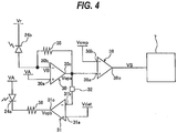
- FIG. 4 is a schematic diagram showing an arrangement of an electric circuit of the first optical sensor 24.
- the arrangement of the electric circuit of the first optical sensor 24 will be described below with reference to FIG. 4 .
- An arrangement of an electric circuit of the second optical sensor 25 is identical to the arrangement of the electric circuit of the first optical sensor 24, and its repetitive explanation will be omitted.
- a reverse bias voltage Vr is applied to the first light receiver 24b which is a photodiode.
- the first light receiver 24b receives the light from the first light emitter 24a which is an LED, thereby generating an electric current.
- the electric current generated from the first light receiver 24b is input to a negative input terminal 30b of a first operational amplifier 30.
- a voltage VA is input to a positive input terminal 30a of the first operational amplifier 30.
- a voltage Vopa which is converted from the electric current generated from the first light receiver 24b by a conversion resistor 35 using the voltage VA as a reference, is output (current-to-voltage conversion).
- the voltage Vopa output from the first operational amplifier 30 is input to a negative input terminal 31b of a second operational amplifier 31 through a delay circuit 32.
- a predetermined base voltage Vdet is input to a positive input terminal 31a of the second operational amplifier 31.
- the second operational amplifier 31 outputs, from a output terminal 31c of the second operational amplifier 31, a voltage Vopb which is a difference between the voltage Vopa input to the negative input terminal 31b and the base voltage Vdet input to the positive input terminal 31a.
- the voltage Vopb output from the output terminal 31c of the second operational amplifier 31 is converted by a conversion resistor 36 into an electric current, this electric current being applied to the first light emitter 24a.
- the voltage Vopa output from the output terminal of the first operational amplifier 30 is input to a positive input terminal 38a of a comparator 38.
- a voltage Vcmp which is a preset threshold value, is input to a negative input terminal 38b of the comparator 38.
- the comparator 38 compares the voltage Vopa input to the positive input terminal 38a and the voltage Vcmp input to the negative input terminal 38b with each other.
- the comparator 38 output a signal VS from its output terminal 38c.
- the signal VS is input to the arithmetic unit 7.
- the electric circuit shown in FIG. 4 includes a feedback circuit for automatically changing the amount of light emitted from the first light emitter 24a which is the photodiode, depending on the output electric current from the first light receiver 24b so that the output electric current from the first light receiver 24b which is the photodiode becomes constant.
- the first light receiver 24b which is the photodiode and receives the light emitted from the first light emitter 24a which is the LED, outputs a constant electric current at all times.
- the amount of light emitted from an LED differs depending on the environment (e.g., temperature and humidity) in which the LED is placed.
- the electric current output from a photodiode differs depending on the environment (e.g., temperature and humidity) in which the photodiode is placed.
- the amounts of light emitted from the LEDs are different from each other when the same electric current flows through the different LEDs that are of the same structure.
- the currents output from the photodiodes are different from each other when the different photodiodes, which are of the same structure, receive the same amount of light.
- the voltage Vopa output from the operational amplifier 30 varies depending on the environment in which the apparatus 1 for measuring coefficient of restitution is placed, and thus there is the possibility that a correct coefficient of restitution cannot be measured.
- the electric circuit shown in FIG. 4 it is necessary to adjust, in every measurement, the amount of light emitted from the first light emitter 24a and/or the output electric current from the first light receiver 24b.
- the amount of light emitted from the first light emitter 24a can automatically be adjusted so that the voltage Vopa output from the first operational amplifier 30 converges on the preset base voltage Vdet at all times. Accordingly, it is not necessary to adjust, in every measurement, the amount of light emitted from the first light emitter 24a and/or the output electric current from the first light receiver 24b. Similarly, it is not necessary to adjust, in each apparatus 1 for measuring coefficient of restitution, the amount of light emitted from the first light emitter 24a and/or the output electric current from the first light receiver 24b. Inasmuch as the arrangement of the electric circuit of the second optical sensor 25 is identical to the arrangement of the electric circuit of the first optical sensor 24, the identical advantages are available for the optical sensor 25.
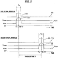
- FIG. 5 is a schematic diagram illustrating a method of measuring a passage time T1 taken after the indenter 2 has passed the first optical sensor 24 until the indenter 2 passes the second optical sensor 25.
- FIG. 5 is a schematic diagram illustrating a method of measuring the rebound speed of the indenter 2 which impacts against specimen 8 and rebounds therefrom.
- FIG. 5 shows in its upper area a graph representing the output voltage Vopa from the first operational amplifier 30 and the signal VS output from the comparator 38, which vary over time, of the first optical sensor 24.
- FIG. 5 shows in its lower area a graph representing the output voltage Vopa from the first operational amplifier 30 and the signal VS output from the comparator 38, which vary over time, of the second optical sensor 25.
- the indenter 2 which impacts against the specimen 8 and rebounds therefrom moves to the position where the first optical sensor 24 is disposed.
- the output voltage Vopa from the first operational amplifier 30 increases.
- the output voltage Vopa from the first operational amplifier 30 is plotted as a wave SA having a convex waveform shown in the upper area of FIG. 5 .
- the output voltage Vopa from the first operational amplifier 30 is input to the comparator 38 (see FIG. 4 ) and compared with the voltage Vcmp serving as the threshold value.
- the comparator 38 outputs the signal VS.
- the comparator 38 stops outputting the signal VS.
- a rectangular wave RA converted from the wave SA having the convex waveform by the comparator 38 is input to the arithmetic unit 7.
- the arithmetic unit 7 detects a point of time Ta when the signal VS is output from the comparator 38 and a point of time Tb when the outputting of the signal VS is stopped.
- the point of time Ta is a detection starting point of time when the arithmetic unit 7 starts detecting of the passage of indenter 2 at the first optical sensor 24, and the point of time Tb is a detection ending point of time when the arithmetic unit 7 ends detecting of the passage of indenter 2 at the first optical sensor 24.
- the arithmetic unit 7 calculates a time Td by halving a time Tc taken after the point of time Ta has been detected until the point of time Tb is detected.
- the time Tc corresponds to a time during which the arithmetic unit 7 is detecting the passage of indenter 2 at the first optical sensor 24.
- the indenter 2 further moves on to the position where the second optical sensor 25 is disposed.
- the indenter 2 blocks the light emitted from the second light emitter 25a of the second optical sensor 25, reducing the amount of light detected by the second light receiver 25b, the output voltage Vopa from the first operational amplifier 30 increases.
- the indenter 2 passes the second optical sensor 25, the blocked amount of light emitted from the second light receiver 25b gradually decreases and thereafter gradually increases. Therefore, because the amount of light detected by the second light receiver 25b gradually decreases and thereafter gradually increases, the output voltage Vopa from the first operational amplifier 30 is plotted as a wave SB having a convex waveform shown in the lower area of FIG. 5 .
- the output voltage Vopa from the first operational amplifier 30 is input to the comparator 38 (see FIG. 4 ) and compared with the voltage Vcmp as the threshold value.
- the comparator 38 outputs the signal VS.
- the comparator 38 stops outputting the signal VS.
- a rectangular wave RB converted from the wave SB having the convex waveform by the comparator 38 is input to the arithmetic unit 7.
- the arithmetic unit 7 detects a point of time Te when the signal VS is output from the comparator 38 and a point of time Tf when the outputting of the signal VS is stopped.
- the point of time Te is a detection starting point of time when the arithmetic unit 7 starts detecting of the passage of indenter 2 at the second optical sensor 25
- the point of time Tf is a detection ending point of time when the arithmetic unit 7 ends detecting of the passage of indenter 2 at the second optical sensor 25.
- the arithmetic unit 7 calculates a time Th by halving a time Tg taken after the point of time Te has been detected until the point of time Tf is detected.
- the time Tg corresponds to a time during which the arithmetic unit 7 is detecting the passage of indenter 2 at the second optical sensor 25.
- the arithmetic unit 7 determines the time between the point of time Td and the point of time Th, as a passage time T1 taken after the indenter 2 has passed the first optical sensor 24 until the indenter 2 passes the second optical sensor 25. In addition, the arithmetic unit 7 calculates the rebound speed of the indenter 2 by dividing the distance between the first optical sensor 24 and the second optical sensor 25 by the passage time T1.
- the time between the point of time Td and the point of time Th is used as the passage time T1 taken after the indenter 2 has passed the first optical sensor 24 until the indenter 2 passes the second optical sensor 25.
- the time between the point of time Td and the point of time Th is used as the passage time T1
- the impact speed of the indenter 2 is calculated by the arithmetic unit 7, using a similar method. Specifically, the arithmetic unit 7 calculates the impact speed by determining the passage time taken after the indenter 2 has passed the second optical sensor 25 until the indenter 2 passes the first optical sensor 24. The arithmetic unit 7 also calculates the coefficient of restitution which represents the ratio of the rebound speed to the impact speed.
- the second optical sensor 25 may be omitted, and thus the arithmetic unit 7 may calculate the impact speed and the rebound speed of the indenter 2, using only the first optical sensor 24.
- the arithmetic unit 7 may calculate the rebound speed of the indenter 2 by dividing the diameter of the indenter 2 by the time Tc between the point of time Ta (i.e., the detection starting point of time of the indenter 2 at the first optical sensor 24) and the point of time Tb (i.e., the detection ending point of time of the indenter 2 at the first optical sensor 24) in FIG. 5 .
- the arithmetic unit 7 can calculate the impact speed of the indenter 2, using only the first optical sensor 24.
- the size of the speed measuring body 23 can be reduced. Furthermore, since the first optical sensor 24 can be disposed near the surface of the specimen 8, it is possible to measure a correct coefficient of restitution.
- the holder 3 is inserted from the front end toward back end of the inner cylinder 13.
- the outer cylinder 12 has an outer cylinder flange 12c projecting radially outwardly of the outer cylinder 12
- the inner cylinder 13 has an inner cylinder flange 13c projecting radially outwardly of the inner cylinder 13.
- a holder flange member 40 is fixed to the outer circumferential surface of the holder 3.
- the holder flange member 40 includes a cylindrical static part 40a which is fixed to the outer circumferential surface of the holder 3 at its back end, and a projecting flange 40b which projects from the static part 40a radially outwardly of the holder 3.
- the inner cylinder 13 has a second elongated hole 13d passing through a side wall of the inner cylinder 13 and extending along a longitudinal direction of the inner cylinder 13.
- the projecting flange 40b of the holder flange member 40 extends through the second elongated hole 13d and projects outwardly of the outer circumferential surface of the inner cylinder 13.
- the apparatus 1 for measuring coefficient of restitution has a first return spring 43 disposed between the inner cylinder flange 13c and the outer cylinder flange 12c, and the first return spring 43 biases the inner cylinder flange 13c in a direction away from the outer cylinder flange 12c. Further, the apparatus 1 for measuring coefficient of restitution has a second return spring 44 disposed between the projecting flange 40b and the outer cylinder flange 12c, and the second return spring 44 biases the projecting flange 40b in a direction away from the outer cylinder flange 12c.
- a first guide rod 46 is fixed to the outer cylinder flange 12c, the first guide rod 46 extending through a first through hole 40c formed in the projecting flange 40b to pass through the projecting flange 40b.
- the first guide rod 46 extends through the inside of the second return spring 44.
- An anchor 48 is fixed to the first guide rod 46 for restricting the projecting flange 40b to move in a direction away from the outer cylinder flange 12c by a biasing force of the second return spring 44.
- a second guide rod 47 is fixed to the inner cylinder flange 13c, the second guide rod 47 extending through a second through hole 40d formed in the projecting flange 40b to pass through the projecting flange 40b.
- the outer cylinder flange 12c of the outer cylinder 12, the first guide rod 46, the second return spring 44, the holder flange member 40, and the anchor 48 constitutes a coupling mechanism 39 for coupling the holder 3 to the outer cylinder 12.
- FIG. 6 is a schematic view showing a state in which the indenter 2 is held in the holder 3 again after the coefficient of restitution has been measured.
- an operator pushes the outer cylinder 12 toward the inner cylinder 13 against the biasing force of the first return spring 43 until the hook 14a of the ejection lever 14 engages with the groove 15d formed on the outer surface of the striker 15.
- the holder 3 that is coupled to the outer cylinder 12 by the coupling mechanism 39 moves forwards in the indenter channel 23a of the speed measuring unit 6.
- the holder flange member 40 can also move in the forward direction of the apparatus 1 for measuring coefficient of restitution. Since the second return spring 44 applies its biasing force to the flange holder member 40 fixed to the holder 3, the holder 3 moves in the forward direction of the apparatus 1 for coefficient of restitution while the distance between the holder 3 and the outer cylinder 12 is maintained.
- the holder 3 moving in the forward direction of the apparatus 1 for coefficient of restitution moves forwards in the indenter channel 23 a formed in the speed measuring body 23 of the speed measuring unit 6 to reach the front end of the indenter channel 23 a, and as a result, the indenter 2 is held in the front end of the holder 3.
- the holder 3 When the outer cylinder 12 is pushed in the inner cylinder 13, the holder 3 is guided by the first guide rod 46. Similarly, when the outer cylinder 12 is pushed in the inner cylinder 13, the holder 3 is guided by the second guide rod 47. Therefore, the holder 3 is prevented from rotating with respect to the outer cylinder 12 and the inner cylinder 13.
- the indenter 2 can be held in the holder 3 again by a simple operation in which the outer cylinder 12 is pushed in the inner cylinder 13. Accordingly, a burden on the operator can be reduced when the coefficients of restitution are to be measured successively.
- an impactor (object) that impacts against the specimen 8 for measuring the coefficient of restitution is only the spherical indenter 2.
- the impactor that impacts against the specimen 8 does not include an indenter support to which the indenter 2 would be fixed.
- the mass of the impactor (object) that impacts against with the specimen 8 is greatly reduced, the mass effect occurring when the coefficient of restitution is to be measured is greatly reduced, thereby enabling the coefficient of restitution of the specimen to be correctly measured.
- the spherical indenter 2 is held in the holder 3, and ejected from the holder 3 toward the specimen 8 by the ejection mechanism 5. Therefore, since there is no limitation on the direction in which the indenter 2 is ejected, the test can be performed in a free direction. Furthermore, according to the apparatus 1 for measuring coefficient of restitution of this embodiment, the impact speed can be easily adjusted by moving the plug 18 forwards or backwards with respect to the outer cylinder 12.
- the apparatus 1 for measuring coefficient of restitution which is capable of greatly reducing the mass effect and performing the tests in a free direction, can measure coefficients of restitution of various specimens 8. For example, not only coefficients of restitution of metal materials, but also coefficients of restitution of foods such as chocolate and dried bonito or coefficients of restitution of non-metal materials such as ceramics, marble, and glass, can be measured. Further, the impactor that impacts against the specimen 8 is only the spherical indenter 2, and thus has a very small volume. Therefore, the heat capacity of the impactor is small. The indenter 2 contacts the specimen 8 instantaneously. As a result, the coefficient of restitution of a specimen 8 which is of high or low temperature can be correctly measured, because the amount of change in a surface temperature of the specimen due to the test is greatly reduced.
- the apparatus 1 for measuring coefficient of restitution according to the present embodiment can use indenters 2 having various diameters by appropriately selecting a size of the holder 3 and a diameter of the striker body 15a depending on the diameter of the indenter 2. Therefore, the apparatus 1 for measuring coefficient of restitution according to the present embodiment can use an indenter 2 having a very small diameter, so that the mass effect can further be reduced.
- the indenter 2 has as small a diameter as possible.
- the coefficient of restitution of a specimen 8 which has small irregularities on its surface is measured, the direction in which the indenter 2 is rebounded from the specimen 8 may greatly deviate from (be inclined with respect to) the direction in which the indenter 2 is ejected from the ejection mechanism 5.
- the reason of this is that the diameter of the indenter 2 is too small with respect to the size of the irregularities formed on the surface of the specimen 8. Therefore, in order to stabilize the direction in which the indenter 2 is rebound, while reducing the occurrence of the mass effect, it is preferable that the diameter of the indenter 2 is equal to or less than 5 mm.
- the diameter of the indenter 2 decreases, the burden on the operator for measuring the coefficient of restitution increases. For example, when the indenter 2 having a very small diameter is used, the operator is likely to lose the indenter 2. Therefore, from the viewpoint of working efficiency, it is preferable that the diameter of the indenter 2 is equal to or more than 0.5 mm. Furthermore, in order to reliably confirm a fracture or defect of the indenter 2 prior to the measurement of the coefficient of restitution, it is more preferable that the diameter of the indenter 2 is equal to or more than 2 mm. More specifically, the diameter of the indenter 2 is preferably in the range from 0.5 mm to 5 mm, and more preferably in the range from 2 mm to 5 mm.
- the speed measuring unit 6 of the apparatus 1 for measuring coefficient of restitution measures the impact speed and the rebound speed of the indenter 2 using the optical sensors 24, 25. Therefore, there is no limitation on the material of the indenter 2, and the indenter 2 may be made of a metal material such as cemented carbide or the like, or a non-metal material such as ceramics, diamond, or the like.
- the indenter 2 is a bearing ball made of alumina which is ceramics. Since the bearing ball made of alumina has high sphericity, the apparatus 1 for measuring coefficient of restitution can measure correct coefficients of restitution with high repeatability.
- the bearing ball made of alumina is inexpensive and easily commercially available.
- the speed measuring body 23 of the speed measuring unit 6 may have a shutter mechanism 50 which opens the opening of the indenter channel 23a in the speed measuring body 23 when the speed measuring unit 6 contacts the specimen 8, and which closes the opening of the indenter channel 23a in the speed measuring body 23 when the speed measuring unit 6 is separated from the specimen 8.
- FIG. 7 is a schematic cross-sectional view showing an example of the speed measuring body 23 that is provided with the shutter mechanism 50. As shown in FIG.
- the shutter mechanism 50 of this embodiment includes a door 51 disposed at the opening of the indenter channel 23 a, an opening/closing rod 54 whose front end projects from the speed measuring body 23, and a link mechanism 55 for converting movement of the opening/closing rod 54 into opening/closing movement of the door 51.
- the speed measuring body 23 of this embodiment is constructed by a first member 23b in which the indenter channel 23a is formed and the door 51 is disposed, and a second member 23c in which the opening/closing rod 54 is disposed.
- FIG. 8A is a view as viewed along arrows D in FIG. 7
- FIG. 8B is a cross-sectional view taken along line F-F of FIG. 8A
- FIG. 8C is a cross-sectional view taken along line G-G of FIG. 8B
- the door 51 of this embodiment has a first door 51a and a second door 51b which open and close the opening of the indenter channel 23a in the speed measuring body 23 by the link mechanism 55.
- the link mechanism 55 will be described later.
- FIG. 8A illustrates a state in which the first door 51a and the second door 51b abut against each other, and thus the opening of the indenter channel 23 a is closed.
- a first opening/closing guide 52 having a first arc-shaped surface 52a is fixed to a side surface of the first door 51a
- a second opening/closing guide 53 having a second arc-shaped surface 53a is fixed to a side surface of the second door 51b.
- the first arc-shaped surface 52a of the first opening/closing guide 52 and the second arc-shaped surface 53a of the second opening/closing guide 53 face each other.
- the first opening/closing guide 52 is pivotably secured to the first member 23b by a first opening/closing shaft 56.
- first opening/closing guide 52 can pivot about the first opening/closing shaft 56, and as a result, the first door 51a fixed to the first opening/closing guide 52 can pivot about the first opening/closing shaft 56.
- the second opening/closing guide 53 is pivotably secured to the first member 23b by a second opening/closing shaft 57.
- the second opening/closing guide 53 can pivot about the second opening/closing shaft 57, and as a result, the second door 51b fixed to the second opening/closing guide 53 can pivot about the second opening/closing shaft 57.
- a first receiving portion 51c (see FIG. 8B ) is formed, in which a first sloping surface 51d with a circular-arc-shape is formed.
- a second receiving portion 51f is formed, in which a second sloping surface 51e with a circular-arc shape is formed.
- FIG. 9A is a view as viewed along arrows E in FIG. 7
- FIG. 9B is a cross-sectional view taken along line H - H of FIG. 9A
- one end of an opening/closing spring 58 is fixed to the back end of the opening/closing rod 54
- the other end of the opening/closing spring 58 is fixed to the second member 23c.
- the front end of the opening/closing rod 54 projects forwards from the front end of the second member 23c.
- a first protrusion 54a and a second protrusion 54b which are cylindrical in shape, are formed on a side surface of the opening/closing rod 54.
- the first protrusion 54a is positioned forwardly of the second protrusion 54b on the opening/closing rod 54.
- the first protrusion 54a and the second protrusion 54b project from the side surface of the opening/closing rod 54 toward the first member 23b.
- the link mechanism 55 of the shutter mechanism 50 is constructed by the first opening/closing guide 52, the second opening/closing guide 53, the first protrusion 54a and the second protrusion 54b formed on the opening/closing rod 54, and the opening/closing spring 58.
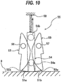
- FIG. 10 is a schematic view showing a state in which the first door 51a and the second door 51b are pivoted in directions away from each other by the link mechanism 55, and thus the opening of the indenter channel 23a is opened.
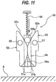
- FIG. 11 is a schematic view showing a state in which the first door 51a and the second door 51b are brought into abutment against each other by the link mechanism 55, and thus the opening of the indenter channel 23a is closed.
- the first protrusion 54a formed on the opening/closing rod 54 contacts the first arc-shaped surface 52a of the first opening/closing guide 52 and the second arc-shaped surface 53 a of the second opening/closing guide 53, thereby rotating the first opening/closing guide 52 and the second opening/closing guide 53 respectively, about the first opening/closing shaft 56 and the second opening/closing shaft 57 in directions to separate the first door 51a and the second door 51b away from each other.
- the opening of the indenter channel 23a of the speed measuring body 23 is opened, allowing the indenter 2 to impact against the surface of the specimen 8.
- the opening/closing rod 54 moves forwards until the front end of the opening/closing rod 54 projects from the front end of the speed measuring body 23 with the spring force of the opening/closing spring 58.
- the second protrusion 54b formed on the opening/closing rod 54 contacts the first arc-shaped surface 52a of the first opening/closing guide 52 and the second arc-shaped surface 53a of the second opening/closing guide 53, thereby rotating the first opening/closing guide 52 and the second opening/closing guide 53 respectively, about the first opening/closing shaft 56 and the second opening/closing shaft 57 in directions to bring the first door 51a and the second door 51b into abutment against each other.
- the opening of the indenter channel 23a of the speed measuring body 23 is closed, housing the indenter 2 in the internal space formed by the first receiving portion 51c and the second receiving portion 51f (see FIG. 8C ).
- the indenter 2 is guided by the first sloping surface 51d of the first receiving portion 51 c and the second sloping surface 51e of the second receiving portion 51f, preventing the indenter 2 from being pinched by the first door 51a and the second door 51b.
- the opening of the indenter channel 23a is opened, only when the speed measuring body 23 contacts the specimen 8.
- the opening of the indenter channel 23a is closed. Therefore, a loss of the indenter 2 ejected from the ejection mechanism 5 is effectively prevented, so that the burden on the operator can be reduced.
- FIG. 12 is a schematic view showing the speed measuring unit 6 according to another embodiment.
- the speed measuring unit 6 shown in FIG. 12 has a third passage sensor 26 in addition to the first passage sensor 24 and the second passage sensor 25.
- the "passage sensor” collectively refers to sensors capable of detecting the passage of an object, and includes an optical sensor or a magnetic sensor, for example.
- the embodiment in which the first passage sensor 24, the second passage sensor 25, and the third passage sensor 26 are optical sensors, will be described below.
- the first optical sensor 24, the second optical sensor 25, and the third optical sensor 26 are arrayed along the indenter channel 23a.
- the first optical sensor 24 is positioned forwardly of the second optical sensor 25 and the third optical sensor 26 in the speed measuring body 23, and the second optical sensor 25 is positioned forwardly of the third optical sensor 26 in the speed measuring body 23.
- the third optical sensor 26 is identical in structure to the first optical sensor 24 and the second optical sensor 25. Specifically, the third optical sensor 26 has a third light emitter 26a for emitting light into the indenter channel 23a and a third light receiver 26b for receiving the light emitted from the third light emitter 26a.
- the third light emitter 26a is an LED
- the third light receiver 26b is a photodiode.
- the arrangement of an electric circuit of the third optical sensor 26 is identical to the arrangement of the electric circuit of the first optical sensor 24 described with reference to FIG. 4 . Specifically, the amount of light emitted from the third light emitter 26a can automatically be adjusted so that the voltage Vopa output from the first operational amplifier 30 in the electric circuit of the third optical sensor 26 converges on the preset base voltage Vdet at all times.
- the apparatus 1 for measuring coefficient of restitution 1 are able to perform tests in free directions.
- the indenter 2 can be ejected upwardly or downwardly. If the indenter 2 is ejected in different directions, gravitational forces in different directions act on the indenter 2. Therefore, depending on the direction in which the ejected indenter 2 is ejected, small errors may be produced in the measured coefficients of restitution. In particular, the gravitational force tends to have a greater effect when the impact speed and the rebound speed of the indenter 2 are low.
- the coefficient of restitution using, as the impact speed, the speed of the indenter 2 at the instant at which the indenter 2 impacts against the surface of the specimen 8, and using, as the rebound speed, the speed of the indenter 2 at the instant at which the indenter 2 is rebounded from the surface of the specimen 8.
- a method of determining, through calculations, the impact speed of the indenter 2 at the instant at which the indenter 2 impacts against the specimen 8, and the rebound speed of the indenter 2 at the instant at which the indenter 2 is rebound from the specimen 8 will be described below with reference to FIG. 13 .
- FIG. 13 is an explanatory diagram illustrating a method of determining, through calculations, the impact speed of the indenter 2 at the instant at which the indenter 2 impacts against the surface of the specimen 8 and the rebound speed of the indenter 2 at the instant at which the indenter 2 is rebounded from the specimen 8.
- a point Ps represents the surface of the specimen 8
- a point P1 represents the position of the first optical sensor 24
- a point P2 represents the position of the second optical sensor 25
- a point P3 represents the position of the third optical sensor 26.
- the speed of the indenter 2 passing the point P3 i.e., the third optical sensor 26
- the speed of the indenter 2 passing the point P2 i.e., the second optical sensor 25
- the speed of the indenter 2 passing the point P1 i.e., the first optical sensor 24
- the speed of the indenter 2 at the instant at which the indenter 2 reaches the point Ps is represented by vs.
- the average speed between the point P3 and the point P2 is represented by v23
- the average speed between the point P2 and the point P1 is represented by v12
- the average speed between the point P3 and the point P1 is represented by v13
- a distance from the point P3 to the point P2 is represented by L23
- a distance from the point P2 to the point P1 is represented by L12
- a distance from the point P3 to the point P1 is represented by L13
- a distance from the point P3 to the point Ps is represented by Ls.
- the controller 7 measures, according to the method described with reference to FIG.
- the average speed v23 between the point P3 and the point P2 can be calculated from the time T23 measured by the controller 7 and the known L23 according to the following equation (1).
- v 23 L 23 / T 23
- the average speed v12 can be calculated according to the following equation (2), and the average speed v13 can be calculated according to the following equation (3).
- v 12 L 12 / T 12
- v 13 L 13 / T 13
- the arithmetic unit 7 Since the arithmetic unit 7 has obtained the speed v23, the speed v12, and the speed v13 according to the above-described equations (1), (2), (3), the arithmetic unit 7 can calculate the speed v1, the speed v2, and the speed v3 according to the equation (7), the equation (8), and the equation (9). As a result, the arithmetic unit 7 can calculate the acceleration ⁇ of the indenter 2 according to the equation (10).
- the impact speed vs at the instant at which the indenter 2 impacts against the point Ps can be determined from the following equation (11) or equation (12).
- vs v 3 2 + 2 Ls ⁇ ⁇ 1 / 2
- vs v 3 ⁇ 1 + v 1 / v 3 2 ⁇ 1 Ls / L 13 ) 1 / 2
- the arithmetic unit 7 can calculate the impact speed vs at the instant at which the indenter 2 impacts against the surface of the specimen 8.
- the point Ps represents the surface of the specimen 8
- the point P1 represents the position of the first optical sensor 24
- the point P2 represents the position of the second optical sensor 25
- the point P3 represents the position of the third optical sensor 26.
- the indenter 2 which has been rebounded from the surface of the specimen 8 passes the point P1, the point P2, and the point P3 in this order.
- the speed of the indenter 2 passing the point P1 (i.e., the first optical sensor 24) after being rebounded from the point Ps is represented by v1'
- the speed of the indenter 2 passing the point P2 (i.e., the second optical sensor 25) after being rebounded from the point Ps is represented by v2'
- the speed of the indenter 2 passing the point P3 (i.e., the third optical sensor 26) after being rebounded from the point Ps is represented by v3'.
- the average speed between the point P1 and the point P2 is represented by v12'
- the average speed between the point P2 and the point P3 is represented by v23'
- the average speed between the point P1 and the point P3 is represented by v13'.
- the distance from the point P1 to the point P2 is represented by L12
- the distance from the point P2 to the point P3 is represented by L23
- the distance from the point P1 to the point P3 is represented by L13
- the distance from the point Ps to the point P3 is represented by Ls.
- the controller 7 measures, according to the method described with reference to FIG.
- the average speed v12' between the point P1 and the point P2 can be calculated from the time T12' measured by the controller 7 and the known L12 according to the following equation (13).
- v 12 ′ L 12 / T 12 ′
- the average speed v23' can be calculated according to the following equation (14), and the average speed v13' can be calculated according to the following equation (15).
- v 23 ′ L 23 / T 23 ′
- v 13 ′ L 13 / T 13 ′
- the arithmetic unit 7 Since the arithmetic unit 7 has obtained the speed v12', the speed v23', and the speed v13' from the above-described equations (13), (14), and (15), the arithmetic unit 7 can calculate the speed v1', the speed v2', and the speed v3' according to the equation (19), the equation (20), and the equation (21). As a result, the arithmetic unit 7 can calculate the acceleration ⁇ ' of the indenter 2 rebounded from the point Ps according to the equation (22).
- the rebound speed vs' of the indenter 2 at the instance at which it has rebounded from the point Ps can be determined from the following equation (23) or equation (24).
- vs ′ v 1 ′ 2 + 2 Ls ⁇ ⁇ 1 / 2
- vs ′ v 1 ′ ⁇ 1 + v 3 ′ / v 1 ′ 2 ⁇ 1 ⁇ L 13 ⁇ Ls / L 13 1 / 2
- the arithmetic unit 7 can calculate the rebound speed vs' at the instance at which the indenter 2 is rebounded from the surface of the specimen 8.
- the arithmetic unit 7 is capable of determined, through calculations, the impact speed vs of the indenter 2 at the instant at which the indenter 2 impacts against the specimen 8, and the rebound speed vs' of the indenter 2 at the instant at which the indenter 2 is rebounded from the surface of the specimen 8.
- the arithmetic unit 7 calculates the coefficient of restitution based on the impact speed vs at the instant at which the indenter 2 impacts against the specimen 8 and the rebound speed vs' at the instant at which the indenter 2 is rebounded from the surface of the specimen 8, the arithmetic unit 7 can obtain the coefficient of restitution in which the effect of the gravitational force acting on the indenter 2 is removed.
- FIG. 14 is a schematic view showing the speed measuring unit 6 according to still another embodiment.
- the first light emitter 24a and the first light receiver 24b of the first optical sensor 24, and the second light emitter 25a and the second light receiver 25b of the second optical sensor 25 of the speed measuring unit 6 shown in FIG. 14 are disposed in the arithmetic unit 7.
- the first optical sensor 24 and the second optical sensor 25 are disposed in the arithmetic unit 7.
- the speed measuring body 23 has four through holes 23d, 23e, 23f, and 23g formed therein, which extend from side faces of the speed measuring body 23 to wall surfaces of the indenter channel 23a. Although only the through holes 23d, 23f are illustrated in FIG. 14 , the through hole 23e is formed in a position facing the through hole 23d, and the through hole 23 g is formed in a position facing the through hole 23f.
- a first optical fiber 60 extending from the first light emitter 24a is fitted in the through hole 23d, so that the light emitted by the first light emitter 24a passes through the first optical fiber 60 and is emitted into the indenter channel 23 a.
- a second optical fiber 61 extending from the first light receiver 24b is fitted in the through hole 23e, so that the light emitted by the first light emitter 24a passes through the second optical fiber 61 and is received by the first light receiver 24b.
- the first light emitter 24a of the first optical sensor 24 emits the light through the first optical fiber 60 into the indenter channel 23a
- the first light receiver 24b of the first optical sensor 24 receives the light emitted into the indenter channel 23a through the second optical fiber 61.
- a third optical fiber 62 extending from the second light emitter 25a is fitted in the through hole 23f, so that the light emitted by the second light emitter 25a passes through the third optical fiber 62 and is emitted into the indenter channel 23a.
- a fourth optical fiber 63 extending from the second light receiver 25b is fitted in the through hole 23g, so that the light emitted by the second light emitter 25a passes through the fourth optical fiber 63 and is received by the second light receiver 25b.
- the second light emitter 25a of the second optical sensor 25 emits the light through the third optical fiber 62 into the indenter channel 23a, and the second light receiver 25b of the second optical sensor 25 receives the light emitted into the indenter channel 23a through the fourth optical fiber 63.
- the size of the speed measuring body 23 can be reduced. Therefore, the speed measuring body 23 can be inserted into a small gap. For example, as shown in FIG. 14 , it is possible to measure the coefficient of restitution of a bottomland 65b formed between two adjacent teeth 65a, 65b of a gear 65.
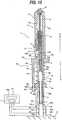
- FIG. 15 is a schematic cross-sectional view showing the apparatus 1 for measuring coefficient of restitution according to another embodiment.
- a piston rod 19 is used as an indenter pushing member.
- the piston rod 19 applies an air pressure to the indenter 2 held in the holder 3, ejecting the indenter 2 from the holder 3 toward the material 8 by use of this air pressure.
- Structures of the apparatus 1 for measuring coefficient of restitution according to the present embodiment other than the piston rod 19 are identical to those of the apparatus 1 for measuring coefficient of restitution described above, and their repetitive descriptions are omitted.
- the piston rod 19 includes a cylindrical rod body 19a, a cylindrical rod support 19b having a diameter greater than the diameter of the rod body 19a, and a disk-shaped piston head 19e fixed to the front end of the rod body 19a.
- the rod body 19a has its back end embedded in the front end of the rod support 19b, so that the rod body 19a is fixed to the rod support 19b.
- the central axis of the rod body 19a is in alignment with the central axis of the body support 19b.
- the piston head 19e has its outer circumferential surface slidable against the inner circumferential surface of the inner cylinder 13.
- the central axis of the piston head 19e is in alignment with the central axis of the rod body 19a.
- the front end of the biasing spring 16 is inserted into a guide hole 19c formed in the rod support 19b.
- the guide hole 19c extends from the back end toward front end of the rod support 19b, and the central axis of the guide hole 19c is in alignment with the central axis of the rod support 19b.
- a plug 18 that closes the opening of the outer cylinder 12 is fixed, and the back end of the biasing spring 16 is supported by the plug 18.
- the plug 18 according to the present embodiment has a cylindrical shape, and the screw thread is formed on the outer circumferential surface of the plug 18.
- the opening formed on the back end of the outer cylinder 12 is constructed as the threaded hole into which the screw thread formed on the outer circumferential surface of the plug 18 is screwed.
- the screw thread formed on the plug 18 engages with the threaded hole, thereby securing the plug 18 to the outer cylinder 12.
- the biasing spring 16 is disposed between the outer cylinder 12 and the piston rod 19. As described above with reference to FIG. 6 , the biasing spring 16 is compressed by movement of the outer cylinder 12, thereby allowing the biasing force to be applied to the piston rod 19. As shown in FIG. 15 , when the biasing spring 16 is compressed, the biasing spring 16 applies the biasing force for moving the piston rod 19 in the forward direction of the ejection mechanism 5, to the piston rod 15. This position of the piston rod 19 is an ejection position of the piston rod 19.
- An annular groove 19d extending along a circumferential direction of the rod support 19b is formed on the outer surface of the rod support 19b.
- the groove 19d may be formed on a part of the outer surface of the rod support 19b.
- the ejection lever 15 is fixed to the outer surface of the outer cylinder 12, the ejection lever 15 having the hook 14a that can engage with the groove 19d when the piston rod 19 is in the ejected position shown in FIG. 15 .
- the ejection lever 14 has the through hole, and the rotational shaft 17 which is secured to a bracket (not shown) extending radially outwardly from the outer surface of the outer cylinder 12, is inserted into this through hole.
- the ejection lever 14 is mounted to the outer cylinder 12 so as to be able to pivot around the rotational shaft 17.
- the outer cylinder 12 has the through hole 12b which penetrates through the side wall of the outer cylinder 12
- the inner cylinder 13 has the first elongated hole 13e which penetrates through the side wall of the inner cylinder 13 and extends along a longitudinal direction of the inner cylinder 13.
- the hook 14a of the ejection lever 14 passes through the through hole 12b of the outer cylinder 12 and the first elongated hole 13e of the inner cylinder 13 to engage with the groove 19d of the piston rod 19.
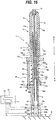
- FIG. 16 is a schematic cross-sectional view showing a state in which the piston rod 19 is pushed out in the forward direction of the ejection mechanism 5 with use of the spring force of the biasing spring 16 when the hook 14a of the ejection lever 14 disengages from the groove 19d of the piston rod 19.
- the piston rod 19 that has been pushed out in the forward direction of the ejection mechanism 5 collides with the stopper 20, which has a hollow cylindrical shape and is fixed to the inner circumferential surface of the inner cylinder 13, and as a result, the forward movement of the piston rod 19 is restricted.
- the stopper 20 which has a hollow cylindrical shape and is fixed to the inner circumferential surface of the inner cylinder 13, and as a result, the forward movement of the piston rod 19 is restricted.
- the stopper 20 has a hollow cylindrical shape and is fixed to the inner circumferential surface of the inner cylinder 13, and as a result, the forward movement of the piston rod 19 is restricted.
- the stopper 20 has a hollow cylindrical shape and is fixed to the inner circum
- the piston head 19e compresses air that is present in a space extending from the piston head 19e to the indenter 2.
- the pressure of the compressed air acts on the indenter 2 held in the front end of the holder 3, and the indenter 2 is ejected toward the specimen 8 by this pressure of the compressed air. Since movement of the piston head 19e is restricted by the stopper 20, the piston head 19e does not contact the indenter 2. In this manner, the indenter 2 may be ejected toward the specimen 8 by the air pressure acting on the indenter 2.
- the length of the biasing spring 16 can be adjusted by moving the plug 18 supporting the back end of the biasing spring 16 forwards or backwards relative to the outer cylinder 12. Therefore, since the biasing force applied from the biasing spring 16 to the piston rod 19 can be adjusted, the impact speed of the indenter 2 ejected by the air which is compressed by the piston rod 19 can be adjusted.
- the material of the indenter 2 and the impact speed of the indenter 2 are constant.
- the apparatus 1 for measuring coefficient of restitution according to the present embodiment can easily adjust the impact speed of the indenter 2.
- FIG. 17 is a plan view of the standard block used in the experiment, and coefficients of restitution were measured at five measurement points Pa, Pb, Pc, Pd, and Pe shown in FIG. 17 .
- the measurement point Pc is positioned at the center of the standard block, and the measurement points Pa, Pe are positioned at outer circumferential areas of the standard block.
- the measurement point Pb is positioned between the measurement point Pa and the measurement point Pc, and the measurement point Pd is positioned between the measurement point Pc and the measurement point Pe.
- the D-type Shore hardness test and the Leeb hardness test were carried out on the same measurement points Pa, Pb, Pc, Pd, and Pe.
- the indenter 2 used in the experiment is a bearing ball made of alumina and having a diameter of 2 mm.
- the mass of the indenter 2 was 0.055 g.
- the indenter 2 was ejected vertically downwardly.
- the length of the biasing spring 16 was adjusted so that the impact speed of the indenter 2 measured using the first optical sensor 24 and the second optical sensor 25 would be 10 m/s.
- the length of the biasing spring 16 can be adjusted by moving the plug 18 forwards or backwards relative to the outer cylinder 12.
- FIG. 18A is a graph indicating coefficients of restitution in the case where the standard blocks fixed to the steel anvil were tested by the apparatus 1 for measuring coefficient of restitution
- FIG. 18B is a graph indicating coefficients of restitution in the case where the standard blocks fixed to the wood anvil were tested by the apparatus 1 for measuring coefficient of restitution.
- FIGS. 18A and 18B it was confirmed that there were no differences in the coefficients of restitution measured by the apparatus 1 for measuring coefficient of restitution between the case where the standard blocks were fixed to the steel anvil and the case where the standard blocks were fixed to the wood anvil, and that the coefficients of restitution were not affected by the mass effect. It was also confirmed that the same coefficients of restitution were measured at all of the five measurement points Pa, Pb, Pc, Pd, and Pe.
- FIG. 19A is a graph indicating Shore hardnesses in the case where the standard blocks fixed to the steel anvil were tested by the D-type Shore hardness tester
- FIG. 19B is a graph indicating Shore hardnesses in the case where the standard blocks fixed to the wood anvil were tested by the D-type Shore hardness tester.
- a hammer including an indenter made of diamond and an indenter support member to which the indenter is secured at its front end drops from a predetermined drop height onto the standard block, and a rebound height reached by the hammer when it has been rebounded, is measured.
- the Shore hardness is obtained by multiplying the ratio of the rebound height to the drop height by a predetermined proportionality constant.
- the mass of the hammer used in the D-type Shore hardness test was 36.2 g (including the mass of the indenter) and the drop height was 19 mm.
- FIG. 20A is a graph indicating Leeb hardnesses in the case where the standard blocks fixed to the steel anvil were tested by the Leeb hardness tester
- FIG. 20B is a graph indicating Leeb hardnesses in the case where the standard blocks fixed to the wood anvil were tested by the Leeb hardness tester.
- the Leeb hardness test is a hardness testing method in which an impact body including an indenter and an indenter support member to which the indenter is secured at its front end, is ejected toward a specimen by a spring, and an impact speed of the impact body before impacting against the specimen and a rebound speed of the impact body when impacting against the specimen and rebounded therefrom are measured.
- the rebound speed of the impact body with respect to the impact speed of the impact body before impacting against the specimen is measured as a coefficient of restitution.
- the Leeb hardness is obtained by multiplying the coefficient of restitution by a predetermined proportionality constant.
- the mass of the impact body used in the Leeb hardness test was 5.45 g (including the mass of the indenter), and the impact speed before the impact body impact against the specimen was 2.1 m/s.
- the Leeb hardnesses of the standard blocks fixed to the wood anvil were smaller than the Leeb hardnesses of the standard blocks fixed to the steel anvil. Therefore, it was confirmed that even in the Leeb hardness test, the mass effect due to the impact body had an effect on the measured hardnesses. Furthermore, a phenomenon that the measured Leeb hardnesses were gradually smaller from the central measurement point toward the measurement points in the peripheral areas was confirmed.
- a lid may be fixed to the front end of the speed measuring body 23 of the speed measuring unit 6, and the lid may have a lid through hole which is connected to the indenter channel 23a formed in the speed measuring body 23.
- FIG. 21A is a cross-sectional view showing an example of the lid 70 fixed to the front end of the speed measuring body 23, and FIG. 21B is a view as viewed along arrow I in FIG. 21A . Structures of the present embodiment other than the lid 70 are identical to those of the embodiments described above, and their repetitive descriptions are omitted.
- the lid 70 fixed to the front end of the speed measuring body 23 has a lid through hole 71 which is connected to the indenter channel 23a of the speed measuring body 23.
- the lid through hole 71 has a hollow cylindrical shape extending from a front face 70a to a rear face 70b of the lid 70.
- the diameter D of the lid through hole 71 is constant from the front face 70a to the rear face 70b.
- a central axis of the lid through hole 71 is in alignment with the central axis of the indenter channel 23a.
- the lid through hole 71 has a diameter D smaller than the diameter d of the indenter 2 (i.e., D ⁇ d). Therefore, the lid 70 prevents the indenter 2 from being expelled out of the apparatus 1 for measuring coefficient of restitution, because the indenter 2 cannot pass fully through the lid through hole 71.
- FIG. 22 is a schematic view showing an example of a distribution of impact points S where the indenter 2 impacts against the surface of the specimen 8. As shown in FIG.
- the lid through hole 71 has a diameter D smaller than the diameter d of the indenter 2 so that the indenter 2 is not expelled out of the apparatus 1 for measuring coefficient of restitution.
- the lid 70 may be deformed. Therefore, in order to reliably prevent the indenter 2 ejected from the ejection mechanism 5 from colliding with the lid 70, the lid through hole 71 preferably has a diameter D that is as large as possible within the range smaller than the diameter d of the indenter 2.
- the diameter D of the lid through hole 71 is preferably 0.5 times the diameter d of the indenter 2 or greater, and more preferably 0.7 times the diameter d of the indenter 2 or greater, or much more preferably be 0.9 times the diameter d of the indenter 2 or greater.
- the lid 70 is fastened to the speed measuring body 23 by three screws (fasteners) 73.
- the screws 73 engage with threaded holes (not shown) formed in the speed measuring body 23, so that the lid 70 is fastened to the speed measuring body 23.
- the screws 73 are screwed into the threaded holes formed in the speed measuring body 23 so as not to project from the front face 70a of the lid 70.
- the number of screws 73 may be less than three or more than three. Instead of the screws 73, hexagonal bolts may be used as fasteners for fastening the lid 70 to the speed measuring body 23.
- the lid through hole 71 allows a part of the indenter 2 to pass through the lid 70, but the indenter 2 in its entirety cannot pass through the lid 70.
- the lid 70 having such lid through hole 71 is simpler in structure than the shutter mechanism 50, and thus can be manufactured less expensively than the shutter mechanism 50. As a result, a manufacturing cost of the apparatus 1 for measuring coefficient of restitution can be reduced. Further, since the diameter D of the lid through hole 71 is smaller than the diameter d of the indenter 2, the indenter 2 ejected from the ejection mechanism 5 is reliably prevented from being expelled out of the speed measuring body 23.
- the indenter 2 when the indenter 2 is ejected from the ejection mechanism 5 in a state in which the front face 70a of the lid 70 is not placed in contact with the surface of the specimen 8, the indenter 2 does not collide with the operator in the vicinity of the apparatus 1 for measuring coefficient of restitution. Accordingly, the safety of operator is increased. Furthermore, a loss of the indenter 2 is effectively prevented, so that the burden on the operator is reduced.
- the speed measuring body 23 may have vent holes 75 extending from side surfaces of the speed measuring body 23 to the indenter channel 23 a.
- the vent holes 75 provided with the speed measuring body 23 prevent air in the indenter channel 23 a from being compressed by the indenter 2 passing through the indenter channel 23a. If air in the indenter channel 23a is compressed by the indenter 2 ejected from the ejection mechanism 5, the impact speed of the indenter 2 may be reduced, and the rebound speed of the indenter 2 may be increased.
- the vent holes 75 provided with the speed measuring body 23 enables the indenter channel 23a to communicate with the exterior of the speed measuring body 23.
- the vent holes 75 are provided at positions close to the front end of the speed measuring body 23. Accordingly, a more correct coefficient of restitution of the specimen 8 can be measured, because air in the indenter channel 23a is not compressed by the indenter 2 passing through the indenter channel 23 a.
- the number of vent holes 75 may be one, or three or more.
- a cross-sectional shape of the vent hole 75 can be determined arbitrarily.
- the vent holes 75 may have a circular cross-sectional shape or a rectangular cross-sectional shape.
- the size of the vent hole 75 is preferably smaller than the size of the indenter 2. In this case, the indenter 2 is prevented from being expelled out of the speed measuring body 1 through the vent holes 75.
- FIG. 23 is a cross-sectional view showing a modified example of the lid 70 fixed to the front end of the speed measuring body 23.
- a wall surface 71 a of the lid through hole 71 in the lid 70 is formed in a curved surface.
- a minimum diameter D min of the lid through hole 71 is represented by a diameter of the lid through hole 71 that is open at the front face 70a of the lid 70.
- the minimum diameter D min of the lid through hole 71 is smaller than the diameter d of the indenter 2. Therefore, since the indenter 2 cannot pass fully through the lid through hole 71, the lid 70 prevents the indenter 2 from being expelled out of the apparatus 1 for measuring coefficient of restitution.
- the minimum diameter D min of the lid through hole 71 is at least 0.2 times the diameter d of the indenter 2. Therefore, the indenter 2 ejected from the ejection mechanism 5 can impact against the surface of the specimen 8 without colliding with the lid 70.
- the wall surface 71a formed in a curved surface effectively prevents the indenter 2 ejected from the ejection mechanism 5 from colliding with the lid 70.
- the minimum diameter D min of the lid through hole 71 is preferably 0.5 times the diameter d of the indenter 2 or greater, and more preferably 0.7 times the diameter d of the indenter 2 or greater, or much more preferably 0.9 times the diameter d of the indenter 2 or greater.
- FIG. 24 is a cross-sectional view showing another modified exxample of the lid 70 fixed to the front end of the speed measuring body 23.
- the front end of the speed measuring body 23 has a hollow cylindrical portion 23h
- the indenter channel 23a extends to the front end of the hollow cylindrical portion 23h.
- the lid 70 has a hollow cylindrical step 70c into which the hollow cylindrical portion 23h is fitted.
- the lid through hole 71 according to the present embodiment has a hollow cylindrical shape
- the wall surface 71a of the lid through hole 71 may be formed in a curved surface having a constant radius rc of curvature, as shown in FIG. 23 .
- the central axis of the lid through hole 71 can easily be aligned with the central axis of the indenter channel 23a by fitting the step 70c of the lid 70 into the hollow cylindrical portion 23h of the speed measuring body 23.
- the vent holes 75 extend from side surfaces of the lid 70 to the indenter channel 23a.
- the vent holes 75 pass through the hollow cylindrical portion 23h of the speed measuring body 23.
- the vent holes 75 may extend from side surfaces of the lid 70 through the hollow cylindrical portion 23h to the indenter channel 23 a.
- the indenter 2 used in a first experiment was a bearing ball made of alumina, and the diameter d of the indenter 2 was 3 mm.
- the diameter D of the lid through hole 71 was 2.8 mm. Therefore, the lid through hole 71 had a diameter D that was 0.93 times the diameter d of the indenter 2.
- the diameter da of the indenter channel 23a was 5 mm. Therefore, the indenter channel 23a had a diameter da that was 1.67 times the diameter d of the indenter 2.
- the length of the biasing spring 16 was adjusted so that the impact speed of the indenter 2 would be 10 m/s.
- the indenter 2 used in a second experiment was a bearing ball made of alumina, and the diameter d of the indenter 2 was 3 mm.
- the diameter D of the lid through hole 71 was 2.8 mm. Therefore, the lid through hole 71 had a diameter D that was 0.93 times the diameter d of the indenter 2.
- the diameter da of the indenter channel 23a was 4 mm. Therefore, the indenter channel 23a had a diameter da that was 1.33 times the diameter d of the indenter 2.
- the length of the biasing spring 16 was adjusted so that the impact speed of the indenter 2 would be 10 m/s.
- the indenter 2 used in a third experiment was a bearing ball made of alumina, and the diameter d of the indenter 2 was 5 mm.
- the diameter D of the lid through hole 71 was 4.7 mm. Therefore, the lid through hole 71 had a diameter D that was 0.94 times the diameter d of the indenter 2.
- the diameter da of the indenter channel 23a was 7 mm. Therefore, the indenter channel 23a had a diameter da that was 1.4 times the diameter d of the indenter 2.
- the length of the biasing spring 16 was adjusted so that the impact speed of the indenter 2 would be 10 m/s.
- coefficients of restitution of the same standard blocks were measured using the apparatus 1 for measuring coefficient of restitution with the shutter mechanism 50 mounted in the speed measuring body 23.
- the indenter 2 used in the experiments for obtaining the reference values was a bearing ball made of alumina, and the diameter d of the indenter 2 was 3 mm.
- the diameter da of the indenter channel 23 a was 5 mm. Therefore, the indenter channel 23 a had a diameter da that was 1.67 times the diameter d of the indenter 2.
- the length of the biasing spring 16 was adjusted so that the impact speed of the indenter 2 would be 10 m/s.
- Coefficients of restitution obtained in the first experiment, the second experiment, and the third experiment, and coefficients of restitution measured as reference values are indicated in Table 1.
- the coefficients of restitution and the reference values indicated in Table 1 are average values of seven coefficients of restitution measured at different positions on the specimens.
- the coefficients of restitution obtained in the first experiment, the second experiment, and the third experiment are essentially the same as the coefficients of restitution measured as reference values. Therefore, the apparatus 1 for measuring coefficient of restitution with the lid 70 fixed to the front end of the speed measuring body 23 can measure coefficients of restitution without being affected by the mass effect occurring in a conventional rebound hardness tester. Further, it was confirmed from the results of the first experiment and the results of the second experiment that even though the indenters 2 having different diameters d are used, the same coefficients of restitution can be obtained by fixing the impact speed of the indenter 2 to a constant.
- the coefficients of restitution obtained in the second experiment are slightly smaller than the coefficients of restitution obtained in the first experiment and the coefficients of restitution obtained in the third experiment.
- the coefficients of restitution obtained in the first experiment and the coefficients of restitution obtained in the third experiment are the same as the reference values.
- the reason of this is considered to be the fact that the wall surface of the indenter channel 23a and the outer surface of the indenter 2 are too close to each other. Therefore, in order to obtain more correct coefficients of restitution, it is preferred that the indenter channel 23a has a diameter da which is 1.4 times the diameter d of the indenter 2 or greater. Also in the apparatus 1 for measuring coefficient of restitution with the shutter mechanism 50 mounted in the speed measuring body 23, it is preferred that the indenter channel 23a has a diameter da which is 1.4 times the diameter d of the indenter 2 or greater.
- the coefficient of restitution can be measured without being affected by the mass effect occurring in a conventional rebound hardness tester. Furthermore, according to the above-described apparatus 1 for measuring coefficient of restitution, there is no limitation on the direction in which the indenter 2 is ejected, because the indenter 2 is held in the holder 3. As a result, tests can be performed in free directions without being affected by the mass effect.
- the apparatus 1 for measuring coefficient of restitution can be used as a hardness tester.
- the hardness tester includes the holder 3 for holding the spherical indenter 2, the ejection mechanism 5 for ejecting the indenter 2 held by the holder 3 from this holder 3 toward the specimen 8, a speed measuring unit 6 for measuring the impact speed which represents the speed of the indenter 2 before the indenter 2 impacts against the specimen 8 and the rebound speed which represents the speed of the indenter 2 after the indenter 2 has been rebounded from the specimen 8.
- the hardness tester includes the arithmetic unit 7, and the arithmetic unit 7 determines a hardness of the specimen 8 based on the ratio (i.e., corresponding to the coefficient of restitution) of the rebound speed of the indenter 2 to the impact speed of the indenter 2.
- the indenter 2 held by the holder 3 is ejected from the holder 3 toward the specimen by the ejection mechanism 5.
- the speed measuring unit 6 measures the impact speed which represents the speed of the indenter 2 before the indenter 2 impacts against the specimen 8, and the rebound speed which represents the speed of the indenter 2 after the indenter 2 has been rebounded from the specimen 8.
- the arithmetic unit 7 determines the hardness of the specimen 8 based on the ratio of the rebound speed of the indenter 2 to the impact speed of the indenter 2. For example, the arithmetic unit 7 determines the hardness of the specimen 8 by multiplying the ratio of the rebound speed of the indenter 2 to the impact speed of the indenter 2 by a predetermined proportionality constant (e.g., 100 or 1000).
- the hardnesses of different specimens 8 can be compared with each other by adjusting the impact speed, which represents the speed of the indenter 2 before the indenter 2 impacts against the specimen 8, so as to be constant, and using the indenter 2 made of the same material. As described above, the impact speed of the indenter 2 can easily be adjusted by moving the plug 18 forwards or backwards relative to the outer cylinder 12.
Landscapes
- Physics & Mathematics (AREA)
- General Physics & Mathematics (AREA)
- Life Sciences & Earth Sciences (AREA)
- Immunology (AREA)
- Analytical Chemistry (AREA)
- Biochemistry (AREA)
- General Health & Medical Sciences (AREA)
- Chemical & Material Sciences (AREA)
- Health & Medical Sciences (AREA)
- Pathology (AREA)
- Engineering & Computer Science (AREA)
- Electromagnetism (AREA)
- Power Engineering (AREA)
- General Life Sciences & Earth Sciences (AREA)
- Geophysics (AREA)
- Investigating Strength Of Materials By Application Of Mechanical Stress (AREA)
Abstract
Description
- The present invention relates to an apparatus for measuring coefficient of restitution that is used as an index for evaluating hardness of a specimen. The present invention further relates to a hardness tester for measuring hardness of a specimen.
- Rebound hardness tests have been used to measure the hardness of specimen, particularly metal material. In the rebound hardness test, generally, an impactor which is constructed by an indenter made of a hard material such as diamond or the lilce and an indenter support member to which the indenter is secured, is impacted against the surface of the specimen, and a rebound height or a rebound speed of the impactor that has been rebounded from the specimen is measured to thereby measure the hardness of the specimen. Such rebound hardness tests include the Shore hardness test and the Leeb hardness test.
- The Shore hardness test, which is specified as a rebound hardness test in JIS (Japanese Industrial Standards), is a hardness testing method in which a hammer serving as the impactor freely drops from a predetermined height (drop height) onto a specimen, and the rebound height representing a maximum point reached by the hammer that has been rebounded from the specimen is measured (see Non-patent document 1). In the Shore hardness test, the hammer is the impactor and includes an indenter and an indenter support member to which the indenter is secured. The Shore hardness is obtained by multiplying a ratio of the rebound height to the drop height of the hammer by a predetermined proportionality constant.
- The Leeb hardness test is a hardness testing method in which an impact body serving as the impactor is ejected toward a specimen by a spring, and an impact speed of the impact body before impacting against the specimen and a rebound speed of the impact body when impacting against the specimen and rebounded therefrom (i.e., the speed of the impact body after impacting against the specimen) are measured (see Patent document 1). In the Leeb hardness test, the impact body is an impactor and includes an indenter and an indenter support member to which the indenter is secured. In the Leeb hardness test, a ratio of the rebound speed of the impact body to the impact speed of the impact body serving as the impactor is measured as a coefficient of restitution. The Leeb hardness is obtained by multiplying the coefficient of restitution by a predetermined proportionality constant.
- The rebound hardness tests, which are typified by the Shore hardness test and the Leeb hardness test, are advantageous in that testing of the hardness can be simply and quickly performed, compared with indentation hardness tests such as the Rockwell hardness test and the Vickers hardness test. Furthermore, testers for use in the rebound hardness tests are advantageous in that they have a simple structure and excellent portability, compared with testers for use in the indentation hardness tests.
-
- (Patent document 1)
U.S. Patent No. 4034603 - (Non-patent document 1) JIS B 7727:2000 "Shore hardness test - Verification of testing machines"
- However, a mass of the hammer for use in the Shore hardness test, and a mass of the impact body for use in the Leeb hardness test are comparatively large. For example, the mass of the hammer of a D-type Shore hardness tester is 36.2 g and the mass of the impact body of the Leeb hardness tester is 5.45 g. When the hardness of a small and light specimen is measured using such hammer or impact body, only a hardness value lower than the true hardness value of this specimen may be obtained.
- The reason of this is that the kinetic energy of the impactor (i.e., the hammer or the impact body including the indenter and the indenter support member) which impacts against the small and light specimen is consumed by not only plastic deformation and elastic deformation of the specimen, but also vibrations or the like, of the specimen, resulting in the measurement of a rebound height or a rebound speed which is smaller than the rebound height or the rebound speed to be measured normally. This phenomenon, i.e., the phenomenon that a smaller rebound height or rebound speed than the rebound height or rebound speed to be measured normally, is measured as a result of the consumption of the kinetic energy of the impactor by vibration or the like, of the specimen, will be referred to as "mass effect" in the present specification.
- If the mass effect occurs when the hardness of the specimen is measured, a correct hardness of the specimen cannot be obtained. Therefore, when the hardness of a specimen having a mass of 4 kg or less is to be measured by the Shore hardness test, it is necessary to perform the test while the specimen is firmly secured to a dedicated steel anvil having a sufficiently large mass. In the Leeb hardness test, a dedicated anvil is not prepared. Thus, when the hardness of the small and light specimen is to be measured by the Leeb hardness test, it is necessary for the user to prepare an appropriate support having a sufficiently large mass, and firmly secure the specimen to the support using a dedicated paste. Specifically, there have been restrictions on the size and mass of the specimen to be tested when its hardness is to be correctly measured by conventional rebound hardness testers.
- In the Shore hardness test, since it is necessary to measure the rebound height after the hammer has dropped freely from a predetermined drop height to impact with the specimen, the testing direction of the Shore hardness test is limited to a vertical direction. On the other hand, in the Leeb hardness test, the impact body is ejected toward the specimen by the spring, and the coefficient of restitution which represents the ratio of the rebound speed of the impact body to the impact speed thereof before the impact body impacts against the specimen is measured. Accordingly, the Leeb hardness test is capable of measuring, in a free direction, the coefficient of restitution and the hardness based on the coefficient of restitution.
- According to the hardness testing method, such as the Leeb hardness test, in which an impactor is ejected by the spring to measure the coefficient of restitution of the specimen and this coefficient of restitution is used as an index for evaluating the hardness of the specimen, the hardness test can be performed while the tester is oriented in a free direction. However, when the specimen to measure the hardness is small and light, the mass effect occurs even in the Leeb hardness test. Therefore, there have been demands for an apparatus for measuring coefficient of restitution and a hardness tester which are capable of reducing the mass effect and performing tests in free directions.
- The present invention has been made in view of the above drawbacks. It is therefore an object of the present invention to provide an apparatus for measuring coefficient of restitution and a hardness tester which are capable of reducing the mass effect and performing tests in free directions.
- In order to achieve the first object, according to one aspect of the present invention, there is provided an apparatus for measuring coefficient of restitution, including: a holder for holding a spherical indenter; an ejection mechanism configured to eject the indenter held by the holder from the holder to a specimen; a speed measuring unit configured to measure an impact speed that is a speed of the indenter before the indenter impacts against the specimen, and a rebound speed that is a speed of the indenter after the indenter is rebounded from the specimen; and an arithmetic unit configured to calculate a coefficient of restitution that is a ratio of the rebound speed to the impact speed.
- In a preferred aspect of the present invention, the holder has a tubular shape, a front end of the holder is constituted of a plurality of divided portions by forming slits extending parallel to an axis of the holder, and the holder holds a circumferential surface of the indenter at the divided portions.
- In a preferred aspect of the present invention, the ejection mechanism includes an inner cylinder with a through hole formed therein, an outer cylinder having an inner circumferential surface slidably supported by an outer circumferential surface of the inner cylinder, an indenter pushing member movable in the through hole, and a biasing spring which is disposed between the outer cylinder and the indenter pushing member, and is compressed by movement of the outer cylinder to apply a biasing force to the indenter pushing member, and the outer cylinder has an ejection lever which can engage with a groove formed on an outer surface of the indenter pushing member.
- In a preferred aspect of the present invention, the indenter pushing member is a striker which collides with the indenter held by the holder.
- In a preferred aspect of the present invention, the indenter pushing member is a piston rod which applies an air pressure to the indenter held by the holder.
- In a preferred aspect of the present invention, the speed measuring unit includes a speed measuring body having an indenter channel which is connected to the through hole, and a first passage sensor and a second passage sensor which are arrayed along the indenter channel.
- In a preferred aspect of the present invention, the first passage sensor and the second passage sensor are optical sensors.
- In a preferred aspect of the present invention, the speed measuring unit further includes a third passage sensor, the first passage sensor, the second passage sensor, and the third passage sensor are arrayed along the indenter channel, and the arithmetic unit calculates an acceleration of the indenter from a speed of the indenter passing between the first passage sensor and the second passage sensor, and a speed of the indenter passing between the second passage sensor and the third passage sensor, and further calculates an impact speed at the instant at which the indenter impacts against the specimen, and a rebound speed at the instant at which the indenter is rebounded from the specimen.
- In a preferred aspect of the present invention, the first passage sensor, the second passage sensor, and the third passage sensor are optical sensors.
- In a preferred aspect of the present invention, the speed measuring unit includes a speed measuring body having an indenter channel which is connected to the through hole, and a first passage sensor and a second passage sensor which are arrayed along the indenter channel, the first passage sensor is an optical sensor having a first light emitter and a first light receiver, the second passage sensor is an optical sensor having a second light emitter and a second light receiver, the first light emitter emits light through a first optical fiber into the indenter channel, and the first light receiver receives the light emitted into the indenter channel through a second optical fiber, the second light emitter emits light through a third optical fiber into the indenter channel, and the second light receiver receives the light emitted into the indenter channel through a fourth optical fiber.
- In a preferred aspect of the present invention, the speed measuring unit includes a speed measuring body having an indenter channel which is connected to the through hole, and a first passage sensor which is disposed in the indenter channel, the arithmetic unit detects a detection starting point of time of the indenter at the first passage sensor and a detection ending point of time of the indenter at the first passage sensor, and the arithmetic unit calculates the impact speed and the rebound speed by dividing a diameter of the indenter by a time between the detection starting point of time and the detection ending point of time.
- In a preferred aspect of the present invention, the speed measuring unit includes a speed measuring body having an indenter channel which is connected to the through hole, and the speed measuring body has a shutter mechanism which opens an opening of the indenter channel when the speed measuring unit contacts the specimen, and closes the opening of the indenter channel when the speed measuring unit is separated from the specimen.
- In a preferred aspect of the present invention, the shutter mechanism includes a door disposed at the opening of the indenter channel, an opening/closing rod whose front end projects from the speed measuring body, and a link mechanism for converting movement of the opening/closing rod into opening/closing movement of the door.
- In a preferred aspect of the present invention, the speed measuring unit includes a speed measuring body having an indenter channel which is connected to the through hole, a lid is fixed to a front end of the speed measuring body, the lid having a lid through hole which is connected to the indenter channel, and the lid through hole has a diameter which is greater than 0.2 times a diameter of the indenter, and is smaller than the diameter of the indenter.
- In a preferred aspect of the present invention, a wall surface of the lid through hole is formed in a curved surface, and a radius of curvature of the wall surface is greater than a radius of curvature of the indenter.
- In a preferred aspect of the present invention, a vent hole extending from a side surface of the speed measuring body to the indenter channel, is formed in the speed measuring body.
- In a preferred aspect of the present invention, the indenter channel has a diameter which is 1.4 times the diameter d of the indenter or greater.
- In a preferred aspect of the present invention, the speed measuring unit includes a speed measuring body having an indenter channel which is connected to the through hole, a coupling mechanism for coupling the holder to the outer cylinder is further provided, and when the outer cylinder moves toward the speed measuring unit, the holder moves in the forward direction in the indenter channel to hold the indenter which exists in the indenter channel.
- In a preferred aspect of the present invention, the indenter is made of ceramics.
- In a preferred aspect of the present invention, the indenter is a bearing ball made of alumina.
- In a preferred aspect of the present invention, a diameter of the indenter is in a range from 0.5 mm to 5 mm.
- According to another aspect of the present invention, there is provided a hardness tester, comprising: a holder for holding a spherical indenter; an ejection mechanism configured to eject the indenter held by the holder from the holder to a specimen; a speed measuring unit configured to measure an impact speed that is a speed of the indenter before the indenter impacts against the specimen, and a rebound speed that is a speed of the indenter after the indenter is rebounded from the specimen; and an arithmetic unit configured to decide hardness of the specimen based on a ratio of the rebound speed to the impact speed.
- According to the apparatus for measuring coefficient of restitution, of the present invention, an impactor (object) that impacts against the specimen for measuring the coefficient of restitution is only the spherical indenter. More specifically, the impactor that impacts against the specimen does not include an indenter support to which the indenter would be fixed, unlike the hammer for use in the Shore hardness test and the impact body for use in the Leeb hardness test, for example. As a result, since the mass of the impactor (object) that impacts against with the specimen is greatly reduced, the mass effect occurring when the coefficient of restitution is to be measured is greatly reduced, thereby enabling the coefficient of restitution of the specimen to be correctly measured. Further, the spherical indenter is held in the holder, and ejected from the holder toward the specimen by the ejection mechanism. Therefore, since there is no limitation on the direction in which the indenter is ejected, the test can be performed in a free direction.
- Further, according to the hardness tester of the present invention, an impactor (object) that impacts against the specimen for measuring the hardness is only the spherical indenter. As a result, since the mass of the impactor (object) that impacts against with the specimen is greatly reduced, the mass effect occurring when the hardness is to be measured is greatly reduced, thereby enabling the hardness of the specimen to be correctly measured.
-
-
FIG. 1 is a schematic cross-sectional view showing an apparatus for measuring coefficient of restitution according to an embodiment of the present invention; -
FIG. 2A is an enlarged side view showing a front end of a holder; -
FIG. 2B is a cross sectional view taken along line C-C inFIG. 2A ; -
FIG. 3 is a schematic cross-sectional view showing a state in which a striker is pushed out in a forward direction with use of a spring force of a biasing spring when a hook of an ejection lever disengages from a groove of the striker; -
FIG. 4 is a schematic view showing an arrangement of an electric circuit of a first optical sensor; -
FIG. 5 is a schematic diagram illustrating a method of measuring a passage time taken after an indenter has passed the first optical sensor until the indenter passes the second optical sensor; -
FIG. 6 is a schematic view showing a state in which the indenter is held in the holder again after a coefficient of restitution has been measured; -
FIG. 7 is a schematic cross-sectional view showing an example of a speed measuring body that is provided with a shutter mechanism; -
FIG. 8A is a view as viewed along arrows D inFIG. 7 ; -
FIG. 8B is a cross-sectional view taken along line F-F ofFIG. 8A ; -
FIG. 8C is a cross-sectional view taken along line G-G ofFIG. 8B ; -
FIG. 9A is a view as viewed along arrows E inFIG. 7 ; -
FIG. 9B is a cross-sectional view taken along line H-H ofFIG. 9A ; -
FIG. 10 is a schematic view showing a state in which a first door and a second door are pivoted in directions away from each other by a link mechanism, and thus an opening of an indenter channel is opened; -
FIG. 11 is a schematic view showing a state in which the first door and the second door are brought into abutment against each other by the link mechanism, and thus the opening of the indenter channel is closed; -
FIG. 12 is a schematic view showing the speed measuring unit according to another embodiment; -
FIG. 13 is an explanatory diagram illustrating a method of determining, through calculations, the impact speed at the instant at which the indenter impacts against a surface of the specimen, and the rebound speed at the instant at which the indenter is rebounded from the specimen; -
FIG. 14 is a schematic view showing the speed measuring unit according to still another embodiment; -
FIG. 15 is a schematic cross-sectional view showing the apparatus for measuring coefficient of restitution according to another embodiment; -
FIG. 16 is a schematic cross-sectional view showing a state in which a piston rod is pushed out in the forward direction with use of the spring force of the biasing spring when the hook of the ejection lever disengages from a groove of the piston rod; -
FIG. 17 is a plan view of a standard block used in experiment; -
FIG. 18A is a graph indicating coefficients of restitution in a case where standard blocks fixed to the steel anvil were tested by the apparatus for measuring coefficient of restitution; -
FIG. 18B is a graph indicating coefficients of restitution in a case where standard blocks fixed to the wood anvil were tested by the apparatus for measuring coefficient of restitution; -
FIG. 19A is a graph indicating Shore hardnesses in a case where standard blocks fixed to the steel anvil were tested by the D-type Shore hardness tester; -
FIG. 19B is a graph indicating Shore hardnesses in a case where standard blocks fixed to the wood anvil were tested by the D-type Shore hardness tester; -
FIG. 20A is a graph indicating Leeb hardnesses in a case where standard blocks fixed to the steel anvil were tested by the Leeb hardness tester; -
FIG. 20B is a graph indicating Leeb hardnesses in a case where standard blocks fixed to the wood anvil were tested by the Leeb hardness tester; -
FIG. 21A is a cross-sectional view showing an example of a lid fixed to a front end of the speed measuring body; -
FIG. 21B is a view as viewed along arrow I inFIG. 21A ; -
FIG. 22 is a schematic view showing an example of a distribution of impact points S where the indenter impacts against a surface of a specimen; -
FIG. 23 is a cross-sectional view showing a modified example of the lid fixed to the front end of the speed measuring body; and -
FIG. 24 is a cross-sectional view showing another modified example of the lid fixed to the front end of the speed measuring body. - Embodiments of the present invention will be described below with reference to the accompanying drawings.
-
FIG. 1 is a schematic cross-sectional view showing anapparatus 1 for measuring coefficient of restitution according to an embodiment of the present invention. For convenience in description, in the present specification, the direction indicated by arrow A shown inFIG. 1 is defined as a forward direction, and the direction indicated by arrow B is identified as a backward direction. - The
apparatus 1 for measuring coefficient of restitution shown inFIG. 1 has aholder 3 for holding aspherical indenter 2, anejection mechanism 5 for ejecting theindenter 2 held by theholder 3 from thisholder 3 toward aspecimen 8, aspeed measuring unit 6 for measuring an impact speed which represents the speed of theindenter 2 before theindenter 2 impacts against thespecimen 8 and a rebound speed of theindenter 2 after theindenter 2 impacts against thespecimen 8 and rebounds therefrom, and anarithmetic unit 7 for calculating a coefficient of restitution which represents the ratio of the rebound speed to the impact speed. Thearithmetic unit 7 is disposed in adisplay unit 10 having adisplay 10a for displaying the coefficient of restitution calculated by thearithmetic unit 7. - The
holder 3 shown inFIG. 1 has a hollow cylindrical shape. As shown inFIGS. 2A and 2B , the front end of theholder 3 is constituted of a plurality of dividedportions 3a by formingslits 3b extending parallel to the axis of theholder 3. In the illustrated example, the front end of theholder 3 is constituted of four divided portions 4b by fourslits 3b. The front end of theholder 3 may be constituted of three or lessdivided portions 3a or five or moredivided portions 3a. The diameter of the inner circumferential surface of theholder 3 is slightly smaller than the diameter of thespherical indenter 2, so that when the front end of theholder 3 is pressed against theindenter 2, the dividedportions 3a are slightly spread in an outer circumferential direction of theholder 3 and an outer circumferential surface of theindenter 2 is held by the plurality of dividedportions 3 a. - The shape of
holder 3 is not limited to the hollow cylindrical shape, but may be of a tubular shape. For example, theholder 3 may have a polygonal tubular shape such as a square tubular shape, a pentagonal tubular shape, or the like. Even though theholder 3 has a polygonal tubular shape, the slits extending parallel to the axis of theholder 3 are formed in the front end of theholder 3 and the front end of theholder 3 is constituted of a plurality of divided portions. When the front end of theholder 3 having a polygonal tubular shape is pressed against theindenter 2, the divided portions are slightly spread outwardly of theholder 3, and the inner circumferential surface of theindenter 2 is held by the divided portions. - As shown in
FIG. 1 , theejection mechanism 5 according to the present embodiment has aninner cylinder 13 with a throughhole 13a formed therein, anouter cylinder 12 having an innercircumferential surface 12a slidably supported by an outercircumferential surface 13b of theinner cylinder 13, astriker 15 movable in the throughhole 13a, and a biasingspring 16 which is disposed between theouter cylinder 12 and thestriker 15, and is compressed by movement of theouter cylinder 12 to thereby apply a biasing force to thestriker 15. Furthermore, theejection mechanism 5 shown inFIG. 1 has astopper 20 for restricting movement of thestriker 15 in the throughhole 13a. Although not shown, thestopper 20 may be omitted. For example, by fixing a front end of the biasingspring 16 to thestriker 15, forward movement of thestriker 15 in the throughhole 13a can be restricted. A wall surface of the throughhole 13a is the inner circumferential surface of theinner cylinder 13. As will be described later, thestriker 15 constitutes an indenter pushing member that collides with theindenter 2, which is held by theholder 3, with use of the spring force from the biasingspring 16. - The
striker 15 according to the present embodiment has a rod shape. More specifically, thisstriker 15 includes acylindrical striker body 15a and acylindrical body support 15b having a greater diameter than the diameter of thestriker body 15a. Thestriker body 15a has its back end embedded in the front end of thebody support 15b, so that thestriker body 15a is fixed to thebody support 15b. The central axis of thestriker body 15a is in alignment with the central axis of thebody support 15b. Thestriker body 15a may be integrally formed with thebody support 15b. For example, a cylindrical member may be ground to form thestrike body 15a on thestriker 15. - A front end of the biasing
spring 16 is inserted into aguide hole 15c which is formed in thebody support 15b. Theguide hole 15c extends from the back end toward front end of thebody support 15b, and the central axis of theguide hole 15c is in alignment with the central axis of thebody support 15b. To the back end of theouter cylinder 12, aplug 18 that closes an opening of theouter cylinder 12 is fixed, and a back end of the biasingspring 16 is supported by theplug 18. Theplug 18 according to the present embodiment has a cylindrical shape, and a screw thread is formed on an outer circumferential surface of theplug 18. An opening formed on the back end of theouter cylinder 12 is constructed as a threaded hole into which the screw thread formed on the outer circumferential surface of theplug 18 is screwed. The screw thread formed on theplug 18 engages with the threaded hole, thereby securing theplug 18 to theouter cylinder 12. By rotating theplug 18, theplug 18 can be moved forwards or backwards relative to theouter cylinder 12. As a result, the biasing force applied to thestriker 15 from the biasingspring 16 can be easily changed, because a length of the biasingspring 16 can be easily changed. - With these configurations, the biasing
spring 16 is disposed between theouter cylinder 12 and thestriker 15. The biasingspring 16 is compressed by movement of theouter cylinder 12, thereby allowing the biasing force to be applied to thestriker 15. The compressing operation of the biasingspring 16 will be described later. As shown inFIG. 1 , when the biasingspring 16 is compressed, the biasingspring 16 applies the biasing force for moving thestriker 15 in the forward direction of theejection mechanism 5, to thestriker 15. This position of thestriker 15 is an ejection position of thestriker 15. - An
annular groove 15d extending along a circumferential direction of thestriker 15 is formed on the outer surface of thebody support 15b. Thegroove 15d may be formed on a part of the outer surface of thebody support 15b. Anejection lever 15 is fixed to the outer surface of theouter cylinder 11, theejection lever 15 having ahook 14a that can engage with thegroove 15d when thestriker 15 is in the ejected position shown inFIG. 1 . Theejection lever 14 has a through hole, and arotational shaft 17 which is secured to a bracket (not shown) extending radially outwardly from the outer surface of theouter cylinder 11, is inserted into this through hole. Therefore, theejection lever 14 is mounted to theouter cylinder 12 so as to be able to pivot around therotational shaft 17. As shown inFIG. 1 , theouter cylinder 12 has a throughhole 12b which penetrates through a side wall of theouter cylinder 12, and theinner cylinder 13 has a firstelongated hole 13e which penetrates through a side wall of theinner cylinder 13 and extends along a longitudinal direction of theinner cylinder 13. Thehook 14a of theejection lever 14 passes through the throughhole 12b of theouter cylinder 12 and the firstelongated hole 13e of theinner cylinder 13 to engage with thegroove 15d of thestriker 15. -
FIG. 3 is a schematic cross-sectional view showing a state in which thestriker 15 is pushed out in the forward direction of theejection mechanism 5 with use of the spring force of the biasingspring 16 when thehook 14a of theejection lever 14 disengages from thegroove 15d of thestriker 15. As shown inFIG. 3 , thestriker 15 that has been pushed out in the forward direction of theejection mechanism 5, collides with thestopper 20, which has a hollow cylindrical shape and is fixed to the inner circumferential surface of theinner cylinder 13, and as a result, the forward movement of thestriker 15 is restricted. More specifically, the front end of thebody support 15b of thestriker 15 collides with the back end of thestopper 20, and as a result, the forward movement of thestriker 15 is restricted. During thestriker 15 moves from the ejection position shown inFIG. 1 to a collision position shown inFIG. 3 where it collides with thestopper 20, the front end of thestriker body 15a collides withindenter 2 held by the front end of theholder 3, thereby ejecting only theindenter 2 from theholder 3 toward thespecimen 8. As shown inFIG. 3 , when thestriker 15 has been ejected in the forward direction of theejection mechanism 5, thehook 14a of theejection lever 14 passes through the throughhole 12b of theouter cylinder 12 and the firstelongated hole 13e of theinner cylinder 13, and is in contact with the outer surface of thestriker 15. - As described above, the length of the biasing
spring 16 can be adjusted by moving theplug 18 supporting the back end of the biasingspring 16 forwards or backwards relative to theouter cylinder 12. Therefore, the impact speed of theindenter 2 ejected by collision with thestriker 15 can be adjusted, because the biasing force applied to thestriker 15 from the biasingspring 16 can be adjusted. When the coefficients of restitution of different specimens are to be compared, it is preferred that the material of theindenter 2 and the impact speed of theindenter 2 are constant. Theapparatus 1 for measuring coefficient of restitution according to the present embodiment can easily adjust the impact speed of theindenter 2. - Although the
striker 15 according to the above described embodiment has the rod-shape, the shape of thestriker 15 is not limited to the rod shape. The shape of thestriker 15 is arbitrary if it can collides with theindenter 2 held by theholder 3 to thereby eject theindenter 2 from theholder 3 toward thespecimen 8. - The
speed measuring unit 6 for measuring the impact speed which represents the speed of theindenter 2 before theindenter 2 ejected by thestriker 15 impacts against thespecimen 8, and the rebound speed of theindenter 2 after theindenter 2 impacts against thespecimen 8 and rebounds therefrom, is fixed to the front end of theejection mechanism 5, or more specifically, to the front end of theinner cylinder 13. Thespeed measuring unit 6 according to the present embodiment has aspeed measuring body 23 which is mounted on the front end of theinner cylinder 13 and has anindenter channel 23a through which theindenter 2 passes, and afirst passage sensor 24 and asecond passage sensor 25 which are arrayed along theindenter channel 23a. Theindenter channel 23a is connected to the throughhole 13a of theinner cylinder 13. Thefirst passage sensor 24 and thesecond passage sensor 25 are arrayed along theindenter channel 23 a, and thefirst passage sensor 24 is positioned forwardly of thesecond passage sensor 25 in thespeed measuring body 23. The "passage sensor" collectively refers to sensors capable of detecting the passage of an object. The passage sensor includes an optical sensor or a magnetic sensor, for example. - The
first passage sensor 24 according to the present embodiment is an optical sensor having afirst light emitter 24a for emitting light into theindenter channel 23a and afirst light receiver 24b for receiving the light emitted from thefirst light emitter 24a. Thesecond passage sensor 25 according to the present embodiment is an optical sensor having asecond light emitter 25a for emitting light into theindenter channel 23a and a secondlight receiver 25b for receiving the light emitted from thesecond light emitter 25a. The embodiment in which thefirst passage sensor 24 and thesecond passage sensor 25 are the optical sensors will be described below. - In the present embodiment, light-emitting diodes (LEDs) are used as the
first light emitter 24a and thesecond light emitter 25a, and photodiodes are used as thefirst light receiver 24b and the secondlight receiver 25b. Light from thefirst light emitter 24a is emitted into theindenter channel 23a through a light projection slit (not shown) disposed in a wall surface of theindenter channel 23a, and thefirst light receiver 24b receives light that has passed through a light receiving slit (not shown) disposed in a wall surface of theindenter channel 23a. Similarly, Light from thesecond light emitter 25a is emitted into theindenter channel 23a through a light emission slit (not shown) disposed in a wall surface of theindenter channel 23a, and the secondlight receiver 25b receives light that has passed through a light receiving slit (not shown) disposed in a wall surface of theindenter channel 23a. In the present embodiment, thefirst light emitter 24a and thefirst light receiver 24b of the firstoptical sensor 24 are disposed at a position which is spaced from the front end of thespeed measuring body 23 by 10 mm, and thesecond light emitter 25a and the secondlight receiver 25b of the secondoptical sensor 25 are disposed at a position which is spaced from the front end of thespeed measuring body 23 by 20 mm. - The
first light receiver 24b detects that the light emitted from thefirst light emitter 24a is blocked by the passage of theindenter 2, whereby the firstoptical sensor 24 detects that theindenter 2 has passed the firstoptical sensor 24. Similarly, the secondlight receiver 25b detects that the light emitted from thesecond light emitter 25a is blocked by the passage of theindenter 2, whereby the secondoptical sensor 25 detects that theindenter 2 has passed the secondoptical sensor 25. Thearithmetic unit 7 measures a passage time taken after theindenter 2 has passed the firstoptical sensor 24 until theindenter 2 passes the secondoptical sensor 25. The distance between the firstoptical sensor 24 and the second optical sensor 25 (10 mm in the present embodiment) is determined in advance. Therefore, thearithmetic unit 7 can calculate the impact speed of theindenter 2 from the passage time taken after theindenter 2 has passed the secondoptical sensor 25 until theindenter 2 passes the firstoptical sensor 24, and the distance between the firstoptical sensor 24 and the secondoptical sensor 25. Similarly, thearithmetic unit 7 can calculate the rebound speed of theindenter 2 from the passage time taken after theindenter 2 has passed the firstoptical sensor 24 until theindenter 2 passes the secondoptical sensor 25, and the distance between the firstoptical sensor 24 and the secondoptical sensor 25. -
FIG. 4 is a schematic diagram showing an arrangement of an electric circuit of the firstoptical sensor 24. The arrangement of the electric circuit of the firstoptical sensor 24 will be described below with reference toFIG. 4 . An arrangement of an electric circuit of the secondoptical sensor 25 is identical to the arrangement of the electric circuit of the firstoptical sensor 24, and its repetitive explanation will be omitted. - As shown in
FIG. 4 , a reverse bias voltage Vr is applied to thefirst light receiver 24b which is a photodiode. Thefirst light receiver 24b receives the light from thefirst light emitter 24a which is an LED, thereby generating an electric current. The electric current generated from thefirst light receiver 24b is input to anegative input terminal 30b of a firstoperational amplifier 30. A voltage VA is input to apositive input terminal 30a of the firstoperational amplifier 30. From anoutput terminal 30c of the firstoperational amplifier 30, a voltage Vopa, which is converted from the electric current generated from thefirst light receiver 24b by aconversion resistor 35 using the voltage VA as a reference, is output (current-to-voltage conversion). - The voltage Vopa output from the first
operational amplifier 30 is input to anegative input terminal 31b of a secondoperational amplifier 31 through adelay circuit 32. A predetermined base voltage Vdet is input to apositive input terminal 31a of the secondoperational amplifier 31. The secondoperational amplifier 31 outputs, from aoutput terminal 31c of the secondoperational amplifier 31, a voltage Vopb which is a difference between the voltage Vopa input to thenegative input terminal 31b and the base voltage Vdet input to thepositive input terminal 31a. The voltage Vopb output from theoutput terminal 31c of the secondoperational amplifier 31 is converted by aconversion resistor 36 into an electric current, this electric current being applied to thefirst light emitter 24a. - As shown in
FIG. 4 , the voltage Vopa output from the output terminal of the firstoperational amplifier 30 is input to apositive input terminal 38a of acomparator 38. A voltage Vcmp, which is a preset threshold value, is input to anegative input terminal 38b of thecomparator 38. Thecomparator 38 compares the voltage Vopa input to thepositive input terminal 38a and the voltage Vcmp input to thenegative input terminal 38b with each other. When the voltage Vopa is largerr than the voltage Vcmp, thecomparator 38 output a signal VS from itsoutput terminal 38c. The signal VS is input to thearithmetic unit 7. - According to the circuit arrangement shown in
FIG. 4 , when the light from thefirst light emitter 24a is not blocked due to the passage of theindenter 2, the amount of light emitted from thefirst light emitter 24a can automatically be adjusted so that the voltage Vopa output from the firstoperational amplifier 30 converges on the preset base voltage Vdet at all times. Specifically, the electric circuit shown inFIG. 4 includes a feedback circuit for automatically changing the amount of light emitted from thefirst light emitter 24a which is the photodiode, depending on the output electric current from thefirst light receiver 24b so that the output electric current from thefirst light receiver 24b which is the photodiode becomes constant. - When the light from the
first light emitter 24a is not blocked due to the passage of theindenter 2, it is preferred that thefirst light receiver 24b, which is the photodiode and receives the light emitted from thefirst light emitter 24a which is the LED, outputs a constant electric current at all times. However, the amount of light emitted from an LED differs depending on the environment (e.g., temperature and humidity) in which the LED is placed. Similarly, the electric current output from a photodiode differs depending on the environment (e.g., temperature and humidity) in which the photodiode is placed. Furthermore, since there are individual differences between LEDs, the amounts of light emitted from the LEDs are different from each other when the same electric current flows through the different LEDs that are of the same structure. Similarly, since there are individual differences between photodiodes, the currents output from the photodiodes are different from each other when the different photodiodes, which are of the same structure, receive the same amount of light. - Therefore, in a case where the electric circuit shown in
FIG. 4 is not used, the voltage Vopa output from theoperational amplifier 30 varies depending on the environment in which theapparatus 1 for measuring coefficient of restitution is placed, and thus there is the possibility that a correct coefficient of restitution cannot be measured. In order to measure the correct coefficient of restitution, it is necessary to adjust, in every measurement, the amount of light emitted from thefirst light emitter 24a and/or the output electric current from thefirst light receiver 24b. Similarly, in a case where the electric circuit shown inFIG. 4 is not used, the voltages Vopa output from theoperational amplifiers 30 ofdifferent apparatus 1 for measuring coefficient of restitution are different in therespective apparatus 1 for measuring coefficient of restitution, and thus there is the possibility that a correct coefficient of restitution cannot be measured. In order to measure the correct coefficient of restitution, it is necessary to adjust, in eachapparatus 1 for measuring coefficient of restitution, the amount of light emitted from thefirst light emitter 24a and/or the output electric current from thefirst light receiver 24b. - In a case where the electric circuit shown in
FIG. 4 is used, the amount of light emitted from thefirst light emitter 24a can automatically be adjusted so that the voltage Vopa output from the firstoperational amplifier 30 converges on the preset base voltage Vdet at all times. Accordingly, it is not necessary to adjust, in every measurement, the amount of light emitted from thefirst light emitter 24a and/or the output electric current from thefirst light receiver 24b. Similarly, it is not necessary to adjust, in eachapparatus 1 for measuring coefficient of restitution, the amount of light emitted from thefirst light emitter 24a and/or the output electric current from thefirst light receiver 24b. Inasmuch as the arrangement of the electric circuit of the secondoptical sensor 25 is identical to the arrangement of the electric circuit of the firstoptical sensor 24, the identical advantages are available for theoptical sensor 25. -
FIG. 5 is a schematic diagram illustrating a method of measuring a passage time T1 taken after theindenter 2 has passed the firstoptical sensor 24 until theindenter 2 passes the secondoptical sensor 25. In other words,FIG. 5 is a schematic diagram illustrating a method of measuring the rebound speed of theindenter 2 which impacts againstspecimen 8 and rebounds therefrom.FIG. 5 shows in its upper area a graph representing the output voltage Vopa from the firstoperational amplifier 30 and the signal VS output from thecomparator 38, which vary over time, of the firstoptical sensor 24.FIG. 5 shows in its lower area a graph representing the output voltage Vopa from the firstoperational amplifier 30 and the signal VS output from thecomparator 38, which vary over time, of the secondoptical sensor 25. - The
indenter 2 which impacts against thespecimen 8 and rebounds therefrom moves to the position where the firstoptical sensor 24 is disposed. When theindenter 2 blocks the light emitted from thefirst light emitter 24a of the firstoptical sensor 24, and thereby the amount of light received by thefirst light receiver 24b is reduced, the output voltage Vopa from the firstoperational amplifier 30 increases. As theindenter 2 passes the firstoptical sensor 24, the blocked amount of light emitted from thefirst light receiver 24b gradually decreases and thereafter gradually increases. Therefore, because the amount of light received by thefirst light receiver 24b gradually decreases and thereafter gradually increases, the output voltage Vopa from the firstoperational amplifier 30 is plotted as a wave SA having a convex waveform shown in the upper area ofFIG. 5 . As described above, the output voltage Vopa from the firstoperational amplifier 30 is input to the comparator 38 (seeFIG. 4 ) and compared with the voltage Vcmp serving as the threshold value. When the output voltage Vopa from the firstoperational amplifier 30 is larger than the voltage Vcmp, thecomparator 38 outputs the signal VS. When the output voltage Vopa from the firstoperational amplifier 30 is smaller than the voltage Vcmp, thecomparator 38 stops outputting the signal VS. As a result, a rectangular wave RA converted from the wave SA having the convex waveform by thecomparator 38 is input to thearithmetic unit 7. - The
arithmetic unit 7 detects a point of time Ta when the signal VS is output from thecomparator 38 and a point of time Tb when the outputting of the signal VS is stopped. Specifically, the point of time Ta is a detection starting point of time when thearithmetic unit 7 starts detecting of the passage ofindenter 2 at the firstoptical sensor 24, and the point of time Tb is a detection ending point of time when thearithmetic unit 7 ends detecting of the passage ofindenter 2 at the firstoptical sensor 24. Thearithmetic unit 7 calculates a time Td by halving a time Tc taken after the point of time Ta has been detected until the point of time Tb is detected. The time Tc corresponds to a time during which thearithmetic unit 7 is detecting the passage ofindenter 2 at the firstoptical sensor 24. - The
indenter 2 further moves on to the position where the secondoptical sensor 25 is disposed. When theindenter 2 blocks the light emitted from thesecond light emitter 25a of the secondoptical sensor 25, reducing the amount of light detected by the secondlight receiver 25b, the output voltage Vopa from the firstoperational amplifier 30 increases. As theindenter 2 passes the secondoptical sensor 25, the blocked amount of light emitted from the secondlight receiver 25b gradually decreases and thereafter gradually increases. Therefore, because the amount of light detected by the secondlight receiver 25b gradually decreases and thereafter gradually increases, the output voltage Vopa from the firstoperational amplifier 30 is plotted as a wave SB having a convex waveform shown in the lower area ofFIG. 5 . As described above, the output voltage Vopa from the firstoperational amplifier 30 is input to the comparator 38 (seeFIG. 4 ) and compared with the voltage Vcmp as the threshold value. When the output voltage Vopa from the firstoperational amplifier 30 is larger than the voltage Vcmp, thecomparator 38 outputs the signal VS. When the output voltage Vopa from the firstoperational amplifier 30 is smaller than the voltage Vcmp, thecomparator 38 stops outputting the signal VS. As a result, a rectangular wave RB converted from the wave SB having the convex waveform by thecomparator 38 is input to thearithmetic unit 7. - The
arithmetic unit 7 detects a point of time Te when the signal VS is output from thecomparator 38 and a point of time Tf when the outputting of the signal VS is stopped. Specifically, the point of time Te is a detection starting point of time when thearithmetic unit 7 starts detecting of the passage ofindenter 2 at the secondoptical sensor 25, and the point of time Tf is a detection ending point of time when thearithmetic unit 7 ends detecting of the passage ofindenter 2 at the secondoptical sensor 25. Further, thearithmetic unit 7 calculates a time Th by halving a time Tg taken after the point of time Te has been detected until the point of time Tf is detected. The time Tg corresponds to a time during which thearithmetic unit 7 is detecting the passage ofindenter 2 at the secondoptical sensor 25. - The
arithmetic unit 7 determines the time between the point of time Td and the point of time Th, as a passage time T1 taken after theindenter 2 has passed the firstoptical sensor 24 until theindenter 2 passes the secondoptical sensor 25. In addition, thearithmetic unit 7 calculates the rebound speed of theindenter 2 by dividing the distance between the firstoptical sensor 24 and the secondoptical sensor 25 by the passage time T1. - In the present embodiment, the time between the point of time Td and the point of time Th is used as the passage time T1 taken after the
indenter 2 has passed the firstoptical sensor 24 until theindenter 2 passes the secondoptical sensor 25. In a case where the time between the point of time Td and the point of time Th is used as the passage time T1, it is possible to make a measurement error of the passage time T1 smaller compared with a case where the time between the point of time Ta and the point of time Te is used as the passage time, so that a more correct rebound speed can be calculated. - The impact speed of the
indenter 2 is calculated by thearithmetic unit 7, using a similar method. Specifically, thearithmetic unit 7 calculates the impact speed by determining the passage time taken after theindenter 2 has passed the secondoptical sensor 25 until theindenter 2 passes the firstoptical sensor 24. Thearithmetic unit 7 also calculates the coefficient of restitution which represents the ratio of the rebound speed to the impact speed. - Although not shown, the second
optical sensor 25 may be omitted, and thus thearithmetic unit 7 may calculate the impact speed and the rebound speed of theindenter 2, using only the firstoptical sensor 24. For example, thearithmetic unit 7 may calculate the rebound speed of theindenter 2 by dividing the diameter of theindenter 2 by the time Tc between the point of time Ta (i.e., the detection starting point of time of theindenter 2 at the first optical sensor 24) and the point of time Tb (i.e., the detection ending point of time of theindenter 2 at the first optical sensor 24) inFIG. 5 . Similarly, thearithmetic unit 7 can calculate the impact speed of theindenter 2, using only the firstoptical sensor 24. - In the case where the impact speed and the rebound speed of the
indenter 2 are measured by using only the firstoptical sensor 24, the size of thespeed measuring body 23 can be reduced. Furthermore, since the firstoptical sensor 24 can be disposed near the surface of thespecimen 8, it is possible to measure a correct coefficient of restitution. - As shown in
FIG. 1 , theholder 3 is inserted from the front end toward back end of theinner cylinder 13. Theouter cylinder 12 has anouter cylinder flange 12c projecting radially outwardly of theouter cylinder 12, and theinner cylinder 13 has aninner cylinder flange 13c projecting radially outwardly of theinner cylinder 13. Aholder flange member 40 is fixed to the outer circumferential surface of theholder 3. Theholder flange member 40 includes a cylindricalstatic part 40a which is fixed to the outer circumferential surface of theholder 3 at its back end, and a projectingflange 40b which projects from thestatic part 40a radially outwardly of theholder 3. Theinner cylinder 13 has a secondelongated hole 13d passing through a side wall of theinner cylinder 13 and extending along a longitudinal direction of theinner cylinder 13. The projectingflange 40b of theholder flange member 40 extends through the secondelongated hole 13d and projects outwardly of the outer circumferential surface of theinner cylinder 13. - The
apparatus 1 for measuring coefficient of restitution has afirst return spring 43 disposed between theinner cylinder flange 13c and theouter cylinder flange 12c, and thefirst return spring 43 biases theinner cylinder flange 13c in a direction away from theouter cylinder flange 12c. Further, theapparatus 1 for measuring coefficient of restitution has asecond return spring 44 disposed between the projectingflange 40b and theouter cylinder flange 12c, and thesecond return spring 44 biases the projectingflange 40b in a direction away from theouter cylinder flange 12c. Afirst guide rod 46 is fixed to theouter cylinder flange 12c, thefirst guide rod 46 extending through a first throughhole 40c formed in the projectingflange 40b to pass through the projectingflange 40b. Thefirst guide rod 46 extends through the inside of thesecond return spring 44. Ananchor 48 is fixed to thefirst guide rod 46 for restricting the projectingflange 40b to move in a direction away from theouter cylinder flange 12c by a biasing force of thesecond return spring 44. Asecond guide rod 47 is fixed to theinner cylinder flange 13c, thesecond guide rod 47 extending through a second throughhole 40d formed in the projectingflange 40b to pass through the projectingflange 40b. - The
outer cylinder flange 12c of theouter cylinder 12, thefirst guide rod 46, thesecond return spring 44, theholder flange member 40, and theanchor 48 constitutes acoupling mechanism 39 for coupling theholder 3 to theouter cylinder 12. -
FIG. 6 is a schematic view showing a state in which theindenter 2 is held in theholder 3 again after the coefficient of restitution has been measured. As shown inFIG. 6 , in order to hold theindenter 2 in theholder 3 again, an operator pushes theouter cylinder 12 toward theinner cylinder 13 against the biasing force of thefirst return spring 43 until thehook 14a of theejection lever 14 engages with thegroove 15d formed on the outer surface of thestriker 15. At this time, theholder 3 that is coupled to theouter cylinder 12 by thecoupling mechanism 39 moves forwards in theindenter channel 23a of thespeed measuring unit 6. Since the projectingflange 40b of theholder flange member 40 can move along the secondelongated hole 13d formed in the side wall of theinner cylinder 12, theholder flange member 40 can also move in the forward direction of theapparatus 1 for measuring coefficient of restitution. Since thesecond return spring 44 applies its biasing force to theflange holder member 40 fixed to theholder 3, theholder 3 moves in the forward direction of theapparatus 1 for coefficient of restitution while the distance between theholder 3 and theouter cylinder 12 is maintained. Theholder 3 moving in the forward direction of theapparatus 1 for coefficient of restitution moves forwards in theindenter channel 23 a formed in thespeed measuring body 23 of thespeed measuring unit 6 to reach the front end of theindenter channel 23 a, and as a result, theindenter 2 is held in the front end of theholder 3. - When the
outer cylinder 12 is pushed in theinner cylinder 13, thestriker 15 is unable to move, because movement of thestriker 15 in the forward direction of theapparatus 1 for measuring coefficient of restitution is restricted by thestopper 20. On the other hand, the biasingspring 16 is compressed. Thehook 14a of theejection lever 14 fixed to theouter cylinder 12 moves along the firstelongated hole 13e formed in the side wall of theinner cylinder 12, and engages with thegroove 13d formed on the outer surface of thestriker 15. When the pushing force for pushing theouter cylinder 12 toward theinner cylinder 13 is removed, theouter cylinder 12 moves in the backward direction of theapparatus 1 for measuring coefficient of restitution by the biasing force of thefirst return spring 43. At this time, thestriker 15, with which thehook 14a engages, also moves in the backward direction, and thus thestriker 15 waits in the ejection position shown inFIG. 1 . - When the
outer cylinder 12 is pushed in theinner cylinder 13, theholder 3 is guided by thefirst guide rod 46. Similarly, when theouter cylinder 12 is pushed in theinner cylinder 13, theholder 3 is guided by thesecond guide rod 47. Therefore, theholder 3 is prevented from rotating with respect to theouter cylinder 12 and theinner cylinder 13. - With these configurations, the
indenter 2 can be held in theholder 3 again by a simple operation in which theouter cylinder 12 is pushed in theinner cylinder 13. Accordingly, a burden on the operator can be reduced when the coefficients of restitution are to be measured successively. - According to the
apparatus 1 for measuring coefficient of restitution, of this embodiment, an impactor (object) that impacts against thespecimen 8 for measuring the coefficient of restitution is only thespherical indenter 2. Unlike the hammer for use in the Shore hardness test and the impact body for use in the Leeb hardness test, the impactor that impacts against thespecimen 8 does not include an indenter support to which theindenter 2 would be fixed. As a result, since the mass of the impactor (object) that impacts against with thespecimen 8 is greatly reduced, the mass effect occurring when the coefficient of restitution is to be measured is greatly reduced, thereby enabling the coefficient of restitution of the specimen to be correctly measured. Thespherical indenter 2 is held in theholder 3, and ejected from theholder 3 toward thespecimen 8 by theejection mechanism 5. Therefore, since there is no limitation on the direction in which theindenter 2 is ejected, the test can be performed in a free direction. Furthermore, according to theapparatus 1 for measuring coefficient of restitution of this embodiment, the impact speed can be easily adjusted by moving theplug 18 forwards or backwards with respect to theouter cylinder 12. - The
apparatus 1 for measuring coefficient of restitution according to the present embodiment, which is capable of greatly reducing the mass effect and performing the tests in a free direction, can measure coefficients of restitution ofvarious specimens 8. For example, not only coefficients of restitution of metal materials, but also coefficients of restitution of foods such as chocolate and dried bonito or coefficients of restitution of non-metal materials such as ceramics, marble, and glass, can be measured. Further, the impactor that impacts against thespecimen 8 is only thespherical indenter 2, and thus has a very small volume. Therefore, the heat capacity of the impactor is small. Theindenter 2 contacts thespecimen 8 instantaneously. As a result, the coefficient of restitution of aspecimen 8 which is of high or low temperature can be correctly measured, because the amount of change in a surface temperature of the specimen due to the test is greatly reduced. - The
apparatus 1 for measuring coefficient of restitution according to the present embodiment can useindenters 2 having various diameters by appropriately selecting a size of theholder 3 and a diameter of thestriker body 15a depending on the diameter of theindenter 2. Therefore, theapparatus 1 for measuring coefficient of restitution according to the present embodiment can use anindenter 2 having a very small diameter, so that the mass effect can further be reduced. - From the viewpoint of reducing the mass effect that occur when the test is performed, it is preferable to use an
indenter 2 having as small a diameter as possible. In contrast, when the coefficient of restitution of aspecimen 8 which has small irregularities on its surface is measured, the direction in which theindenter 2 is rebounded from thespecimen 8 may greatly deviate from (be inclined with respect to) the direction in which theindenter 2 is ejected from theejection mechanism 5. The reason of this is that the diameter of theindenter 2 is too small with respect to the size of the irregularities formed on the surface of thespecimen 8. Therefore, in order to stabilize the direction in which theindenter 2 is rebound, while reducing the occurrence of the mass effect, it is preferable that the diameter of theindenter 2 is equal to or less than 5 mm. - As the diameter of the
indenter 2 decreases, the burden on the operator for measuring the coefficient of restitution increases. For example, when theindenter 2 having a very small diameter is used, the operator is likely to lose theindenter 2. Therefore, from the viewpoint of working efficiency, it is preferable that the diameter of theindenter 2 is equal to or more than 0.5 mm. Furthermore, in order to reliably confirm a fracture or defect of theindenter 2 prior to the measurement of the coefficient of restitution, it is more preferable that the diameter of theindenter 2 is equal to or more than 2 mm. More specifically, the diameter of theindenter 2 is preferably in the range from 0.5 mm to 5 mm, and more preferably in the range from 2 mm to 5 mm. - The
speed measuring unit 6 of theapparatus 1 for measuring coefficient of restitution according to this embodiment measures the impact speed and the rebound speed of theindenter 2 using theoptical sensors indenter 2, and theindenter 2 may be made of a metal material such as cemented carbide or the like, or a non-metal material such as ceramics, diamond, or the like. Preferably, theindenter 2 is a bearing ball made of alumina which is ceramics. Since the bearing ball made of alumina has high sphericity, theapparatus 1 for measuring coefficient of restitution can measure correct coefficients of restitution with high repeatability. The bearing ball made of alumina is inexpensive and easily commercially available. - The
speed measuring body 23 of thespeed measuring unit 6 may have ashutter mechanism 50 which opens the opening of theindenter channel 23a in thespeed measuring body 23 when thespeed measuring unit 6 contacts thespecimen 8, and which closes the opening of theindenter channel 23a in thespeed measuring body 23 when thespeed measuring unit 6 is separated from thespecimen 8.FIG. 7 is a schematic cross-sectional view showing an example of thespeed measuring body 23 that is provided with theshutter mechanism 50. As shown inFIG. 7 , theshutter mechanism 50 of this embodiment includes adoor 51 disposed at the opening of theindenter channel 23 a, an opening/closingrod 54 whose front end projects from thespeed measuring body 23, and alink mechanism 55 for converting movement of the opening/closingrod 54 into opening/closing movement of thedoor 51. Thespeed measuring body 23 of this embodiment is constructed by afirst member 23b in which theindenter channel 23a is formed and thedoor 51 is disposed, and asecond member 23c in which the opening/closingrod 54 is disposed. -
FIG. 8A is a view as viewed along arrows D inFIG. 7 ,FIG. 8B is a cross-sectional view taken along line F-F ofFIG. 8A, and FIG. 8C is a cross-sectional view taken along line G-G ofFIG. 8B . As shown inFIG. 8A , thedoor 51 of this embodiment has afirst door 51a and asecond door 51b which open and close the opening of theindenter channel 23a in thespeed measuring body 23 by thelink mechanism 55. Thelink mechanism 55 will be described later. When thefirst door 51a and thesecond door 51b abut against each other, the opening of theindenter channel 23a is closed, and when thefirst door 51a and thesecond door 51b are separated from each other, the opening of theindenter channel 23a is opened.FIG. 8A illustrates a state in which thefirst door 51a and thesecond door 51b abut against each other, and thus the opening of theindenter channel 23 a is closed. - As shown in
FIGS. 8A and 8B , a first opening/closing guide 52 having a first arc-shapedsurface 52a is fixed to a side surface of thefirst door 51a, and a second opening/closing guide 53 having a second arc-shapedsurface 53a is fixed to a side surface of thesecond door 51b. The first arc-shapedsurface 52a of the first opening/closing guide 52 and the second arc-shapedsurface 53a of the second opening/closing guide 53 face each other. The first opening/closing guide 52 is pivotably secured to thefirst member 23b by a first opening/closingshaft 56. In other words, the first opening/closing guide 52 can pivot about the first opening/closingshaft 56, and as a result, thefirst door 51a fixed to the first opening/closing guide 52 can pivot about the first opening/closingshaft 56. The second opening/closing guide 53 is pivotably secured to thefirst member 23b by a second opening/closingshaft 57. In other words, the second opening/closing guide 53 can pivot about the second opening/closingshaft 57, and as a result, thesecond door 51b fixed to the second opening/closing guide 53 can pivot about the second opening/closingshaft 57. - As shown in
FIGS. 8B and 8C , in a central region of thefirst door 51a, afirst receiving portion 51c (seeFIG. 8B ) is formed, in which a firstsloping surface 51d with a circular-arc-shape is formed. In a central region of thesecond door 51b also, which is illustrated by the imaginary lines (dot-and-dash lines) inFIG. 8C , asecond receiving portion 51f is formed, in which a secondsloping surface 51e with a circular-arc shape is formed. When thefirst door 51a and thesecond door 51b abut against each other, theindenter 2 can be housed in an internal space formed by the first receivingportion 51c and thesecond receiving portion 51f. -
FIG. 9A is a view as viewed along arrows E inFIG. 7 , andFIG. 9B is a cross-sectional view taken along line H - H ofFIG. 9A . As shown inFIG. 9A , one end of an opening/closing spring 58 is fixed to the back end of the opening/closingrod 54, and the other end of the opening/closing spring 58 is fixed to thesecond member 23c. In this state, the front end of the opening/closingrod 54 projects forwards from the front end of thesecond member 23c. As shown inFIGS. 9A and 9B , afirst protrusion 54a and asecond protrusion 54b, which are cylindrical in shape, are formed on a side surface of the opening/closingrod 54. Thefirst protrusion 54a is positioned forwardly of thesecond protrusion 54b on the opening/closingrod 54. Thefirst protrusion 54a and thesecond protrusion 54b project from the side surface of the opening/closingrod 54 toward thefirst member 23b. - The
link mechanism 55 of theshutter mechanism 50 is constructed by the first opening/closing guide 52, the second opening/closing guide 53, thefirst protrusion 54a and thesecond protrusion 54b formed on the opening/closingrod 54, and the opening/closing spring 58.FIG. 10 is a schematic view showing a state in which thefirst door 51a and thesecond door 51b are pivoted in directions away from each other by thelink mechanism 55, and thus the opening of theindenter channel 23a is opened.FIG. 11 is a schematic view showing a state in which thefirst door 51a and thesecond door 51b are brought into abutment against each other by thelink mechanism 55, and thus the opening of theindenter channel 23a is closed. - As shown in
FIG. 10 , when thespeed measuring body 23 of thespeed measuring unit 6 is brought into contact with the surface of thespecimen 8, the opening/closingrod 54 is pushed in against the biasing force of the opening/closing spring 58, until a front end of the opening/closingrod 54 is housed into thespeed measuring body 23. At this time, thefirst protrusion 54a formed on the opening/closingrod 54 contacts the first arc-shapedsurface 52a of the first opening/closing guide 52 and the second arc-shapedsurface 53 a of the second opening/closing guide 53, thereby rotating the first opening/closing guide 52 and the second opening/closing guide 53 respectively, about the first opening/closingshaft 56 and the second opening/closingshaft 57 in directions to separate thefirst door 51a and thesecond door 51b away from each other. As a result, the opening of theindenter channel 23a of thespeed measuring body 23 is opened, allowing theindenter 2 to impact against the surface of thespecimen 8. - As shown in
FIG. 11 , when thespeed measuring body 23 of thespeed measuring unit 6 is spaced from the surface of thespecimen 8, the opening/closingrod 54 moves forwards until the front end of the opening/closingrod 54 projects from the front end of thespeed measuring body 23 with the spring force of the opening/closing spring 58. At this time, thesecond protrusion 54b formed on the opening/closingrod 54 contacts the first arc-shapedsurface 52a of the first opening/closing guide 52 and the second arc-shapedsurface 53a of the second opening/closing guide 53, thereby rotating the first opening/closing guide 52 and the second opening/closing guide 53 respectively, about the first opening/closingshaft 56 and the second opening/closingshaft 57 in directions to bring thefirst door 51a and thesecond door 51b into abutment against each other. As a result, the opening of theindenter channel 23a of thespeed measuring body 23 is closed, housing theindenter 2 in the internal space formed by the first receivingportion 51c and thesecond receiving portion 51f (seeFIG. 8C ). At this time, theindenter 2 is guided by the firstsloping surface 51d of the first receivingportion 51 c and the secondsloping surface 51e of thesecond receiving portion 51f, preventing theindenter 2 from being pinched by thefirst door 51a and thesecond door 51b. - According to the
shutter mechanism 50 of this embodiment, the opening of theindenter channel 23a is opened, only when thespeed measuring body 23 contacts thespecimen 8. On the other hand, when thespeed measuring body 23 is spaced from thespecimen 8, the opening of theindenter channel 23a is closed. Therefore, a loss of theindenter 2 ejected from theejection mechanism 5 is effectively prevented, so that the burden on the operator can be reduced. -
FIG. 12 is a schematic view showing thespeed measuring unit 6 according to another embodiment. Thespeed measuring unit 6 shown inFIG. 12 has athird passage sensor 26 in addition to thefirst passage sensor 24 and thesecond passage sensor 25. As described above, the "passage sensor" collectively refers to sensors capable of detecting the passage of an object, and includes an optical sensor or a magnetic sensor, for example. The embodiment in which thefirst passage sensor 24, thesecond passage sensor 25, and thethird passage sensor 26 are optical sensors, will be described below. - The first
optical sensor 24, the secondoptical sensor 25, and the thirdoptical sensor 26 are arrayed along theindenter channel 23a. The firstoptical sensor 24 is positioned forwardly of the secondoptical sensor 25 and the thirdoptical sensor 26 in thespeed measuring body 23, and the secondoptical sensor 25 is positioned forwardly of the thirdoptical sensor 26 in thespeed measuring body 23. - The third
optical sensor 26 is identical in structure to the firstoptical sensor 24 and the secondoptical sensor 25. Specifically, the thirdoptical sensor 26 has a thirdlight emitter 26a for emitting light into theindenter channel 23a and a thirdlight receiver 26b for receiving the light emitted from the thirdlight emitter 26a. The thirdlight emitter 26a is an LED, and the thirdlight receiver 26b is a photodiode. The arrangement of an electric circuit of the thirdoptical sensor 26 is identical to the arrangement of the electric circuit of the firstoptical sensor 24 described with reference toFIG. 4 . Specifically, the amount of light emitted from the thirdlight emitter 26a can automatically be adjusted so that the voltage Vopa output from the firstoperational amplifier 30 in the electric circuit of the thirdoptical sensor 26 converges on the preset base voltage Vdet at all times. - The
apparatus 1 for measuring coefficient ofrestitution 1 according to the embodiments described herein are able to perform tests in free directions. For example, theindenter 2 can be ejected upwardly or downwardly. If theindenter 2 is ejected in different directions, gravitational forces in different directions act on theindenter 2. Therefore, depending on the direction in which the ejectedindenter 2 is ejected, small errors may be produced in the measured coefficients of restitution. In particular, the gravitational force tends to have a greater effect when the impact speed and the rebound speed of theindenter 2 are low. Accordingly, it is preferable to calculate the coefficient of restitution using, as the impact speed, the speed of theindenter 2 at the instant at which theindenter 2 impacts against the surface of thespecimen 8, and using, as the rebound speed, the speed of theindenter 2 at the instant at which theindenter 2 is rebounded from the surface of thespecimen 8. A method of determining, through calculations, the impact speed of theindenter 2 at the instant at which theindenter 2 impacts against thespecimen 8, and the rebound speed of theindenter 2 at the instant at which theindenter 2 is rebound from thespecimen 8 will be described below with reference toFIG. 13 . -
FIG. 13 is an explanatory diagram illustrating a method of determining, through calculations, the impact speed of theindenter 2 at the instant at which theindenter 2 impacts against the surface of thespecimen 8 and the rebound speed of theindenter 2 at the instant at which theindenter 2 is rebounded from thespecimen 8. InFIG. 13 , a point Ps represents the surface of thespecimen 8, a point P1 represents the position of the firstoptical sensor 24, a point P2 represents the position of the secondoptical sensor 25, and a point P3 represents the position of the thirdoptical sensor 26. A method of calculating the impact speed of theindenter 2 at the instant at which theindenter 2 reaches the point Ps after passing the point P3, the point P2, and the point P1 in this order, will be described below. - The speed of the
indenter 2 passing the point P3 (i.e., the third optical sensor 26) is represented by v3, the speed of theindenter 2 passing the point P2 (i.e., the second optical sensor 25) is represented by v2, the speed of theindenter 2 passing the point P1 (i.e., the first optical sensor 24) is represented by v1, and the speed of theindenter 2 at the instant at which theindenter 2 reaches the point Ps (i.e., the surface of the specimen 8) is represented by vs. Furthermore, the average speed between the point P3 and the point P2 is represented by v23, the average speed between the point P2 and the point P1 is represented by v12, and the average speed between the point P3 and the point P1 is represented by v13. A distance from the point P3 to the point P2 is represented by L23, a distance from the point P2 to the point P1 is represented by L12, a distance from the point P3 to the point P1 is represented by L13, and a distance from the point P3 to the point Ps is represented by Ls. Thecontroller 7 measures, according to the method described with reference toFIG. 5 , a time T23 taken after theindenter 2 has passed the point P3 until it passes the point P2, a time T12 taken after theindenter 2 has passed the point P2 until it passes the point P1, and a time T13 taken after theindenter 2 has passed the point P3 until it passes the point P1. - The average speed v23 between the point P3 and the point P2 can be calculated from the time T23 measured by the
controller 7 and the known L23 according to the following equation (1).
- Similarly, the average speed v12 can be calculated according to the following equation (2), and the average speed v13 can be calculated according to the following equation (3).


- Assuming that the
indenter 2 is making uniformly accelerated motion at an acceleration α, the speed v23, the speed v2, and the speed v3 satisfy the relationship according to the following equation (4).
- Similarly, the speed v12, the speed v1, and the speed v2 satisfy the relationship according to the following equation (5), and the speed v13, the speed v1, and the speed v3 satisfy the relationship according to the following equation (6).


- From the equation (4), the equation (5), and the equation (6), the following equation (7), equation (8), and equation (9) are obtained.


- The acceleration α of the
indenter 2 can be determined according to the following equation (10).
- Since the
arithmetic unit 7 has obtained the speed v23, the speed v12, and the speed v13 according to the above-described equations (1), (2), (3), thearithmetic unit 7 can calculate the speed v1, the speed v2, and the speed v3 according to the equation (7), the equation (8), and the equation (9). As a result, thearithmetic unit 7 can calculate the acceleration α of theindenter 2 according to the equation (10). - If it is assumed that the
indenter 2 is making uniformly accelerated motion at the acceleration α, the impact speed vs at the instant at which theindenter 2 impacts against the point Ps (i.e., the surface of the specimen 8) can be determined from the following equation (11) or equation (12).

- As described above, since the
arithmetic unit 7 has obtained the speed v3, the speed v2, the speed v1, and the acceleration α through calculations, and the distance Ls and the distance L13 are known, thearithmetic unit 7 can calculate the impact speed vs at the instant at which theindenter 2 impacts against the surface of thespecimen 8. - Next, a method of determining, through calculations, the rebound speed at the instant at which the
indenter 2 is rebounded from the surface of thespecimen 8 will be described below with reference toFIG. 13 . InFIG. 13 , the point Ps represents the surface of thespecimen 8, the point P1 represents the position of the firstoptical sensor 24, the point P2 represents the position of the secondoptical sensor 25, and the point P3 represents the position of the thirdoptical sensor 26. Theindenter 2 which has been rebounded from the surface of thespecimen 8 passes the point P1, the point P2, and the point P3 in this order. - The speed of the
indenter 2 passing the point P1 (i.e., the first optical sensor 24) after being rebounded from the point Ps is represented by v1', the speed of theindenter 2 passing the point P2 (i.e., the second optical sensor 25) after being rebounded from the point Ps is represented by v2', and the speed of theindenter 2 passing the point P3 (i.e., the third optical sensor 26) after being rebounded from the point Ps is represented by v3'. Furthermore, the average speed between the point P1 and the point P2 is represented by v12', the average speed between the point P2 and the point P3 is represented by v23', and the average speed between the point P1 and the point P3 is represented by v13'. The distance from the point P1 to the point P2 is represented by L12, the distance from the point P2 to the point P3 is represented by L23, the distance from the point P1 to the point P3 is represented by L13, and the distance from the point Ps to the point P3 is represented by Ls. Thecontroller 7 measures, according to the method described with reference toFIG. 5 , a time T12' taken after theindenter 2 rebounded from the point Ps has passed the point P1 until it passes the point P2, a time T23' taken after theindenter 2 rebounded from the point Ps has passed the point P2 until it passes the point P3, and a time T13' taken after theindenter 2 rebounded from the point Ps has passed the point P1 until it passes the point P3. - The average speed v12' between the point P1 and the point P2 can be calculated from the time T12' measured by the
controller 7 and the known L12 according to the following equation (13).
- Similarly, the average speed v23' can be calculated according to the following equation (14), and the average speed v13' can be calculated according to the following equation (15).


- Assuming that the
indenter 2 is making uniformly accelerated motion at an acceleration α', the speed v12', the speed v1', and the speed v2' satisfy the relationship according to the following equation (16).
- Similarly, the speed v23', the speed v2', and the speed v3' satisfy the relationship according to the following equation (17), and the speed v13', the speed v1', and the speed v3' satisfy the relationship according to the following equation (18).


- From the equation (16), the equation (17), and the equation (18), the following equation (19), equation (20), and equation (21) are obtained.


- The acceleration α' of the
indenter 2 can be determined according to the following equation (22).
- Since the
arithmetic unit 7 has obtained the speed v12', the speed v23', and the speed v13' from the above-described equations (13), (14), and (15), thearithmetic unit 7 can calculate the speed v1', the speed v2', and the speed v3' according to the equation (19), the equation (20), and the equation (21). As a result, thearithmetic unit 7 can calculate the acceleration α' of theindenter 2 rebounded from the point Ps according to the equation (22). - If it is assumed that the
indenter 2 is making uniformly accelerated motion at the acceleration α', the rebound speed vs' of theindenter 2 at the instance at which it has rebounded from the point Ps (i.e., the surface of the specimen 8) can be determined from the following equation (23) or equation (24).

- As described above, since the
arithmetic unit 7 has obtained the speed v1', the speed v2', the speed v3', and the acceleration α' through calculations, and the distance Ls and the distance L13 are known, thearithmetic unit 7 can calculate the rebound speed vs' at the instance at which theindenter 2 is rebounded from the surface of thespecimen 8. - In this manner, the
arithmetic unit 7 is capable of determined, through calculations, the impact speed vs of theindenter 2 at the instant at which theindenter 2 impacts against thespecimen 8, and the rebound speed vs' of theindenter 2 at the instant at which theindenter 2 is rebounded from the surface of thespecimen 8. When thearithmetic unit 7 calculates the coefficient of restitution based on the impact speed vs at the instant at which theindenter 2 impacts against thespecimen 8 and the rebound speed vs' at the instant at which theindenter 2 is rebounded from the surface of thespecimen 8, thearithmetic unit 7 can obtain the coefficient of restitution in which the effect of the gravitational force acting on theindenter 2 is removed. -
FIG. 14 is a schematic view showing thespeed measuring unit 6 according to still another embodiment. Thefirst light emitter 24a and thefirst light receiver 24b of the firstoptical sensor 24, and thesecond light emitter 25a and the secondlight receiver 25b of the secondoptical sensor 25 of thespeed measuring unit 6 shown inFIG. 14 are disposed in thearithmetic unit 7. In other words, the firstoptical sensor 24 and the secondoptical sensor 25 are disposed in thearithmetic unit 7. Thespeed measuring body 23 has four throughholes speed measuring body 23 to wall surfaces of theindenter channel 23a. Although only the throughholes FIG. 14 , the through hole 23e is formed in a position facing the throughhole 23d, and the through hole 23 g is formed in a position facing the throughhole 23f. - A first
optical fiber 60 extending from thefirst light emitter 24a is fitted in the throughhole 23d, so that the light emitted by thefirst light emitter 24a passes through the firstoptical fiber 60 and is emitted into theindenter channel 23 a. A secondoptical fiber 61 extending from thefirst light receiver 24b is fitted in the through hole 23e, so that the light emitted by thefirst light emitter 24a passes through the secondoptical fiber 61 and is received by thefirst light receiver 24b. In other words, thefirst light emitter 24a of the firstoptical sensor 24 emits the light through the firstoptical fiber 60 into theindenter channel 23a, and thefirst light receiver 24b of the firstoptical sensor 24 receives the light emitted into theindenter channel 23a through the secondoptical fiber 61. Similarly, a thirdoptical fiber 62 extending from thesecond light emitter 25a is fitted in the throughhole 23f, so that the light emitted by thesecond light emitter 25a passes through the thirdoptical fiber 62 and is emitted into theindenter channel 23a. A fourthoptical fiber 63 extending from the secondlight receiver 25b is fitted in the through hole 23g, so that the light emitted by thesecond light emitter 25a passes through the fourthoptical fiber 63 and is received by the secondlight receiver 25b. In other words, thesecond light emitter 25a of the secondoptical sensor 25 emits the light through the thirdoptical fiber 62 into theindenter channel 23a, and the secondlight receiver 25b of the secondoptical sensor 25 receives the light emitted into theindenter channel 23a through the fourthoptical fiber 63. - According to the constructions shown in
FIG. 14 , the size of thespeed measuring body 23 can be reduced. Therefore, thespeed measuring body 23 can be inserted into a small gap. For example, as shown inFIG. 14 , it is possible to measure the coefficient of restitution of abottomland 65b formed between twoadjacent teeth gear 65. -
FIG. 15 is a schematic cross-sectional view showing theapparatus 1 for measuring coefficient of restitution according to another embodiment. In theapparatus 1 for measuring coefficient of restitution shown inFIG. 15 , instead of thestriker 15 shown inFIG. 1 , apiston rod 19 is used as an indenter pushing member. Thepiston rod 19 applies an air pressure to theindenter 2 held in theholder 3, ejecting theindenter 2 from theholder 3 toward thematerial 8 by use of this air pressure. Structures of theapparatus 1 for measuring coefficient of restitution according to the present embodiment other than thepiston rod 19 are identical to those of theapparatus 1 for measuring coefficient of restitution described above, and their repetitive descriptions are omitted. - The
piston rod 19 includes acylindrical rod body 19a, acylindrical rod support 19b having a diameter greater than the diameter of therod body 19a, and a disk-shapedpiston head 19e fixed to the front end of therod body 19a. Therod body 19a has its back end embedded in the front end of therod support 19b, so that therod body 19a is fixed to therod support 19b. The central axis of therod body 19a is in alignment with the central axis of thebody support 19b. Thepiston head 19e has its outer circumferential surface slidable against the inner circumferential surface of theinner cylinder 13. The central axis of thepiston head 19e is in alignment with the central axis of therod body 19a. - The front end of the biasing
spring 16 is inserted into aguide hole 19c formed in therod support 19b. Theguide hole 19c extends from the back end toward front end of therod support 19b, and the central axis of theguide hole 19c is in alignment with the central axis of therod support 19b. To the back end of theouter cylinder 12, aplug 18 that closes the opening of theouter cylinder 12 is fixed, and the back end of the biasingspring 16 is supported by theplug 18. Theplug 18 according to the present embodiment has a cylindrical shape, and the screw thread is formed on the outer circumferential surface of theplug 18. The opening formed on the back end of theouter cylinder 12 is constructed as the threaded hole into which the screw thread formed on the outer circumferential surface of theplug 18 is screwed. The screw thread formed on theplug 18 engages with the threaded hole, thereby securing theplug 18 to theouter cylinder 12. By rotating theplug 18, theplug 18 can be moved forwards or backwards relative to theouter cylinder 12. As a result, the biasing force applied to thepiston rod 19 from the biasingspring 16 can be easily changed, because a length of the biasingspring 16 can be easily changed. - With these configurations, the biasing
spring 16 is disposed between theouter cylinder 12 and thepiston rod 19. As described above with reference toFIG. 6 , the biasingspring 16 is compressed by movement of theouter cylinder 12, thereby allowing the biasing force to be applied to thepiston rod 19. As shown inFIG. 15 , when the biasingspring 16 is compressed, the biasingspring 16 applies the biasing force for moving thepiston rod 19 in the forward direction of theejection mechanism 5, to thepiston rod 15. This position of thepiston rod 19 is an ejection position of thepiston rod 19. - An
annular groove 19d extending along a circumferential direction of therod support 19b is formed on the outer surface of therod support 19b. Thegroove 19d may be formed on a part of the outer surface of therod support 19b. Theejection lever 15 is fixed to the outer surface of theouter cylinder 12, theejection lever 15 having thehook 14a that can engage with thegroove 19d when thepiston rod 19 is in the ejected position shown inFIG. 15 . Theejection lever 14 has the through hole, and therotational shaft 17 which is secured to a bracket (not shown) extending radially outwardly from the outer surface of theouter cylinder 12, is inserted into this through hole. Therefore, theejection lever 14 is mounted to theouter cylinder 12 so as to be able to pivot around therotational shaft 17. As shown inFIG. 15 , theouter cylinder 12 has the throughhole 12b which penetrates through the side wall of theouter cylinder 12, and theinner cylinder 13 has the firstelongated hole 13e which penetrates through the side wall of theinner cylinder 13 and extends along a longitudinal direction of theinner cylinder 13. Thehook 14a of theejection lever 14 passes through the throughhole 12b of theouter cylinder 12 and the firstelongated hole 13e of theinner cylinder 13 to engage with thegroove 19d of thepiston rod 19. -
FIG. 16 is a schematic cross-sectional view showing a state in which thepiston rod 19 is pushed out in the forward direction of theejection mechanism 5 with use of the spring force of the biasingspring 16 when thehook 14a of theejection lever 14 disengages from thegroove 19d of thepiston rod 19. As shown inFIG. 16 , thepiston rod 19 that has been pushed out in the forward direction of theejection mechanism 5, collides with thestopper 20, which has a hollow cylindrical shape and is fixed to the inner circumferential surface of theinner cylinder 13, and as a result, the forward movement of thepiston rod 19 is restricted. During thepiston rod 15 moves from the ejection position shown inFIG. 15 to a collision position shown inFIG. 16 where it collides with thestopper 20, thepiston head 19e compresses air that is present in a space extending from thepiston head 19e to theindenter 2. The pressure of the compressed air acts on theindenter 2 held in the front end of theholder 3, and theindenter 2 is ejected toward thespecimen 8 by this pressure of the compressed air. Since movement of thepiston head 19e is restricted by thestopper 20, thepiston head 19e does not contact theindenter 2. In this manner, theindenter 2 may be ejected toward thespecimen 8 by the air pressure acting on theindenter 2. - As described above, the length of the biasing
spring 16 can be adjusted by moving theplug 18 supporting the back end of the biasingspring 16 forwards or backwards relative to theouter cylinder 12. Therefore, since the biasing force applied from the biasingspring 16 to thepiston rod 19 can be adjusted, the impact speed of theindenter 2 ejected by the air which is compressed by thepiston rod 19 can be adjusted. When coefficients of restitution of different specimens are to be compared, it is preferred that the material of theindenter 2 and the impact speed of theindenter 2 are constant. Theapparatus 1 for measuring coefficient of restitution according to the present embodiment can easily adjust the impact speed of theindenter 2. - An experiment was carried out to confirm that the mass effect had no effect on a coefficient of restitution measured using the
apparatus 1 for measuring coefficient of restitution shown inFIG. 1 . Specimens used in the experiment were standard blocks, having a cylindrical shape, for the Shore hardness test, and three standard blocks whose nominal hardnesses were Shore hardness 90,Shore hardness 60, andShore hardness 30 respectively, were used. Coefficients of restitution were measured in a case where these standard blocks were secured to a steel anvil having a mass of 5.7 kg, and coefficients of restitution were measured in a case where these standard blocks were secured to a wood anvil having a mass of 0.12 kg.FIG. 17 is a plan view of the standard block used in the experiment, and coefficients of restitution were measured at five measurement points Pa, Pb, Pc, Pd, and Pe shown inFIG. 17 . The measurement point Pc is positioned at the center of the standard block, and the measurement points Pa, Pe are positioned at outer circumferential areas of the standard block. The measurement point Pb is positioned between the measurement point Pa and the measurement point Pc, and the measurement point Pd is positioned between the measurement point Pc and the measurement point Pe. As comparative examples, the D-type Shore hardness test and the Leeb hardness test were carried out on the same measurement points Pa, Pb, Pc, Pd, and Pe. - The
indenter 2 used in the experiment is a bearing ball made of alumina and having a diameter of 2 mm. The mass of theindenter 2 was 0.055 g. Theindenter 2 was ejected vertically downwardly. The length of the biasingspring 16 was adjusted so that the impact speed of theindenter 2 measured using the firstoptical sensor 24 and the secondoptical sensor 25 would be 10 m/s. The length of the biasingspring 16 can be adjusted by moving theplug 18 forwards or backwards relative to theouter cylinder 12. -
FIG. 18A is a graph indicating coefficients of restitution in the case where the standard blocks fixed to the steel anvil were tested by theapparatus 1 for measuring coefficient of restitution, andFIG. 18B is a graph indicating coefficients of restitution in the case where the standard blocks fixed to the wood anvil were tested by theapparatus 1 for measuring coefficient of restitution. As shown inFIGS. 18A and 18B , it was confirmed that there were no differences in the coefficients of restitution measured by theapparatus 1 for measuring coefficient of restitution between the case where the standard blocks were fixed to the steel anvil and the case where the standard blocks were fixed to the wood anvil, and that the coefficients of restitution were not affected by the mass effect. It was also confirmed that the same coefficients of restitution were measured at all of the five measurement points Pa, Pb, Pc, Pd, and Pe. -
FIG. 19A is a graph indicating Shore hardnesses in the case where the standard blocks fixed to the steel anvil were tested by the D-type Shore hardness tester, andFIG. 19B is a graph indicating Shore hardnesses in the case where the standard blocks fixed to the wood anvil were tested by the D-type Shore hardness tester. In the D-type Shore hardness test, a hammer including an indenter made of diamond and an indenter support member to which the indenter is secured at its front end, drops from a predetermined drop height onto the standard block, and a rebound height reached by the hammer when it has been rebounded, is measured. The Shore hardness is obtained by multiplying the ratio of the rebound height to the drop height by a predetermined proportionality constant. The mass of the hammer used in the D-type Shore hardness test was 36.2 g (including the mass of the indenter) and the drop height was 19 mm. - As shown in
FIG. 19A , in the case where the standard blocks were fixed to the steel anvil, the same shore hardnesses as the nominal Shore hardnesses of the standard blocks were measured. In contrast, as shown inFIG. 19B , in the case where the standard blocks were fixed to the wood anvil, the measured Shore hardnesses were clearly smaller than the nominal Shore hardnesses, and thus it was confirmed that the mass effect due to the hammer had an effect on the measured Shore hardnesses. Furthermore, a phenomenon that the measured Shore hardnesses were gradually smaller from the central measurement point toward the measurement points in the peripheral areas was confirmed. -
FIG. 20A is a graph indicating Leeb hardnesses in the case where the standard blocks fixed to the steel anvil were tested by the Leeb hardness tester, andFIG. 20B is a graph indicating Leeb hardnesses in the case where the standard blocks fixed to the wood anvil were tested by the Leeb hardness tester. The Leeb hardness test is a hardness testing method in which an impact body including an indenter and an indenter support member to which the indenter is secured at its front end, is ejected toward a specimen by a spring, and an impact speed of the impact body before impacting against the specimen and a rebound speed of the impact body when impacting against the specimen and rebounded therefrom are measured. In the Leeb hardness test, the rebound speed of the impact body with respect to the impact speed of the impact body before impacting against the specimen is measured as a coefficient of restitution. The Leeb hardness is obtained by multiplying the coefficient of restitution by a predetermined proportionality constant. The mass of the impact body used in the Leeb hardness test was 5.45 g (including the mass of the indenter), and the impact speed before the impact body impact against the specimen was 2.1 m/s. - As shown in
FIGS. 20A and 20B , the Leeb hardnesses of the standard blocks fixed to the wood anvil were smaller than the Leeb hardnesses of the standard blocks fixed to the steel anvil. Therefore, it was confirmed that even in the Leeb hardness test, the mass effect due to the impact body had an effect on the measured hardnesses. Furthermore, a phenomenon that the measured Leeb hardnesses were gradually smaller from the central measurement point toward the measurement points in the peripheral areas was confirmed. - Instead of the
shutter mechanism 50 described with reference toFIGS. 7 through 11 , a lid may be fixed to the front end of thespeed measuring body 23 of thespeed measuring unit 6, and the lid may have a lid through hole which is connected to theindenter channel 23a formed in thespeed measuring body 23.FIG. 21A is a cross-sectional view showing an example of thelid 70 fixed to the front end of thespeed measuring body 23, andFIG. 21B is a view as viewed along arrow I inFIG. 21A . Structures of the present embodiment other than thelid 70 are identical to those of the embodiments described above, and their repetitive descriptions are omitted. - As shown in
FIG. 21A , thelid 70 fixed to the front end of thespeed measuring body 23 has a lid throughhole 71 which is connected to theindenter channel 23a of thespeed measuring body 23. The lid throughhole 71 has a hollow cylindrical shape extending from afront face 70a to arear face 70b of thelid 70. In other words, the diameter D of the lid throughhole 71 is constant from thefront face 70a to therear face 70b. A central axis of the lid throughhole 71 is in alignment with the central axis of theindenter channel 23a. Further, the lid throughhole 71 has a diameter D smaller than the diameter d of the indenter 2 (i.e., D < d). Therefore, thelid 70 prevents theindenter 2 from being expelled out of theapparatus 1 for measuring coefficient of restitution, because theindenter 2 cannot pass fully through the lid throughhole 71. - When the
indenter 2 is ejected from theejection mechanism 5 in a state in which thefront face 70a of thelid 70 is being placed in contact with the surface of thespecimen 8, the impact point where theindenter 2 impacts against the surface of thespecimen 8 may deviate slightly from the point of intersection of the surface of thespecimen 8 with the central axis of the lid throughhole 71.FIG. 22 is a schematic view showing an example of a distribution of impact points S where theindenter 2 impacts against the surface of thespecimen 8. As shown inFIG. 22 , the impact points S where theindenter 2 ejected from theejection mechanism 5 impacts against the surface of thespecimen 8, lie within a circle having a radius Rs around the point X of intersection of the surface of thespecimen 8 with the central axis of the lid throughhole 71. It has been experimentally confirmed that the radius Rs is smaller than 0.1 times the diameter d of theindenter 2. Therefore, when the lid throughhole 71 has a diameter D greater than at least 0.2 times the diameter d of the indenter 2 (i.e., 0.2d < D), theindenter 2 ejected from theejection mechanism 5 can impacts against the surface of thespecimen 8 without colliding with thelid 70. - The lid through
hole 71 has a diameter D smaller than the diameter d of theindenter 2 so that theindenter 2 is not expelled out of theapparatus 1 for measuring coefficient of restitution. On the other hand, when theindenter 2 ejected from theejection mechanism 5 collides with thelid 70, thelid 70 may be deformed. Therefore, in order to reliably prevent theindenter 2 ejected from theejection mechanism 5 from colliding with thelid 70, the lid throughhole 71 preferably has a diameter D that is as large as possible within the range smaller than the diameter d of theindenter 2. The diameter D of the lid throughhole 71 is preferably 0.5 times the diameter d of theindenter 2 or greater, and more preferably 0.7 times the diameter d of theindenter 2 or greater, or much more preferably be 0.9 times the diameter d of theindenter 2 or greater. As shown inFIG. 21B , thelid 70 is fastened to thespeed measuring body 23 by three screws (fasteners) 73. Thescrews 73 engage with threaded holes (not shown) formed in thespeed measuring body 23, so that thelid 70 is fastened to thespeed measuring body 23. Thescrews 73 are screwed into the threaded holes formed in thespeed measuring body 23 so as not to project from thefront face 70a of thelid 70. With this structure, thefront face 70a of thelid 70 can directly be contacted with the surface of thespecimen 8. The number ofscrews 73 may be less than three or more than three. Instead of thescrews 73, hexagonal bolts may be used as fasteners for fastening thelid 70 to thespeed measuring body 23. - The lid through
hole 71 allows a part of theindenter 2 to pass through thelid 70, but theindenter 2 in its entirety cannot pass through thelid 70. Thelid 70 having such lid throughhole 71 is simpler in structure than theshutter mechanism 50, and thus can be manufactured less expensively than theshutter mechanism 50. As a result, a manufacturing cost of theapparatus 1 for measuring coefficient of restitution can be reduced. Further, since the diameter D of the lid throughhole 71 is smaller than the diameter d of theindenter 2, theindenter 2 ejected from theejection mechanism 5 is reliably prevented from being expelled out of thespeed measuring body 23. As a result, when theindenter 2 is ejected from theejection mechanism 5 in a state in which thefront face 70a of thelid 70 is not placed in contact with the surface of thespecimen 8, theindenter 2 does not collide with the operator in the vicinity of theapparatus 1 for measuring coefficient of restitution. Accordingly, the safety of operator is increased. Furthermore, a loss of theindenter 2 is effectively prevented, so that the burden on the operator is reduced. - As shown in
FIG. 21A , thespeed measuring body 23 may havevent holes 75 extending from side surfaces of thespeed measuring body 23 to theindenter channel 23 a. The vent holes 75 provided with thespeed measuring body 23 prevent air in theindenter channel 23 a from being compressed by theindenter 2 passing through theindenter channel 23a. If air in theindenter channel 23a is compressed by theindenter 2 ejected from theejection mechanism 5, the impact speed of theindenter 2 may be reduced, and the rebound speed of theindenter 2 may be increased. The vent holes 75 provided with thespeed measuring body 23 enables theindenter channel 23a to communicate with the exterior of thespeed measuring body 23. Preferably, the vent holes 75 are provided at positions close to the front end of thespeed measuring body 23. Accordingly, a more correct coefficient of restitution of thespecimen 8 can be measured, because air in theindenter channel 23a is not compressed by theindenter 2 passing through theindenter channel 23 a. In this embodiment, though twovent holes 75 are formed in thespeed measuring body 23, the number of vent holes 75 may be one, or three or more. - A cross-sectional shape of the
vent hole 75 can be determined arbitrarily. For example, the vent holes 75 may have a circular cross-sectional shape or a rectangular cross-sectional shape. The size of thevent hole 75 is preferably smaller than the size of theindenter 2. In this case, theindenter 2 is prevented from being expelled out of thespeed measuring body 1 through the vent holes 75. -
FIG. 23 is a cross-sectional view showing a modified example of thelid 70 fixed to the front end of thespeed measuring body 23. In the embodiment shown inFIG. 23 , awall surface 71 a of the lid throughhole 71 in thelid 70 is formed in a curved surface. Thewall surface 71a of the lid throughhole 71 has a radius rc of curvature which is constant from thefront face 70a to therear face 70b of thelid 70 and greater than the radius rd of curvature of the outer surface of theindenter 2. Since theindenter 2 has a spherical shape, the radius rd of curvature of the outer surface of theindenter 2 is the same as a radius (= d/2) of theindenter 2. - Because the
wall surface 71a of the lid throughhole 71 is constructed by a curved surface having the constant radius rc of curvature, the diameter D of the lid throughhole 71 is gradually reduced from therear surface 70b toward thefront face 70a of thelid 70. Therefore, a minimum diameter Dmin of the lid throughhole 71 is represented by a diameter of the lid throughhole 71 that is open at thefront face 70a of thelid 70. The minimum diameter Dmin of the lid throughhole 71 is smaller than the diameter d of theindenter 2. Therefore, since theindenter 2 cannot pass fully through the lid throughhole 71, thelid 70 prevents theindenter 2 from being expelled out of theapparatus 1 for measuring coefficient of restitution. Furthermore, the minimum diameter Dmin of the lid throughhole 71 is at least 0.2 times the diameter d of theindenter 2. Therefore, theindenter 2 ejected from theejection mechanism 5 can impact against the surface of thespecimen 8 without colliding with thelid 70. Thewall surface 71a formed in a curved surface effectively prevents theindenter 2 ejected from theejection mechanism 5 from colliding with thelid 70. - In order to reliably prevent the
indenter 2 ejected from theejection mechanism 5 from colliding with thelid 70, the minimum diameter Dmin of the lid throughhole 71 is preferably 0.5 times the diameter d of theindenter 2 or greater, and more preferably 0.7 times the diameter d of theindenter 2 or greater, or much more preferably 0.9 times the diameter d of theindenter 2 or greater. -
FIG. 24 is a cross-sectional view showing another modified exxample of thelid 70 fixed to the front end of thespeed measuring body 23. In the embodiment shown inFIG. 24 , the front end of thespeed measuring body 23 has a hollowcylindrical portion 23h, and theindenter channel 23a extends to the front end of the hollowcylindrical portion 23h. Thelid 70 has a hollowcylindrical step 70c into which the hollowcylindrical portion 23h is fitted. Although the lid throughhole 71 according to the present embodiment has a hollow cylindrical shape, thewall surface 71a of the lid throughhole 71 may be formed in a curved surface having a constant radius rc of curvature, as shown inFIG. 23 . The central axis of the lid throughhole 71 can easily be aligned with the central axis of theindenter channel 23a by fitting thestep 70c of thelid 70 into the hollowcylindrical portion 23h of thespeed measuring body 23. - In this embodiment, the vent holes 75 extend from side surfaces of the
lid 70 to theindenter channel 23a. The vent holes 75 pass through the hollowcylindrical portion 23h of thespeed measuring body 23. As shown inFIG. 23 , the vent holes 75 may extend from side surfaces of thelid 70 through the hollowcylindrical portion 23h to theindenter channel 23 a. - Experiments were carried out to measure coefficients of restitution using the
apparatus 1 for measuring coefficient of restitution in which thelid 70 shown inFIG. 21 was fixed to the front end of thespeed measuring body 23. Specimens used in the experiment were standard blocks, having a cylindrical shape, for the Shore hardness test, and three standard blocks whose nominal hardnesses were Shore hardness 90,Shore hardness 60, andShore hardness 30 respectively, were used. Using thesame apparatus 1 for coefficient of restitution, coefficients of restitution of standard blocks, having a cylindrical shape, for the Rockwell hardness test were also measured. In the experiments, the ratio of the diameter da (seeFIG. 21 ) of theindenter channel 23a to the diameter d of theindenter 2 was changed, and an effect that the relationship between the diameter da of theindenter channel 23a and the diameter d of theindenter 2 has on the measured coefficients of restitution was also evaluated. Coefficients of restitution of the same standard blocks were measured using theapparatus 1 for measuring coefficient of restitution with theshutter mechanism 50 mounted in thespeed measuring body 23, and the obtained measured results were used as reference values. - The
indenter 2 used in a first experiment was a bearing ball made of alumina, and the diameter d of theindenter 2 was 3 mm. The diameter D of the lid throughhole 71 was 2.8 mm. Therefore, the lid throughhole 71 had a diameter D that was 0.93 times the diameter d of theindenter 2. The diameter da of theindenter channel 23a was 5 mm. Therefore, theindenter channel 23a had a diameter da that was 1.67 times the diameter d of theindenter 2. The length of the biasingspring 16 was adjusted so that the impact speed of theindenter 2 would be 10 m/s. - The
indenter 2 used in a second experiment was a bearing ball made of alumina, and the diameter d of theindenter 2 was 3 mm. The diameter D of the lid throughhole 71 was 2.8 mm. Therefore, the lid throughhole 71 had a diameter D that was 0.93 times the diameter d of theindenter 2. The diameter da of theindenter channel 23a was 4 mm. Therefore, theindenter channel 23a had a diameter da that was 1.33 times the diameter d of theindenter 2. The length of the biasingspring 16 was adjusted so that the impact speed of theindenter 2 would be 10 m/s. - The
indenter 2 used in a third experiment was a bearing ball made of alumina, and the diameter d of theindenter 2 was 5 mm. The diameter D of the lid throughhole 71 was 4.7 mm. Therefore, the lid throughhole 71 had a diameter D that was 0.94 times the diameter d of theindenter 2. The diameter da of theindenter channel 23a was 7 mm. Therefore, theindenter channel 23a had a diameter da that was 1.4 times the diameter d of theindenter 2. The length of the biasingspring 16 was adjusted so that the impact speed of theindenter 2 would be 10 m/s. - In order to obtain reference values for comparing coefficients of restitution obtained in the first experiment, the second experiment, and the third experiment, coefficients of restitution of the same standard blocks were measured using the
apparatus 1 for measuring coefficient of restitution with theshutter mechanism 50 mounted in thespeed measuring body 23. Theindenter 2 used in the experiments for obtaining the reference values was a bearing ball made of alumina, and the diameter d of theindenter 2 was 3 mm. The diameter da of theindenter channel 23 a was 5 mm. Therefore, theindenter channel 23 a had a diameter da that was 1.67 times the diameter d of theindenter 2. The length of the biasingspring 16 was adjusted so that the impact speed of theindenter 2 would be 10 m/s. - Coefficients of restitution obtained in the first experiment, the second experiment, and the third experiment, and coefficients of restitution measured as reference values are indicated in Table 1. The coefficients of restitution and the reference values indicated in Table 1 are average values of seven coefficients of restitution measured at different positions on the specimens.
[Table 1] Reference values First experiment Second experiment Third experiment Shore hardness 95 0.930 0.930 0.916 0.936 Shore hardness 80 0.862 0.868 0.853 0.870 Shore hardness 300.546 0.547 0.542 0.546 Rockwell hardness 300.626 0.630 0.619 0.633 - As is clear from Table 1, the coefficients of restitution obtained in the first experiment, the second experiment, and the third experiment are essentially the same as the coefficients of restitution measured as reference values. Therefore, the
apparatus 1 for measuring coefficient of restitution with thelid 70 fixed to the front end of thespeed measuring body 23 can measure coefficients of restitution without being affected by the mass effect occurring in a conventional rebound hardness tester. Further, it was confirmed from the results of the first experiment and the results of the second experiment that even though theindenters 2 having different diameters d are used, the same coefficients of restitution can be obtained by fixing the impact speed of theindenter 2 to a constant. - The coefficients of restitution obtained in the second experiment are slightly smaller than the coefficients of restitution obtained in the first experiment and the coefficients of restitution obtained in the third experiment. On the other hand, the coefficients of restitution obtained in the first experiment and the coefficients of restitution obtained in the third experiment are the same as the reference values. The reason of this is considered to be the fact that the wall surface of the
indenter channel 23a and the outer surface of theindenter 2 are too close to each other. Therefore, in order to obtain more correct coefficients of restitution, it is preferred that theindenter channel 23a has a diameter da which is 1.4 times the diameter d of theindenter 2 or greater. Also in theapparatus 1 for measuring coefficient of restitution with theshutter mechanism 50 mounted in thespeed measuring body 23, it is preferred that theindenter channel 23a has a diameter da which is 1.4 times the diameter d of theindenter 2 or greater. - In this manner, according to the above-described
apparatus 1 for measuring coefficient of restitution, the coefficient of restitution can be measured without being affected by the mass effect occurring in a conventional rebound hardness tester. Furthermore, according to the above-describedapparatus 1 for measuring coefficient of restitution, there is no limitation on the direction in which theindenter 2 is ejected, because theindenter 2 is held in theholder 3. As a result, tests can be performed in free directions without being affected by the mass effect. - The
apparatus 1 for measuring coefficient of restitution according to the above-described embodiments can be used as a hardness tester. Specifically, the hardness tester includes theholder 3 for holding thespherical indenter 2, theejection mechanism 5 for ejecting theindenter 2 held by theholder 3 from thisholder 3 toward thespecimen 8, aspeed measuring unit 6 for measuring the impact speed which represents the speed of theindenter 2 before theindenter 2 impacts against thespecimen 8 and the rebound speed which represents the speed of theindenter 2 after theindenter 2 has been rebounded from thespecimen 8. Further, the hardness tester includes thearithmetic unit 7, and thearithmetic unit 7 determines a hardness of thespecimen 8 based on the ratio (i.e., corresponding to the coefficient of restitution) of the rebound speed of theindenter 2 to the impact speed of theindenter 2. - In the hardness tester, the
indenter 2 held by theholder 3 is ejected from theholder 3 toward the specimen by theejection mechanism 5. Thespeed measuring unit 6 measures the impact speed which represents the speed of theindenter 2 before theindenter 2 impacts against thespecimen 8, and the rebound speed which represents the speed of theindenter 2 after theindenter 2 has been rebounded from thespecimen 8. Further, thearithmetic unit 7 determines the hardness of thespecimen 8 based on the ratio of the rebound speed of theindenter 2 to the impact speed of theindenter 2. For example, thearithmetic unit 7 determines the hardness of thespecimen 8 by multiplying the ratio of the rebound speed of theindenter 2 to the impact speed of theindenter 2 by a predetermined proportionality constant (e.g., 100 or 1000). - If the hardness of the
specimen 8 is measured by this hardness tester, the hardnesses ofdifferent specimens 8 can be compared with each other by adjusting the impact speed, which represents the speed of theindenter 2 before theindenter 2 impacts against thespecimen 8, so as to be constant, and using theindenter 2 made of the same material. As described above, the impact speed of theindenter 2 can easily be adjusted by moving theplug 18 forwards or backwards relative to theouter cylinder 12. - The previous description of embodiments is provided to enable a person skilled in the art to make and use the present invention. Moreover, various modifications to these embodiments will be readily apparent to those skilled in the art, and the generic principles and specific examples defined herein may be applied to other embodiments. Therefore, the present invention is not intended to be limited to the embodiments described herein but is to be accorded the widest scope as defined by limitation of the claims and equivalents.
Claims (22)
- An apparatus for measuring coefficient of restitution, comprising:a holder for holding a spherical indenter;an ejection mechanism configured to eject the indenter held by the holder from the holder to a specimen;a speed measuring unit configured to measure an impact speed that is a speed of the indenter before the indenter impacts against the specimen, and a rebound speed that is a speed of the indenter after the indenter is rebounded from the specimen; andan arithmetic unit configured to calculate a coefficient of restitution that is a ratio of the rebound speed to the impact speed.
- The apparatus for measuring coefficient of restitution according to claim 1, wherein the holder has a tubular shape,
a front end of the holder is constituted of a plurality of divided portions by forming slits extending parallel to an axis of the holder, and
the holder holds a circumferential surface of the indenter at the divided portions. - The apparatus for measuring coefficient of restitution according to claim 1 or 2, wherein the ejection mechanism includes
an inner cylinder with a through hole formed therein,
an outer cylinder having an inner circumferential surface slidably supported by an outer circumferential surface of the inner cylinder,
an indenter pushing member movable in the through hole, and
a biasing spring which is disposed between the outer cylinder and the indenter pushing member, and is compressed by movement of the outer cylinder to apply a biasing force to the indenter pushing member, and
the outer cylinder has an ejection lever which can engage with a groove formed on an outer surface of the indenter pushing member. - The apparatus for measuring coefficient of restitution according to claim 3, wherein the indenter pushing member is a striker which collides with the indenter held by the holder.
- The apparatus for measuring coefficient of restitution according to claim 3, wherein the indenter pushing member is a piston rod which applies an air pressure to the indenter held by the holder.
- The apparatus for measuring coefficient of restitution according to claim 3, wherein the speed measuring unit includes
a speed measuring body having an indenter channel which is connected to the through hole, and
a first passage sensor and a second passage sensor which are arrayed along the indenter channel. - The apparatus for measuring coefficient of restitution according to claim 6, wherein the first passage sensor and the second passage sensor are optical sensors.
- The apparatus for measuring coefficient of restitution according to claim 6, wherein the speed measuring unit further includes a third passage sensor,
the first passage sensor, the second passage sensor, and the third passage sensor are arrayed along the indenter channel, and
the arithmetic unit calculates an acceleration of the indenter from a speed of the indenter passing between the first passage sensor and the second passage sensor, and a speed of the indenter passing between the second passage sensor and the third passage sensor, and further calculates an impact speed at the instant at which the indenter impacts against the specimen, and a rebound speed at the instant at which the indenter is rebounded from the specimen. - The apparatus for measuring coefficient of restitution according to claim 8, wherein the first passage sensor, the second passage sensor, and the third passage sensor are optical sensors.
- The apparatus for measuring coefficient of restitution according to claim 3, wherein the speed measuring unit includes
a speed measuring body having an indenter channel which is connected to the through hole, and
a first passage sensor and a second passage sensor which are arrayed along the indenter channel,
the first passage sensor is an optical sensor having a first light emitter and a first light receiver,
the second passage sensor is an optical sensor having a second light emitter and a second light receiver,
the first light emitter emits light through a first optical fiber into the indenter channel, and the first light receiver receives the light emitted into the indenter channel through a second optical fiber,
the second light emitter emits light through a third optical fiber into the indenter channel, and the second light receiver receives the light emitted into the indenter channel through a fourth optical fiber. - The apparatus for measuring coefficient of restitution according to claim 3, wherein the speed measuring unit includes
a speed measuring body having an indenter channel which is connected to the through hole, and
a first passage sensor which is disposed in the indenter channel,
the arithmetic unit detects a detection starting point of time of the indenter at the first passage sensor and a detection ending point of time of the indenter at the first passage sensor, and
the arithmetic unit calculates the impact speed and the rebound speed by dividing a diameter of the indenter by a time between the detection starting point of time and the detection ending point of time. - The apparatus for measuring coefficient of restitution according to claim 3, wherein the speed measuring unit includes a speed measuring body having an indenter channel which is connected to the through hole, and
the speed measuring body has a shutter mechanism which opens an opening of the indenter channel when the speed measuring unit contacts the specimen, and closes the opening of the indenter channel when the speed measuring unit is separated from the specimen. - The apparatus for measuring coefficient of restitution according to claim 12, wherein the shutter mechanism includes
a door disposed at the opening of the indenter channel,
an opening/closing rod whose front end projects from the speed measuring body, and
a link mechanism for converting movement of the opening/closing rod into opening/closing movement of the door. - The apparatus for measuring coefficient of restitution according to claim 3, wherein the speed measuring unit includes a speed measuring body having an indenter channel which is connected to the through hole,
a lid is fixed to a front end of the speed measuring body, the lid having a lid through hole which is connected to the indenter channel, and
the lid through hole has a diameter which is greater than 0.2 times a diameter of the indenter, and is smaller than the diameter of the indenter. - The apparatus for measuring coefficient of restitution according to claim 14, wherein a wall surface of the lid through hole is formed in a curved surface, and
a radius of curvature of the wall surface is greater than a radius of curvature of the indenter. - The apparatus for measuring coefficient of restitution according to claim 14 or 15, wherein a vent hole extending from a side surface of the speed measuring body to the indenter channel, is formed in the speed measuring body.
- The apparatus for measuring coefficient of restitution according to any one of claims 14 to 16, wherein the indenter channel has a diameter which is 1.4 times the diameter d of the indenter or greater.
- The apparatus for measuring coefficient of restitution according to claim 3, wherein the speed measuring unit includes a speed measuring body having an indenter channel which is connected to the through hole,
a coupling mechanism for coupling the holder to the outer cylinder is further provided, and
when the outer cylinder moves toward the speed measuring unit, the holder moves in the forward direction in the indenter channel to hold the indenter which exists in the indenter channel. - The apparatus for measuring coefficient of restitution according to any one of claims 1 to 18, wherein the indenter is made of ceramics.
- The apparatus for measuring coefficient of restitution according to claim 19, wherein the indenter is a bearing ball made of alumina.
- The apparatus for measuring coefficient of restitution according to any one of claims 1 to 20, wherein a diameter of the indenter is in a range from 0.5 mm to 5 mm.
- A hardness tester, comprising:a holder for holding a spherical indenter;an ejection mechanism configured to eject the indenter held by the holder from the holder to a specimen;a speed measuring unit configured to measure an impact speed that is a speed of the indenter before the indenter impacts against the specimen, and a rebound speed that is a speed of the indenter after the indenter is rebounded from the specimen; andan arithmetic unit configured to decide hardness of the specimen based on a ratio of the rebound speed to the impact speed.
Applications Claiming Priority (2)
| Application Number | Priority Date | Filing Date | Title |
|---|---|---|---|
| JP2015217868 | 2015-11-05 | ||
| JP2016043386A JP6624564B2 (en) | 2015-11-05 | 2016-03-07 | Coefficient of restitution measurement and hardness measurement |
Publications (2)
| Publication Number | Publication Date |
|---|---|
| EP3165897A1 true EP3165897A1 (en) | 2017-05-10 |
| EP3165897B1 EP3165897B1 (en) | 2023-07-19 |
Family
ID=57794018
Family Applications (1)
| Application Number | Title | Priority Date | Filing Date |
|---|---|---|---|
| EP16196207.1A Active EP3165897B1 (en) | 2015-11-05 | 2016-10-28 | Apparatus for measuring coefficient of restitution and hardness tester |
Country Status (2)
| Country | Link |
|---|---|
| US (1) | US10161839B2 (en) |
| EP (1) | EP3165897B1 (en) |
Families Citing this family (8)
| Publication number | Priority date | Publication date | Assignee | Title |
|---|---|---|---|---|
| EP3350629B1 (en) * | 2015-09-18 | 2021-02-24 | Marl Technologies Inc. | An apparatus and a method for performing a standard penetration test |
| EP3254773B1 (en) * | 2016-06-07 | 2022-05-18 | Speira GmbH | Method and device for structurally conditioning a roller |
| JP7351720B2 (en) * | 2019-11-12 | 2023-09-27 | 株式会社ミツトヨ | Coefficient of restitution measuring machine and hardness measuring machine |
| RU206169U1 (en) * | 2019-11-25 | 2021-08-26 | Федеральное государственное казенное военное образовательное учреждение высшего образования "ВОЕННАЯ АКАДЕМИЯ МАТЕРИАЛЬНО-ТЕХНИЧЕСКОГО ОБЕСПЕЧЕНИЯ имени генерала армии А.В. Хрулева" Министерства обороны Российской Федерации | Rebound pressure control device |
| CN112485144B (en) * | 2020-11-20 | 2024-02-09 | 湖南力方轧辊有限公司 | Rich hardness tester for production and detection of supporting roller |
| CN116183415A (en) * | 2023-04-25 | 2023-05-30 | 河南金博文建设工程有限公司 | Rebound type hardness detection equipment |
| CN120314113B (en) * | 2025-04-27 | 2025-10-31 | 威海建设集团股份有限公司 | Automatic collection system for strength of offshore cast-in-place concrete |
| US12656285B2 (en) | 2026-01-23 | 2026-06-16 | Anhui Luxet Infrared Technology Co., Ltd | Apparatus for measuring thermal diffusion coefficient of material |
Citations (6)
| Publication number | Priority date | Publication date | Assignee | Title |
|---|---|---|---|---|
| US3896657A (en) * | 1973-05-07 | 1975-07-29 | American Optical Corp | Vertical impact tester |
| US4034603A (en) | 1974-11-07 | 1977-07-12 | Proceq Sa | Method of an apparatus for testing the hardness of materials |
| JPS62124436A (en) * | 1985-11-26 | 1987-06-05 | Masao Nakamura | Impact hardness testing method and impact hardness testing device applied to therefor |
| US20010010170A1 (en) * | 1997-02-28 | 2001-08-02 | Kabushiki Kaisha Akashi | Rebound-type hardness tester |
| US20050034506A1 (en) * | 2001-09-19 | 2005-02-17 | Laurent Bissonnette | Golf ball COR testing machine |
| JP2011075307A (en) * | 2009-09-29 | 2011-04-14 | Mitsubishi Heavy Ind Ltd | Ice ball ejection apparatus and hailfall test method using the same |
Family Cites Families (5)
| Publication number | Priority date | Publication date | Assignee | Title |
|---|---|---|---|---|
| GB443501A (en) * | 1935-08-26 | 1936-03-02 | Thomas Albert Hamilton | Golf-ball lifting device or pick-up |
| JP3063468B2 (en) | 1993-07-02 | 2000-07-12 | 神鋼電機株式会社 | Positioning method of the cutting part of the undercut machine |
| US6804988B2 (en) * | 2001-09-19 | 2004-10-19 | Acushnet Company | Golf ball COR testing machine |
| US7127933B2 (en) * | 2004-08-10 | 2006-10-31 | Acushnet Company | High speed resiliometer |
| US8074496B2 (en) * | 2005-06-24 | 2011-12-13 | Marco Brandestini | Apparatus for hardness measurement by impact |
-
2016
- 2016-10-26 US US15/334,786 patent/US10161839B2/en active Active
- 2016-10-28 EP EP16196207.1A patent/EP3165897B1/en active Active
Patent Citations (6)
| Publication number | Priority date | Publication date | Assignee | Title |
|---|---|---|---|---|
| US3896657A (en) * | 1973-05-07 | 1975-07-29 | American Optical Corp | Vertical impact tester |
| US4034603A (en) | 1974-11-07 | 1977-07-12 | Proceq Sa | Method of an apparatus for testing the hardness of materials |
| JPS62124436A (en) * | 1985-11-26 | 1987-06-05 | Masao Nakamura | Impact hardness testing method and impact hardness testing device applied to therefor |
| US20010010170A1 (en) * | 1997-02-28 | 2001-08-02 | Kabushiki Kaisha Akashi | Rebound-type hardness tester |
| US20050034506A1 (en) * | 2001-09-19 | 2005-02-17 | Laurent Bissonnette | Golf ball COR testing machine |
| JP2011075307A (en) * | 2009-09-29 | 2011-04-14 | Mitsubishi Heavy Ind Ltd | Ice ball ejection apparatus and hailfall test method using the same |
Also Published As
| Publication number | Publication date |
|---|---|
| EP3165897B1 (en) | 2023-07-19 |
| US10161839B2 (en) | 2018-12-25 |
| US20170131193A1 (en) | 2017-05-11 |
Similar Documents
| Publication | Publication Date | Title |
|---|---|---|
| EP3165897B1 (en) | Apparatus for measuring coefficient of restitution and hardness tester | |
| US9821345B2 (en) | Apparatus and method for sorting objects by rebound behavior | |
| KR101444300B1 (en) | Inertia Split type Test Property Measurement Apparatus | |
| US7412870B2 (en) | Method and apparatus for dynamic impact testing | |
| KR101239003B1 (en) | Digital measuring instrument of concrete strength | |
| JP6624564B2 (en) | Coefficient of restitution measurement and hardness measurement | |
| CN103292971B (en) | Impact test device and method | |
| JP2012037398A (en) | Falling weight type impact test apparatus and falling weight type impact test method | |
| KR20180057131A (en) | Impact Shear Testing Apparatus for Metallic Sheets | |
| US6571600B2 (en) | Apparatus and method for measurement of coefficient of restitution and contact time | |
| JPH0120370B2 (en) | ||
| JP6392069B2 (en) | Sound inspection device | |
| US5299983A (en) | Double action variable force pool cue | |
| US7150178B2 (en) | Golf ball COR testing machine | |
| US6804988B2 (en) | Golf ball COR testing machine | |
| US20210140926A1 (en) | Restitution coefficient measuring device and hardness measuring device | |
| KR101048010B1 (en) | Device | |
| KR101320619B1 (en) | An automatic impact device utilizing inertial force and the measurement system of natural frequencies with it | |
| DE102011080449A1 (en) | Method for determining impact velocity of projectile to test specimen, involves positioning hand-held firing device for test specimen, accelerating projectile in direction of test specimen, and detecting relative velocity of projectile | |
| CN116202900A (en) | Detection instrument and detection method for detecting hardness of valve based on rebound parameters after impact | |
| KR20180081025A (en) | Impact-energy measuring method at a tip of billiards cue shaft | |
| JP2000189567A (en) | Hitting ball detection device for pachinko machines | |
| JPWO2019082730A1 (en) | Eggshell condition inspection device | |
| Yamamoto et al. | Discussion on mass effect of rebound hardness through development of small ball rebound hardness testing machine | |
| US4317373A (en) | Fatigue cycle sensor and method |
Legal Events
| Date | Code | Title | Description |
|---|---|---|---|
| PUAI | Public reference made under article 153(3) epc to a published international application that has entered the european phase |
Free format text: ORIGINAL CODE: 0009012 |
|
| STAA | Information on the status of an ep patent application or granted ep patent |
Free format text: STATUS: THE APPLICATION HAS BEEN PUBLISHED |
|
| AK | Designated contracting states |
Kind code of ref document: A1 Designated state(s): AL AT BE BG CH CY CZ DE DK EE ES FI FR GB GR HR HU IE IS IT LI LT LU LV MC MK MT NL NO PL PT RO RS SE SI SK SM TR |
|
| AX | Request for extension of the european patent |
Extension state: BA ME |
|
| STAA | Information on the status of an ep patent application or granted ep patent |
Free format text: STATUS: REQUEST FOR EXAMINATION WAS MADE |
|
| 17P | Request for examination filed |
Effective date: 20171109 |
|
| RBV | Designated contracting states (corrected) |
Designated state(s): AL AT BE BG CH CY CZ DE DK EE ES FI FR GB GR HR HU IE IS IT LI LT LU LV MC MK MT NL NO PL PT RO RS SE SI SK SM TR |
|
| STAA | Information on the status of an ep patent application or granted ep patent |
Free format text: STATUS: EXAMINATION IS IN PROGRESS |
|
| 17Q | First examination report despatched |
Effective date: 20210324 |
|
| GRAP | Despatch of communication of intention to grant a patent |
Free format text: ORIGINAL CODE: EPIDOSNIGR1 |
|
| STAA | Information on the status of an ep patent application or granted ep patent |
Free format text: STATUS: GRANT OF PATENT IS INTENDED |
|
| INTG | Intention to grant announced |
Effective date: 20230208 |
|
| GRAS | Grant fee paid |
Free format text: ORIGINAL CODE: EPIDOSNIGR3 |
|
| GRAA | (expected) grant |
Free format text: ORIGINAL CODE: 0009210 |
|
| STAA | Information on the status of an ep patent application or granted ep patent |
Free format text: STATUS: THE PATENT HAS BEEN GRANTED |
|
| AK | Designated contracting states |
Kind code of ref document: B1 Designated state(s): AL AT BE BG CH CY CZ DE DK EE ES FI FR GB GR HR HU IE IS IT LI LT LU LV MC MK MT NL NO PL PT RO RS SE SI SK SM TR |
|
| REG | Reference to a national code |
Ref country code: GB Ref legal event code: FG4D |
|
| REG | Reference to a national code |
Ref country code: CH Ref legal event code: EP |
|
| REG | Reference to a national code |
Ref country code: DE Ref legal event code: R096 Ref document number: 602016081124 Country of ref document: DE |
|
| REG | Reference to a national code |
Ref country code: IE Ref legal event code: FG4D |
|
| REG | Reference to a national code |
Ref country code: LT Ref legal event code: MG9D |
|
| REG | Reference to a national code |
Ref country code: NL Ref legal event code: MP Effective date: 20230719 |
|
| REG | Reference to a national code |
Ref country code: AT Ref legal event code: MK05 Ref document number: 1589916 Country of ref document: AT Kind code of ref document: T Effective date: 20230719 |
|
| PG25 | Lapsed in a contracting state [announced via postgrant information from national office to epo] |
Ref country code: NL Free format text: LAPSE BECAUSE OF FAILURE TO SUBMIT A TRANSLATION OF THE DESCRIPTION OR TO PAY THE FEE WITHIN THE PRESCRIBED TIME-LIMIT Effective date: 20230719 |
|
| PG25 | Lapsed in a contracting state [announced via postgrant information from national office to epo] |
Ref country code: GR Free format text: LAPSE BECAUSE OF FAILURE TO SUBMIT A TRANSLATION OF THE DESCRIPTION OR TO PAY THE FEE WITHIN THE PRESCRIBED TIME-LIMIT Effective date: 20231020 |
|
| PG25 | Lapsed in a contracting state [announced via postgrant information from national office to epo] |
Ref country code: IS Free format text: LAPSE BECAUSE OF FAILURE TO SUBMIT A TRANSLATION OF THE DESCRIPTION OR TO PAY THE FEE WITHIN THE PRESCRIBED TIME-LIMIT Effective date: 20231119 |
|
| PG25 | Lapsed in a contracting state [announced via postgrant information from national office to epo] |
Ref country code: SE Free format text: LAPSE BECAUSE OF FAILURE TO SUBMIT A TRANSLATION OF THE DESCRIPTION OR TO PAY THE FEE WITHIN THE PRESCRIBED TIME-LIMIT Effective date: 20230719 Ref country code: RS Free format text: LAPSE BECAUSE OF FAILURE TO SUBMIT A TRANSLATION OF THE DESCRIPTION OR TO PAY THE FEE WITHIN THE PRESCRIBED TIME-LIMIT Effective date: 20230719 Ref country code: PT Free format text: LAPSE BECAUSE OF FAILURE TO SUBMIT A TRANSLATION OF THE DESCRIPTION OR TO PAY THE FEE WITHIN THE PRESCRIBED TIME-LIMIT Effective date: 20231120 Ref country code: NO Free format text: LAPSE BECAUSE OF FAILURE TO SUBMIT A TRANSLATION OF THE DESCRIPTION OR TO PAY THE FEE WITHIN THE PRESCRIBED TIME-LIMIT Effective date: 20231019 Ref country code: LV Free format text: LAPSE BECAUSE OF FAILURE TO SUBMIT A TRANSLATION OF THE DESCRIPTION OR TO PAY THE FEE WITHIN THE PRESCRIBED TIME-LIMIT Effective date: 20230719 Ref country code: LT Free format text: LAPSE BECAUSE OF FAILURE TO SUBMIT A TRANSLATION OF THE DESCRIPTION OR TO PAY THE FEE WITHIN THE PRESCRIBED TIME-LIMIT Effective date: 20230719 Ref country code: IS Free format text: LAPSE BECAUSE OF FAILURE TO SUBMIT A TRANSLATION OF THE DESCRIPTION OR TO PAY THE FEE WITHIN THE PRESCRIBED TIME-LIMIT Effective date: 20231119 Ref country code: HR Free format text: LAPSE BECAUSE OF FAILURE TO SUBMIT A TRANSLATION OF THE DESCRIPTION OR TO PAY THE FEE WITHIN THE PRESCRIBED TIME-LIMIT Effective date: 20230719 Ref country code: GR Free format text: LAPSE BECAUSE OF FAILURE TO SUBMIT A TRANSLATION OF THE DESCRIPTION OR TO PAY THE FEE WITHIN THE PRESCRIBED TIME-LIMIT Effective date: 20231020 Ref country code: FI Free format text: LAPSE BECAUSE OF FAILURE TO SUBMIT A TRANSLATION OF THE DESCRIPTION OR TO PAY THE FEE WITHIN THE PRESCRIBED TIME-LIMIT Effective date: 20230719 Ref country code: AT Free format text: LAPSE BECAUSE OF FAILURE TO SUBMIT A TRANSLATION OF THE DESCRIPTION OR TO PAY THE FEE WITHIN THE PRESCRIBED TIME-LIMIT Effective date: 20230719 |
|
| PG25 | Lapsed in a contracting state [announced via postgrant information from national office to epo] |
Ref country code: PL Free format text: LAPSE BECAUSE OF FAILURE TO SUBMIT A TRANSLATION OF THE DESCRIPTION OR TO PAY THE FEE WITHIN THE PRESCRIBED TIME-LIMIT Effective date: 20230719 |
|
| REG | Reference to a national code |
Ref country code: DE Ref legal event code: R097 Ref document number: 602016081124 Country of ref document: DE |
|
| PG25 | Lapsed in a contracting state [announced via postgrant information from national office to epo] |
Ref country code: ES Free format text: LAPSE BECAUSE OF FAILURE TO SUBMIT A TRANSLATION OF THE DESCRIPTION OR TO PAY THE FEE WITHIN THE PRESCRIBED TIME-LIMIT Effective date: 20230719 |
|
| PG25 | Lapsed in a contracting state [announced via postgrant information from national office to epo] |
Ref country code: SM Free format text: LAPSE BECAUSE OF FAILURE TO SUBMIT A TRANSLATION OF THE DESCRIPTION OR TO PAY THE FEE WITHIN THE PRESCRIBED TIME-LIMIT Effective date: 20230719 Ref country code: RO Free format text: LAPSE BECAUSE OF FAILURE TO SUBMIT A TRANSLATION OF THE DESCRIPTION OR TO PAY THE FEE WITHIN THE PRESCRIBED TIME-LIMIT Effective date: 20230719 Ref country code: ES Free format text: LAPSE BECAUSE OF FAILURE TO SUBMIT A TRANSLATION OF THE DESCRIPTION OR TO PAY THE FEE WITHIN THE PRESCRIBED TIME-LIMIT Effective date: 20230719 Ref country code: EE Free format text: LAPSE BECAUSE OF FAILURE TO SUBMIT A TRANSLATION OF THE DESCRIPTION OR TO PAY THE FEE WITHIN THE PRESCRIBED TIME-LIMIT Effective date: 20230719 Ref country code: DK Free format text: LAPSE BECAUSE OF FAILURE TO SUBMIT A TRANSLATION OF THE DESCRIPTION OR TO PAY THE FEE WITHIN THE PRESCRIBED TIME-LIMIT Effective date: 20230719 Ref country code: CZ Free format text: LAPSE BECAUSE OF FAILURE TO SUBMIT A TRANSLATION OF THE DESCRIPTION OR TO PAY THE FEE WITHIN THE PRESCRIBED TIME-LIMIT Effective date: 20230719 Ref country code: SK Free format text: LAPSE BECAUSE OF FAILURE TO SUBMIT A TRANSLATION OF THE DESCRIPTION OR TO PAY THE FEE WITHIN THE PRESCRIBED TIME-LIMIT Effective date: 20230719 |
|
| PLBE | No opposition filed within time limit |
Free format text: ORIGINAL CODE: 0009261 |
|
| STAA | Information on the status of an ep patent application or granted ep patent |
Free format text: STATUS: NO OPPOSITION FILED WITHIN TIME LIMIT |
|
| PG25 | Lapsed in a contracting state [announced via postgrant information from national office to epo] |
Ref country code: IT Free format text: LAPSE BECAUSE OF FAILURE TO SUBMIT A TRANSLATION OF THE DESCRIPTION OR TO PAY THE FEE WITHIN THE PRESCRIBED TIME-LIMIT Effective date: 20230719 Ref country code: MC Free format text: LAPSE BECAUSE OF FAILURE TO SUBMIT A TRANSLATION OF THE DESCRIPTION OR TO PAY THE FEE WITHIN THE PRESCRIBED TIME-LIMIT Effective date: 20230719 |
|
| REG | Reference to a national code |
Ref country code: CH Ref legal event code: PL |
|
| REG | Reference to a national code |
Ref country code: BE Ref legal event code: MM Effective date: 20231031 |
|
| PG25 | Lapsed in a contracting state [announced via postgrant information from national office to epo] |
Ref country code: LU Free format text: LAPSE BECAUSE OF NON-PAYMENT OF DUE FEES Effective date: 20231028 |
|
| 26N | No opposition filed |
Effective date: 20240422 |
|
| GBPC | Gb: european patent ceased through non-payment of renewal fee |
Effective date: 20231028 |
|
| PG25 | Lapsed in a contracting state [announced via postgrant information from national office to epo] |
Ref country code: LU Free format text: LAPSE BECAUSE OF NON-PAYMENT OF DUE FEES Effective date: 20231028 |
|
| PG25 | Lapsed in a contracting state [announced via postgrant information from national office to epo] |
Ref country code: GB Free format text: LAPSE BECAUSE OF NON-PAYMENT OF DUE FEES Effective date: 20231028 |
|
| PG25 | Lapsed in a contracting state [announced via postgrant information from national office to epo] |
Ref country code: CH Free format text: LAPSE BECAUSE OF NON-PAYMENT OF DUE FEES Effective date: 20231031 |
|
| PG25 | Lapsed in a contracting state [announced via postgrant information from national office to epo] |
Ref country code: GB Free format text: LAPSE BECAUSE OF NON-PAYMENT OF DUE FEES Effective date: 20231028 Ref country code: CH Free format text: LAPSE BECAUSE OF NON-PAYMENT OF DUE FEES Effective date: 20231031 Ref country code: SI Free format text: LAPSE BECAUSE OF FAILURE TO SUBMIT A TRANSLATION OF THE DESCRIPTION OR TO PAY THE FEE WITHIN THE PRESCRIBED TIME-LIMIT Effective date: 20230719 |
|
| PG25 | Lapsed in a contracting state [announced via postgrant information from national office to epo] |
Ref country code: BE Free format text: LAPSE BECAUSE OF NON-PAYMENT OF DUE FEES Effective date: 20231031 |
|
| PG25 | Lapsed in a contracting state [announced via postgrant information from national office to epo] |
Ref country code: IE Free format text: LAPSE BECAUSE OF NON-PAYMENT OF DUE FEES Effective date: 20231028 |
|
| PG25 | Lapsed in a contracting state [announced via postgrant information from national office to epo] |
Ref country code: IE Free format text: LAPSE BECAUSE OF NON-PAYMENT OF DUE FEES Effective date: 20231028 |
|
| PG25 | Lapsed in a contracting state [announced via postgrant information from national office to epo] |
Ref country code: BG Free format text: LAPSE BECAUSE OF FAILURE TO SUBMIT A TRANSLATION OF THE DESCRIPTION OR TO PAY THE FEE WITHIN THE PRESCRIBED TIME-LIMIT Effective date: 20230719 |
|
| PG25 | Lapsed in a contracting state [announced via postgrant information from national office to epo] |
Ref country code: BG Free format text: LAPSE BECAUSE OF FAILURE TO SUBMIT A TRANSLATION OF THE DESCRIPTION OR TO PAY THE FEE WITHIN THE PRESCRIBED TIME-LIMIT Effective date: 20230719 |
|
| PG25 | Lapsed in a contracting state [announced via postgrant information from national office to epo] |
Ref country code: CY Free format text: LAPSE BECAUSE OF FAILURE TO SUBMIT A TRANSLATION OF THE DESCRIPTION OR TO PAY THE FEE WITHIN THE PRESCRIBED TIME-LIMIT; INVALID AB INITIO Effective date: 20161028 |
|
| PG25 | Lapsed in a contracting state [announced via postgrant information from national office to epo] |
Ref country code: HU Free format text: LAPSE BECAUSE OF FAILURE TO SUBMIT A TRANSLATION OF THE DESCRIPTION OR TO PAY THE FEE WITHIN THE PRESCRIBED TIME-LIMIT; INVALID AB INITIO Effective date: 20161028 |
|
| PG25 | Lapsed in a contracting state [announced via postgrant information from national office to epo] |
Ref country code: TR Free format text: LAPSE BECAUSE OF FAILURE TO SUBMIT A TRANSLATION OF THE DESCRIPTION OR TO PAY THE FEE WITHIN THE PRESCRIBED TIME-LIMIT Effective date: 20230719 |
|
| PGFP | Annual fee paid to national office [announced via postgrant information from national office to epo] |
Ref country code: DE Payment date: 20251029 Year of fee payment: 10 |
|
| PGFP | Annual fee paid to national office [announced via postgrant information from national office to epo] |
Ref country code: FR Payment date: 20251027 Year of fee payment: 10 |