EP3165885A1 - Load weighing method and system for wheel loader - Google Patents
Load weighing method and system for wheel loader Download PDFInfo
- Publication number
- EP3165885A1 EP3165885A1 EP16197963.8A EP16197963A EP3165885A1 EP 3165885 A1 EP3165885 A1 EP 3165885A1 EP 16197963 A EP16197963 A EP 16197963A EP 3165885 A1 EP3165885 A1 EP 3165885A1
- Authority
- EP
- European Patent Office
- Prior art keywords
- boom
- load
- ground surface
- angle
- inclined angle
- Prior art date
- Legal status (The legal status is an assumption and is not a legal conclusion. Google has not performed a legal analysis and makes no representation as to the accuracy of the status listed.)
- Granted
Links
Images



Classifications
-
- E—FIXED CONSTRUCTIONS
- E02—HYDRAULIC ENGINEERING; FOUNDATIONS; SOIL SHIFTING
- E02F—DREDGING; SOIL-SHIFTING
- E02F9/00—Component parts of dredgers or soil-shifting machines, not restricted to one of the kinds covered by groups E02F3/00 - E02F7/00
- E02F9/24—Safety devices, e.g. for preventing overload
-
- G—PHYSICS
- G01—MEASURING; TESTING
- G01G—WEIGHING
- G01G19/00—Weighing apparatus or methods adapted for special purposes not provided for in the preceding groups
- G01G19/02—Weighing apparatus or methods adapted for special purposes not provided for in the preceding groups for weighing wheeled or rolling bodies, e.g. vehicles
- G01G19/025—Weighing apparatus or methods adapted for special purposes not provided for in the preceding groups for weighing wheeled or rolling bodies, e.g. vehicles wheel-load scales
-
- E—FIXED CONSTRUCTIONS
- E02—HYDRAULIC ENGINEERING; FOUNDATIONS; SOIL SHIFTING
- E02F—DREDGING; SOIL-SHIFTING
- E02F9/00—Component parts of dredgers or soil-shifting machines, not restricted to one of the kinds covered by groups E02F3/00 - E02F7/00
- E02F9/26—Indicating devices
-
- E—FIXED CONSTRUCTIONS
- E02—HYDRAULIC ENGINEERING; FOUNDATIONS; SOIL SHIFTING
- E02F—DREDGING; SOIL-SHIFTING
- E02F9/00—Component parts of dredgers or soil-shifting machines, not restricted to one of the kinds covered by groups E02F3/00 - E02F7/00
- E02F9/26—Indicating devices
- E02F9/261—Surveying the work-site to be treated
-
- G—PHYSICS
- G01—MEASURING; TESTING
- G01C—MEASURING DISTANCES, LEVELS OR BEARINGS; SURVEYING; NAVIGATION; GYROSCOPIC INSTRUMENTS; PHOTOGRAMMETRY OR VIDEOGRAMMETRY
- G01C9/00—Measuring inclination, e.g. by clinometers, by levels
- G01C9/02—Details
- G01C9/06—Electric or photoelectric indication or reading means
-
- G—PHYSICS
- G01—MEASURING; TESTING
- G01G—WEIGHING
- G01G19/00—Weighing apparatus or methods adapted for special purposes not provided for in the preceding groups
- G01G19/08—Weighing apparatus or methods adapted for special purposes not provided for in the preceding groups for incorporation in vehicles
-
- G—PHYSICS
- G01—MEASURING; TESTING
- G01G—WEIGHING
- G01G19/00—Weighing apparatus or methods adapted for special purposes not provided for in the preceding groups
- G01G19/08—Weighing apparatus or methods adapted for special purposes not provided for in the preceding groups for incorporation in vehicles
- G01G19/083—Weighing apparatus or methods adapted for special purposes not provided for in the preceding groups for incorporation in vehicles lift truck scale
-
- G—PHYSICS
- G01—MEASURING; TESTING
- G01L—MEASURING FORCE, STRESS, TORQUE, WORK, MECHANICAL POWER, MECHANICAL EFFICIENCY, OR FLUID PRESSURE
- G01L13/00—Devices or apparatus for measuring differences of two or more fluid pressure values
Definitions
- Example embodiments relate to a load weighing method and system for a wheel loader. More particularly, Example embodiments relate to a method of measuring weight of a load in the wheel loader and a load weighing system for performing the same.
- an industrial vehicle such as a wheel loader is widely used to excavate sand, gravel, and the like and load it into a dump truck.
- a loading charge for the dump truck may be estimated depending on an amount of a material loaded into the dump truck, and when an industrial vehicle travels in a state that weight of a load exceeds the maximum loading capacity for the dump truck, a penalty may be imposed. Further, overweight bucket loading may cause damages to the wheel loader. Accordingly, in order to prevent overloading of the dump truck and reduce cost of maintaining the wheel loader, it may be required to accurately measure weight of loads.
- Example embodiments provide a method of measuring weight of a load in a wheel loader working on a slope.
- Example embodiments provide a system for measuring weight of a load in a wheel loader working on a slope.
- a change in a boom angle and a change in a pressure of a boom cylinder are detected while pivoting the boom and an attachment connected to the boom, wherein a load is placed on the attachment.
- Weight of the load is calculated by using an inclined angle of a ground surface, the change in the boom angle and the change in the pressure of the boom cylinder as variables of a rotational dynamic equation for the pivot of the boom.
- the method may further include detecting the inclined angle of the ground surface on a slope where the wheel loader is working.
- detecting the inclined angle of the ground surface may include receiving the inclined angle of the ground surface from at least one of an angle sensor included in a mobile phone and a map internet application.
- detecting the inclined angle of the ground surface may include detecting a change in the boom angle and a change in the pressure of the boom cylinder while pivoting the boom, wherein no load is placed on the attachment, and calculating the inclined angle of the ground surface using the change in the boom angle and the change in the pressure of the boom cylinder from the rotational dynamic equation for the pivot of the boom.
- detecting the inclined angle of the ground surface may further include receiving the inclined angle of the ground surface from at least one of an angle sensor included in a mobile phone and a map internet application, and when a difference between the received inclined angle of the ground surface and the calculated inclined angle of the ground surface exceeds a predetermined range, operating at least one of receiving the inclined angle of the ground surface and calculating the inclined angle of the ground surface again.
- calculating the weight of the load may include extracting a damping coefficient and an elastic coefficient from a predetermined damping coefficient map and elastic coefficient map corresponding to the change in the pressure of the boom cylinder.
- the rotational dynamic equation may be an equation representing a difference between no load torque and load torque prediction and derived by geometric relationships between the boom, the boom cylinder and the attachment.
- the method may further include outputting the calculated weight of the load.
- a load weighing system for a wheel loader includes a detector including an angle sensor installed in a boom of the wheel loader to detect a change in an angle of the boom and a pressure sensor installed in a boom cylinder to detect a change in a pressure of the boom cylinder, and a calculator configured to calculate an inclined angle of a ground surface or weight of a load placed on an attachment connected to the boom using the change in the boom angle and the change in the pressure of the boom cylinder from a rotational dynamic equation for the pivot of the boom.
- the calculator may be adapted to calculate the inclined angle of the ground surface when no load is placed on the attachment, and the calculator may be adapted to calculate the weight of the load when the load is placed on the attachment.
- the load weighing system may further include an input portion configured to receive the inclined angle of the ground surface from at least one of an angle sensor included in a mobile phone and a map internet application.
- the load weighing system may further include a coefficient calculator including a damping coefficient map and an elastic coefficient map, a damping coefficient and an elastic coefficient corresponding to the change in the pressure of the boom cylinder being stored respectively in the damping coefficient map and the elastic coefficient map.
- the load weighing system may further include an output portion configured to provide a drive with the weight information of the load calculated by the calculator.
- weight of a load in a wheel loader while working on a slope may be precisely measured.
- overloading of the dump truck may be prevented and overweight loading of a bucket may be prevented to thereby reduce cost of maintaining the wheel loader.
- FIGS. 1 to 5 represent non-limiting, example embodiments as described herein.
- first, second, third, fourth etc. may be used herein to describe various elements, components, regions, layers and/or sections, these elements, components, regions, layers and/or sections should not be limited by these terms. These terms are only used to distinguish one element, component, region, layer or section from another region, layer or section. Thus, a first element, component, region, layer or section discussed below could be termed a second element, component, region, layer or section without departing from the teachings of the present inventive concept.
- FIG. 1 is a side view illustrating a wheel loader in accordance with example embodiments.
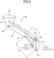
- FIG. 2 is a view illustrating a work apparatus of the wheel loader in FIG. 1 .
- FIG. 3 is a block diagram illustrating a load weighing system for the wheel loader in accordance with example embodiments.
- a wheel loader 10 may include a front body 12 and a rear body 14 connected to each other.
- the front body 12 may include a work apparatus and a front wheel 70.
- the rear body 14 may include a driver cabin 40, an engine bay 50 and a rear wheel 72.
- the work apparatus may include a boom 20 and a bucket 30.
- the boom 20 may be freely pivotally attached to the front body 12, and the bucket 30 may be freely pivotally attached to an end portion of the boom 20.
- the work apparatus may further include other attachments according to customer's working needs.
- the wheel loader including only the bucket 30 attached to the boom 20 as an attachment will be illustrated.
- the boom 20 may be coupled to the front body 12 by a pair of boom cylinders 22.
- a first end portion of the boom cylinder 22 may be freely pivotally attached to the front body 12, and a second end portion of the boom cylinder 22 may be freely pivotally attached to the boom 20.
- the boom 20 may be pivoted upwardly and downwardly by expansion and contraction of the boom cylinders 22.
- the boom 20 may have a first angle (8) with respect to the horizontal plane.
- the horizontal plane may be a plane that is perpendicular to the gradient of the gravity field.
- an angle of a ground surface with respect to the horizontal plane that is, an inclined angle of the ground surface may be a second angle ( ⁇ )
- an angle of the boom 20 with respect to the ground surface may be a third angle ( ⁇ ).
- the first angle (8) may be equal to the sum of the second angle ( ⁇ ) and the third angle ( ⁇ ).
- a tilt arm 34 may be freely rotatably supported on the boom 20, almost at its central portion.
- a first end portion of the tilt arm 34 may be coupled to the front body 12 by a pair of bucket cylinders 32 and a second end portion of the tilt arm 34 may be coupled to the bucket 30 by a tilt rod, so that the bucket 30 may pivot (crowd and dump) as the bucket cylinder 32 expands and contracts.
- FIG. 2 A relationship between the boom 20, the boom cylinder 22 and the bucket 30 may be illustrated in FIG. 2 .
- a boom joint 60 in a first end portion of the boom 20 may be freely pivotally attached to the front body 12, and the bucket 30 may be freely pivotally attached to a bucket joint 66 in a second end portion of the boom 20.
- a boom cylinder joint 62 in the first end portion of the boom cylinder 22 may be freely pivotally attached to the front body 12, and the second end portion of the boom cylinder 22 may be freely pivotally attached to a boom cylinder link mount 64 of the boom 20.
- the boom joint 60 may be spaced apart from the boom cylinder joint 62 in a horizontal direction by a fourth distance (x) and in a vertical direction by a fifth distance (y).
- a distance between the boom joint 60 and the boom cylinder link mount 64 may be a sixth distance (1c)
- a distance between the boom cylinder joint 62 and the boom cylinder link mount 64 may be a seventh distance (1cyl).
- the seventh distance (1cyl) may be a length of the boom cylinder 22.
- a center of gravity of the boom 20 and the bucket 30 may be a first center of gravity (G1), and a center of gravity of a load 80 may be a second center of gravity (G2).
- the second center of gravity (G2) may be positioned in the center of the bucket 30.
- a center of gravity of a system including the boom 20, the bucket 30 and the load 80 may be a third center of gravity (G3).
- distances between the first, second and third centers of gravity (G1, G2, G3) and the boom joint 60 may be a first distance (r1), a second distance (r2) and a third distance (r3), respectively.
- the third distance (r3) may be greater than the first distance (r1) and less than the second distance (r2).
- the boom 20 may pivot about the boom joint 60, so that the bucket 30 and the load 80 may move upwardly.
- the expansion of the cylinder rod may means that the cylinder rod moves and thus the length of the boom cylinder 22 (1cyl, the seventh distance) increases.
- the system including the boom 20, the bucket 30 and the load 80 may pivot in a clockwise direction about the boom joint 60.
- the system including the boom 20, the bucket 30 and the load 80 may be referred to as a pivoting system 200.
- An engine and a travel apparatus for propelling the wheel loader 10 may be mounted at the rear body 14.
- the engine may be provided in the engine bay 50 to supply an output power to the travel apparatus.
- the travel apparatus may include, for example, a torque converter, a transmission, a propeller shaft, axles, etc.
- the front body 12 and the rear body 14 may be rotatably connected to each other through a center pin 16 so that the front body 12 may swing side to side with respect to the rear body 14 by expansion and contraction of a steering cylinder (not illustrated).
- the wheel loader 10 may include a load weighing system 100 for measuring weight of a load.
- the load weighing system 100 may include a detector 110, a coefficient calculator 120, an input portion 130, a calculator 140 and an output portion 150.
- the detector 110 may detect an angle ( ⁇ ) of the boom 20, a pressure (P1, P2) of the boom cylinder 22 and an engine speed of the engine.
- the detected values may be inputted into the coefficient calculator 120 and the calculator 140.
- the detector 110 may include a plurality of sensors.
- the detector 110 may include at least one angle sensor 112 and at least one pressure sensor 114.
- the angle sensor 112 may be installed in the boom joint 60 to measure the angle ( ⁇ ) of the boom 20.
- the angle sensor may be a hall effect sensor.
- the hall effect sensor may be installed in the boom joint 60 as a rotational axis of the boom 20, and may measure the angle ( ⁇ ) of the boom 20 by detecting a change of magnetic flux density according to the pivot of the boom 20.
- the detected angle ( ⁇ ) of the boom 20 may be inputted to the calculator 140.
- the pressure sensor 114 may be installed in the boom cylinder 22 to measure the pressure (PI, P2) of the boom cylinder 22.
- the pressure sensor 114 may include a first pressure sensor 114a installed in a cylinder head side of the boom cylinder 22, and a second pressure sensor 114b installed in a cylinder rod side of the boom cylinder 22.
- the first pressure sensor 114a may detect a pressure P1 of the cylinder head side
- the second pressure sensor 114b may detect a pressure P2 of the cylinder rod side.
- the pressure of the boom cylinder 22 may be a pressure difference between the pressures detected by the first and second pressures sensors 114a and 114b.
- the detected pressure of the boom cylinder 22 may be inputted to the coefficient calculator 120 and the calculator 140.
- the detector 110 may further include an engine speed sensor (not illustrated) for detecting a rotational speed of the engine.
- the engine speed sensor may include a mechanical tachometer, an electrical tachometer, a hall sensor, an optical sensor, etc.
- the detected engine speed may be inputted to the coefficient calculator 120 and the calculator 140.
- the detector may not include the engine speed sensor, and may receive the values of the engine speed from an engine control unit (ECU).
- ECU engine control unit
- the coefficient calculator 120 may determine a damping coefficient and an elastic coefficient of the work apparatus using data and information from the detector 110.
- the coefficient calculator 120 may include a damping coefficient map and an elastic coefficient map obtained through experiments in advance.
- the damping coefficient map may represent relationships between the engine speed, a change rate of the pressure of the boom cylinder 22 and the damping coefficients
- the elastic coefficient map may represent relationships between the engine speed, the change rate of the pressure of the boom cylinder 22 and the elastic coefficients.
- the coefficient calculator 120 may receive the engine speed and the pressure of the boom cylinder 22 from the detector 110 and then may calculate a pressure change rate of the boom cylinder 22 with respect to time.
- the coefficient calculator 120 may extract a damping coefficient and an elastic coefficient from the damping coefficient map and the elastic coefficient map corresponding to the inputted engine speed and pressure change rate of the boom cylinder 22.
- the extracted damping coefficient and elastic coefficient may be inputted to the calculator 140.
- the input portion 130 may receive information of the inclined angle ( ⁇ ) of the ground surface from an operator and may input it to the calculator 140.
- the input portion 130 may include an instrument panel (not illustrated) provided within the driver cabin 40.
- An operator may receive information of the inclined angle ( ⁇ ) of the ground surface in a work area through an angle sensor included in a mobile phone, a map internet application such as Google Maps, etc, and may input directly the information through the instrument panel to the input portion 130, or the input portion 130 may be connected to a telematics system (TMS) to receive a ground surface inclined angle.
- TMS telematics system
- an inclined angle measuring mode may be performed to measure an inclined angle ( ⁇ ) of the ground surface.
- the input portion 130 may be omitted in the load weighing system 100.
- the calculator 140 may use the information inputted from the detector 110 to calculate weight of the load 80.
- the calculator 140 may receive the angle ( ⁇ ) of the boom 20 and the pressure of the boom cylinder 22 from the detector 110, may receive the damping coefficient and the elastic coefficient from the coefficient calculator 120, and may receive the inclined angle ( ⁇ ) of the ground surface from the input portion 130.
- the calculator 140 may calculate the weight of the load 80 using the inputted information.
- steps of measuring the weight of the load 80 performed in the calculator 140 will be explained in detail.
- J is moment of inertia of the pivoting system 200
- c and k are a damping coefficient and a modulus of elasticity of the pivoting system 200
- T represents a torque acting on the pivoting system 200 including the bucket 30 with no load, that is, no load torque
- T L represents a torque acting on the pivoting system 200 including the bucket 30 with load 80, that is, load torque
- ⁇ represents an angle of the boom 20 with respect to the horizontal plane, and accordingly, ⁇ and ⁇ represent an angular speed and an angular acceleration of the boom 20 respectively.
- m 1 is a mass of the boom 20 and the bucket 30, and m 2 is a mass of the load 80.
- r 1 (first distance) is a distance of the first center of gravity (G1) from the boom joint 60
- r 2 (second distance) is a distance of the second center of gravity (G2) from the boom joint 60.
- the no load torque (T) may be expressed using a geometry between the boom 20 and the boom cylinder 22 by following [Equation 3].
- T l c 1 ⁇ x 2 + y 2 ⁇ l cyl 2 ⁇ l c 2 2 l cyl l c 2 F
- F i.e., a force acting on the boom cylinder 22
- F P 1 A 1 ⁇ P 2 A 2
- P 1 is a pressure of the cylinder head side of the boom cylinder 22 detected by the first pressure sensor 114a
- a 1 is an area of the cylinder head side
- P 2 is a pressure of the cylinder rod side of the boom cylinder 22 detected by the second pressure sensor 114b
- a 2 is an area of the cylinder rod side.
- the load torque (T L ) may be expressed using a geometry between the boom 20 and the boom cylinder 22 by following [Equation 5].
- m 3 is a mass of the pivoting system 200 including the boom 20, the bucket 30 and the load 80
- r 3 (third distance) is a distance of the third center of gravity (G3) of the pivoting system 200 from the boom joint 60
- g represents the gravitational acceleration.
- the first angle (8) may be equal to the sum of the second angle ( ⁇ ) and the third angle ( ⁇ ), and thus, accordingly, the angular speed ( ⁇ ) and the angular acceleration ( ⁇ ) of the boom 20 may be expressed by [Equation 8].
- the damping coefficient (c) and the elastic coefficient (k) may be obtained from the coefficient calculator 120.
- the coefficient calculator 120 may receive the engine speed and the pressure information of the boom cylinder 22 from the detector 110.
- the coefficient calculator 120 may perform linear interpolation on the pressures with respect to time to calculate a pressure change rate, and may extract the damping coefficient (c) and the elastic coefficient (k) corresponding to the engine speed and pressure change rate.
- the extracted damping coefficient and elastic coefficient may be inputted to the calculator 140.
- the inclined angle ( ⁇ ) of the ground surface may be obtained from the input portion 130, and the angle ( ⁇ ) of the boom 20 and the pressure (P1, P2) of the boom cylinder 22 may be obtained from the detector 110.
- the calculator 140 may calculate the angular speed ( ⁇ ) and the angular acceleration ( ⁇ ) of the boom 20 from the inputted angle ( ⁇ ) information of the boom 20. For example, the calculator may perform Kalman filtering on the angle ( ⁇ ) of the boom 20 to calculate the angular speed ( ⁇ ) and the angular acceleration ( ⁇ ) of the boom 20.
- the calculator 140 may calculate the weight of the load 80 loaded in the wheel loader 10 while working on the slope.
- the calculator 140 may calculate the inclined angle ( ⁇ ) of the ground surface through the boom 20 raising manipulation. That is, even though the calculator 140 does not receive the inclined angle ( ⁇ ) of the ground surface from the input portion 130, the calculator 140 may calculate directly the inclined angle ( ⁇ ) of the ground surface using information detected by the detector 110 while the boom 20 moves upward.
- the angle ( ⁇ ) of the boom 20 and the pressure (P 1 , P 2 ) of the boom cylinder 22 may be detected by the detector 110, and then, the calculator 140 may use the detected information to calculate the inclined angle ( ⁇ ) of the ground surface.
- steps of calculating the inclined angle ( ⁇ ) of the ground surface performed in the calculator 140 will be explained in detail.
- the calculator 140 may calculate the inclined angle ( ⁇ ) of the ground surface in a work area.
- the load weighing system 100 may further include a comparator (not illustrated) configured to compare the inclined angle of the ground surface inputted from the input portion 130 and the inclined angle of the ground surface calculated by the calculator 140. That is, even though the load weighing system 100 receives the inclined angle of the ground surface from the input portion 130, the load weighing system 100 may calculate directly the inclined angle of the ground surface using the information inputted from the detector 110. Then, as a result of the comparison, when the difference exceeds a predetermined range, the load weighing system 100 may require an operator to input the inclined angle of the ground surface or may recalculate the steps to thereby improve measurement accuracy of the inclined angle ( ⁇ ) of the ground surface. Thus, measurement accuracy of the mass (m 2 ) of the load 80 may be improved.
- a comparator not illustrated
- the mass (m 2 ) of the load 80 calculated by the calculator 140 may be provided to the operator through the output portion 150.
- the output portion may include a visual display device such as an instrument panel, an audio output device such as a speaker, etc.
- the load weighing system 100 may further a selection switch (not illustrated) configured to select one mode of methods of obtaining an inclined angle of the ground surface.
- the selection switch may include an inclined angle input mode and an inclined angle measuring mode. In the inclined angle input mode, an inclined angle of a ground surface may be inputted externally. In the inclined angle measuring mode, an inclined angle of a ground surface may be calculated by itself.
- a driver may input directly the inclined angle of the ground surface through an instrument panel, or the input portion 130 may be connected to a mobile phone or a computing system to receive the inclined angle.
- the angle of the boom 20 and the pressure of the boom cylinder 22 may be detected by the detector 110, and then, the calculator 140 may use the detected information to calculate the inclined angle of the ground surface.
- the load weighing system 100 may measure precisely the weight of the load 80 loaded in the wheel loader 10 while working on the slope. During loading work, the weight of the material loaded into a dump truck may be measured precisely to prevent overloading of the dump truck. Further, overweight loading of the bucket 30 may be prevented to thereby reduce cost of maintaining the wheel loader.
- FIG. 4 is a flowchart illustrating a load weighing method for a wheel loader in accordance with example embodiments.
- FIG. 5 is a flowchart illustrating steps of detecting an inclined angle of a ground surface in FIG. 4 .
- data and information of a wheel loader 10 may be obtained (S100).
- the data and information may include, for example, a mass (m 1 ) of a boom 20 and a bucket 30, a distance (r 1 ) of a center of gravity (G1) of the boom 20 and the bucket 30 from a boom joint 60, a distance (r 2 ) of a center of gravity (G2) of a load 80 from the boom joint 60, a horizontal distance (x) and a vertical distance (y) between the boom joint 60 and a boom cylinder joint 62, a distance (1c) between the boom joint 60 and a boom cylinder link mount 64, and inner areas (A 1 , A 2 ) of the boom cylinder 22.
- the data and information may be inputted in advance and stored in the input portion 130.
- the operator may receive information of the inclined angle ( ⁇ ) of the ground surface in a work area through an angle sensor included in a mobile phone, a map internet application such as Google Maps, etc, and may input directly the inclined angle ( ⁇ ) of the ground surface through the input portion 130.
- a detector 110 and a calculator 130 may be used to obtain the inclined angle of the ground surface, as illustrated in FIG. 5 .
- whether the load 80 is placed on the bucket 30 or not may be determined using a pressure sensor, and then, when the load 80 is placed in the bucket 30, the operator may be notified using a buzzer, a lamp, a display device, etc.
- the angle ( ⁇ ) of the boom 20 with respect to the ground surface may be detected by an angle sensor 112 installed in the boom joint 60, and the inner pressure (P 1 , P 2 ) of the boom cylinder 22 may be detected by a pressure sensor 114. Then, the change in the angle of the boom 20 and the change in the pressure of the boom cylinder 22 with respect to time may be monitored. The detected angle and pressure may be inputted into a calculator 140.
- the calculator 140 may an angular speed ( ⁇ ) and an angular acceleration ( ⁇ ) of the boom 20 using the inputted angle ( ⁇ ) of the boom 20, and may calculate the inclined angle ( ⁇ ) of the ground surface using [Equation 10].
- the load weighing method may further include comparing the inputted inclined angle of the ground surface and the calculated inclined angle of the ground surface.
- an operator may obtain the inclined angle of the ground surface in a work area using an external device such as a mobile phone, and may input the information through the input portion 130. Then, while moving the bucket 30 with no load upwardly, operation state information of the wheel loader 10 may be obtained.
- the inclined angle of the ground surface may be calculated using the calculator 140. Then, the inputted inclined angle of the ground surface and the calculated inclined angle of the ground surface may be compared with each other. When a difference between the inputted inclined angle of the ground surface and the calculated inclined angle of the ground surface exceeds a predetermined range, the operator may be required to input inclined angle information of the ground surface again.
- recalculation may be performed to verify the calculated inclined angle of the ground surface.
- measurement accuracy of the inclined angle ( ⁇ ) of the ground surface may be improved, and further, measurement accuracy of a mass (m 2 ) of the load 80 may be improved.
- the load 80 may be placed on the bucket 30 and the bucket 30 with the load 80 may be pivoted (S120). Then, the change in the angle of the boom 20 and the change in the pressure of the boom cylinder 22 may be detected (S130).
- the angle ( ⁇ ) of the boom 20 with respect to the ground surface may be detected by the angle sensor 112 installed in the boom joint 60, and the inner pressure (P 1 , P 2 ) of the boom cylinder 22 may be detected by the pressure sensor 114 installed in the boom cylinder 22. Then, the change in the angle of the boom 20 and the change in the pressure of the boom cylinder 22 with respect to time may be monitored. Additionally, information of an engine speed may be obtained using an engine speed sensor. The obtained information may be inputted into a coefficient calculator 120 and the calculator 140.
- the coefficient calculator 120 may determine a damping coefficient (c) and an elastic coefficient (k) using the inputted engine speed and change in the pressure of the boom cylinder 22.
- the calculated damping coefficient (c) and elastic coefficient (k) may be inputted to the calculator 140.
- the calculator 140 may calculate the angular speed ( ⁇ ) and the angular acceleration ( ⁇ ) of the boom 20 from the inputted angle ( ⁇ ) of the boom 20, and may and may calculate weight of the mass (m 2 ) of the load 80 using [Equation 9].
- the weight of the mass (m 2 ) of the load 80 may be provided to the operator through an output portion 150 (S150).
- the weight of the mass (m 2 ) of the load 80 may be displayed with letters or numbers in the instrument panel, or may be notified to the operator by a speaker. Alternatively, only when the mass (m 2 ) of the load 80 exceeds the maximum loading capacity of the bucket 30, a warning message may be displayed.
- the weight of the load 80 loaded in the wheel loader 10 while working on the slope may be precisely measured.
- the weight of the material loaded into a dump truck may be measured precisely to prevent overloading of the dump truck. Further, overweight loading of the bucket 30 may be prevented to thereby reduce cost of maintaining the wheel loader 10.
Landscapes
- Engineering & Computer Science (AREA)
- Physics & Mathematics (AREA)
- General Physics & Mathematics (AREA)
- Mining & Mineral Resources (AREA)
- Civil Engineering (AREA)
- General Engineering & Computer Science (AREA)
- Structural Engineering (AREA)
- Radar, Positioning & Navigation (AREA)
- Remote Sensing (AREA)
- Component Parts Of Construction Machinery (AREA)
- Mechanical Engineering (AREA)
- Operation Control Of Excavators (AREA)
Abstract
Description
- Example embodiments relate to a load weighing method and system for a wheel loader. More particularly, Example embodiments relate to a method of measuring weight of a load in the wheel loader and a load weighing system for performing the same.
- In general, an industrial vehicle such as a wheel loader is widely used to excavate sand, gravel, and the like and load it into a dump truck.
- A loading charge for the dump truck may be estimated depending on an amount of a material loaded into the dump truck, and when an industrial vehicle travels in a state that weight of a load exceeds the maximum loading capacity for the dump truck, a penalty may be imposed. Further, overweight bucket loading may cause damages to the wheel loader. Accordingly, in order to prevent overloading of the dump truck and reduce cost of maintaining the wheel loader, it may be required to accurately measure weight of loads.
- Example embodiments provide a method of measuring weight of a load in a wheel loader working on a slope.
- Example embodiments provide a system for measuring weight of a load in a wheel loader working on a slope.
- According to example embodiments, in a load weighing method for a wheel loader, a change in a boom angle and a change in a pressure of a boom cylinder are detected while pivoting the boom and an attachment connected to the boom, wherein a load is placed on the attachment. Weight of the load is calculated by using an inclined angle of a ground surface, the change in the boom angle and the change in the pressure of the boom cylinder as variables of a rotational dynamic equation for the pivot of the boom.
- In example embodiments, the method may further include detecting the inclined angle of the ground surface on a slope where the wheel loader is working.
- In example embodiments, detecting the inclined angle of the ground surface may include receiving the inclined angle of the ground surface from at least one of an angle sensor included in a mobile phone and a map internet application.
- In example embodiments, detecting the inclined angle of the ground surface may include detecting a change in the boom angle and a change in the pressure of the boom cylinder while pivoting the boom, wherein no load is placed on the attachment, and calculating the inclined angle of the ground surface using the change in the boom angle and the change in the pressure of the boom cylinder from the rotational dynamic equation for the pivot of the boom.
- In example embodiments, detecting the inclined angle of the ground surface may further include receiving the inclined angle of the ground surface from at least one of an angle sensor included in a mobile phone and a map internet application, and when a difference between the received inclined angle of the ground surface and the calculated inclined angle of the ground surface exceeds a predetermined range, operating at least one of receiving the inclined angle of the ground surface and calculating the inclined angle of the ground surface again.
- In example embodiments, calculating the weight of the load may include extracting a damping coefficient and an elastic coefficient from a predetermined damping coefficient map and elastic coefficient map corresponding to the change in the pressure of the boom cylinder.
- In example embodiments, the rotational dynamic equation may be an equation representing a difference between no load torque and load torque prediction and derived by geometric relationships between the boom, the boom cylinder and the attachment.
- In example embodiments, the method may further include outputting the calculated weight of the load.
- According to example embodiments, a load weighing system for a wheel loader includes a detector including an angle sensor installed in a boom of the wheel loader to detect a change in an angle of the boom and a pressure sensor installed in a boom cylinder to detect a change in a pressure of the boom cylinder, and a calculator configured to calculate an inclined angle of a ground surface or weight of a load placed on an attachment connected to the boom using the change in the boom angle and the change in the pressure of the boom cylinder from a rotational dynamic equation for the pivot of the boom.
- In example embodiments, the calculator may be adapted to calculate the inclined angle of the ground surface when no load is placed on the attachment, and the calculator may be adapted to calculate the weight of the load when the load is placed on the attachment.
- In example embodiments, the load weighing system may further include an input portion configured to receive the inclined angle of the ground surface from at least one of an angle sensor included in a mobile phone and a map internet application.
- In example embodiments, the load weighing system may further include a coefficient calculator including a damping coefficient map and an elastic coefficient map, a damping coefficient and an elastic coefficient corresponding to the change in the pressure of the boom cylinder being stored respectively in the damping coefficient map and the elastic coefficient map.
- In example embodiments, the load weighing system may further include an output portion configured to provide a drive with the weight information of the load calculated by the calculator.
- According to example embodiments, weight of a load in a wheel loader while working on a slope may be precisely measured. During loading work of the wheel loader, overloading of the dump truck may be prevented and overweight loading of a bucket may be prevented to thereby reduce cost of maintaining the wheel loader.
- Example embodiments will be more clearly understood from the following detailed description taken in conjunction with the accompanying drawings.
FIGS. 1 to 5 represent non-limiting, example embodiments as described herein. -
FIG. 1 is a side view illustrating a wheel loader in accordance with example embodiments. -
FIG. 2 is a view illustrating a work apparatus of the wheel loader inFIG. 1 . -
FIG. 3 is a block diagram illustrating a load weighing system for the wheel loader in accordance with example embodiments. -
FIG. 4 is a flowchart illustrating a load weighing method for a wheel loader in accordance with example embodiments. -
FIG. 5 is a flowchart illustrating steps of detecting an inclined angle of a ground surface inFIG. 4 . - Various example embodiments will be described more fully hereinafter with reference to the accompanying drawings, in which some example embodiments are shown. The present inventive concept may, however, be embodied in many different forms and should not be construed as limited to the example embodiments set forth herein. Rather, these example embodiments are provided so that this description will be thorough and complete, and will fully convey the scope of the present inventive concept to those skilled in the art. In the drawings, the sizes and relative sizes of layers and regions may be exaggerated for clarity.
- It will be understood that when an element or layer is referred to as being "on," "connected to" or "coupled to" another element or layer, it can be directly on, connected or coupled to the other element or layer or intervening elements or layers may be present. In contrast, when an element is referred to as being "directly on," "directly connected to" or "directly coupled to" another element or layer, there are no intervening elements or layers present. Like numerals refer to like elements throughout. As used herein, the term "and/or" includes any and all combinations of one or more of the associated listed items.
- It will be understood that, although the terms first, second, third, fourth etc. may be used herein to describe various elements, components, regions, layers and/or sections, these elements, components, regions, layers and/or sections should not be limited by these terms. These terms are only used to distinguish one element, component, region, layer or section from another region, layer or section. Thus, a first element, component, region, layer or section discussed below could be termed a second element, component, region, layer or section without departing from the teachings of the present inventive concept.
- The terminology used herein is for the purpose of describing particular example embodiments only and is not intended to be limiting of the present inventive concept. As used herein, the singular forms "a," "an" and "the" are intended to include the plural forms as well, unless the context clearly indicates otherwise. It will be further understood that the terms "comprises" and/or "comprising," when used in this specification, specify the presence of stated features, integers, steps, operations, elements, and/or components, but do not preclude the presence or addition of one or more other features, integers, steps, operations, elements, components, and/or groups thereof.
- Unless otherwise defined, all terms (including technical and scientific terms) used herein have the same meaning as commonly understood by one of ordinary skill in the art to which this inventive concept belongs. It will be further understood that terms, such as those defined in commonly used dictionaries, should be interpreted as having a meaning that is consistent with their meaning in the context of the relevant art and will not be interpreted in an idealized or overly formal sense unless expressly so defined herein.
-
FIG. 1 is a side view illustrating a wheel loader in accordance with example embodiments.FIG. 2 is a view illustrating a work apparatus of the wheel loader inFIG. 1 .FIG. 3 is a block diagram illustrating a load weighing system for the wheel loader in accordance with example embodiments. - Referring to
FIGS. 1 to 3 , awheel loader 10 may include afront body 12 and arear body 14 connected to each other. Thefront body 12 may include a work apparatus and afront wheel 70. Therear body 14 may include adriver cabin 40, anengine bay 50 and arear wheel 72. - The work apparatus may include a
boom 20 and abucket 30. Theboom 20 may be freely pivotally attached to thefront body 12, and thebucket 30 may be freely pivotally attached to an end portion of theboom 20. Here, the work apparatus may further include other attachments according to customer's working needs. Hereinafter, for the convenience of explanation, the wheel loader including only thebucket 30 attached to theboom 20 as an attachment will be illustrated. - The
boom 20 may be coupled to thefront body 12 by a pair ofboom cylinders 22. A first end portion of theboom cylinder 22 may be freely pivotally attached to thefront body 12, and a second end portion of theboom cylinder 22 may be freely pivotally attached to theboom 20. Theboom 20 may be pivoted upwardly and downwardly by expansion and contraction of theboom cylinders 22. - As the
boom 20 rotates, theboom 20 may have a first angle (8) with respect to the horizontal plane. The horizontal plane may be a plane that is perpendicular to the gradient of the gravity field. On the other hand, when thewheel loader 20 is operating on a slope, an angle of a ground surface with respect to the horizontal plane, that is, an inclined angle of the ground surface may be a second angle (α), and an angle of theboom 20 with respect to the ground surface may be a third angle (β). The first angle (8) may be equal to the sum of the second angle (α) and the third angle (β). - A
tilt arm 34 may be freely rotatably supported on theboom 20, almost at its central portion. A first end portion of thetilt arm 34 may be coupled to thefront body 12 by a pair ofbucket cylinders 32 and a second end portion of thetilt arm 34 may be coupled to thebucket 30 by a tilt rod, so that thebucket 30 may pivot (crowd and dump) as thebucket cylinder 32 expands and contracts. - A relationship between the
boom 20, theboom cylinder 22 and thebucket 30 may be illustrated inFIG. 2 . As illustrated inFIG. 2 , a boom joint 60 in a first end portion of theboom 20 may be freely pivotally attached to thefront body 12, and thebucket 30 may be freely pivotally attached to a bucket joint 66 in a second end portion of theboom 20. A boom cylinder joint 62 in the first end portion of theboom cylinder 22 may be freely pivotally attached to thefront body 12, and the second end portion of theboom cylinder 22 may be freely pivotally attached to a boomcylinder link mount 64 of theboom 20. - In this case, the boom joint 60 may be spaced apart from the boom cylinder joint 62 in a horizontal direction by a fourth distance (x) and in a vertical direction by a fifth distance (y). A distance between the boom joint 60 and the boom
cylinder link mount 64 may be a sixth distance (1c), and a distance between the boom cylinder joint 62 and the boomcylinder link mount 64 may be a seventh distance (1cyl). The seventh distance (1cyl) may be a length of theboom cylinder 22. - A center of gravity of the
boom 20 and thebucket 30 may be a first center of gravity (G1), and a center of gravity of aload 80 may be a second center of gravity (G2). For example, the second center of gravity (G2) may be positioned in the center of thebucket 30. A center of gravity of a system including theboom 20, thebucket 30 and theload 80 may be a third center of gravity (G3). In this case, distances between the first, second and third centers of gravity (G1, G2, G3) and the boom joint 60 may be a first distance (r1), a second distance (r2) and a third distance (r3), respectively. For example, the third distance (r3) may be greater than the first distance (r1) and less than the second distance (r2). - As a cylinder rod of the
boom cylinder 22 expands, theboom 20 may pivot about the boom joint 60, so that thebucket 30 and theload 80 may move upwardly. Here, the expansion of the cylinder rod may means that the cylinder rod moves and thus the length of the boom cylinder 22 (1cyl, the seventh distance) increases. As the length of the boom cylinder 22 (1cyl, the seventh distance) increases, the system including theboom 20, thebucket 30 and theload 80 may pivot in a clockwise direction about theboom joint 60. Hereinafter, for the convenience of explanation, the system including theboom 20, thebucket 30 and theload 80 may be referred to as apivoting system 200. - An engine and a travel apparatus for propelling the
wheel loader 10 may be mounted at therear body 14. The engine may be provided in theengine bay 50 to supply an output power to the travel apparatus. The travel apparatus may include, for example, a torque converter, a transmission, a propeller shaft, axles, etc. - The
front body 12 and therear body 14 may be rotatably connected to each other through acenter pin 16 so that thefront body 12 may swing side to side with respect to therear body 14 by expansion and contraction of a steering cylinder (not illustrated). - In example embodiments, the
wheel loader 10 may include aload weighing system 100 for measuring weight of a load. As illustrated inFIG. 3 , theload weighing system 100 may include adetector 110, acoefficient calculator 120, aninput portion 130, acalculator 140 and anoutput portion 150. - The
detector 110 may detect an angle (β) of theboom 20, a pressure (P1, P2) of theboom cylinder 22 and an engine speed of the engine. The detected values may be inputted into thecoefficient calculator 120 and thecalculator 140. - In example embodiments, the
detector 110 may include a plurality of sensors. For example, thedetector 110 may include at least oneangle sensor 112 and at least onepressure sensor 114. - The
angle sensor 112 may be installed in the boom joint 60 to measure the angle (β) of theboom 20. For example, the angle sensor may be a hall effect sensor. The hall effect sensor may be installed in the boom joint 60 as a rotational axis of theboom 20, and may measure the angle (β) of theboom 20 by detecting a change of magnetic flux density according to the pivot of theboom 20. The detected angle (β) of theboom 20 may be inputted to thecalculator 140. - The
pressure sensor 114 may be installed in theboom cylinder 22 to measure the pressure (PI, P2) of theboom cylinder 22. For example, thepressure sensor 114 may include afirst pressure sensor 114a installed in a cylinder head side of theboom cylinder 22, and asecond pressure sensor 114b installed in a cylinder rod side of theboom cylinder 22. Thefirst pressure sensor 114a may detect a pressure P1 of the cylinder head side, and thesecond pressure sensor 114b may detect a pressure P2 of the cylinder rod side. The pressure of theboom cylinder 22 may be a pressure difference between the pressures detected by the first andsecond pressures sensors boom cylinder 22 may be inputted to thecoefficient calculator 120 and thecalculator 140. - In example embodiments, the
detector 110 may further include an engine speed sensor (not illustrated) for detecting a rotational speed of the engine. The engine speed sensor may include a mechanical tachometer, an electrical tachometer, a hall sensor, an optical sensor, etc. The detected engine speed may be inputted to thecoefficient calculator 120 and thecalculator 140. Alternatively, the detector may not include the engine speed sensor, and may receive the values of the engine speed from an engine control unit (ECU). - The
coefficient calculator 120 may determine a damping coefficient and an elastic coefficient of the work apparatus using data and information from thedetector 110. - In example embodiments, the
coefficient calculator 120 may include a damping coefficient map and an elastic coefficient map obtained through experiments in advance. The damping coefficient map may represent relationships between the engine speed, a change rate of the pressure of theboom cylinder 22 and the damping coefficients, and the elastic coefficient map may represent relationships between the engine speed, the change rate of the pressure of theboom cylinder 22 and the elastic coefficients. Thecoefficient calculator 120 may receive the engine speed and the pressure of theboom cylinder 22 from thedetector 110 and then may calculate a pressure change rate of theboom cylinder 22 with respect to time. Thecoefficient calculator 120 may extract a damping coefficient and an elastic coefficient from the damping coefficient map and the elastic coefficient map corresponding to the inputted engine speed and pressure change rate of theboom cylinder 22. The extracted damping coefficient and elastic coefficient may be inputted to thecalculator 140. - The
input portion 130 may receive information of the inclined angle (α) of the ground surface from an operator and may input it to thecalculator 140. For example, theinput portion 130 may include an instrument panel (not illustrated) provided within thedriver cabin 40. An operator may receive information of the inclined angle (α) of the ground surface in a work area through an angle sensor included in a mobile phone, a map internet application such as Google Maps, etc, and may input directly the information through the instrument panel to theinput portion 130, or theinput portion 130 may be connected to a telematics system (TMS) to receive a ground surface inclined angle. Alternatively, as described later, an inclined angle measuring mode may be performed to measure an inclined angle (α) of the ground surface. In this case, theinput portion 130 may be omitted in theload weighing system 100. - The
calculator 140 may use the information inputted from thedetector 110 to calculate weight of theload 80. In particular, thecalculator 140 may receive the angle (β) of theboom 20 and the pressure of theboom cylinder 22 from thedetector 110, may receive the damping coefficient and the elastic coefficient from thecoefficient calculator 120, and may receive the inclined angle (α) of the ground surface from theinput portion 130. Thecalculator 140 may calculate the weight of theload 80 using the inputted information. Hereinafter, steps of measuring the weight of theload 80 performed in thecalculator 140 will be explained in detail. - Referring again to
FIG. 2 , as the cylinder rod of theboom cylinder 22 expands, thepivoting system 200 including theboom 20, thebucket 30 and theload 80 may pivot in a clockwise direction. Here, a rotational dynamic equation of thepivoting system 200 may be expressed by following [Equation 1]
- Here, J is moment of inertia of the
pivoting system 200, and c and k are a damping coefficient and a modulus of elasticity of thepivoting system 200. T represents a torque acting on thepivoting system 200 including thebucket 30 with no load, that is, no load torque, and TL represents a torque acting on thepivoting system 200 including thebucket 30 withload 80, that is, load torque. Additionally, θ represents an angle of theboom 20 with respect to the horizontal plane, and accordingly, θ̇ and θ̈ represent an angular speed and an angular acceleration of theboom 20 respectively. - The moment of inertia (J) of the
pivoting system 200 may be calculated by following [Equation 2].
- Here, m1 is a mass of the
boom 20 and thebucket 30, and m2 is a mass of theload 80. r1 (first distance) is a distance of the first center of gravity (G1) from the boom joint 60, and r2 (second distance) is a distance of the second center of gravity (G2) from theboom joint 60. - The no load torque (T) may be expressed using a geometry between the
boom 20 and theboom cylinder 22 by following [Equation 3].
- Here, F, i.e., a force acting on the
boom cylinder 22, may be calculated using inner pressures of theboom cylinder 22 detected by the first andsecond pressure sensors 
- Here, P1 is a pressure of the cylinder head side of the
boom cylinder 22 detected by thefirst pressure sensor 114a, and A1 is an area of the cylinder head side. P2 is a pressure of the cylinder rod side of theboom cylinder 22 detected by thesecond pressure sensor 114b, and A2 is an area of the cylinder rod side. - The load torque (TL) may be expressed using a geometry between the
boom 20 and theboom cylinder 22 by following [Equation 5].
- Here, m3 is a mass of the
pivoting system 200 including theboom 20, thebucket 30 and theload 80, r3 (third distance) is a distance of the third center of gravity (G3) of thepivoting system 200 from the boom joint 60, and g represents the gravitational acceleration. - The third distance (r3) and the first and second distances (r1, r2) may satisfy following [Equation 6].

- By substituting [Equation 6] into [Equation 5], the load torque (TL) may be expressed by [Equation 7].

- On the other hand, the first angle (8) may be equal to the sum of the second angle (α) and the third angle (β), and thus, accordingly, the angular speed (θ̇) and the angular acceleration (θ̈) of the
boom 20 may be expressed by [Equation 8].
- By substituting [Equation 2], [Equation 3], [Equation 4], [Equation 7] and [Equation 8] into [Equation 1], the mass (m2) of the
load 80 may be expressed by [Equation 9].
- The damping coefficient (c) and the elastic coefficient (k) may be obtained from the
coefficient calculator 120. Thecoefficient calculator 120 may receive the engine speed and the pressure information of theboom cylinder 22 from thedetector 110. Thecoefficient calculator 120 may perform linear interpolation on the pressures with respect to time to calculate a pressure change rate, and may extract the damping coefficient (c) and the elastic coefficient (k) corresponding to the engine speed and pressure change rate. The extracted damping coefficient and elastic coefficient may be inputted to thecalculator 140. - The inclined angle (α) of the ground surface may be obtained from the
input portion 130, and the angle (β) of theboom 20 and the pressure (P1, P2) of theboom cylinder 22 may be obtained from thedetector 110. - The
calculator 140 may calculate the angular speed (β̇) and the angular acceleration (β̈) of theboom 20 from the inputted angle (β) information of theboom 20. For example, the calculator may perform Kalman filtering on the angle (β) of theboom 20 to calculate the angular speed (β̇) and the angular acceleration (β̈) of theboom 20. - By putting the known values (1c, 1cyl, x, y, A1, A2, m1, r1, r2, g), the values (P1, P2, β) inputted from the
detector 110, the values (c, k) inputted from thecoefficient calculator 120 and the values (β̇, β̈) calculated by thecalculator 140 in [Equation 9], thecalculator 140 may calculate the weight of theload 80 loaded in thewheel loader 10 while working on the slope. - In example embodiments, the
calculator 140 may calculate the inclined angle (α) of the ground surface through theboom 20 raising manipulation. That is, even though thecalculator 140 does not receive the inclined angle (α) of the ground surface from theinput portion 130, thecalculator 140 may calculate directly the inclined angle (α) of the ground surface using information detected by thedetector 110 while theboom 20 moves upward. - For example, while the
bucket 30 with no load moves upward, the angle (β) of theboom 20 and the pressure (P1, P2) of theboom cylinder 22 may be detected by thedetector 110, and then, thecalculator 140 may use the detected information to calculate the inclined angle (α) of the ground surface. Hereinafter, steps of calculating the inclined angle (α) of the ground surface performed in thecalculator 140 will be explained in detail. - Because the
load 80 is not loaded in thebucket 30, the mass (m2) of theload 80 in [Equation 9] may be substituted with zero. Then, [Equation 9] may be rewritten for the inclined angle (α) of the ground surface. In here, following two assumptions may be used for linearization and simplification of equation.

- Thus, following [Equation 10] maybe obtained.

- By putting the known values (1c, 1cyl, x, y, A1, A2, m1, r1, r2, g), the values (P1, P2, β) inputted from the
detector 110, the value (c) inputted from thecoefficient calculator 120 and the values (β̇,β̈+) calculated by thecalculator 140 in [Equation 10], thecalculator 140 may calculate the inclined angle (α) of the ground surface in a work area. - In example embodiments, the
load weighing system 100 may further include a comparator (not illustrated) configured to compare the inclined angle of the ground surface inputted from theinput portion 130 and the inclined angle of the ground surface calculated by thecalculator 140. That is, even though theload weighing system 100 receives the inclined angle of the ground surface from theinput portion 130, theload weighing system 100 may calculate directly the inclined angle of the ground surface using the information inputted from thedetector 110. Then, as a result of the comparison, when the difference exceeds a predetermined range, theload weighing system 100 may require an operator to input the inclined angle of the ground surface or may recalculate the steps to thereby improve measurement accuracy of the inclined angle (α) of the ground surface. Thus, measurement accuracy of the mass (m2) of theload 80 may be improved. - The mass (m2) of the
load 80 calculated by thecalculator 140 may be provided to the operator through theoutput portion 150. For example, the output portion may include a visual display device such as an instrument panel, an audio output device such as a speaker, etc. - In example embodiments, the
load weighing system 100 may further a selection switch (not illustrated) configured to select one mode of methods of obtaining an inclined angle of the ground surface. For example, the selection switch may include an inclined angle input mode and an inclined angle measuring mode. In the inclined angle input mode, an inclined angle of a ground surface may be inputted externally. In the inclined angle measuring mode, an inclined angle of a ground surface may be calculated by itself. - When the inclined angle input mode is selected, a driver may input directly the inclined angle of the ground surface through an instrument panel, or the
input portion 130 may be connected to a mobile phone or a computing system to receive the inclined angle. - When the inclined angle input mode is selected, while the
bucket 30 with no load moves upward, the angle of theboom 20 and the pressure of theboom cylinder 22 may be detected by thedetector 110, and then, thecalculator 140 may use the detected information to calculate the inclined angle of the ground surface. - As mentioned above, the
load weighing system 100 may measure precisely the weight of theload 80 loaded in thewheel loader 10 while working on the slope. During loading work, the weight of the material loaded into a dump truck may be measured precisely to prevent overloading of the dump truck. Further, overweight loading of thebucket 30 may be prevented to thereby reduce cost of maintaining the wheel loader. - Hereinafter, a method of measuring weight of a
load 80 on thewheel loader 10 using theload weighing system 100 inFIG. 3 will be explained. -
FIG. 4 is a flowchart illustrating a load weighing method for a wheel loader in accordance with example embodiments.FIG. 5 is a flowchart illustrating steps of detecting an inclined angle of a ground surface inFIG. 4 . - Referring to
FIG. 4 , data and information of awheel loader 10 may be obtained (S100). - An operator may input data and information of the
wheel loader 10 through aninput portion 130. As illustrated inFIG. 2 , the data and information may include, for example, a mass (m1) of aboom 20 and abucket 30, a distance (r1) of a center of gravity (G1) of theboom 20 and thebucket 30 from a boom joint 60, a distance (r2) of a center of gravity (G2) of aload 80 from the boom joint 60, a horizontal distance (x) and a vertical distance (y) between the boom joint 60 and a boom cylinder joint 62, a distance (1c) between the boom joint 60 and a boomcylinder link mount 64, and inner areas (A1, A2) of theboom cylinder 22. Alternatively, the data and information may be inputted in advance and stored in theinput portion 130. - The, an inclined angle of a ground surface maybe obtained (S110).
- For example, the operator may receive information of the inclined angle (α) of the ground surface in a work area through an angle sensor included in a mobile phone, a map internet application such as Google Maps, etc, and may input directly the inclined angle (α) of the ground surface through the
input portion 130. - Alternatively, without using an external device such as the mobile phone, a
detector 110 and acalculator 130 may be used to obtain the inclined angle of the ground surface, as illustrated inFIG. 5 . - Referring to
Fig. 5 , first, whether thebucket 30 is empty or not may be checked (S200), and then, when theload 80 is loaded in thebucket 30, a warning message may be outputted (S210). - For example, whether the
load 80 is placed on thebucket 30 or not may be determined using a pressure sensor, and then, when theload 80 is placed in thebucket 30, the operator may be notified using a buzzer, a lamp, a display device, etc. - When no load is placed in the
bucket 30, while the boom pivots (S220), a change in the angle of theboom 20 and a change in a pressure of theboom cylinder 22 may be detected (S230). - For example, the angle (β) of the
boom 20 with respect to the ground surface may be detected by anangle sensor 112 installed in the boom joint 60, and the inner pressure (P1, P2) of theboom cylinder 22 may be detected by apressure sensor 114. Then, the change in the angle of theboom 20 and the change in the pressure of theboom cylinder 22 with respect to time may be monitored. The detected angle and pressure may be inputted into acalculator 140. - The
calculator 140 may an angular speed (β̇) and an angular acceleration (β̈) of theboom 20 using the inputted angle (β) of theboom 20, and may calculate the inclined angle (α) of the ground surface using [Equation 10]. - In example embodiments, the load weighing method may further include comparing the inputted inclined angle of the ground surface and the calculated inclined angle of the ground surface.
- In particular, an operator may obtain the inclined angle of the ground surface in a work area using an external device such as a mobile phone, and may input the information through the
input portion 130. Then, while moving thebucket 30 with no load upwardly, operation state information of thewheel loader 10 may be obtained. The inclined angle of the ground surface may be calculated using thecalculator 140. Then, the inputted inclined angle of the ground surface and the calculated inclined angle of the ground surface may be compared with each other. When a difference between the inputted inclined angle of the ground surface and the calculated inclined angle of the ground surface exceeds a predetermined range, the operator may be required to input inclined angle information of the ground surface again. Alternatively, assuming that the inputted inclined angle of the ground surface is correct, recalculation may be performed to verify the calculated inclined angle of the ground surface. Thus, measurement accuracy of the inclined angle (α) of the ground surface may be improved, and further, measurement accuracy of a mass (m2) of theload 80 may be improved. - After obtaining the inclined angle information of the ground surface, the
load 80 may be placed on thebucket 30 and thebucket 30 with theload 80 may be pivoted (S120). Then, the change in the angle of theboom 20 and the change in the pressure of theboom cylinder 22 may be detected (S130). - For example, the angle (β) of the
boom 20 with respect to the ground surface may be detected by theangle sensor 112 installed in the boom joint 60, and the inner pressure (P1, P2) of theboom cylinder 22 may be detected by thepressure sensor 114 installed in theboom cylinder 22. Then, the change in the angle of theboom 20 and the change in the pressure of theboom cylinder 22 with respect to time may be monitored. Additionally, information of an engine speed may be obtained using an engine speed sensor. The obtained information may be inputted into acoefficient calculator 120 and thecalculator 140. - The
coefficient calculator 120 may determine a damping coefficient (c) and an elastic coefficient (k) using the inputted engine speed and change in the pressure of theboom cylinder 22. The calculated damping coefficient (c) and elastic coefficient (k) may be inputted to thecalculator 140. - The
calculator 140 may calculate the angular speed (β̇) and the angular acceleration (β̈) of theboom 20 from the inputted angle (β) of theboom 20, and may and may calculate weight of the mass (m2) of theload 80 using [Equation 9]. - The weight of the mass (m2) of the
load 80 may be provided to the operator through an output portion 150 (S150). - For example, the weight of the mass (m2) of the
load 80 may be displayed with letters or numbers in the instrument panel, or may be notified to the operator by a speaker. Alternatively, only when the mass (m2) of theload 80 exceeds the maximum loading capacity of thebucket 30, a warning message may be displayed. - As mentioned above, according to the load weighing method, the weight of the
load 80 loaded in thewheel loader 10 while working on the slope may be precisely measured. During loading work of the wheel loader, the weight of the material loaded into a dump truck may be measured precisely to prevent overloading of the dump truck. Further, overweight loading of thebucket 30 may be prevented to thereby reduce cost of maintaining thewheel loader 10. - The foregoing is illustrative of example embodiments of the invention and is not to be construed as limiting thereof. Although a few example embodiments have been described, those skilled in the art will readily appreciate that many modifications are possible in the example embodiments without materially departing from the novel teachings and advantages of the present inventive concept. Accordingly, all such modifications are intended to be included within the scope of the present inventive concept as defined in the claims. Therefore, it is to be understood that the foregoing is illustrative of various example embodiments and is not to be construed as limited to the specific example embodiments disclosed, and that modifications to the disclosed example embodiments, as well as other example embodiments, are intended to be included within the scope of the appended claims.
Claims (13)
- A load weighing method for a wheel loader, comprising:detecting a change in a boom angle and a change in a pressure of a boom cylinder while pivoting the boom and an attachment connected to the boom, wherein a load is placed on the attachment; andcalculating weight of the load by using an inclined angle of a ground surface, the change in the boom angle and the change in the pressure of the boom cylinder as variables of a rotational dynamic equation for the pivot of the boom.
- The method of claim 1, further comprising detecting the inclined angle of the ground surface on a slope where the wheel loader is working.
- The method of claim 2, wherein detecting the inclined angle of the ground surface comprises receiving the inclined angle of the ground surface from at least one of an angle sensor included in a mobile phone and a map internet application.
- The method of claim 2, wherein detecting the inclined angle of the ground surface comprises:detecting a change in the boom angle and a change in the pressure of the boom cylinder while pivoting the boom, wherein no load is placed on the attachment; andcalculating the inclined angle of the ground surface using the change in the boom angle and the change in the pressure of the boom cylinder from the rotational dynamic equation for the pivot of the boom.
- The method of claim 4, wherein detecting the inclined angle of the ground surface further comprises:receiving the inclined angle of the ground surface from at least one of an angle sensor included in a mobile phone and a map internet application; andwhen a difference between the received inclined angle of the ground surface and the calculated inclined angle of the ground surface exceeds a predetermined range, operating at least one of receiving the inclined angle of the ground surface and calculating the inclined angle of the ground surface again.
- The method of claim 1, wherein calculating the weight of the load comprises extracting a damping coefficient and an elastic coefficient from a predetermined damping coefficient map and elastic coefficient map corresponding to the change in the pressure of the boom cylinder.
- The method of claim 1, wherein the rotational dynamic equation is an equation representing a difference between no load torque and load torque prediction and derived by geometric relationships between the boom, the boom cylinder and the attachment.
- The method of claim 1, further comprising outputting the calculated weight of the load.
- A load weighing system for a wheel loader, comprising:a detector including an angle sensor installed in a boom of the wheel loader to detect a change in an angle of the boom and a pressure sensor installed in a boom cylinder to detect a change in a pressure of the boom cylinder; anda calculator configured to calculate an inclined angle of a ground surface or weight of a load placed on an attachment connected to the boom using the change in the boom angle and the change in the pressure of the boom cylinder from a rotational dynamic equation for the pivot of the boom.
- The load weighing system of claim 9, wherein the calculator is adapted to calculate the inclined angle of the ground surface when no load is placed on the attachment, and the calculator is adapted to calculate the weight of the load when the load is placed on the attachment.
- The load weighing system of claim 9, further comprising an input portion configured to receive the inclined angle of the ground surface from at least one of an angle sensor included in a mobile phone and a map internet application.
- The load weighing system of claim 9, further comprising a coefficient calculator including a damping coefficient map and an elastic coefficient map, a damping coefficient and an elastic coefficient corresponding to the change in the pressure of the boom cylinder being stored respectively in the damping coefficient map and the elastic coefficient map.
- The load weighing system of claim 9, further comprising an output portion configured to provide a drive with the weight information of the load calculated by the calculator.
Applications Claiming Priority (1)
| Application Number | Priority Date | Filing Date | Title |
|---|---|---|---|
| KR1020150156425A KR102479557B1 (en) | 2015-11-09 | 2015-11-09 | Load weighing method and system for wheel loader |
Publications (2)
| Publication Number | Publication Date |
|---|---|
| EP3165885A1 true EP3165885A1 (en) | 2017-05-10 |
| EP3165885B1 EP3165885B1 (en) | 2020-09-02 |
Family
ID=57281098
Family Applications (1)
| Application Number | Title | Priority Date | Filing Date |
|---|---|---|---|
| EP16197963.8A Active EP3165885B1 (en) | 2015-11-09 | 2016-11-09 | Load weighing method and system for wheel loader |
Country Status (4)
| Country | Link |
|---|---|
| US (1) | US10539451B2 (en) |
| EP (1) | EP3165885B1 (en) |
| KR (1) | KR102479557B1 (en) |
| CN (1) | CN106836366B (en) |
Cited By (2)
| Publication number | Priority date | Publication date | Assignee | Title |
|---|---|---|---|---|
| EP4148193A1 (en) * | 2021-09-14 | 2023-03-15 | Robert Bosch GmbH | Method for invoking a weighing function of a working machine and working machine |
| US11945705B2 (en) | 2018-09-13 | 2024-04-02 | Crown Equipment Corporation | System and method for controlling a maximum vehicle speed for an industrial vehicle based on a calculated load |
Families Citing this family (26)
| Publication number | Priority date | Publication date | Assignee | Title |
|---|---|---|---|---|
| JP6749878B2 (en) * | 2017-09-29 | 2020-09-02 | 日立建機株式会社 | Wheel loader and bucket load calculation method |
| JP2019066306A (en) * | 2017-09-29 | 2019-04-25 | 株式会社Kcm | Wheel loader |
| CN107884045B (en) * | 2017-10-25 | 2019-09-10 | 厦门大学 | A kind of wheel loader load-carrying measuring method based on vibration |
| JP6971888B2 (en) * | 2018-03-05 | 2021-11-24 | 株式会社小松製作所 | Work vehicle, system including work vehicle, and load weight calculation method for work vehicle |
| KR102556402B1 (en) * | 2018-05-16 | 2023-07-18 | 에이치디현대인프라코어 주식회사 | Apparatus and method for measuring an inclined angle of a ground surface in construction machinery |
| CN109374099B (en) * | 2018-11-23 | 2023-12-08 | 北京科技大学 | A high-precision dynamic intelligent weighing system for scrapers |
| CN109443820A (en) * | 2018-12-17 | 2019-03-08 | 广西科技大学 | A kind of loading machine displacement real-time detection apparatus |
| US11286648B2 (en) | 2019-04-26 | 2022-03-29 | Cnh Industrial America Llc | System and method for estimating implement load weights during automated boom movement |
| CN110414077B (en) * | 2019-07-08 | 2023-01-10 | 中国铁路上海局集团有限公司科学技术研究所 | Load weighing method and system of loader |
| WO2021006349A1 (en) * | 2019-07-11 | 2021-01-14 | 住友重機械工業株式会社 | Excavator |
| US12305367B2 (en) | 2019-09-02 | 2025-05-20 | Hd Hyundai Infracore Co., Ltd. | Loading weight measurement method of construction machine |
| JP7372088B2 (en) * | 2019-09-10 | 2023-10-31 | 株式会社Subaru | hybrid vehicle system |
| US11226225B2 (en) * | 2019-10-23 | 2022-01-18 | Deere & Company | Work vehicle, method of determining weight of payload, and method of calibrating a weight of a payload |
| CN110820836B (en) * | 2019-11-19 | 2021-08-31 | 上海华兴数字科技有限公司 | Excavator weighing method and device and excavator |
| JP7353958B2 (en) * | 2019-12-16 | 2023-10-02 | 株式会社小松製作所 | Working machines, measuring methods and systems |
| KR102815683B1 (en) * | 2020-02-06 | 2025-05-30 | 에이치디현대인프라코어 주식회사 | Construction machinery and loading weight measuring method thereof |
| US11788258B2 (en) * | 2020-03-20 | 2023-10-17 | Caterpillar Inc. | Systems and methods for determining a locational value of a load associated with an implement |
| CN111595501B (en) * | 2020-06-23 | 2025-07-11 | 长春奥普光电技术股份有限公司 | Tilt force measuring device |
| KR20220014625A (en) | 2020-07-29 | 2022-02-07 | 현대두산인프라코어(주) | Construction machinery overturn prevention system and construction machinery overturn prevention method |
| US12012727B2 (en) | 2020-11-06 | 2024-06-18 | Cnh Industrial America Llc | System and method for estimating the weight of a load carried by an implement of a work vehicle |
| US11585072B2 (en) | 2020-11-06 | 2023-02-21 | Cnh Industrial America Llc | System and method for estimating the weight of a load carried by an implement of a work vehicle |
| KR20220078383A (en) | 2020-12-03 | 2022-06-10 | 현대두산인프라코어(주) | Construction equipment and its driving method |
| CN113124972A (en) * | 2021-03-12 | 2021-07-16 | 中国航空工业集团公司西安飞行自动控制研究所 | Excavator material weighing method and system |
| CN113267246B (en) * | 2021-06-17 | 2022-07-05 | 特百佳动力科技有限公司 | Dynamic weighing loader and weighing method |
| CN114295273B (en) * | 2022-01-11 | 2022-06-17 | 柳州职业技术学院 | An Accurate Method for Measuring Resistance Work of Loaders |
| CN117779896A (en) * | 2023-12-25 | 2024-03-29 | 徐州徐工挖掘机械有限公司 | Excavator material weighing method, device and storage medium |
Citations (2)
| Publication number | Priority date | Publication date | Assignee | Title |
|---|---|---|---|---|
| WO2007112718A1 (en) * | 2006-04-05 | 2007-10-11 | Firma Pfreundt Gmbh | Weighing module of a wheel loader |
| EP2511677A1 (en) * | 2011-04-12 | 2012-10-17 | Tamtron Oy | Monitoring system for a material transfer vehicle |
Family Cites Families (18)
| Publication number | Priority date | Publication date | Assignee | Title |
|---|---|---|---|---|
| SE372978B (en) * | 1972-03-13 | 1975-01-20 | Bolinder Munktell | |
| JPS5984119A (en) * | 1982-11-08 | 1984-05-15 | Caterpillar Mitsubishi Ltd | Loading weight measuring device with correcting function for center of gravity |
| EP0110399B1 (en) * | 1982-12-01 | 1988-05-11 | Hitachi Construction Machinery Co., Ltd. | Load weight indicating system for load moving machine |
| DE19715590A1 (en) * | 1997-04-15 | 1998-11-05 | Bosch Gmbh Robert | Sensor module |
| US7627393B2 (en) * | 2000-10-19 | 2009-12-01 | Liebherr-Werk Nenzing Gmbh | Crane or digger for swinging a load hanging on a support cable with damping of load oscillations |
| KR100822763B1 (en) * | 2003-07-15 | 2008-04-17 | 현대중공업 주식회사 | Loading weight measuring device of wheel loader and measuring method thereof |
| US20080169131A1 (en) * | 2005-03-15 | 2008-07-17 | Shu Takeda | Device And Method For Measuring Load Weight On Working Machine |
| NZ555187A (en) * | 2007-05-15 | 2010-01-29 | Actronic Ltd | Weight estimation for excavator payloads |
| CN103415664B (en) * | 2011-03-08 | 2016-07-06 | 住友建机株式会社 | Excavator and method for controlling the excavator |
| JP5653844B2 (en) * | 2011-06-07 | 2015-01-14 | 住友建機株式会社 | Excavator |
| JP6121670B2 (en) * | 2012-09-05 | 2017-04-26 | 株式会社タダノ | Work plan confirmation device |
| US9091586B2 (en) * | 2013-03-29 | 2015-07-28 | Caterpillar Inc. | Payload determination system and method |
| CN203373804U (en) * | 2013-05-31 | 2014-01-01 | 徐州徐工挖掘机械有限公司 | Tilt-preventing protection system of excavator |
| KR102040335B1 (en) * | 2013-12-24 | 2019-11-04 | 두산인프라코어 주식회사 | Load weighing apparatus of construction equipment and method thereof |
| JP6415839B2 (en) * | 2014-03-31 | 2018-10-31 | 住友重機械工業株式会社 | Excavator |
| CN204626480U (en) * | 2015-05-11 | 2015-09-09 | 潘振建 | Loader |
| JP6466298B2 (en) * | 2015-09-17 | 2019-02-06 | 株式会社テクノクラフト | Golf play support system |
| US9938692B2 (en) * | 2016-01-04 | 2018-04-10 | Caterpillar Inc. | Wheel loader payload measurement system linkage acceleration compensation |
-
2015
- 2015-11-09 KR KR1020150156425A patent/KR102479557B1/en active Active
-
2016
- 2016-11-08 US US15/346,150 patent/US10539451B2/en active Active
- 2016-11-09 EP EP16197963.8A patent/EP3165885B1/en active Active
- 2016-11-09 CN CN201610983472.2A patent/CN106836366B/en active Active
Patent Citations (2)
| Publication number | Priority date | Publication date | Assignee | Title |
|---|---|---|---|---|
| WO2007112718A1 (en) * | 2006-04-05 | 2007-10-11 | Firma Pfreundt Gmbh | Weighing module of a wheel loader |
| EP2511677A1 (en) * | 2011-04-12 | 2012-10-17 | Tamtron Oy | Monitoring system for a material transfer vehicle |
Cited By (2)
| Publication number | Priority date | Publication date | Assignee | Title |
|---|---|---|---|---|
| US11945705B2 (en) | 2018-09-13 | 2024-04-02 | Crown Equipment Corporation | System and method for controlling a maximum vehicle speed for an industrial vehicle based on a calculated load |
| EP4148193A1 (en) * | 2021-09-14 | 2023-03-15 | Robert Bosch GmbH | Method for invoking a weighing function of a working machine and working machine |
Also Published As
| Publication number | Publication date |
|---|---|
| EP3165885B1 (en) | 2020-09-02 |
| KR20170053909A (en) | 2017-05-17 |
| US10539451B2 (en) | 2020-01-21 |
| CN106836366B (en) | 2019-03-15 |
| CN106836366A (en) | 2017-06-13 |
| KR102479557B1 (en) | 2022-12-20 |
| US20170131134A1 (en) | 2017-05-11 |
Similar Documents
| Publication | Publication Date | Title |
|---|---|---|
| EP3165885B1 (en) | Load weighing method and system for wheel loader | |
| EP3690409B1 (en) | Wheel loader and bucket carrying load calculation method | |
| US9091586B2 (en) | Payload determination system and method | |
| US8271229B2 (en) | Weight estimation for excavator payloads | |
| JP5406223B2 (en) | Adaptive payload monitoring system | |
| US8660758B2 (en) | Payload system with center of gravity compensation | |
| US20140244101A1 (en) | Stress and/or accumulated damage monitoring system | |
| JP5265440B2 (en) | Load weight estimation device | |
| US20090127031A1 (en) | Weight Calculation Compensation | |
| JPH0783740A (en) | Machine for loading and carrying heavy load | |
| CN109680738A (en) | A kind of hydraulic crawler excavator material online weighing device and method | |
| EP3656930A1 (en) | Wheel loader | |
| CN104340104A (en) | Method of weighing a load | |
| EP3438622A1 (en) | System for measuring fuel consumption of work vehicle and method for measuring fuel consumption of work vehicle | |
| AU2015200793A1 (en) | Compensating for acceleration induced inclination errors | |
| US12258737B2 (en) | Work machine, measurement method, and system | |
| JP6012523B2 (en) | Construction vehicle | |
| CN104864950A (en) | Improved measurement system for a material transfer vehicle | |
| US8903612B2 (en) | Method of determining when a payload loading event is occurring in a hauling machine | |
| US10371522B2 (en) | Iterative estimation of centripetal accelerations of inertial measurement units in kinematic chains | |
| US20140324302A1 (en) | Method of Estimating Mass of a Payload in a Hauling Machine | |
| JP6027248B2 (en) | Dump truck | |
| US12270183B2 (en) | Method of estimating moment of work implement | |
| CN113692469B (en) | Work machine and work machine control method |
Legal Events
| Date | Code | Title | Description |
|---|---|---|---|
| PUAI | Public reference made under article 153(3) epc to a published international application that has entered the european phase |
Free format text: ORIGINAL CODE: 0009012 |
|
| STAA | Information on the status of an ep patent application or granted ep patent |
Free format text: STATUS: THE APPLICATION HAS BEEN PUBLISHED |
|
| AK | Designated contracting states |
Kind code of ref document: A1 Designated state(s): AL AT BE BG CH CY CZ DE DK EE ES FI FR GB GR HR HU IE IS IT LI LT LU LV MC MK MT NL NO PL PT RO RS SE SI SK SM TR |
|
| AX | Request for extension of the european patent |
Extension state: BA ME |
|
| STAA | Information on the status of an ep patent application or granted ep patent |
Free format text: STATUS: REQUEST FOR EXAMINATION WAS MADE |
|
| 17P | Request for examination filed |
Effective date: 20171110 |
|
| RBV | Designated contracting states (corrected) |
Designated state(s): AL AT BE BG CH CY CZ DE DK EE ES FI FR GB GR HR HU IE IS IT LI LT LU LV MC MK MT NL NO PL PT RO RS SE SI SK SM TR |
|
| GRAP | Despatch of communication of intention to grant a patent |
Free format text: ORIGINAL CODE: EPIDOSNIGR1 |
|
| STAA | Information on the status of an ep patent application or granted ep patent |
Free format text: STATUS: GRANT OF PATENT IS INTENDED |
|
| INTG | Intention to grant announced |
Effective date: 20200406 |
|
| GRAS | Grant fee paid |
Free format text: ORIGINAL CODE: EPIDOSNIGR3 |
|
| GRAA | (expected) grant |
Free format text: ORIGINAL CODE: 0009210 |
|
| STAA | Information on the status of an ep patent application or granted ep patent |
Free format text: STATUS: THE PATENT HAS BEEN GRANTED |
|
| AK | Designated contracting states |
Kind code of ref document: B1 Designated state(s): AL AT BE BG CH CY CZ DE DK EE ES FI FR GB GR HR HU IE IS IT LI LT LU LV MC MK MT NL NO PL PT RO RS SE SI SK SM TR |
|
| REG | Reference to a national code |
Ref country code: GB Ref legal event code: FG4D |
|
| REG | Reference to a national code |
Ref country code: AT Ref legal event code: REF Ref document number: 1309378 Country of ref document: AT Kind code of ref document: T Effective date: 20200915 Ref country code: CH Ref legal event code: EP |
|
| REG | Reference to a national code |
Ref country code: DE Ref legal event code: R096 Ref document number: 602016043102 Country of ref document: DE |
|
| REG | Reference to a national code |
Ref country code: IE Ref legal event code: FG4D |
|
| REG | Reference to a national code |
Ref country code: LT Ref legal event code: MG4D |
|
| PG25 | Lapsed in a contracting state [announced via postgrant information from national office to epo] |
Ref country code: NO Free format text: LAPSE BECAUSE OF FAILURE TO SUBMIT A TRANSLATION OF THE DESCRIPTION OR TO PAY THE FEE WITHIN THE PRESCRIBED TIME-LIMIT Effective date: 20201202 Ref country code: GR Free format text: LAPSE BECAUSE OF FAILURE TO SUBMIT A TRANSLATION OF THE DESCRIPTION OR TO PAY THE FEE WITHIN THE PRESCRIBED TIME-LIMIT Effective date: 20201203 Ref country code: LT Free format text: LAPSE BECAUSE OF FAILURE TO SUBMIT A TRANSLATION OF THE DESCRIPTION OR TO PAY THE FEE WITHIN THE PRESCRIBED TIME-LIMIT Effective date: 20200902 Ref country code: BG Free format text: LAPSE BECAUSE OF FAILURE TO SUBMIT A TRANSLATION OF THE DESCRIPTION OR TO PAY THE FEE WITHIN THE PRESCRIBED TIME-LIMIT Effective date: 20201202 Ref country code: FI Free format text: LAPSE BECAUSE OF FAILURE TO SUBMIT A TRANSLATION OF THE DESCRIPTION OR TO PAY THE FEE WITHIN THE PRESCRIBED TIME-LIMIT Effective date: 20200902 Ref country code: HR Free format text: LAPSE BECAUSE OF FAILURE TO SUBMIT A TRANSLATION OF THE DESCRIPTION OR TO PAY THE FEE WITHIN THE PRESCRIBED TIME-LIMIT Effective date: 20200902 Ref country code: SE Free format text: LAPSE BECAUSE OF FAILURE TO SUBMIT A TRANSLATION OF THE DESCRIPTION OR TO PAY THE FEE WITHIN THE PRESCRIBED TIME-LIMIT Effective date: 20200902 |
|
| REG | Reference to a national code |
Ref country code: NL Ref legal event code: MP Effective date: 20200902 |
|
| REG | Reference to a national code |
Ref country code: AT Ref legal event code: MK05 Ref document number: 1309378 Country of ref document: AT Kind code of ref document: T Effective date: 20200902 |
|
| PG25 | Lapsed in a contracting state [announced via postgrant information from national office to epo] |
Ref country code: LV Free format text: LAPSE BECAUSE OF FAILURE TO SUBMIT A TRANSLATION OF THE DESCRIPTION OR TO PAY THE FEE WITHIN THE PRESCRIBED TIME-LIMIT Effective date: 20200902 Ref country code: RS Free format text: LAPSE BECAUSE OF FAILURE TO SUBMIT A TRANSLATION OF THE DESCRIPTION OR TO PAY THE FEE WITHIN THE PRESCRIBED TIME-LIMIT Effective date: 20200902 Ref country code: PL Free format text: LAPSE BECAUSE OF FAILURE TO SUBMIT A TRANSLATION OF THE DESCRIPTION OR TO PAY THE FEE WITHIN THE PRESCRIBED TIME-LIMIT Effective date: 20200902 |
|
| PG25 | Lapsed in a contracting state [announced via postgrant information from national office to epo] |
Ref country code: EE Free format text: LAPSE BECAUSE OF FAILURE TO SUBMIT A TRANSLATION OF THE DESCRIPTION OR TO PAY THE FEE WITHIN THE PRESCRIBED TIME-LIMIT Effective date: 20200902 Ref country code: CZ Free format text: LAPSE BECAUSE OF FAILURE TO SUBMIT A TRANSLATION OF THE DESCRIPTION OR TO PAY THE FEE WITHIN THE PRESCRIBED TIME-LIMIT Effective date: 20200902 Ref country code: PT Free format text: LAPSE BECAUSE OF FAILURE TO SUBMIT A TRANSLATION OF THE DESCRIPTION OR TO PAY THE FEE WITHIN THE PRESCRIBED TIME-LIMIT Effective date: 20210104 Ref country code: RO Free format text: LAPSE BECAUSE OF FAILURE TO SUBMIT A TRANSLATION OF THE DESCRIPTION OR TO PAY THE FEE WITHIN THE PRESCRIBED TIME-LIMIT Effective date: 20200902 Ref country code: SM Free format text: LAPSE BECAUSE OF FAILURE TO SUBMIT A TRANSLATION OF THE DESCRIPTION OR TO PAY THE FEE WITHIN THE PRESCRIBED TIME-LIMIT Effective date: 20200902 Ref country code: NL Free format text: LAPSE BECAUSE OF FAILURE TO SUBMIT A TRANSLATION OF THE DESCRIPTION OR TO PAY THE FEE WITHIN THE PRESCRIBED TIME-LIMIT Effective date: 20200902 |
|
| PG25 | Lapsed in a contracting state [announced via postgrant information from national office to epo] |
Ref country code: ES Free format text: LAPSE BECAUSE OF FAILURE TO SUBMIT A TRANSLATION OF THE DESCRIPTION OR TO PAY THE FEE WITHIN THE PRESCRIBED TIME-LIMIT Effective date: 20200902 Ref country code: AT Free format text: LAPSE BECAUSE OF FAILURE TO SUBMIT A TRANSLATION OF THE DESCRIPTION OR TO PAY THE FEE WITHIN THE PRESCRIBED TIME-LIMIT Effective date: 20200902 Ref country code: AL Free format text: LAPSE BECAUSE OF FAILURE TO SUBMIT A TRANSLATION OF THE DESCRIPTION OR TO PAY THE FEE WITHIN THE PRESCRIBED TIME-LIMIT Effective date: 20200902 Ref country code: IS Free format text: LAPSE BECAUSE OF FAILURE TO SUBMIT A TRANSLATION OF THE DESCRIPTION OR TO PAY THE FEE WITHIN THE PRESCRIBED TIME-LIMIT Effective date: 20210102 |
|
| REG | Reference to a national code |
Ref country code: DE Ref legal event code: R097 Ref document number: 602016043102 Country of ref document: DE |
|
| PG25 | Lapsed in a contracting state [announced via postgrant information from national office to epo] |
Ref country code: MC Free format text: LAPSE BECAUSE OF FAILURE TO SUBMIT A TRANSLATION OF THE DESCRIPTION OR TO PAY THE FEE WITHIN THE PRESCRIBED TIME-LIMIT Effective date: 20200902 Ref country code: SK Free format text: LAPSE BECAUSE OF FAILURE TO SUBMIT A TRANSLATION OF THE DESCRIPTION OR TO PAY THE FEE WITHIN THE PRESCRIBED TIME-LIMIT Effective date: 20200902 |
|
| REG | Reference to a national code |
Ref country code: CH Ref legal event code: PL |
|
| PLBE | No opposition filed within time limit |
Free format text: ORIGINAL CODE: 0009261 |
|
| STAA | Information on the status of an ep patent application or granted ep patent |
Free format text: STATUS: NO OPPOSITION FILED WITHIN TIME LIMIT |
|
| PG25 | Lapsed in a contracting state [announced via postgrant information from national office to epo] |
Ref country code: LU Free format text: LAPSE BECAUSE OF NON-PAYMENT OF DUE FEES Effective date: 20201109 |
|
| 26N | No opposition filed |
Effective date: 20210603 |
|
| REG | Reference to a national code |
Ref country code: BE Ref legal event code: MM Effective date: 20201130 |
|
| PG25 | Lapsed in a contracting state [announced via postgrant information from national office to epo] |
Ref country code: DK Free format text: LAPSE BECAUSE OF FAILURE TO SUBMIT A TRANSLATION OF THE DESCRIPTION OR TO PAY THE FEE WITHIN THE PRESCRIBED TIME-LIMIT Effective date: 20200902 Ref country code: CH Free format text: LAPSE BECAUSE OF NON-PAYMENT OF DUE FEES Effective date: 20201130 Ref country code: SI Free format text: LAPSE BECAUSE OF FAILURE TO SUBMIT A TRANSLATION OF THE DESCRIPTION OR TO PAY THE FEE WITHIN THE PRESCRIBED TIME-LIMIT Effective date: 20200902 Ref country code: LI Free format text: LAPSE BECAUSE OF NON-PAYMENT OF DUE FEES Effective date: 20201130 |
|
| PG25 | Lapsed in a contracting state [announced via postgrant information from national office to epo] |
Ref country code: FR Free format text: LAPSE BECAUSE OF NON-PAYMENT OF DUE FEES Effective date: 20201130 Ref country code: IT Free format text: LAPSE BECAUSE OF FAILURE TO SUBMIT A TRANSLATION OF THE DESCRIPTION OR TO PAY THE FEE WITHIN THE PRESCRIBED TIME-LIMIT Effective date: 20200902 Ref country code: IE Free format text: LAPSE BECAUSE OF NON-PAYMENT OF DUE FEES Effective date: 20201109 |
|
| REG | Reference to a national code |
Ref country code: DE Ref legal event code: R081 Ref document number: 602016043102 Country of ref document: DE Owner name: HYUNDAI DOOSAN INFRACORE CO., LTD., KR Free format text: FORMER OWNER: DOOSAN INFRACORE CO., LTD., INCHEON, KR Ref country code: DE Ref legal event code: R081 Ref document number: 602016043102 Country of ref document: DE Owner name: HD HYUNDAI INFRACORE CO., LTD., KR Free format text: FORMER OWNER: DOOSAN INFRACORE CO., LTD., INCHEON, KR |
|
| PG25 | Lapsed in a contracting state [announced via postgrant information from national office to epo] |
Ref country code: TR Free format text: LAPSE BECAUSE OF FAILURE TO SUBMIT A TRANSLATION OF THE DESCRIPTION OR TO PAY THE FEE WITHIN THE PRESCRIBED TIME-LIMIT Effective date: 20200902 Ref country code: MT Free format text: LAPSE BECAUSE OF FAILURE TO SUBMIT A TRANSLATION OF THE DESCRIPTION OR TO PAY THE FEE WITHIN THE PRESCRIBED TIME-LIMIT Effective date: 20200902 Ref country code: CY Free format text: LAPSE BECAUSE OF FAILURE TO SUBMIT A TRANSLATION OF THE DESCRIPTION OR TO PAY THE FEE WITHIN THE PRESCRIBED TIME-LIMIT Effective date: 20200902 |
|
| PG25 | Lapsed in a contracting state [announced via postgrant information from national office to epo] |
Ref country code: MK Free format text: LAPSE BECAUSE OF FAILURE TO SUBMIT A TRANSLATION OF THE DESCRIPTION OR TO PAY THE FEE WITHIN THE PRESCRIBED TIME-LIMIT Effective date: 20200902 |
|
| PG25 | Lapsed in a contracting state [announced via postgrant information from national office to epo] |
Ref country code: BE Free format text: LAPSE BECAUSE OF NON-PAYMENT OF DUE FEES Effective date: 20201130 |
|
| REG | Reference to a national code |
Ref country code: DE Ref legal event code: R081 Ref document number: 602016043102 Country of ref document: DE Owner name: HD HYUNDAI INFRACORE CO., LTD., KR Free format text: FORMER OWNER: HYUNDAI DOOSAN INFRACORE CO., LTD., INCHEON, KR |
|
| PGFP | Annual fee paid to national office [announced via postgrant information from national office to epo] |
Ref country code: DE Payment date: 20250930 Year of fee payment: 10 |
|
| PGFP | Annual fee paid to national office [announced via postgrant information from national office to epo] |
Ref country code: GB Payment date: 20251001 Year of fee payment: 10 |