EP3165670A1 - Cable bead and method for manufacturing same - Google Patents
Cable bead and method for manufacturing same Download PDFInfo
- Publication number
- EP3165670A1 EP3165670A1 EP15814664.7A EP15814664A EP3165670A1 EP 3165670 A1 EP3165670 A1 EP 3165670A1 EP 15814664 A EP15814664 A EP 15814664A EP 3165670 A1 EP3165670 A1 EP 3165670A1
- Authority
- EP
- European Patent Office
- Prior art keywords
- strand
- bobbin
- crimped
- wound
- strands
- Prior art date
- Legal status (The legal status is an assumption and is not a legal conclusion. Google has not performed a legal analysis and makes no representation as to the accuracy of the status listed.)
- Withdrawn
Links
- 239000011324 bead Substances 0.000 title claims abstract description 172
- 238000004519 manufacturing process Methods 0.000 title claims abstract description 85
- 238000000034 method Methods 0.000 title claims abstract description 18
- 238000004804 winding Methods 0.000 claims description 100
- 230000002093 peripheral effect Effects 0.000 claims description 7
- 238000007599 discharging Methods 0.000 claims description 4
- 229910000831 Steel Inorganic materials 0.000 description 25
- 239000010959 steel Substances 0.000 description 25
- 229910001369 Brass Inorganic materials 0.000 description 19
- 239000010951 brass Substances 0.000 description 19
- 239000011162 core material Substances 0.000 description 19
- 239000000463 material Substances 0.000 description 13
- 239000002131 composite material Substances 0.000 description 5
- VZSRBBMJRBPUNF-UHFFFAOYSA-N 2-(2,3-dihydro-1H-inden-2-ylamino)-N-[3-oxo-3-(2,4,6,7-tetrahydrotriazolo[4,5-c]pyridin-5-yl)propyl]pyrimidine-5-carboxamide Chemical compound C1C(CC2=CC=CC=C12)NC1=NC=C(C=N1)C(=O)NCCC(N1CC2=C(CC1)NN=N2)=O VZSRBBMJRBPUNF-UHFFFAOYSA-N 0.000 description 4
- HMUNWXXNJPVALC-UHFFFAOYSA-N 1-[4-[2-(2,3-dihydro-1H-inden-2-ylamino)pyrimidin-5-yl]piperazin-1-yl]-2-(2,4,6,7-tetrahydrotriazolo[4,5-c]pyridin-5-yl)ethanone Chemical compound C1C(CC2=CC=CC=C12)NC1=NC=C(C=N1)N1CCN(CC1)C(CN1CC2=C(CC1)NN=N2)=O HMUNWXXNJPVALC-UHFFFAOYSA-N 0.000 description 3
- WWSJZGAPAVMETJ-UHFFFAOYSA-N 2-[4-[2-(2,3-dihydro-1H-inden-2-ylamino)pyrimidin-5-yl]-3-ethoxypyrazol-1-yl]-1-(2,4,6,7-tetrahydrotriazolo[4,5-c]pyridin-5-yl)ethanone Chemical compound C1C(CC2=CC=CC=C12)NC1=NC=C(C=N1)C=1C(=NN(C=1)CC(=O)N1CC2=C(CC1)NN=N2)OCC WWSJZGAPAVMETJ-UHFFFAOYSA-N 0.000 description 3
- WZFUQSJFWNHZHM-UHFFFAOYSA-N 2-[4-[2-(2,3-dihydro-1H-inden-2-ylamino)pyrimidin-5-yl]piperazin-1-yl]-1-(2,4,6,7-tetrahydrotriazolo[4,5-c]pyridin-5-yl)ethanone Chemical compound C1C(CC2=CC=CC=C12)NC1=NC=C(C=N1)N1CCN(CC1)CC(=O)N1CC2=C(CC1)NN=N2 WZFUQSJFWNHZHM-UHFFFAOYSA-N 0.000 description 3
- CONKBQPVFMXDOV-QHCPKHFHSA-N 6-[(5S)-5-[[4-[2-(2,3-dihydro-1H-inden-2-ylamino)pyrimidin-5-yl]piperazin-1-yl]methyl]-2-oxo-1,3-oxazolidin-3-yl]-3H-1,3-benzoxazol-2-one Chemical compound C1C(CC2=CC=CC=C12)NC1=NC=C(C=N1)N1CCN(CC1)C[C@H]1CN(C(O1)=O)C1=CC2=C(NC(O2)=O)C=C1 CONKBQPVFMXDOV-QHCPKHFHSA-N 0.000 description 3
- 238000002788 crimping Methods 0.000 description 3
- 238000003780 insertion Methods 0.000 description 3
- 230000037431 insertion Effects 0.000 description 3
- 238000004073 vulcanization Methods 0.000 description 2
- OHVLMTFVQDZYHP-UHFFFAOYSA-N 1-(2,4,6,7-tetrahydrotriazolo[4,5-c]pyridin-5-yl)-2-[4-[2-[[3-(trifluoromethoxy)phenyl]methylamino]pyrimidin-5-yl]piperazin-1-yl]ethanone Chemical compound N1N=NC=2CN(CCC=21)C(CN1CCN(CC1)C=1C=NC(=NC=1)NCC1=CC(=CC=C1)OC(F)(F)F)=O OHVLMTFVQDZYHP-UHFFFAOYSA-N 0.000 description 1
- LDXJRKWFNNFDSA-UHFFFAOYSA-N 2-(2,4,6,7-tetrahydrotriazolo[4,5-c]pyridin-5-yl)-1-[4-[2-[[3-(trifluoromethoxy)phenyl]methylamino]pyrimidin-5-yl]piperazin-1-yl]ethanone Chemical compound C1CN(CC2=NNN=C21)CC(=O)N3CCN(CC3)C4=CN=C(N=C4)NCC5=CC(=CC=C5)OC(F)(F)F LDXJRKWFNNFDSA-UHFFFAOYSA-N 0.000 description 1
- VWVRASTUFJRTHW-UHFFFAOYSA-N 2-[3-(azetidin-3-yloxy)-4-[2-(2,3-dihydro-1H-inden-2-ylamino)pyrimidin-5-yl]pyrazol-1-yl]-1-(2,4,6,7-tetrahydrotriazolo[4,5-c]pyridin-5-yl)ethanone Chemical compound O=C(CN1C=C(C(OC2CNC2)=N1)C1=CN=C(NC2CC3=C(C2)C=CC=C3)N=C1)N1CCC2=C(C1)N=NN2 VWVRASTUFJRTHW-UHFFFAOYSA-N 0.000 description 1
- JQMFQLVAJGZSQS-UHFFFAOYSA-N 2-[4-[2-(2,3-dihydro-1H-inden-2-ylamino)pyrimidin-5-yl]piperazin-1-yl]-N-(2-oxo-3H-1,3-benzoxazol-6-yl)acetamide Chemical compound C1C(CC2=CC=CC=C12)NC1=NC=C(C=N1)N1CCN(CC1)CC(=O)NC1=CC2=C(NC(O2)=O)C=C1 JQMFQLVAJGZSQS-UHFFFAOYSA-N 0.000 description 1
- IHCCLXNEEPMSIO-UHFFFAOYSA-N 2-[4-[2-(2,3-dihydro-1H-inden-2-ylamino)pyrimidin-5-yl]piperidin-1-yl]-1-(2,4,6,7-tetrahydrotriazolo[4,5-c]pyridin-5-yl)ethanone Chemical compound C1C(CC2=CC=CC=C12)NC1=NC=C(C=N1)C1CCN(CC1)CC(=O)N1CC2=C(CC1)NN=N2 IHCCLXNEEPMSIO-UHFFFAOYSA-N 0.000 description 1
- YLZOPXRUQYQQID-UHFFFAOYSA-N 3-(2,4,6,7-tetrahydrotriazolo[4,5-c]pyridin-5-yl)-1-[4-[2-[[3-(trifluoromethoxy)phenyl]methylamino]pyrimidin-5-yl]piperazin-1-yl]propan-1-one Chemical compound N1N=NC=2CN(CCC=21)CCC(=O)N1CCN(CC1)C=1C=NC(=NC=1)NCC1=CC(=CC=C1)OC(F)(F)F YLZOPXRUQYQQID-UHFFFAOYSA-N 0.000 description 1
- DFGKGUXTPFWHIX-UHFFFAOYSA-N 6-[2-[4-[2-(2,3-dihydro-1H-inden-2-ylamino)pyrimidin-5-yl]piperazin-1-yl]acetyl]-3H-1,3-benzoxazol-2-one Chemical compound C1C(CC2=CC=CC=C12)NC1=NC=C(C=N1)N1CCN(CC1)CC(=O)C1=CC2=C(NC(O2)=O)C=C1 DFGKGUXTPFWHIX-UHFFFAOYSA-N 0.000 description 1
- OKTJSMMVPCPJKN-UHFFFAOYSA-N Carbon Chemical compound [C] OKTJSMMVPCPJKN-UHFFFAOYSA-N 0.000 description 1
- NIPNSKYNPDTRPC-UHFFFAOYSA-N N-[2-oxo-2-(2,4,6,7-tetrahydrotriazolo[4,5-c]pyridin-5-yl)ethyl]-2-[[3-(trifluoromethoxy)phenyl]methylamino]pyrimidine-5-carboxamide Chemical compound O=C(CNC(=O)C=1C=NC(=NC=1)NCC1=CC(=CC=C1)OC(F)(F)F)N1CC2=C(CC1)NN=N2 NIPNSKYNPDTRPC-UHFFFAOYSA-N 0.000 description 1
- AFCARXCZXQIEQB-UHFFFAOYSA-N N-[3-oxo-3-(2,4,6,7-tetrahydrotriazolo[4,5-c]pyridin-5-yl)propyl]-2-[[3-(trifluoromethoxy)phenyl]methylamino]pyrimidine-5-carboxamide Chemical compound O=C(CCNC(=O)C=1C=NC(=NC=1)NCC1=CC(=CC=C1)OC(F)(F)F)N1CC2=C(CC1)NN=N2 AFCARXCZXQIEQB-UHFFFAOYSA-N 0.000 description 1
- 229910052799 carbon Inorganic materials 0.000 description 1
- 230000000694 effects Effects 0.000 description 1
- 238000009730 filament winding Methods 0.000 description 1
- 230000002452 interceptive effect Effects 0.000 description 1
- 238000012545 processing Methods 0.000 description 1
- 238000013441 quality evaluation Methods 0.000 description 1
- 230000003014 reinforcing effect Effects 0.000 description 1
- 238000012360 testing method Methods 0.000 description 1
- 238000011144 upstream manufacturing Methods 0.000 description 1
- 238000003466 welding Methods 0.000 description 1
Images




Classifications
-
- D—TEXTILES; PAPER
- D07—ROPES; CABLES OTHER THAN ELECTRIC
- D07B—ROPES OR CABLES IN GENERAL
- D07B1/00—Constructional features of ropes or cables
- D07B1/06—Ropes or cables built-up from metal wires, e.g. of section wires around a hemp core
- D07B1/0606—Reinforcing cords for rubber or plastic articles
- D07B1/0646—Reinforcing cords for rubber or plastic articles comprising longitudinally preformed wires
-
- B—PERFORMING OPERATIONS; TRANSPORTING
- B29—WORKING OF PLASTICS; WORKING OF SUBSTANCES IN A PLASTIC STATE IN GENERAL
- B29D—PRODUCING PARTICULAR ARTICLES FROM PLASTICS OR FROM SUBSTANCES IN A PLASTIC STATE
- B29D30/00—Producing pneumatic or solid tyres or parts thereof
- B29D30/06—Pneumatic tyres or parts thereof (e.g. produced by casting, moulding, compression moulding, injection moulding, centrifugal casting)
- B29D30/48—Bead-rings or bead-cores; Treatment thereof prior to building the tyre
-
- B—PERFORMING OPERATIONS; TRANSPORTING
- B60—VEHICLES IN GENERAL
- B60C—VEHICLE TYRES; TYRE INFLATION; TYRE CHANGING; CONNECTING VALVES TO INFLATABLE ELASTIC BODIES IN GENERAL; DEVICES OR ARRANGEMENTS RELATED TO TYRES
- B60C15/00—Tyre beads, e.g. ply turn-up or overlap
- B60C15/04—Bead cores
-
- D—TEXTILES; PAPER
- D07—ROPES; CABLES OTHER THAN ELECTRIC
- D07B—ROPES OR CABLES IN GENERAL
- D07B1/00—Constructional features of ropes or cables
- D07B1/06—Ropes or cables built-up from metal wires, e.g. of section wires around a hemp core
-
- D—TEXTILES; PAPER
- D07—ROPES; CABLES OTHER THAN ELECTRIC
- D07B—ROPES OR CABLES IN GENERAL
- D07B1/00—Constructional features of ropes or cables
- D07B1/18—Grommets
-
- D—TEXTILES; PAPER
- D07—ROPES; CABLES OTHER THAN ELECTRIC
- D07B—ROPES OR CABLES IN GENERAL
- D07B7/00—Details of, or auxiliary devices incorporated in, rope- or cable-making machines; Auxiliary apparatus associated with such machines
- D07B7/02—Machine details; Auxiliary devices
- D07B7/025—Preforming the wires or strands prior to closing
-
- D—TEXTILES; PAPER
- D07—ROPES; CABLES OTHER THAN ELECTRIC
- D07B—ROPES OR CABLES IN GENERAL
- D07B7/00—Details of, or auxiliary devices incorporated in, rope- or cable-making machines; Auxiliary apparatus associated with such machines
- D07B7/16—Auxiliary apparatus
- D07B7/165—Auxiliary apparatus for making slings
-
- B—PERFORMING OPERATIONS; TRANSPORTING
- B60—VEHICLES IN GENERAL
- B60C—VEHICLE TYRES; TYRE INFLATION; TYRE CHANGING; CONNECTING VALVES TO INFLATABLE ELASTIC BODIES IN GENERAL; DEVICES OR ARRANGEMENTS RELATED TO TYRES
- B60C15/00—Tyre beads, e.g. ply turn-up or overlap
- B60C15/04—Bead cores
- B60C2015/046—Cable cores, i.e. cores made-up of twisted wires
-
- D—TEXTILES; PAPER
- D07—ROPES; CABLES OTHER THAN ELECTRIC
- D07B—ROPES OR CABLES IN GENERAL
- D07B2201/00—Ropes or cables
- D07B2201/20—Rope or cable components
- D07B2201/2015—Strands
- D07B2201/2021—Strands characterised by their longitudinal shape
-
- D—TEXTILES; PAPER
- D07—ROPES; CABLES OTHER THAN ELECTRIC
- D07B—ROPES OR CABLES IN GENERAL
- D07B2201/00—Ropes or cables
- D07B2201/20—Rope or cable components
- D07B2201/2015—Strands
- D07B2201/2022—Strands coreless
-
- D—TEXTILES; PAPER
- D07—ROPES; CABLES OTHER THAN ELECTRIC
- D07B—ROPES OR CABLES IN GENERAL
- D07B2501/00—Application field
- D07B2501/20—Application field related to ropes or cables
- D07B2501/2046—Tyre cords
- D07B2501/2053—Tyre cords for wheel rim attachment
-
- D—TEXTILES; PAPER
- D07—ROPES; CABLES OTHER THAN ELECTRIC
- D07B—ROPES OR CABLES IN GENERAL
- D07B7/00—Details of, or auxiliary devices incorporated in, rope- or cable-making machines; Auxiliary apparatus associated with such machines
- D07B7/16—Auxiliary apparatus
- D07B7/18—Auxiliary apparatus for spreading or untwisting ropes or cables into constituent parts for treatment or splicing purposes
Definitions
- the present invention relates to a cable bead for use in a vehicle tire and a method for manufacturing the same.
- the patent document 1 proposes a cable bead having no core. That is, in the patent document 1, a single steel filament is formed into a ring-shaped member and the ring-shaped filament is wound multiple times and twisted together, thereby manufacturing a cable bead.
- the diameter of a single filament used as a so-called 1 x n single-twisted structure can be increased and the number of filament winding turns can be reduced accordingly, thereby enabling inexpensive manufacture of a cable bead.
- the patent document 2 discloses a cable bead manufacturing method in which a soft-steel filament is used as an inner core and a crimped small-diameter filament is spirally wound around it to thereby form a cable bead. That is, the previously crimped small-diameter filament having a radius at least more than double the radius of the ring-shaped core is wound around the soft-steel filament serving as the core. This method can provide a stiff cable bead.
- the small-diameter filament formed first in a ring shape tends to provide a core line not a side line and may have a core-equipped 1 + (m-1) structure not a coreless 1 x m structure, which takes time to correct it, thereby increasing manufacturing cost.
- the present invention has an object to provide a cable bead capable of reducing manufacturing time and hard to cause uneven twisting, and a method for manufacturing the same.
- the present invention provides a coreless ring-shaped cable bead, wherein a single strand crimped so as to have a 1 x m1 x d1 single-twisted structure or a m2 x n x d2 double-twisted structure is wound into a spiral-shaped gap part for storing (m1 - 1) or (m2 - 1) number of crimped strands having the above structure and is wound m1 or m2 times of twists.
- the double-twisted structure includes two kinds of twisting, that is, primary twisting (performed primarily) and final twisting (performed secondarily).
- the present invention provides a method for manufacturing a cable bead, comprising the steps of: supplying multiple filaments to a twisting machine and, after the strand is adjusted by a pre-forming device and/or a post-forming device to have a diameter formed ratio of 89 ⁇ 101%, twisting them together to produce an original cord; untwisting the original cord by the strands and winding the crimped strands one by one around the winding axis of a bobbin; discharging part of one of the crimped (formed) strands from the bobbin to form a one-turn loop, and provisionally restricting the leading end of the single crimped strand to the loop; twistingly rotating the bobbin around an axis crossing the winding axis in the same direction of the spiral rotation direction of the crimped strand when the loop is viewed from the bobbin to discharge the single crimped strand, and rotating the loop in the peripheral direction to wind the single discharged crimped strand into a spiral-
- the present invention provides a cable bead capable of reducing manufacturing time and hard to cause uneven twisting, and a method for manufacturing the same.
- An embodiment of a cable bead according to the present invention provides (1) a coreless ring-shaped cable bead in which a single crimped strand crimped so as to constitute a 1 x m1 x d1 single-twisted structure or an m2 x n x d2 double-twisted structure is wound into a spiral-shaped gap part for storing (m1 - 1) or (m2 - 1) number of crimped strands constituting the above structure and is wound m1 or m2 times of turns.
- the single crimped strand is wound into the spiral-shaped gap part for storing (m1 - 1) or (m2 - 1) number of crimped strands constituting the 1 x m1 x d1 single-twisted structure or the m2 x n x d2 double-twisted structure and is wound m1 or m2 times of turns.
- the crimped portions of the strands are hard to interfere with each other, thereby enabling production of a cable bead of less uneven twisting.
- An embodiment of a cable bead manufacturing method provides (4) a method, comprising the steps of: supplying multiple filaments to a twisting machine and, after the strand is adjusted by a pre-forming device and/or a post-forming device to have a diameter formed ratio of 89 ⁇ 101%, twisting them together to produce an original cord; untwisting the original cord by the strands and winding the crimped strands one by one around the winding axis of a bobbin; discharging part of one of the crimped strands from the bobbin to form a one-turn loop, and provisionally restricting the starting end of the single crimped strand to the loop; twistingly rotating the bobbin around an axis crossing the winding axis in the same direction of the spiral rotation direction of the crimped strand when the loop is viewed from the bobbin to discharge the single crimped strand, and rotating the loop in the peripheral direction to wind the single discharged crimped strand into
- a cable bead of less uneven twisting can be manufactured using a simple method.
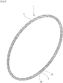
- a cable bead 1 according to this embodiment is a coreless ring-shaped cable bead 1.
- the cable bead 1 of this embodiment is described specifically.
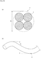
- Fig. 1 is a perspective view of the cable bead 1 of this embodiment
- Fig. 2 is a sectional perspective view of the cable bead 1.
- the cable bead 1 includes a single crimped strand 2 and a sleeve 3 with the two ends of the strand 2 inserted therein.
- the single strand 2 is wound four times of turns in a ring-shaped manner, thereby forming the cable bead 1.
- the cable bead 1, as shown in Fig. 2 includes four strands 2 in the radial-direction section thereof.
- the 1 x 4 x 1.20 single-twisted structure means that it includes four strands 2 each constituted of a single filament (steel wire) having a diameter of 1.20 mm.
- a single crimped strand member 2 crimped to constitute a 1 x 4 x 1.20 single-twisted structure is wound into a spiral-shaped gap part for storing three crimped strands 2 each crimped to constitute a 1 x 4 x 1.20 single-twisted structure and is wound four times of turns.
- an original cord 4 having a 1 x 4 x 1.20 single-twisted structure is wound on a bobbin while untwisting it by the strands 2, 2) one of the strands 2 wound on the bobbin is pulled out, the starting end side thereof is formed into a specific loop and the tip end of the starting end side is provisionally restricted to the loop, and 3), then, while revolving the bobbin, the pulled-out strand is wound into a gap part 9 (see Fig. 8 ) from which other strand member 2 has been removed, thereby forming the cable bead 1.
- a filament is wound on a dummy bar and is crimped to constitute an original cord 4 having a 1 x 4 x 1.20 single- twisted structure, 2) it is untwisted to provide a single crimped strand 2 crimped to constitute a 1 x 4 x 1.20 single- twisted structure, and 3) the single crimped strand 2 is wound into a spiral-shaped gap part for storing three other crimped strands 2 each crimped to constitute a 1 x 4 x 1.20 single-twisted structure and is wound four times of turns, thereby being also able to form the cable bead 1.
- the cable bead 1 of this embodiment is manufactured in such a manner that the strands 2 are each crimped into a spiral shape and are twisted together to form the original cord 4, the original cord 4 is untwisted by the respective strands 2, one of the untwisted strands 2 is used to produce a cable bead as if it had the same twist structure as the original cord 4, thereby enabling manufacture of the cable bead 1 by a simple method.
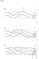
- the removal traces of the other strands 2 untwisted and removed are successively formed around the single strand 2 as the spiral-shaped gap parts 9. Also, the untwisted strands 2 are spirally crimped. Since the untwisted spiral-shaped strands 2 are wound into the spiral-shaped gap parts 9, the strands 2 are hard to interfere with each other, thereby reducing uneven twisting. Here, how to wind them spirally is described later specifically using Fig. 8 .
- Fig. 3 is a section view of an original cord 4 according to a reference example.
- a solid line shows strands 4
- a broken line shows the substantial outer peripheral surface 5 of the original cord 4 constituted of the strands 2.
- the substantial outer peripheral surface 5 is a virtual surface obtained when the outer-most circumferential side portions of the strands 2 are connected together over the whole circumference of the cable bead 1.
- the starting end 2a and finishing end 2b of the single crimped strand 2 are inserted into a cylindrical sleeve 3 and are connected together.
- the sleeve 3 while allowing the slight movement of the starting and finishing ends 2a and 2b of the strand 2 in the longitudinal direction of the strand 2, restricts the movement thereof in the diameter direction of the strand 2.
- the two ends of the single strand 2 constituting the cable bead 1 are freely movable, there is a fear that, when the cable bead 1 is embedded in a tire, the two ends can break through the rubber of the tire.
- Use of the cylindrical sleeve 3 as a connecting tool can prevent this fear simply and inexpensively.
- the cable bead 1 can be spread slightly in diameter, thereby enabling facilitation of mounting the cable bead 1 onto the wheel of the tire.
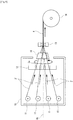
- Fig. 4 is a typical view of a step of producing the original cord 4.
- filaments 2' wound on bobbins 11 are discharged, are crimped spirally and are twisted together, thereby producing an original cord 4 having a 1 x 4 single-twisted structure.
- the filaments 2' wound on the bobbins 11 are non-crimped steel wires.
- the bobbins 11 with the filaments 2' wound thereon and a perforated board 12 are arranged within a cylindrical housing 10.
- the housing 10 is rotatable around a rotation axis Ax extending in the discharge direction of the filaments 2'.
- a twisting opening 13 and a winding bobbin 14 are arranged outside the housing 10.
- the filaments 2' While rotating the housing 10 around the rotation axis Ax and rotating the bobbins 11 and perforated board 12 integrally, the filaments 2' are discharged from the bobbins 11.
- the four filaments 2' discharged from the bobbins 11 are inserted through the four holes 12a of the perforated board 12 respectively.
- the four filaments 2' inserted through the holes 12a are gathered together in the twisting opening 13 and are crimped spirally and twisted together to thereby produce the original cord 4 having a 1 x 4 single-twisted structure; and, the original cord 4 is wound on the winding bobbin 14.
- the filaments are crimped by a preform device 16 so that the strand 2 can have a diameter formed ratio of 89% to 101%.
- the preform device 16 is interposed between the perforated board 12 and twisting opening 13 or between the bobbins 11 and perforated board 12.
- a postform device instead of the preform device 16, or, in addition to the perform device 16, there may also be used a postform device, whereby the filaments may be crimped so that the strand 2 can have a diameter formed ratio of 89% to 101%.
- previously crimped strands 2 may also be set on the bobbins 11.
- the twisting of the original cord 4 may be performed by either a tubular-type twisting machine or a buncher type twisting machine, when residual torsion stability and twist stability are taken into consideration, the tubular-type twisting machine may preferably be chosen.
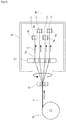
- Fig. 5 is a typical view of an untwisting step.
- the original cord 4 is untwisted by the strands 2 and the crimped strands 2 are wound one by one around the winding axis Ay of the bobbins 11, thereby providing the four spirally-crimped strands 2.
- the strands 2 are respectively constituted of a single filament 2'.
- the untwisting step can be performed by reversing the upstream and downstream of the device used in the original cord producing step described in Fig. 4 .
- the original cord 4 is discharged from the winding bobbins 14 and is inserted through the twisting opening 13 and the holes 12a of the perforated board 12.
- the perforated board 12 and bobbins 11 are rotated integrally relative to the twisting opening 13, the four crimped strands 2 are separated from each other and are wound one by one around the winding axis Ay of the bobbins 11.
- the bobbins 11 and perforated board 12 are rotated integrally around the rotation axis Ax extending in the discharge direction of the original cord 4.
- the strands 2 may be wound on the bobbins 11 with such low tension as can stretch the crimped strands 2 so that lowering of the diameter formed ratio can be limited to 2% or less.
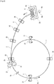
- Fig. 6 is a typical view of a loop forming step.
- One crimped strand 2 is discharged by a necessary length from the bobbin 11, the leading end side portion thereof is rounded in a ring-like shape to form a first-turn loop 7, and the leading end 2a thereof is provisionally restricted to the loop 7 with tape, etc.
- a winding device 20 is described later specifically.
- Fig. 7 is a typical view to show a state on the way of a winding step.
- the bobbin 11 is rotated around an axis crossing the winding axis Ay in the same direction
- the spirally rotating direction of the crimped strand 2 when the loop 7 is viewed from the bobbin 11 to torsionally discharge one crimped strand 2
- the loop 7 is rotated in the circumferential direction Bx to wind one discharged crimped strand 2 into a spiral-shaped gap with the other strand removed therefrom and wind it to the loop the (number of strands constituting the original cord 4 - 1) of turns.
- the details of this are described below.
- the winding step can be performed using the winding device 20 shown in Figs. 6 and 7 .
- the winding device 20, as shown in the figures, includes a first roller pair 21, a second roller pair 22, a winding guide 23, a ring shape maintaining guide 24, a strand guide 25 and a bobbin holder 26.
- the first roller pair 21 is a pair of roller pairs.
- the first roller pair 21 is arranged at two locations on the circumference of the loop 7.
- the first roller pair 21 rotates around a rotation axis extending in the vertical direction of the figure sheet.
- the first roller pair 21 is contacted with the crimped strand 2 to rotate the loop 7 counterclockwise in the sheet.
- the rotation direction of the loop 7 to be rotated by the first roller pair 21 is called a first direction Bx.
- the second roller pair 22 is a pair of roller pairs.
- the second roller pair 22 is arranged at a location on the circumference of the loop 7.
- the second roller pair 22 rotates around a rotation axis extending in the tangential direction of a point of contact with the crimped strand 2.
- the second roller pair 22 is contacted with the crimped strand 2 to rotate the crimped strand 2 constituting the loop 7 around an axis extending in the circumferential direction thereof.
- the second roller pair 22 rotates the loop 7 so that the inner and outer peripheral sides thereof are reversed.
- the rotation direction of the loop 7 to be rotated by the second roller pair 22 is called a second direction By.
- the ring shape maintaining guide 24 is arranged between the two first roller pairs 21 on the circumference of the loop 7, has a hole therein capable of insertion of the crimped strand 2, and maintains the shape of the loop 7 while allowing the crimped strand 2 to rotate in the first and second directions Bx and By.
- the winding guide 23 is also arranged on the circumference of the loop 7 at a position where an extra-length part 8 joins the loop 7, has a hole therein capable of insertion of the loop 7 and extra-length part 8, and allows the extra-length part 8 to join the loop 7.
- the winding guide 23 also has the function of the ring shape maintaining guide 24.
- the strand guide 25 guides the extra-length part 8 of the strand 2, has a hole therein capable of insertion of the extra-length part 8, and assists smooth winding of the strand 2 onto the loop 7 while allowing the crimped strand 2 to rotate in the first and second directions Bx and By.
- the bobbin holder 26 holds the bobbin 11 rotatably, rotates the bobbin 11 around an axis Az crossing the winding axis Ay of the bobbin 11, and rotates the bobbin 11 in the same direction Bz as the spiral rotation direction of the crimped strand 2 when the loop 7 is viewed from the bobbin 11, thereby discharging the wound crimped strand 2 to the loop 7.
- the crimped strand 2 draws a spiral counterclockwise toward the loop 7 when the loop 7 is viewed from the bobbin 11
- the bobbin holder discharges the crimped strand 2 while rotating the bobbin counterclockwise. Due to such rotation of the bobbin holder 26, the crimped strand 2 is discharged from the bobbin 11 while it is twisted such that its twisting is increased.
- the cable bead 1 is produced. Firstly, as shown in Fig. 6 , the original cord 4 is untwisted and the bobbin 11 with one crimped strand 2 wound thereon is set on the bobbin holder 26. From the loop 7, there is extended the extra-length part 8 of the strand 2 not used to form the loop 7 but including such portion as is wound on the bobbin 11.
- the crimped strand 2 is torsionally reeled out from the bobbin 11; and, the loop 7 is rotated in the first and second directions Bx, By by the first and second roller pairs 21 and 22 and, while winding the one discharged crimped strand 2 into the spiral-shaped gap with the other strand removed therefrom, the strand 2 is wound on the loop 7 (the number of strands constituting the original cord 4 - 1) times of turns (in this example, three times of turns).
- Fig. 8 shows how the extra-length part 8 is wound on the spiral-shaped gap 9 with the other strand 2 removed therefrom by the winding device 20.
- Fig. 8 is a partially enlarged perspective view of the loop 7.
- Fig. 8A shows the loop 7 formed when the strand 2 is wound once
- Fig. 8B shows the state of a one-turn strand 2 wound on the loop 7
- Fig. 8C shows the state of a two-turn strand 2 wound on the loop 7.
- Fig. 8A shows part of the loop 7 when the start end side portion of a crimped strand 2 provided by untwisting the original cord 4 is rounded into a ring shape and the strand 2 is wound one turn to thereby form the loop 7.
- the crimped strand 2 there are arranged three spiral-shaped gaps 9 which have been occupied by the three untwisted and removed strands 2.
- the bobbin 11 is rotated and, while rotating the loop 7 in the first and second directions Bx and By, the extra-length part 8 is inserted into the gap 9.
- the extra-length part 8 enters the gap 9 occupied by the untwisted and removed other one strand 2.
- the bobbin holder 26 is also rotated around the axis Az to rotate the crimped strand 2 around the axis Az and discharge it in a twisting increasing manner, whereby the rotation thereof in the second direction By by the second roller 22 is assisted. This can facilitate continuous winding of the extra-length part 8 of the strand 2 into the gap 9 with the other strand 2 removed therefrom.
- the extra-length part 8 enters the gap 9 occupied by the other untwisted and removed strand 2.
- the extra-length part 8 is wound in this manner (number of strands constituting the original cord 4 - 1) times of turns.
- the strand 2 is wound one more turn from the state of Fig. 8C (in the illustrated example, a total of three times of turns), thereby advancing to the next connecting step of Fig. 9 .
- the shape (pitch and crimp height) of the crimped strand 2 is similar to that of the gap 9, the crimped strand 2 is easy to enter the gap 9 and the crimped strands 2 are hard to interfere with each other.
- Fig. 9 shows the connecting step typically and is an enlarged perspective view of the start end 2a and terminal end 2b of the strand 2.
- the finishing end 2b of the crimped strand 2 is connected to the starting end 2a thereof, thereby enabling production of a cable bead 1 having a 1 x 4 1.20 single-twisted structure.
- the filament 2' to be discharged from the bobbin 11 may be replaced with a primary strand (1 x n) having an m x n double-twisted structure.
- the cable bead 1 can be manufactured by a simple method in which one strand 2 obtained by untwisting the original cord 4 after produced is wound on the loop 7 while winding the extra-length part 8 into the gap 9. Also, since the strands 2 are crimped when producing the original cord 4, the strong cable bead 1 can be produced. Further, since the crimped portions of the strands are prevented from interfering with each other, the cable bead 1 with less uneven twisting can be produced.
- the present invention is not limited to this.
- the processing may advance to the loop forming step.
- the above coreless cable bead can also be manufactured by a core-equipped cable bead manufacturing method disclosed, for example, in the patent document 2.
- the twist pitch of the original cord 4 may preferably be set large so long as the proper range (89% to 101%) of the diameter formed ratio can be adjusted easily.
- the twist pitch increases, when obtaining the crimped strands 2 by untwisting the original cord 4, the winding speed can be increased, thereby enabling time reduction.
- the twist pitch of the original cord 4 may preferably be adjusted such that the number of windings per turn is 9 ⁇ 19.
- the diameter formed ratio of the strand 2 provided by the following equation (2) may preferably be 89% ⁇ 101 %.
- ⁇ % Hs / Dc ⁇ 100
- the diameter formed ratio ⁇ (%) of the strand 2 is expressed by the above equation (2), where Hs expresses the height(mm) of the wave of the strand 2 obtained by non-load untwisting the original cord 4 and Dc expresses the outside diameter(mm) of the original cord 4. As the diameter formed ratio increases, the shape of the strand 2 is easier to be maintained in the spiral shape of the original cord 4.
- a cable bead is easy to produce and a cable bead of small elongation can be provided.
- Cable beads according to embodiments 6-1 ⁇ 9-3, 11-1 ⁇ 15-3 by the manufacturing method of the above mode, cable beads according to comparison examples 1-1 ⁇ 5-3, 10-1 ⁇ 10 ⁇ 3, 16-1 ⁇ 17-3, and conventional cable beads according to the conventional manufacturing methods are manufactured and evaluated.
- Element wires obtained by drawing a brass plated steel wire having a diameter of 8.0 mm and containing 0.7 mass% of C (carbon) to a diameter of 2.55 mm are wound on two bobbins.
- the element wires, after their diameter formed ratios are adjusted to 93% are twisted together by S twisting at the twist pitch of 50.0 mm, and are then wound on a winding bobbin, thereby producing an original cord.
- the respective strands are discharged from the winding bobbin with the original cord wound thereon and, while untwisting their finishing ends manually, are inserted through a perforated board and then are guided to bobbins.
- the crimped strands are wound on the bobbins by an untwisting device shown in Fig. 5 , thereby providing two strands for producing a coreless cable bead.
- One of the two strands provided by untwisting the original cord and wound on the bobbin is used.
- part of the strand is discharged from the bobbin to form a one-turn loop and the leading end of one discharged strand is provisionally restricted to the loop.
- the loop is rotated in the first and second directions to wind one discharged crimped strand into the spiral-shaped gap with the other strand removed therefrom, and is wound one turn on the loop. Further, the starting and finishing ends of the strand are connected together.
- Element wires obtained by drawing a brass plated steel wire having a diameter of 5.0 mm and containing 0.7 mass% of C up to a diameter of 1.48 mm are wound on three bobbins. Using a tubular type twisting machine, after adjusting their diameter formed ratios to 93%, they are twisted by Z twisting at a twist pitch of 35 mm, thereby producing primary strands.
- the primary strands (1 x 3 x 1.48) are wound by a specific amount on two bobbins.
- tubular type twisting machine again, after adjusting their diameter formed ratios to 91%, they are finally twisted by S twisting at a twist pitch of 65 mm, and an original cord is wound on the bobbin, thereby producing the original cord.
- the respective strands are discharged from the winding bobbin with the original cord wound thereon and, while manually untwisting their finishing ends, they are passed through the perforated board and are guided to a bobbin.
- the crimped strands are wound on the bobbins by the untwisting device shown in Fig. 5 , thereby providing two strands for producing a coreless cable bead.
- One of the two strands obtained by untwisting the original cord and wound on the bobbin is used.
- part of the strand is discharged from the bobbin to form a one-turn loop and the leading end of the discharged strand is provisionally restricted to the loop.
- the loop is rotated in the first and second directions to wind the discharged crimped strand into the spiral-shaped gap with the other strand removed therefrom and wind it on the one-turn loop. Further, the starting and finishing ends of the strand are connected together.
- Element wires obtained by drawing a brass plated steel wire having a diameter of 4.2 mm and containing 0.7 mass% of C to a diameter of 1.28 mm are wound on four bobbins. Using a tubular type twisting machine, after adjusting their diameter formed ratios to 93%, they are twisted by Z twist at a twist pitch of 35 mm, thereby producing primary twisted materials.
- the primary twisted materials (1 x 4 x 1.28) are wound by a specific amount on two bobbins. And, using the tubular type twisting machine again, after adjusting their diameter formed ratios to 91%, they are finally twisted by S twist at a twist pitch of 65 mm, and an original cord is wound on a winding bobbin, thereby producing the original cord.
- the respective strands are discharged from the winding bobbin with the original cord wound thereon and, with their finishing ends untwisted manually, they are passed through the perforated board and are guided to a bobbin.
- the strands crimped by the untwisting device shown in Fig. 5 are wound on the bobbin, thereby providing two strands for producing a coreless cable bead.
- One of the two strands obtained by untwisting the original cord and wound on the bobbin is used.
- part of the strand is discharged from the bobbin to form a one-turn loop and the leading end of the discharged strand is provisionally restrained to the loop.
- the loop is rotated in the first and second directions to wind the discharged crimped strand into the spiral-shaped gap with the other strand removed therefrom and wind it on the one-turn loop. Further, the starting and finishing ends of the strand are connected together.
- Element wires obtained by drawing a brass plated steel wire having a diameter of 4.2 mm and containing 0.7 mass% of C to a diameter of 1.15 mm are wound on three bobbins. Using a tubular type twisting machine, after adjusting their diameter formed ratios to 92%, they are twisted by Z twist at a twist pitch of 38 mm.
- the thus-produced primary twisted materials (1 x 5 x 1.15) are wound by a specific amount on two bobbins. And, using the tubular type twisting machine again, after adjusting their diameter formed ratios to 91%, they are finally twisted by S twist at a twist pitch of 50 mm, and an original cord is wound on the winding bobbin, thereby producing the original cord.
- the respective strands are discharged from the winding bobbin with the original cord wound thereon and, with their finishing ends untwisted manually, they are passed through the perforated board and are guided to a bobbin.
- the strands crimped by the untwisting device shown in Fig. 5 are wound on the bobbin, thereby providing two strands for producing a coreless cable bead.
- One of the two strands obtained by untwisting the original cord and wound on the bobbin is used.
- part of the strand is discharged from the bobbin to form a one-turn loop and the starting end of the discharged strand is provisionally restrained to the loop.
- the loop is rotated in the first and second directions to wind the discharged crimped strand into the spiral-shaped gap with the other strand removed therefrom and wind it on the one-turn loop. Further, the starting and finishing ends of the strand are connected together.
- Element wires obtained by drawing a brass plated steel wire having a diameter of 3.2 mm and containing 0.7 mass% of C to a diameter of 0.97 mm are wound on seven bobbins. Using a tubular type twisting machine, after adjusting their diameter formed ratios to 95%, they are twisted by Z twisting at a twist pitch of 40 mm.
- the thus-produced primary twisted materials (1 x 7 x 0.97) are wound by a specific amount on two bobbins. And, using the tubular type twisting machine again, after adjusting their diameter formed ratios to 91%, they are finally twisted by S twisting at a twist pitch of 60 mm, and an original cord is wound on the winding bobbin, thereby producing the original cord.
- the respective strands are discharged from the winding bobbin with the original cord wound thereon and, with their finishing ends untwisted manually, they are passed through the perforated board and are guided to a bobbin.
- the strands crimped by the untwisting device shown in Fig. 5 are wound on the bobbin, thereby providing two strands for producing a coreless cable bead.
- One of the two strands obtained by untwisting the original cord and wound on the bobbin is used.
- part of the strand is discharged from the bobbin to form a one-turn loop and the starting end of the discharged strand is provisionally restrained to the loop.
- the loop is rotated in the first and second directions to wind the discharged crimped strand into the spiral-shaped gap with the other strand removed therefrom and wind it on the one-turn loop. Further, the starting and finishing ends of the strand are connected together.
- Element wires obtained by drawing a brass plated steel wire having a diameter of 6.5 mm and containing 0.7 mass% of C to a diameter of 2.10 mm are wound on three bobbins.
- a tubular type twisting machine After adjusting their diameter formed ratios to 95%, they are twisted by S twisting at a twist pitch of 50.0 mm and are wound on a bobbin, thereby producing an original cord.
- the respective strands are reeled out from the winding bobbin with the original cord wound thereon and, with their finishing ends untwisted manually, they are passed through the perforated board and are guided to a bobbin.
- the strands crimped by the untwisting device shown in Fig. 5 are wound on the bobbin, thereby providing three strands for producing a coreless cable bead.
- One of the three strands obtained by untwisting the original cord and wound on the bobbin is used.
- part of the strand is discharged from the bobbin to form a one-turn loop and the starting end of the discharged strand is provisionally restrained to the loop.
- the loop is rotated in the first and second directions to wind the discharged crimped strand into the spiral-shaped gap with the other strand removed therefrom and wind it on loop by two turns. Further, the starting and finishing ends of the strand are connected together.
- Element wires obtained by drawing a brass plated steel wire having a diameter of 5.0 mm and containing 0.7 mass% of C to a diameter of 1.48 mm are wound on two bobbins. Using a tubular type twisting machine, after adjusting their diameter formed ratios to 95%, they are twisted by Z twisting at a twist pitch of 30 mm.
- the thus-produced primary twisted materials (1 x 2 x 1.48) are wound by a specific amount on three bobbins. And, using the tubular type twisting machine again, after adjusting their diameter formed ratios to 92%, they are finally stranded by S twisting at a twist pitch of 70 mm, and an original cord is wound on the winding bobbin, thereby producing the original cord.
- the respective strands are discharged from the winding bobbin with the original cord wound thereon and, with their finishing ends untwisted manually, they are passed through the perforated board and are guided to a bobbin.
- the strands crimped by the untwisting device shown in Fig. 5 are wound on the bobbin, thereby providing three strands for producing a coreless cable bead.
- One of the three strands obtained by untwisting the original cord and wound on the bobbin is used.
- part of the strand is discharged from the bobbin to form a one-turn loop and the starting end of the discharged strand is provisionally restrained to the loop.
- the loop is rotated in the first and second directions to wind the discharged crimped strand into the spiral-shaped gap with the other strand removed therefrom and wind it on the loop by two turns. Further, the starting and finishing ends of the strand are connected together.
- Element wires obtained by drawing a brass plated steel wire having a diameter of 4.5 mm and containing 0.7 mass% of C to a diameter of 1.20 mm are wound on three bobbins. Using a tubular type twisting machine, after adjusting their diameter formed ratios to 92%, they are stranded by Z twisting at a twist pitch of 25 mm.
- the thus-produced primary twisted materials (1 x 3 x 1.20) are wound by a specific amount on three bobbins. And, using the tubular type twisting machine again, after adjusting their diameter formed ratios to 99%, they are finally twisted by S twisting at a twist pitch of 60 mm, and an original cord is wound on the winding bobbin, thereby producing the original cord.
- the respective strands are discharged from the winding bobbin with the original cord wound thereon and, with their finishing ends untwisted manually, they are passed through the perforated board and are guided to a bobbin.
- the strands crimped by the untwisting device shown in Fig. 5 are wound on the bobbin, thereby providing three strands for producing a coreless cable bead.
- One of the three strands obtained by untwisting the original cord and wound on the bobbin is used.
- part of the strand is discharged from the bobbin to form a one-turn loop and the starting end of the discharged strand is provisionally restrained to the loop.
- the loop is rotated in the first and second directions to wind the discharged crimped strand into the spiral-shaped gap with the other strand removed therefrom and wind it on the loop by two turns. Further, the starting and finishing ends of the strand are connected together.
- Element wires obtained by drawing a brass plated steel wire having a diameter of 4.5 mm and containing 0.7 mass% of C to a diameter of 1.05 mm are wound on four bobbins. Using a tubular type twisting machine, after adjusting their diameter formed ratios to 94%, they are twisted by Z twisting at a twist pitch of 30 mm.
- the thus-produced primary twisted materials (1 x 4 x 1.05) are wound by a specific amount on three bobbins. And, using the tubular type twisting machine again, after adjusting their diameter formed ratios to 93%, they are finally twisted by S twisting at a twist pitch of 60 mm, and an original cord is wound on the winding bobbin, thereby producing the original cord.
- the respective strands are discharged from the winding bobbin with the original cord wound thereon and, with their finishing ends untwisted manually, they are passed through the perforated board and are guided to a bobbin.
- the strands crimped by the untwisting device shown in Fig. 5 are wound on the bobbin, thereby providing three strands for producing a coreless cable bead.
- One of the three strands obtained by untwisting the original cord and wound on the bobbin is used.
- part of the strand is discharged from the bobbin to form a one-turn loop and the starting end of the discharged strand is provisionally restrained to the loop.
- the loop is rotated in the first and second directions to wind the discharged crimped strand into the spiral-shaped gap with the other strand removed therefrom and wind it on the loop by two turns. Further, the starting and finishing ends of the strand are connected together.
- Element wires obtained by drawing a brass plated steel wire having a diameter of 3.0 mm and containing 0.7 mass% of C to a diameter of 0.85 mm are wound on six bobbins. Using a tubular type twisting machine, after adjusting their diameter formed ratios to 91 %, they are twisted by Z twisting at a twist pitch of 33 mm.
- the thus-produced primary twisted materials (1 x 6 x 0.85) are wound by a specific amount on three bobbins. And, using the tubular type twisting machine again, after adjusting their diameter formed ratios to 96%, they are finally twisted by S twisting at a twist pitch of 60 mm, and an original cord is wound on the winding bobbin, thereby producing the original cord.
- the respective strands are discharged from the winding bobbin with the original cord wound thereon and, with their finishing ends untwisted manually, they are passed through the perforated board and are guided to a bobbin.
- the strands crimped by the untwisting device shown in Fig. 5 are wound on the bobbin, thereby providing three strands for producing a coreless cable bead.
- One of the three strands obtained by untwisting the original cord and wound on the bobbin is used.
- part of the strand is discharged from the bobbin to form a one-turn loop and the leading end of the discharged strand is provisionally restrained to the loop.
- the loop is rotated in the first and second directions to wind the discharged crimped strand into the spiral-shaped gap with the other strand removed therefrom and wind it on the loop by two turns. Further, the starting and finishing ends of the strand are connected together.
- Element wires obtained by drawing a brass plated steel wire having a diameter of 2.6 mm and containing 0.7 mass% of C to a diameter of 0.78 mm are wound on seven bobbins. Using a tubular type twisting machine, after adjusting their diameter formed ratios to 97%, they are twisted by Z twisting at a twist pitch of 34 mm.
- the thus-produced primary twisted materials (1 x 7 x 0.78) are wound by a specific amount on three bobbins. And, using the tubular type twisting machine again, after adjusting their diameter formed ratios to 94%, they are finally twisted by S twisting at a twist pitch of 60 mm, and an original cord is wound on the winding bobbin, thereby producing the original cord.
- the respective strands are discharged from the winding bobbin with the original cord wound thereon and, with their finishing ends untwisted manually, they are passed through the perforated board and are guided to a bobbin.
- the strands crimped by the untwisting device shown in Fig. 5 are wound on the bobbin, thereby providing three strands for producing a coreless cable bead.
- One of the three strands obtained by untwisting the original cord and wound on the bobbin is used.
- part of the strand is discharged from the bobbin to form a one-turn loop and the starting end of the discharged strand is provisionally restrained to the loop.
- the loop is rotated in the first and second directions to wind the discharged crimped strand into the spiral-shaped gap with the other strand removed therefrom and wind it on the loop by two turns. Further, the starting and finishing ends of the strand are connected together.
- Element wires obtained by drawing a brass plated steel wire having a diameter of 4.2 mm and containing 0.7 mass% of C to a diameter of 1.28 mm are wound on two bobbins. Using a tubular type twisting machine, after adjusting their diameter formed ratios to 95%, they are twisted by Z twisting at a twist pitch of 25 mm.
- the thus-produced primary twisted materials (1 x 3 x 1.28) are wound by a specific amount on four bobbins. And, using the tubular type twisting machine again, after adjusting their diameter formed ratios to 97%, they are finally twisted by S twisting at a twist pitch of 70 mm, and an original cord is wound on the winding bobbin, thereby producing the original cord.
- the respective strands are discharged from the winding bobbin with the original cord wound thereon and, with their finishing ends untwisted manually, they are passed through the perforated board and are guided to a bobbin.
- the strands crimped by the untwisting device shown in Fig. 5 are wound on the bobbin, thereby providing three strands for producing a coreless cable bead.
- One of the four strands obtained by untwisting the original cord and wound on the bobbin is used.
- part of the strand is discharged from the bobbin to form a one-turn loop and the starting end of the discharged strand is provisionally restrained to the loop.
- the loop is rotated in the first and second directions to wind the discharged crimped strand into the spiral-shaped gap with the other strand removed therefrom and wind it on the loop by three turns. Further, the starting and finishing ends of the strand are connected together.
- Element wires obtained by drawing a brass plated steel wire having a diameter of 3.6 mm and containing 0.7 mass% of C to a diameter of 1.05 mm are wound on three bobbins. Using a tubular type twisting machine, after adjusting their diameter formed ratios to 96%, they are twisted by Z twisting at a twist pitch of 25 mm.
- the thus-produced primary twisted materials (1 x 3 x 1.05) are wound by a specific amount on four bobbins. And, using the tubular type twisting machine again, after adjusting their diameter formed ratios to 97%, they are finally twisted by S twisting at a twist pitch of 65 mm, and an original cord is wound on the winding bobbin, thereby producing the original cord.
- the respective strands are discharged from the winding bobbin with the original cord wound thereon and, with their finishing ends untwisted manually, they are passed through the perforated board and are guided to a bobbin.
- the strands crimped by the untwisting device shown in Fig. 5 are wound on the bobbin, thereby providing four strands for producing a coreless cable bead.
- One of the four strands obtained by untwisting the original cord and wound on the bobbin is used.
- part of the strand is discharged from the bobbin to form a one-turn loop and the starting end of the discharged strand is provisionally restrained to the loop.
- the loop is rotated in the first and second directions to wind the discharged crimped strand into the spiral-shaped gap with the other strand removed therefrom and wind it on the loop by three turns. Further, the starting and finishing ends of the strand are connected together.
- Element wires obtained by drawing a brass plated steel wire having a diameter of 5.3 mm and containing 0.7 mass% of C to a diameter of 1.60 mm are wound on five bobbins.
- a tubular type twisting machine After adjusting their diameter formed ratios to 97%, they are twisted by S twisting at a twist pitch of 55.0 mm and are wound on the bobbin, thereby producing an original cord.
- the respective strands are discharged from the winding bobbin with the original cord wound thereon and, with their finishing ends untwisted manually, they are passed through the perforated board and are guided to a bobbin.
- the strands crimped by the untwisting device shown in Fig. 5 are wound on the bobbin, thereby providing five strands for producing a coreless cable bead.
- One of the five strands obtained by untwisting the original cord and wound on the bobbin is used.
- part of the strand is discharged from the bobbin to form a one-turn loop and the starting end of the discharged strand is provisionally restrained to the loop.
- the loop is rotated in the first and second directions to wind the discharged crimped strand into the spiral-shaped gap with the other strand removed therefrom and wind it on the loop by four turns. Further, the starting and finish ends of the strand are connected together.
- Element wires obtained by drawing a brass plated steel wire having a diameter of 4.2 mm and containing 0.7 mass% of C up to a diameter of 1.15 mm are wound on two bobbins. Using a tubular type twisting machine, after adjusting their diameter formed ratios to 97%, they are twisted by Z twisting at a twist pitch of 17.5 mm.
- the thus-produced primary twisted materials (1 x 2 x 1.15) are wound by a specific amount on five bobbins. And, using the tubular type twisting machine again, after adjusting their diameter formed ratios to 93%, they are finally twisted by S twisting at a twist pitch of 70 mm, and an original cord is wound on the winding bobbin, thereby producing the original cord.
- the respective strands are discharged from the winding bobbin with the original cord wound thereon and, with their finishing ends untwisted manually, they are passed through the perforated board and are guided to a bobbin.
- the strands crimped by the untwisting device shown in Fig. 5 are wound on the bobbin, thereby providing five strands for producing a coreless cable bead.
- One of the five strands obtained by untwisting the original cord and wound on the bobbin is used.
- part of the strand is discharged from the bobbin to form a one-turn loop and the starting end of the discharged strand is provisionally restrained to the loop.
- the loop is rotated in the first and second directions to wind the discharged crimped strand into the spiral-shaped gap with the other strand removed therefrom and wind it on the loop by four turns. Further, the starting and finishing ends of the strand are connected together.
- Element wires obtained by drawing a brass plated steel wire having a diameter of 5.0 mm and containing 0.7 mass% of C to a diameter of 1.47 mm are wound on six bobbins. Using a tubular type twisting machine, after adjusting their diameter formed ratios to 99%, they are twisted by S twisting at a twist pitch of 60 mm and are wound on the bobbins, thereby producing an original cord.
- the respective strands are discharged from the winding bobbin with the original cord wound thereon and, with their finishing ends untwisted manually, they are passed through the perforated board and are guided to a bobbin.
- the strands crimped by the untwisting device shown in Fig. 5 are wound on the bobbins, thereby providing six strands for producing a coreless cable bead.
- One of the six strands obtained by untwisting the original cord and wound on the bobbins is used.
- part of the strand is discharged from the bobbin to form a one-turn loop and the starting end of the discharged strand is provisionally restrained to the loop.
- the loop is rotated in the first and second directions to wind the discharged crimped strand into the spiral-shaped gap with the other strand removed therefrom and wind it on the loop by five turns. Further, the starting and finishing ends of the strand are connected together.
- Element wires each obtained by drawing a brass plated steel wire having a diameter of 3.0 mm and containing 0.7 mass% of C to a diameter of 0.85 mm is wound on three bobbins. Using a tubular type twisting machine, after adjusting their diameter formed ratios to 96%, they are twisted by Z twisting at a twist pitch of 20 mm.
- the thus-produced primary twisted materials (1 x 3 x 0.85) are wound by a specific amount on six bobbins. And, using the tubular type twisting machine again, after adjusting their diameter formed ratios to 93%, they are finally twisted by S twisting at a twist pitch of 70 mm, and an original cord is wound on the winding bobbin, thereby producing the original cord.
- the respective strands are discharged from the winding bobbins with the original cord wound thereon and, with their finishing ends untwisted manually, they are passed through the perforated board and are guided to bobbins.
- the strands crimped by the untwisting device shown in Fig. 5 are wound on the bobbins, thereby providing six strands for producing a coreless cable bead.
- One of the six strands obtained by untwisting the original cord and wound on the bobbins is used.
- part of the strand is discharged from the bobbin to form a one-turn loop and the starting end of the discharged strand is provisionally restrained to the loop.
- the loop is rotated in the first and second directions to wind the discharged crimped strand into the spiral-shaped gap with the other strand removed therefrom and wind it on the loop by five turns. Further, the starting and finishing ends of the strand are connected together.
- An element wire obtained by drawing a brass plated steel wire having a diameter of 6.0 mm and containing 0.52 mass % of C to a diameter of 2.2 mm is rounded to form a loop having a ring-shaped center diameter of 310 mm, the two ends thereof are butted against each other, and, after welding, burrs are removed therefrom, thereby producing a ring-shaped core material.
- An element wire obtained by drawing a brass plated steel wire having a diameter of 5.0 mm and containing 0.7 mass % of C to a diameter of 1.40 mm is wound on a large bobbin.
- the element wire is suppled from the large bobbin and is wound on an exclusive small bobbin through a correcting roller for line crimping, thereby producing a strand.
- the core ring is set in a conventional cable bead manufacturing apparatus (see, for example, JPA Publication No. 2008-240223 ), the strand is supplied from the exclusive small bobbin, the strand is supplied and is pulled out to the core ring, and its starting end is provisionally fixed to the core ring with tape, etc.
- the cable bead manufacturing apparatus while passing a bobbin with the strand wound thereon through the core ring, the bobbin is turned eight times horizontally and at right angles, and, finally, the two ends of the strand are inserted into a cylindrical sleeve and connected together, thereby producing a conventional core-equipped cable bead.
- ⁇ c average crimped hight / average cord diameter ⁇ 100
- the cord obtained in order to measure the diameter formed ratio was passed through a dice having a hole of a diameter 1.05 times the cord diameter. When the cord could pass over the whole length, it is determined that it has "no uneven twisting", and when not, it is determined that it has "uneven twisting". This test was repeated fifty times and the ratio of the number of times of no uneven twisting is shown in Table 1 and 2.
- the manufacturing time of the conventional cable bead was obtained as follows.
- the time to form the core into a specific ring-shape diameter Starting from the time to supply the core material, the time to form the core into a specific ring-shape diameter, the time to butt the two ends against each other, the time to weld them and the time to remove burrs were totaled.
- the time to give a specific crimped line (including adjusting time), the time to wind it on the exclusive bobbin, and the time to take it up were totaled.
- the core-equipped cable bead manufacturing apparatus starting the time to set the core material, the time to supply the exclusive bobbin with the strand wound thereon, the time to discharge the strand to the core material, the time for adjustment, and the time to complete the cable bead were totaled.
- the time to supply the element wire to the twisting machine, the time to wind the strand on the bobbin and the time to take it up were totaled.
- the primary twisting and final twisting were both counted.
- the coreless cable bead manufacturing apparatus starting from the time to set the bobbin with the strand wound thereon in the supply device and the time to complete the cable bead were totaled.
- the average hardness was obtained as follows.
- the indexes having (a) of the indexes of the conventional example 1, comparison example 1-1, etc. show indexes when the hardness of the rubber surface of a rubber composite using a round rod a of ⁇ 5.0 mm is assumed as 100.
- Rubber used rubber for tire (1 mm thickness sheet), vulcanization condition: 150°C x 30 minutes, and vulcanization pressure: 10 kg/cm 2 .
- Tables 1 and 2 show that the embodiments 6 ⁇ 9 and 11 ⁇ 15, while reducing manufacturing time, can restrict uneven twisting occurrence when compared with the conventional examples.
- the present invention provides a cable bead which can be manufactured in a short time and is hard to cause uneven twisting.
Landscapes
- Engineering & Computer Science (AREA)
- Mechanical Engineering (AREA)
- Ropes Or Cables (AREA)
- Tyre Moulding (AREA)
- Tires In General (AREA)
Abstract
Description
- The present invention relates to a cable bead for use in a vehicle tire and a method for manufacturing the same.
- Conventionally, there is known a method in which a large-diameter filament made of soft steel is formed into a ring-shaped member and, after then, with the ring-shaped member as a core, a small-diameter filament is wound around the periphery of the core, thereby manufacturing a cable bead. However, in this method, the number of winding turns of the small-diameter filament is large to thereby increase the cable bead manufacturing time. In view of this, the
patent document 1 proposes a cable bead having no core. That is, in thepatent document 1, a single steel filament is formed into a ring-shaped member and the ring-shaped filament is wound multiple times and twisted together, thereby manufacturing a cable bead. Thus, the diameter of a single filament used as a so-called 1 x n single-twisted structure can be increased and the number of filament winding turns can be reduced accordingly, thereby enabling inexpensive manufacture of a cable bead. - The
patent document 2 discloses a cable bead manufacturing method in which a soft-steel filament is used as an inner core and a crimped small-diameter filament is spirally wound around it to thereby form a cable bead. That is, the previously crimped small-diameter filament having a radius at least more than double the radius of the ring-shaped core is wound around the soft-steel filament serving as the core. This method can provide a stiff cable bead. -
- Patent Document 1:
JP-A-H09-273088 - Patent Document 2:
JP-A-H07-68662 - In the method of the
patent document 1, since the single large-diameter filament is not crimped, particularly, the small-diameter filament formed first in a ring shape tends to provide a core line not a side line and may have a core-equipped 1 + (m-1) structure not a coreless 1 x m structure, which takes time to correct it, thereby increasing manufacturing cost. - In the method of the
patent document 2, when a crimped small-diameter filament is wound around the core, since the crimped portion of the small-diameter filament is caught by the core, uneven twisting is easy to occur, thereby causing uneven winding and thus causing a space for the last winding to disappear. - Here, although it is expected that, when the diameter-direction crimping height of the small-diameter filament is reduced, winding can be performed smoothly, it is difficult to maintain even and stable crimping height.
- Thus, the present invention has an object to provide a cable bead capable of reducing manufacturing time and hard to cause uneven twisting, and a method for manufacturing the same.
- The present invention provides a coreless ring-shaped cable bead, wherein a single strand crimped so as to have a 1 x m1 x d1 single-twisted structure or a m2 x n x d2 double-twisted structure is wound into a spiral-shaped gap part for storing (m1 - 1) or (m2 - 1) number of crimped strands having the above structure and is wound m1 or m2 times of twists. Here, the number of twists, m1, m2 and n satisfy the following equation: that is, 3≤m1≤5, 3≤m2≤5, 2≤n≤5, and n=7(1+6), 11(3+8) or 12(3+9), where m1: number of twists in the single-twisted structure, d1: diameter of filament constituting the single-twisted structure, m2: number of final twists in the double-twisted structure, n: number of primary twists in the double-twisted structure, and d2: diameter of filament constituting the double-twisted structure.
- Here, in the present invention, the double-twisted structure includes two kinds of twisting, that is, primary twisting (performed primarily) and final twisting (performed secondarily).
- The present invention provides a method for manufacturing a cable bead, comprising the steps of: supplying multiple filaments to a twisting machine and, after the strand is adjusted by a pre-forming device and/or a post-forming device to have a diameter formed ratio of 89 ~ 101%, twisting them together to produce an original cord; untwisting the original cord by the strands and winding the crimped strands one by one around the winding axis of a bobbin; discharging part of one of the crimped (formed) strands from the bobbin to form a one-turn loop, and provisionally restricting the leading end of the single crimped strand to the loop; twistingly rotating the bobbin around an axis crossing the winding axis in the same direction of the spiral rotation direction of the crimped strand when the loop is viewed from the bobbin to discharge the single crimped strand, and rotating the loop in the peripheral direction to wind the single discharged crimped strand into a spiral-shaped gap part with the other strand removed therefrom and winding it on the loop (the number of strands constituting the original cord - 1) times of turns; and, connecting together the starting and finishing ends of the strand.
- The present invention provides a cable bead capable of reducing manufacturing time and hard to cause uneven twisting, and a method for manufacturing the same.
-
- [
Fig. 1 ] It is a perspective view of a cable bead according to an embodiment of the present invention. - [
Fig. 2 ] It is a section view of the cable bead shown inFig. 1 . - [
Fig. 3 ] It is a section view of an original cord for manufacturing a cable bead according to a reference example. - [
Fig. 4 ] It is a typical view of the step of producing the original cord. - [
Fig. 5 ] It is a typical view of the untwisting step. - [
Fig. 6 ] It is a typical view of the loop forming step. - [
Fig. 7 ] It is a typical view of the winding step. - [
Fig. 8 ] It is a perspective view of part of a cable bead in the winding step. - [
Fig. 9 ] It is a typical view of the finishing end connecting step. - [
Fig. 10 ] It is an explanatory view of the diameter formed ratio. - Firstly, description is given of the summary of the embodiment of the present invention.
- An embodiment of a cable bead according to the present invention provides (1) a coreless ring-shaped cable bead in which a single crimped strand crimped so as to constitute a 1 x m1 x d1 single-twisted structure or an m2 x n x d2 double-twisted structure is wound into a spiral-shaped gap part for storing (m1 - 1) or (m2 - 1) number of crimped strands constituting the above structure and is wound m1 or m2 times of turns.
- Here, the number of twists, m1, m2 and n satisfy the following equations: 3 ≤ m1 ≤ 5, 3 ≤ m2 ≤ 5, 2 ≤ n ≤ 5 and n = 7 (1 + 6), 11 (3 + 8) or 12 (3 + 9), where m1: number of twists in single-twisted structure, d1: diameter of filament constituting single-twisted structure, m2: number of final twists in double-twisted structure, n: number of primary twists in double-twisted structure, and d2: diameter of filament constituting double-twisted structure.
- In the cable bead according to the structure of (1), the single crimped strand is wound into the spiral-shaped gap part for storing (m1 - 1) or (m2 - 1) number of crimped strands constituting the 1 x m1 x d1 single-twisted structure or the m2 x n x d2 double-twisted structure and is wound m1 or m2 times of turns. Thus, the crimped portions of the strands are hard to interfere with each other, thereby enabling production of a cable bead of less uneven twisting.
-
- (2) In the double-twisted structure of the original cord, the diameter formed ratio of the strand given by the following equation may also be 89% to 101 %.
φ(%) = Hs/Dc x 100, where φ: diameter formed ratio(%) of the above strand, Hs: height(mm) of wave of the strand obtained when the original cord is no-load untwisted, and Dc: outside diameter (mm) of the original cord.
According to the structure of (2), there can be obtained a cable bead easy to manufacture and of less elongation. - (3) In the double-twisted structure of the original cord, the two ends of the single crimped strand may also be inserted into a cylindrical sleeve and connected together there.
- According to the structure (3), the finishing end of the strand can be processed with a simple structure and the ends of the strand are prevented from damaging a tire.
- An embodiment of a cable bead manufacturing method according to the present invention provides (4) a method, comprising the steps of: supplying multiple filaments to a twisting machine and, after the strand is adjusted by a pre-forming device and/or a post-forming device to have a diameter formed ratio of 89 ~ 101%, twisting them together to produce an original cord; untwisting the original cord by the strands and winding the crimped strands one by one around the winding axis of a bobbin; discharging part of one of the crimped strands from the bobbin to form a one-turn loop, and provisionally restricting the starting end of the single crimped strand to the loop; twistingly rotating the bobbin around an axis crossing the winding axis in the same direction of the spiral rotation direction of the crimped strand when the loop is viewed from the bobbin to discharge the single crimped strand, and rotating the loop in the peripheral direction to wind the single discharged crimped strand into a spiral-shaped gap part with the other strand removed therefrom and winding it on the loop (the number of strands constituting the original cord - 1) times of turns; and, connecting together the starting and finishing ends of the strand.
- According to the structure of (4), a cable bead of less uneven twisting can be manufactured using a simple method.
- Description is given below of embodiments of a cable bead according to the present invention with reference to the drawings. Here, the present invention is not limited to the illustrated embodiments but contains all changes falling under the scope of the patent claims and falling within the meanings and ranges equivalent to the scope of the patent claims.
- A
cable bead 1 according to this embodiment is a coreless ring-shaped cable bead 1. UsingFigs. 1 and2 , thecable bead 1 of this embodiment is described specifically.Fig. 1 is a perspective view of thecable bead 1 of this embodiment, andFig. 2 is a sectional perspective view of thecable bead 1. - The illustrated
cable bead 1 has a 1 x 4 x 1.20 single- twisted structure of m1 = 4 (twists) and d1 = 1.20 (mm). Thecable bead 1 includes a single crimpedstrand 2 and asleeve 3 with the two ends of thestrand 2 inserted therein. Thesingle strand 2 is wound four times of turns in a ring-shaped manner, thereby forming thecable bead 1. Thecable bead 1, as shown inFig. 2 , includes fourstrands 2 in the radial-direction section thereof. - Here, the 1 x 4 x 1.20 single-twisted structure means that it includes four
strands 2 each constituted of a single filament (steel wire) having a diameter of 1.20 mm. - In this
cable bead 1, a single crimpedstrand member 2 crimped to constitute a 1 x 4 x 1.20 single-twisted structure is wound into a spiral-shaped gap part for storing three crimpedstrands 2 each crimped to constitute a 1 x 4 x 1.20 single-twisted structure and is wound four times of turns. - For example, 1) an
original cord 4 having a 1 x 4 x 1.20 single-twisted structure is wound on a bobbin while untwisting it by thestrands 2, 2) one of thestrands 2 wound on the bobbin is pulled out, the starting end side thereof is formed into a specific loop and the tip end of the starting end side is provisionally restricted to the loop, and 3), then, while revolving the bobbin, the pulled-out strand is wound into a gap part 9 (seeFig. 8 ) from whichother strand member 2 has been removed, thereby forming thecable bead 1. - Or, a filament is wound on a dummy bar and is crimped to constitute an
original cord 4 having a 1 x 4 x 1.20 single- twisted structure, 2) it is untwisted to provide a single crimpedstrand 2 crimped to constitute a 1 x 4 x 1.20 single- twisted structure, and 3) the single crimpedstrand 2 is wound into a spiral-shaped gap part for storing three other crimpedstrands 2 each crimped to constitute a 1 x 4 x 1.20 single-twisted structure and is wound four times of turns, thereby being also able to form thecable bead 1. - The
cable bead 1 of this embodiment is manufactured in such a manner that thestrands 2 are each crimped into a spiral shape and are twisted together to form theoriginal cord 4, theoriginal cord 4 is untwisted by therespective strands 2, one of theuntwisted strands 2 is used to produce a cable bead as if it had the same twist structure as theoriginal cord 4, thereby enabling manufacture of thecable bead 1 by a simple method. - Also, when the
original cord 3 is untwisted, the removal traces of theother strands 2 untwisted and removed are successively formed around thesingle strand 2 as the spiral-shapedgap parts 9. Also, the untwistedstrands 2 are spirally crimped. Since the untwisted spiral-shapedstrands 2 are wound into the spiral-shapedgap parts 9, thestrands 2 are hard to interfere with each other, thereby reducing uneven twisting. Here, how to wind them spirally is described later specifically usingFig. 8 . - In the
cable bead 1 of this embodiment, the numbers of twists m1, m2 and n of the twisted structure of theoriginal cord 4 satisfy the following equation (1), that is, 3 ≤ m1 ≤ 5, 3 ≤ m2 ≤ 5, 2 ≤ n ≤ 5, and n = 7 (1+6), 11 (3+8) or 12 (13+9). - Here, n = 7 (1+6) shows a mode in which, in the section of the
original cord 4, a single filament is arranged in the center and six filaments are arranged around it. Similarly, n = 11 (3+8) shows a mode in which, in the section of theoriginal cord 4, three filaments are arranged in the center and eight filaments are arranged around them. And, n = 12 (3+9) shows a mode in which, in the section of theoriginal cord 4, three filaments are arranged in the center and nine filaments are arranged around them. -
Fig. 3 is a section view of anoriginal cord 4 according to a reference example. InFig. 3 , a solid line showsstrands 4, while a broken line shows the substantial outerperipheral surface 5 of theoriginal cord 4 constituted of thestrands 2. The substantial outerperipheral surface 5 is a virtual surface obtained when the outer-most circumferential side portions of thestrands 2 are connected together over the whole circumference of thecable bead 1. - For example, as shown in
Fig. 3A , in an original cord constituted of twostrands 2, there are locations where the outer circumferential surfaces of thestrands 2 drop down toward the inside diameter side greatly from the substantial outercircumferential surface 5 of theoriginal cord 4, thereby forming great uneven portions on the surface of theoriginal cord 4. Since the section shape of acable bead 1 provided by suchoriginal cord 4 is also substantially the same as that of theoriginal cord 4, the uneven portions of the surface of thecable bead 1 produced from suchoriginal cord 4 become large. When thiscable bead 1 is used in the bead part of a tire as a reinforcing member, uneven close contact occurs between thecable bead 1 and the rim of a tire wheel, thereby causing leakage of air. - Or, as shown in
Fig. 3B , when sixstrands 2 exist in the section of theoriginal cord 4, alarge cavity 6 is formed in the center of the section. Thus, in twisting theoriginal code 4, thestrands 2 can enter thecavity 6, thereby causing uneven twisting. - However, in the
cable bead 1 having a twisted structure satisfying the equation (1), large uneven portions are hard to occur in the surface and thecavity 6 is hard to be formed large in the central portion, whereby uneven twisting is hard to occur. Thus, uneven close contact is hard to occur between thecable bead 1 and tire wheel. - In this embodiment, as shown in
Fig. 1 , the startingend 2a and finishingend 2b of the singlecrimped strand 2 are inserted into acylindrical sleeve 3 and are connected together. Thesleeve 3, while allowing the slight movement of the starting and finishing ends 2a and 2b of thestrand 2 in the longitudinal direction of thestrand 2, restricts the movement thereof in the diameter direction of thestrand 2. - When the two ends of the
single strand 2 constituting thecable bead 1 are freely movable, there is a fear that, when thecable bead 1 is embedded in a tire, the two ends can break through the rubber of the tire. Use of thecylindrical sleeve 3 as a connecting tool can prevent this fear simply and inexpensively. And, since slight movement in the longitudinal direction is allowed, thecable bead 1 can be spread slightly in diameter, thereby enabling facilitation of mounting thecable bead 1 onto the wheel of the tire. - Next, description is given of a method for manufacturing the
above cable bead 1. The following description relates to a manufacturing method of thecable bead 1 to be manufactured from theoriginal cord 4 having the 1 x 4 x 1.20 single-twisted structure. -
Fig. 4 is a typical view of a step of producing theoriginal cord 4. As shown inFig. 4 , filaments 2' wound onbobbins 11 are discharged, are crimped spirally and are twisted together, thereby producing anoriginal cord 4 having a 1 x 4 single-twisted structure. The filaments 2' wound on thebobbins 11 are non-crimped steel wires. - As shown in
Fig. 4 , thebobbins 11 with the filaments 2' wound thereon and aperforated board 12 are arranged within acylindrical housing 10. Thehousing 10 is rotatable around a rotation axis Ax extending in the discharge direction of the filaments 2'. A twistingopening 13 and a windingbobbin 14 are arranged outside thehousing 10. - While rotating the
housing 10 around the rotation axis Ax and rotating thebobbins 11 andperforated board 12 integrally, the filaments 2' are discharged from thebobbins 11. The four filaments 2' discharged from thebobbins 11 are inserted through the fourholes 12a of theperforated board 12 respectively. The four filaments 2' inserted through theholes 12a are gathered together in the twistingopening 13 and are crimped spirally and twisted together to thereby produce theoriginal cord 4 having a 1 x 4 single-twisted structure; and, theoriginal cord 4 is wound on the windingbobbin 14. - In this embodiment, before gathering in the twisting
opening 13, the filaments are crimped by apreform device 16 so that thestrand 2 can have a diameter formed ratio of 89% to 101%. Thepreform device 16 is interposed between theperforated board 12 and twistingopening 13 or between thebobbins 11 andperforated board 12. Here, instead of thepreform device 16, or, in addition to theperform device 16, there may also be used a postform device, whereby the filaments may be crimped so that thestrand 2 can have a diameter formed ratio of 89% to 101%. Or, previously crimpedstrands 2 may also be set on thebobbins 11. - Here, although the twisting of the
original cord 4 may be performed by either a tubular-type twisting machine or a buncher type twisting machine, when residual torsion stability and twist stability are taken into consideration, the tubular-type twisting machine may preferably be chosen. -
Fig. 5 is a typical view of an untwisting step. As shown inFig. 5 , theoriginal cord 4 is untwisted by thestrands 2 and thecrimped strands 2 are wound one by one around the winding axis Ay of thebobbins 11, thereby providing the four spirally-crimpedstrands 2. In this example, thestrands 2 are respectively constituted of a single filament 2'. - The untwisting step can be performed by reversing the upstream and downstream of the device used in the original cord producing step described in
Fig. 4 . - As shown in
Fig. 5 , theoriginal cord 4 is discharged from the windingbobbins 14 and is inserted through the twistingopening 13 and theholes 12a of theperforated board 12. When theperforated board 12 andbobbins 11 are rotated integrally relative to the twistingopening 13, the fourcrimped strands 2 are separated from each other and are wound one by one around the winding axis Ay of thebobbins 11. - In the untwisting step, the
bobbins 11 andperforated board 12 are rotated integrally around the rotation axis Ax extending in the discharge direction of theoriginal cord 4. In this case, preferably, thestrands 2 may be wound on thebobbins 11 with such low tension as can stretch thecrimped strands 2 so that lowering of the diameter formed ratio can be limited to 2% or less. -
Fig. 6 is a typical view of a loop forming step. Onecrimped strand 2 is discharged by a necessary length from thebobbin 11, the leading end side portion thereof is rounded in a ring-like shape to form a first-turn loop 7, and theleading end 2a thereof is provisionally restricted to theloop 7 with tape, etc. A winding device 20 is described later specifically. -
Fig. 7 is a typical view to show a state on the way of a winding step. In this winding step, thebobbin 11 is rotated around an axis crossing the winding axis Ay in the same direction By as the spirally rotating direction of the crimpedstrand 2 when theloop 7 is viewed from thebobbin 11 to torsionally discharge one crimpedstrand 2, and theloop 7 is rotated in the circumferential direction Bx to wind one discharged crimpedstrand 2 into a spiral-shaped gap with the other strand removed therefrom and wind it to the loop the (number of strands constituting the original cord 4 - 1) of turns. The details of this are described below. - This winding step can be performed using the winding device 20 shown in
Figs. 6 and7 . The winding device 20, as shown in the figures, includes afirst roller pair 21, asecond roller pair 22, a windingguide 23, a ringshape maintaining guide 24, astrand guide 25 and abobbin holder 26. - The
first roller pair 21 is a pair of roller pairs. Thefirst roller pair 21 is arranged at two locations on the circumference of theloop 7. Thefirst roller pair 21 rotates around a rotation axis extending in the vertical direction of the figure sheet. Thefirst roller pair 21 is contacted with the crimpedstrand 2 to rotate theloop 7 counterclockwise in the sheet. Here, in the following description, the rotation direction of theloop 7 to be rotated by thefirst roller pair 21 is called a first direction Bx. - The
second roller pair 22 is a pair of roller pairs. Thesecond roller pair 22 is arranged at a location on the circumference of theloop 7. Thesecond roller pair 22 rotates around a rotation axis extending in the tangential direction of a point of contact with the crimpedstrand 2. Thesecond roller pair 22 is contacted with the crimpedstrand 2 to rotate the crimpedstrand 2 constituting theloop 7 around an axis extending in the circumferential direction thereof. Thesecond roller pair 22 rotates theloop 7 so that the inner and outer peripheral sides thereof are reversed. Here, in the following description, the rotation direction of theloop 7 to be rotated by thesecond roller pair 22 is called a second direction By. - The ring
shape maintaining guide 24 is arranged between the two first roller pairs 21 on the circumference of theloop 7, has a hole therein capable of insertion of the crimpedstrand 2, and maintains the shape of theloop 7 while allowing the crimpedstrand 2 to rotate in the first and second directions Bx and By. - The winding
guide 23 is also arranged on the circumference of theloop 7 at a position where an extra-length part 8 joins theloop 7, has a hole therein capable of insertion of theloop 7 and extra-length part 8, and allows the extra-length part 8 to join theloop 7. Here, the windingguide 23 also has the function of the ringshape maintaining guide 24. - The
strand guide 25 guides the extra-length part 8 of thestrand 2, has a hole therein capable of insertion of the extra-length part 8, and assists smooth winding of thestrand 2 onto theloop 7 while allowing the crimpedstrand 2 to rotate in the first and second directions Bx and By. - The
bobbin holder 26 holds thebobbin 11 rotatably, rotates thebobbin 11 around an axis Az crossing the winding axis Ay of thebobbin 11, and rotates thebobbin 11 in the same direction Bz as the spiral rotation direction of the crimpedstrand 2 when theloop 7 is viewed from thebobbin 11, thereby discharging the wound crimpedstrand 2 to theloop 7. For example, when the crimpedstrand 2 draws a spiral counterclockwise toward theloop 7 when theloop 7 is viewed from thebobbin 11, the bobbin holder discharges the crimpedstrand 2 while rotating the bobbin counterclockwise. Due to such rotation of thebobbin holder 26, the crimpedstrand 2 is discharged from thebobbin 11 while it is twisted such that its twisting is increased. - Using the thus structured winding device 20, the
cable bead 1 is produced. Firstly, as shown inFig. 6 , theoriginal cord 4 is untwisted and thebobbin 11 with one crimpedstrand 2 wound thereon is set on thebobbin holder 26. From theloop 7, there is extended the extra-length part 8 of thestrand 2 not used to form theloop 7 but including such portion as is wound on thebobbin 11. - While rotating the
bobbin holder 26 andbobbin 11 around the axes Ay, Az, the crimpedstrand 2 is torsionally reeled out from thebobbin 11; and, theloop 7 is rotated in the first and second directions Bx, By by the first and second roller pairs 21 and 22 and, while winding the one discharged crimpedstrand 2 into the spiral-shaped gap with the other strand removed therefrom, thestrand 2 is wound on the loop 7 (the number of strands constituting the original cord 4 - 1) times of turns (in this example, three times of turns). -
Fig. 8 shows how the extra-length part 8 is wound on the spiral-shapedgap 9 with theother strand 2 removed therefrom by the winding device 20.Fig. 8 is a partially enlarged perspective view of theloop 7.Fig. 8A shows theloop 7 formed when thestrand 2 is wound once,Fig. 8B shows the state of a one-turn strand 2 wound on theloop 7, andFig. 8C shows the state of a two-turn strand 2 wound on theloop 7. -
Fig. 8A shows part of theloop 7 when the start end side portion of a crimpedstrand 2 provided by untwisting theoriginal cord 4 is rounded into a ring shape and thestrand 2 is wound one turn to thereby form theloop 7. As shown here, around the crimpedstrand 2, there are arranged three spiral-shapedgaps 9 which have been occupied by the three untwisted and removedstrands 2. - As explained in
Fig. 7 , thebobbin 11 is rotated and, while rotating theloop 7 in the first and second directions Bx and By, the extra-length part 8 is inserted into thegap 9. Thus, as shown inFig. 8B , the extra-length part 8 enters thegap 9 occupied by the untwisted and removed other onestrand 2. - Further, the
bobbin holder 26 is also rotated around the axis Az to rotate the crimpedstrand 2 around the axis Az and discharge it in a twisting increasing manner, whereby the rotation thereof in the second direction By by thesecond roller 22 is assisted. This can facilitate continuous winding of the extra-length part 8 of thestrand 2 into thegap 9 with theother strand 2 removed therefrom. - When the
loop 7 is rotated one turn, as shown inFig. 8C , the extra-length part 8 enters thegap 9 occupied by the other untwisted and removedstrand 2. The extra-length part 8 is wound in this manner (number of strands constituting the original cord 4 - 1) times of turns. In this example, thestrand 2 is wound one more turn from the state ofFig. 8C (in the illustrated example, a total of three times of turns), thereby advancing to the next connecting step ofFig. 9 . - Since the shape (pitch and crimp height) of the crimped
strand 2 is similar to that of thegap 9, the crimpedstrand 2 is easy to enter thegap 9 and thecrimped strands 2 are hard to interfere with each other. -
Fig. 9 shows the connecting step typically and is an enlarged perspective view of thestart end 2a andterminal end 2b of thestrand 2. As shown inFig. 9 , the finishingend 2b of the crimpedstrand 2 is connected to the startingend 2a thereof, thereby enabling production of acable bead 1 having a 1 x 4 1.20 single-twisted structure. - Here, to produce a
cable bead 1 having an m x n double-twisted structure, in the step of producing theoriginal cord 4 ofFig. 4 , the filament 2' to be discharged from thebobbin 11 may be replaced with a primary strand (1 x n) having an m x n double-twisted structure. - With the
cable bead 1 manufacturing method according to the above embodiment, thecable bead 1 can be manufactured by a simple method in which onestrand 2 obtained by untwisting theoriginal cord 4 after produced is wound on theloop 7 while winding the extra-length part 8 into thegap 9. Also, since thestrands 2 are crimped when producing theoriginal cord 4, thestrong cable bead 1 can be produced. Further, since the crimped portions of the strands are prevented from interfering with each other, thecable bead 1 with less uneven twisting can be produced. - In the above embodiment, description has been given of the example in which the
bobbins 11 with thecrimped strands 2 obtained in the untwisting step wound thereon are rotated to give twisting to thecrimped strands 2 in a twisting applying direction, thereby winding the extra-length part 8 on theloop 7. However, the present invention is not limited to this. For example, after thecrimped strands 2 are cut to specific lengths, the processing may advance to the loop forming step. Also, the above coreless cable bead can also be manufactured by a core-equipped cable bead manufacturing method disclosed, for example, in thepatent document 2. - Here, the twist pitch of the
original cord 4 may preferably be set large so long as the proper range (89% to 101%) of the diameter formed ratio can be adjusted easily. As the twist pitch increases, when obtaining thecrimped strands 2 by untwisting theoriginal cord 4, the winding speed can be increased, thereby enabling time reduction. Also, after a one-turn loop 7 is formed in order to obtain thecable bead 1, in the second and following windings as well, the number of windings per turn can be reduced, thereby enabling time reduction in winding. Depending on the diameter of theloop 7, the twist pitch of theoriginal cord 4 may preferably be adjusted such that the number of windings per turn is 9 ~ 19. - In the
original cord 4 producing process described inFig. 4 , when theoriginal cord 4 has a double-twisted structure, the diameter formed ratio of thestrand 2 provided by the following equation (2) may preferably be 89% ~ 101 %.
- The diameter formed ratio φ (%) of the
strand 2, as shown inFig. 10 , is expressed by the above equation (2), where Hs expresses the height(mm) of the wave of thestrand 2 obtained by non-load untwisting theoriginal cord 4 and Dc expresses the outside diameter(mm) of theoriginal cord 4. As the diameter formed ratio increases, the shape of thestrand 2 is easier to be maintained in the spiral shape of theoriginal cord 4. - When the diameter formed ratio is less than 89%, in the winding step in
Fig. 7 , when the extra-length part 8 of one crimpedstrand 2 is inserted into thegap 9 with the othercrimped strand 2 removed therefrom, there is a possibility that the last-turn winding cannot be secured. This tends to provide anincomplete cable bead 1 with one turn less than an ordinary cable bead. - Meanwhile, when the diameter formed ratio is more than 101%, although there is a gap sufficient for winding, a
cable bead 1 having large elongation is produced and thus close contact power between thecable bead 1 and the rim of a tire wheel is lowered, thereby causing air leakage. - Thus, when the diameter formed ratio of the
strand 2 is 89% ~ 101%, preferably, a cable bead is easy to produce and a cable bead of small elongation can be provided. - Cable beads according to embodiments 6-1 ~ 9-3, 11-1 ~ 15-3 by the manufacturing method of the above mode, cable beads according to comparison examples 1-1 ~ 5-3, 10-1 ~ 10~3, 16-1 ~ 17-3, and conventional cable beads according to the conventional manufacturing methods are manufactured and evaluated.
- Element wires obtained by drawing a brass plated steel wire having a diameter of 8.0 mm and containing 0.7 mass% of C (carbon) to a diameter of 2.55 mm are wound on two bobbins. Using a tubular type twisting machine, the element wires, after their diameter formed ratios are adjusted to 93%, are twisted together by S twisting at the twist pitch of 50.0 mm, and are then wound on a winding bobbin, thereby producing an original cord.
- As shown in
Fig. 4 , the respective strands are discharged from the winding bobbin with the original cord wound thereon and, while untwisting their finishing ends manually, are inserted through a perforated board and then are guided to bobbins. The crimped strands are wound on the bobbins by an untwisting device shown inFig. 5 , thereby providing two strands for producing a coreless cable bead. - One of the two strands provided by untwisting the original cord and wound on the bobbin is used. Using a winding device shown in
Fig. 7 , part of the strand is discharged from the bobbin to form a one-turn loop and the leading end of one discharged strand is provisionally restricted to the loop. Next, while rotating the bobbin holder and bobbin, the loop is rotated in the first and second directions to wind one discharged crimped strand into the spiral-shaped gap with the other strand removed therefrom, and is wound one turn on the loop. Further, the starting and finishing ends of the strand are connected together. - Thus, a 1 x 2 x 2.55 (1 x m1 x d1) coreless cable bead according to the comparison example 1-1 is produced.
- Element wires obtained by drawing a brass plated steel wire having a diameter of 5.0 mm and containing 0.7 mass% of C up to a diameter of 1.48 mm are wound on three bobbins. Using a tubular type twisting machine, after adjusting their diameter formed ratios to 93%, they are twisted by Z twisting at a twist pitch of 35 mm, thereby producing primary strands.
- The primary strands (1 x 3 x 1.48) are wound by a specific amount on two bobbins. Using the tubular type twisting machine again, after adjusting their diameter formed ratios to 91%, they are finally twisted by S twisting at a twist pitch of 65 mm, and an original cord is wound on the bobbin, thereby producing the original cord.
- The respective strands are discharged from the winding bobbin with the original cord wound thereon and, while manually untwisting their finishing ends, they are passed through the perforated board and are guided to a bobbin. The crimped strands are wound on the bobbins by the untwisting device shown in
Fig. 5 , thereby providing two strands for producing a coreless cable bead. - One of the two strands obtained by untwisting the original cord and wound on the bobbin is used. Using the winding device shown in
Fig. 7 , part of the strand is discharged from the bobbin to form a one-turn loop and the leading end of the discharged strand is provisionally restricted to the loop. Next, while rotating the bobbin holder and bobbin, the loop is rotated in the first and second directions to wind the discharged crimped strand into the spiral-shaped gap with the other strand removed therefrom and wind it on the one-turn loop. Further, the starting and finishing ends of the strand are connected together. - Thus, a 2 x 3 x 1.48 (m2 x n x d2) coreless cable bead according to the comparison example 2-1 is produced.
- Element wires obtained by drawing a brass plated steel wire having a diameter of 4.2 mm and containing 0.7 mass% of C to a diameter of 1.28 mm are wound on four bobbins. Using a tubular type twisting machine, after adjusting their diameter formed ratios to 93%, they are twisted by Z twist at a twist pitch of 35 mm, thereby producing primary twisted materials.
- The primary twisted materials (1 x 4 x 1.28) are wound by a specific amount on two bobbins. And, using the tubular type twisting machine again, after adjusting their diameter formed ratios to 91%, they are finally twisted by S twist at a twist pitch of 65 mm, and an original cord is wound on a winding bobbin, thereby producing the original cord.
- The respective strands are discharged from the winding bobbin with the original cord wound thereon and, with their finishing ends untwisted manually, they are passed through the perforated board and are guided to a bobbin. The strands crimped by the untwisting device shown in
Fig. 5 are wound on the bobbin, thereby providing two strands for producing a coreless cable bead. - One of the two strands obtained by untwisting the original cord and wound on the bobbin is used. Using the winding device shown in
Fig. 7 , part of the strand is discharged from the bobbin to form a one-turn loop and the leading end of the discharged strand is provisionally restrained to the loop. Next, while rotating the bobbin holder and bobbin, the loop is rotated in the first and second directions to wind the discharged crimped strand into the spiral-shaped gap with the other strand removed therefrom and wind it on the one-turn loop. Further, the starting and finishing ends of the strand are connected together. - Thus, a 2 x 4 x 1.28 (m2 x n x d2) coreless cable bead according to the comparison example 3-1 is produced.
- Element wires obtained by drawing a brass plated steel wire having a diameter of 4.2 mm and containing 0.7 mass% of C to a diameter of 1.15 mm are wound on three bobbins. Using a tubular type twisting machine, after adjusting their diameter formed ratios to 92%, they are twisted by Z twist at a twist pitch of 38 mm.
- The thus-produced primary twisted materials (1 x 5 x 1.15) are wound by a specific amount on two bobbins. And, using the tubular type twisting machine again, after adjusting their diameter formed ratios to 91%, they are finally twisted by S twist at a twist pitch of 50 mm, and an original cord is wound on the winding bobbin, thereby producing the original cord.
- The respective strands are discharged from the winding bobbin with the original cord wound thereon and, with their finishing ends untwisted manually, they are passed through the perforated board and are guided to a bobbin. The strands crimped by the untwisting device shown in
Fig. 5 are wound on the bobbin, thereby providing two strands for producing a coreless cable bead. - One of the two strands obtained by untwisting the original cord and wound on the bobbin is used. Using the winding device shown in
Fig. 7 , part of the strand is discharged from the bobbin to form a one-turn loop and the starting end of the discharged strand is provisionally restrained to the loop. Next, while rotating the bobbin holder and bobbin, the loop is rotated in the first and second directions to wind the discharged crimped strand into the spiral-shaped gap with the other strand removed therefrom and wind it on the one-turn loop. Further, the starting and finishing ends of the strand are connected together. - Thus, a 2 x 5 x 1.15 (m2 x n x d2) coreless cable bead according to the comparison example 4-1 is produced.
- Element wires obtained by drawing a brass plated steel wire having a diameter of 3.2 mm and containing 0.7 mass% of C to a diameter of 0.97 mm are wound on seven bobbins. Using a tubular type twisting machine, after adjusting their diameter formed ratios to 95%, they are twisted by Z twisting at a twist pitch of 40 mm.
- The thus-produced primary twisted materials (1 x 7 x 0.97) are wound by a specific amount on two bobbins. And, using the tubular type twisting machine again, after adjusting their diameter formed ratios to 91%, they are finally twisted by S twisting at a twist pitch of 60 mm, and an original cord is wound on the winding bobbin, thereby producing the original cord.
- The respective strands are discharged from the winding bobbin with the original cord wound thereon and, with their finishing ends untwisted manually, they are passed through the perforated board and are guided to a bobbin. The strands crimped by the untwisting device shown in
Fig. 5 are wound on the bobbin, thereby providing two strands for producing a coreless cable bead. - One of the two strands obtained by untwisting the original cord and wound on the bobbin is used. Using the winding device shown in
Fig. 7 , part of the strand is discharged from the bobbin to form a one-turn loop and the starting end of the discharged strand is provisionally restrained to the loop. Next, while rotating the bobbin holder and bobbin, the loop is rotated in the first and second directions to wind the discharged crimped strand into the spiral-shaped gap with the other strand removed therefrom and wind it on the one-turn loop. Further, the starting and finishing ends of the strand are connected together. - Thus, a 2 x 7 x 0.97 (m2 x n x d2) coreless cable bead according to the comparison example 5-1 is produced.
- Element wires obtained by drawing a brass plated steel wire having a diameter of 6.5 mm and containing 0.7 mass% of C to a diameter of 2.10 mm are wound on three bobbins. Using a tubular type twisting machine, after adjusting their diameter formed ratios to 95%, they are twisted by S twisting at a twist pitch of 50.0 mm and are wound on a bobbin, thereby producing an original cord.
- The respective strands are reeled out from the winding bobbin with the original cord wound thereon and, with their finishing ends untwisted manually, they are passed through the perforated board and are guided to a bobbin. The strands crimped by the untwisting device shown in
Fig. 5 are wound on the bobbin, thereby providing three strands for producing a coreless cable bead. - One of the three strands obtained by untwisting the original cord and wound on the bobbin is used. Using the winding device shown in
Fig. 7 , part of the strand is discharged from the bobbin to form a one-turn loop and the starting end of the discharged strand is provisionally restrained to the loop. Next, while rotating the bobbin holder and bobbin, the loop is rotated in the first and second directions to wind the discharged crimped strand into the spiral-shaped gap with the other strand removed therefrom and wind it on loop by two turns. Further, the starting and finishing ends of the strand are connected together. - Thus, a 1 x 3 x 2.10 (1 x m1 x d1) coreless cable bead according to the embodiment 6-1 is produced.
- Element wires obtained by drawing a brass plated steel wire having a diameter of 5.0 mm and containing 0.7 mass% of C to a diameter of 1.48 mm are wound on two bobbins. Using a tubular type twisting machine, after adjusting their diameter formed ratios to 95%, they are twisted by Z twisting at a twist pitch of 30 mm.
- Further, the thus-produced primary twisted materials (1 x 2 x 1.48) are wound by a specific amount on three bobbins. And, using the tubular type twisting machine again, after adjusting their diameter formed ratios to 92%, they are finally stranded by S twisting at a twist pitch of 70 mm, and an original cord is wound on the winding bobbin, thereby producing the original cord.
- The respective strands are discharged from the winding bobbin with the original cord wound thereon and, with their finishing ends untwisted manually, they are passed through the perforated board and are guided to a bobbin. The strands crimped by the untwisting device shown in
Fig. 5 are wound on the bobbin, thereby providing three strands for producing a coreless cable bead. - One of the three strands obtained by untwisting the original cord and wound on the bobbin is used. Using the winding device shown in
Fig. 7 , part of the strand is discharged from the bobbin to form a one-turn loop and the starting end of the discharged strand is provisionally restrained to the loop. Next, while rotating the bobbin holder and bobbin, the loop is rotated in the first and second directions to wind the discharged crimped strand into the spiral-shaped gap with the other strand removed therefrom and wind it on the loop by two turns. Further, the starting and finishing ends of the strand are connected together. - Thus, a 3 x 2 x 1.48 (m2 x n x d2) coreless cable bead according to the embodiment 7-1 is produced.
- Element wires obtained by drawing a brass plated steel wire having a diameter of 4.5 mm and containing 0.7 mass% of C to a diameter of 1.20 mm are wound on three bobbins. Using a tubular type twisting machine, after adjusting their diameter formed ratios to 92%, they are stranded by Z twisting at a twist pitch of 25 mm.
- Further, the thus-produced primary twisted materials (1 x 3 x 1.20) are wound by a specific amount on three bobbins. And, using the tubular type twisting machine again, after adjusting their diameter formed ratios to 99%, they are finally twisted by S twisting at a twist pitch of 60 mm, and an original cord is wound on the winding bobbin, thereby producing the original cord.
- The respective strands are discharged from the winding bobbin with the original cord wound thereon and, with their finishing ends untwisted manually, they are passed through the perforated board and are guided to a bobbin. The strands crimped by the untwisting device shown in
Fig. 5 are wound on the bobbin, thereby providing three strands for producing a coreless cable bead. - One of the three strands obtained by untwisting the original cord and wound on the bobbin is used. Using the winding device shown in
Fig. 7 , part of the strand is discharged from the bobbin to form a one-turn loop and the starting end of the discharged strand is provisionally restrained to the loop. Next, while rotating the bobbin holder and bobbin, the loop is rotated in the first and second directions to wind the discharged crimped strand into the spiral-shaped gap with the other strand removed therefrom and wind it on the loop by two turns. Further, the starting and finishing ends of the strand are connected together. - Thus, a 3 x 3 x 1.2 (m2 x n x d2) coreless cable bead according to the embodiment 8-1 is produced.
- Element wires obtained by drawing a brass plated steel wire having a diameter of 4.5 mm and containing 0.7 mass% of C to a diameter of 1.05 mm are wound on four bobbins. Using a tubular type twisting machine, after adjusting their diameter formed ratios to 94%, they are twisted by Z twisting at a twist pitch of 30 mm.
- Further, the thus-produced primary twisted materials (1 x 4 x 1.05) are wound by a specific amount on three bobbins. And, using the tubular type twisting machine again, after adjusting their diameter formed ratios to 93%, they are finally twisted by S twisting at a twist pitch of 60 mm, and an original cord is wound on the winding bobbin, thereby producing the original cord.
- The respective strands are discharged from the winding bobbin with the original cord wound thereon and, with their finishing ends untwisted manually, they are passed through the perforated board and are guided to a bobbin. The strands crimped by the untwisting device shown in
Fig. 5 are wound on the bobbin, thereby providing three strands for producing a coreless cable bead. - One of the three strands obtained by untwisting the original cord and wound on the bobbin is used. Using the winding device shown in
Fig. 7 , part of the strand is discharged from the bobbin to form a one-turn loop and the starting end of the discharged strand is provisionally restrained to the loop. Next, while rotating the bobbin holder and bobbin, the loop is rotated in the first and second directions to wind the discharged crimped strand into the spiral-shaped gap with the other strand removed therefrom and wind it on the loop by two turns. Further, the starting and finishing ends of the strand are connected together. - Thus, a 3 x 4 x 1.05 (m2xnxd2) coreless cable bead according to the embodiment 9-1 is produced.
- Element wires obtained by drawing a brass plated steel wire having a diameter of 3.0 mm and containing 0.7 mass% of C to a diameter of 0.85 mm are wound on six bobbins. Using a tubular type twisting machine, after adjusting their diameter formed ratios to 91 %, they are twisted by Z twisting at a twist pitch of 33 mm.
- Further, the thus-produced primary twisted materials (1 x 6 x 0.85) are wound by a specific amount on three bobbins. And, using the tubular type twisting machine again, after adjusting their diameter formed ratios to 96%, they are finally twisted by S twisting at a twist pitch of 60 mm, and an original cord is wound on the winding bobbin, thereby producing the original cord.
- The respective strands are discharged from the winding bobbin with the original cord wound thereon and, with their finishing ends untwisted manually, they are passed through the perforated board and are guided to a bobbin. The strands crimped by the untwisting device shown in
Fig. 5 are wound on the bobbin, thereby providing three strands for producing a coreless cable bead. - One of the three strands obtained by untwisting the original cord and wound on the bobbin is used. Using the winding device shown in
Fig. 7 , part of the strand is discharged from the bobbin to form a one-turn loop and the leading end of the discharged strand is provisionally restrained to the loop. Next, while rotating the bobbin holder and bobbin, the loop is rotated in the first and second directions to wind the discharged crimped strand into the spiral-shaped gap with the other strand removed therefrom and wind it on the loop by two turns. Further, the starting and finishing ends of the strand are connected together. - Thus, a 3 x 6 x 0.85 (m2 x n x d2) coreless cable bead according to the comparison example 10-1 is produced.
- Element wires obtained by drawing a brass plated steel wire having a diameter of 2.6 mm and containing 0.7 mass% of C to a diameter of 0.78 mm are wound on seven bobbins. Using a tubular type twisting machine, after adjusting their diameter formed ratios to 97%, they are twisted by Z twisting at a twist pitch of 34 mm.
- Further, the thus-produced primary twisted materials (1 x 7 x 0.78) are wound by a specific amount on three bobbins. And, using the tubular type twisting machine again, after adjusting their diameter formed ratios to 94%, they are finally twisted by S twisting at a twist pitch of 60 mm, and an original cord is wound on the winding bobbin, thereby producing the original cord.
- The respective strands are discharged from the winding bobbin with the original cord wound thereon and, with their finishing ends untwisted manually, they are passed through the perforated board and are guided to a bobbin. The strands crimped by the untwisting device shown in
Fig. 5 are wound on the bobbin, thereby providing three strands for producing a coreless cable bead. - One of the three strands obtained by untwisting the original cord and wound on the bobbin is used. Using the winding device shown in
Fig. 7 , part of the strand is discharged from the bobbin to form a one-turn loop and the starting end of the discharged strand is provisionally restrained to the loop. Next, while rotating the bobbin holder and bobbin, the loop is rotated in the first and second directions to wind the discharged crimped strand into the spiral-shaped gap with the other strand removed therefrom and wind it on the loop by two turns. Further, the starting and finishing ends of the strand are connected together. - Thus, a 3 x 7 x 0.78 (m2 x n x d2) coreless cable bead according to the embodiment 11-1 is produced.
- Element wires obtained by drawing a brass plated steel wire having a diameter of 4.2 mm and containing 0.7 mass% of C to a diameter of 1.28 mm are wound on two bobbins. Using a tubular type twisting machine, after adjusting their diameter formed ratios to 95%, they are twisted by Z twisting at a twist pitch of 25 mm.
- Further, the thus-produced primary twisted materials (1 x 3 x 1.28) are wound by a specific amount on four bobbins. And, using the tubular type twisting machine again, after adjusting their diameter formed ratios to 97%, they are finally twisted by S twisting at a twist pitch of 70 mm, and an original cord is wound on the winding bobbin, thereby producing the original cord.
- The respective strands are discharged from the winding bobbin with the original cord wound thereon and, with their finishing ends untwisted manually, they are passed through the perforated board and are guided to a bobbin. The strands crimped by the untwisting device shown in
Fig. 5 are wound on the bobbin, thereby providing three strands for producing a coreless cable bead. - One of the four strands obtained by untwisting the original cord and wound on the bobbin is used. Using the winding device shown in
Fig. 7 , part of the strand is discharged from the bobbin to form a one-turn loop and the starting end of the discharged strand is provisionally restrained to the loop. Next, while rotating the bobbin holder and bobbin, the loop is rotated in the first and second directions to wind the discharged crimped strand into the spiral-shaped gap with the other strand removed therefrom and wind it on the loop by three turns. Further, the starting and finishing ends of the strand are connected together. - Thus, a 4 x 2 x 1.28 (m2 x n x d2) coreless cable bead according to the embodiment 12-1 is produced.
- Element wires obtained by drawing a brass plated steel wire having a diameter of 3.6 mm and containing 0.7 mass% of C to a diameter of 1.05 mm are wound on three bobbins. Using a tubular type twisting machine, after adjusting their diameter formed ratios to 96%, they are twisted by Z twisting at a twist pitch of 25 mm.
- Further, the thus-produced primary twisted materials (1 x 3 x 1.05) are wound by a specific amount on four bobbins. And, using the tubular type twisting machine again, after adjusting their diameter formed ratios to 97%, they are finally twisted by S twisting at a twist pitch of 65 mm, and an original cord is wound on the winding bobbin, thereby producing the original cord.
- The respective strands are discharged from the winding bobbin with the original cord wound thereon and, with their finishing ends untwisted manually, they are passed through the perforated board and are guided to a bobbin. The strands crimped by the untwisting device shown in
Fig. 5 are wound on the bobbin, thereby providing four strands for producing a coreless cable bead. - One of the four strands obtained by untwisting the original cord and wound on the bobbin is used. Using the winding device shown in
Fig. 7 , part of the strand is discharged from the bobbin to form a one-turn loop and the starting end of the discharged strand is provisionally restrained to the loop. Next, while rotating the bobbin holder and bobbin, the loop is rotated in the first and second directions to wind the discharged crimped strand into the spiral-shaped gap with the other strand removed therefrom and wind it on the loop by three turns. Further, the starting and finishing ends of the strand are connected together. - Thus, a 4 x 3 x 1.05 (m2 x n x d2) coreless cable bead according to the embodiment 13-1 is produced.
- Element wires obtained by drawing a brass plated steel wire having a diameter of 5.3 mm and containing 0.7 mass% of C to a diameter of 1.60 mm are wound on five bobbins. Using a tubular type twisting machine, after adjusting their diameter formed ratios to 97%, they are twisted by S twisting at a twist pitch of 55.0 mm and are wound on the bobbin, thereby producing an original cord.
- The respective strands are discharged from the winding bobbin with the original cord wound thereon and, with their finishing ends untwisted manually, they are passed through the perforated board and are guided to a bobbin. The strands crimped by the untwisting device shown in
Fig. 5 are wound on the bobbin, thereby providing five strands for producing a coreless cable bead. - One of the five strands obtained by untwisting the original cord and wound on the bobbin is used. Using the winding device shown in
Fig. 7 , part of the strand is discharged from the bobbin to form a one-turn loop and the starting end of the discharged strand is provisionally restrained to the loop. Next, while rotating the bobbin holder and bobbin, the loop is rotated in the first and second directions to wind the discharged crimped strand into the spiral-shaped gap with the other strand removed therefrom and wind it on the loop by four turns. Further, the starting and finish ends of the strand are connected together. - Thus, a 1 x 5 x 1.60 (1 x m1 x d1) coreless cable bead according to the embodiment 14-1 is produced.
- Element wires obtained by drawing a brass plated steel wire having a diameter of 4.2 mm and containing 0.7 mass% of C up to a diameter of 1.15 mm are wound on two bobbins. Using a tubular type twisting machine, after adjusting their diameter formed ratios to 97%, they are twisted by Z twisting at a twist pitch of 17.5 mm.
- Further, the thus-produced primary twisted materials (1 x 2 x 1.15) are wound by a specific amount on five bobbins. And, using the tubular type twisting machine again, after adjusting their diameter formed ratios to 93%, they are finally twisted by S twisting at a twist pitch of 70 mm, and an original cord is wound on the winding bobbin, thereby producing the original cord.
- The respective strands are discharged from the winding bobbin with the original cord wound thereon and, with their finishing ends untwisted manually, they are passed through the perforated board and are guided to a bobbin. The strands crimped by the untwisting device shown in
Fig. 5 are wound on the bobbin, thereby providing five strands for producing a coreless cable bead. - One of the five strands obtained by untwisting the original cord and wound on the bobbin is used. Using the winding device shown in
Fig. 7 , part of the strand is discharged from the bobbin to form a one-turn loop and the starting end of the discharged strand is provisionally restrained to the loop. Next, while rotating the bobbin holder and bobbin, the loop is rotated in the first and second directions to wind the discharged crimped strand into the spiral-shaped gap with the other strand removed therefrom and wind it on the loop by four turns. Further, the starting and finishing ends of the strand are connected together. - Thus, a 5 x 2 x 1.15 (m2 x n x d2) coreless cable bead according to the embodiment 15-1 is produced.
- Element wires obtained by drawing a brass plated steel wire having a diameter of 5.0 mm and containing 0.7 mass% of C to a diameter of 1.47 mm are wound on six bobbins. Using a tubular type twisting machine, after adjusting their diameter formed ratios to 99%, they are twisted by S twisting at a twist pitch of 60 mm and are wound on the bobbins, thereby producing an original cord.
- The respective strands are discharged from the winding bobbin with the original cord wound thereon and, with their finishing ends untwisted manually, they are passed through the perforated board and are guided to a bobbin. The strands crimped by the untwisting device shown in
Fig. 5 are wound on the bobbins, thereby providing six strands for producing a coreless cable bead. - One of the six strands obtained by untwisting the original cord and wound on the bobbins is used. Using the winding device shown in
Fig. 7 , part of the strand is discharged from the bobbin to form a one-turn loop and the starting end of the discharged strand is provisionally restrained to the loop. Next, while rotating the bobbin holder and bobbin, the loop is rotated in the first and second directions to wind the discharged crimped strand into the spiral-shaped gap with the other strand removed therefrom and wind it on the loop by five turns. Further, the starting and finishing ends of the strand are connected together. - Thus, a 1 x 6 x 1.47 (1 x m1 x d1) coreless cable bead according to the comparison example 16-1 is produced.
- Element wires each obtained by drawing a brass plated steel wire having a diameter of 3.0 mm and containing 0.7 mass% of C to a diameter of 0.85 mm is wound on three bobbins. Using a tubular type twisting machine, after adjusting their diameter formed ratios to 96%, they are twisted by Z twisting at a twist pitch of 20 mm.
- Further, the thus-produced primary twisted materials (1 x 3 x 0.85) are wound by a specific amount on six bobbins. And, using the tubular type twisting machine again, after adjusting their diameter formed ratios to 93%, they are finally twisted by S twisting at a twist pitch of 70 mm, and an original cord is wound on the winding bobbin, thereby producing the original cord.
- The respective strands are discharged from the winding bobbins with the original cord wound thereon and, with their finishing ends untwisted manually, they are passed through the perforated board and are guided to bobbins. The strands crimped by the untwisting device shown in
Fig. 5 are wound on the bobbins, thereby providing six strands for producing a coreless cable bead. - One of the six strands obtained by untwisting the original cord and wound on the bobbins is used. Using the winding device shown in
Fig. 7 , part of the strand is discharged from the bobbin to form a one-turn loop and the starting end of the discharged strand is provisionally restrained to the loop. Next, while rotating the bobbin holder and bobbin, the loop is rotated in the first and second directions to wind the discharged crimped strand into the spiral-shaped gap with the other strand removed therefrom and wind it on the loop by five turns. Further, the starting and finishing ends of the strand are connected together. - Thus, a 6 x 3 x 0.85 (m2 x n x d2) coreless cable bead according to the embodiment 17-1 is produced.
- 1 x 2.2 + 8 x 1.4 Core-equipped Cable Bead
- An element wire obtained by drawing a brass plated steel wire having a diameter of 6.0 mm and containing 0.52 mass % of C to a diameter of 2.2 mm is rounded to form a loop having a ring-shaped center diameter of 310 mm, the two ends thereof are butted against each other, and, after welding, burrs are removed therefrom, thereby producing a ring-shaped core material.
- An element wire obtained by drawing a brass plated steel wire having a diameter of 5.0 mm and containing 0.7 mass % of C to a diameter of 1.40 mm is wound on a large bobbin. The element wire is suppled from the large bobbin and is wound on an exclusive small bobbin through a correcting roller for line crimping, thereby producing a strand.
- The core ring is set in a conventional cable bead manufacturing apparatus (see, for example,
JPA Publication No. 2008-240223 - Respectively for the cable beads of the twisted structures according to the embodiments 6-1 ~ 9-1, 11-1 ~ 15-1, comparison examples 1-1 ~ 5-1, 10-1, 16-1, 17-1 and conventional example 1, three kinds of cable beads having different strand diameter formed ratios were produced and were used as samples for various kinds of quality evaluation. The details are as shown in Tables 1 and 2.
- Here, in Tables 1 and 2, the diameter formed ratio was measured as follows.
- After a cable bead was produced, a portion thereof was cut to provide a non-ring-shaped cord. The diameter of the cord was measured at three points in the longitudinal direction and then the cord was untwisted only to a single strand. The crimped height (outside) of the strand was measured at three points in the longitudinal direction and the diameter formed ratio (φc) of the cable bead was measured by the following equation.

- In Table 1 and 2, the uneven twisting occurrence ratio was measured as follows.
- The cord obtained in order to measure the diameter formed ratio was passed through a dice having a hole of a diameter 1.05 times the cord diameter. When the cord could pass over the whole length, it is determined that it has "no uneven twisting", and when not, it is determined that it has "uneven twisting". This test was repeated fifty times and the ratio of the number of times of no uneven twisting is shown in Table 1 and 2.
- In Table 1 and 2, the index of the manufacturing time was obtained as follows.
- Firstly, the manufacturing time of the conventional cable bead was obtained as follows.
- Starting from the time to supply the core material, the time to form the core into a specific ring-shape diameter, the time to butt the two ends against each other, the time to weld them and the time to remove burrs were totaled.
- Further, starting from the time to supply the strand, the time to give a specific crimped line (including adjusting time), the time to wind it on the exclusive bobbin, and the time to take it up were totaled.
- Moreover, in the core-equipped cable bead manufacturing apparatus, starting the time to set the core material, the time to supply the exclusive bobbin with the strand wound thereon, the time to discharge the strand to the core material, the time for adjustment, and the time to complete the cable bead were totaled.
- The sum of the times required in the above steps was determined as the manufacturing time of the conventional cable bead.
- The manufacturing times of the coreless cable beads of the embodiments and comparison examples 1 ~ 17 were obtained as follows.
- Firstly, in producing the original cord, the time to supply the element wire to the twisting machine, the time to wind the strand on the bobbin and the time to take it up were totaled. In this case, for a double-twisted structure, the primary twisting and final twisting were both counted.
- Further, starting the time to supply the finally twisted bobbin to the untwisting machine, the time to wind the strands on the bobbins and the time to take them up were totaled.
- Further, in the coreless cable bead manufacturing apparatus, starting from the time to set the bobbin with the strand wound thereon in the supply device and the time to complete the cable bead were totaled.
- For the above totaled manufacturing times, after the manufacturing times of the fifteen cable beads were totaled, the totaled times were divided by 15 to calculate the average manufacturing time per cable bead. In Table 1 and 2, while the average manufacturing time of the conventional example is assumed as 100, numeric values obtained by dividing the manufacturing times of the embodiments and comparison examples 1 ~ 17 by those of the conventional example are shown as indexes.
- In Table 1 and 2, the average hardness was obtained as follows. The indexes having (a) of the indexes of the conventional example 1, comparison example 1-1, etc. show indexes when the hardness of the rubber surface of a rubber composite using a round rod a of φ5.0 mm is assumed as 100.
- Using the embodiments and comparison examples 1 ~ 17 and conventional example, rubber/cable bead composites having a dimeter of 8.3 ~ 10.5 mm (rubber thickness: 2 mm) x a 15 cm length were produced and, the hardness of the rubber surface was measured at 10 points by a durometer/type A according to [JIS K 6253] and the average value thereof is shown by an index. Here, the indexes having (b) of the comparison example 2-1, etc. show indexes when the hardness of the rubber surface of a rubber composite using a round rod b of φ6.0 mm is assumed as 100. Rubber used: rubber for tire (1 mm thickness sheet), vulcanization condition: 150°C x 30 minutes, and vulcanization pressure: 10 kg/cm2.
Table 1 Production No. Twist Structure Original cord Manufacturing Condition Cable Bead 4 Rubber Surface Average Hardness (Index) of of Rubber Composite
Cord Outside Diameter Twist Pitch (mm) Diameter Formed Ratio (%) 1 Diameter Formed Ratio (%)2 Uneven Twist Occurrence Ratio3 Manufacturing Time (Index)(φmm) Primary Twist (Z) Final Twist (S) Primary Twist Final Twist Comparison Round Rod a φ5.0 mm 5.0 - - - - - - - (a) 100 Comparison Round Rod b φ6.0 mm 6.0 - - - - - - - (b) 100 Conventional example 1x2.2+8 x 1.4 5.0 - - - - 100 6 100 (a)98 Comparison Example 1-1 1x2x 2.55 5.1 - 50 - 93 52 0 52 (a)89 Comparison Example 1-2 1x2x 2.55 5.1 - 50 - 88 59 8 59 (a)88 Comparison Example 1-3 1x2x 2.55 5.2 - 50 - 103 55 4 55 (a)89 Comparison Example 2-1 2x3x 1.48 6.4 35 65 93 91 67 4 67 (b)85 Comparison Example 2-2 2x3x 1.48 6.4 35 66 93 85 70 12 70 (b)84 Comparison Example 2-3 2x3x 1.48 6.5 35 64 93 104 69 10 69 (b)85 Comparison Example 3-1 2x4x 1.28 6.2 35 65 93 91 69 2 69 (b)86 Comparison Example 3-2 2x4x 1.28 6.2 35 66 93 86 73 12 73 (b)85 Comparison Example 3-3 2x4x 1.28 6.3 35 65 93 103 70 8 70 (b)86 Comparison Example 4-1 2x5x 1.15 6.2 38 50 92 91 71 2 71 (b)87 Comparison Example 4-2 2x5x 1.15 6.2 38 51 92 84 75 14 75 (b)86 Comparison Example 4-3 2x5x 1.15 6.3 38 50 92 102 71 4 71 (b)87 Comparison Example 5-1 2x7x 0.97 5.8 40 60 95 91 73 2 73 (b)88 Comparison Example 5-2 2x7x 0.97 5.8 40 61 95 87 76 14 76 (b)87 Comparison Example 5-3 2x7x 0.97 5.8 40 60 95 103 73 2 73 (b)88 Embodiment 6-1 1x3x 2.10 4.5 - 50 - 95 53 2 53 (a)93 Embodiment 6-2 1x3x 2.10 4.5 - 51 - 88 59 8 59 (a)92 Embodiment 6-3 1x3x 2.10 4.5 - 50 - 102 55 6 55 (a)92 Embodiment 7-1 3x2x 1.48 6.4 30 70 95 92 68 4 68 (b)91 Embodiment 7-2 3x2x 1.48 6.4 30 71 95 87 72 18 72 (b)90 Embodiment 7-3 3x2x 1.48 6.5 30 70 95 103 69 10 69 (b)91 Embodiment 8-1 3x3x 1.20 5.6 25 60 92 99 70 2 70 (b)92 Embodiment 8-2 3x3x 1.20 5.6 25 60 92 90 71 4 71 (b)92 Embodiment 8-3 3x3x 1.20 5.7 25 60 92 105 73 10 73 (b)91 Embodiment 9-1 3x4x x 1.05 5.5 30 60 94 93 71 2 71 (b)92 Embodiment 9-2 3x4x x 1.05 5.5 30 61 94 83 77 26 77 (b)91 Embodiment 9-3 3x4x 1.05 5.5 30 60 94 100 72 2 72 (b)92 Table 2 Production No. Twist Structure Original cord Manufacturing Condition Cable Bead 4 Rubber Surface Average Hardness (Index) of Rubber CompositeCord Outside Diameter Twist Pitch (mm) Diameter Formed Ratio (%) 1 Diameter Formed Ratio (%)2 Uneven Twist Occurrence Ratio3 Manufacturing Time (Index)(φ mm) Primary Twist (Z) Final Twist (S) Primary Twist Final Twist Comparison Example 10-1 3x6 x 0.85 5.4 33 60 91 96 95 16 76 (a) 92 Comparison Example 10-2 3 x 6 x 0.85 5.4 33 60 91 87 86 24 80 (a) 91 Comparison Example 10-3 3 x 6 x 0.85 5.5 33 60 91 104 102 20 77 (a) 91 Embodiment 11-1 3 x 7 x 0.78 5.4 34 60 97 94 93 0 79 (a) 93 Embodiment 11-2 3 x 7 x 0.78 5.4 34 60 97 85 84 10 82 (a) 92 Embodiment 11-3 3 x 7 x 0.78 5.4 34 60 97 102 101 0 78 (a) 93 Embodiment 12-1 4 x 2 x 1.28 6.2 25 70 95 97 96 4 70 (b) 91 Embodiment 12-2 4 x 2 x 1.28 6.2 25 70 95 86 86 22 74 (b) 90 Embodiment 12-3 4 x 2 x 1.28 6.3 25 70 95 105 104 14 72 (b) 90 Embodiment 13-1 4 x 3 x 1.05 5.5 25 65 96 97 96 4 71 (b) 93 Embodiment 13-2 4 x 3 x 1.05 5.5 25 65 96 87 86 12 72 (b) 92 Embodiment 13-3 4 x 3 x 1.05 5.5 25 65 96 101 100 4 71 (b) 94 Embodiment 14-1 1 x 5 x 1.60 4.3 - 55 - 97 97 4 55 (a) 95 Embodiment 14-2 1 x 5 x 1.60 4.3 - 55 - 90 90 6 56 (a) 95 Embodiment 14-3 1 x 5 x 1.60 4.4 - 55 - 103 102 12 57 (a) 94 Embodiment 15-1 5 x 2 x 1.15 6.2 17.5 70 97 93 93 6 71 (b) 92 Embodiment 15-2 5 x 2 x 1.15 6.2 17.5 70 97 85 85 24 75 (b) 91 Embodiment 15-3 5 x 2 x 1.15 6.2 17.5 70 97 100 99 6 71 (b) 92 Comparison Example 16-1 1 x 6 x 1.47 4.4 - 60 - 99 99 32 76 (a) 95 Comparison Example 16-2 1 x 6 x 1.47 4.4 - 60 - 89 89 22 75 (a) 96 Comparison Example 16-3 1 x 6 x 1.47 4.4 - 60 - 101 101 38 77 (a) 94 Comparison Example 17-1 6 x 3 x 0.85 5.4 20 70 96 93 92 36 80 (a) 92 Comparison Example 17-2 6 x 3 x 0.85 5.4 20 70 96 89 88 24 79 (a) 93 Comparison Example 17-3 6 x 3 x 0.85 5.4 20 70 96 101 99 42 82 (a) 92 - Tables 1 and 2 show that the
embodiments 6 ~ 9 and 11 ~ 15, while reducing manufacturing time, can restrict uneven twisting occurrence when compared with the conventional examples. - Here, the present invention is not limited to the above embodiments but contains all changes falling within the scope of the patent claims and also within meanings and scopes equivalent to the scope of the patent claims.
- This application is based on the Japanese Patent Application No.
2014-137729, filed on July 3, 2014 - The present invention provides a cable bead which can be manufactured in a short time and is hard to cause uneven twisting.
-
- 1:
- Cable bead
- 2:
- Strand
- 2a:
- Starting end
- 2b:
- Finishing end
- 3:
- Sleeve
- 4:
- Original cord
- 5:
- Schematic outer peripheral surface
- 6:
- Cavity
- 7:
- Loop
- 8:
- Extra-strength part
- 9:
- Gap part
- 10:
- Housing
- 11:
- Bobbin
- 12:
- Perforated board
- 12a:
- Hole
- 13:
- Twisting opening
- 14:
- Winding bobbin
- 15:
- Cutter
- 20:
- Winding device
- 21:
- First roller pair
- 22:
- Second roller pair
- 23:
- Winding guide
- 24:
- Ring shape maintaining guide
- 25:
- Strand guide
- Ax:
- Rotation axis
- Ln:
- Loop forming length
Claims (4)
- A coreless ring-shaped cable bead, wherein a single strand crimped so as to have a 1 x m1 x d1 single-twisted structure or a m2 x n x d2 double-twisted structure is wound into a spiral-shaped gap part for storing (m1 - 1) or (m2 - 1) crimped strands having the above structure and is wound by m1 or m2 turns, and also wherein m1, m2 and n satisfy the following equation: that is, 3≤m1≤5, 3≤m2≤5, 2≤n≤5, and n=7(1+6), 11(3+8) or 12(3+9), where m1: number of twists having the single-twisted structure, d1: diameter of filament constituting the single-twisted structure, m2: number of final twists having the double-twisted structure, n: number of primary twists having the double-twisted structure, and d2: diameter of filament constituting the double-twisted structure.
- The cable bead according to Claim 1, wherein, in the double-twisted structure of an original cord, the diameter formed ratio of the strand given by the following equation is 89% to 101%, that is, φ(%) = Hs/Dc x 100, where φ: the diameter formed ratio (%) of the strand, Hs: the height (mm) of the wave of the strand when the original cord is no-load untwisted, and Dc: the outside diameter (mm) of the original cord.
- The cable bead according to Claim 1 or 2, wherein the two ends of the single crimped strand are inserted into a cylindrical sleeve and are connected together therein.
- A method for manufacturing a cable bead, comprising the steps of: supplying multiple filaments to a twisting machine and, after the strand is adjusted by a pre-forming device and/or a post-forming device so as to have a diameter formed ratio of 89 ~ 101%, twisting them together to produce an original cord; untwisting the original cord by the strands and winding the crimped strands one by one around the winding axis of a bobbin; discharging part of one of the crimped strands from the bobbin to form a one-turn loop, and provisionally restricting the starting end of the single crimped strand to the loop; rotating the bobbin around an axis crossing the winding axis in the same direction of the spiral rotation direction of the crimped strand when the loop is viewed from the bobbin to torsionally discharge the single crimped strand, and rotating the loop in the peripheral direction to wind the single discharged crimped strand into a spiral-shaped gap part with the other strand removed therefrom and winding it on the loop by (the number of strands constituting the original cord - 1) turns; and, connecting together the starting and finishing ends of the strand.
Applications Claiming Priority (2)
| Application Number | Priority Date | Filing Date | Title |
|---|---|---|---|
| JP2014137729A JP2016014207A (en) | 2014-07-03 | 2014-07-03 | Cable bead and manufacturing method thereof |
| PCT/JP2015/067906 WO2016002566A1 (en) | 2014-07-03 | 2015-06-22 | Cable bead and method for manufacturing same |
Publications (2)
| Publication Number | Publication Date |
|---|---|
| EP3165670A1 true EP3165670A1 (en) | 2017-05-10 |
| EP3165670A4 EP3165670A4 (en) | 2018-03-14 |
Family
ID=55019110
Family Applications (1)
| Application Number | Title | Priority Date | Filing Date |
|---|---|---|---|
| EP15814664.7A Withdrawn EP3165670A4 (en) | 2014-07-03 | 2015-06-22 | Cable bead and method for manufacturing same |
Country Status (5)
| Country | Link |
|---|---|
| EP (1) | EP3165670A4 (en) |
| JP (1) | JP2016014207A (en) |
| KR (1) | KR20170005049A (en) |
| CN (1) | CN106460322A (en) |
| WO (1) | WO2016002566A1 (en) |
Cited By (5)
| Publication number | Priority date | Publication date | Assignee | Title |
|---|---|---|---|---|
| WO2021014096A1 (en) * | 2019-07-25 | 2021-01-28 | Compagnie Generale Des Etablissements Michelin | Highly compressible open reinforcing cord |
| EP3997267A4 (en) * | 2019-07-11 | 2024-03-06 | Cortland Company, Inc. | Method of manufacturing an endless loop |
| US12006626B2 (en) | 2019-07-25 | 2024-06-11 | Compagnie Generale Des Etablissements Michelin | Method for separating and reassembling a dual layer assembly |
| US12227034B2 (en) | 2021-04-21 | 2025-02-18 | Shoichi Ohashi | Cable bead, tire using cable bead, cable bead manufacturing method, and cable bead manufacturing device |
| US12281438B2 (en) | 2019-07-25 | 2025-04-22 | Compagnie Generale Des Etablissements Michelin | Method for separation and reassembly |
Families Citing this family (5)
| Publication number | Priority date | Publication date | Assignee | Title |
|---|---|---|---|---|
| JP2018070137A (en) * | 2016-10-26 | 2018-05-10 | クムホ タイヤ カンパニー インコーポレーテッド | Pneumatic tire cable bead and pneumatic tire provided with the same |
| WO2020031761A1 (en) * | 2018-08-09 | 2020-02-13 | 株式会社ブリヂストン | Pneumatic tire |
| JP6610734B1 (en) * | 2018-08-23 | 2019-11-27 | 横浜ゴム株式会社 | Method and apparatus for manufacturing rubber-coated cord |
| KR102133932B1 (en) * | 2019-01-15 | 2020-07-15 | 대한전선 주식회사 | Method getting a submarine cable into a wind tower or marine substation with maintaing the minimum bending radius |
| JP7288396B2 (en) * | 2019-12-13 | 2023-06-07 | 株式会社ブリヂストン | pneumatic tire |
Family Cites Families (20)
| Publication number | Priority date | Publication date | Assignee | Title |
|---|---|---|---|---|
| DE179788C (en) * | ||||
| US1522798A (en) * | 1921-10-27 | 1925-01-13 | John R Gammeter | Grommet or endless cable |
| GB214472A (en) * | 1923-05-10 | 1924-04-24 | Franklin Howe Beyea | Improvements in endless grommets |
| US3128799A (en) * | 1961-05-29 | 1964-04-14 | Northern Electric Co | Strand forming device |
| JPH01156585A (en) * | 1987-12-12 | 1989-06-20 | Sumitomo Electric Ind Ltd | Preformed siding wire stranding machine |
| JP3069796B2 (en) * | 1990-11-21 | 2000-07-24 | 東光資材株式会社 | Simple endless processing method of wire rope |
| JP2672749B2 (en) * | 1991-08-06 | 1997-11-05 | 住友電気工業株式会社 | Metal cord and composite of this and rubber |
| JPH086268B2 (en) * | 1991-11-05 | 1996-01-24 | 邦雄 市川 | Endless sling |
| JP3499261B2 (en) | 1993-09-01 | 2004-02-23 | 株式会社ブリヂストン | Molding method of cable bead cord |
| JPH0790784A (en) * | 1993-09-17 | 1995-04-04 | Sumitomo Electric Ind Ltd | Metal cord for reinforcing rubber articles and composite thereof with rubber |
| DE19535595C2 (en) * | 1995-09-25 | 2000-12-07 | Drahtcord Saar Gmbh & Co Kg | Process for producing a spiral wire filament, in particular for reinforcing rubber or plastic articles, device for carrying out the process and wire filament produced by the process |
| JPH09273088A (en) * | 1996-04-03 | 1997-10-21 | Yokohama Rubber Co Ltd:The | Cable bead wire |
| JP2000062410A (en) * | 1997-11-27 | 2000-02-29 | Bridgestone Corp | Pneumatic tire |
| WO2008029857A1 (en) * | 2006-09-05 | 2008-03-13 | Sumitomo(Sei) Steel Wire Corp. | Annular metal cord, endless metal belt, and annular metal cord manufacturing method |
| JP2009241923A (en) * | 2008-03-14 | 2009-10-22 | Sumitomo Denko Steel Wire Kk | Annular concentrically twisted bead cord, method of manufacturing same, and tire for vehicle |
| JP2010209504A (en) * | 2009-02-10 | 2010-09-24 | Sumitomo Denko Steel Wire Kk | Annular metal cord, endless metal belt, and method for producing annular metal cord |
| JP2010242277A (en) * | 2009-03-17 | 2010-10-28 | Sumitomo Denko Steel Wire Kk | Annular metal cord, endless metal belt and method of producing annular metal cord |
| JP2010249310A (en) * | 2009-03-25 | 2010-11-04 | Sumitomo Denko Steel Wire Kk | Transmission belt and method for manufacturing the same |
| JP2011202321A (en) * | 2010-03-26 | 2011-10-13 | Sumitomo Denko Steel Wire Kk | Ring-form metal cord, endless metal belt and method for producing ring-form metal cord |
| JP5416792B2 (en) * | 2012-01-24 | 2014-02-12 | 住友ゴム工業株式会社 | Pneumatic tire |
-
2014
- 2014-07-03 JP JP2014137729A patent/JP2016014207A/en active Pending
-
2015
- 2015-06-22 WO PCT/JP2015/067906 patent/WO2016002566A1/en not_active Ceased
- 2015-06-22 EP EP15814664.7A patent/EP3165670A4/en not_active Withdrawn
- 2015-06-22 KR KR1020167033898A patent/KR20170005049A/en not_active Ceased
- 2015-06-22 CN CN201580029601.8A patent/CN106460322A/en active Pending
Cited By (9)
| Publication number | Priority date | Publication date | Assignee | Title |
|---|---|---|---|---|
| EP3997267A4 (en) * | 2019-07-11 | 2024-03-06 | Cortland Company, Inc. | Method of manufacturing an endless loop |
| US12012693B2 (en) | 2019-07-11 | 2024-06-18 | Cortland Industrial LLC | Method of manufacturing an endless loop |
| WO2021014096A1 (en) * | 2019-07-25 | 2021-01-28 | Compagnie Generale Des Etablissements Michelin | Highly compressible open reinforcing cord |
| FR3099191A1 (en) * | 2019-07-25 | 2021-01-29 | Compagnie Generale Des Etablissements Michelin | High compressibility reinforcing open cable |
| KR20220037479A (en) * | 2019-07-25 | 2022-03-24 | 꽁빠니 제네날 드 에따블리세망 미쉘린 | High Compression Open Reinforcement Cord |
| US12006626B2 (en) | 2019-07-25 | 2024-06-11 | Compagnie Generale Des Etablissements Michelin | Method for separating and reassembling a dual layer assembly |
| US12036830B2 (en) | 2019-07-25 | 2024-07-16 | Compagnie Generale Des Etablissements Michelin | Highly compressible open reinforcing cord |
| US12281438B2 (en) | 2019-07-25 | 2025-04-22 | Compagnie Generale Des Etablissements Michelin | Method for separation and reassembly |
| US12227034B2 (en) | 2021-04-21 | 2025-02-18 | Shoichi Ohashi | Cable bead, tire using cable bead, cable bead manufacturing method, and cable bead manufacturing device |
Also Published As
| Publication number | Publication date |
|---|---|
| EP3165670A4 (en) | 2018-03-14 |
| JP2016014207A (en) | 2016-01-28 |
| WO2016002566A1 (en) | 2016-01-07 |
| KR20170005049A (en) | 2017-01-11 |
| CN106460322A (en) | 2017-02-22 |
Similar Documents
| Publication | Publication Date | Title |
|---|---|---|
| CN106460322A (en) | Cable bead and method for manufacturing same | |
| EP3430194B1 (en) | A m+n steel cord for reinforcing rubber product | |
| JP2007297765A (en) | Bead cord and vehicle tire | |
| US11072205B2 (en) | Straight steel monofilament for a belt ply | |
| CZ294724B6 (en) | Process for producing steel cord and steel cord per se | |
| US20160101651A1 (en) | Steel cord for tire reinforcement | |
| JP2011202321A (en) | Ring-form metal cord, endless metal belt and method for producing ring-form metal cord | |
| JP4361638B2 (en) | Steel cord manufacturing method and stranded wire machine used in this method | |
| JPH06306784A (en) | Steel cord, method for producing the same, and tire using the same | |
| JP3070260B2 (en) | Apparatus and method for producing metal cord for reinforcing rubber articles | |
| CN212404599U (en) | Steel cord and tire | |
| JP6077315B2 (en) | Steel cord, manufacturing method thereof, and pneumatic tire using the same | |
| JP5264248B2 (en) | Steel cord for reinforcing rubber structures | |
| JP2009242979A (en) | Method for producing steel cord for reinforcing rubber structure | |
| JPH07166485A (en) | Production of metal cord and apparatus therefor | |
| JP4349611B2 (en) | Pneumatic tire | |
| JP4458783B2 (en) | Pneumatic tire | |
| JP4349612B2 (en) | Pneumatic tire | |
| JP2000273774A (en) | Steel cord for tire reinforcement | |
| JP2004161199A (en) | Pneumatic radial tire | |
| JP2005035333A (en) | Pneumatic tire | |
| JPS61140476A (en) | Wrapping device for manufacture of wrapped cord | |
| UA73214C2 (en) | Method for production of two-layer twisted wire articles | |
| JP2002309491A (en) | Steel cord manufacturing method | |
| JPS637865B2 (en) |
Legal Events
| Date | Code | Title | Description |
|---|---|---|---|
| PUAI | Public reference made under article 153(3) epc to a published international application that has entered the european phase |
Free format text: ORIGINAL CODE: 0009012 |
|
| 17P | Request for examination filed |
Effective date: 20161202 |
|
| AK | Designated contracting states |
Kind code of ref document: A1 Designated state(s): AL AT BE BG CH CY CZ DE DK EE ES FI FR GB GR HR HU IE IS IT LI LT LU LV MC MK MT NL NO PL PT RO RS SE SI SK SM TR |
|
| AX | Request for extension of the european patent |
Extension state: BA ME |
|
| DAV | Request for validation of the european patent (deleted) | ||
| DAX | Request for extension of the european patent (deleted) | ||
| A4 | Supplementary search report drawn up and despatched |
Effective date: 20180209 |
|
| RIC1 | Information provided on ipc code assigned before grant |
Ipc: D07B 1/18 20060101AFI20180205BHEP Ipc: D07B 1/06 20060101ALI20180205BHEP Ipc: B60C 15/04 20060101ALI20180205BHEP Ipc: B29D 30/48 20060101ALI20180205BHEP |
|
| STAA | Information on the status of an ep patent application or granted ep patent |
Free format text: STATUS: THE APPLICATION IS DEEMED TO BE WITHDRAWN |
|
| 18D | Application deemed to be withdrawn |
Effective date: 20180911 |