EP3165488A1 - Traverse guide, yarn winding machine, and method for producing traverse guide - Google Patents
Traverse guide, yarn winding machine, and method for producing traverse guide Download PDFInfo
- Publication number
- EP3165488A1 EP3165488A1 EP16195738.6A EP16195738A EP3165488A1 EP 3165488 A1 EP3165488 A1 EP 3165488A1 EP 16195738 A EP16195738 A EP 16195738A EP 3165488 A1 EP3165488 A1 EP 3165488A1
- Authority
- EP
- European Patent Office
- Prior art keywords
- arm body
- guide member
- guide
- body member
- yarn
- Prior art date
- Legal status (The legal status is an assumption and is not a legal conclusion. Google has not performed a legal analysis and makes no representation as to the accuracy of the status listed.)
- Withdrawn
Links
- 238000004804 winding Methods 0.000 title claims description 30
- 238000004519 manufacturing process Methods 0.000 title claims description 11
- 239000000853 adhesive Substances 0.000 claims abstract description 39
- 230000001070 adhesive effect Effects 0.000 claims abstract description 39
- 239000007769 metal material Substances 0.000 claims abstract description 39
- 210000000988 bone and bone Anatomy 0.000 claims description 35
- 230000002093 peripheral effect Effects 0.000 claims description 32
- 229910001182 Mo alloy Inorganic materials 0.000 claims description 8
- RTAQQCXQSZGOHL-UHFFFAOYSA-N Titanium Chemical compound [Ti] RTAQQCXQSZGOHL-UHFFFAOYSA-N 0.000 claims description 8
- 239000010936 titanium Substances 0.000 claims description 8
- 229910052719 titanium Inorganic materials 0.000 claims description 8
- 239000000919 ceramic Substances 0.000 claims description 7
- 229910000838 Al alloy Inorganic materials 0.000 claims description 4
- 229910017083 AlN Inorganic materials 0.000 claims description 4
- PIGFYZPCRLYGLF-UHFFFAOYSA-N Aluminum nitride Chemical compound [Al]#N PIGFYZPCRLYGLF-UHFFFAOYSA-N 0.000 claims description 4
- 229910000952 Be alloy Inorganic materials 0.000 claims description 4
- 229910001369 Brass Inorganic materials 0.000 claims description 4
- OKTJSMMVPCPJKN-UHFFFAOYSA-N Carbon Chemical compound [C] OKTJSMMVPCPJKN-UHFFFAOYSA-N 0.000 claims description 4
- 229910000599 Cr alloy Inorganic materials 0.000 claims description 4
- 229910000861 Mg alloy Inorganic materials 0.000 claims description 4
- 229910000990 Ni alloy Inorganic materials 0.000 claims description 4
- NRTOMJZYCJJWKI-UHFFFAOYSA-N Titanium nitride Chemical compound [Ti]#N NRTOMJZYCJJWKI-UHFFFAOYSA-N 0.000 claims description 4
- 229910001080 W alloy Inorganic materials 0.000 claims description 4
- HCHKCACWOHOZIP-UHFFFAOYSA-N Zinc Chemical compound [Zn] HCHKCACWOHOZIP-UHFFFAOYSA-N 0.000 claims description 4
- 229910001297 Zn alloy Inorganic materials 0.000 claims description 4
- QRRWWGNBSQSBAM-UHFFFAOYSA-N alumane;chromium Chemical compound [AlH3].[Cr] QRRWWGNBSQSBAM-UHFFFAOYSA-N 0.000 claims description 4
- 239000010951 brass Substances 0.000 claims description 4
- 229910052799 carbon Inorganic materials 0.000 claims description 4
- 239000000788 chromium alloy Substances 0.000 claims description 4
- VNTLIPZTSJSULJ-UHFFFAOYSA-N chromium molybdenum Chemical compound [Cr].[Mo] VNTLIPZTSJSULJ-UHFFFAOYSA-N 0.000 claims description 4
- OGSYQYXYGXIQFH-UHFFFAOYSA-N chromium molybdenum nickel Chemical compound [Cr].[Ni].[Mo] OGSYQYXYGXIQFH-UHFFFAOYSA-N 0.000 claims description 4
- 229910052725 zinc Inorganic materials 0.000 claims description 4
- 239000011701 zinc Substances 0.000 claims description 4
- 238000000465 moulding Methods 0.000 claims description 2
- 238000012986 modification Methods 0.000 description 37
- 230000004048 modification Effects 0.000 description 37
- 238000001465 metallisation Methods 0.000 description 7
- 230000000694 effects Effects 0.000 description 5
- 238000004381 surface treatment Methods 0.000 description 5
- 230000033228 biological regulation Effects 0.000 description 4
- 238000004891 communication Methods 0.000 description 4
- 239000000463 material Substances 0.000 description 4
- 229910052751 metal Inorganic materials 0.000 description 4
- 239000002184 metal Substances 0.000 description 4
- 238000005299 abrasion Methods 0.000 description 3
- PNEYBMLMFCGWSK-UHFFFAOYSA-N aluminium oxide Inorganic materials [O-2].[O-2].[O-2].[Al+3].[Al+3] PNEYBMLMFCGWSK-UHFFFAOYSA-N 0.000 description 3
- 238000005452 bending Methods 0.000 description 3
- 230000007547 defect Effects 0.000 description 3
- 238000001746 injection moulding Methods 0.000 description 3
- MCMNRKCIXSYSNV-UHFFFAOYSA-N Zirconium dioxide Chemical compound O=[Zr]=O MCMNRKCIXSYSNV-UHFFFAOYSA-N 0.000 description 2
- 239000000956 alloy Substances 0.000 description 2
- 238000002844 melting Methods 0.000 description 2
- 238000007747 plating Methods 0.000 description 2
- 238000011144 upstream manufacturing Methods 0.000 description 2
- 229910052581 Si3N4 Inorganic materials 0.000 description 1
- 229910010037 TiAlN Inorganic materials 0.000 description 1
- ATJFFYVFTNAWJD-UHFFFAOYSA-N Tin Chemical compound [Sn] ATJFFYVFTNAWJD-UHFFFAOYSA-N 0.000 description 1
- 230000002159 abnormal effect Effects 0.000 description 1
- 229910045601 alloy Inorganic materials 0.000 description 1
- 239000004411 aluminium Substances 0.000 description 1
- 229910052782 aluminium Inorganic materials 0.000 description 1
- XAGFODPZIPBFFR-UHFFFAOYSA-N aluminium Chemical compound [Al] XAGFODPZIPBFFR-UHFFFAOYSA-N 0.000 description 1
- 238000004512 die casting Methods 0.000 description 1
- 239000012530 fluid Substances 0.000 description 1
- 150000002500 ions Chemical class 0.000 description 1
- 238000003754 machining Methods 0.000 description 1
- 230000008018 melting Effects 0.000 description 1
- 229910044991 metal oxide Inorganic materials 0.000 description 1
- 150000004706 metal oxides Chemical class 0.000 description 1
- 229910000510 noble metal Inorganic materials 0.000 description 1
- 239000002674 ointment Substances 0.000 description 1
- 239000008188 pellet Substances 0.000 description 1
- 239000011347 resin Substances 0.000 description 1
- 229920005989 resin Polymers 0.000 description 1
- HBMJWWWQQXIZIP-UHFFFAOYSA-N silicon carbide Chemical compound [Si+]#[C-] HBMJWWWQQXIZIP-UHFFFAOYSA-N 0.000 description 1
- 229910010271 silicon carbide Inorganic materials 0.000 description 1
- HQVNEWCFYHHQES-UHFFFAOYSA-N silicon nitride Chemical compound N12[Si]34N5[Si]62N3[Si]51N64 HQVNEWCFYHHQES-UHFFFAOYSA-N 0.000 description 1
- 238000005245 sintering Methods 0.000 description 1
- 239000000126 substance Substances 0.000 description 1
- 238000010119 thixomolding Methods 0.000 description 1
Images






Classifications
-
- B—PERFORMING OPERATIONS; TRANSPORTING
- B65—CONVEYING; PACKING; STORING; HANDLING THIN OR FILAMENTARY MATERIAL
- B65H—HANDLING THIN OR FILAMENTARY MATERIAL, e.g. SHEETS, WEBS, CABLES
- B65H54/00—Winding, coiling, or depositing filamentary material
- B65H54/02—Winding and traversing material on to reels, bobbins, tubes, or like package cores or formers
- B65H54/28—Traversing devices; Package-shaping arrangements
- B65H54/2827—Traversing devices with a pivotally mounted guide arm
-
- B—PERFORMING OPERATIONS; TRANSPORTING
- B65—CONVEYING; PACKING; STORING; HANDLING THIN OR FILAMENTARY MATERIAL
- B65H—HANDLING THIN OR FILAMENTARY MATERIAL, e.g. SHEETS, WEBS, CABLES
- B65H57/00—Guides for filamentary materials; Supports therefor
- B65H57/28—Reciprocating or oscillating guides
-
- B—PERFORMING OPERATIONS; TRANSPORTING
- B65—CONVEYING; PACKING; STORING; HANDLING THIN OR FILAMENTARY MATERIAL
- B65H—HANDLING THIN OR FILAMENTARY MATERIAL, e.g. SHEETS, WEBS, CABLES
- B65H54/00—Winding, coiling, or depositing filamentary material
- B65H54/02—Winding and traversing material on to reels, bobbins, tubes, or like package cores or formers
- B65H54/28—Traversing devices; Package-shaping arrangements
-
- B—PERFORMING OPERATIONS; TRANSPORTING
- B65—CONVEYING; PACKING; STORING; HANDLING THIN OR FILAMENTARY MATERIAL
- B65H—HANDLING THIN OR FILAMENTARY MATERIAL, e.g. SHEETS, WEBS, CABLES
- B65H57/00—Guides for filamentary materials; Supports therefor
- B65H57/006—Traversing guides
-
- B—PERFORMING OPERATIONS; TRANSPORTING
- B65—CONVEYING; PACKING; STORING; HANDLING THIN OR FILAMENTARY MATERIAL
- B65H—HANDLING THIN OR FILAMENTARY MATERIAL, e.g. SHEETS, WEBS, CABLES
- B65H57/00—Guides for filamentary materials; Supports therefor
- B65H57/24—Guides for filamentary materials; Supports therefor with wear-resistant surfaces
-
- B—PERFORMING OPERATIONS; TRANSPORTING
- B65—CONVEYING; PACKING; STORING; HANDLING THIN OR FILAMENTARY MATERIAL
- B65H—HANDLING THIN OR FILAMENTARY MATERIAL, e.g. SHEETS, WEBS, CABLES
- B65H2701/00—Handled material; Storage means
- B65H2701/30—Handled filamentary material
- B65H2701/31—Textiles threads or artificial strands of filaments
Definitions
- the present disclosure relates to a traverse guide, a yarn winding machine, and a method for producing the traverse guide.
- a yarn winding machine includes a traverse guide configured to move in a reciprocating rotational manner so as to traverse a yarn to be wound by a winding bobbin.
- a distal end portion of an arm body member of a traverse guide described in Japanese Unexamined Patent Publication No. 2013-63807 is provided with a guide member having a yarn hooking portion configured to guide a yarn.
- the guide member described in Japanese Unexamined Patent PublicationNo. 2013-63807 is fixed to the arm body member with adhesive applied therebetween.
- adhesive strength of the adhesive may decrease.
- the guide member may detach.
- the adhesive may squeeze out from between the arm body member and the guide member. In this case, in the adhesive thus squeezing out, or in a gap generated between the arm body member and the guide member due to squeezing out of the adhesive, a yarn may be caught, whereby the yarn may be cut.
- the present disclosure aims to provide a traverse guide, a yarn winding machine, and a method for producing the traverse guide in which a guide member can be reliably fixed to an arm body member without applying adhesive.
- a traverse guide includes: an arm body member having a distal end portion in a hook-like curved shape and containing a metallic material; and a guide member integrally fixed to the distal end portion of the arm body member without adhesive applied therebetween and having a yarn hooking portion configured to hook a yarn.
- Hardness of the guide member is higher than hardness of the arm body member, and at least part of the guide member other than the yarn hooking portion has an embedded portion embedded in the distal end portion.
- the guide member In this traverse guide, at least part of the guide member other than the yarn hooking portion has the embedded portion embedded in the distal end portion of the arm body member.
- a through hole may be formed in the guide member, and the arm body member may have a first bone portion inserted into the through hole and being in close contact with an inner surface of the through hole.
- the through hole and the first bone portion can prevent the guide member from detaching. Because the first bone portion is in close contact with the inner surface of the through hole, a backlash of the guide member can be prevented.
- the guide member may be tucked into and engage with the arm body member along a traveling direction of the yarn, and may also be tucked into and engage with the arm body member along a direction intersecting the traveling direction.
- the arm body member can prevent position error of the guide member in the traveling direction and the direction intersecting the traveling direction.
- the guide member may be provided so as to cover part of the arm body member, a through hole may be formed in the arm body member, and the guide member may have a second bone portion inserted into the through hole and being in close contact with an inner surface of the throughhole.
- the through hole and the second bone portion can prevent the guide member from detaching. Because the second bone portion is in close contact with the inner surface of the through hole, a backlash of the guide member can be prevented.
- a protruding portion may be provided on either one of the at least part of the guide member embedded in the arm body member and the arm body member, and a recess with which the protruding portion is in close contact may be formed on the other one of the at least part of the guide member embedded in the arm body member and the arm bodymember.
- the protruding portion and the recess prevent the guide member from detaching. Because the protruding portion is in close contact with the recess, a backlash of the guide member can be prevented.
- the protruding portion may protrude along the traveling direction of the yarn.
- the guide member in the direction intersecting the traveling direction of the yarn, by engaging the protruding portion with the recess, the guide member can be prevented from detaching.
- the guide member may have a hook-like curved shape
- the yarn hooking portion may be structured with a portion including an inner peripheral surface of the guide member and may be disposed on a curved-shape inner side than an inner peripheral surface of the distal end portion is.
- the yarn to be traversed can be prevented from coming into contact with portions other than the yarn hooking portion.
- a base end of the guide member may be embedded in the arm body member.
- a gap or a level difference, for example, formed between the base end of the guide member and the arm body member can be bridged.
- the guide member may have a first member and a second member that have stick shapes separated from each other in parallel, and both ends of the first member and both ends of the second member may be embedded in the arm body member.
- the first member and the second member of the guide member can be easily formed.
- both ends of the first member and the second member embedded in the arm body member can prevent the guide member from detaching.
- the metallic material may be an aluminium alloy, a magnesium alloy, brass, a zinc alloy, a beryllium alloy, or zinc. This can reduce the weight of the traverse guide.
- the guide member may contain ceramics.
- the guide member having high hardness can be prepared at low cost.
- the traverse guide according to one aspect of the present disclosure may further include an intermediate layer provided on a surface of the guide member embedded in the arm body member.
- the intermediate layer can improve bondability between the arm body member and the guide member.
- the guide member may contain a tungsten alloy, a nickel alloy, a chromium-molybdenum alloy, a nickel-chromium-molybdenum alloy, or a chromium alloy.
- the guide member can contain a metallic material having high hardness.
- abrasion resistance of the guide member improves.
- a yarn winding machine includes: the traverse guide described in any one of the above paragraphs; a drive section configured to move the traverse guide in a reciprocating rotational manner; and a winding member configured to wind the yarn traversed by reciprocating rotational motion of the traverse guide onto a package.
- This yarn winding machine includes the above-described traverse guide, in which at least part of the guide member other than the yarn hooking portion is embedded in the arm body member.
- the guide member is integrally fixed to the arm body member, being firmly held on the arm body member without adhesive applied therebetween so as not to detach.
- the guide member can be reliably fixed to the arm body member.
- a method for producing a traverse guide includes: a step of forming an arm body member by placing in a die a metallic material and a guide member having a hardness higher than that of the metallic material and having a yarn hooking portion configured to hook a yarn and by molding the metallic material in the die to form an arm body member.
- the arm body member is molded integrally with the guide member without adhesive applied therebetween.
- the arm body member is molded integrally with the guide member without adhesive applied therebetween.
- the guide member is integrally fixed to the arm body member, being firmly held on the arm body member without adhesive applied therebetween so as not to detach.
- the guide member can be reliably fixed to the arm body member.
- the traverse guide, the yarn winding machine, and the method for producing the traverse guide can be provided in which the guide member can be fixed to the arm body member without applying adhesive.
- upstream and downstream mean upstream and downstream in a traveling direction of a yarn Y during yarn winding.
- the automatic winder 1 includes a plurality of winder units 2 disposed in parallel and a machine control device 4.
- the machine control device 4 controls (manages) operation of the entire automatic winder 1.
- the automatic winder 1 may further include an automatic doffing device (not depicted).
- each winder unit 2 includes a winding unit main body 3 and a unit controller 17 as main components.
- the unit controller 17 includes a central processing unit (CPU), a random access memory (RAM), a read only memory (ROM), an I/O port, and a communication port.
- the ROM stores therein a program for controlling the respective components of the winder unit 2.
- the I/O port and the communication port are connected to respective sections (described later in detail) and the machine control device 4 included in the winder unit 2 are connected.
- the I/O port and the communication port are configured to enable communication of control information, for example, therethrough. With this configuration, the unit controller 17 can control operation of the respective sections included in the winder unit 2.
- the winding unit main body 3 includes a yarn supplying section 5, a yarn-unwinding assisting device 7, a tension applying device 9, a yarn monitor 11, a splicer device 13, and a winding section (winding member) 15 in a yarn traveling path between a yarn supplying bobbin 6 and a contact roller 22.
- the yarn supplying section 5 is provided in a lower portion of the winder unit 2.
- the yarn supplying section 5 is configured to be able to hold the yarn supplying bobbin 6 conveyed by a bobbin conveying system (not depicted) in a predetermined position.
- the yarn-unwinding assisting device 7 assists unwinding of the yarn Y from the yarn supplying bobbin 6 by lowering a regulation member 8 covering a core tube of the yarn supplying bobbin 6 in conj unction with unwinding of the yarn Y from the yarn supplying bobbin 6.
- the regulation member 8 comes into contact with a balloon of the yarn Y that is formed in an upper portion of the yarn supplying bobbin 6 by rotation and centrifugal force of the yarn Y unwound from the yarn supplying bobbin 6, and controls the balloon of the yarn Y to an appropriate size, thereby assisting the unwinding of the yarn Y.
- a sensor (not depicted) for detecting a chase portion of the yarn supplying bobbin 6 is provided. When this sensor detects descent of the chase portion, the yarn-unwinding assisting device 7 follows the descent of the chase portion to lower the regulation member 8 by an air cylinder (not depicted), for example.
- the tension applying device 9 applies a predetermined tension to the traveling yarn Y.
- a tension applying device 9 for example, a gate-type device in which movable comb teeth are disposed with respect to fixed comb teeth can be used. By causing the yarn Y to pass through between the comb teeth meshing with each other while causing the yarn Y to bend, resistance can be applied to the traveling yarn Y to apply an appropriate tension thereto.
- a disk-type device can be used as the tension applying device 9.
- the yarn monitor 11 includes a sensor (not depicted) for detecting an abnormal part (yarn defect) of the yarn Y. Near the yarn monitor 11, a cutter 12 configured to cut the yarn Y immediately after the yarn monitor 11 has detected a yarn defect is provided.
- the splicer device 13 splices the lower yarn on the yarn supplying bobbin 6 side and the upper yarn on the side of a winding bobbin 14.
- a mechanical knotter or a device using fluid such as compressed air for example, can be used as the splicer device configured to splice the upper yarn and the lower yarn.
- a lower-yarn catching member 16 configured to catch the lower yarn to guide the lower yarn to the splicer device 13 is provided below the splicer device 13 .
- an upper yarn catching member 18 configured to catch the upper yarn to guide the upper yarn to the splicer device 13 is provided above the splicer device 13 .
- the winding section 15 includes a cradle 20 configured to support the winding bobbin 14 around which the yarn Y is wound and the contact roller 22 configured to come into contact with the circumferential surface of the winding bobbin 14 and being rotatable.
- the winding section 15 includes a rotational driving source (not depicted) configured to rotationally drive the winding bobbin 14 supported by the cradle 20. By rotationally driving the winding bobbin 14, the yarn Y can be wound around the circumference of the winding bobbin 14.
- the winding bobbin 14 around which the yarn Y has been wound in this manner is called a package P.
- the winder unit 2 includes an arm-type traverse device 24 configured to traverse the yarn Y to be wound around the winding bobbin 14 near the cradle 20.
- the traverse device 24 includes a traverse driving motor (driving section) 26 and a traverse guide 30.
- the traverse driving motor 26 is a driving source configured to move the traverse guide 30 in a reciprocating rotational manner.
- the traverse driving motor 26 is configured with a servo motor, for example.
- the traverse driving motor 26 has a rotational drive shaft 28 connected to the traverse guide 30 as an output shaft.
- the traverse guide 30 is fixed to the rotational drive shaft 28 in a relatively non-rotatable manner. As depicted in FIG. 3 , in a state in which the traverse guide 30 is fixed to the rotational drive shaft 28, the longitudinal direction of the traverse guide 30 is substantially orthogonal to the rotational drive shaft 28.
- the rotor of the traverse driving motor 26 repeats forward and reverse rotations, whereby the traverse guide 30 moves in a reciprocating rotational manner.
- a guide member 51 (described later in detail) attached to the traverse guide 30, the yarn Y is caught. Accordingly, this yarn Y reciprocates in the winding width direction (lateral direction in FIG. 2 ) of the package P in conjunction with the motion of the traverse guide 30.
- the yarn Y is wound around the winding bobbin 14 while being traversed, whereby the package P of a predetermined shape can be formed.
- the traverse guide 30 includes an arm body member 31 and an attached member 41 attached to the arm body member 31.
- the following description is made assuming that the longitudinal direction of the traverse guide 30 is a "direction ⁇ ", the direction along the traveling direction of the yarn Y orthogonal to the direction ⁇ is a "direction ⁇ ", and the crosswise direction of the traverse guide 30 orthogonal to the direction ⁇ and to the direction ⁇ is a "direction ⁇ ".
- the direction intersecting the direction P is any direction including the direction ⁇ and the direction ⁇ .
- the arm body member 31 has a body portion 32, a base end portion 33 provided to the body portion 32 on the base end side in the direction ⁇ , and a distal end portion 34 provided to the body portion 32 on the distal end side in the direction ⁇ .
- the arm body member 31 contains a metallic material.
- the arm body member 31 of the present embodiment ismoldedby die casting, thixomolding, or inj ectionmolding, for example, using the metallic material.
- the arm body member 31 is molded integrally with the guide member 51 described later without adhesive applied therebetween.
- the metallic material herein is a material containing metal or an alloy. Examples of the metallic material contained in the arm body member 31 include an aluminium alloy, a magnesium alloy, brass, a zinc alloy, a beryllium alloy, and zinc.
- the body portion 32 has a shape of a plate that tapers down from the base end portion 33 toward the distal end portion 34.
- the base end portion 33 is a portion to which the attached member 41 is attached.
- Through holes 33a, 33b, 33c, and 33d are formed on the base end portion 33.
- a fastener such as a screw is inserted into each of the through holes 33a, 33b, and 33c.
- the attached member 41 is fastened to the base end portion 33.
- the rotational drive shaft 28 see FIG. 3
- the attached member 41 contains aluminium, for example.
- the attached member 41 is formed by machining, for example.
- an attachment hole 42 into which the rotational drive shaft 28 (see FIG. 3 ) is inserted is formed in the attached member 41.
- the traverse guide 30 is attached to the rotational drive shaft 28 (see FIG. 3 ) through the attachment hole 42.
- FIG. 4 Referring to FIG. 4 , FIG. 5A , FIG. 5B , and FIG. 6 , the following describes the distal end portion 34 and the guide member 51 that is fixed integrally with the distal end portion 34 in detail.
- the distal end portion 34 has a hook-like curved shape. Specifically, the distal end portion 34 extends straight from the base end side along the direction ⁇ and is then curved, and the distal end thereof extends so as to face the base end portion 33. The distal end portion 34 bends in a hook-like shape to form a substantial J-shape in plan view.
- the guide member 51 is a portion that comes into contact with the yarn Y in the traverse guide 30.
- the guide member 51 has a yarn hooking portion 51a configured to hook the yarn Y.
- the guide member 51 similarly to the distal end portion 34, has a hook-like curved shape having a substantial J-shape in plan view. Specifically, the guide member 51 extends straight from the base end 51b thereof along the direction ⁇ and is then curved at a curved portion 51f, and the distal end 51c thereof extends so as to face the base end portion 33. In the guide member 51, the base end 51b is positioned closer to the body portion 32 than the distal end 51c is.
- the guide member 51 may be surface treated.
- This surface treatment film includes at least one of a diamond-like carbon film (DLC film), a titanium nitride film (TiN film), a titanium carbonitride film (TiCN film), a titanium aluminium nitride film (TiAlN film), and an aluminium chromium nitride film (AlCrN film).
- DLC film diamond-like carbon film
- TiN film titanium nitride film
- TiCN film titanium carbonitride film
- TiAlN film titanium aluminium nitride film
- AlCrN film aluminium chromium nitride film
- the yarn hooking portion 51a is structured with portions including a side surface of the guide member 51 on the inner peripheral side.
- the yarn hooking portion 51a is disposed on a curved-shape inner side than a side surface 34a of the distal end portion 34 on the inner peripheral side is.
- the yarn hooking portion 51a is provided along the shape of the guide member 51, and bends in a hook-like shape to form a substantial J-shape in plan view.
- the yarn Y (see FIG. 3 ) traversed by the traverse device 24 slidingly travels while being in contact with the yarn hooking portion 51a.
- inner periphery herein means a periphery of the curve bending in a hook-like shape on the inner side.
- curved-shape inner side means the inner side in the curved shape.
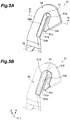
- part of the guide member 51 other than the yarn hooking portion 51a is embedded in the distal end portion 34 of the arm body member 31.
- an outer peripheral part 51d of the guide member 51 is embedded in a groove 34b formed on the side surface 34a of the distal end portion 34 on the inner peripheral side.
- the outer peripheral part 51d is an embedded portion embedded in the distal end portion 34.
- a side surface on the outer peripheral side and a pair of surfaces intersecting the direction ⁇ are covered by the groove 34b in a state of being in close contact with the groove 34b without a gap therebetween.
- an inner peripheral part 51e of the guide member 51 including the yarn hooking portion 51a is exposed from the distal end portion 34.
- the inner peripheral part 51e protrudes toward the curved-shape inner side more than the side surface 34a of the distal end portion 34 on the inner peripheral side does.
- outer periphery herein means a periphery of the curve bending in a hook-like shape on the outer side.
- the distal end 51c and its vicinity of the guide member 51 jut out toward the body portion 32 more than the distal end 34c of the distal end portion 34 does. With this configuration, the yarn Y to be traversed can be made less likely to come into contact with the distal end 34c of the distal end portion 34.
- the guide member 51 thus configured is integrally fixed to the distal end portion 34 of the arm body member 31.
- the guide member 51 is tucked into and engages with the arm body member 31 in the direction ⁇ , and is also tucked into and engages with the arm body member 31 in the direction intersecting the direction ⁇ .
- the guide member 51 is tucked into and engages with the arm body member 31 in all of the direction ⁇ , the direction ⁇ , and the direction ⁇ as depicted in FIG. 5A and FIG. 5B .
- the hardness of the guide member 51 is higher than the hardness of the arm body member 31.
- the hardness of material contained in the guide member 51 only needs to be equal to or higher than 120HV in Vickers hardness.
- Specific examples of the material contained in the guide member 51 include ceramics such as alumina and zirconia, siliconnitride, siliconcarbide, and high-hardness alloy materials such as a tungsten alloy, a nickel alloy, a chromium-molybdenum alloy, a nickel-chromium-molybdenum alloy, and a chromium alloy.
- the guide member 51 contains alumina.
- the guide member 51 containing alumina is prepared (step S1).
- This guide member 51 is formed in a hook-like shape by sintering using a muffle furnace, for example. On the guide member 51, grinding, for example, may be performed.
- the metallic material and the guide member 51 are placed in a die, and the die is closed.
- the metallic material in the die is hot molded and is then cooled to form the arm body member 31 (step S2).
- the metallic material and the guide member 51 are placed in the die so that at least part of the guide member 51 other than the yarn hooking portion 51a is embedded in the metallic material.
- the metallic material in a chip form or a pellet form may be placed in the die.
- the melting temperature of the metallic material is set lower, whereby dimensional accuracy and strength, for example, of the arm body member 31 can be improved.
- step S3 the arm body member 31 in which the guide member 51 is embedded is taken out of the die.
- step S4 the attached member 41 is attached to the arm body member 31 (step S4).
- step S4 with screws to be inserted into the through holes 33a, 33b, and 33c, the attached member 41 is fastened to the base end portion 33.
- the guide member 51 other than the yarn hooking portion 51a has the embedded portion (outer peripheral part 51d) embedded in the distal end portion 34 of the arm body member 31.
- the at least part of the guide member 51 other than the yarn hooking portion 51a enters and comes into close contact with the distal end portion 34 of the arm body member 31, and is tucked into the arm body member 31 so as not to detach. Consequently, the guide member 51 is integrally fixed, being firmly held on the arm body member 31 without adhesive applied therebetween so as not to detach.
- the guide member 51 can be reliably fixed to the arm body member 31.
- the traverse guide 30 can traverse the yarn Y for a long period of time.
- the guide member 51 and the distal end portion 34 integrally fixed to the guide member 51 each have a hook-like curved shape.
- the yarn hooking portion 51a is structured with portions including the side surface of the guide member 51 on the inner peripheral side, and is disposed on the curved-shape inner side than the side surface 34a of the distal end portion 34 on the inner peripheral side is.
- the guide member 51 is tucked into and engages with the arm body member 31 in the direction ⁇ , and also is tucked into and engages with the arm body member 31 in the direction intersecting the direction ⁇ . With this configuration, position error of the guide member 51 in the direction ⁇ and the direction intersecting the direction ⁇ can be prevented by the arm body member 31.
- the guide member 51 is fixed integrally with the arm body member 31 when the arm body member 31 is molded. In this case, without applying adhesive, the guide member 51 can be firmly fixed to the arm body member 31.
- the metallic material contained in the arm body member 31 is an aluminium alloy, a magnesium alloy, brass, a zinc alloy, a beryllium alloy, or zinc. This can reduce the weight of the traverse guide 30.
- the guide member 51 contains ceramics.
- the guide member 51 having high hardness can be prepared at low cost.
- the guide member 51 may contain a tungsten alloy, a nickel alloy, a chromium-molybdenum alloy, a nickel-chromium-molybdenum alloy, or a chromium alloy.
- the guide member 51 can contain a metallic material having high hardness.
- At least one of a diamond-like carbon film, a titanium nitride film, a titanium carbonitride film, a titanium aluminium nitride film, and an aluminium chromium nitride film may be provided. In this case, abrasion resistance of the guide member 51 improves.
- the guide member 51 and the distal end portion 34 may be provided to the body portion 32 on the distal end side in a state of being rotated 180° about the direction ⁇ from the state depicted in FIGS. 5A and 5B .
- the guide member 51 and the distal end portion 34 bending in hook-like shapes may be formed so that the opening on the curved-shape inner side is open to the distal end side of the arm body member 31, instead of being formed as depicted in FIGS. 5A and 5B in which the opening on the curved-shape inner side is open to the base end side of the arm body member 31.
- the guide member 51 may be integrally fixed to the distal end portion 34 by forming the groove 34b (see FIG. 6 ) of the distal end portion 34 so that the groove 34b is open to the distal end side, and embedding the outer peripheral part 51d of the guide member 51 along the groove 34b.
- an intermediate layer may be provided on a surface (e.g. , a side surface of the guide member 51 on the outer peripheral side) of the guide member 51 embedded in the arm body member 31.
- the traverse guide 30 may further include an intermediate layer provided on a surface of the guide member 51 embedded in the arm body member 31.
- the intermediate layer is a layer having excellent accessibility (wettability) to the arm body member 31 containing the metallic material.
- the intermediate layer is a metallization layer, for example.
- the metallization layer is provided on the surface of the guide member 51 by metallizing with high-melting point metal paste, active-metal plating, or noble-metal plating, for example.
- metallization layer By providing such a metallization layer on the surface, bondability between the arm body member 31 containing the metallic material and the guide member 51 containing ceramics can be improved.
- chemical bonding metal bonding
- the guide member 51 is firmly fixed to the arm body member 31.
- the metallization layer may be provided after the surface treatment film is formed, or may be provided before the surface treatment film is formed. In other words, the surface treatment film may be provided on the metallization layer, or may be provided between the surface of the arm body member 31 and the metallization layer.
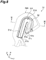
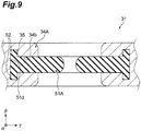
- a portion of a guide member 51A embedded in a distal end portion 34A is provided with a pair of protruding portions 52.
- the protruding portions 52 are provided extending along the outer peripheral part 51d of the guide member 51A.
- the protruding portions 52 protrude in the direction ⁇ from a pair of surfaces of the outer peripheral part 51d each on the outer peripheral side.
- This guide member 51A has a substantial T-shape cross section.
- recesses 35 in which the protruding portions 52 are embedded in a state of being in close contact therewith are formed.
- the recesses 35 have shapes corresponding to the protruding portions 52 of the guide member 51A.
- the recesses 35 are formed extending along the groove 34b.
- the recesses 35 are formed in a pair on the bottom side of the groove 34b so as to face each other in the direction ⁇ .
- the pair of the recesses 35 each are recessed on one side and the other side in the direction ⁇ .
- the guide member 51A is integrally fixed to the arm body member 31, being firmly held on the arm body member 31 without adhesive applied therebetween so as not to detach.
- the functional effect of enabling the guide member 51A to be reliably fixed to the arm body member 31 without applying adhesive can be obtained.
- the protruding portions 52 are engaged with the recesses 35 in the direction intersecting the direction ⁇ , whereby the guide member 51A can be reliably prevented from detaching. Because the protruding portions 52 are in close contact with the recesses 35, a backlash of the guide member 51 can be prevented.
- the protruding portions 52 do not necessarily have to be provided extending continuously along the outer peripheral part 51d of the guide member 51A, and may be provided extending intermittently, for example.
- the protruding portions 52 may be provided to the arm body member 31, and the recesses 35 may be formed in the guide member 51A.
- the above-described functional effect can be obtained. The essential thing is that either one of the portion of the guide member 51A embedded in the arm body member 31 and the arm body member 31 needs to be provided with the protruding portions 52, and the other needs to be provided with the recesses 35.
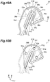
- part of the outer peripheral part 51g juts out toward the curved-shape outer side more than a distal end portion 34B does, and part of the inner peripheral part 51e juts out toward the curved-shape inner side more than the distal end portion 34B does.
- areas from the vicinity of the curved portion 51f to a distal end part in the outer peripheral part 51g of the guide member 51B are exposed from the distal end portion 34B.
- through holes 53a to 53c are formed each along the direction ⁇ .
- the shape of the through holes 53a to 53c in plan view is circular, but may be substantially rectangular, for example.
- the through holes 53a to 53c are formed in the guide member 51B at portions embedded in the distal end portion 34B.
- the through holes 53a to 53c are separated from each other.
- the through hole 53a is formed on the base end 51b side with respect to the curved portion 51f of the guide member 51B.
- the through hole 53b is formed near the curved portion 51f of the guide member 51B.
- the through hole 53c is formed on the distal end 51c side with respect to the curved portion 51f of the guide member 51B.
- the number of through holes formed in the guide member 51B may be one or two, or may be four or more.
- a plurality of through holes are formed in the guide member 51B, at least one thereof needs to be formed on the base end 51b side with respect to the curved portion 51f of the guide member 51B, and at least one of the others needs to be formed on the distal end 51c side with respect to the curved portion 51f of the guide member 51B.
- the distal end portion 34B includes a pair of plate-like portions 34d between which the guide member 51B is sandwiched along the direction ⁇ and bone portions 36a to 36c (first bone portion) extending along the direction ⁇ .
- the pair of the plate-like portions 34d are coupled to each other by the bone portions 36a to 36c.
- the number of bone portions provided to the distal end portion 34B is the same as the number of the through holes.
- the bone portion 36a is inserted into the through hole 53a and is in close contact with the inner surface of the through hole 53a.
- the bone portion 36b is inserted into the through hole 53b and is in close contact with the inner surface of the through hole 53b
- the bone portion 36c is inserted into the through hole 53c and is in close contact with the inner surface of the through hole 53c.
- the shapes of the bone portions 36a to 36c are the same as the shapes of the through holes 53a to 53c, respectively.
- the guide member 51B is integrally fixed to the arm body member 31, being firmly held on the arm body member 31 without adhesive applied therebetween so as not to detach.
- the functional effect of enabling the guide member 51B to be reliably fixed to the arm body member 31 without applying adhesive can be obtained.
- guide member 51B is engaged with the arm body member 31 in the direction intersecting the direction ⁇ by the through holes 53a to 53c and the bone portions 36a to 36c.
- the guide member 51B can be reliably prevented from detaching. Because the bone portions 36a to 36c are in close contact with the inner surfaces of the through holes 53a to 53c, respectively, a backlash of the guide member 51B can be prevented.
- the base end 51b of the guide member 51B is embedded in the distal end portion 34B of the arm body member 31.
- a gap or a level difference for example, formed between the base end 51b of the guide member 51B and the arm body member 31 can be bridged.
- protruding portions 37a to 37d may be provided to the distal end portion 34C.
- the protruding portions 37a to 37d each protrude toward the guide member 51C along the direction ⁇ .
- the distal end of the protruding portion 37a and the distal end of the protruding portion 37b face each other with a gap interposed therebetween in the direction ⁇ .
- the distal end of the protruding portion 37c and the distal end of the protruding portion 37d face each other with a gap interposed therebetween in the direction ⁇ .
- recesses 54a to 54d in which the protruding portions 37a to 37d are embedded, respectively, in a state of being in close contact therewith are formed.
- a plurality of dimples may be formed in the guide member 51C, and a plurality of protruding portions that are embedded in the respective dimples in a state of being in close contact therewith may be provided to the distal end portion 34C.
- the distal end of the protruding portion 37a and the distal end of the protruding portion 37b may be in contact with each other.
- the distal end of the protruding portion 37c and the distal end of the protruding portion 37d may be in contact with each other.
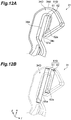
- a guide member 51D has a first member 61 and a second member 62.
- the first member 61 and the second member 62 are members having stick shapes each extending along the direction ⁇ .
- the first member 61 and the second member 62 are separated from each other in parallel.
- the length of the first member 61 along the direction ⁇ is longer than the length of the second member 62.
- the stick shape is also called a column shape.
- the first member 61 and the second member 62 may have a cylindrical column shape or may have a polygonal column shape.
- the first member 61 and the second member 62 of the thirdmodi f ication are members having cylindrical column shapes.
- Part of the first member 61 is embedded in a distal end portion 34D. Specifically, both end portions of the first member 61 are embedded in the distal end portion 34D. A portion of the first member 61 on the side opposite to the second member 62 side is embedded in the distal end portion 34D. In other words, both end portions of the first member 61 and the portion of the first member 61 on the side opposite to the second member 62 side are embedded portions embedded in the distal end portion 34D. In contrast, a portion of the first member 61 other than these portions is exposed from the distal end portion 34D.
- Part of the second member 62 is embedded in the distal end portion 34D. Specifically, both end portions of the second member 62 are embedded in the distal end portion 34D. A portion of the second member 62 on the side opposite to the first member 61 side is embedded in the distal end portion 34D. In other words, both end portions of the second member 62 and the portion of the second member 62 on the side opposite to the first member 61 side are embedded portions embedded in the distal end portion 34D. In contrast, a portion of the second member 62 other than these portions is exposed from the distal end portion 34D.
- the exposed portion of the first member 61 which is a portion of the first member 61 excluding both end portions and including a surface opposing to the second member 62, forms a yarn hooking portion 61a.
- the exposed portion of the second member 62 which is a portion of the second member 62 excluding both end portions and including a surface opposing to the first member 61, forms a yarn hooking portion 62a.
- the yarn hooking portions 61a and 62a have the same function as that of the yarn hooking portion 51a in the above-described embodiment. These yarn hooking portions 61a and 62a are disposed on the curved-shape inner side than the side surface 34a of the distal end portion 34D on the inner peripheral side.
- the distal end 34c of the distal end portion 34D protrudes toward a curved direction inner side (first member 61 side) in the direction ⁇ .
- the end portion of the second member 62 is securely embedded in the distal end portion 34D.
- the guide member 51D is integrally fixed to the arm body member 31, being firmly held thereon without adhesive applied therebetween so as not to detach.
- the functional effect of enabling the guide member 51D to be reliably fixed to the arm body member 31 without applying adhesive can be obtained.
- the guide member 51D can be easily formed. Because both ends of each of the first member 61 and the second member 62 are embedded in the distal end portion 34D, these both ends of each of the first member 61 and the second member 62 can reliably prevent the guide member 51D from detaching.
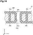
- a guide member 51E covers most part of the distal end portion 34E in the arm body member 31. Specifically, the guide member 51E covers at least the side surface 34a of the distal end portion 34E on the inner peripheral side and a pair of surfaces of the distal end portion 34E that intersect the direction ⁇ . In contrast, the side surface of the distal end portion 34E on the outer peripheral side is not covered by the guide member 51E.
- through holes 38a and 38b are formed along the direction ⁇ .
- the shape of the through holes 38a and 38b in plan view is circular, but may be substantially rectangular, for example.
- the through holes 38a and 38b are formed in the distal end portion 34E at portions covered by the guide member 51E, and are separated from each other.
- the through hole 38a is formed in the distal end portion 34E on the base end side with respect to a curved portion 34e.
- the through hole 38b is formed in the distal end portion 34E on the distal end side with respect to the curved portion 34e.
- the fourth modification when a plurality of through holes are formed in the distal end portion 34E, at least one of the through holes needs to be formed in the distal end portion 34E on the distal end side with respect to the curved portion 34e, and at least one of the other through holes needs to be formed in the distal end portion 34E on the base end side with respect to the curved portion 34e.
- the guide member 51E is provided with bone portions 55a and 55b (second bone portion) extending along the direction ⁇ .
- the number of bone portions provided to the guide member 51E is the same as the number of the through holes.
- the bone portion 55a is inserted into the through hole 38a and is in close contact with the inner surface of the through hole 38a.
- the bone portion 55b is inserted into the through hole 38b and is in close contact with the inner surface of the through hole 38b.
- the shapes of the bone portions 55a and 55b are the same as the shapes of the through holes 38a and 38b, respectively.
- the bone portions 55a and 55b are embedded portions embedded in the distal end portion 34E.
- the guide member 51E is integrally fixed to the arm body member 31, being firmly held thereon without a gap interposed therebetween and without adhesive applied therebetween so as not to detach.
- the guide member 51E is engaged with the arm body member 31 in the direction intersecting the direction ⁇ by the through holes 38a and 38b and the bone portions 55a and 55b.
- the guide member 51E can be reliably prevented from detaching. Because the bone portions 55a and 55b are in close contact with the inner surfaces of the through holes 38a and 38b, respectively, a backlash of the guide member 51E can be prevented.
- the base end 51b of the guide member 51 in the above-described embodiment may be embedded in the arm body member 31 as described in the second modification (the base end 51b may be included as an embedded portion).
- the yarn Y to be traversed can be prevented from being caught in a gap or a level difference, for example, formed between the base end 51b of the guide member 51 and the arm body member 31.
- the base end of the guide member 51E may be embedded in the arm body member 31 (the base end of the guide member 51E may be included as an embedded portion) .
- the arm body member 31 contains the metallic material, but the present disclosure is not limited to this.
- the arm body member 31 may contain metal oxide or resin.
- the arm body member 31 may be a component having the body portion 32 the length of which is very short in the direction ⁇ .
- the arm body member 31 may be a relatively small component that does not have the body portion 32 and in which the base end portion 33 and the distal end portion 34 are integrated.
- the arm body member 31 may be attached to a member configured to traverse, such as a belt.
- the essential thing is that the arm body member 31 only needs to be a member integrally fixing the guide member, and does not necessarily have to be a member in itself configured to traverse.
- a traverse guide includes: an arm body member having a distal end portion in a hook-like curved shape and containing a metallic material; and a guide member integrally fixed to the distal end portion of the arm body member and having a yarn hooking portion configured to hook a yarn.
- Hardness of the guide member is higher than hardness of the arm body member, and in at least part of the guide member other than the yarn hooking portion, an embedded portion to be embedded in the distal end portion is formed.
- the guide member may be fixed integrally with the arm body member when the arm body member is molded. In this case, without applying adhesive, the guide member can be firmly fixed to the arm body member.
- the traverse guide may include: an arm body member having a distal end portion in a hook-like curved shape and containing a metallic material; and a guide member integrally fixed to the distal end portion of the arm body member and having a yarn hooking portion configured to hook a yarn.
- an embedded portion to be embedded in the distal end portion may be formed. In this case, without applying adhesive, the guide member can be reliably fixed to the arm body member.
- the traverse guide may include: an arm body member having a distal endportion in a hook-like curved shape and containing a metallic material; and a guide member integrally fixed to the distal end portion of the arm body member and having a yarn hooking portion configured to hook a yarn.
- a through hole may be formed in the guide member, and the arm body member may have a first bone portion inserted into the through hole and being in close contact with an inner surface of the through hole. In this case, the through hole and the first bone portion can prevent the guide member from detaching. Because the first bone portion is in close contact with the inner surface of the through hole, a backlash of the guide member can be prevented.
- the traverse guide may include: an arm body member having a distal end port ion in a hook-like curved shape and containing a metallic material; and a guide member integrally fixed to the distal end portion of the arm body member and having a yarn hooking portion configured to hook a yarn.
- the guide member may be tucked into and engage with the arm body member along a traveling direction of the yarn, and may also be tucked into and engage with the arm body member along a direction intersecting the traveling direction. In this case, the arm body member canprevent position error of the guide member in the traveling direction and the direction intersecting the traveling direction.
- the traverse guide may include: an arm body member having a distal endportion in a hook-like curved shape and containing a metallic material; and a guide member integrally fixed to the distal end portion of the arm body member and having a yarn hooking portion configured to hook a yarn.
- the guide member may be provided so as to cover part of the arm body member, a through hole may be formed in the arm body member, and the guide member may have a second bone portion inserted into the through hole and being in close contact with an inner surface of the through hole. In this case, the through hole and the second bone portion can prevent the guide member from detaching. Because the second bone portion is in close contact with the inner surface of the through hole, a backlash of the guide member can be prevented.
- the traverse guide may include: an arm body member having a distal endportion in a hook-like curved shape and containing a metallic material; and a guide member integrally fixed to the distal end portion of the arm body member and having a yarn hooking portion configured to hook a yarn.
- the guide member may have a hook-like curved shape, and the yarn hooking portion may be structured with a portion including an inner peripheral surface of the guide member and may be disposed on a curved-shape inner side than an inner peripheral surface of the distal end portion is. In this case, the yarn to be traversed can be prevented from coming into contact with portions other than the yarn hooking portion.
Landscapes
- Guides For Winding Or Rewinding, Or Guides For Filamentary Materials (AREA)
- Winding Filamentary Materials (AREA)
Abstract
Description
- The present disclosure relates to a traverse guide, a yarn winding machine, and a method for producing the traverse guide.
- A yarn winding machine includes a traverse guide configured to move in a reciprocating rotational manner so as to traverse a yarn to be wound by a winding bobbin. For example, a distal end portion of an arm body member of a traverse guide described in
Japanese Unexamined Patent Publication No. 2013-63807 - The guide member described in
Japanese Unexamined Patent PublicationNo. 2013-63807 - In view of this, the present disclosure aims to provide a traverse guide, a yarn winding machine, and a method for producing the traverse guide in which a guide member can be reliably fixed to an arm body member without applying adhesive.
- A traverse guide according to one aspect of the present disclosure includes: an arm body member having a distal end portion in a hook-like curved shape and containing a metallic material; and a guide member integrally fixed to the distal end portion of the arm body member without adhesive applied therebetween and having a yarn hooking portion configured to hook a yarn. Hardness of the guide member is higher than hardness of the arm body member, and at least part of the guide member other than the yarn hooking portion has an embedded portion embedded in the distal end portion.
- In this traverse guide, at least part of the guide member other than the yarn hooking portion has the embedded portion embedded in the distal end portion of the arm body member. With this configuration, the guide member is integrally fixed to the distal end portion of the arm body member, being firmly held on the arm body member without adhesive applied therebetween so as not to detach. Thus, without applying adhesive, the guide member can be reliably fixed to the arm body member.
- In the traverse guide according to one aspect of the present disclosure, a through hole may be formed in the guide member, and the arm body member may have a first bone portion inserted into the through hole and being in close contact with an inner surface of the through hole. In this case, the through hole and the first bone portion can prevent the guide member from detaching. Because the first bone portion is in close contact with the inner surface of the through hole, a backlash of the guide member can be prevented.
- In the traverse guide according to one aspect of the present disclosure, the guide member may be tucked into and engage with the arm body member along a traveling direction of the yarn, and may also be tucked into and engage with the arm body member along a direction intersecting the traveling direction. In this case, the arm body member can prevent position error of the guide member in the traveling direction and the direction intersecting the traveling direction.
- In the traverse guide according to one aspect of the present disclosure, the guide member may be provided so as to cover part of the arm body member, a through hole may be formed in the arm body member, and the guide member may have a second bone portion inserted into the through hole and being in close contact with an inner surface of the throughhole. Inthiscase, the through hole and the second bone portion can prevent the guide member from detaching. Because the second bone portion is in close contact with the inner surface of the through hole, a backlash of the guide member can be prevented.
- In the traverse guide according to one aspect of the present disclosure, a protruding portion may be provided on either one of the at least part of the guide member embedded in the arm body member and the arm body member, and a recess with which the protruding portion is in close contact may be formed on the other one of the at least part of the guide member embedded in the arm body member and the arm bodymember. In this case, the protruding portion and the recess prevent the guide member from detaching. Because the protruding portion is in close contact with the recess, a backlash of the guide member can be prevented.
- In the traverse guide according to one aspect of the present disclosure, the protruding portion may protrude along the traveling direction of the yarn. In this case, in the direction intersecting the traveling direction of the yarn, by engaging the protruding portion with the recess, the guide member can be prevented from detaching.
- In the traverse guide according to one aspect of the present disclosure, the guide member may have a hook-like curved shape, and the yarn hooking portion may be structured with a portion including an inner peripheral surface of the guide member and may be disposed on a curved-shape inner side than an inner peripheral surface of the distal end portion is. In this case, the yarn to be traversed can be prevented from coming into contact with portions other than the yarn hooking portion.
- In the traverse guide according to one aspect of the present disclosure, a base end of the guide member may be embedded in the arm body member. In this case, a gap or a level difference, for example, formed between the base end of the guide member and the arm body member can be bridged. With this configuration, the yarn to be traversed can be prevented from being caught in the gap or the level difference, for example.
- In the traverse guide according to one aspect of the present disclosure, the guide member may have a first member and a second member that have stick shapes separated from each other in parallel, and both ends of the first member and both ends of the second member may be embedded in the arm body member. In this case, the first member and the second member of the guide member can be easily formed. In addition, both ends of the first member and the second member embedded in the arm body member can prevent the guide member from detaching.
- In the traverse guide according to one aspect of the present disclosure, the metallic material may be an aluminium alloy, a magnesium alloy, brass, a zinc alloy, a beryllium alloy, or zinc. This can reduce the weight of the traverse guide.
- In the traverse guide according to one aspect of the present disclosure, the guide member may contain ceramics. In this case, the guide member having high hardness can be prepared at low cost.
- The traverse guide according to one aspect of the present disclosure may further include an intermediate layer provided on a surface of the guide member embedded in the arm body member. In this case, the intermediate layer can improve bondability between the arm body member and the guide member.
- In the traverse guide according to one aspect of the present disclosure, the guide member may contain a tungsten alloy, a nickel alloy, a chromium-molybdenum alloy, a nickel-chromium-molybdenum alloy, or a chromium alloy. In this case, the guide member can contain a metallic material having high hardness.
- In the traverse guide according to one aspect of the present disclosure, on a surface of the guide member, at least one of a diamond-like carbon film, a titanium nitride film, a titanium carbonitride film, a titanium aluminium nitride film, and an aluminium chromium nitride film may be provided. In this case, abrasion resistance of the guide member improves.
- A yarn winding machine according to one aspect of the present disclosure includes: the traverse guide described in any one of the above paragraphs; a drive section configured to move the traverse guide in a reciprocating rotational manner; and a winding member configured to wind the yarn traversed by reciprocating rotational motion of the traverse guide onto a package.
- This yarn winding machine includes the above-described traverse guide, in which at least part of the guide member other than the yarn hooking portion is embedded in the arm body member. With this configuration, the guide member is integrally fixed to the arm body member, being firmly held on the arm body member without adhesive applied therebetween so as not to detach. Thus, without applying adhesive, the guide member can be reliably fixed to the arm body member.
- A method for producing a traverse guide according to one aspect of the present disclosure includes: a step of forming an arm body member by placing in a die a metallic material and a guide member having a hardness higher than that of the metallic material and having a yarn hooking portion configured to hook a yarn and by molding the metallic material in the die to form an arm body member. In the forming step, by embedding at least part of the guide member other than the yarn hooking portion in the metallic material, the arm body member is molded integrally with the guide member without adhesive applied therebetween.
- In the step in the method for producing a traverse guide, by embedding at least part of the guide member other than the yarn hooking portion in the metallic material, the arm body member is molded integrally with the guide member without adhesive applied therebetween. By the step, the guide member is integrally fixed to the arm body member, being firmly held on the arm body member without adhesive applied therebetween so as not to detach. Thus, without applying adhesive, the guide member can be reliably fixed to the arm body member.
- According to the present disclosure, the traverse guide, the yarn winding machine, and the method for producing the traverse guide can be provided in which the guide member can be fixed to the arm body member without applying adhesive.
-
-
FIG. 1 is a front view of an automatic winder including a winder unit according to one embodiment. -
FIG. 2 is a front view schematically illustrating the winder unit. -
FIG. 3 is a side view illustrating a traverse device. -
FIG. 4 is a perspective view illustrating the traverse guide. -
FIG. 5A is an enlarged perspective view illustrating a distal end portion of the traverse guide.FIG. 5B is an enlarged perspective view illustrating a guide member embedded in the distal end portion. -
FIG. 6 is a sectional view along line VI-VI inFIG. 5A . -
FIG. 7 is a flowchart illustrating one example of a method for producing the traverse guide. -
FIG. 8 is an enlarged perspective view illustrating a guide member embedded in a distal end portion according to a first modification. -
FIG. 9 is a sectional view along line IX-IX inFIG. 8 . -
FIG. 10A is an enlarged perspective view illustrating a distal end portion according to a second modification.FIG. 10B is an enlarged perspective view illustrating a guide member embedded in the distal end portion according to the second modification. -
FIG. 11A is a sectional view along line XI-XI inFIG. 10A .FIG. 11B is a sectional view of a distal end portion when bone portions in the second modification are changed to protruding portions. -
FIG. 12A is an enlarged perspective view illustrating a distal end portion according to a third modification.FIG. 12B is an enlarged perspective view illustrating a guide member embedded in the distal end portion according to the third modification. -
FIG. 13A is an enlarged perspective view illustrating a guide member according to a fourth modification.FIG. 13B is an enlarged perspective view illustrating a distal end portion covered by the guide member according to the fourth modification. -
FIG. 14 is a sectional view along line XIV-XIV inFIG. 13A . - An embodiment according to the present disclosure will now be described in detail with reference to the attached drawings. In the following description, like elements or elements having like functions are designated by like numerals, and duplicate description is omitted.
- Referring to
FIG. 1 , an overall configuration of anautomatic winder 1 including a winder unit (yarn winding machine) 2 of the present embodiment will be described. In the following description, the terms "upstream" and "downstream" mean upstream and downstream in a traveling direction of a yarn Y during yarn winding. - As depicted in
FIG. 1 , theautomatic winder 1 includes a plurality ofwinder units 2 disposed in parallel and amachine control device 4. Themachine control device 4 controls (manages) operation of the entireautomatic winder 1. Theautomatic winder 1 may further include an automatic doffing device (not depicted). - As depicted in
FIG. 2 , eachwinder unit 2 includes a winding unitmain body 3 and aunit controller 17 as main components. - The
unit controller 17 includes a central processing unit (CPU), a random access memory (RAM), a read only memory (ROM), an I/O port, and a communication port. The ROM stores therein a program for controlling the respective components of thewinder unit 2. The I/O port and the communication port are connected to respective sections (described later in detail) and themachine control device 4 included in thewinder unit 2 are connected. The I/O port and the communication port are configured to enable communication of control information, for example, therethrough. With this configuration, theunit controller 17 can control operation of the respective sections included in thewinder unit 2. - The winding unit
main body 3 includes ayarn supplying section 5, a yarn-unwinding assistingdevice 7, atension applying device 9, ayarn monitor 11, asplicer device 13, and a winding section (winding member) 15 in a yarn traveling path between ayarn supplying bobbin 6 and acontact roller 22. - In a lower portion of the
winder unit 2, theyarn supplying section 5 is provided. Theyarn supplying section 5 is configured to be able to hold theyarn supplying bobbin 6 conveyed by a bobbin conveying system (not depicted) in a predetermined position. - The yarn-unwinding assisting
device 7 assists unwinding of the yarn Y from theyarn supplying bobbin 6 by lowering aregulation member 8 covering a core tube of theyarn supplying bobbin 6 in conj unction with unwinding of the yarn Y from theyarn supplying bobbin 6. Theregulation member 8 comes into contact with a balloon of the yarn Y that is formed in an upper portion of theyarn supplying bobbin 6 by rotation and centrifugal force of the yarn Y unwound from theyarn supplying bobbin 6, and controls the balloon of the yarn Y to an appropriate size, thereby assisting the unwinding of the yarn Y. Near theregulation member 8, a sensor (not depicted) for detecting a chase portion of theyarn supplying bobbin 6 is provided. When this sensor detects descent of the chase portion, the yarn-unwinding assistingdevice 7 follows the descent of the chase portion to lower theregulation member 8 by an air cylinder (not depicted), for example. - The
tension applying device 9 applies a predetermined tension to the traveling yarn Y. As thetension applying device 9, for example, a gate-type device in which movable comb teeth are disposed with respect to fixed comb teeth can be used. By causing the yarn Y to pass through between the comb teeth meshing with each other while causing the yarn Y to bend, resistance can be applied to the traveling yarn Y to apply an appropriate tension thereto. As thetension applying device 9, in addition to the above-described gate-type device, for example, a disk-type device can be used. - The yarn monitor 11 includes a sensor (not depicted) for detecting an abnormal part (yarn defect) of the yarn Y. Near the
yarn monitor 11, acutter 12 configured to cut the yarn Y immediately after theyarn monitor 11 has detected a yarn defect is provided. - When the
yarn monitor 11 has detected a yarn defect and cuts the yarn, or when the yarn being unwound from theyarn supplying bobbin 6 breaks, for example, thesplicer device 13 splices the lower yarn on theyarn supplying bobbin 6 side and the upper yarn on the side of a windingbobbin 14. As the splicer device configured to splice the upper yarn and the lower yarn, a mechanical knotter or a device using fluid such as compressed air, for example, can be used. - Below the
splicer device 13, a lower-yarn catching member 16 configured to catch the lower yarn to guide the lower yarn to thesplicer device 13 is provided. Above thesplicer device 13, an upperyarn catching member 18 configured to catch the upper yarn to guide the upper yarn to thesplicer device 13 is provided. - The winding
section 15 includes acradle 20 configured to support the windingbobbin 14 around which the yarn Y is wound and thecontact roller 22 configured to come into contact with the circumferential surface of the windingbobbin 14 and being rotatable. The windingsection 15 includes a rotational driving source (not depicted) configured to rotationally drive the windingbobbin 14 supported by thecradle 20. By rotationally driving the windingbobbin 14, the yarn Y can be wound around the circumference of the windingbobbin 14. The windingbobbin 14 around which the yarn Y has been wound in this manner is called a package P. - The
winder unit 2 includes an arm-type traverse device 24 configured to traverse the yarn Y to be wound around the windingbobbin 14 near thecradle 20. As depicted inFIG. 3 , thetraverse device 24 includes a traverse driving motor (driving section) 26 and atraverse guide 30. - The
traverse driving motor 26 is a driving source configured to move thetraverse guide 30 in a reciprocating rotational manner. Thetraverse driving motor 26 is configured with a servo motor, for example. Thetraverse driving motor 26 has arotational drive shaft 28 connected to thetraverse guide 30 as an output shaft. Thetraverse guide 30 is fixed to therotational drive shaft 28 in a relatively non-rotatable manner. As depicted inFIG. 3 , in a state in which thetraverse guide 30 is fixed to therotational drive shaft 28, the longitudinal direction of thetraverse guide 30 is substantially orthogonal to therotational drive shaft 28. - The rotor of the
traverse driving motor 26 repeats forward and reverse rotations, whereby thetraverse guide 30 moves in a reciprocating rotational manner. In a guide member 51 (described later in detail) attached to thetraverse guide 30, the yarn Y is caught. Accordingly, this yarn Y reciprocates in the winding width direction (lateral direction inFIG. 2 ) of the package P in conjunction with the motion of thetraverse guide 30. By rotating the windingbobbin 14 while the yarn Y is being guided by theguide member 51, the yarn Y is wound around the windingbobbin 14 while being traversed, whereby the package P of a predetermined shape can be formed. - The following describes the
traverse guide 30 in detail. As depicted inFIG. 4 , thetraverse guide 30 includes anarm body member 31 and an attachedmember 41 attached to thearm body member 31. The following description is made assuming that the longitudinal direction of thetraverse guide 30 is a "direction α", the direction along the traveling direction of the yarn Y orthogonal to the direction α is a "direction β", and the crosswise direction of thetraverse guide 30 orthogonal to the direction α and to the direction β is a "direction γ". The direction intersecting the direction P is any direction including the direction α and the direction γ. - The
arm body member 31 has abody portion 32, abase end portion 33 provided to thebody portion 32 on the base end side in the direction α, and adistal end portion 34 provided to thebody portion 32 on the distal end side in the direction α. Thearm body member 31 contains a metallic material. Thearm body member 31 of the present embodiment ismoldedby die casting, thixomolding, or inj ectionmolding, for example, using the metallic material. Thearm body member 31 is molded integrally with theguide member 51 described later without adhesive applied therebetween. The metallic material herein is a material containing metal or an alloy. Examples of the metallic material contained in thearm body member 31 include an aluminium alloy, a magnesium alloy, brass, a zinc alloy, a beryllium alloy, and zinc. - The
body portion 32 has a shape of a plate that tapers down from thebase end portion 33 toward thedistal end portion 34. Thebase end portion 33 is a portion to which the attachedmember 41 is attached. On thebase end portion 33, throughholes holes member 41 through the throughholes member 41 is fastened to thebase end portion 33. Into the throughhole 33d, the rotational drive shaft 28 (seeFIG. 3 ) is inserted. - The attached
member 41 contains aluminium, for example. The attachedmember 41 is formed by machining, for example. In the attachedmember 41, anattachment hole 42 into which the rotational drive shaft 28 (seeFIG. 3 ) is inserted is formed. Thetraverse guide 30 is attached to the rotational drive shaft 28 (seeFIG. 3 ) through theattachment hole 42. - Referring to
FIG. 4 ,FIG. 5A ,FIG. 5B , andFIG. 6 , the following describes thedistal end portion 34 and theguide member 51 that is fixed integrally with thedistal end portion 34 in detail. - As depicted in
FIG. 5A , thedistal end portion 34 has a hook-like curved shape. Specifically, thedistal end portion 34 extends straight from the base end side along the direction α and is then curved, and the distal end thereof extends so as to face thebase end portion 33. Thedistal end portion 34 bends in a hook-like shape to form a substantial J-shape in plan view. - The
guide member 51 is a portion that comes into contact with the yarn Y in thetraverse guide 30. Theguide member 51 has ayarn hooking portion 51a configured to hook the yarn Y. As depicted inFIG. 5B , similarly to thedistal end portion 34, theguide member 51 has a hook-like curved shape having a substantial J-shape in plan view. Specifically, theguide member 51 extends straight from thebase end 51b thereof along the direction β and is then curved at acurved portion 51f, and thedistal end 51c thereof extends so as to face thebase end portion 33. In theguide member 51, thebase end 51b is positioned closer to thebody portion 32 than thedistal end 51c is. Theguide member 51 may be surface treated. In this case, on theguide member 51, a surface treatment film is provided. This surface treatment film includes at least one of a diamond-like carbon film (DLC film), a titanium nitride film (TiN film), a titanium carbonitride film (TiCN film), a titanium aluminium nitride film (TiAlN film), and an aluminium chromium nitride film (AlCrN film). - The
yarn hooking portion 51a is structured with portions including a side surface of theguide member 51 on the inner peripheral side. Theyarn hooking portion 51a is disposed on a curved-shape inner side than aside surface 34a of thedistal end portion 34 on the inner peripheral side is. Theyarn hooking portion 51a is provided along the shape of theguide member 51, and bends in a hook-like shape to form a substantial J-shape in plan view. The yarn Y (seeFIG. 3 ) traversed by thetraverse device 24 slidingly travels while being in contact with theyarn hooking portion 51a. The term "inner periphery" herein means a periphery of the curve bending in a hook-like shape on the inner side. The term "curved-shape inner side" means the inner side in the curved shape. - As depicted in
FIG. 5B andFIG. 6 , part of theguide member 51 other than theyarn hooking portion 51a is embedded in thedistal end portion 34 of thearm body member 31. Specifically, in agroove 34b formed on theside surface 34a of thedistal end portion 34 on the inner peripheral side, an outerperipheral part 51d of theguide member 51 is embedded. In other words, the outerperipheral part 51d is an embedded portion embedded in thedistal end portion 34. In the outerperipheral part 51d, a side surface on the outer peripheral side and a pair of surfaces intersecting the direction β are covered by thegroove 34b in a state of being in close contact with thegroove 34b without a gap therebetween. In contrast, an innerperipheral part 51e of theguide member 51 including theyarn hooking portion 51a is exposed from thedistal end portion 34. The innerperipheral part 51e protrudes toward the curved-shape inner side more than theside surface 34a of thedistal end portion 34 on the inner peripheral side does. The term "outer periphery" herein means a periphery of the curve bending in a hook-like shape on the outer side. - The
distal end 51c and its vicinity of theguide member 51 jut out toward thebody portion 32 more than thedistal end 34c of thedistal end portion 34 does. With this configuration, the yarn Y to be traversed can be made less likely to come into contact with thedistal end 34c of thedistal end portion 34. - The
guide member 51 thus configured is integrally fixed to thedistal end portion 34 of thearm body member 31. Theguide member 51 is tucked into and engages with thearm body member 31 in the direction β, and is also tucked into and engages with thearm body member 31 in the direction intersecting the direction β. In other words, theguide member 51 is tucked into and engages with thearm body member 31 in all of the direction α, the direction β, and the direction γ as depicted inFIG. 5A and FIG. 5B . - As described above, the hardness of the
guide member 51 is higher than the hardness of thearm body member 31. For example, the hardness of material contained in theguide member 51 only needs to be equal to or higher than 120HV in Vickers hardness. Specific examples of the material contained in theguide member 51 include ceramics such as alumina and zirconia, siliconnitride, siliconcarbide, and high-hardness alloy materials such as a tungsten alloy, a nickel alloy, a chromium-molybdenum alloy, a nickel-chromium-molybdenum alloy, and a chromium alloy. In the present embodiment, theguide member 51 contains alumina. - The following describes one example of a method for producing the
traverse guide 30 with reference toFIG. 7 . As depicted inFIG. 7 , theguide member 51 containing alumina is prepared (step S1). Thisguide member 51 is formed in a hook-like shape by sintering using a muffle furnace, for example. On theguide member 51, grinding, for example, may be performed. - Subsequently, the metallic material and the
guide member 51 are placed in a die, and the die is closed. The metallic material in the die is hot molded and is then cooled to form the arm body member 31 (step S2). At step S2, the metallic material and theguide member 51 are placed in the die so that at least part of theguide member 51 other than theyarn hooking portion 51a is embedded in the metallic material. When thearm body member 31 is molded from the metallic material in the die, this placement allows thearm body member 31 and theguide member 51 to be integrated without adhesive applied therebetween. In other words, theguide member 51 is fixed integrally with thearm body member 31 when thearm body member 31 is molded. - At step S2, when the
arm body member 31 is formed by injection molding, the metallic material in a chip form or a pellet form may be placed in the die. When thearm body member 31 containing the metallic material is formed by injection molding, the melting temperature of the metallic material is set lower, whereby dimensional accuracy and strength, for example, of thearm body member 31 can be improved. - Subsequently, the
arm body member 31 in which theguide member 51 is embedded is taken out of the die (step S3). After grinding or other treatment is performed on thearm body member 31 if necessary, the attachedmember 41 is attached to the arm body member 31 (step S4). At step S4, with screws to be inserted into the throughholes member 41 is fastened to thebase end portion 33. Through the above steps, thetraverse guide 30 is produced. - It should be noted that directly identifying the structure of the
traverse guide 30 may be impossible or unrealistic because theguide member 51 is integrally fixed when thearm body member 31 is molded as described above. In other words, there are circumstances in which directly identifying all of thetraverse guide 30 based on the structure or characteristics thereof is impossible or unrealistic. - In the
traverse guide 30, thewinder unit 2 including thetraverse guide 30, and the method for producing thetraverse guide 30 described above, at least part of theguide member 51 other than theyarn hooking portion 51a has the embedded portion (outerperipheral part 51d) embedded in thedistal end portion 34 of thearm body member 31. With this configuration, the at least part of theguide member 51 other than theyarn hooking portion 51a enters and comes into close contact with thedistal end portion 34 of thearm body member 31, and is tucked into thearm body member 31 so as not to detach. Consequently, theguide member 51 is integrally fixed, being firmly held on thearm body member 31 without adhesive applied therebetween so as not to detach. Thus, without applying adhesive, theguide member 51 can be reliably fixed to thearm body member 31. - Even if conditions for using the
traverse guide 30 have changed, strength of fixing thearm body member 31 to theguide member 51 is less likely to decrease than the case that a guide member is fixed to an arm body member by applying adhesive. Because the hardness of theguide member 51 is higher than the hardness of thearm body member 31, abrasion resistance of theyarn hooking portion 51a can be improved. Thus, in thewinder unit 2 including the above-describedtraverse guide 30, thetraverse guide 30 can traverse the yarn Y for a long period of time. - The
guide member 51 and thedistal end portion 34 integrally fixed to theguide member 51 each have a hook-like curved shape. Theyarn hooking portion 51a is structured with portions including the side surface of theguide member 51 on the inner peripheral side, and is disposed on the curved-shape inner side than theside surface 34a of thedistal end portion 34 on the inner peripheral side is. With this configuration, the yarn Y to be traversed can be reliably hooked on theyarn hooking portion 51a, and the yarn Y can be prevented from coming into contact with portions other than theyarn hooking portion 51a. - The
guide member 51 is tucked into and engages with thearm body member 31 in the direction β, and also is tucked into and engages with thearm body member 31 in the direction intersecting the direction β. With this configuration, position error of theguide member 51 in the direction β and the direction intersecting the direction β can be prevented by thearm body member 31. - The
guide member 51 is fixed integrally with thearm body member 31 when thearm body member 31 is molded. In this case, without applying adhesive, theguide member 51 can be firmly fixed to thearm body member 31. - The metallic material contained in the
arm body member 31 is an aluminium alloy, a magnesium alloy, brass, a zinc alloy, a beryllium alloy, or zinc. This can reduce the weight of thetraverse guide 30. - The
guide member 51 contains ceramics. In this case, theguide member 51 having high hardness can be prepared at low cost. Herein, instead of ceramics, theguide member 51 may contain a tungsten alloy, a nickel alloy, a chromium-molybdenum alloy, a nickel-chromium-molybdenum alloy, or a chromium alloy. In this case, theguide member 51 can contain a metallic material having high hardness. - On a surface of the
guide member 51, at least one of a diamond-like carbon film, a titanium nitride film, a titanium carbonitride film, a titanium aluminium nitride film, and an aluminium chromium nitride film may be provided. In this case, abrasion resistance of theguide member 51 improves. - In the
traverse guide 30 according to the above-described embodiment, theguide member 51 and thedistal end portion 34 may be provided to thebody portion 32 on the distal end side in a state of being rotated 180° about the direction β from the state depicted inFIGS. 5A and 5B . In other words, theguide member 51 and thedistal end portion 34 bending in hook-like shapes may be formed so that the opening on the curved-shape inner side is open to the distal end side of thearm body member 31, instead of being formed as depicted inFIGS. 5A and 5B in which the opening on the curved-shape inner side is open to the base end side of thearm body member 31. Specifically, theguide member 51 may be integrally fixed to thedistal end portion 34 by forming thegroove 34b (seeFIG. 6 ) of thedistal end portion 34 so that thegroove 34b is open to the distal end side, and embedding the outerperipheral part 51d of theguide member 51 along thegroove 34b. - In the method for producing the
traverse guide 30 according to the above-described embodiment, when the material contained in theguide member 51 is ceramics, before step S2, an intermediate layer may be provided on a surface (e.g. , a side surface of theguide member 51 on the outer peripheral side) of theguide member 51 embedded in thearm body member 31. In other words, thetraverse guide 30 may further include an intermediate layer provided on a surface of theguide member 51 embedded in thearm body member 31. The intermediate layer is a layer having excellent accessibility (wettability) to thearm body member 31 containing the metallic material. The intermediate layer is a metallization layer, for example. The metallization layer is provided on the surface of theguide member 51 by metallizing with high-melting point metal paste, active-metal plating, or noble-metal plating, for example. By providing such a metallization layer on the surface, bondability between thearm body member 31 containing the metallic material and theguide member 51 containing ceramics can be improved. In addition, by chemical bonding (metal bonding) between the metallic material of thearm body member 31 and the metallization layer, without applying adhesive, theguide member 51 is firmly fixed to thearm body member 31. If theguide member 51 is surface treated, the metallization layer may be provided after the surface treatment film is formed, or may be provided before the surface treatment film is formed. In other words, the surface treatment film may be provided on the metallization layer, or may be provided between the surface of thearm body member 31 and the metallization layer. - Hereinafter, first to fourth modifications of the above-described embodiment will be described. In the description of the first to fourth modifications, points different from those in the above-described embodiment will be mainly described.
- The following describes the first modification. In the first modification, as depicted in
FIG. 8 andFIG. 9 , a portion of aguide member 51A embedded in adistal end portion 34A is provided with a pair of protrudingportions 52. The protrudingportions 52 are provided extending along the outerperipheral part 51d of theguide member 51A. The protrudingportions 52 protrude in the direction β from a pair of surfaces of the outerperipheral part 51d each on the outer peripheral side. Thisguide member 51A has a substantial T-shape cross section. - In the
arm body member 31, recesses 35 in which the protrudingportions 52 are embedded in a state of being in close contact therewith are formed. Therecesses 35 have shapes corresponding to the protrudingportions 52 of theguide member 51A. Therecesses 35 are formed extending along thegroove 34b. Therecesses 35 are formed in a pair on the bottom side of thegroove 34b so as to face each other in the direction β. The pair of therecesses 35 each are recessed on one side and the other side in the direction β. - In also the first modification described above, the
guide member 51A is integrally fixed to thearm body member 31, being firmly held on thearm body member 31 without adhesive applied therebetween so as not to detach. Thus, the functional effect of enabling theguide member 51A to be reliably fixed to thearm body member 31 without applying adhesive can be obtained. Furthermore, in the first modification, the protrudingportions 52 are engaged with therecesses 35 in the direction intersecting the direction β, whereby theguide member 51A can be reliably prevented from detaching. Because the protrudingportions 52 are in close contact with therecesses 35, a backlash of theguide member 51 can be prevented. - In the above-described first modification, only either one of the pair of the protruding
portions 52 may be provided. The protrudingportions 52 do not necessarily have to be provided extending continuously along the outerperipheral part 51d of theguide member 51A, and may be provided extending intermittently, for example. The protrudingportions 52 may be provided to thearm body member 31, and therecesses 35 may be formed in theguide member 51A. In also these cases, the above-described functional effect can be obtained. The essential thing is that either one of the portion of theguide member 51A embedded in thearm body member 31 and thearm body member 31 needs to be provided with the protrudingportions 52, and the other needs to be provided with therecesses 35. - The following describes the second modification. In the second modification, as depicted in
FIG. 10A, FIG. 10B , andFIG. 11A , in aguide member 51B, part of the outerperipheral part 51g juts out toward the curved-shape outer side more than adistal end portion 34B does, and part of the innerperipheral part 51e juts out toward the curved-shape inner side more than thedistal end portion 34B does. Specifically, areas from the vicinity of thecurved portion 51f to a distal end part in the outerperipheral part 51g of theguide member 51B are exposed from thedistal end portion 34B. In the same manner, areas from thedistal end 51c to the vicinity of thebase end 51b in the innerperipheral part 51e of theguide member 51B are exposed from thedistal end portion 34B. In contrast, areas other than the above-described exposed areas in theguide member 51B are embedded in thedistal end portion 34B. In other words, areas other than the exposed areas in theguide member 51B are embedded portions embedded in thedistal end portion 34B. - In the
guide member 51B, throughholes 53a to 53c are formed each along the direction β. The shape of the throughholes 53a to 53c in plan view is circular, but may be substantially rectangular, for example. The throughholes 53a to 53c are formed in theguide member 51B at portions embedded in thedistal end portion 34B. The throughholes 53a to 53c are separated from each other. As depicted inFIG. 10B , the throughhole 53a is formed on thebase end 51b side with respect to thecurved portion 51f of theguide member 51B. The throughhole 53b is formed near thecurved portion 51f of theguide member 51B. The throughhole 53c is formed on thedistal end 51c side with respect to thecurved portion 51f of theguide member 51B. The number of through holes formed in theguide member 51B may be one or two, or may be four or more. When a plurality of through holes are formed in theguide member 51B, at least one thereof needs to be formed on thebase end 51b side with respect to thecurved portion 51f of theguide member 51B, and at least one of the others needs to be formed on thedistal end 51c side with respect to thecurved portion 51f of theguide member 51B. - The
distal end portion 34B includes a pair of plate-like portions 34d between which theguide member 51B is sandwiched along the direction β andbone portions 36a to 36c (first bone portion) extending along the direction β. The pair of the plate-like portions 34d are coupled to each other by thebone portions 36a to 36c. The number of bone portions provided to thedistal end portion 34B is the same as the number of the through holes. Thebone portion 36a is inserted into the throughhole 53a and is in close contact with the inner surface of the throughhole 53a. In the same manner, thebone portion 36b is inserted into the throughhole 53b and is in close contact with the inner surface of the throughhole 53b, and thebone portion 36c is inserted into the throughhole 53c and is in close contact with the inner surface of the throughhole 53c. Thus, the shapes of thebone portions 36a to 36c are the same as the shapes of the throughholes 53a to 53c, respectively. - In also the second modification described above, the
guide member 51B is integrally fixed to thearm body member 31, being firmly held on thearm body member 31 without adhesive applied therebetween so as not to detach. Thus, the functional effect of enabling theguide member 51B to be reliably fixed to thearm body member 31 without applying adhesive can be obtained. - Furthermore, in the second modification,
guide member 51B is engaged with thearm body member 31 in the direction intersecting the direction β by the throughholes 53a to 53c and thebone portions 36a to 36c. Thus, theguide member 51B can be reliably prevented from detaching. Because thebone portions 36a to 36c are in close contact with the inner surfaces of the throughholes 53a to 53c, respectively, a backlash of theguide member 51B can be prevented. - In the second modification, as depicted in
FIG. 10B , thebase end 51b of theguide member 51B is embedded in thedistal end portion 34B of thearm body member 31. In this case, a gap or a level difference, for example, formed between thebase end 51b of theguide member 51B and thearm body member 31 can be bridged. With this configuration, the yarn Y to be traversed can be prevented from being caught in the gap or the level difference, for example. - Alternatively, as depicted in
FIG. 11B , instead of thebone portions 36a to 36c (seeFIG. 11A ), protrudingportions 37a to 37d may be provided to thedistal end portion 34C. The protrudingportions 37a to 37d each protrude toward theguide member 51C along the direction β. The distal end of the protrudingportion 37a and the distal end of the protrudingportion 37b face each other with a gap interposed therebetween in the direction β. The distal end of the protrudingportion 37c and the distal end of the protrudingportion 37d face each other with a gap interposed therebetween in the direction β. In theguide member 51C, recesses 54a to 54d in which the protrudingportions 37a to 37d are embedded, respectively, in a state of being in close contact therewith are formed. - Alternatively, for example, a plurality of dimples (recesses) may be formed in the
guide member 51C, and a plurality of protruding portions that are embedded in the respective dimples in a state of being in close contact therewith may be provided to thedistal end portion 34C. Furthermore, for example, the distal end of the protrudingportion 37a and the distal end of the protrudingportion 37b may be in contact with each other. In the same manner, the distal end of the protrudingportion 37c and the distal end of the protrudingportion 37d may be in contact with each other. - The following describes the third modification. In the third modification, as depicted in
FIG. 12A and FIG. 12B , aguide member 51D has afirst member 61 and asecond member 62. Thefirst member 61 and thesecond member 62 are members having stick shapes each extending along the direction α. Thefirst member 61 and thesecond member 62 are separated from each other in parallel. The length of thefirst member 61 along the direction α is longer than the length of thesecond member 62. The stick shape is also called a column shape. Thefirst member 61 and thesecond member 62 may have a cylindrical column shape or may have a polygonal column shape. Thefirst member 61 and thesecond member 62 of the thirdmodi f ication are members having cylindrical column shapes. - Part of the
first member 61 is embedded in adistal end portion 34D. Specifically, both end portions of thefirst member 61 are embedded in thedistal end portion 34D. A portion of thefirst member 61 on the side opposite to thesecond member 62 side is embedded in thedistal end portion 34D. In other words, both end portions of thefirst member 61 and the portion of thefirst member 61 on the side opposite to thesecond member 62 side are embedded portions embedded in thedistal end portion 34D. In contrast, a portion of thefirst member 61 other than these portions is exposed from thedistal end portion 34D. - Part of the
second member 62 is embedded in thedistal end portion 34D. Specifically, both end portions of thesecond member 62 are embedded in thedistal end portion 34D. A portion of thesecond member 62 on the side opposite to thefirst member 61 side is embedded in thedistal end portion 34D. In other words, both end portions of thesecond member 62 and the portion of thesecond member 62 on the side opposite to thefirst member 61 side are embedded portions embedded in thedistal end portion 34D. In contrast, a portion of thesecond member 62 other than these portions is exposed from thedistal end portion 34D. - The exposed portion of the
first member 61, which is a portion of thefirst member 61 excluding both end portions and including a surface opposing to thesecond member 62, forms ayarn hooking portion 61a. The exposed portion of thesecond member 62, which is a portion of thesecond member 62 excluding both end portions and including a surface opposing to thefirst member 61, forms ayarn hooking portion 62a. Theyarn hooking portions yarn hooking portion 51a in the above-described embodiment. Theseyarn hooking portions side surface 34a of thedistal end portion 34D on the inner peripheral side. - Herein, the
distal end 34c of thedistal end portion 34D protrudes toward a curved direction inner side (first member 61 side) in the direction γ. With this configuration, the end portion of thesecond member 62 is securely embedded in thedistal end portion 34D. - In also the third modification described above, the
guide member 51D is integrally fixed to thearm body member 31, being firmly held thereon without adhesive applied therebetween so as not to detach. Thus, the functional effect of enabling theguide member 51D to be reliably fixed to thearm body member 31 without applying adhesive can be obtained. Furthermore, in the third modification, because thefirst member 61 and thesecond member 62 are simple members having stick shapes, theguide member 51D can be easily formed. Because both ends of each of thefirst member 61 and thesecond member 62 are embedded in thedistal end portion 34D, these both ends of each of thefirst member 61 and thesecond member 62 can reliably prevent theguide member 51D from detaching. - The following describes the fourth modification. In the fourth modification, as depicted in
FIG. 13A, FIG. 13B , andFIG. 14 , aguide member 51E covers most part of thedistal end portion 34E in thearm body member 31. Specifically, theguide member 51E covers at least theside surface 34a of thedistal end portion 34E on the inner peripheral side and a pair of surfaces of thedistal end portion 34E that intersect the direction β. In contrast, the side surface of thedistal end portion 34E on the outer peripheral side is not covered by theguide member 51E. - In the
distal end portion 34E, throughholes holes holes distal end portion 34E at portions covered by theguide member 51E, and are separated from each other. As depicted inFIG. 13B , the throughhole 38a is formed in thedistal end portion 34E on the base end side with respect to acurved portion 34e. The throughhole 38b is formed in thedistal end portion 34E on the distal end side with respect to thecurved portion 34e. In the fourth modification, when a plurality of through holes are formed in thedistal end portion 34E, at least one of the through holes needs to be formed in thedistal end portion 34E on the distal end side with respect to thecurved portion 34e, and at least one of the other through holes needs to be formed in thedistal end portion 34E on the base end side with respect to thecurved portion 34e. - The
guide member 51E is provided withbone portions guide member 51E is the same as the number of the through holes. Thebone portion 55a is inserted into the throughhole 38a and is in close contact with the inner surface of the throughhole 38a. In the same manner, thebone portion 55b is inserted into the throughhole 38b and is in close contact with the inner surface of the throughhole 38b. Thus, the shapes of thebone portions holes bone portions distal end portion 34E. - In also the fourth modification described above, the
guide member 51E is integrally fixed to thearm body member 31, being firmly held thereon without a gap interposed therebetween and without adhesive applied therebetween so as not to detach. Thus, the functional effect of enabling theguide member 51E to be firmly fixed to thearm body member 31 without applying adhesive can be obtained. Furthermore, in the fourth modification, theguide member 51E is engaged with thearm body member 31 in the direction intersecting the direction β by the throughholes bone portions guide member 51E can be reliably prevented from detaching. Because thebone portions holes guide member 51E can be prevented. - In the foregoing, the embodiment according to the present disclosure and the modifications thereof have been described, but the present disclosure is not limited to the above-described embodiment and the above-described modifications. The present disclosure may be modified within a scope not altering the gist described in each claim. The above-described embodiment and the above-described modifications may be used in combination as appropriate.
- For example, the
base end 51b of theguide member 51 in the above-described embodiment may be embedded in thearm body member 31 as described in the second modification (thebase end 51b may be included as an embedded portion). In this case, also in the above-described embodiment, in the same manner as in the second modification, the yarn Y to be traversed can be prevented from being caught in a gap or a level difference, for example, formed between thebase end 51b of theguide member 51 and thearm body member 31. In the same manner, also in the fourth modification, the base end of theguide member 51E may be embedded in the arm body member 31 (the base end of theguide member 51E may be included as an embedded portion) . - In the above-described embodiment and the above-described modifications, the
arm body member 31 contains the metallic material, but the present disclosure is not limited to this. For example, thearm body member 31 may contain metal oxide or resin. Thearm body member 31 may be a component having thebody portion 32 the length of which is very short in the direction α. Alternatively, thearm body member 31 may be a relatively small component that does not have thebody portion 32 and in which thebase end portion 33 and thedistal end portion 34 are integrated. In this case, thearm body member 31 may be attached to a member configured to traverse, such as a belt. The essential thing is that thearm body member 31 only needs to be a member integrally fixing the guide member, and does not necessarily have to be a member in itself configured to traverse. - At least some parts of the embodiment and the modifications described above may be optionally used in combination.
- A traverse guide includes: an arm body member having a distal end portion in a hook-like curved shape and containing a metallic material; and a guide member integrally fixed to the distal end portion of the arm body member and having a yarn hooking portion configured to hook a yarn. Hardness of the guide member is higher than hardness of the arm body member, and in at least part of the guide member other than the yarn hooking portion, an embedded portion to be embedded in the distal end portion is formed.
- In the traverse guide, the guide member may be fixed integrally with the arm body member when the arm body member is molded. In this case, without applying adhesive, the guide member can be firmly fixed to the arm body member.
- The traverse guide may include: an arm body member having a distal end portion in a hook-like curved shape and containing a metallic material; and a guide member integrally fixed to the distal end portion of the arm body member and having a yarn hooking portion configured to hook a yarn. In at least part of the guide member other than the yarn hooking portion, an embedded portion to be embedded in the distal end portion may be formed. In this case, without applying adhesive, the guide member can be reliably fixed to the arm body member.
- The traverse guide may include: an arm body member having a distal endportion in a hook-like curved shape and containing a metallic material; and a guide member integrally fixed to the distal end portion of the arm body member and having a yarn hooking portion configured to hook a yarn. A through hole may be formed in the guide member, and the arm body member may have a first bone portion inserted into the through hole and being in close contact with an inner surface of the through hole. In this case, the through hole and the first bone portion can prevent the guide member from detaching. Because the first bone portion is in close contact with the inner surface of the through hole, a backlash of the guide member can be prevented.
- The traverse guide may include: an arm body member having a distal end port ion in a hook-like curved shape and containing a metallic material; and a guide member integrally fixed to the distal end portion of the arm body member and having a yarn hooking portion configured to hook a yarn. The guide member may be tucked into and engage with the arm body member along a traveling direction of the yarn, and may also be tucked into and engage with the arm body member along a direction intersecting the traveling direction. In this case, the arm body member canprevent position error of the guide member in the traveling direction and the direction intersecting the traveling direction.
- The traverse guide may include: an arm body member having a distal endportion in a hook-like curved shape and containing a metallic material; and a guide member integrally fixed to the distal end portion of the arm body member and having a yarn hooking portion configured to hook a yarn. The guide member may be provided so as to cover part of the arm body member, a through hole may be formed in the arm body member, and the guide member may have a second bone portion inserted into the through hole and being in close contact with an inner surface of the through hole. In this case, the through hole and the second bone portion can prevent the guide member from detaching. Because the second bone portion is in close contact with the inner surface of the through hole, a backlash of the guide member can be prevented.
- The traverse guide may include: an arm body member having a distal endportion in a hook-like curved shape and containing a metallic material; and a guide member integrally fixed to the distal end portion of the arm body member and having a yarn hooking portion configured to hook a yarn. The guide member may have a hook-like curved shape, and the yarn hooking portion may be structured with a portion including an inner peripheral surface of the guide member and may be disposed on a curved-shape inner side than an inner peripheral surface of the distal end portion is. In this case, the yarn to be traversed can be prevented from coming into contact with portions other than the yarn hooking portion.
Claims (16)
- A traverse guide comprising:an arm body member (31) having a distal end portion (34, 34A to 34E) in a hook-like curved shape and containing a metallic material; anda guide member (51, 51A to 51E) integrally fixed to the distal end portion of the arm body member without adhesive applied therebetween and having a yarn hooking portion (51a, 61a, 62a) configured to hook a yarn (Y), whereinhardness of the guide member is higher than hardness of the arm body member, and
at least part of the guide member other than the yarn hooking portion has an embedded portion (51B, 51d, 55a, 55b, 61, 62) embedded in the distal end portion. - The traverse guide according to claim 1, wherein
a through hole (53a to 53c) is formed in the guide member, and
the arm body member has a first bone portion (36a to 36c) inserted into the through hole and being in close contact with an inner surface of the through hole. - The traverse guide according to claim 1 or 2, wherein the guide member is tucked into and engage with the arm body member along a traveling direction of the yarn, and is also tucked into and engage with the arm body member along a direction intersecting the traveling direction.
- The traverse guide according to claim 1, wherein
the guide member is provided so as to cover part of the arm body member,
a through hole (38a, 38b) is formed in the arm body member, and the guide member has a second bone portion (55a, 55b) inserted into the through hole and being in close contact with an inner surface of the through hole. - The traverse guide according to any one of claims 1 to 4, wherein
a protruding portion (37a to 37d, 52) is provided on either one of the at least part of the guide member embedded in the arm body member and the arm body member, and
a recess (54a to 54d, 35) with which the protruding portion is in close contact is formed on the other one of the at least part of the guide member embedded in the arm body member and the arm body member. - The traverse guide according to claim 5, wherein the protruding portion protrudes along the traveling direction of the yarn.
- The traverse guide according to any one of claims 1 to 6, wherein
the guide member has a hook-like curved shape, and
the yarn hooking portion is structured with a portion including an inner peripheral surface of the guide member and is disposed on a curved-shape inner side than an inner peripheral surface of the distal end portion is. - The traverse guide according to claim 7, wherein a base end of the guide member is embedded in the arm body member.
- The traverse guide according to claim 1, wherein
the guide member has a first member (61) and a second member (62) that have stick shapes separated from each other in parallel, and
both ends of the first member and both ends of the second member are embedded in the arm body member. - The traverse guide according to any one of claims 1 to 9, wherein the metallic material is an aluminium alloy, a magnesium alloy, brass, a zinc alloy, a beryllium alloy, or zinc.
- The traverse guide according to any one of claims 1 to 10, wherein the guide member contains ceramics.
- The traverse guide according to claim 11, further comprising an intermediate layer provided on a surface of the guide member embedded in the arm body member.
- The traverse guide according to any one of claims 1 to 10, wherein the guide member contains a tungsten alloy, a nickel alloy, a chromium-molybdenum alloy, a nickel-chromium-molybdenum alloy, or a chromium alloy.
- The traverse guide according to any one of claims 1 to 13 , wherein on a surface of the guide member, at least one of a diamond-like carbon film, a titanium nitride film, a titanium carbonitride film, a titanium aluminium nitride film, and an aluminium chromium nitride film is provided.
- A yarn winding machine comprising:the traverse guide (30) as claimed in any one of claims 1 to 14;a drive section (26) configured to move the traverse guide in a reciprocating rotational manner; anda winding section (15) configured to wind the yarn traversed by reciprocating rotational motion of the traverse guide onto a package (P).
- A method for producing a traverse guide, comprising:a step of forming an arm body member by placing in a die a metallic material and a guide member having a hardness higher than that of the metallic material and having a yarn hooking portion configured to hook a yarn and by molding the metallic material in the die, whereinin the forming step, by embedding at least part of the guide member other than the yarn hooking portion in the metallic material, the arm body member is molded integrally with the guide member without adhesive applied therebetween.
Applications Claiming Priority (1)
| Application Number | Priority Date | Filing Date | Title |
|---|---|---|---|
| JP2015219385A JP2017088301A (en) | 2015-11-09 | 2015-11-09 | Traverse guide, yarn winding machine, and method for manufacturing traverse guide |
Publications (1)
| Publication Number | Publication Date |
|---|---|
| EP3165488A1 true EP3165488A1 (en) | 2017-05-10 |
Family
ID=57218725
Family Applications (1)
| Application Number | Title | Priority Date | Filing Date |
|---|---|---|---|
| EP16195738.6A Withdrawn EP3165488A1 (en) | 2015-11-09 | 2016-10-26 | Traverse guide, yarn winding machine, and method for producing traverse guide |
Country Status (3)
| Country | Link |
|---|---|
| EP (1) | EP3165488A1 (en) |
| JP (1) | JP2017088301A (en) |
| CN (1) | CN106904486A (en) |
Cited By (1)
| Publication number | Priority date | Publication date | Assignee | Title |
|---|---|---|---|---|
| CN112520501A (en) * | 2021-02-03 | 2021-03-19 | 苏州天沐乐纺织有限公司 | Extension arm on creel |
Families Citing this family (1)
| Publication number | Priority date | Publication date | Assignee | Title |
|---|---|---|---|---|
| CN110923420A (en) * | 2019-12-17 | 2020-03-27 | 常熟市恒丰机械制造有限公司 | Production process of yarn guide |
Citations (3)
| Publication number | Priority date | Publication date | Assignee | Title |
|---|---|---|---|---|
| US6505791B1 (en) * | 1998-06-12 | 2003-01-14 | Maschinenfabrik Rieter Ag | Thread traversing device |
| EP2196423A2 (en) * | 2008-12-10 | 2010-06-16 | Murata Machinery, Ltd. | Traverse arm and yarn winding machine including the same |
| JP2013063807A (en) | 2011-09-15 | 2013-04-11 | Murata Machinery Ltd | Traverse guide, winding unit, and yarn winder |
-
2015
- 2015-11-09 JP JP2015219385A patent/JP2017088301A/en active Pending
-
2016
- 2016-10-25 CN CN201610937176.9A patent/CN106904486A/en active Pending
- 2016-10-26 EP EP16195738.6A patent/EP3165488A1/en not_active Withdrawn
Patent Citations (3)
| Publication number | Priority date | Publication date | Assignee | Title |
|---|---|---|---|---|
| US6505791B1 (en) * | 1998-06-12 | 2003-01-14 | Maschinenfabrik Rieter Ag | Thread traversing device |
| EP2196423A2 (en) * | 2008-12-10 | 2010-06-16 | Murata Machinery, Ltd. | Traverse arm and yarn winding machine including the same |
| JP2013063807A (en) | 2011-09-15 | 2013-04-11 | Murata Machinery Ltd | Traverse guide, winding unit, and yarn winder |
Cited By (1)
| Publication number | Priority date | Publication date | Assignee | Title |
|---|---|---|---|---|
| CN112520501A (en) * | 2021-02-03 | 2021-03-19 | 苏州天沐乐纺织有限公司 | Extension arm on creel |
Also Published As
| Publication number | Publication date |
|---|---|
| CN106904486A (en) | 2017-06-30 |
| JP2017088301A (en) | 2017-05-25 |
Similar Documents
| Publication | Publication Date | Title |
|---|---|---|
| RU2608019C2 (en) | Positive feeder device for feeding metal wires at constant tension | |
| US11472109B2 (en) | Three-dimensional printing apparatus | |
| EP2712830B1 (en) | Traverse arm and yarn winding machine including the same | |
| US8020309B2 (en) | Circularity measuring apparatus | |
| JP5514229B2 (en) | Wire saw device and method of operating a wire saw device | |
| RU2603509C2 (en) | System and method for supply of metal wires with constant tension | |
| JP5288836B2 (en) | Machine tool with chip disposal function | |
| JP2018512973A5 (en) | ||
| EP2570377B1 (en) | Traverse guide, winding unit, and winding machine | |
| JP6117458B1 (en) | Cutting device and cutting blade | |
| WO2017179132A1 (en) | Automatic sizing cutting device | |
| US9409737B2 (en) | Endless clip-strip feed splicer | |
| EP2907645A1 (en) | Injection unit | |
| JP2005119880A (en) | Tape winding device | |
| RS65791B1 (en) | Method and yarn feeder system for optimising yarn feed to a textile machine operating highly discontinuously or with alternating motion | |
| JP2017088301A (en) | Traverse guide, yarn winding machine, and method for manufacturing traverse guide | |
| EP3042872B1 (en) | Yarn winding machine and method for manufacturing a package | |
| TW201826896A (en) | Electronic component removal device | |
| JP5930301B2 (en) | Finger-shaped yarn guide | |
| JP4987621B2 (en) | Yarn winding device | |
| EP3689803B1 (en) | Thread winding device | |
| JPH09233775A (en) | Motor rotor manufacturing equipment | |
| EP4286312A1 (en) | Yarn joining device | |
| EP2982631A1 (en) | Traverse arm and yarn winding machine | |
| JPH11207593A (en) | Polishing equipment |
Legal Events
| Date | Code | Title | Description |
|---|---|---|---|
| PUAI | Public reference made under article 153(3) epc to a published international application that has entered the european phase |
Free format text: ORIGINAL CODE: 0009012 |
|
| AK | Designated contracting states |
Kind code of ref document: A1 Designated state(s): AL AT BE BG CH CY CZ DE DK EE ES FI FR GB GR HR HU IE IS IT LI LT LU LV MC MK MT NL NO PL PT RO RS SE SI SK SM TR |
|
| AX | Request for extension of the european patent |
Extension state: BA ME |
|
| 17P | Request for examination filed |
Effective date: 20170823 |
|
| RBV | Designated contracting states (corrected) |
Designated state(s): AL AT BE BG CH CY CZ DE DK EE ES FI FR GB GR HR HU IE IS IT LI LT LU LV MC MK MT NL NO PL PT RO RS SE SI SK SM TR |
|
| 17Q | First examination report despatched |
Effective date: 20180503 |
|
| STAA | Information on the status of an ep patent application or granted ep patent |
Free format text: STATUS: THE APPLICATION HAS BEEN WITHDRAWN |
|
| 18W | Application withdrawn |
Effective date: 20180604 |