EP3165433B1 - Rangierantrieb für einen anhänger - Google Patents
Rangierantrieb für einen anhänger Download PDFInfo
- Publication number
- EP3165433B1 EP3165433B1 EP16196325.1A EP16196325A EP3165433B1 EP 3165433 B1 EP3165433 B1 EP 3165433B1 EP 16196325 A EP16196325 A EP 16196325A EP 3165433 B1 EP3165433 B1 EP 3165433B1
- Authority
- EP
- European Patent Office
- Prior art keywords
- gear
- drive
- manoeuvring
- pinion
- reduction
- Prior art date
- Legal status (The legal status is an assumption and is not a legal conclusion. Google has not performed a legal analysis and makes no representation as to the accuracy of the status listed.)
- Not-in-force
Links
- 230000005540 biological transmission Effects 0.000 claims description 10
- 230000000694 effects Effects 0.000 description 1
- 230000008092 positive effect Effects 0.000 description 1
Images




Classifications
-
- B—PERFORMING OPERATIONS; TRANSPORTING
- B62—LAND VEHICLES FOR TRAVELLING OTHERWISE THAN ON RAILS
- B62D—MOTOR VEHICLES; TRAILERS
- B62D59/00—Trailers with driven ground wheels or the like
- B62D59/04—Trailers with driven ground wheels or the like driven from propulsion unit on trailer
Definitions
- the invention relates to a Rangierantrieb for a trailer, with an electric motor, a drive roller and a gear that couples the electric motor with the drive roller.
- the document EP 2 669 155 A2 discloses a generic Rangierantrieb.
- the trailer may be, for example, a caravan, a boat trailer, a horse trailer, a market trailer or the like. This is usually pulled by a tractor. In a caravan is usually a car as a tractor. In order to bring the trailer to its final position, for example at a campsite, it is usually uncoupled from the tractor and then placed in the final position.
- the Rangierantrieb can be used, which is an auxiliary drive with which the trailer can then be moved when it is not coupled to the tractor.
- the drive roller engages the running surface of the wheel to which the corresponding shunting drive is assigned.
- the electric motor is then operated depending on the desired direction of travel of the trailer in one direction or the other, so that via the gear, the drive roller and from this the wheel of the trailer is rotated.
- a worm gear As a transmission between the drive roller and the electric motor, a worm gear can be used.
- the advantage of a worm gear is that it is self-locking. Thus, even if the trailer is maneuvered on an inclined ground by means of the shunting drive, it remains on its own despite the downhill force when the electric motor is switched off; There is no separate braking device necessary.
- the disadvantage of a worm gear is quite low efficiency.
- spur or bevel gear are known. These are characterized by a much higher efficiency. However, can not achieve self-locking with a spur gear, so that a braking device is required.
- the object of the invention is to improve the known Rangierantriebe to the effect that results in a higher efficiency in a small space.
- the invention provides a shunting drive of the type mentioned that the transmission is a self-locking hypoid gear. Due to the crossed arrangement of the input and the output shaft, there are advantages in terms of the necessary space, since the drive motor can be optimally arranged on Rangierantrieb and results in a low interference contour. In addition, a hypoid gear can achieve a high efficiency, which is on the order of 80%. At the same time, the toothing can be designed so that the transmission is self-locking. Thus it can be dispensed with a braking device. Due to the much higher efficiency compared to a worm gear, a smaller electric motor can be used with the same drive power of the Rangierantriebs.
- the offset of the axis of rotation of the pinion of the hypoid gear relative to the axis of rotation of the ring gear of the hypoid gear is preferably in the order of 20% to 80% of the radius of the toothing of the ring gear.
- the selected offset can be used with regard to the available standing space and the characteristics of the transmission are suitably chosen.
- a functional and shape-optimized envelope of the Rangierantriebs can be obtained.
- a pinion shaft is provided, on which the pinion is arranged and which is mounted on both sides of the pinion.
- the pinion is mounted on one side. This can be advantageous in terms of a compact housing of the transmission.
- the reduction ratio between the pinion and the ring gear can be selected in a wide range depending on the respective requirements.
- values above 8: 1 have been found, in particular above 12: 1, 16: 1 and 20: 1.
- a further reduction gear between the electric motor and the drive roller having a reduction ratio in the range of 5: 1 of 25: 1.
- the additional reduction gear makes it possible to use a high-speed electric motor with speeds in the range of more than 6,000 rpm up to 10,000 rpm.
- the reduction gear can be single-stage or multi-stage.
- the further reduction gear can be designed as a spur gear or as a planetary gear.
- the sun gear of the planetary gear is coupled to the ring gear, the ring gear is fixed and the planet carrier is coupled to a drive roller shaft. This results in a particularly compact design.
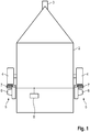
- FIG. 1 schematically a trailer 2 is shown, for example, a caravan.
- the trailer 2 has a drawbar 3, with which it can be coupled to a train carriage, and two wheels. 4
- Each of the wheels 4 is associated with a shunting drive 5, which has an electric motor 6 and a drive roller 7. To power the electric motor 6, a battery 8 is provided.
- Each shunting drive 5 can be adjusted by means of a pressure mechanism not shown here between a starting position in which the drive roller 7 is at a distance from the running surface of the wheel 4, and an activated position in which the drive roller 7 is pressed against the running surface of the wheel 4 is that a rotation of the drive roller 7 is transmitted to the wheel 4.
- FIG. 2 a Rangierantrieb according to a first embodiment is shown.
- the electric motor 6 has a motor shaft 12 which is coupled to a pinion 14.
- the pinion 14 engages in a ring gear 16 a.
- the axis of rotation of the pinion 14 is offset relative to the axis of rotation of the ring gear 16 by an offset V.
- the axes of rotation do not intersect so; they are skewed.
- the offset V is on the order of 20 to 80% of the radius of the ring gear 16th
- a further reduction gear is arranged between the gear formed by the pinion 14 and the ring gear 16 and the drive roller 7, a further reduction gear is arranged.
- This is designed here as a planetary gear with a sun gear 20, a ring gear 22 and a plurality of planetary gears 24 which are arranged on a planet carrier 26.
- the sun gear 20 is fixedly connected to the ring gear 16.
- the ring gear 22 is rotatably mounted within the housing 28 of the Rangierantriebs 5.
- the planet carrier 26 is coupled to a drive roller shaft 30, on which the drive roller 7 is arranged rotationally fixed.
- gear formed by the pinion 14 and the ring gear 16 is a hypoid gear.
- the reduction ratio of the hypoid gear may be of the order of 8: 1 to 12: 1.
- the reduction ratio of the planetary gear can be in the same range.
- the teeth of the hypoid gear is designed to be self-locking.
- the pinion 14 is mounted by means of two bearings 50 in the housing 28 on one side.
- the bearings 50 are located on one and the same side of the pinion, namely, away from the drive roller shaft 30.
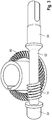
- FIG. 3 a variant embodiment is shown, in which the pinion 14 is arranged on a pinion shaft 52 which is mounted on both sides of the pinion 14.
- bearing portions 54 are provided. This is possible when the offset V is chosen so large that the pinion shaft 52 does not collide with the output side of the ring gear 16.
- Suitable values for the reduction ratio of the hypoid gear are in the range of 12: 1 to 25: 1. Due to the self-locking of the gearbox, it is possible to dispense with an engine brake. Despite the self-locking efficiency of the order of 80% can be achieved.
- the cone angle ⁇ (see FIG. 2a ) can be very small in such a transmission. In extreme cases, it is close to 0 or even 0. Accordingly, the toothing of the pinion 14 has a cone angle which is very close to 0 or 0.
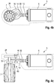
- FIG. 4 a second embodiment is shown.
- the same reference numerals are used, and reference is made to the above explanations in this respect.
- the difference between the first and the second embodiment is that no planetary gear is used as the second reduction gear, but a spur gear 60, which is designed here in one stage.
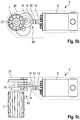
- FIG. 5 a third embodiment is shown.
- the same reference numerals are used, and reference is made to the above explanations in this respect.
- the second reduction gear 60 is made in two stages.
- the gear formed by the pinion 14 and the ring gear 16 is a self-locking hypoid gear.
Landscapes
- Engineering & Computer Science (AREA)
- Chemical & Material Sciences (AREA)
- Combustion & Propulsion (AREA)
- Transportation (AREA)
- Mechanical Engineering (AREA)
- Connection Of Motors, Electrical Generators, Mechanical Devices, And The Like (AREA)
- Gear Transmission (AREA)
- Retarders (AREA)
Description
- Die Erfindung betrifft einen Rangierantrieb für einen Anhänger, mit einem Elektromotor, einer Antriebsrolle und einem Getriebe, das den Elektromotor mit der Antriebsrolle koppelt. Das Dokument
EP 2 669 155 A2 offenbart einen gattungsgemäßen Rangierantrieb. Bei dem Anhänger kann es sich beispielsweise um einen Wohnwagen, einen Bootsanhänger, einen Pferdeanhänger, einen Marktanhänger oder ähnliches handeln. Dieser wird üblicherweise von einer Zugmaschine gezogen. Bei einem Wohnwagen dient meist ein Pkw als Zugmaschine. Um den Anhänger in seine endgültige Position zu bringen, beispielsweise auf einem Campingplatz, wird er üblicherweise von der Zugmaschine abgekoppelt und dann in die endgültige Position rangiert. Hierfür kann der Rangierantrieb verwendet werden, der ein Hilfsantrieb ist, mit dem der Anhänger dann bewegt werden kann, wenn er nicht an die Zugmaschine angekoppelt ist. - Wenn sich der Rangierantrieb in einem betriebsbereiten Zustand befindet, greift die Antriebsrolle an der Lauffläche des Rades an, dem der entsprechende Rangierantrieb zugeordnet ist. Der Elektromotor wird dann je nach gewünschter Fahrtrichtung des Anhängers in der einen oder der anderen Richtung betrieben, sodass über das Getriebe die Antriebsrolle und von dieser das Rad des Anhängers gedreht wird.
- Als Getriebe zwischen der Antriebsrolle und dem Elektromotor kann ein Schneckenradgetriebe verwendet werden. Der Vorteil eines Schneckenradgetriebes besteht darin, dass es selbsthemmend ist. Somit bleibt der Anhänger, auch wenn er mittels des Rangierantriebs auf geneigtem Untergrund rangiert wird, trotz der Hangabtriebskraft von alleine stehen, wenn der Elektromotor ausgeschaltet wird; es ist keine separate Bremseinrichtung notwendig. Der Nachteil eines Schneckenradgetriebes besteht allerdings im recht geringen Wirkungsgrad.
- Als Getriebe zwischen der Antriebsrolle und dem Elektromotor sind auch Stirnrad- oder Kegelradgetriebe bekannt. Diese zeichnen sich durch einen deutlich höheren Wirkungsgrad aus. Allerdings lässt sich mit einem Stirnradgetriebe keine Selbsthemmung erzielen, sodass eine Bremseinrichtung erforderlich ist.
- Die Aufgabe der Erfindung besteht darin, die bekannten Rangierantriebe dahingehend zu verbessern, dass sich ein höherer Wirkungsgrad bei kleinem Bauraum ergibt.
- Zur Lösung dieser Aufgabe ist erfindungsgemäß bei einem Rangierantrieb der eingangs genannten Art vorgesehen, dass das Getriebe ein selbsthemmendes Hypoidgetriebe ist. Durch die gekreuzte Anordnung der Eingangs- und der Ausgangswelle ergeben sich Vorteile hinsichtlich des notwendigen Bauraums, da der Antriebsmotor optimal am Rangierantrieb angeordnet werden kann und sich eine geringe Störkontur ergibt. Mit einem Hypoidgetriebe lässt sich außerdem ein hoher Wirkungsgrad erzielen, der in der Größenordnung von 80% liegt. Gleichzeitig lässt sich die Verzahnung so ausgestalten, dass das Getriebe selbsthemmend ist. Somit kann auf eine Bremseinrichtung verzichtet werden. Aufgrund des im Vergleich zu einem Schneckenradgetriebe sehr viel höheren Wirkungsgrades kann bei gleicher Antriebsleistung des Rangierantriebs ein kleinerer Elektromotor verwendet werden. Dies verringert das Gewicht und die Kosten, was die tendenziell etwas höheren Kosten für die Hypoidverzahnung mehr als kompensiert. Als weitere Vorteile ergeben sich unter anderem, dass kleiner dimensionierte Kabel für die Stromversorgung des Antriebsmotors verwendet können. Weitere positive Effekte sind, dass aufgrund des verbesserten Wirkungsgrades die Steuerung schwächer dimensioniert werden kann und eine Batterie mit geringerer Kapazität ausreichend ist.
- Weitere Spezialformen des selbsthemmenden Hypoidgetriebe sind auch bekannt als Spiroidgetriebe / SRH-Getriebe.
- Der Versatz der Drehachse des Ritzels des Hypoidgetriebes relativ zur Drehachse des Tellerrades des Hypoidgetriebes beträgt vorzugsweise in der Größenordnung von 20% bis 80% des Radius der Verzahnung des Tellerrades. Der jeweils gewählte Versatz kann dabei im Hinblick auf den zur Verfügung stehenden Bauraum und die Eigenschaften des Getriebes geeignet gewählt werden. Insbesondere kann eine funktions- und gestaltoptimierte Hüllkurve des Rangierantriebs erhalten werden.
- Gemäß einer Ausgestaltung der Erfindung ist eine Ritzelwelle vorgesehen, auf der das Ritzel angeordnet ist und die beiderseits des Ritzels gelagert ist. Durch die Lagerung des Ritzels auf beiden Seiten werden Kippmomente vermieden.
- Gemäß einer alternativen Ausgestaltung ist vorgesehen, dass das Ritzel einseitig gelagert ist. Dies kann im Hinblick auf ein kompaktes Gehäuse des Getriebes vorteilhaft sein.
- Die Untersetzung zwischen dem Ritzel und dem Tellerrad kann in einem großen Bereich abhängig von den jeweiligen Anforderungen gewählt werden. Vorteilhaft haben sich Werte oberhalb von 8:1 herausgestellt, insbesondere oberhalb von 12:1, 16:1 und 20:1.
- Vorzugsweise ist ein weiteres Untersetzungsgetriebe zwischen Elektromotor und Antriebsrolle vorhanden, die ein Untersetzungsverhältnis im Bereich von 5:1 von 25:1 hat. Das weitere Untersetzungsgetriebe ermöglicht es, einen schnelllaufenden Elektromotor mit Drehzahlen im Bereich von über 6.000 U/min bis zu 10.000 U/min zu verwenden.
- Abhängig vom jeweiligen Anwendungsfall kann das Untersetzungsgetriebe einstufig oder mehrstufig sein. Dabei kann je nach konkretem Anwendungsfall das weitere Untersetzungsgetriebe als Stirnradgetriebe oder auch als Planetenradgetriebe ausgeführt sein.
- Gemäß einer bevorzugten Ausführungsform der Erfindung ist das Sonnenrad des Planetenradgetriebes mit dem Tellerrad gekoppelt, das Hohlrad ist feststehend und der Planetenradträger ist mit einer Antriebsrollenwelle gekoppelt. Hierdurch ergibt sich ein besonders kompakter Aufbau.
- Die Erfindung wird nachfolgend anhand verschiedener Ausführungsformen beschrieben, die in den beigefügten Zeichnungen dargestellt sind. In diesen zeigen:
-
Figur 1 schematisch einen Anhänger mit Rangierantrieb; - die
Figuren 2a bis 2d in einer schematischen Schnittansicht, einer perspektivischen Ansicht, einer Seitenansicht und einer Draufsicht einen Rangierantrieb gemäß einer ersten Ausführungsform; -
Figur 3 in einer perspektivischen Ansicht eine Variante des Getriebes, das beim Rangierantrieb gemäß der ersten Ausführungsform verwendet werden kann; -
Figur 4 in einer perspektivischen Ansicht, einer Seitenansicht und einer Draufsicht einen Rangierantrieb gemäß einer zweiten Ausführungsform; und -
Figur 5 in Ansichten entsprechend denjenigen vonFigur 4 einen Rangierantrieb gemäß einer dritten Ausführungsform. - In
Figur 1 ist schematisch ein Anhänger 2 gezeigt, beispielsweise ein Wohnwagen. Der Anhänger 2 weist eine Deichsel 3 auf, mit der er an einen Zugwagen angekoppelt werden kann, sowie zwei Räder 4. - Jedem der Räder 4 ist ein Rangierantrieb 5 zugeordnet, der einen Elektromotor 6 und eine Antriebsrolle 7 aufweist. Zur Energieversorgung des Elektromotors 6 ist eine Batterie 8 vorgesehen.
- Jeder Rangierantrieb 5 kann mittels eines hier nicht gezeigten Andruckmechanismus zwischen einer Ausgangsposition, in der die Antriebsrolle 7 sich im Abstand von der Lauffläche des Rades 4 befindet, und einer aktivierten Stellung verstellt werden, in der die Antriebsrolle 7 gegen die Lauffläche des Rades 4 so gepresst wird, dass eine Drehung der Antriebsrolle 7 auf das Rad 4 übertragen wird.
- In
Figur 2 ist ein Rangierantrieb gemäß einer ersten Ausführungsform gezeigt. - Der Elektromotor 6 weist eine Motorwelle 12 auf, die mit einem Ritzel 14 gekoppelt ist. Das Ritzel 14 greift in ein Tellerrad 16 ein.
- Wie in
Figur 2c zu sehen ist, ist die Drehachse des Ritzels 14 relativ zur Drehachse des Tellerrades 16 um einen Versatz V versetzt. Die Drehachsen schneiden sich also nicht; sie sind windschief. - Der Versatz V liegt in der Größenordnung von 20 bis 80% des Radius des Tellerrades 16.
- Zwischen dem vom Ritzel 14 und dem Tellerrad 16 gebildeten Getriebe und der Antriebsrolle 7 ist ein weiteres Untersetzungsgetriebe angeordnet. Dieses ist hier als Planetenradgetriebe mit einem Sonnenrad 20, einem Hohlrad 22 und mehreren Planetenrädern 24 ausgeführt, die auf einem Planetenradträger 26 angeordnet sind.
- Das Sonnenrad 20 ist fest mit dem Tellerrad 16 verbunden. Das Hohlrad 22 ist drehfest innerhalb des Gehäuses 28 des Rangierantriebs 5 angebracht. Der Planetenradträger 26 ist mit einer Antriebsrollenwelle 30 gekoppelt, auf der die Antriebsrolle 7 drehfest angeordnet ist.
- Bei dem vom Ritzel 14 und dem Tellerrad 16 gebildeten Getriebe ist ein Hypoidgetriebe.
- Das Untersetzungsverhältnis des Hypoidgetriebes kann in der Größenordnung von 8:1 bis 12:1 liegen.
- Das Untersetzungsverhältnis des Planetenradgetriebes kann im selben Bereich liegen.
- Um zu gewährleisten, dass sich der mit dem Rangierantrieb 5 versehene Anhänger nicht unbeabsichtigt in Bewegung setzt, wenn er auf einem geneigten, abfallenden Untergrund rangiert wird, ist die Verzahnung des Hypoidgetriebes selbsthemmend ausgelegt.
- Bei der in
Figur 2 gezeigten Ausführungsform ist das Ritzel 14 mittels zweier Wälzlager 50 im Gehäuse 28 einseitig gelagert. Anders ausgedrückt: Die Lager 50 befinden sich auf ein und derselben Seite des Ritzels, nämlich abgewandt von der Antriebsrollenwelle 30. - Insgesamt ergibt sich durch die Kombination des selbsthemmenden Hypoidgetriebes mit Ritzel 14 und Tellerrad 16 sowie des Planetengetriebes eine sehr kompakte Anordnung, die es ermöglicht, das Antriebsmoment des Elektromotors mit hohem Wirkungsgrad auf die Antriebsrolle 7 zu übertragen.
- In
Figur 3 ist eine Ausführungsvariante gezeigt, bei der das Ritzel 14 auf einer Ritzelwelle 52 angeordnet ist, die beiderseits des Ritzels 14 gelagert ist. Hierfür sind Lagerabschnitte 54 vorgesehen. Möglich ist dies, wenn der Versatz V so groß gewählt ist, dass die Ritzelwelle 52 nicht mit der Abtriebsseite des Tellerrades 16 kollidiert. - Geeignete Werte für das Untersetzungsverhältnis des Hypoidgetriebes liegen im Bereich von 12:1 bis 25:1. Aufgrund der Selbsthemmung des Getriebes ist es möglich, auf eine Motorbremse zu verzichten. Trotz der Selbsthemmung kann ein Wirkungsgrad in der Größenordnung von 80% erzielt werden.
- Der Kegelwinkel α (siehe
Figur 2a ) kann bei einem solchen Getriebe sehr klein sein. Im Extremfall liegt er bei nahe 0 oder sogar bei 0. Entsprechend hat die Verzahnung des Ritzels 14 einen Kegelwinkel, der sehr nahe bei 0 liegt oder ebenfalls 0 ist. - In
Figur 4 ist eine zweite Ausführungsform gezeigt. Für die von der ersten Ausführungsform bekannten Bauteile werden dieselben Bezugszeichen verwendet, und es wird insoweit auf die obigen Erläuterungen verwiesen. - Der Unterschied zwischen der ersten und der zweiten Ausführungsform besteht darin, dass als zweites Untersetzungsgetriebe kein Planetenradgetriebe verwendet wird, sondern ein Stirnradgetriebe 60, welches hier einstufig ausgeführt ist.
- In
Figur 5 ist eine dritte Ausführungsform gezeigt. Für die von den vorhergehenden Ausführungsformen bekannten Bauteile werden dieselben Bezugszeichen verwendet, und es wird insoweit auf die obigen Erläuterungen verwiesen. - Der Unterschied zwischen der zweiten und der dritten Ausführungsform besteht darin, dass bei der dritten Ausführungsform das zweite Untersetzungsgetriebe 60 zweistufig ausgeführt ist. In gleicher Weise wie bei der zweiten Ausführungsform ist das vom Ritzel 14 und dem Tellerrad 16 gebildete Getriebe ein selbsthemmendes Hypoidgetriebe.
Claims (15)
- Rangierantrieb (5) für einen Anhänger (2), mit einem Elektromotor (6), einer Antriebsrolle (7) und einem Getriebe (14, 16), das den Elektromotor (6) mit der Antriebsrolle (7) koppelt, dadurch gekennzeichnet, dass das Getriebe ein selbsthemmendes Hypoidgetriebe ist.
- Rangierantrieb (5) nach Anspruch 1, dadurch gekennzeichnet, dass das Getriebe ein Ritzel (14) und ein Tellerrad (16) aufweist und der Versatz (V) der Drehachse des Ritzels (14) relativ zur Drehachse des Tellerrades (16) in der Größenordnung von 20 bis 80% des Radius der Verzahnung des Tellerrades (16) beträgt.
- Rangierantrieb (5) nach Anspruch 2, dadurch gekennzeichnet, dass eine Ritzelwelle (52) vorgesehen ist, auf der das Ritzel (14) angeordnet ist und die beiderseits des Ritzels (14) gelagert ist.
- Rangierantrieb (5) nach Anspruch 2, dadurch gekennzeichnet, dass das Ritzel (14) einseitig gelagert ist.
- Rangierantrieb (5) nach einem der vorhergehenden Ansprüche, dadurch gekennzeichnet, dass die Untersetzung des Hypoidgetriebes oberhalb von 8:1 beträgt.
- Rangierantrieb (5) nach Anspruch 5, dadurch gekennzeichnet, dass die Untersetzung des Hypoidgetriebes oberhalb von 12:1 beträgt.
- Rangierantrieb (5) nach Anspruch 5, dadurch gekennzeichnet, dass die Untersetzung des Hypoidgetriebes oberhalb von 16:1 beträgt.
- Rangierantrieb (5) nach Anspruch 5, dadurch gekennzeichnet, dass die Untersetzung des Hypoidgetriebes oberhalb von 20:1 beträgt.
- Rangierantrieb (5) nach einem der vorhergehenden Ansprüche, dadurch gekennzeichnet, dass ein weiteres Untersetzungsgetriebe (60) zwischen Elektromotor (6) und Antriebsrolle (7) vorhanden ist, die ein Untersetzungsverhältnis im Bereich von 5:1 bis 25:1 hat.
- Rangierantrieb (5) nach Anspruch 9, dadurch gekennzeichnet, dass das Untersetzungsgetriebe (60) einstufig ist.
- Rangierantrieb (5) nach Anspruch 9, dadurch gekennzeichnet, dass das Untersetzungsgetriebe (60) mehrstufig ist.
- Rangierantrieb (5) nach einem der Ansprüche 9 bis 11, dadurch gekennzeichnet, dass das Untersetzungsgetriebe (60) ein Stirnradgetriebe ist.
- Rangierantrieb (5) nach einem der Ansprüche 9 bis 11, dadurch gekennzeichnet, dass das Untersetzungsgetriebe (60) ein Planetenradgetriebe ist.
- Rangierantrieb (5) nach Anspruch 13, dadurch gekennzeichnet, dass das Sonnenrad (20) des Planetenradgetriebes mit dem Tellerrad (16) des Hypoidgetriebes gekoppelt ist, das Hohlrad (22) feststehend ist und der Planetenradträger (26) mit einer Antriebsrollenwelle (30) gekoppelt ist.
- Rangierantrieb (5) nach einem der vorhergehenden Ansprüche, dadurch gekennzeichnet, dass ein Anstellmechanismus vorhanden ist, mit dem die Antriebsrolle (7) gegen eine Lauffläche eines Rades (4) des Anhängers (2) gedrückt werden kann.
Applications Claiming Priority (1)
| Application Number | Priority Date | Filing Date | Title |
|---|---|---|---|
| DE202015105911.6U DE202015105911U1 (de) | 2015-11-05 | 2015-11-05 | Rangierantrieb für einen Anhänger |
Publications (2)
| Publication Number | Publication Date |
|---|---|
| EP3165433A1 EP3165433A1 (de) | 2017-05-10 |
| EP3165433B1 true EP3165433B1 (de) | 2018-03-14 |
Family
ID=55235370
Family Applications (1)
| Application Number | Title | Priority Date | Filing Date |
|---|---|---|---|
| EP16196325.1A Not-in-force EP3165433B1 (de) | 2015-11-05 | 2016-10-28 | Rangierantrieb für einen anhänger |
Country Status (3)
| Country | Link |
|---|---|
| EP (1) | EP3165433B1 (de) |
| DE (1) | DE202015105911U1 (de) |
| DK (1) | DK3165433T3 (de) |
Families Citing this family (6)
| Publication number | Priority date | Publication date | Assignee | Title |
|---|---|---|---|---|
| AU201712794S (en) | 2016-11-23 | 2017-05-23 | Dometic Sweden Ab | Ventilation and air conditioning apparatus |
| AU2018366469B2 (en) | 2017-11-16 | 2024-09-12 | Dometic Sweden Ab | Air conditioning apparatus for recreational vehicles |
| DE202018101924U1 (de) * | 2018-04-10 | 2019-04-11 | Reich Gmbh Regel- Und Sicherheitstechnik | Hilfsantrieb für ein Fahrzeug, insbesondere für einen Anhänger, sowie Anhänger |
| CN108891341B (zh) * | 2018-08-27 | 2024-07-19 | 常州市丹华机械有限公司 | 一种拖挂式房车和拖车移位器 |
| USD905217S1 (en) | 2018-09-05 | 2020-12-15 | Dometic Sweden Ab | Air conditioning apparatus |
| IT201900019193A1 (it) | 2019-10-17 | 2021-04-17 | Dometic Sweden Ab | Apparato di condizionamento dell'aria per veicoli ricreativi |
Family Cites Families (2)
| Publication number | Priority date | Publication date | Assignee | Title |
|---|---|---|---|---|
| DE102012010547B4 (de) * | 2012-05-29 | 2015-09-24 | Truma Gerätetechnik GmbH & Co. KG | Rangierantrieb für einen Anhänger |
| DE102014100205B4 (de) * | 2014-01-09 | 2017-05-11 | Truma Gerätetechnik GmbH & Co. KG | Verfahren zum Rangieren eines doppelachsigen Anhängers mittels eines Rangierantriebs sowie Rangierantrieb |
-
2015
- 2015-11-05 DE DE202015105911.6U patent/DE202015105911U1/de not_active Expired - Lifetime
-
2016
- 2016-10-28 DK DK16196325.1T patent/DK3165433T3/en active
- 2016-10-28 EP EP16196325.1A patent/EP3165433B1/de not_active Not-in-force
Non-Patent Citations (1)
| Title |
|---|
| None * |
Also Published As
| Publication number | Publication date |
|---|---|
| DE202015105911U1 (de) | 2016-01-12 |
| EP3165433A1 (de) | 2017-05-10 |
| DK3165433T3 (en) | 2018-06-25 |
Similar Documents
| Publication | Publication Date | Title |
|---|---|---|
| EP1470013B1 (de) | Direkt angetriebene antriebsachse mit zwei antriebsmotoren | |
| EP3165433A1 (de) | Rangierantrieb für einen anhänger | |
| EP2226211B1 (de) | Antriebsvorrichtung für ein Elektrofahrzeug | |
| DE3027806C2 (de) | Triebachse für Omnibusse | |
| EP3027455B1 (de) | Antriebsstrang eines kraftfahrzeugs | |
| AT503360B1 (de) | Getriebeanordnung zur variablen drehmomentverteilung | |
| EP3263378B1 (de) | Batterie-elektrisch betriebenes nutzfahrzeug, insbesondere lastkraftwagen | |
| WO2008125364A2 (de) | Verteilergetriebe für kraftfahrzeuge | |
| EP0615077A1 (de) | Antrieb mit zwei Hydromotoren | |
| EP2208661A1 (de) | Rangierantrieb für Fahrzeuganhänger | |
| EP1926624A2 (de) | Antriebssystem für den einzelantrieb der beiden antriebsräder eines antriebsräderpaares | |
| EP2424765A1 (de) | Lenkventil mit planetengetriebe | |
| WO2016091512A1 (de) | Antriebseinheit für ein flurförderzeug und flurförderzeug | |
| EP2669155B1 (de) | Anhänger-Rangierantrieb mit Getriebe mit nicht paralleler Achsanordnung | |
| DE69405202T2 (de) | Untersetzungsgetriebe und Kraftübertragung mit zwei Gangstufen für ein Kraftfahrzeug | |
| DE112020004106T5 (de) | Stellvorrichtung für eine bremsvorrichtung | |
| EP2295831A2 (de) | Differentialgetriebe | |
| EP2066925B1 (de) | Mehrstufiges untersetzungsgetriebe | |
| DE102014223472B4 (de) | Schwenkmotorgetriebe für ein Wankstabilisierungssystem | |
| DE102021209955B4 (de) | Getriebe für ein Flurförderfahrzeug sowie Flurförderfahrzeug mit dem Getriebe | |
| WO2020244703A1 (de) | Elektrische achsantriebseinheit mit einer zweigängigen getriebeeinrichtung; sowie kraftfahrzeug | |
| EP4573300A1 (de) | Wälzgelagerte kraftfahrzeugantriebsvorrichtung | |
| EP1910707A1 (de) | Stellantrieb für armaturen mit einem planetengetriebe | |
| DE102019205944B4 (de) | Getriebeeinheit für eine Kraftfahrzeuglenkung | |
| DE1945439A1 (de) | Hydrostatisches Getriebe mit nachgeschaltetem Stufenschaltgetriebe |
Legal Events
| Date | Code | Title | Description |
|---|---|---|---|
| PUAI | Public reference made under article 153(3) epc to a published international application that has entered the european phase |
Free format text: ORIGINAL CODE: 0009012 |
|
| STAA | Information on the status of an ep patent application or granted ep patent |
Free format text: STATUS: REQUEST FOR EXAMINATION WAS MADE |
|
| 17P | Request for examination filed |
Effective date: 20170310 |
|
| AK | Designated contracting states |
Kind code of ref document: A1 Designated state(s): AL AT BE BG CH CY CZ DE DK EE ES FI FR GB GR HR HU IE IS IT LI LT LU LV MC MK MT NL NO PL PT RO RS SE SI SK SM TR |
|
| AX | Request for extension of the european patent |
Extension state: BA ME |
|
| RIC1 | Information provided on ipc code assigned before grant |
Ipc: B62D 59/04 20060101AFI20170823BHEP |
|
| GRAP | Despatch of communication of intention to grant a patent |
Free format text: ORIGINAL CODE: EPIDOSNIGR1 |
|
| STAA | Information on the status of an ep patent application or granted ep patent |
Free format text: STATUS: GRANT OF PATENT IS INTENDED |
|
| INTG | Intention to grant announced |
Effective date: 20171010 |
|
| RIN1 | Information on inventor provided before grant (corrected) |
Inventor name: MUELLER, JOCHEN Inventor name: GUMPP, DANIEL Inventor name: MUELLER, JOERG Inventor name: MOEHRING, MARIO Inventor name: WICKELMAIER, PETER Inventor name: MAACK, FRANK |
|
| GRAS | Grant fee paid |
Free format text: ORIGINAL CODE: EPIDOSNIGR3 |
|
| GRAA | (expected) grant |
Free format text: ORIGINAL CODE: 0009210 |
|
| STAA | Information on the status of an ep patent application or granted ep patent |
Free format text: STATUS: THE PATENT HAS BEEN GRANTED |
|
| AK | Designated contracting states |
Kind code of ref document: B1 Designated state(s): AL AT BE BG CH CY CZ DE DK EE ES FI FR GB GR HR HU IE IS IT LI LT LU LV MC MK MT NL NO PL PT RO RS SE SI SK SM TR |
|
| REG | Reference to a national code |
Ref country code: GB Ref legal event code: FG4D Free format text: NOT ENGLISH |
|
| REG | Reference to a national code |
Ref country code: CH Ref legal event code: EP Ref country code: AT Ref legal event code: REF Ref document number: 978602 Country of ref document: AT Kind code of ref document: T Effective date: 20180315 |
|
| REG | Reference to a national code |
Ref country code: IE Ref legal event code: FG4D Free format text: LANGUAGE OF EP DOCUMENT: GERMAN |
|
| REG | Reference to a national code |
Ref country code: DE Ref legal event code: R096 Ref document number: 502016000713 Country of ref document: DE |
|
| REG | Reference to a national code |
Ref country code: SE Ref legal event code: TRGR |
|
| REG | Reference to a national code |
Ref country code: NL Ref legal event code: FP |
|
| REG | Reference to a national code |
Ref country code: DK Ref legal event code: T3 Effective date: 20180618 |
|
| REG | Reference to a national code |
Ref country code: LT Ref legal event code: MG4D |
|
| PG25 | Lapsed in a contracting state [announced via postgrant information from national office to epo] |
Ref country code: FI Free format text: LAPSE BECAUSE OF FAILURE TO SUBMIT A TRANSLATION OF THE DESCRIPTION OR TO PAY THE FEE WITHIN THE PRESCRIBED TIME-LIMIT Effective date: 20180314 Ref country code: NO Free format text: LAPSE BECAUSE OF FAILURE TO SUBMIT A TRANSLATION OF THE DESCRIPTION OR TO PAY THE FEE WITHIN THE PRESCRIBED TIME-LIMIT Effective date: 20180614 Ref country code: CY Free format text: LAPSE BECAUSE OF FAILURE TO SUBMIT A TRANSLATION OF THE DESCRIPTION OR TO PAY THE FEE WITHIN THE PRESCRIBED TIME-LIMIT Effective date: 20180314 Ref country code: LT Free format text: LAPSE BECAUSE OF FAILURE TO SUBMIT A TRANSLATION OF THE DESCRIPTION OR TO PAY THE FEE WITHIN THE PRESCRIBED TIME-LIMIT Effective date: 20180314 Ref country code: HR Free format text: LAPSE BECAUSE OF FAILURE TO SUBMIT A TRANSLATION OF THE DESCRIPTION OR TO PAY THE FEE WITHIN THE PRESCRIBED TIME-LIMIT Effective date: 20180314 |
|
| PG25 | Lapsed in a contracting state [announced via postgrant information from national office to epo] |
Ref country code: BG Free format text: LAPSE BECAUSE OF FAILURE TO SUBMIT A TRANSLATION OF THE DESCRIPTION OR TO PAY THE FEE WITHIN THE PRESCRIBED TIME-LIMIT Effective date: 20180614 Ref country code: GR Free format text: LAPSE BECAUSE OF FAILURE TO SUBMIT A TRANSLATION OF THE DESCRIPTION OR TO PAY THE FEE WITHIN THE PRESCRIBED TIME-LIMIT Effective date: 20180615 Ref country code: LV Free format text: LAPSE BECAUSE OF FAILURE TO SUBMIT A TRANSLATION OF THE DESCRIPTION OR TO PAY THE FEE WITHIN THE PRESCRIBED TIME-LIMIT Effective date: 20180314 Ref country code: RS Free format text: LAPSE BECAUSE OF FAILURE TO SUBMIT A TRANSLATION OF THE DESCRIPTION OR TO PAY THE FEE WITHIN THE PRESCRIBED TIME-LIMIT Effective date: 20180314 |
|
| PG25 | Lapsed in a contracting state [announced via postgrant information from national office to epo] |
Ref country code: MT Free format text: LAPSE BECAUSE OF FAILURE TO SUBMIT A TRANSLATION OF THE DESCRIPTION OR TO PAY THE FEE WITHIN THE PRESCRIBED TIME-LIMIT Effective date: 20180314 |
|
| REG | Reference to a national code |
Ref country code: FR Ref legal event code: PLFP Year of fee payment: 3 |
|
| PG25 | Lapsed in a contracting state [announced via postgrant information from national office to epo] |
Ref country code: RO Free format text: LAPSE BECAUSE OF FAILURE TO SUBMIT A TRANSLATION OF THE DESCRIPTION OR TO PAY THE FEE WITHIN THE PRESCRIBED TIME-LIMIT Effective date: 20180314 Ref country code: EE Free format text: LAPSE BECAUSE OF FAILURE TO SUBMIT A TRANSLATION OF THE DESCRIPTION OR TO PAY THE FEE WITHIN THE PRESCRIBED TIME-LIMIT Effective date: 20180314 Ref country code: IT Free format text: LAPSE BECAUSE OF FAILURE TO SUBMIT A TRANSLATION OF THE DESCRIPTION OR TO PAY THE FEE WITHIN THE PRESCRIBED TIME-LIMIT Effective date: 20180314 Ref country code: ES Free format text: LAPSE BECAUSE OF FAILURE TO SUBMIT A TRANSLATION OF THE DESCRIPTION OR TO PAY THE FEE WITHIN THE PRESCRIBED TIME-LIMIT Effective date: 20180314 Ref country code: AL Free format text: LAPSE BECAUSE OF FAILURE TO SUBMIT A TRANSLATION OF THE DESCRIPTION OR TO PAY THE FEE WITHIN THE PRESCRIBED TIME-LIMIT Effective date: 20180314 Ref country code: PL Free format text: LAPSE BECAUSE OF FAILURE TO SUBMIT A TRANSLATION OF THE DESCRIPTION OR TO PAY THE FEE WITHIN THE PRESCRIBED TIME-LIMIT Effective date: 20180314 |
|
| PG25 | Lapsed in a contracting state [announced via postgrant information from national office to epo] |
Ref country code: SK Free format text: LAPSE BECAUSE OF FAILURE TO SUBMIT A TRANSLATION OF THE DESCRIPTION OR TO PAY THE FEE WITHIN THE PRESCRIBED TIME-LIMIT Effective date: 20180314 Ref country code: CZ Free format text: LAPSE BECAUSE OF FAILURE TO SUBMIT A TRANSLATION OF THE DESCRIPTION OR TO PAY THE FEE WITHIN THE PRESCRIBED TIME-LIMIT Effective date: 20180314 Ref country code: SM Free format text: LAPSE BECAUSE OF FAILURE TO SUBMIT A TRANSLATION OF THE DESCRIPTION OR TO PAY THE FEE WITHIN THE PRESCRIBED TIME-LIMIT Effective date: 20180314 |
|
| REG | Reference to a national code |
Ref country code: DE Ref legal event code: R097 Ref document number: 502016000713 Country of ref document: DE |
|
| PG25 | Lapsed in a contracting state [announced via postgrant information from national office to epo] |
Ref country code: PT Free format text: LAPSE BECAUSE OF FAILURE TO SUBMIT A TRANSLATION OF THE DESCRIPTION OR TO PAY THE FEE WITHIN THE PRESCRIBED TIME-LIMIT Effective date: 20180716 |
|
| PLBE | No opposition filed within time limit |
Free format text: ORIGINAL CODE: 0009261 |
|
| STAA | Information on the status of an ep patent application or granted ep patent |
Free format text: STATUS: NO OPPOSITION FILED WITHIN TIME LIMIT |
|
| 26N | No opposition filed |
Effective date: 20181217 |
|
| REG | Reference to a national code |
Ref country code: BE Ref legal event code: MM Effective date: 20181031 |
|
| PG25 | Lapsed in a contracting state [announced via postgrant information from national office to epo] |
Ref country code: LU Free format text: LAPSE BECAUSE OF NON-PAYMENT OF DUE FEES Effective date: 20181028 Ref country code: MC Free format text: LAPSE BECAUSE OF FAILURE TO SUBMIT A TRANSLATION OF THE DESCRIPTION OR TO PAY THE FEE WITHIN THE PRESCRIBED TIME-LIMIT Effective date: 20180314 |
|
| REG | Reference to a national code |
Ref country code: IE Ref legal event code: MM4A |
|
| PG25 | Lapsed in a contracting state [announced via postgrant information from national office to epo] |
Ref country code: BE Free format text: LAPSE BECAUSE OF NON-PAYMENT OF DUE FEES Effective date: 20181031 |
|
| PG25 | Lapsed in a contracting state [announced via postgrant information from national office to epo] |
Ref country code: IE Free format text: LAPSE BECAUSE OF NON-PAYMENT OF DUE FEES Effective date: 20181028 |
|
| PG25 | Lapsed in a contracting state [announced via postgrant information from national office to epo] |
Ref country code: TR Free format text: LAPSE BECAUSE OF FAILURE TO SUBMIT A TRANSLATION OF THE DESCRIPTION OR TO PAY THE FEE WITHIN THE PRESCRIBED TIME-LIMIT Effective date: 20180314 |
|
| REG | Reference to a national code |
Ref country code: CH Ref legal event code: PL |
|
| PG25 | Lapsed in a contracting state [announced via postgrant information from national office to epo] |
Ref country code: HU Free format text: LAPSE BECAUSE OF FAILURE TO SUBMIT A TRANSLATION OF THE DESCRIPTION OR TO PAY THE FEE WITHIN THE PRESCRIBED TIME-LIMIT; INVALID AB INITIO Effective date: 20161028 Ref country code: MK Free format text: LAPSE BECAUSE OF NON-PAYMENT OF DUE FEES Effective date: 20180314 |
|
| PG25 | Lapsed in a contracting state [announced via postgrant information from national office to epo] |
Ref country code: CH Free format text: LAPSE BECAUSE OF NON-PAYMENT OF DUE FEES Effective date: 20191031 Ref country code: LI Free format text: LAPSE BECAUSE OF NON-PAYMENT OF DUE FEES Effective date: 20191031 Ref country code: IS Free format text: LAPSE BECAUSE OF FAILURE TO SUBMIT A TRANSLATION OF THE DESCRIPTION OR TO PAY THE FEE WITHIN THE PRESCRIBED TIME-LIMIT Effective date: 20180714 |
|
| PG25 | Lapsed in a contracting state [announced via postgrant information from national office to epo] |
Ref country code: SI Free format text: LAPSE BECAUSE OF NON-PAYMENT OF DUE FEES Effective date: 20181028 |
|
| REG | Reference to a national code |
Ref country code: AT Ref legal event code: MM01 Ref document number: 978602 Country of ref document: AT Kind code of ref document: T Effective date: 20211028 |
|
| PGFP | Annual fee paid to national office [announced via postgrant information from national office to epo] |
Ref country code: NL Payment date: 20221019 Year of fee payment: 7 Ref country code: FR Payment date: 20221031 Year of fee payment: 7 |
|
| PG25 | Lapsed in a contracting state [announced via postgrant information from national office to epo] |
Ref country code: AT Free format text: LAPSE BECAUSE OF NON-PAYMENT OF DUE FEES Effective date: 20211028 |
|
| PGFP | Annual fee paid to national office [announced via postgrant information from national office to epo] |
Ref country code: SE Payment date: 20221019 Year of fee payment: 7 Ref country code: GB Payment date: 20221020 Year of fee payment: 7 Ref country code: DK Payment date: 20221021 Year of fee payment: 7 Ref country code: DE Payment date: 20221021 Year of fee payment: 7 |
|
| P01 | Opt-out of the competence of the unified patent court (upc) registered |
Effective date: 20230514 |
|
| REG | Reference to a national code |
Ref country code: DE Ref legal event code: R119 Ref document number: 502016000713 Country of ref document: DE |
|
| REG | Reference to a national code |
Ref country code: SE Ref legal event code: EUG |
|
| REG | Reference to a national code |
Ref country code: DK Ref legal event code: EBP Effective date: 20231031 |
|
| REG | Reference to a national code |
Ref country code: NL Ref legal event code: MM Effective date: 20231101 |
|
| GBPC | Gb: european patent ceased through non-payment of renewal fee |
Effective date: 20231028 |
|
| PG25 | Lapsed in a contracting state [announced via postgrant information from national office to epo] |
Ref country code: GB Free format text: LAPSE BECAUSE OF NON-PAYMENT OF DUE FEES Effective date: 20231028 |
|
| PG25 | Lapsed in a contracting state [announced via postgrant information from national office to epo] |
Ref country code: NL Free format text: LAPSE BECAUSE OF NON-PAYMENT OF DUE FEES Effective date: 20231101 |
|
| PG25 | Lapsed in a contracting state [announced via postgrant information from national office to epo] |
Ref country code: NL Free format text: LAPSE BECAUSE OF NON-PAYMENT OF DUE FEES Effective date: 20231101 Ref country code: GB Free format text: LAPSE BECAUSE OF NON-PAYMENT OF DUE FEES Effective date: 20231028 Ref country code: FR Free format text: LAPSE BECAUSE OF NON-PAYMENT OF DUE FEES Effective date: 20231031 Ref country code: DE Free format text: LAPSE BECAUSE OF NON-PAYMENT OF DUE FEES Effective date: 20240501 |
|
| PG25 | Lapsed in a contracting state [announced via postgrant information from national office to epo] |
Ref country code: SE Free format text: LAPSE BECAUSE OF NON-PAYMENT OF DUE FEES Effective date: 20231029 |
|
| PG25 | Lapsed in a contracting state [announced via postgrant information from national office to epo] |
Ref country code: DK Free format text: LAPSE BECAUSE OF NON-PAYMENT OF DUE FEES Effective date: 20231031 |
|
| PG25 | Lapsed in a contracting state [announced via postgrant information from national office to epo] |
Ref country code: DK Free format text: LAPSE BECAUSE OF NON-PAYMENT OF DUE FEES Effective date: 20231031 |